WO2015029587A1 - 吸収性物品 - Google Patents
吸収性物品 Download PDFInfo
- Publication number
- WO2015029587A1 WO2015029587A1 PCT/JP2014/067670 JP2014067670W WO2015029587A1 WO 2015029587 A1 WO2015029587 A1 WO 2015029587A1 JP 2014067670 W JP2014067670 W JP 2014067670W WO 2015029587 A1 WO2015029587 A1 WO 2015029587A1
- Authority
- WO
- WIPO (PCT)
- Prior art keywords
- slit
- absorbent
- sheet
- vertical
- absorbent article
- Prior art date
- Legal status (The legal status is an assumption and is not a legal conclusion. Google has not performed a legal analysis and makes no representation as to the accuracy of the status listed.)
- Ceased
Links
Images

Classifications
-
- A—HUMAN NECESSITIES
- A61—MEDICAL OR VETERINARY SCIENCE; HYGIENE
- A61F—FILTERS IMPLANTABLE INTO BLOOD VESSELS; PROSTHESES; DEVICES PROVIDING PATENCY TO, OR PREVENTING COLLAPSING OF, TUBULAR STRUCTURES OF THE BODY, e.g. STENTS; ORTHOPAEDIC, NURSING OR CONTRACEPTIVE DEVICES; FOMENTATION; TREATMENT OR PROTECTION OF EYES OR EARS; BANDAGES, DRESSINGS OR ABSORBENT PADS; FIRST-AID KITS
- A61F13/00—Bandages or dressings; Absorbent pads
- A61F13/15—Absorbent pads, e.g. sanitary towels, swabs or tampons for external or internal application to the body; Supporting or fastening means therefor; Tampon applicators
- A61F13/45—Absorbent pads, e.g. sanitary towels, swabs or tampons for external or internal application to the body; Supporting or fastening means therefor; Tampon applicators characterised by the shape
- A61F13/47—Sanitary towels, incontinence pads or napkins
- A61F13/472—Sanitary towels, incontinence pads or napkins specially adapted for female use
-
- A—HUMAN NECESSITIES
- A61—MEDICAL OR VETERINARY SCIENCE; HYGIENE
- A61F—FILTERS IMPLANTABLE INTO BLOOD VESSELS; PROSTHESES; DEVICES PROVIDING PATENCY TO, OR PREVENTING COLLAPSING OF, TUBULAR STRUCTURES OF THE BODY, e.g. STENTS; ORTHOPAEDIC, NURSING OR CONTRACEPTIVE DEVICES; FOMENTATION; TREATMENT OR PROTECTION OF EYES OR EARS; BANDAGES, DRESSINGS OR ABSORBENT PADS; FIRST-AID KITS
- A61F13/00—Bandages or dressings; Absorbent pads
- A61F13/15—Absorbent pads, e.g. sanitary towels, swabs or tampons for external or internal application to the body; Supporting or fastening means therefor; Tampon applicators
- A61F13/15577—Apparatus or processes for manufacturing
- A61F13/15699—Forming webs by bringing together several webs, e.g. by laminating or folding several webs, with or without additional treatment of the webs
-
- A—HUMAN NECESSITIES
- A61—MEDICAL OR VETERINARY SCIENCE; HYGIENE
- A61F—FILTERS IMPLANTABLE INTO BLOOD VESSELS; PROSTHESES; DEVICES PROVIDING PATENCY TO, OR PREVENTING COLLAPSING OF, TUBULAR STRUCTURES OF THE BODY, e.g. STENTS; ORTHOPAEDIC, NURSING OR CONTRACEPTIVE DEVICES; FOMENTATION; TREATMENT OR PROTECTION OF EYES OR EARS; BANDAGES, DRESSINGS OR ABSORBENT PADS; FIRST-AID KITS
- A61F13/00—Bandages or dressings; Absorbent pads
- A61F13/15—Absorbent pads, e.g. sanitary towels, swabs or tampons for external or internal application to the body; Supporting or fastening means therefor; Tampon applicators
- A61F13/15577—Apparatus or processes for manufacturing
- A61F13/15707—Mechanical treatment, e.g. notching, twisting, compressing, shaping
-
- A—HUMAN NECESSITIES
- A61—MEDICAL OR VETERINARY SCIENCE; HYGIENE
- A61F—FILTERS IMPLANTABLE INTO BLOOD VESSELS; PROSTHESES; DEVICES PROVIDING PATENCY TO, OR PREVENTING COLLAPSING OF, TUBULAR STRUCTURES OF THE BODY, e.g. STENTS; ORTHOPAEDIC, NURSING OR CONTRACEPTIVE DEVICES; FOMENTATION; TREATMENT OR PROTECTION OF EYES OR EARS; BANDAGES, DRESSINGS OR ABSORBENT PADS; FIRST-AID KITS
- A61F13/00—Bandages or dressings; Absorbent pads
- A61F13/15—Absorbent pads, e.g. sanitary towels, swabs or tampons for external or internal application to the body; Supporting or fastening means therefor; Tampon applicators
- A61F13/53—Absorbent pads, e.g. sanitary towels, swabs or tampons for external or internal application to the body; Supporting or fastening means therefor; Tampon applicators characterised by the absorbing medium
- A61F13/534—Absorbent pads, e.g. sanitary towels, swabs or tampons for external or internal application to the body; Supporting or fastening means therefor; Tampon applicators characterised by the absorbing medium having an inhomogeneous composition through the thickness of the pad
- A61F13/53409—Absorbent pads, e.g. sanitary towels, swabs or tampons for external or internal application to the body; Supporting or fastening means therefor; Tampon applicators characterised by the absorbing medium having an inhomogeneous composition through the thickness of the pad having a folded core
-
- A—HUMAN NECESSITIES
- A61—MEDICAL OR VETERINARY SCIENCE; HYGIENE
- A61F—FILTERS IMPLANTABLE INTO BLOOD VESSELS; PROSTHESES; DEVICES PROVIDING PATENCY TO, OR PREVENTING COLLAPSING OF, TUBULAR STRUCTURES OF THE BODY, e.g. STENTS; ORTHOPAEDIC, NURSING OR CONTRACEPTIVE DEVICES; FOMENTATION; TREATMENT OR PROTECTION OF EYES OR EARS; BANDAGES, DRESSINGS OR ABSORBENT PADS; FIRST-AID KITS
- A61F13/00—Bandages or dressings; Absorbent pads
- A61F13/15—Absorbent pads, e.g. sanitary towels, swabs or tampons for external or internal application to the body; Supporting or fastening means therefor; Tampon applicators
- A61F13/53—Absorbent pads, e.g. sanitary towels, swabs or tampons for external or internal application to the body; Supporting or fastening means therefor; Tampon applicators characterised by the absorbing medium
- A61F13/534—Absorbent pads, e.g. sanitary towels, swabs or tampons for external or internal application to the body; Supporting or fastening means therefor; Tampon applicators characterised by the absorbing medium having an inhomogeneous composition through the thickness of the pad
- A61F13/535—Absorbent pads, e.g. sanitary towels, swabs or tampons for external or internal application to the body; Supporting or fastening means therefor; Tampon applicators characterised by the absorbing medium having an inhomogeneous composition through the thickness of the pad inhomogeneous in the plane of the pad, e.g. core absorbent layers being of different sizes
-
- A—HUMAN NECESSITIES
- A61—MEDICAL OR VETERINARY SCIENCE; HYGIENE
- A61F—FILTERS IMPLANTABLE INTO BLOOD VESSELS; PROSTHESES; DEVICES PROVIDING PATENCY TO, OR PREVENTING COLLAPSING OF, TUBULAR STRUCTURES OF THE BODY, e.g. STENTS; ORTHOPAEDIC, NURSING OR CONTRACEPTIVE DEVICES; FOMENTATION; TREATMENT OR PROTECTION OF EYES OR EARS; BANDAGES, DRESSINGS OR ABSORBENT PADS; FIRST-AID KITS
- A61F13/00—Bandages or dressings; Absorbent pads
- A61F13/15—Absorbent pads, e.g. sanitary towels, swabs or tampons for external or internal application to the body; Supporting or fastening means therefor; Tampon applicators
- A61F13/53—Absorbent pads, e.g. sanitary towels, swabs or tampons for external or internal application to the body; Supporting or fastening means therefor; Tampon applicators characterised by the absorbing medium
- A61F13/539—Absorbent pads, e.g. sanitary towels, swabs or tampons for external or internal application to the body; Supporting or fastening means therefor; Tampon applicators characterised by the absorbing medium characterised by the connection of the absorbent layers with each other or with the outer layers
-
- A—HUMAN NECESSITIES
- A61—MEDICAL OR VETERINARY SCIENCE; HYGIENE
- A61F—FILTERS IMPLANTABLE INTO BLOOD VESSELS; PROSTHESES; DEVICES PROVIDING PATENCY TO, OR PREVENTING COLLAPSING OF, TUBULAR STRUCTURES OF THE BODY, e.g. STENTS; ORTHOPAEDIC, NURSING OR CONTRACEPTIVE DEVICES; FOMENTATION; TREATMENT OR PROTECTION OF EYES OR EARS; BANDAGES, DRESSINGS OR ABSORBENT PADS; FIRST-AID KITS
- A61F13/00—Bandages or dressings; Absorbent pads
- A61F13/15—Absorbent pads, e.g. sanitary towels, swabs or tampons for external or internal application to the body; Supporting or fastening means therefor; Tampon applicators
- A61F13/45—Absorbent pads, e.g. sanitary towels, swabs or tampons for external or internal application to the body; Supporting or fastening means therefor; Tampon applicators characterised by the shape
- A61F13/47—Sanitary towels, incontinence pads or napkins
- A61F2013/4708—Panty-liner
-
- A—HUMAN NECESSITIES
- A61—MEDICAL OR VETERINARY SCIENCE; HYGIENE
- A61F—FILTERS IMPLANTABLE INTO BLOOD VESSELS; PROSTHESES; DEVICES PROVIDING PATENCY TO, OR PREVENTING COLLAPSING OF, TUBULAR STRUCTURES OF THE BODY, e.g. STENTS; ORTHOPAEDIC, NURSING OR CONTRACEPTIVE DEVICES; FOMENTATION; TREATMENT OR PROTECTION OF EYES OR EARS; BANDAGES, DRESSINGS OR ABSORBENT PADS; FIRST-AID KITS
- A61F13/00—Bandages or dressings; Absorbent pads
- A61F13/15—Absorbent pads, e.g. sanitary towels, swabs or tampons for external or internal application to the body; Supporting or fastening means therefor; Tampon applicators
- A61F13/53—Absorbent pads, e.g. sanitary towels, swabs or tampons for external or internal application to the body; Supporting or fastening means therefor; Tampon applicators characterised by the absorbing medium
- A61F2013/530868—Absorbent pads, e.g. sanitary towels, swabs or tampons for external or internal application to the body; Supporting or fastening means therefor; Tampon applicators characterised by the absorbing medium characterized by the liquid distribution or transport means other than wicking layer
- A61F2013/530875—Absorbent pads, e.g. sanitary towels, swabs or tampons for external or internal application to the body; Supporting or fastening means therefor; Tampon applicators characterised by the absorbing medium characterized by the liquid distribution or transport means other than wicking layer having holes
-
- A—HUMAN NECESSITIES
- A61—MEDICAL OR VETERINARY SCIENCE; HYGIENE
- A61F—FILTERS IMPLANTABLE INTO BLOOD VESSELS; PROSTHESES; DEVICES PROVIDING PATENCY TO, OR PREVENTING COLLAPSING OF, TUBULAR STRUCTURES OF THE BODY, e.g. STENTS; ORTHOPAEDIC, NURSING OR CONTRACEPTIVE DEVICES; FOMENTATION; TREATMENT OR PROTECTION OF EYES OR EARS; BANDAGES, DRESSINGS OR ABSORBENT PADS; FIRST-AID KITS
- A61F13/00—Bandages or dressings; Absorbent pads
- A61F13/15—Absorbent pads, e.g. sanitary towels, swabs or tampons for external or internal application to the body; Supporting or fastening means therefor; Tampon applicators
- A61F13/53—Absorbent pads, e.g. sanitary towels, swabs or tampons for external or internal application to the body; Supporting or fastening means therefor; Tampon applicators characterised by the absorbing medium
- A61F13/534—Absorbent pads, e.g. sanitary towels, swabs or tampons for external or internal application to the body; Supporting or fastening means therefor; Tampon applicators characterised by the absorbing medium having an inhomogeneous composition through the thickness of the pad
- A61F2013/53445—Absorbent pads, e.g. sanitary towels, swabs or tampons for external or internal application to the body; Supporting or fastening means therefor; Tampon applicators characterised by the absorbing medium having an inhomogeneous composition through the thickness of the pad from several sheets
Definitions
- the present invention relates to an absorbent article such as a sanitary napkin.
- a technique is known in which a narrow slit or groove is provided in an absorbent body used for absorbent articles such as sanitary napkins and panty liners.
- an absorbent body used for absorbent articles such as sanitary napkins and panty liners.
- three regions having different rigidity are formed in the absorber, and as a method of forming one of the regions, a plurality of elongated holes are formed in the absorber, and the material of the absorber is removed. Is formed.
- Patent Document 2 in an absorbent article having a groove portion in an absorber, the opening width of the groove portion in a surface orthogonal to the thickness direction of the absorber is directed from one surface of the absorber to the other surface. It is described that it is made smaller according to the above.
- an absorbent body used for absorbent articles an absorbent body having a laminated structure in which two or more absorbent sheets formed thinly using an adhesive means such as a binder is laminated for the purpose of thinning the absorbent body is also known.
- a technique for forming slits and openings in an absorber having such a laminated structure is also known.
- Patent Document 3 uses an absorbent body in which an upper absorbent sheet and a lower absorbent sheet are overlapped, and each absorbent sheet is provided with a lateral slit, and the slit does not overlap in a plan view of the absorbent sheet.
- the inner surfaces of the slits and grooves are made of liquid-absorbing fibers such as pulp.
- the liquid-absorbing fibers are consolidated.
- the slits formed in the laminated structure of the absorbent sheet described in Patent Document 3 and the laminated absorbent sheets are easily consolidated and integrated on the inner surface of the slit, resulting in adjacent absorption.
- the sheets may be joined together, and it may be difficult for the liquid to diffuse into the absorber.
- the present invention comprises a liquid-retaining absorbent body, a top sheet disposed on the skin facing surface side of the absorbent body, and a back sheet disposed on the non-skin facing surface side of the absorbent body.
- An excretory part facing part disposed opposite to the excretion part, a front part disposed on the abdomen side of the wearer from the excretion part facing part, and a rear part disposed on the back side of the wearer from the excretion part facing part;
- An absorbent article having a longitudinal direction corresponding to the front-rear direction of the wearer and a lateral direction perpendicular thereto, wherein the absorbent is a laminate of absorbent sheets containing pulp.
- a part between the absorbent sheets of a plurality of layers forming the laminated structure is in a non-bonded state at a site where the vertical slit is formed.
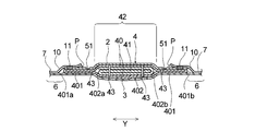
- FIG.1 (a) is a top view which shows the skin opposing surface side (surface sheet side) of the sanitary napkin which is one Embodiment of the absorbent article of this invention
- FIG.1 (b) is the sanitary napkin. It is an extraction top view which shows only this absorber.
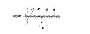
- FIG. 2 is a schematic cross-sectional view taken along the line II-II in FIG.
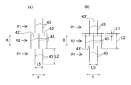
- FIG. 3A and FIG. 3B are partially enlarged plan views of the absorbent body showing a preferred arrangement of the vertical slits in the central slit region.
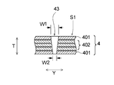
- FIG. 4 is a longitudinal sectional view of the longitudinal slit in the central slit region.
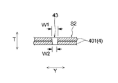
- FIG. 5 is a longitudinal sectional view of the longitudinal slit in the side slit region.
- FIG. 6 is a schematic cross-sectional view taken along line IV-IV in FIG.
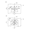
- Fig.7 (a) is a partially expanded plan view of the back slit area
- FIG.7 (b) is FIG.7 (a) equivalent view in another embodiment.
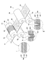
- FIG. 8 is a schematic diagram showing a process for manufacturing an absorbent body in the sanitary napkin shown in FIG. 1.
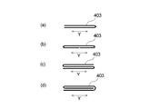
- or FIG.9 (d) are typical sectional drawings of the auxiliary
- the napkin 1 of the present embodiment includes a liquid-retaining absorbent body 4, a surface sheet 2 disposed on the skin-facing surface side of the absorbent body 4, and a non-skin of the absorbent body 4. It has an absorptive main body 5 having a back sheet 3 arranged on the opposite surface side, and has a longitudinal direction X corresponding to the wearer's front-rear direction and a transverse direction Y orthogonal thereto.
- a skin opposing surface is a surface which faces a wearer's skin side at the time of wear of an absorbent article in an absorbent article or its structural member (for example, absorbent main body 5), and is a non-skin opposing surface Is the surface of the absorbent article or its component that is directed to the side opposite to the skin side (clothing side) when the absorbent article is worn.
- the longitudinal direction X coincides with the longitudinal direction of the absorbent article (absorbent body)
- the lateral direction Y coincides with the width direction (direction orthogonal to the longitudinal direction) of the absorbent article (absorbent body).
- the absorptive main body 5 is disposed on the abdomen (front side) of the wearer relative to the excretion part facing part B disposed opposite to the wearer's liquid excretion part (such as the vaginal opening) when worn and the excretion part facing part B when worn.
- the front portion A and the rear portion C arranged on the back side (rear side) of the wearer rather than the excretory portion facing portion B at the time of wearing are provided in the vertical direction X.
- the napkin 1 further includes a pair of wing portions 7, 7 extending outward in the lateral direction Y from both side portions along the vertical direction X of the excretory portion facing portion B of the absorbent main body 5. have.
- the longitudinal direction of the absorbent article (the longitudinal direction of the absorbent article, in the figure) (X direction) is a region having a wing portion (a region sandwiched between a base on one side in the vertical direction of the wing portion and a base on the other side).
- the excretion part opposing part in the absorbent article which does not have a wing part is the transverse direction (width direction of an absorbent article, in the figure) generated when the absorbent article is folded into a tri-fold individual form.
- the two folding lines (not shown) crossing in the Y direction) are areas surrounded by the first folding curve and the second folding curve counted from the front end in the longitudinal direction of the absorbent article.
- the top sheet 2 covers the whole area of the skin-facing surface of the absorbent body 4 and further extends outward in the lateral direction Y from both side edges along the longitudinal direction X of the absorbent body 4.
- the back sheet 3 covers the entire area of the non-skin facing surface of the absorbent body 4 and further extends outward in the lateral direction Y from both side edges along the longitudinal direction X of the absorbent body 4 to be described later.
- a side flap portion 6 is formed.
- the back sheet 3 and the side sheet 10 are joined to each other by known joining means such as an adhesive, heat seal, ultrasonic seal, and the like at the extended portions from both side edges along the longitudinal direction X of the absorber 4.
- the top sheet 2 and the back sheet 3 may be bonded to the absorber 4 with an adhesive.
- the absorbent body 4 in the present embodiment has a laminated structure in which a main body absorbent sheet 401 and a central absorbent sheet 402 are laminated as shown in FIG. 2, and as shown in FIGS. 1 and 2,
- the excretory part facing part B has a multilayer part 42.
- the multilayer part 42 is a part where the number of laminated absorbent sheets 401 and 402 constituting the absorbent body 4 is larger than the part located around the multilayered part 42.
- the multilayer part 42 in this embodiment is thicker than the part located in the circumference
- the absorbent body 4 includes a main absorbent body 40 that forms the outer shape of the absorbent body 4, and an auxiliary absorbent body 41 that is smaller than the main absorbent body 40 that is arranged on a part of the main absorbent body 40. Yes.
- the auxiliary absorber 41 is located at least in the excretory part facing part B.
- the absorbent body 4 in the present embodiment is preferably composed only of a laminated structure of absorbent sheets 401 and 402, and the absorbent body 4 does not have a stacked structure of absorbent fibers such as pulp. Is preferred.
- the absorbent sheet refers to a sheet-like absorbent structure in which an absorbent material containing pulp is thinly formed using an adhesive means such as a binder.
- the main absorbent body 40 has a folded structure of a main body absorbent sheet 401 containing pulp. Specifically, the main absorbent body 40 is formed by folding the main body absorbent sheet 401 inwardly at positions of folding lines 401 a and 401 b extending along the vertical direction X. That is, the main body absorbent sheet 401 is folded at both ends. At this time, the positions of the folding lines 401a and 401b are adjusted so that the inwardly folded portions of the main body absorbent sheet 401 partially overlap each other. Therefore, the main absorbent body 40 has a laminated structure of two layers and three layers made of the main body absorbent sheet 401.
- the auxiliary absorbent body 41 has a folded structure of the central absorbent sheet 402 containing pulp. Specifically, the auxiliary absorbent body 41 folds the central absorbent sheet 402 inward along a fold line 402a extending along the longitudinal direction X at a portion located outward from the fold line 402a. Next, along the fold line 402b, the part located outward from the fold line 402b is folded inward toward the part that is folded first.
- the fold lines 402a and 402b are formed at positions that divide the length in the lateral direction Y of the central absorbent sheet 402 into approximately three equal parts. As a result, the central absorbent sheet 402 is in a folded state with three windings. Therefore, the auxiliary absorbent body 41 has a three-layer structure composed of the central absorbent sheet 402.
- the central absorbent sheet 402 that is folded in a three-fold manner is disposed inside the main body absorbent sheet 401 that is folded in both ends. That is, the main body absorbent sheet 401 and the central absorbent sheet 402 have a nested folding structure. As a result, in the laminated structure of the main body absorbent sheet 401 and the central absorbent sheet 402, it extends outward from at least a part of the peripheral edge of the central absorbent sheet 402, specifically from the entire region of the peripheral edge. A main body absorbent sheet 401 is laminated.
- assistant absorber 41 is also located in the excretion part opposing part B. .
- the main absorbent body 40 having a folded structure of the main body absorbent sheet 401 has a substantially rectangular shape with rounded corners in plan view, and extends from the front part A to the rear part C via the excretory part facing part B.
- the auxiliary absorbent body 41 having a folded structure of the central absorbent sheet 402 has a substantially rectangular shape in plan view, and is arranged from the excretory part facing part B to the rear part C in the vicinity thereof.
- the auxiliary absorbent body 41 is laminated on the skin facing surface side of the main body absorbent sheet 401 constituting the main absorbent body 40, instead of being disposed inside the main absorbent body 40 composed of the folded main body absorbent sheet 401. Alternatively, it may be laminated on the non-skin facing surface side.
- a pair of side sheets 10 and 10 are arranged over substantially the entire length in the longitudinal direction X of the absorbent main body 5 so as to overlap the left and right side portions.
- the pair of side sheets 10 and 10 are each a linear first joining line 11 located in the excretory part facing part B, and the longitudinal direction X of the first joining line 11 (front part A and rear part C). It joins to the absorptive main body 5 (surface sheet 2) with the linear 2nd joining line 12 located in this.
- the first joining line 11 has a curved shape that protrudes outward in the lateral direction Y in plan view
- the second joining line 12 has a linear shape (zigzag line shape) that extends in the longitudinal direction in plan view.
- the side sheet 10 is made of a water-repellent nonwoven fabric.
- the side flap portions 6 project greatly outward in the lateral direction Y at the excretory portion-facing portion B, whereby a pair of side flap portions 6 are provided on both the left and right sides along the longitudinal direction X of the absorbent main body 5.
- the wing portions 7, 7 are extended.
- the top sheet 2 and the back sheet 3 extend outward in the longitudinal direction X from the front end and the rear end in the longitudinal direction X of the absorbent body 4.
- the end seal portion is formed by bonding to each other by a known bonding means such as an agent, heat sealing, ultrasonic sealing or the like.
- the wing part 7 is used by being folded back to the non-skin facing surface side of the crotch part of clothes such as shorts.
- the wing portion 7 has a substantially trapezoidal shape in which a lower base (a side longer than the upper base) is positioned on the side of the absorbent main body 5 in a plan view.
- a wing part adhesive part (not shown) for fixing the wing part 7 (napkin 1) to clothing (not shown) such as shorts is formed.
- the wing portion 7 that is folded back to the non-skin facing surface (outer surface) side of the crotch portion of the clothes can be adhered and fixed to the crotch portion by the adhesive portion.
- the main body adhesion part (not shown) for fixing the absorptive main body 5 to clothes, such as shorts, is also formed in the non-skin opposing surface of the absorptive main body 5.
- the boundary line between the absorbent main body 5 and the wing portion 7 is a straight line (not shown) that connects the roots in the longitudinal direction X of the wing portion 7.
- the napkin 1 further includes a second sheet between the absorber 4 and the top sheet 2.
- the second sheet is preferably a liquid-permeable fiber sheet whose constituent fiber is a synthetic fiber.
- the synthetic fiber constituting the second sheet is preferably a weakly hydrophilic fiber from the viewpoint of mechanical compatibility while keeping the diffusibility low.
- the second sheet may be formed of fibers made of a resin such as polyester such as polyethylene, polypropylene, polyethylene terephthalate, polybutylene terephthalate, or polyamide such as nylon-6 or nylon-66, or a mixture of two or more kinds. it can.
- the mixing said here includes using 2 or more types of resin from which melting
- the thickness is preferably 0.15 mm or more, and more preferably 0.2 mm or more. Moreover, it is preferable that it is 0.4 mm or less, and it is still more preferable that it is 0.3 mm or less. The thickness is measured under a 0.5 kPa load from the viewpoint of considering the wearing state.
- an air-through nonwoven fabric in which the intersecting points of the crossed synthetic fibers are joined by air-through heat fusion can be preferably used.
- a point bond nonwoven fabric, a spunbond nonwoven fabric, a spunlace nonwoven fabric, or the like may be used.
- the basis weight is preferably 15 g / m 2 or more and 40 g / m 2 or less.
- the top sheet 2 and the second sheet are partially fixed. Thereby, the float of the surface sheet 2 is suppressed, the adhesion between the surface sheet 2 and the second sheet is improved, and the liquid is easily transferred.
- the second sheet and the absorber 4 are also partially fixed.
- Partially fixed means that there are fixed portions consisting of dots and lines, and the fixed portions are distributed over the entire sheet surface and do not need to be evenly distributed. Means no.
- the area of the fixing portion is preferably about 10% or more and 70% or less of the total area of the adherend sheet.
- the topsheet 2 and the second sheet are partially fixed by applying an adhesive intermittently or intermittently heat-sealing.
- the adhesive When the adhesive is applied intermittently, the adhesive is applied intermittently using a known means such as a slot coat gun, spirally applied using a spiral spray gun, or spray gun.
- the surface sheet 2 is applied in the form of a mist intermittently using a dot gun or in the form of dots using a dot gun to maintain the fluid permeability between the surface sheet 2 and the second sheet. And the second sheet are partially bonded.
- a hot melt adhesive is preferably used as the adhesive to be applied.
- hot melt adhesive examples include styrene and olefin.
- Styrene-based hot melt adhesives include styrene-butadiene-styrene copolymer (SBS), styrene-isoprene-styrene copolymer (SIS), and styrene-ethylene-butylene-styrene copolymer that is a hydrogenated product of SBS. (SEBS) and blended hot melt adhesives in which two or more of these are blended can be used.
- SBS styrene-butadiene-styrene copolymer
- SIS styrene-isoprene-styrene copolymer
- SEBS blended hot melt adhesives in which two or more of these are blended can be used.
- a blended hot melt adhesive of SIS and SBS or a blended hot melt adhesive of SIS and SEBS is particularly preferably used in the present invention.
- the application amount of the hot melt adhesive is preferably 3 g / m 2 or more and 10 g / m 2 or less.
- a laminated sheet of the top sheet 2 and the second sheet is made up of a hot embossing roll and a flat roll.
- the top sheet 2 and the second sheet are partially fused by being conveyed in between and embossed.
- the interval between the plurality of fusion points formed by fusing is 5 mm or more and 15 mm from the viewpoint of maintaining appropriate fluid adhesion between the top sheet 2 and the second sheet and maintaining the fluid permeability. The following is preferable.
- the surface sheet 2 and the absorber 4 are dented integrally on the skin opposing surface (skin opposing surface of the surface sheet 2) of the absorptive main body 5 toward the back surface sheet 3 side.
- the linear groove is formed so as to extend in the horizontal direction Y in the vertical groove 51 extending in the vertical direction X in the excretory part facing part B and in the front part A and the rear part C, respectively.
- the first and second lateral grooves 52 and 53 are formed.
- channel can be formed in accordance with a conventional method by pressing process with or without heat, or embossing, such as ultrasonic embossing.
- the surface sheet 2 and the absorber 4 are not shown in the figure, but are bonded by an adhesive or integrated by thermal fusion or the like.
- linear groove can prevent liquid leakage from the periphery of the napkin 1 by suppressing the diffusion of the liquid in the planar direction of the absorber 4. What is necessary is just to set the width
- “linear” in the linear groove is not limited to a straight line in the plan view, but includes a curved line, and each line may be a continuous line or a broken line.
- the linear groove may be composed of a row formed by a large number of discontinuous point embosses.
- the napkin 1 of this embodiment is formed left-right symmetrically with respect to the centerline (not shown) which bisects the absorptive main body 5 to the horizontal direction Y, as shown in FIG.
- the napkin 1 of the present embodiment has an excretory part in which the absorber 4 is formed in a state in which a plurality of vertical slits 43 along the vertical direction X are dispersed in the excretory part facing part B.
- a slit region S is provided.
- region S is comprised from the center slit area
- the central slit region S1 is located at the central portion in the lateral direction Y of the absorbent body 4 in the excretory portion facing portion B.
- the central slit region S1 substantially coincides with the multilayer portion 42, that is, the portion where the main body absorbent sheet 401 and the central absorbent sheet 402 are laminated.
- the side slit region S2 is located outside the central slit region S1 in the lateral direction Y.
- the side slit region S2 substantially coincides with a portion where the absorbent body 4 is formed only by the main body absorbent sheet 401.
- the vertical slits 43 in the excretion part slit region S are formed in a state dispersed in both the vertical direction X and the horizontal direction Y. As shown in FIG. 2, the vertical slit 43 is formed by cutting the absorber 4 in the thickness direction, and penetrates the laminated structure of the absorbent sheets 401 and 402 constituting the absorber 4. It is preferable.
- the vertical slits 43 are not formed on the top sheet 2 and the back sheet 3 disposed above and below the absorbent body 4 and are made of a nonwoven fabric that may be disposed between the top sheet 2 and the absorbent body 4. It is preferable that the intermediate sheet is not formed.
- Each vertical slit 43 is individually independent, and a non-slit portion 43 ′ is located between adjacent vertical slits 43.
- Each vertical slit 43 is surrounded by a non-slit portion 43 ′ around the entire periphery.
- the vertical slit 43 is formed by cutting the absorber 4 in the thickness direction, and is formed from a cut having substantially no width, or preferably 1.5 mm. It has the following narrow space.
- the width means the length of the vertical slit 43 in a direction orthogonal to the direction in which the vertical slit 43 extends.
- the absorber 4 has slit rows R ⁇ b> 1 and R ⁇ b> 2 including a plurality of vertical slits 43 spaced in the horizontal direction Y in the vertical direction X of the napkin 1. Multiple rows are formed.
- a slit row R1 composed of two vertical slits 43 spaced in the horizontal direction Y and a slit row R2 composed of three vertical slits 43 spaced in the horizontal direction Y are shown.
- a slit row composed of at least two vertical slits 43 spaced apart in the horizontal direction Y is arranged in the vertical direction X. It is sufficient that two rows are formed.
- the slit rows are preferably formed in 3 or more rows in the vertical direction X, more preferably 4 rows or more, and even more preferably 5 rows or more. Further, the number of vertical slits separated in the horizontal direction X included in each slit row is preferably 2 or more, more preferably 3 or more, and further preferably 4 or more.
- the overlapping length L1 is the length of the vertical slits constituting the slit row. It is preferably 20% or less of the length L2 in the same direction X, and preferably 10% or less.
- the positions of the slits in the slit rows adjacent in the longitudinal direction X of the napkin 1 are shifted in the lateral direction Y of the napkin 1.
- the vertical slits 43 in the two slit rows R1 and R2 adjacent to each other in the vertical direction X are such that the slit 43 of one slit row R1 is located at the center between the slits 43 of the other slit row R2.
- the slit 43 of one slit row R1 may be formed so as to be biased to one side between the slits 43 of the other slit row R2.
- FIG. 4 shows a longitudinal sectional view of the absorbent body in the longitudinal slit 43 formed in the central slit region S1 and in the vicinity thereof.
- FIG. 5 is a longitudinal sectional view of the absorbent body in the longitudinal slit 43 formed in the side slit region S2 and a portion in the vicinity thereof.
- a five-layer structure composed of a three-layer structure portion in which the central absorbent sheet 402 is folded and main body absorbent sheets 401 and 401 positioned above and below the three-layer structure portion.
- a vertical slit 43 is formed in the laminated structure. The vertical slit 43 penetrates the laminated structure of the five-layer structure over the entire thickness direction.
- the vertical slit 43 is formed in a two-layer laminated structure in which the main body absorbent sheet 401 is folded.
- the vertical slit 43 penetrates the laminated structure of the two-layer structure over the entire region in the thickness direction.
- FIG. 4 shows a state where all the absorbent sheets adjacent in the thickness direction are not joined. In the figure, a gap is provided between the absorbent sheets for the purpose of visually expressing that the absorbent sheets are in a non-bonded state (the same applies to FIG. 5).
- the gap may be formed or may not be formed. From the viewpoint of increasing the liquid holding capacity when repeatedly absorbing the liquid and preventing a decrease in the absorption rate, it is preferable that a gap is formed between the absorbent sheets. Moreover, in FIG. 4, between all the absorptive sheets adjacent in the thickness direction is in a non-joined state, but the absorptive sheets are in a non-joined state in at least one location of the adjacent absorbent sheets It only has to be.
- the absorbent sheet has a macroscopically flat shape, but microscopically, the surface of the absorbent sheet has a fine concavo-convex shape, so only the operation of overlapping the absorbent sheets is performed. Thus, a gap is generated between the absorbent sheets. This void is maintained unless the laminated structure of the absorbent sheet is intentionally compressed.
- the absorbent sheet adjacent in the thickness direction is in a non-bonded state at the site where the vertical slit 43 is formed, so that the liquid excreted in the napkin 1 reaches the absorber 4 through the top sheet 2 and the vertical slit When flowing into 43, the liquid smoothly diffuses in the plane direction of the absorber 4 through the inner surface of the vertical slit 43.
- the liquid is likely to be drawn by capillary action, so that the liquid is more easily diffused in the plane direction. As a result, the liquid absorption rate is increased.
- the length of the vertical slit 43 in the horizontal direction Y is viewed along the thickness direction T of the absorbent body 4, the length W1 on the top sheet side is closer to the back sheet side. Is longer than the length W2. 4 and 5 show a state in which the length in the horizontal direction Y of the vertical slit 43 is gradually reduced from the top sheet side to the back sheet side.
- the length of the vertical slit 43 in the horizontal direction Y does not need to be changed in this way, and may be decreased stepwise from the top sheet side to the back sheet side, for example.
- the length W1 of the vertical slit 43 on the top sheet side is longer than the length W2 on the back sheet side, so that the liquid can be easily received in the vertical slit 43, which also increases the liquid absorption rate. Get faster.
- the vertical slit 43 has such a structure, the external force applied to the napkin 1 is not easily transmitted to the back sheet side of the absorbent body 4 when the napkin 1 is attached, and the napkin 1 is attached to the underwear. Can be fixed stably.
- the fact that the external force is less likely to be transmitted to the back sheet side of the absorber 4 also leads to the maintenance of the flat shape of the absorber 4 on the back sheet side, which also stably fixes the napkin 1 to the undergarment. become able to. As a result, even if an external force is applied to the napkin 1, the napkin 1 is not easily displaced from the proper mounting position, and as a result, a decrease in absorbability and a decrease in mounting feeling are effectively prevented.
- the cross-sectional shape of the vertical slit 43 along the thickness direction T of the absorber 4 can be observed at a magnification of 20 to 100 times using a microscope (for example, VHX-1000 manufactured by KEYENCE).
- the cross section along the thickness direction T of the absorber 4 can be formed, for example, by cutting the absorber 4 with a blade razor manufactured by Feather Corporation.
- W1 / W2 which is the ratio of W1 to W2 described above, is preferably 5 or more, and more preferably 10 or more. Further, W1 / W2 is preferably 80 or less, and more preferably 60 or less. For example, W1 / W2 is preferably 5 or more and 80 or less, and more preferably 10 or more and 60 or less.
- the density of the absorbent sheet in the vicinity of the vertical slit is larger than the density of the absorbent sheet in the non-slit portion 43 ′ described above.
- the density of the absorbent sheet in the vicinity of the longitudinal slit 43 is preferably 1.05 times or more the density of the absorbent sheet in the non-slit portion 43, 1.2 More preferably, it is twice or more. Further, it is preferably 2 times or less, and more preferably 1.8 times or less.
- the density of the absorbent sheet in the vicinity of the longitudinal slit 43 is preferably 1.05 to 2 times the density of the absorbent sheet in the non-slit portion 43, and is 1.2 to 1.8 times. More preferably.
- the density can be measured as follows.
- the density of the absorbent sheet in the vicinity of the longitudinal slit and in the non-slit portion 43 ′ was determined by testing the absorbent sheet in the vicinity of the longitudinal slit and the absorbent sheet in the non-slit portion 43 ′ with a width of 3 mm and a length of 20 mm, respectively. Cut into pieces and measure the thickness of the test piece in the center in the width direction using a non-contact type laser displacement meter (manufactured by KEYENCE, displacement gauge LK-GD500 and laser head LK-G30). Measurement was performed using a balance (Electronic balance GR-300 manufactured by A & D, accuracy: 4 digits after the decimal point), the volume was calculated from the measured thickness, and the mass was divided by the volume.
- the absorbent body 4 extends at a rear part C located behind the excretory part facing part B so as to have a longitudinal direction in a direction intersecting the longitudinal direction X of the napkin 1.
- a plurality of rear slits 45 are provided.
- the rear slit 45 has a position of the central portion 45a in the longitudinal direction of the slit 45 from the positions of both end portions 45b and 45b in the longitudinal direction.
- the back slit 45 is formed in multiple numbers at intervals in the longitudinal direction X of the absorbent article.
- the length L3 in the lateral direction Y of the rear slit region S3 formed by the rear slit 45 is shorter than the length L4 in the same direction Y of the excretory slit region S.
- the excretory part slit region S is shown as a range slightly wider than the range in which the vertical slits 43 are distributed from the viewpoint of easiness to see in both the vertical direction X and the horizontal direction Y. is there.
- the excretion portion slit region S in the present invention is a range in which the vertical slits 43 are distributed
- the length L4 in the horizontal direction Y is the vertical length located at both ends in the horizontal direction Y as shown in FIG. This is the distance between the outer edges of the slits 44.
- the rear slit region S3 formed by the rear slit 45 is a rectangle having two sides along the vertical direction X and two sides along the horizontal direction Y. This is the area inside the smallest rectangle that encloses all).
- the rear slit region S3 is also shown in FIG. 1 (b) as a slightly wide range for convenience from the viewpoint of ease of viewing.
- FIG. 7B when a plurality of the rear slits 45 are formed in the vertical direction X with the horizontal direction Y shifted, the length L3 in the horizontal direction Y of the rear slit region S3 is the outermost side. The distance between the ends located at.
- the center position 4 c that bisects the lateral length of the absorber 4 and the center position that bisects the longitudinal length of the rear slit 45. 45c is arranged so as to substantially match.
- substantially coincide means that the center position 4c of the absorber 4 and the center position 45c of the rear slit may be shifted by a length of 10% of the lateral length of the absorber 4.
- the lengths in the longitudinal direction of the plurality of rear slits 45 are substantially the same.
- “substantially the same” means that the difference in length is within 5% of the length L3 in the lateral direction Y of the rear slit region S3.
- the center positions 45c of the plurality of rear slits 45, 45 substantially coincide with each other.
- “substantially match” means that the absorber 4 may be displaced by a length of 5% of the lateral length.
- the rear slit 45 is formed between the two layers of the main body absorbent sheet 401 forming the laminated structure, similarly to the longitudinal slit 43 formed in the excretory portion slit region S described above. It is preferable that it is in a non-joined state at the site. As a result, not only the excretory part facing part B but also the rear part C, the liquid absorption speed is increased. From the viewpoint of further increasing the absorption speed of the liquid, the rear slit 45 has the length on the surface sheet side when the length in the longitudinal direction X of the rear slit 45 is viewed along the thickness direction of the absorber 4. It is preferable that the length is longer than the length on the back sheet side.
- the density of the main body absorbent sheet 401 in the vicinity of the rear slit 45 is higher than the density of the main body absorbent sheet 401 in the non-slit portion located between the rear slits 45.
- the length in the longitudinal direction X of the rear slit 45 and the density in the vicinity of the rear slit 45 can be measured by the same method as in the case of the vertical slit 43 described above.
- the absorbent body 4 is moved in the lateral direction X by the wearer's thigh when the napkin 1 is worn. Even if a compressive force is applied, the absorbent body 4 is finely deformed at various parts of the excretory part slit region, and therefore, there is an advantageous effect that deep folds are hardly generated in the absorbent body 4 and the napkin 1. Played. Therefore, it is possible to prevent the wearer from feeling uncomfortable due to the deep crease, or the liquid flowing along the crease and leading to leakage.
- the napkin 1 has no gap between the adjacent slit rows R1 and R2, so that the napkin caused by the pressure from the thigh is compared with the case where there is a gap between the slit rows R1 and R2. 1 is unlikely to occur.
- the slit rows R1 and R2 are deformed along the shape of the movement and body and difficult to fold deeply. The creases generated at the part are easily transmitted to the non-slit portions in the slit row and become liable to be kinked.
- a difference in rigidity is generated between the portion having the slit row and the portion at the interval between the slit rows, and the folding at the boundary is likely to occur, and the fit to the body is likely to be lowered.
- the napkin 1 has a plurality of rear slits 45 in the rear portion C that extend in the direction intersecting the longitudinal direction X of the absorbent article and are curved in a convex shape toward the front portion A. Since it is formed, even in a part that has to be curved in the front-rear direction according to the shape of the body while receiving the force from the thigh from the vicinity of the rear end part of the excretion part facing part B to the rear part C, The absorber 4 and the napkin 1 are easily deformed along the wearer's movement and body shape. Therefore, in spite of using the absorber 4 which consists of a laminated body of an absorbent sheet, the outstanding fitting property, leak prevention property, and a feeling of wear are obtained.
- the excretion area is the area that receives the highest pressure from the thigh, and it is preferable that a slit is formed over the full body of the absorber as much as possible to fit the complex shape and movement of the body, It is important to fit the body so that it receives little pressure from the thigh, but rather is along the longitudinal direction of the body.
- the transversal movement of the napkin 1 caused by the pressure of the thigh and the transmission to the rear part C of the heel is prevented by forming a slit in the direction intersecting the excretion part facing part B, and excretion.
- the width equal to or smaller than the width of the slit region of the part facing part B
- the rear part C does not become too flexible and can be deformed so as to wrap the heel part along the body.
- the length L3 of the rear slit region S3 and the length L4 of the excretory part slit region S to be the same length, the napkin 1 generated at the excretory part facing part B is stretched along the front-rear direction. The effect of preventing transmission to the rear part C can be further enhanced.
- each rear slit 45 may be gradually shortened toward the rear of the napkin 1, and only the rearmost rear slit 45 is more than the front rear slit 45. It may be shorter.
- the lengths of the plurality of rear slits 45 are different and the center positions in the longitudinal direction are aligned, the length L3 of the rear slit region S3 and the longest rear The linear distance between both ends in the longitudinal direction of the slit 45 coincides.
- the length of the rear slit 45 is gradually shortened toward the rear, it is possible to effectively prevent biting into the fissure while following the front and rear body curved shapes to some extent.
- the length of the rearward rear slit 45 is designed to be short, it may be caused by a difference in rigidity between the slit region and the non-slit region at a portion having no slit behind the rear slit 45. , Can prevent a sense of discomfort caused by folding. In particular, it is more effective when the rearmost slit and the end of the absorber 4 are relatively close to each other. More preferably, the length L3 of the rear slit region 45 is not less than 50% and not more than 100% of the length 4 of the excretory part slit region S.
- the manufacturing process of a napkin has the process of forming the back slit extended in the direction orthogonal to this conveyance direction, conveying an absorber or its continuous body in those longitudinal directions, the absorber after slit formation Etc., the absorber and the like are easily broken.
- the rear slit 45 is shaped so that the central portion 45a in the longitudinal direction of the slit is positioned on the front side with respect to the positions of both end portions 45b and 45b in the longitudinal direction.
- the rear slit 45 is a plan view curved convexly toward the front side, for example, an arc shape or a parabolic shape, from the viewpoint of preventing tearing during conveyance of the absorbent body, forming gaps described later, and workability. It is preferable that it is U-shaped.
- the absorber 4 preferably has one or more of the following configurations.
- the length L2 (see FIG. 3) along the vertical direction X of the vertical slit 43 in the excretory part slit region S is preferably 10 mm or more, more preferably 15 mm or more, and preferably 35 mm or less, more preferably 30 mm or less. Moreover, it is preferably 10 mm or more and 35 mm or less, more preferably 15 mm or more and 30 mm or less.
- the interval L5 (see FIG. 3) of the vertical slits 43 in the same slit row in the excretory part slit region S is preferably 3 mm or more, more preferably 7 mm or more, preferably 20 mm or less, more preferably 15 mm or less, Moreover, Preferably they are 3 mm or more and 20 mm or less, More preferably, they are 7 mm or more and 15 mm or less.
- the longitudinal slit 43 preferably has a range of 5 mm or more, more preferably 7.5 mm or more from the end of the absorber 4 inward. It is preferable that it is a non-slit part which is not formed. Moreover, it is preferable that the range of 15 mm or less, more preferably 12.5 mm or less is a non-slit part. For example, it is preferable that a range of 5 mm or more and 15 mm or less, particularly a range of 7.5 mm or more and 12.5 mm or less is a non-slit portion in which the vertical slit 43 is not formed.
- the edge part of the absorber 4 said here is a side edge along the vertical direction X of this absorber 4. As shown in FIG.
- the length L4 in the lateral direction Y of the excretory part slit region S is preferably 30% or more, more preferably 40% or more, and preferably 40% or more of the length in the same direction Y of the absorbent body 4 in the excretion part facing part B. Is 85% or less, more preferably 75% or less.
- the length L4 in the lateral direction Y of the excretory part slit region S is preferably 30 mm or more, more preferably 40 mm or more, and preferably 55 mm or less, more preferably 45 mm or less.
- the length L3 in the lateral direction Y of the rear slit region S3 formed by the rear slit 45 is preferably 30% or more of the length in the same direction Y of the absorber 4 in the portion having the rear slit 45, and Preferably it is 40% or more, Preferably it is 65% or less, More preferably, it is 55% or less. Further, the ratio of the length L3 in the lateral direction Y of the rear slit region S3 formed by the rear slit 45 to the length L4 in the lateral direction Y of the excretory slit region S is preferably 1 or less, more preferably 5 /. It is 6 or less, preferably 2/5 or more, more preferably 1/2 or more.
- the length L3 in the lateral direction Y of the rear slit region formed by the rear slit 45 is preferably 20 mm or more, more preferably 25 mm or more, and preferably 50 mm or less, more preferably 45 mm or less.
- the length L6 in the vertical direction X is preferably 5% or more, more preferably 7.5% or more of the length L3 in the horizontal direction Y. Further, it is preferably 17.5% or less, more preferably 15% or less.
- the absorbent body 4 of the napkin 1 includes a multi-layer part in which the number of laminated absorbent sheets is larger than the part located in the excretory part facing part B as shown in FIG. 1 (a) and FIG. 42, and the central slit region S1 is formed in the multilayer portion 42.
- the rear slit 45 is formed in a portion located behind the multilayer portion 42 and having a smaller number of laminated absorbent sheets than the multilayer portion 42. Therefore, since the pressure from the thigh and the complex shape and movement of the body are added to the central slit region S1 formed in the excretory part facing part B, the rigidity can be increased and the kinking can be prevented by forming a multilayer structure. Since the rear slit region is formed at a portion corresponding to the buttocks, the complex deformation does not occur as in the central region. In addition, it is possible to prevent a feeling of strangeness particularly when sitting.
- the manufacturing process of the napkin 1 has the process of forming the back slit extended in the direction orthogonal to this conveyance direction, conveying an absorber or its continuous body in those longitudinal directions, absorption after slit formation is carried out.
- a gap 46 in which the slit is opened at the central portion 45a in the longitudinal direction of the rear slit 45 as shown in FIG. Can be formed.
- the central portion 45a is located on the front side from the positions of the both end portions 45b and 45b, and the central portion 45a has a gap 46 with the slit open, so that the body shape is obtained.
- the deformability to the shape along is further improved.
- the rear slit 45 is in the vicinity of both end portions 45b in the longitudinal direction, and the non-opening region of the slit. It is preferable to have.
- the absorber etc. after the slit formation is pulled in the transport direction, so that the absorber etc. is appropriately necked.
- the rear slit 45 having a non-opening region of the slit can be easily formed at both end portions 45b and 45b while having a gap at the central portion 45a.
- the rear slit 45 having the gap 46 in the central portion 45a has a width L7 ( 7 (a)) is preferably 0.05% or more, more preferably 0.075% or more with respect to the length L3 in the lateral direction Y of the rear slit region S3 formed by the rear slit 45. Yes, preferably 10% or less, more preferably 8% or less. Further, from the same viewpoint, the width L7 (see FIG. 7A) of the slit 45 in the central portion 45a is preferably 0.3% or more with respect to the length L6 in the longitudinal direction X of the rear slit 45.
- the gap 46 in the central portion 45a of the rear slit 45 is preferably a width that disappears when the absorbent body 4 is bent along the body shape during use of the napkin 1, from the viewpoint of preventing absorption inhibition.
- the rear slit 45 of the absorber 4 in the present embodiment has a rear end position P1 of the rear slit located in front of the rear slits adjacent to each other in the vertical direction X of the napkin. It is formed so as to be positioned in front of the front end position P2 of the rear slit positioned rearward.
- the absorber when slitting the absorber at the time of product processing, it is possible to prevent the pressure of the slit blade in the width direction of the absorber from being dispersed, and to cleanly slit from the top to both ends. Further, when the rear slit is mounted along the buttocks, the top of the opening is closed or slightly bent so as to be overlapped, which is also advantageous in terms of ease of deformation for conforming to the body shape. From this point of view, the distance L8 [FIG.
- the absorber 4 in this embodiment has the cyclic
- FIG. 8 schematically shows a manufacturing process of the absorber 4 in the present embodiment.
- a cutter roll 61 having a plurality of cutting blades 63 formed in a circumferential surface dispersed in the circumferential direction and the axial length direction of the roll, and an anvil roll that receives the cutting blades 63 of the cutter roll 61.
- the cutting device 60 provided with 62 is used.
- a nip device 66 having a pair of nip rolls 64 and 65 having a smooth peripheral surface is used.
- the cutter roll 61 and the anvil roll 62 are arranged so that their axes are parallel.
- a clearance is provided between the cutter roll 61 and the anvil roll 62, or both rolls are in contact with each other.
- the cutting blade 63 positioned on the peripheral surface of the cutter roll 61 is formed and arranged so as to coincide with the shapes of the slits 43 and 45 formed in the target absorbent body 4. In FIG. 8, only the cutting blade 63 for forming the vertical slit 43 is shown.
- the nip device 66 the pair of nip rolls 64, 65 are arranged so that their axes are parallel.
- a clearance is provided between the pair of nip rolls 64 and 65, or both rolls are in contact with each other.
- the axes of the rolls 61 and 62 of the cutting device 60 and the axes of the rolls 64 and 65 of the nip device 66 are parallel to each other.
- the raw fabric 4a of the absorbent body 4 composed of a laminated structure of the main body absorbent sheet and the central absorbent sheet is conveyed in the direction indicated by the arrow R in FIG. 8 and the cutter roll 61 and the anvil roll 62 in the cutting device 60 are conveyed. Supplied between.
- the state of the cross section in the thickness direction of the original fabric 4a before being supplied between the two rolls 61 and 62 is shown in a circle indicated by I in FIG. In the raw fabric 4a before being supplied between the two rolls 61 and 62, the absorbent sheets 401 and 402 are not joined.
- the cutting blade 63 enters the raw fabric 4a, so that the absorbent sheets 401 and 402 are disposed on one side in the vicinity of the vertical slit 43 formed. Projecting toward the other surface.
- One surface is a surface in contact with the cutter roll 61, and the other surface is a surface in contact with the anvil roll 62.
- the protruding absorbent sheets 401 and 402 are consolidated due to the progress of the cutting blade 63 and are in a joined state. It has become.
- This consolidation increases the density of the absorbent sheets 401 and 402 in the vicinity of the vertical slit 43. In the part away from the vertical slit 43, the compaction of the absorbent sheets 401, 402 does not occur or the degree thereof is low, so that the densification has not occurred or the degree of densification has become low. Yes.
- the original fabric 4a in which the slit is formed in this way is continuously supplied between the pair of nip rolls 64 and 65 in the nip device 66.
- the state of the cross section in the thickness direction of the raw fabric 4a after being nipped by both the rolls 64, 65 is shown in a circle indicated by III in FIG. Due to the nip between the two rolls 64 and 65, the protruding portions of the absorbent sheets 401 and 402 that have occurred in the vicinity of the vertical slit 43 are pushed back into the vertical slit 43, and the absorbent sheets 401 and 402 are flattened.
- each absorbent sheet 401,402 joined until then separates, and a space
- the absorbent sheet positioned closer to the cutter roll 61 has a greater degree of cutting by the cutting blade 63.
- the extent of cutting becomes smaller as the absorbent sheet is located farther from the cutter roll 61.
- the width of the slit becomes wider as the absorbent sheet is located closer to the cutter roll 61, and conversely, the position is located farther from the cutter roll 61.
- the width of the slit becomes narrower as the absorbent sheet is made. The difference between the widths of the slits becomes more prominent as the thickness of the original fabric 4a increases or the number of laminated absorbent sheets 401 and 402 increases.
- slits vertical slits 43 and rear slits 45 having a desired shape can be successfully formed.
- the surface sheet 2 and the back surface sheet 3 various things conventionally used in the said technical field can be especially used without a restriction
- the surface sheet 2 for example, liquid permeable sheets such as various nonwoven fabrics and perforated films subjected to a hydrophilic treatment can be used.
- a liquid-impermeable material or a water-repellent material can be used.
- the liquid-impermeable material a resin film, a resin film having fine pores and moisture permeability, a laminate material of a resin film and a nonwoven fabric, and the like can be used.
- the absorbent sheets 401 and 402 constituting the absorbent body 4 between the constituent fibers such as pulp or the configuration through the adhesive force generated in the wet water-absorbing polymer or a binder such as an adhesive or adhesive fiber added separately.
- a sheet formed by bonding between the fiber and the water-absorbing polymer can be preferably used.
- an absorbent sheet containing pulp produced by the method described in JP-A-8-246395, pulverized pulp supplied on an air stream, and a water-absorbing polymer are deposited, and then an adhesive is deposited.
- An absorbent sheet obtained by blending a superabsorbent polymer during the production process of a spunbond or meltblown nonwoven fabric can be used.
- These absorptive sheets can be used as a sheet-like absorber by cutting one sheet into a predetermined shape.
- the thickness per absorbent sheet is preferably 0.1 mm or more, particularly 0.3 mm or more, and preferably 2 mm or less, particularly 1.5 mm or less. More specifically, it is preferably 0.1 mm or more and 2 mm or less, particularly preferably 0.3 mm or more and 1.5 mm or less.
- the main body absorbent sheet 401 and the central absorbent sheet 402 constituting the absorbent body 4 are each folded to form a laminated structure composed of a plurality of layers.
- a laminate of a plurality of adhesive sheets may be used.
- the absorbent sheet can be folded in various ways.
- the auxiliary absorbent body 41 in the present embodiment has the central absorbent sheet 402 as shown in FIGS. 9 (a) to 9 (d). It may be folded in a simple way.
- the absorber 4 has a thickness in the multilayer portion 42 of preferably 0.7 mm or more, more preferably 1 mm or more, preferably 5 mm or less, more preferably 4 mm or less, more specifically preferably It is 0.7 mm or more and 5 mm or less, More preferably, it is 1 mm or more and 4 mm or less.
- the absorber 4 has a thickness in a portion other than the multilayer portion 42 of preferably 0.3 mm or more, more preferably 0.5 mm or more, and preferably 3 mm or less, more preferably 2.5 mm or less. More specifically, it is preferably 0.3 mm or more and 3 mm or less, more preferably 0.5 mm or more and 2.5 mm or less. This range is preferable from the viewpoint of enhancing the high absorption performance and the ability to follow the wearer's movement.
- the thickness difference (step) between the multilayer part 42 and the peripheral part thereof or at the vicinity thereof is preferably 2 mm or less, and more preferably 1.5 mm or less.
- the purpose is to suppress the occurrence of kinking in the vicinity of the boundary between the multilayer portion 42 and the area where only the main absorbent body 40 in the peripheral portion exists in the excretory portion facing portion B. If this step is large, the napkin 1 tends to fill the gap due to the step when the napkin 1 follows the movement of the wearer during wearing. By setting within the range, the effect of suppressing the occurrence of kinks in the excretory part facing part B is enhanced.
- the thickness of each part of the absorber 4 described above is measured by the following method.
- ⁇ Measurement method of absorber thickness The absorber, which is the measurement object, is placed in a horizontal place so that there is no wrinkle or bending, and the thickness under a load of 5 cN / cm 2 is measured.
- a thickness meter PEACOCK DIAL UPRIGHT GAUGES R5-C (manufactured by OZAKI MFG.CO.LTD.) was used for measuring the thickness in the present invention.
- a circular plate or a square plate (acrylic plate having a thickness of about 5 mm) in a plan view is disposed between the tip of the thickness meter and the measurement portion of the measurement object, and the load is 5 cN / cm 2 . Adjust the size of the plate so that
- Examples of the water-absorbing polymer contained in the absorbent sheets 401 and 402 include sodium polyacrylate, (acrylic acid-vinyl alcohol) copolymer, crosslinked sodium polyacrylate, and (starch-acrylic acid) graft copolymer. (Isobutylene-maleic anhydride) copolymer and saponified product thereof, polyaspartic acid, and the like.
- the absorbent sheets 401 and 402 constituting the absorbent body 4 are preferably both water-absorbing sheets containing a water-absorbing polymer, but the water-absorbing sheet containing the water-absorbing polymer and the water-absorbing polymer are also preferred. It is good also as a laminated body of the water-absorbing sheet which comprises an absorber, combining the water-absorbing sheet which does not contain.
- a liquid-impermeable or water-repellent resin film a laminate of a resin film and a nonwoven fabric, or the like can be used.
- Other materials include, for example, spunbond nonwoven fabrics, composite sheets of spunbond nonwoven fabric (S) and meltblown nonwoven fabric (M) (SM, SMS, SMMS, etc.), heat roll nonwoven fabrics, air-through nonwoven fabrics, etc.
- An aqueous (hydrophobic) non-woven fabric may be mentioned.
- the napkin 1 may not have the wing part 7.
- region S may be formed only in the excretion part opposing part B, may be extended to a part of back part C from the excretion part opposing part B, and an excretion part opposing part From B, a part of the front part A and a part of the rear part C may be extended.
- the number of laminated absorbent sheets in the multilayer portion 42 is not limited to the number shown in FIG.
- the difference in the number of laminated absorbent sheets between the multilayer portion 42 and other portions is not limited to the number shown in FIG.
- the number of the rear slits 45 may be two, three, five or more, and the rear slit having a gap 46 in which the slit is opened in the central portion 45a and the rear without such a gap.
- a slit may be mixed.
- the rear slit 45 may have a shape in which two straight lines are joined at an angle at the center of the slit.
- the slit that penetrates the absorber 4 is preferable as described above.
- the slit may be non-penetrating or may be partially non-penetrating. Examples of the non-penetrating slit include those in which the skin facing surface side or the non-skin facing surface of the absorbent body 4 is not open.
- the slit rows R1 and R2 may be provided between R2.
- the absorbent article of the present invention may be a sanitary napkin, a panty liner (cage sheet), an incontinence pad, or the like.
- a liquid-retaining absorbent body a top sheet disposed on the skin facing surface side of the absorbent body, and a back sheet disposed on the non-skin facing surface side of the absorbent body, and excreted by the wearer when worn
- An excretory part facing part disposed opposite to the part, a front part disposed on the abdomen side of the wearer from the excretion part facing part, and a rear part disposed on the back side of the wearer from the excretion part facing part.
- An absorbent article having a longitudinal direction corresponding to the wearer's front-rear direction and a lateral direction perpendicular to the wearer's front-rear direction, wherein the absorbent body is laminated with a plurality of absorbent sheets containing pulp. And the laminated structure of the absorbent sheet extends outwardly from at least a part of the central absorbent sheet located at the excretory part facing portion and the peripheral edge of the central absorbent sheet.
- the central absorbent sheet and the laminated main body absorbent sheet And has a plurality of longitudinal slits cut in the thickness direction of the absorbent body along the longitudinal direction in the excretory part facing portion in the absorbent body, and is formed in a dispersed state.
- a part between the absorbent sheets of a plurality of layers forming the laminated structure is in a non-bonded state at a site where the vertical slit is formed. Sex goods.
- the length W1 on the top sheet side is the length W2 on the back sheet side.
- the absorbent article according to ⁇ 1> wherein the absorbent article is longer.
- a ratio W1 / W2 of the length W1 on the top sheet side and the length W2 on the back sheet side is 5 times or more and 80 times or less.
- ⁇ 4> The above ⁇ 1> to ⁇ 3>, wherein the density of the absorbent sheet in the vicinity of the vertical slit is higher than the density of the absorbent sheet in a non-slit portion positioned between the vertical slits.
- ⁇ 5> The absorbent article according to ⁇ 4>, wherein the density of the absorbent sheet in the vicinity of the longitudinal slit is 1.05 to 2 times the density of the absorbent sheet in the non-slit portion.
- ⁇ 6> A plurality of slit rows composed of a plurality of the vertical slits spaced apart in the horizontal direction are formed in the vertical direction, and there is no interval between adjacent slit rows in the vertical direction, and in the vertical direction.
- the vertical slit has a length along the vertical direction of 10 mm or more and 35 mm or less, and an interval between the vertical slits in a slit row composed of a plurality of the vertical slits spaced apart in the horizontal direction is 3 mm or more and 20 mm or less.
- the absorbent article according to any one of ⁇ 1> to ⁇ 6>, wherein a range of 5 mm to 15 mm is a non-slit portion inward from the end of the absorber.
- the absorber has a rear slit extending in a direction intersecting the longitudinal direction at the rear portion, and the rear slit has a center portion in the longitudinal direction of the slit at both end portions in the longitudinal direction.
- the rear slit has a plan view shape that is convexly curved toward the front portion.
- positioned is comprised from the center slit area
- ⁇ 14> The absorption according to ⁇ 12> or ⁇ 13>, wherein the absorption sheet between the absorbent sheets forming the laminated structure is also in a non-bonded state in the portion where the vertical slit is formed in the side slit region. Sex goods.
- ⁇ 15> The absorbent article according to any one of ⁇ 1> to ⁇ 14>, wherein the central absorbent sheet is disposed inside a main body absorbent sheet that is folded at both ends.
- ⁇ 16> The absorbent article according to any one of ⁇ 1> to ⁇ 15>, wherein the vertical slit is not formed in a top sheet and a back sheet disposed above and below the absorber.
- the absorbent sheet is a sheet formed by bonding between constituent fibers or between constituent fibers and the water-absorbing polymer through adhesive strength of the water-absorbing polymer or a binder added separately.
- ⁇ 18> The absorbent article according to any one of ⁇ 1> to ⁇ 17>, wherein the main body absorbent sheet and the central absorbent sheet are each folded to form a laminated structure including a plurality of layers.
- the portion where the central absorbent sheet is disposed is a multilayer portion having a thickness greater than that of the surrounding portion, and the thickness of the multilayer portion is 0.7 mm to 5 mm. > The absorbent article as described in any one of>.
- ⁇ 20> The absorbent article according to ⁇ 19>, wherein the thickness of the portion other than the multilayer portion is 0.3 mm or more and 3 mm or less.
- ⁇ 21> The absorbent article according to ⁇ 19> or ⁇ 20>, in which a difference in thickness at the boundary between the multilayer portion and the peripheral portion or in the vicinity thereof is 2 mm or less.
- ⁇ 22> Any one of the items ⁇ 1> to ⁇ 21>, further comprising a second sheet between the absorber and the top sheet, wherein the top sheet and the second sheet are partially fixed.
- ⁇ 23> A pair of wings having an absorbent body having an absorbent body and the top sheet and the back sheet, and extending outward in the lateral direction from both side portions along the longitudinal direction of the absorbent body.
- ⁇ 24> The absorbent article according to any one of ⁇ 1> to ⁇ 23>, wherein the absorbent article is a sanitary napkin.
- the absorbent article of the present invention can instantly take the excreted liquid into the absorbent body, and is easily deformed by an external force in the wearing state, and is unlikely to cause discomfort.
Landscapes
- Health & Medical Sciences (AREA)
- Engineering & Computer Science (AREA)
- Epidemiology (AREA)
- Life Sciences & Earth Sciences (AREA)
- Heart & Thoracic Surgery (AREA)
- Vascular Medicine (AREA)
- Biomedical Technology (AREA)
- Animal Behavior & Ethology (AREA)
- General Health & Medical Sciences (AREA)
- Public Health (AREA)
- Veterinary Medicine (AREA)
- Manufacturing & Machinery (AREA)
- Mechanical Engineering (AREA)
- Absorbent Articles And Supports Therefor (AREA)
Priority Applications (2)
| Application Number | Priority Date | Filing Date | Title |
|---|---|---|---|
| CN201480047901.4A CN105517516B (zh) | 2013-09-02 | 2014-07-02 | 吸收性物品 |
| EP14840443.7A EP3042639B1 (en) | 2013-09-02 | 2014-07-02 | Absorbent product |
Applications Claiming Priority (2)
| Application Number | Priority Date | Filing Date | Title |
|---|---|---|---|
| JP2013181675A JP5898150B2 (ja) | 2013-09-02 | 2013-09-02 | 吸収性物品 |
| JP2013-181675 | 2013-09-02 |
Publications (1)
| Publication Number | Publication Date |
|---|---|
| WO2015029587A1 true WO2015029587A1 (ja) | 2015-03-05 |
Family
ID=52586165
Family Applications (1)
| Application Number | Title | Priority Date | Filing Date |
|---|---|---|---|
| PCT/JP2014/067670 Ceased WO2015029587A1 (ja) | 2013-09-02 | 2014-07-02 | 吸収性物品 |
Country Status (4)
| Country | Link |
|---|---|
| EP (1) | EP3042639B1 (enExample) |
| JP (1) | JP5898150B2 (enExample) |
| CN (1) | CN105517516B (enExample) |
| WO (1) | WO2015029587A1 (enExample) |
Cited By (4)
| Publication number | Priority date | Publication date | Assignee | Title |
|---|---|---|---|---|
| JP2017113513A (ja) * | 2015-12-22 | 2017-06-29 | 花王株式会社 | 吸収性物品 |
| WO2017110717A1 (ja) * | 2015-12-22 | 2017-06-29 | 花王株式会社 | 吸収性物品 |
| JP2017113514A (ja) * | 2015-12-22 | 2017-06-29 | 花王株式会社 | 吸収性物品 |
| WO2017110716A1 (ja) * | 2015-12-22 | 2017-06-29 | 花王株式会社 | 吸収性物品 |
Families Citing this family (18)
| Publication number | Priority date | Publication date | Assignee | Title |
|---|---|---|---|---|
| JP5860927B2 (ja) * | 2014-06-27 | 2016-02-16 | ユニ・チャーム株式会社 | 吸収性物品 |
| JP5860928B2 (ja) * | 2014-06-27 | 2016-02-16 | ユニ・チャーム株式会社 | 吸収性物品 |
| JP6714435B2 (ja) * | 2016-06-03 | 2020-06-24 | 花王株式会社 | 生理用吸収性物品 |
| JP6706147B2 (ja) * | 2016-06-03 | 2020-06-03 | 花王株式会社 | 生理用吸収性物品 |
| WO2017209075A1 (ja) * | 2016-06-03 | 2017-12-07 | 花王株式会社 | 生理用吸収性物品 |
| JP6259539B2 (ja) * | 2016-06-03 | 2018-01-10 | 花王株式会社 | 生理用吸収性物品 |
| JP6333911B2 (ja) * | 2016-09-28 | 2018-05-30 | 花王株式会社 | 吸収性物品 |
| JP2019063014A (ja) * | 2017-09-28 | 2019-04-25 | 花王株式会社 | 吸収体の製造方法 |
| JP2019084139A (ja) * | 2017-11-08 | 2019-06-06 | 花王株式会社 | 吸収性物品 |
| CN111343861B (zh) * | 2018-02-28 | 2022-01-18 | 尤妮佳股份有限公司 | 动物用排泄物处理片 |
| WO2019165590A1 (en) | 2018-02-28 | 2019-09-06 | Kimberly-Clark (China) Co., Ltd. | Multi-layer absorbent cores and methods of manufacture |
| RU2740084C1 (ru) * | 2018-03-29 | 2021-01-11 | Кимберли-Кларк Ворлдвайд, Инк. | Способ изготовления слоя распределения продуктов выделения для использования во впитывающем изделии |
| MX2020009339A (es) * | 2018-03-29 | 2020-10-14 | Kimberly Clark Co | Metodo de fabricacion de capa de manejo de exudados para su uso en articulo absorbente. |
| US11033438B2 (en) | 2018-03-29 | 2021-06-15 | Kimberly-Clark Worldwide, Inc. | Method of manufacturing an exudate management layer for use in an absorbent article |
| CN108888413A (zh) * | 2018-04-08 | 2018-11-27 | 曹猛 | 一种透气卫生巾芯体 |
| CN110538025A (zh) * | 2019-10-14 | 2019-12-06 | 山东诺尔生物科技有限公司 | 一种提高卫生用品吸液率的设备 |
| CN112914839A (zh) * | 2021-02-06 | 2021-06-08 | 山东诺尔生物科技有限公司 | 一种抑菌祛味吸收用品及其制造方法 |
| CN114986607B (zh) * | 2022-06-10 | 2024-04-12 | 诺宸股份有限公司 | 一种卫生用品切缝设备 |
Citations (13)
| Publication number | Priority date | Publication date | Assignee | Title |
|---|---|---|---|---|
| US3441023A (en) * | 1965-02-12 | 1969-04-29 | Page Zellstoffkrepp Gmbh | Absorption pad for the treatment of wounds and for infant care |
| JPH0187720U (enExample) * | 1987-12-01 | 1989-06-09 | ||
| JPH08246395A (ja) | 1994-12-28 | 1996-09-24 | Inogami Kk | 吸収性シート及びその製造方法 |
| JP2003093441A (ja) * | 2001-09-27 | 2003-04-02 | Kao Corp | 吸収性物品 |
| JP2006081558A (ja) * | 2004-09-14 | 2006-03-30 | Uni Charm Corp | 生理用ナプキン |
| JP2007097954A (ja) * | 2005-10-06 | 2007-04-19 | Kao Corp | 吸収体及びそれを用いた吸収性物品 |
| JP2008529721A (ja) | 2005-02-17 | 2008-08-07 | ザ プロクター アンド ギャンブル カンパニー | 使用中に複合三次元形状をとることが可能な生理用ナプキン |
| JP2009153835A (ja) | 2007-12-27 | 2009-07-16 | Kao Corp | 吸収性物品 |
| JP2010142367A (ja) * | 2008-12-17 | 2010-07-01 | Kao Corp | 吸収性物品 |
| JP2010273842A (ja) | 2009-05-28 | 2010-12-09 | Oji Nepia Co Ltd | 吸収性物品及び吸収性物品の製造方法 |
| JP2012125365A (ja) * | 2010-12-14 | 2012-07-05 | Kao Corp | 吸収性物品 |
| JP2013111127A (ja) * | 2011-11-25 | 2013-06-10 | Unicharm Corp | 吸収性物品およびその製造方法 |
| JP2013154017A (ja) * | 2012-01-31 | 2013-08-15 | Daio Paper Corp | 吸収性物品 |
Family Cites Families (4)
| Publication number | Priority date | Publication date | Assignee | Title |
|---|---|---|---|---|
| US2073410A (en) * | 1934-10-09 | 1937-03-09 | Int Cellucotton Products | Absorbent package or pad |
| US20060047257A1 (en) * | 2004-08-31 | 2006-03-02 | Maria Raidel | Extensible absorbent core and absorbent article |
| CA2690503C (en) * | 2007-06-12 | 2015-10-27 | Dsg Technology Holdings Ltd. | Absorbent article with a slit absorbent core |
| JP5486348B2 (ja) * | 2010-02-27 | 2014-05-07 | ユニ・チャーム株式会社 | 使い捨て着用物品 |
-
2013
- 2013-09-02 JP JP2013181675A patent/JP5898150B2/ja active Active
-
2014
- 2014-07-02 EP EP14840443.7A patent/EP3042639B1/en active Active
- 2014-07-02 WO PCT/JP2014/067670 patent/WO2015029587A1/ja not_active Ceased
- 2014-07-02 CN CN201480047901.4A patent/CN105517516B/zh active Active
Patent Citations (13)
| Publication number | Priority date | Publication date | Assignee | Title |
|---|---|---|---|---|
| US3441023A (en) * | 1965-02-12 | 1969-04-29 | Page Zellstoffkrepp Gmbh | Absorption pad for the treatment of wounds and for infant care |
| JPH0187720U (enExample) * | 1987-12-01 | 1989-06-09 | ||
| JPH08246395A (ja) | 1994-12-28 | 1996-09-24 | Inogami Kk | 吸収性シート及びその製造方法 |
| JP2003093441A (ja) * | 2001-09-27 | 2003-04-02 | Kao Corp | 吸収性物品 |
| JP2006081558A (ja) * | 2004-09-14 | 2006-03-30 | Uni Charm Corp | 生理用ナプキン |
| JP2008529721A (ja) | 2005-02-17 | 2008-08-07 | ザ プロクター アンド ギャンブル カンパニー | 使用中に複合三次元形状をとることが可能な生理用ナプキン |
| JP2007097954A (ja) * | 2005-10-06 | 2007-04-19 | Kao Corp | 吸収体及びそれを用いた吸収性物品 |
| JP2009153835A (ja) | 2007-12-27 | 2009-07-16 | Kao Corp | 吸収性物品 |
| JP2010142367A (ja) * | 2008-12-17 | 2010-07-01 | Kao Corp | 吸収性物品 |
| JP2010273842A (ja) | 2009-05-28 | 2010-12-09 | Oji Nepia Co Ltd | 吸収性物品及び吸収性物品の製造方法 |
| JP2012125365A (ja) * | 2010-12-14 | 2012-07-05 | Kao Corp | 吸収性物品 |
| JP2013111127A (ja) * | 2011-11-25 | 2013-06-10 | Unicharm Corp | 吸収性物品およびその製造方法 |
| JP2013154017A (ja) * | 2012-01-31 | 2013-08-15 | Daio Paper Corp | 吸収性物品 |
Cited By (10)
| Publication number | Priority date | Publication date | Assignee | Title |
|---|---|---|---|---|
| JP2017113513A (ja) * | 2015-12-22 | 2017-06-29 | 花王株式会社 | 吸収性物品 |
| WO2017110717A1 (ja) * | 2015-12-22 | 2017-06-29 | 花王株式会社 | 吸収性物品 |
| JP2017113514A (ja) * | 2015-12-22 | 2017-06-29 | 花王株式会社 | 吸収性物品 |
| WO2017110716A1 (ja) * | 2015-12-22 | 2017-06-29 | 花王株式会社 | 吸収性物品 |
| CN108366893A (zh) * | 2015-12-22 | 2018-08-03 | 花王株式会社 | 吸收性物品 |
| CN108366892A (zh) * | 2015-12-22 | 2018-08-03 | 花王株式会社 | 吸收性物品 |
| TWI705834B (zh) * | 2015-12-22 | 2020-10-01 | 日商花王股份有限公司 | 吸收性物品 |
| CN108366893B (zh) * | 2015-12-22 | 2020-10-23 | 花王株式会社 | 吸收性物品 |
| TWI716514B (zh) * | 2015-12-22 | 2021-01-21 | 日商花王股份有限公司 | 吸收性物品 |
| CN108366892B (zh) * | 2015-12-22 | 2021-05-18 | 花王株式会社 | 吸收性物品 |
Also Published As
| Publication number | Publication date |
|---|---|
| EP3042639A1 (en) | 2016-07-13 |
| CN105517516A (zh) | 2016-04-20 |
| CN105517516B (zh) | 2019-05-17 |
| JP2015047368A (ja) | 2015-03-16 |
| EP3042639A4 (en) | 2017-04-26 |
| JP5898150B2 (ja) | 2016-04-06 |
| EP3042639B1 (en) | 2018-09-05 |
Similar Documents
| Publication | Publication Date | Title |
|---|---|---|
| JP5898150B2 (ja) | 吸収性物品 | |
| JP6220588B2 (ja) | 吸収性物品 | |
| JP5738449B2 (ja) | 吸収性物品 | |
| JP2010131297A (ja) | 吸収性物品 | |
| JP6192692B2 (ja) | 吸収性物品 | |
| AU2015397131B2 (en) | Absorbent article with non-integral side covers and non-integral wings | |
| JP6153427B2 (ja) | 吸収性物品 | |
| JP6199646B2 (ja) | 吸収性物品 | |
| JP6120324B2 (ja) | 吸収性物品 | |
| JP6221020B1 (ja) | 吸収性物品 | |
| JP6120323B2 (ja) | 吸収性物品 | |
| JP6518062B2 (ja) | 吸収性物品 | |
| JP6629542B2 (ja) | 吸収性物品 | |
| JP2007130274A (ja) | 吸収性物品 | |
| JP2007117112A (ja) | 吸収性物品 | |
| JP6629541B2 (ja) | 吸収性物品の個包装体 | |
| JP6620004B2 (ja) | 吸収性物品 | |
| CN114599330A (zh) | 吸收性物品 | |
| JP6321897B1 (ja) | 吸収性物品 | |
| JP2017029496A (ja) | 吸収性物品 | |
| JP6467391B2 (ja) | 吸収性物品 |
Legal Events
| Date | Code | Title | Description |
|---|---|---|---|
| 121 | Ep: the epo has been informed by wipo that ep was designated in this application |
Ref document number: 14840443 Country of ref document: EP Kind code of ref document: A1 |
|
| WWE | Wipo information: entry into national phase |
Ref document number: IDP00201601347 Country of ref document: ID |
|
| NENP | Non-entry into the national phase |
Ref country code: DE |
|
| REEP | Request for entry into the european phase |
Ref document number: 2014840443 Country of ref document: EP |
|
| WWE | Wipo information: entry into national phase |
Ref document number: 2014840443 Country of ref document: EP |