WO2015029587A1 - Absorbent product - Google Patents
Absorbent product Download PDFInfo
- Publication number
- WO2015029587A1 WO2015029587A1 PCT/JP2014/067670 JP2014067670W WO2015029587A1 WO 2015029587 A1 WO2015029587 A1 WO 2015029587A1 JP 2014067670 W JP2014067670 W JP 2014067670W WO 2015029587 A1 WO2015029587 A1 WO 2015029587A1
- Authority
- WO
- WIPO (PCT)
- Prior art keywords
- slit
- absorbent
- sheet
- vertical
- absorbent article
- Prior art date
Links
Images

Classifications
-
- A—HUMAN NECESSITIES
- A61—MEDICAL OR VETERINARY SCIENCE; HYGIENE
- A61F—FILTERS IMPLANTABLE INTO BLOOD VESSELS; PROSTHESES; DEVICES PROVIDING PATENCY TO, OR PREVENTING COLLAPSING OF, TUBULAR STRUCTURES OF THE BODY, e.g. STENTS; ORTHOPAEDIC, NURSING OR CONTRACEPTIVE DEVICES; FOMENTATION; TREATMENT OR PROTECTION OF EYES OR EARS; BANDAGES, DRESSINGS OR ABSORBENT PADS; FIRST-AID KITS
- A61F13/00—Bandages or dressings; Absorbent pads
- A61F13/15—Absorbent pads, e.g. sanitary towels, swabs or tampons for external or internal application to the body; Supporting or fastening means therefor; Tampon applicators
- A61F13/45—Absorbent pads, e.g. sanitary towels, swabs or tampons for external or internal application to the body; Supporting or fastening means therefor; Tampon applicators characterised by the shape
- A61F13/47—Sanitary towels, incontinence pads or napkins
- A61F13/472—Sanitary towels, incontinence pads or napkins specially adapted for female use
-
- A—HUMAN NECESSITIES
- A61—MEDICAL OR VETERINARY SCIENCE; HYGIENE
- A61F—FILTERS IMPLANTABLE INTO BLOOD VESSELS; PROSTHESES; DEVICES PROVIDING PATENCY TO, OR PREVENTING COLLAPSING OF, TUBULAR STRUCTURES OF THE BODY, e.g. STENTS; ORTHOPAEDIC, NURSING OR CONTRACEPTIVE DEVICES; FOMENTATION; TREATMENT OR PROTECTION OF EYES OR EARS; BANDAGES, DRESSINGS OR ABSORBENT PADS; FIRST-AID KITS
- A61F13/00—Bandages or dressings; Absorbent pads
- A61F13/15—Absorbent pads, e.g. sanitary towels, swabs or tampons for external or internal application to the body; Supporting or fastening means therefor; Tampon applicators
- A61F13/15577—Apparatus or processes for manufacturing
- A61F13/15699—Forming webs by bringing together several webs, e.g. by laminating or folding several webs, with or without additional treatment of the webs
-
- A—HUMAN NECESSITIES
- A61—MEDICAL OR VETERINARY SCIENCE; HYGIENE
- A61F—FILTERS IMPLANTABLE INTO BLOOD VESSELS; PROSTHESES; DEVICES PROVIDING PATENCY TO, OR PREVENTING COLLAPSING OF, TUBULAR STRUCTURES OF THE BODY, e.g. STENTS; ORTHOPAEDIC, NURSING OR CONTRACEPTIVE DEVICES; FOMENTATION; TREATMENT OR PROTECTION OF EYES OR EARS; BANDAGES, DRESSINGS OR ABSORBENT PADS; FIRST-AID KITS
- A61F13/00—Bandages or dressings; Absorbent pads
- A61F13/15—Absorbent pads, e.g. sanitary towels, swabs or tampons for external or internal application to the body; Supporting or fastening means therefor; Tampon applicators
- A61F13/15577—Apparatus or processes for manufacturing
- A61F13/15707—Mechanical treatment, e.g. notching, twisting, compressing, shaping
-
- A—HUMAN NECESSITIES
- A61—MEDICAL OR VETERINARY SCIENCE; HYGIENE
- A61F—FILTERS IMPLANTABLE INTO BLOOD VESSELS; PROSTHESES; DEVICES PROVIDING PATENCY TO, OR PREVENTING COLLAPSING OF, TUBULAR STRUCTURES OF THE BODY, e.g. STENTS; ORTHOPAEDIC, NURSING OR CONTRACEPTIVE DEVICES; FOMENTATION; TREATMENT OR PROTECTION OF EYES OR EARS; BANDAGES, DRESSINGS OR ABSORBENT PADS; FIRST-AID KITS
- A61F13/00—Bandages or dressings; Absorbent pads
- A61F13/15—Absorbent pads, e.g. sanitary towels, swabs or tampons for external or internal application to the body; Supporting or fastening means therefor; Tampon applicators
- A61F13/53—Absorbent pads, e.g. sanitary towels, swabs or tampons for external or internal application to the body; Supporting or fastening means therefor; Tampon applicators characterised by the absorbing medium
- A61F13/534—Absorbent pads, e.g. sanitary towels, swabs or tampons for external or internal application to the body; Supporting or fastening means therefor; Tampon applicators characterised by the absorbing medium having an inhomogeneous composition through the thickness of the pad
- A61F13/53409—Absorbent pads, e.g. sanitary towels, swabs or tampons for external or internal application to the body; Supporting or fastening means therefor; Tampon applicators characterised by the absorbing medium having an inhomogeneous composition through the thickness of the pad having a folded core
-
- A—HUMAN NECESSITIES
- A61—MEDICAL OR VETERINARY SCIENCE; HYGIENE
- A61F—FILTERS IMPLANTABLE INTO BLOOD VESSELS; PROSTHESES; DEVICES PROVIDING PATENCY TO, OR PREVENTING COLLAPSING OF, TUBULAR STRUCTURES OF THE BODY, e.g. STENTS; ORTHOPAEDIC, NURSING OR CONTRACEPTIVE DEVICES; FOMENTATION; TREATMENT OR PROTECTION OF EYES OR EARS; BANDAGES, DRESSINGS OR ABSORBENT PADS; FIRST-AID KITS
- A61F13/00—Bandages or dressings; Absorbent pads
- A61F13/15—Absorbent pads, e.g. sanitary towels, swabs or tampons for external or internal application to the body; Supporting or fastening means therefor; Tampon applicators
- A61F13/53—Absorbent pads, e.g. sanitary towels, swabs or tampons for external or internal application to the body; Supporting or fastening means therefor; Tampon applicators characterised by the absorbing medium
- A61F13/534—Absorbent pads, e.g. sanitary towels, swabs or tampons for external or internal application to the body; Supporting or fastening means therefor; Tampon applicators characterised by the absorbing medium having an inhomogeneous composition through the thickness of the pad
- A61F13/535—Absorbent pads, e.g. sanitary towels, swabs or tampons for external or internal application to the body; Supporting or fastening means therefor; Tampon applicators characterised by the absorbing medium having an inhomogeneous composition through the thickness of the pad inhomogeneous in the plane of the pad, e.g. core absorbent layers being of different sizes
-
- A—HUMAN NECESSITIES
- A61—MEDICAL OR VETERINARY SCIENCE; HYGIENE
- A61F—FILTERS IMPLANTABLE INTO BLOOD VESSELS; PROSTHESES; DEVICES PROVIDING PATENCY TO, OR PREVENTING COLLAPSING OF, TUBULAR STRUCTURES OF THE BODY, e.g. STENTS; ORTHOPAEDIC, NURSING OR CONTRACEPTIVE DEVICES; FOMENTATION; TREATMENT OR PROTECTION OF EYES OR EARS; BANDAGES, DRESSINGS OR ABSORBENT PADS; FIRST-AID KITS
- A61F13/00—Bandages or dressings; Absorbent pads
- A61F13/15—Absorbent pads, e.g. sanitary towels, swabs or tampons for external or internal application to the body; Supporting or fastening means therefor; Tampon applicators
- A61F13/53—Absorbent pads, e.g. sanitary towels, swabs or tampons for external or internal application to the body; Supporting or fastening means therefor; Tampon applicators characterised by the absorbing medium
- A61F13/539—Absorbent pads, e.g. sanitary towels, swabs or tampons for external or internal application to the body; Supporting or fastening means therefor; Tampon applicators characterised by the absorbing medium characterised by the connection of the absorbent layers with each other or with the outer layers
-
- A—HUMAN NECESSITIES
- A61—MEDICAL OR VETERINARY SCIENCE; HYGIENE
- A61F—FILTERS IMPLANTABLE INTO BLOOD VESSELS; PROSTHESES; DEVICES PROVIDING PATENCY TO, OR PREVENTING COLLAPSING OF, TUBULAR STRUCTURES OF THE BODY, e.g. STENTS; ORTHOPAEDIC, NURSING OR CONTRACEPTIVE DEVICES; FOMENTATION; TREATMENT OR PROTECTION OF EYES OR EARS; BANDAGES, DRESSINGS OR ABSORBENT PADS; FIRST-AID KITS
- A61F13/00—Bandages or dressings; Absorbent pads
- A61F13/15—Absorbent pads, e.g. sanitary towels, swabs or tampons for external or internal application to the body; Supporting or fastening means therefor; Tampon applicators
- A61F13/45—Absorbent pads, e.g. sanitary towels, swabs or tampons for external or internal application to the body; Supporting or fastening means therefor; Tampon applicators characterised by the shape
- A61F13/47—Sanitary towels, incontinence pads or napkins
- A61F2013/4708—Panty-liner
-
- A—HUMAN NECESSITIES
- A61—MEDICAL OR VETERINARY SCIENCE; HYGIENE
- A61F—FILTERS IMPLANTABLE INTO BLOOD VESSELS; PROSTHESES; DEVICES PROVIDING PATENCY TO, OR PREVENTING COLLAPSING OF, TUBULAR STRUCTURES OF THE BODY, e.g. STENTS; ORTHOPAEDIC, NURSING OR CONTRACEPTIVE DEVICES; FOMENTATION; TREATMENT OR PROTECTION OF EYES OR EARS; BANDAGES, DRESSINGS OR ABSORBENT PADS; FIRST-AID KITS
- A61F13/00—Bandages or dressings; Absorbent pads
- A61F13/15—Absorbent pads, e.g. sanitary towels, swabs or tampons for external or internal application to the body; Supporting or fastening means therefor; Tampon applicators
- A61F13/53—Absorbent pads, e.g. sanitary towels, swabs or tampons for external or internal application to the body; Supporting or fastening means therefor; Tampon applicators characterised by the absorbing medium
- A61F2013/530868—Absorbent pads, e.g. sanitary towels, swabs or tampons for external or internal application to the body; Supporting or fastening means therefor; Tampon applicators characterised by the absorbing medium characterized by the liquid distribution or transport means other than wicking layer
- A61F2013/530875—Absorbent pads, e.g. sanitary towels, swabs or tampons for external or internal application to the body; Supporting or fastening means therefor; Tampon applicators characterised by the absorbing medium characterized by the liquid distribution or transport means other than wicking layer having holes
-
- A—HUMAN NECESSITIES
- A61—MEDICAL OR VETERINARY SCIENCE; HYGIENE
- A61F—FILTERS IMPLANTABLE INTO BLOOD VESSELS; PROSTHESES; DEVICES PROVIDING PATENCY TO, OR PREVENTING COLLAPSING OF, TUBULAR STRUCTURES OF THE BODY, e.g. STENTS; ORTHOPAEDIC, NURSING OR CONTRACEPTIVE DEVICES; FOMENTATION; TREATMENT OR PROTECTION OF EYES OR EARS; BANDAGES, DRESSINGS OR ABSORBENT PADS; FIRST-AID KITS
- A61F13/00—Bandages or dressings; Absorbent pads
- A61F13/15—Absorbent pads, e.g. sanitary towels, swabs or tampons for external or internal application to the body; Supporting or fastening means therefor; Tampon applicators
- A61F13/53—Absorbent pads, e.g. sanitary towels, swabs or tampons for external or internal application to the body; Supporting or fastening means therefor; Tampon applicators characterised by the absorbing medium
- A61F13/534—Absorbent pads, e.g. sanitary towels, swabs or tampons for external or internal application to the body; Supporting or fastening means therefor; Tampon applicators characterised by the absorbing medium having an inhomogeneous composition through the thickness of the pad
- A61F2013/53445—Absorbent pads, e.g. sanitary towels, swabs or tampons for external or internal application to the body; Supporting or fastening means therefor; Tampon applicators characterised by the absorbing medium having an inhomogeneous composition through the thickness of the pad from several sheets
Landscapes
- Health & Medical Sciences (AREA)
- Engineering & Computer Science (AREA)
- Epidemiology (AREA)
- Life Sciences & Earth Sciences (AREA)
- Heart & Thoracic Surgery (AREA)
- Vascular Medicine (AREA)
- Biomedical Technology (AREA)
- Animal Behavior & Ethology (AREA)
- General Health & Medical Sciences (AREA)
- Public Health (AREA)
- Veterinary Medicine (AREA)
- Manufacturing & Machinery (AREA)
- Mechanical Engineering (AREA)
- Absorbent Articles And Supports Therefor (AREA)
Abstract
An absorber (4) has a layered structure (42) in which a plurality of layers of absorbent sheets (401, 402) including a pulp are layered. The layered structure (42) of the absorbent sheets (401, 402) has a center absorbent sheet (402) positioned at an excreting-part-facing part (B), and a main absorbent sheet (401) layered with the center absorbent sheet (402) so as to extend outward from at least a portion of a peripheral edge of the center absorbent sheet (402). A plurality of longitudinal slits (43) cut in the thickness direction of the absorber (4) are formed in a scattered state along the longitudinal direction (X) in the excreting-part-facing part (B) in the absorber (4). A portion of the layered structure (42) between the plurality of layers of the absorbent sheets (401, 402) forming the layered structure (42) is in a non-joined state in a region of the excreting-part-facing part (B) where the longitudinal slits (43) are formed.
Description
本発明は、生理用ナプキン等の吸収性物品に関する。
The present invention relates to an absorbent article such as a sanitary napkin.
生理用ナプキンやパンティライナ等の吸収性物品に用いられる吸収体に、細幅のスリットないし溝を設ける技術が知られている。例えば特許文献1には、吸収体に、剛性の異なる3つの領域を形成し、そのうちの1つの領域の形成方法として、該吸収体に、複数本の細長い孔を、該吸収体の材料を取り除くことによって形成することが記載されている。特許文献2には、吸収体に溝部を有する吸収性物品において、該吸収体の厚さ方向に直交する面における該溝部の開口幅を、該吸収体の一方の面から前記他方の面に向うに従って小さくすることが記載されている。
A technique is known in which a narrow slit or groove is provided in an absorbent body used for absorbent articles such as sanitary napkins and panty liners. For example, in Patent Document 1, three regions having different rigidity are formed in the absorber, and as a method of forming one of the regions, a plurality of elongated holes are formed in the absorber, and the material of the absorber is removed. Is formed. In Patent Document 2, in an absorbent article having a groove portion in an absorber, the opening width of the groove portion in a surface orthogonal to the thickness direction of the absorber is directed from one surface of the absorber to the other surface. It is described that it is made smaller according to the above.
吸収性物品に用いられる吸収体としては、該吸収体の薄型化等を目的として、バインダーなどの接着手段を用いて薄く形成した吸収性シートを2層以上積層した積層構造の吸収体も知られている。また、そのような積層構造の吸収体にスリットや開口を形成する技術も知られている。例えば特許文献3には、上側吸収シートと下側吸収シートとを重ね合わせた吸収体を用い、各吸収シートに横方向のスリットを設けるとともに、該スリットを、該吸収シートの平面視において重ならないように設けた吸収性物品が記載されている。
As an absorbent body used for absorbent articles, an absorbent body having a laminated structure in which two or more absorbent sheets formed thinly using an adhesive means such as a binder is laminated for the purpose of thinning the absorbent body is also known. ing. A technique for forming slits and openings in an absorber having such a laminated structure is also known. For example, Patent Document 3 uses an absorbent body in which an upper absorbent sheet and a lower absorbent sheet are overlapped, and each absorbent sheet is provided with a lateral slit, and the slit does not overlap in a plan view of the absorbent sheet. An absorbent article provided as described above is described.
特許文献1及び2に記載の技術においては、スリットや溝の内面は、パルプ等の吸液性繊維で構成されているところ、該スリットや該溝の形成過程において、該吸液性繊維が圧密化されやすく、そのことに起因してスリットや溝の内面を通じて吸収体の内部への液の拡散が起こりづらくなる場合がある。特許文献3に記載の吸収シートの積層構造に形成されたスリットについても同様であり、スリットの内面では積層された吸収シートどうしが圧密化・一体化されやすく、そのことに起因して隣り合う吸収シートどうしが接合されてしまい、やはり吸収体の内部への液の拡散が起こりづらくなる場合がある。
In the techniques described in Patent Documents 1 and 2, the inner surfaces of the slits and grooves are made of liquid-absorbing fibers such as pulp. In the process of forming the slits and grooves, the liquid-absorbing fibers are consolidated. As a result, it may be difficult for the liquid to diffuse into the absorber through the inner surfaces of the slits and grooves. The same applies to the slits formed in the laminated structure of the absorbent sheet described in Patent Document 3, and the laminated absorbent sheets are easily consolidated and integrated on the inner surface of the slit, resulting in adjacent absorption. The sheets may be joined together, and it may be difficult for the liquid to diffuse into the absorber.
本発明は、液保持性の吸収体並びに該吸収体の肌対向面側に配置された表面シート及び該吸収体の非肌対向面側に配置された裏面シートを具備し、着用時に着用者の排泄部に対向配置される排泄部対向部と、該排泄部対向部より着用者の腹側に配される前方部と、該排泄部対向部より着用者の背側に配される後方部とを有する吸収性本体を備え、着用者の前後方向に相当する縦方向とこれに直交する横方向とを有する吸収性物品であって、前記吸収体は、パルプを含む吸収性シートが複数層積層されてなる積層構造を有しており、前記吸収性シートの前記積層構造は、前記排泄部対向部に位置する中央吸収性シートと、該中央吸収性シートの周縁の少なくとも一部から外方に延出するように該中央吸収性シートと積層された本体吸収性シートとを有しており、前記吸収体における排泄部対向部に、前記縦方向に沿って、該吸収体の厚み方向に向けて切り込まれた縦スリットが、複数、分散した状態で形成されており、前記積層構造は、少なくとも前記排泄部対向部において、該積層構造を形成する複数層の前記吸収性シート間の一部が、前記縦スリットが形成された部位において非接合状態になっている、吸収性物品を提供するものである。
The present invention comprises a liquid-retaining absorbent body, a top sheet disposed on the skin facing surface side of the absorbent body, and a back sheet disposed on the non-skin facing surface side of the absorbent body. An excretory part facing part disposed opposite to the excretion part, a front part disposed on the abdomen side of the wearer from the excretion part facing part, and a rear part disposed on the back side of the wearer from the excretion part facing part; An absorbent article having a longitudinal direction corresponding to the front-rear direction of the wearer and a lateral direction perpendicular thereto, wherein the absorbent is a laminate of absorbent sheets containing pulp. The laminated structure of the absorbent sheet, the central absorbent sheet located in the excretory part facing part, and outward from at least a part of the peripheral edge of the central absorbent sheet Body absorbent sheet laminated with the central absorbent sheet to extend And a plurality of vertical slits cut in the thickness direction of the absorbent body along the longitudinal direction are formed in the excretory part facing part of the absorbent body in a dispersed state. In the laminated structure, at least in the excretory part facing part, a part between the absorbent sheets of a plurality of layers forming the laminated structure is in a non-bonded state at a site where the vertical slit is formed. An absorbent article is provided.
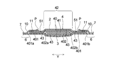
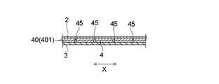
以下、本発明の吸収性物品を、その好ましい一実施形態である生理用ナプキンに基づき図面を参照して説明する。本実施形態のナプキン1は、図1及び図2に示すように、液保持性の吸収体4並びに該吸収体4の肌対向面側に配置された表面シート2及び該吸収体4の非肌対向面側に配置された裏面シート3を具備する吸収性本体5を備え、着用者の前後方向に相当する縦方向Xとこれに直交する横方向Yとを有する。
Hereinafter, the absorbent article of the present invention will be described with reference to the drawings based on a sanitary napkin which is a preferred embodiment thereof. As shown in FIGS. 1 and 2, the napkin 1 of the present embodiment includes a liquid-retaining absorbent body 4, a surface sheet 2 disposed on the skin-facing surface side of the absorbent body 4, and a non-skin of the absorbent body 4. It has an absorptive main body 5 having a back sheet 3 arranged on the opposite surface side, and has a longitudinal direction X corresponding to the wearer's front-rear direction and a transverse direction Y orthogonal thereto.
なお、本明細書において、肌対向面は、吸収性物品又はその構成部材(例えば吸収性本体5)における、吸収性物品の着用時に着用者の肌側に向けられる面であり、非肌対向面は、吸収性物品又はその構成部材における、吸収性物品の着用時に肌側とは反対側(着衣側)に向けられる面である。また、縦方向Xは、吸収性物品(吸収性本体)の長手方向に一致し、横方向Yは、吸収性物品(吸収性本体)の幅方向(長手方向に直交する方向)に一致する。
In addition, in this specification, a skin opposing surface is a surface which faces a wearer's skin side at the time of wear of an absorbent article in an absorbent article or its structural member (for example, absorbent main body 5), and is a non-skin opposing surface Is the surface of the absorbent article or its component that is directed to the side opposite to the skin side (clothing side) when the absorbent article is worn. Further, the longitudinal direction X coincides with the longitudinal direction of the absorbent article (absorbent body), and the lateral direction Y coincides with the width direction (direction orthogonal to the longitudinal direction) of the absorbent article (absorbent body).
吸収性本体5は、着用時に着用者の液排泄部(膣口等)に対向配置される排泄部対向部Bと、着用時に排泄部対向部Bよりも着用者の腹側(前側)に配される前方部Aと、着用時に排泄部対向部Bよりも着用者の背側(後側)に配される後方部Cとを縦方向Xに有している。
The absorptive main body 5 is disposed on the abdomen (front side) of the wearer relative to the excretion part facing part B disposed opposite to the wearer's liquid excretion part (such as the vaginal opening) when worn and the excretion part facing part B when worn. The front portion A and the rear portion C arranged on the back side (rear side) of the wearer rather than the excretory portion facing portion B at the time of wearing are provided in the vertical direction X.
ナプキン1は、吸収性本体5に加えて更に、吸収性本体5における排泄部対向部Bの縦方向Xに沿う両側部それぞれから横方向Yの外方に延出する一対のウイング部7,7を有している。
In addition to the absorbent main body 5, the napkin 1 further includes a pair of wing portions 7, 7 extending outward in the lateral direction Y from both side portions along the vertical direction X of the excretory portion facing portion B of the absorbent main body 5. have.
なお、本発明の吸収性物品において、排泄部対向部は、本実施形態のナプキン1のようにウイング部を有する場合には、吸収性物品の縦方向(吸収性物品の長手方向、図中のX方向)においてウイング部を有する領域(ウイング部の縦方向一方側の付け根と他方側の付け根とに挟まれた領域)である。ウイング部を有しない吸収性物品における排泄部対向部は、吸収性物品が3つ折りの個装形態に折り畳まれた際に生じる、該吸収性物品を横方向(吸収性物品の幅方向、図中のY方向)に横断する2本の折曲線(図示せず)について、該吸収性物品の縦方向の前端から数えて第1折曲線と第2折曲線とに囲まれた領域である。
In the absorbent article of the present invention, when the excretory part facing part has a wing part like the napkin 1 of the present embodiment, the longitudinal direction of the absorbent article (the longitudinal direction of the absorbent article, in the figure) (X direction) is a region having a wing portion (a region sandwiched between a base on one side in the vertical direction of the wing portion and a base on the other side). The excretion part opposing part in the absorbent article which does not have a wing part is the transverse direction (width direction of an absorbent article, in the figure) generated when the absorbent article is folded into a tri-fold individual form. The two folding lines (not shown) crossing in the Y direction) are areas surrounded by the first folding curve and the second folding curve counted from the front end in the longitudinal direction of the absorbent article.
図2に示すように、表面シート2は、吸収体4の肌対向面の全域を被覆し、更に吸収体4の縦方向Xに沿う両側縁から横方向Yの外方に延出している。一方、裏面シート3は、吸収体4の非肌対向面の全域を被覆し、更に吸収体4の縦方向Xに沿う両側縁から横方向Yの外方に延出して、後述するサイドシート10とともに、サイドフラップ部6を形成している。裏面シート3とサイドシート10とは、吸収体4の縦方向Xに沿う両側縁からの延出部において、接着剤、ヒートシール、超音波シール等の公知の接合手段によって互いに接合されている。表面シート2及び裏面シート3それぞれと吸収体4との間は接着剤によって接合されていても良い。
As shown in FIG. 2, the top sheet 2 covers the whole area of the skin-facing surface of the absorbent body 4 and further extends outward in the lateral direction Y from both side edges along the longitudinal direction X of the absorbent body 4. On the other hand, the back sheet 3 covers the entire area of the non-skin facing surface of the absorbent body 4 and further extends outward in the lateral direction Y from both side edges along the longitudinal direction X of the absorbent body 4 to be described later. At the same time, a side flap portion 6 is formed. The back sheet 3 and the side sheet 10 are joined to each other by known joining means such as an adhesive, heat seal, ultrasonic seal, and the like at the extended portions from both side edges along the longitudinal direction X of the absorber 4. The top sheet 2 and the back sheet 3 may be bonded to the absorber 4 with an adhesive.
本実施形態における吸収体4は、図2に示すように、本体吸収性シート401及び中央吸収性シート402が複数層積層されてなる積層構造を有し、図1及び図2に示すように、排泄部対向部Bに多層部42を有している。多層部42は、図2に示すように、吸収体4を構成する吸収性シート401,402の積層枚数が、その周囲に位置する部分より多い部分である。本実施形態における多層部42は、その周囲に位置する部分よりも厚みも厚く、排泄部対向部Bに、表面シート2側(ナプキン1の肌対向面側)に突出した隆起部を形成している。また、吸収体4は、吸収体4の外形を形成する主吸収体40と、主吸収体40の一部に重ねて配された主吸収体40より小型の補助吸収体41とを有している。補助吸収体41は、少なくとも排泄部対向部Bに位置している。
The absorbent body 4 in the present embodiment has a laminated structure in which a main body absorbent sheet 401 and a central absorbent sheet 402 are laminated as shown in FIG. 2, and as shown in FIGS. 1 and 2, The excretory part facing part B has a multilayer part 42. As shown in FIG. 2, the multilayer part 42 is a part where the number of laminated absorbent sheets 401 and 402 constituting the absorbent body 4 is larger than the part located around the multilayered part 42. The multilayer part 42 in this embodiment is thicker than the part located in the circumference | surroundings, and forms the protruding part which protruded in the excretion part opposing part B to the surface sheet 2 side (skin opposing surface side of the napkin 1). Yes. The absorbent body 4 includes a main absorbent body 40 that forms the outer shape of the absorbent body 4, and an auxiliary absorbent body 41 that is smaller than the main absorbent body 40 that is arranged on a part of the main absorbent body 40. Yes. The auxiliary absorber 41 is located at least in the excretory part facing part B.
本実施形態における吸収体4は、吸収性シート401,402の積層構造のみから構成されていることが好ましく、該吸収体4はパルプ等の吸液性繊維の積繊構造を有していないことが好ましい。本発明において、吸収性シートとは、パルプを含む吸収性材料をバインダーなどの接着手段を用いて薄く形成したシート状の吸収構造体を言う。
The absorbent body 4 in the present embodiment is preferably composed only of a laminated structure of absorbent sheets 401 and 402, and the absorbent body 4 does not have a stacked structure of absorbent fibers such as pulp. Is preferred. In the present invention, the absorbent sheet refers to a sheet-like absorbent structure in which an absorbent material containing pulp is thinly formed using an adhesive means such as a binder.
主吸収体40は、パルプを含む本体吸収性シート401の折り畳み構造からなる。詳細には、主吸収体40は、本体吸収性シート401を、縦方向Xに沿って延びる折り線401a,401bの位置で内折りして形成されている。つまり本体吸収性シート401は、両端折りの折り畳み状態になっている。このとき、本体吸収性シート401のうち、内折りされた部位が互いに一部重なるように、折り線401a,401bの位置を調整する。したがって主吸収体40は、本体吸収性シート401からなる2層及び3層の積層構造になっている。
The main absorbent body 40 has a folded structure of a main body absorbent sheet 401 containing pulp. Specifically, the main absorbent body 40 is formed by folding the main body absorbent sheet 401 inwardly at positions of folding lines 401 a and 401 b extending along the vertical direction X. That is, the main body absorbent sheet 401 is folded at both ends. At this time, the positions of the folding lines 401a and 401b are adjusted so that the inwardly folded portions of the main body absorbent sheet 401 partially overlap each other. Therefore, the main absorbent body 40 has a laminated structure of two layers and three layers made of the main body absorbent sheet 401.
一方、補助吸収体41は、パルプを含む中央吸収性シート402の折り畳み構造からなる。詳細には、補助吸収体41は、中央吸収性シート402を、縦方向Xに沿って延びる折り線402aに沿って、該折り線402aよりも外方に位置する部位を内折りする。次に、折り線402bに沿って、該折り線402bよりも外方に位置する部位を、先に折られている部位の側に向けて内折りする。折り線402a及び402bは、中央吸収性シート402の横方向Yの長さを略三等分する位置に形成される。これによって中央吸収性シート402は、巻き三つ折りの折り畳み状態となる。したがって補助吸収体41は、中央吸収性シート402からなる3層の積層構造になっている。
On the other hand, the auxiliary absorbent body 41 has a folded structure of the central absorbent sheet 402 containing pulp. Specifically, the auxiliary absorbent body 41 folds the central absorbent sheet 402 inward along a fold line 402a extending along the longitudinal direction X at a portion located outward from the fold line 402a. Next, along the fold line 402b, the part located outward from the fold line 402b is folded inward toward the part that is folded first. The fold lines 402a and 402b are formed at positions that divide the length in the lateral direction Y of the central absorbent sheet 402 into approximately three equal parts. As a result, the central absorbent sheet 402 is in a folded state with three windings. Therefore, the auxiliary absorbent body 41 has a three-layer structure composed of the central absorbent sheet 402.
図2に示すとおり、巻き三つ折りの折り畳み状態となっている中央吸収性シート402は、両端折りの折り畳み状態になっている本体吸収性シート401の内部に配置されている。つまり、本体吸収性シート401と中央吸収性シート402とは、入れ子の折り畳み構造になっている。その結果、本体吸収性シート401と中央吸収性シート402との積層構造においては、中央吸収性シート402の周縁の少なくとも一部、具体的には該周縁の全域から外方に延出するように本体吸収性シート401が積層されている。なお、補助吸収体41は、上述のとおり排泄部対向部Bに位置しているので、該補助吸収体41を構成する中央吸収性シート402も排泄部対向部Bに位置していることになる。
As shown in FIG. 2, the central absorbent sheet 402 that is folded in a three-fold manner is disposed inside the main body absorbent sheet 401 that is folded in both ends. That is, the main body absorbent sheet 401 and the central absorbent sheet 402 have a nested folding structure. As a result, in the laminated structure of the main body absorbent sheet 401 and the central absorbent sheet 402, it extends outward from at least a part of the peripheral edge of the central absorbent sheet 402, specifically from the entire region of the peripheral edge. A main body absorbent sheet 401 is laminated. In addition, since the auxiliary | assistant absorber 41 is located in the excretion part opposing part B as above-mentioned, the center absorbent sheet 402 which comprises this auxiliary | assistant absorber 41 is also located in the excretion part opposing part B. .
本体吸収性シート401の折り畳み構造からなる主吸収体40は、平面視において角が丸みを帯びた略矩形形状でかつ前方部Aから排泄部対向部Bを経て後方部Cにわたって延びている。一方、中央吸収性シート402の折り畳み構造からなる補助吸収体41は、平面視において略矩形形状であり、排泄部対向部Bからその近傍の後方部Cにわたって配されている。主吸収体40の一部に補助吸収体41を配することで、吸収体4の一部の吸収容量を容易かつ効率的に増大させることができる。補助吸収体41は、折り畳まれた本体吸収性シート401からなる主吸収体40の内部に配置するのに代えて、主吸収体40を構成する本体吸収性シート401の肌対向面側に積層しても良いし、非肌対向面側に積層しても良い。
The main absorbent body 40 having a folded structure of the main body absorbent sheet 401 has a substantially rectangular shape with rounded corners in plan view, and extends from the front part A to the rear part C via the excretory part facing part B. On the other hand, the auxiliary absorbent body 41 having a folded structure of the central absorbent sheet 402 has a substantially rectangular shape in plan view, and is arranged from the excretory part facing part B to the rear part C in the vicinity thereof. By arranging the auxiliary absorber 41 in a part of the main absorber 40, the absorption capacity of a part of the absorber 4 can be easily and efficiently increased. The auxiliary absorbent body 41 is laminated on the skin facing surface side of the main body absorbent sheet 401 constituting the main absorbent body 40, instead of being disposed inside the main absorbent body 40 composed of the folded main body absorbent sheet 401. Alternatively, it may be laminated on the non-skin facing surface side.
吸収性本体5の肌対向面(表面シート2の肌対向面)における縦方向Xに沿う両側部には、図1及び図2に示すように、平面視において吸収体4の縦方向Xに沿う左右両側部に重なるように、一対のサイドシート10,10が吸収性本体5の縦方向Xの略全長にわたって配されている。一対のサイドシート10,10は、それぞれ、排泄部対向部Bに位置する線状の第1接合線11と、該第1接合線11の縦方向Xの前後(前方部A及び後方部C)に位置する線状の第2接合線12とで吸収性本体5(表面シート2)に接合されている。第1接合線11は、平面視において横方向Yの外方に向けて凸の曲線状であり、第2接合線12は、平面視において縦方向に交差するように延びる線状(ジグザグ線状)である。サイドシート10は、撥水性の不織布からなる。このように、サイドシート10が接合線11,12にて吸収性本体5の肌対向面(表面シート2)に接合されていると、図2に示すように、接合線11,12よりも横方向Yの内方に、サイドシート10と表面シート2とで画成される空間部Pが形成される。この空間部Pは、吸収性本体5の横方向Yの中央に向けて開口しているので、横方向Yの中央から外方へ流れる経血等の排泄液は空間部Pに収容されるようになり、結果として排泄液の漏れが効果的に防止される。
As shown in FIG. 1 and FIG. 2, along the longitudinal direction X of the absorbent body 4 in plan view, on both side portions along the longitudinal direction X of the skin facing surface of the absorbent main body 5 (skin facing surface of the topsheet 2). A pair of side sheets 10 and 10 are arranged over substantially the entire length in the longitudinal direction X of the absorbent main body 5 so as to overlap the left and right side portions. The pair of side sheets 10 and 10 are each a linear first joining line 11 located in the excretory part facing part B, and the longitudinal direction X of the first joining line 11 (front part A and rear part C). It joins to the absorptive main body 5 (surface sheet 2) with the linear 2nd joining line 12 located in this. The first joining line 11 has a curved shape that protrudes outward in the lateral direction Y in plan view, and the second joining line 12 has a linear shape (zigzag line shape) that extends in the longitudinal direction in plan view. ). The side sheet 10 is made of a water-repellent nonwoven fabric. Thus, when the side sheet 10 is joined to the skin facing surface (surface sheet 2) of the absorbent main body 5 by the joining lines 11 and 12, as shown in FIG. A space P defined by the side sheet 10 and the top sheet 2 is formed inward in the direction Y. Since the space P is open toward the center in the lateral direction Y of the absorbent main body 5, excretion fluid such as menstrual blood flowing outward from the center in the lateral direction Y seems to be accommodated in the space P. As a result, the leakage of excretory fluid is effectively prevented.
サイドフラップ部6は、図1に示すように、排泄部対向部Bにおいて横方向Yの外方に向かって大きく張り出しており、これにより吸収性本体5の縦方向Xに沿う左右両側に、一対のウイング部7,7が延設されている。また、表面シート2及び裏面シート3は、図1に示すように、吸収体4の縦方向Xの前端及び後端それぞれから縦方向Xの外方に延出し、それらの延出部において、接着剤、ヒートシール、超音波シール等の公知の接合手段によって、互いに接合されてエンドシール部を形成している。
As shown in FIG. 1, the side flap portions 6 project greatly outward in the lateral direction Y at the excretory portion-facing portion B, whereby a pair of side flap portions 6 are provided on both the left and right sides along the longitudinal direction X of the absorbent main body 5. The wing portions 7, 7 are extended. Further, as shown in FIG. 1, the top sheet 2 and the back sheet 3 extend outward in the longitudinal direction X from the front end and the rear end in the longitudinal direction X of the absorbent body 4. The end seal portion is formed by bonding to each other by a known bonding means such as an agent, heat sealing, ultrasonic sealing or the like.
ウイング部7は、ショーツ等の着衣のクロッチ部の非肌対向面側に折り返されて用いられるものである。ウイング部7は、図1に示すように、平面視において、下底(上底よりも長い辺)が吸収性本体5の側部側に位置する略台形形状を有している。ウイング部7の非肌対向面には、該ウイング部7(ナプキン1)をショーツ等の着衣(図示せず)に固定するウイング部粘着部(図示せず)が形成されており、このウイング部粘着部によって、使用時に、着衣のクロッチ部の非肌対向面(外面)側に折り返されたウイング部7を、該クロッチ部に粘着固定できるようになされている。また、吸収性本体5の非肌対向面にも、吸収性本体5を、ショーツ等の着衣に固定するための本体粘着部(図示せず)が形成されている。なお、ナプキン1においては、吸収性本体5とウイング部7との境界線は、ウイング部7の縦方向Xの両付け根を結ぶ直線(図示せず)である。
The wing part 7 is used by being folded back to the non-skin facing surface side of the crotch part of clothes such as shorts. As shown in FIG. 1, the wing portion 7 has a substantially trapezoidal shape in which a lower base (a side longer than the upper base) is positioned on the side of the absorbent main body 5 in a plan view. On the non-skin facing surface of the wing part 7, a wing part adhesive part (not shown) for fixing the wing part 7 (napkin 1) to clothing (not shown) such as shorts is formed. The wing portion 7 that is folded back to the non-skin facing surface (outer surface) side of the crotch portion of the clothes can be adhered and fixed to the crotch portion by the adhesive portion. Moreover, the main body adhesion part (not shown) for fixing the absorptive main body 5 to clothes, such as shorts, is also formed in the non-skin opposing surface of the absorptive main body 5. In the napkin 1, the boundary line between the absorbent main body 5 and the wing portion 7 is a straight line (not shown) that connects the roots in the longitudinal direction X of the wing portion 7.
図示していないが、ナプキン1は、吸収体4と表面シート2との間にセカンドシートを更に具備していることが好ましい。セカンドシートは、その構成繊維が合成繊維である液透過性の繊維シートであることが好ましい。特にセカンドシートが疎水性の合成繊維を親水化処理した繊維で構成されていると、液の拡散性を低く抑えることができる。また、セカンドシートを構成する合成繊維は、拡散性を低く抑えるとともに、機械適合性の観点から、弱親水性である繊維であることが好ましい。セカンドシートは、ポリエチレン、ポリプロピレン、ポリエチレンテレフタレート、ポリブチレンテレフタレートなどのポリエステル、ナイロン-6やナイロン-66などのポリアミド等の樹脂からなる繊維を単独で、又は2種以上を混合して形成することができる。なお、ここで言う混合とは、融点の異なる2種以上の樹脂を、芯鞘型複合繊維やサイドバイサイド型複合繊維にして用いることを含む。
Although not shown, it is preferable that the napkin 1 further includes a second sheet between the absorber 4 and the top sheet 2. The second sheet is preferably a liquid-permeable fiber sheet whose constituent fiber is a synthetic fiber. In particular, when the second sheet is composed of fibers obtained by hydrophilizing hydrophobic synthetic fibers, the liquid diffusibility can be kept low. The synthetic fiber constituting the second sheet is preferably a weakly hydrophilic fiber from the viewpoint of mechanical compatibility while keeping the diffusibility low. The second sheet may be formed of fibers made of a resin such as polyester such as polyethylene, polypropylene, polyethylene terephthalate, polybutylene terephthalate, or polyamide such as nylon-6 or nylon-66, or a mixture of two or more kinds. it can. In addition, the mixing said here includes using 2 or more types of resin from which melting | fusing point differs as a core-sheath-type composite fiber or a side-by-side type composite fiber.
セカンドシートは、高い透過性と適度な拡散性を有するシートであるため、その厚みが0.15mm以上であることが好ましく、0.2mm以上であることが更に好ましい。また0.4mm以下であることが好ましく、0.3mm以下であることが更に好ましい。厚みは、装着状態を考慮した観点から、0.5kPa荷重下において測定する。
Since the second sheet is a sheet having high permeability and moderate diffusivity, the thickness is preferably 0.15 mm or more, and more preferably 0.2 mm or more. Moreover, it is preferable that it is 0.4 mm or less, and it is still more preferable that it is 0.3 mm or less. The thickness is measured under a 0.5 kPa load from the viewpoint of considering the wearing state.
セカンドシートとしては、交差した合成繊維どうしの互いの交点がエアスルー方式の熱融着によって接合されているエアスルー不織布を好ましく用いることができる。なお、エアスルー不織布以外にも、ポイントボンド不織布、スパンボンド不織布、スパンレース不織布等であっても良い。セカンドシートがエアスルー不織布である場合には、その坪量は、15g/m2以上40g/m2以下であることが好ましい。
As the second sheet, an air-through nonwoven fabric in which the intersecting points of the crossed synthetic fibers are joined by air-through heat fusion can be preferably used. In addition to the air-through nonwoven fabric, a point bond nonwoven fabric, a spunbond nonwoven fabric, a spunlace nonwoven fabric, or the like may be used. When the second sheet is an air-through nonwoven fabric, the basis weight is preferably 15 g / m 2 or more and 40 g / m 2 or less.
表面シート2とセカンドシートとは、部分的に固着されていることが好ましい。このことにより、表面シート2の浮きを抑制し、表面シート2とセカンドシートの密着性が向上し、液が移行しやすくなる。同様の理由で、セカンドシートと吸収体4との間も部分的に固着されていることが好ましい。部分的に固着とは、点や線からなる固着部を有し、該固着部がシート面全体に分布しており、均一に分布する必要はないが、固着するシート間を全面固着するのではないことを意味する。該固着部の面積は被固着シート全面積の10%以上70%以下程度が好ましい。具体的には、接着剤を間欠的に塗布したり、間欠的にヒートシールを施したりして、表面シート2とセカンドシートとを部分的に固着している。接着剤を間欠的に塗布する場合には、接着剤を、公知の手段、例えば、スロットコートガンを用いて間欠的に塗布したり、スパイラルスプレーガンを用いて螺旋状に塗布したり、スプレーガンを用いて間欠的に霧状に塗布したり、ドットガンを用いてドット状に塗布したりして、表面シート2とセカンドシートとの間に体液の透過性を維持した状態で、表面シート2とセカンドシートとを部分的に接着する。塗布する接着剤としては、例えば、ホットメルト接着剤が好ましく用いられる。
It is preferable that the top sheet 2 and the second sheet are partially fixed. Thereby, the float of the surface sheet 2 is suppressed, the adhesion between the surface sheet 2 and the second sheet is improved, and the liquid is easily transferred. For the same reason, it is preferable that the second sheet and the absorber 4 are also partially fixed. Partially fixed means that there are fixed portions consisting of dots and lines, and the fixed portions are distributed over the entire sheet surface and do not need to be evenly distributed. Means no. The area of the fixing portion is preferably about 10% or more and 70% or less of the total area of the adherend sheet. Specifically, the topsheet 2 and the second sheet are partially fixed by applying an adhesive intermittently or intermittently heat-sealing. When the adhesive is applied intermittently, the adhesive is applied intermittently using a known means such as a slot coat gun, spirally applied using a spiral spray gun, or spray gun. The surface sheet 2 is applied in the form of a mist intermittently using a dot gun or in the form of dots using a dot gun to maintain the fluid permeability between the surface sheet 2 and the second sheet. And the second sheet are partially bonded. As the adhesive to be applied, for example, a hot melt adhesive is preferably used.
ホットメルト接着剤としては、スチレン系、オレフィン系等が挙げられる。スチレン系ホットメルト接着剤としては、スチレン-ブタジエン-スチレン共重合体(SBS)、スチレン-イソプレン-スチレン共重合体(SIS)、SBSの水素添加物であるスチレン-エチレン-ブチレン-スチレン共重合体(SEBS)、及びこれらの2種以上をブレンドしたブレンド系ホットメルト接着剤を使用することができる。これらの中でも、タック力と凝集力のバランスが取りやすい観点から、特にSISとSBSとのブレンド系ホットメルト接着剤、又はSISとSEBSのブレンド系ホットメルト接着剤が、本発明で好ましく用いられる。ホットメルト接着剤の塗布量は、3g/m2以上10g/m2以下であることが好ましい。
Examples of the hot melt adhesive include styrene and olefin. Styrene-based hot melt adhesives include styrene-butadiene-styrene copolymer (SBS), styrene-isoprene-styrene copolymer (SIS), and styrene-ethylene-butylene-styrene copolymer that is a hydrogenated product of SBS. (SEBS) and blended hot melt adhesives in which two or more of these are blended can be used. Among these, from the viewpoint of easily balancing the tack force and the cohesive force, a blended hot melt adhesive of SIS and SBS or a blended hot melt adhesive of SIS and SEBS is particularly preferably used in the present invention. The application amount of the hot melt adhesive is preferably 3 g / m 2 or more and 10 g / m 2 or less.
間欠的にヒートシールを施す場合には、例えば、複数個の凸部を有する熱エンボスロールと平坦ロールとを用いて、表面シート2とセカンドシートとの積層シートを熱エンボスロールと平坦ロールとの間に搬送し、エンボスすることにより、表面シート2とセカンドシートとを部分的に融着する。融着することにより形成される複数個の融着点どうしの間隔は、表面シート2とセカンドシートとの間に適度な密着性を持たせて体液の透過性を維持する観点から、5mm以上15mm以下であることが好ましい。
When intermittently heat-sealing, for example, using a hot embossing roll having a plurality of convex portions and a flat roll, a laminated sheet of the top sheet 2 and the second sheet is made up of a hot embossing roll and a flat roll. The top sheet 2 and the second sheet are partially fused by being conveyed in between and embossed. The interval between the plurality of fusion points formed by fusing is 5 mm or more and 15 mm from the viewpoint of maintaining appropriate fluid adhesion between the top sheet 2 and the second sheet and maintaining the fluid permeability. The following is preferable.
図1及び図2に示すように、吸収性本体5の肌対向面(表面シート2の肌対向面)には、表面シート2及び吸収体4が裏面シート3側に向かって一体的に凹陥してなる線状溝が形成されており、該線状溝は、排泄部対向部Bにおいて縦方向Xに延びる縦溝51と、前方部A及び後方部Cにおいて、それぞれ横方向Yに延びるように形成された第1及び第2の横溝52,53とを含む。線状溝は、熱を伴うか又は伴わない圧搾加工、あるいは超音波エンボス等のエンボス加工により常法に従って形成することができる。線状溝においては、表面シート2及び吸収体4との間が、図示しないが、接着剤を介して圧着されるか、あるいは熱融着等により一体化している。
As shown in FIG.1 and FIG.2, the surface sheet 2 and the absorber 4 are dented integrally on the skin opposing surface (skin opposing surface of the surface sheet 2) of the absorptive main body 5 toward the back surface sheet 3 side. The linear groove is formed so as to extend in the horizontal direction Y in the vertical groove 51 extending in the vertical direction X in the excretory part facing part B and in the front part A and the rear part C, respectively. The first and second lateral grooves 52 and 53 are formed. A linear groove | channel can be formed in accordance with a conventional method by pressing process with or without heat, or embossing, such as ultrasonic embossing. In the linear groove, the surface sheet 2 and the absorber 4 are not shown in the figure, but are bonded by an adhesive or integrated by thermal fusion or the like.
このような線状溝は、吸収体4の平面方向の液の拡散を抑制して、ナプキン1の周囲から液漏れを効果的に防止することができる。線状溝の幅(長さ方向と直交する方向の長さ)及び深さは、この種の吸収性物品における線状溝と同様に設定すれば良い。また、線状溝における「線状」とは、溝(凹陥部)の形状が平面視において直線に限られず、曲線を含み、各線は、連続線でも破線でも良い。例えば、線状溝は、不連続な多数の点エンボスのなす列から構成されていても良い。なお、本実施形態のナプキン1は、図1に示すように、吸収性本体5を横方向Yに二分する中心線(図示せず)に対して左右対称に形成されている。
Such a linear groove can prevent liquid leakage from the periphery of the napkin 1 by suppressing the diffusion of the liquid in the planar direction of the absorber 4. What is necessary is just to set the width | variety (length of the direction orthogonal to a length direction) and depth of a linear groove similarly to the linear groove in this kind of absorbent article. In addition, “linear” in the linear groove is not limited to a straight line in the plan view, but includes a curved line, and each line may be a continuous line or a broken line. For example, the linear groove may be composed of a row formed by a large number of discontinuous point embosses. In addition, the napkin 1 of this embodiment is formed left-right symmetrically with respect to the centerline (not shown) which bisects the absorptive main body 5 to the horizontal direction Y, as shown in FIG.
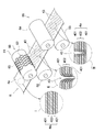
本実施形態のナプキン1は、図1及び図3に示すように、吸収体4が、排泄部対向部Bに、縦方向Xに沿う縦スリット43が複数、分散した状態に形成された排泄部スリット領域Sを有している。排泄部スリット領域Sは、中央スリット領域S1及び側部スリット領域S2から構成されている。中央スリット領域S1は、排泄部対向部Bにおける吸収体4の横方向Yの中央部に位置している。中央スリット領域S1は、多層部42、すなわち本体吸収性シート401と中央吸収性シート402とが積層された部位と略一致している。中央スリット領域S1よりも、横方向Yの外方には側部スリット領域S2が位置している。側部スリット領域S2は、吸収体4が本体吸収性シート401のみで形成されている部位と略一致している。
As shown in FIGS. 1 and 3, the napkin 1 of the present embodiment has an excretory part in which the absorber 4 is formed in a state in which a plurality of vertical slits 43 along the vertical direction X are dispersed in the excretory part facing part B. A slit region S is provided. The excretory part slit area | region S is comprised from the center slit area | region S1 and the side part slit area | region S2. The central slit region S1 is located at the central portion in the lateral direction Y of the absorbent body 4 in the excretory portion facing portion B. The central slit region S1 substantially coincides with the multilayer portion 42, that is, the portion where the main body absorbent sheet 401 and the central absorbent sheet 402 are laminated. The side slit region S2 is located outside the central slit region S1 in the lateral direction Y. The side slit region S2 substantially coincides with a portion where the absorbent body 4 is formed only by the main body absorbent sheet 401.
排泄部スリット領域Sにおける縦スリット43は、縦方向X及び横方向Yの両方向に分散した状態に形成されている。縦スリット43は、図2に示すように、吸収体4をその厚み方向に向けて切り込むことで形成されており、吸収体4を構成する吸収性シート401,402の積層構造を貫通していることが好ましい。縦スリット43は、吸収体4の上下に配される表面シート2及び裏面シート3には、形成されておらず、表面シート2と吸収体4との間に配されることのある不織布からなる中間シートにも形成されていないことが好ましい。
The vertical slits 43 in the excretion part slit region S are formed in a state dispersed in both the vertical direction X and the horizontal direction Y. As shown in FIG. 2, the vertical slit 43 is formed by cutting the absorber 4 in the thickness direction, and penetrates the laminated structure of the absorbent sheets 401 and 402 constituting the absorber 4. It is preferable. The vertical slits 43 are not formed on the top sheet 2 and the back sheet 3 disposed above and below the absorbent body 4 and are made of a nonwoven fabric that may be disposed between the top sheet 2 and the absorbent body 4. It is preferable that the intermediate sheet is not formed.
各縦スリット43は個々に独立しており、隣り合う縦スリット43どうしの間には非スリット部43’が位置している。そして、各縦スリット43は、その周囲の全域が非スリット部43’によって囲まれている。
Each vertical slit 43 is individually independent, and a non-slit portion 43 ′ is located between adjacent vertical slits 43. Each vertical slit 43 is surrounded by a non-slit portion 43 ′ around the entire periphery.
縦スリット43は、上述のとおり、吸収体4をその厚み方向にわたって切り込みを入れて形成されたものであり、実質的に幅を有していない切り込みから形成されているか、又は好ましくは1.5mm以下の細幅の空間となっている。縦スリット43が幅を有している場合、当該幅とは、縦スリット43の延びる方向と直交する方向における該縦スリット43の長さのことを言う。
As described above, the vertical slit 43 is formed by cutting the absorber 4 in the thickness direction, and is formed from a cut having substantially no width, or preferably 1.5 mm. It has the following narrow space. When the vertical slit 43 has a width, the width means the length of the vertical slit 43 in a direction orthogonal to the direction in which the vertical slit 43 extends.
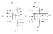
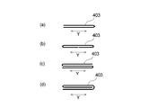
図3(a)及び図3(b)に示すように、吸収体4には、横方向Yに離間した複数本の縦スリット43からなるスリット列R1,R2が、ナプキン1の縦方向Xに複数列形成されている。図3(a)及び図3(b)には、横方向Yに離間した2本の縦スリット43からなるスリット列R1と、横方向Yに離間した3本の縦スリット43からなるスリット列R2とが、縦方向Xに交互に形成されている例を示したが、排泄部スリット領域Sには、最低、横方向Yに離間した2本の縦スリット43からなるスリット列が縦方向Xに2列形成されていれば良い。ただし、スリット列は、縦方向Xに3列以上形成されていることが好ましく、4列以上がより好ましく、5列以上が更に好ましい。また、個々のスリット列に含まれる横方向Xに離間した縦スリットの本数は、好ましくは2本以上であり、より好ましくは3本以上、更に好ましくは4本以上である。
As shown in FIG. 3A and FIG. 3B, the absorber 4 has slit rows R <b> 1 and R <b> 2 including a plurality of vertical slits 43 spaced in the horizontal direction Y in the vertical direction X of the napkin 1. Multiple rows are formed. 3A and 3B, a slit row R1 composed of two vertical slits 43 spaced in the horizontal direction Y and a slit row R2 composed of three vertical slits 43 spaced in the horizontal direction Y are shown. However, in the excretion part slit region S, a slit row composed of at least two vertical slits 43 spaced apart in the horizontal direction Y is arranged in the vertical direction X. It is sufficient that two rows are formed. However, the slit rows are preferably formed in 3 or more rows in the vertical direction X, more preferably 4 rows or more, and even more preferably 5 rows or more. Further, the number of vertical slits separated in the horizontal direction X included in each slit row is preferably 2 or more, more preferably 3 or more, and further preferably 4 or more.
ナプキン1の縦方向Xに隣り合うスリット列間には間隔を有しないことが好ましい。隣り合うスリット列間に間隔Pを有しないという表現には、図3(a)に示すように、隣り合うスリット列のスリット43の端部どうしの位置が一致している場合と、図3(b)に示すように、隣り合うスリット列が、縦方向Xにおいて一部重複している場合とが含まれる。図3(b)に示すように、2本のスリット列を互いの一部を重複させた状態で縦方向Xに配置する場合、その重複させる長さL1は、スリット列を構成する縦スリットの同方向Xの長さL2の20%以下であることが好ましく、10%以下であることが好ましい。
It is preferable that there is no space between adjacent slit rows in the longitudinal direction X of the napkin 1. In the expression that there is no interval P between adjacent slit rows, as shown in FIG. 3A, the positions of the ends of the slits 43 of the adjacent slit rows coincide with each other, as shown in FIG. As shown in b), the case where adjacent slit rows partially overlap in the vertical direction X is included. As shown in FIG. 3 (b), when two slit rows are arranged in the vertical direction X with a part of each other overlapping, the overlapping length L1 is the length of the vertical slits constituting the slit row. It is preferably 20% or less of the length L2 in the same direction X, and preferably 10% or less.
図3(a)及び図3(b)に示すように、ナプキン1の縦方向Xに隣り合うスリット列のスリットの位置は、ナプキン1の横方向Yにずれている。詳細には、縦方向Xに隣り合う2つのスリット列R1,R2における縦スリット43は、一方のスリット列R1のスリット43が、他方のスリット列R2のスリット43間の中央部に位置することが好ましいが、一方のスリット列R1のスリット43が、他方のスリット列R2のスリット43間におけるいずれか一方の側に偏倚させて形成されていても良い。
As shown in FIGS. 3A and 3B, the positions of the slits in the slit rows adjacent in the longitudinal direction X of the napkin 1 are shifted in the lateral direction Y of the napkin 1. Specifically, the vertical slits 43 in the two slit rows R1 and R2 adjacent to each other in the vertical direction X are such that the slit 43 of one slit row R1 is located at the center between the slits 43 of the other slit row R2. Although it is preferable, the slit 43 of one slit row R1 may be formed so as to be biased to one side between the slits 43 of the other slit row R2.
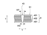
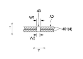
図4には、中央スリット領域S1に形成された縦スリット43及びその近傍の部位における吸収体の縦断面図が示されている。図5は、側部スリット領域S2に形成された縦スリット43及びその近傍の部位における吸収体の縦断面図である。図4に示す中央スリット領域S1においては、中央吸収性シート402が折り畳まれた3層構造部位と、該3層構造部位の上下に位置する本体吸収性シート401,401とからなる5層構造の積層構造に縦スリット43が形成されている。縦スリット43は、5層構造の積層構造をその厚み方向全域にわたって貫通している。一方、図5に示す側部スリット領域S2においては、本体吸収性シート401が折り畳まれた2層の積層構造に縦スリット43が形成されている。縦スリット43は、2層構造の積層構造をその厚み方向全域にわたって貫通している。
FIG. 4 shows a longitudinal sectional view of the absorbent body in the longitudinal slit 43 formed in the central slit region S1 and in the vicinity thereof. FIG. 5 is a longitudinal sectional view of the absorbent body in the longitudinal slit 43 formed in the side slit region S2 and a portion in the vicinity thereof. In the central slit region S1 shown in FIG. 4, a five-layer structure composed of a three-layer structure portion in which the central absorbent sheet 402 is folded and main body absorbent sheets 401 and 401 positioned above and below the three-layer structure portion. A vertical slit 43 is formed in the laminated structure. The vertical slit 43 penetrates the laminated structure of the five-layer structure over the entire thickness direction. On the other hand, in the side slit region S <b> 2 shown in FIG. 5, the vertical slit 43 is formed in a two-layer laminated structure in which the main body absorbent sheet 401 is folded. The vertical slit 43 penetrates the laminated structure of the two-layer structure over the entire region in the thickness direction.
中央スリット領域S1を構成する5層構造の積層構造においては、図4に示すとおり、該積層構造を形成する複数層の吸収性シート間の一部が、縦スリット43が形成された部位において非接合状態になっている。「吸収性シート間が非接合状態になっている」とは、厚み方向において隣り合う吸収性シートどうしが、圧着、接着、融着等の各種の接合手段のいずれによっても接合されていないことを言う。図4においては、厚み方向において隣り合うすべての吸収性シートの間が非接合状態になっている状態が示されている。同図においては、吸収性シートの間が非接合状態になっていることを視覚的に表現することを目的として、吸収性シートどうしの間に空隙を設けているが(図5においても同様である。)、実際の積層構造において、該空隙は形成されていても良く、あるいは形成されていなくても良い。液を繰り返し吸収するときの液の保持容量を増大させて吸収速度の低下を防止する観点からは、吸収性シートどうしの間に空隙が形成されていることが好ましい。また、図4においては、厚み方向において隣り合うすべての吸収性シートの間が非接合状態になっているが、隣り合う吸収性シートの少なくとも1箇所において、該吸収性シートどうしが非接合状態になっていれば良い。
In the laminated structure of the five-layer structure that constitutes the central slit region S1, as shown in FIG. 4, a part between the plurality of absorbent sheets that form the laminated structure is not part of the portion where the vertical slits 43 are formed. Joined state. “Absorbent sheets are in a non-bonded state” means that adjacent absorbent sheets in the thickness direction are not bonded by any of various bonding means such as pressure bonding, adhesion, and fusion. To tell. FIG. 4 shows a state where all the absorbent sheets adjacent in the thickness direction are not joined. In the figure, a gap is provided between the absorbent sheets for the purpose of visually expressing that the absorbent sheets are in a non-bonded state (the same applies to FIG. 5). In the actual laminated structure, the gap may be formed or may not be formed. From the viewpoint of increasing the liquid holding capacity when repeatedly absorbing the liquid and preventing a decrease in the absorption rate, it is preferable that a gap is formed between the absorbent sheets. Moreover, in FIG. 4, between all the absorptive sheets adjacent in the thickness direction is in a non-joined state, but the absorptive sheets are in a non-joined state in at least one location of the adjacent absorbent sheets It only has to be.
吸収性シートは、巨視的には平坦な形状をしているが、微視的には該吸収性シートの表面は微細な凹凸形状となっているので、吸収性シートを重ね合わせる操作を行うだけで、吸収性シート間に空隙が生じる。この空隙は、吸収性シートの積層構造を意図的に圧縮しない限り維持される。
The absorbent sheet has a macroscopically flat shape, but microscopically, the surface of the absorbent sheet has a fine concavo-convex shape, so only the operation of overlapping the absorbent sheets is performed. Thus, a gap is generated between the absorbent sheets. This void is maintained unless the laminated structure of the absorbent sheet is intentionally compressed.
厚み方向において隣り合う吸収性シートが、縦スリット43が形成された部位において非接合状態になっていることで、ナプキン1に排泄された液が表面シート2を通じて吸収体4に到達して縦スリット43内に流入したときに、該液が、縦スリット43の内面を通じて円滑に吸収体4の平面方向に拡散するようになる。特に、厚み方向において隣り合う吸収性シートどうしの間においては、毛細管現象によって液が引き込まれやすい状態になっているので、平面方向への液の拡散が一層起こりやすくなる。その結果、液の吸収速度が速くなる。
The absorbent sheet adjacent in the thickness direction is in a non-bonded state at the site where the vertical slit 43 is formed, so that the liquid excreted in the napkin 1 reaches the absorber 4 through the top sheet 2 and the vertical slit When flowing into 43, the liquid smoothly diffuses in the plane direction of the absorber 4 through the inner surface of the vertical slit 43. In particular, between the absorbent sheets adjacent in the thickness direction, the liquid is likely to be drawn by capillary action, so that the liquid is more easily diffused in the plane direction. As a result, the liquid absorption rate is increased.
中央スリット領域S1と同様に、側部スリット領域S2においても、該側部スリット領域S2を構成する2層構造の積層構造では、該積層構造を形成する2層の吸収性シート間が、縦スリット43が形成された部位において非接合状態になっている。したがって側部スリット領域S2においても、中央スリット領域S1と同様の機序によって液の吸収速度が速くなる。
Similarly to the central slit region S1, also in the side slit region S2, in the laminated structure of the two-layer structure that constitutes the side slit region S2, there is a vertical slit between the two absorbent sheets that form the laminated structure. In a portion where 43 is formed, it is in a non-bonded state. Therefore, also in the side slit region S2, the liquid absorption speed is increased by the same mechanism as in the central slit region S1.
図4及び図5に示すように、縦スリット43の横方向Yの長さを、吸収体4の厚み方向Tに沿って見たとき、表面シート側における長さW1の方が、裏面シート側における長さW2よりも長くなっている。図4及び図5では、縦スリット43の横方向Yの長さは、表面シート側から裏面シート側に向けて連続的に漸減している状態が示されている。しかし、縦スリット43の横方向Yの長さは、このように変化することを要せず、例えば表面シート側から裏面シート側に向けてステップ状に減少していても良い。表面シート側における縦スリット43の長さW1の方が、裏面シート側における長さW2よりも長くなっていることで、縦スリット43に液を受け入れやすくなり、そのことによっても液の吸収速度が速くなる。また、縦スリット43がこのような構造を有していることで、ナプキン1の装着状態において、該ナプキン1に加わった外力が吸収体4の裏面シート側に伝達されにくくなり、ナプキン1を下着に安定的に固定できるようになる。外力が吸収体4の裏面シート側に伝達されにくくなることは、吸収体4の裏面シート側の平坦な形状が維持されることにもつながり、そのことによってもナプキン1を下着に安定的に固定できるようになる。これらの結果、ナプキン1に外力が加わっても、ナプキン1が適正な装着位置からずれにくくなり、それに起因して吸収性の低下や装着感の低下が効果的に防止される。
As shown in FIGS. 4 and 5, when the length of the vertical slit 43 in the horizontal direction Y is viewed along the thickness direction T of the absorbent body 4, the length W1 on the top sheet side is closer to the back sheet side. Is longer than the length W2. 4 and 5 show a state in which the length in the horizontal direction Y of the vertical slit 43 is gradually reduced from the top sheet side to the back sheet side. However, the length of the vertical slit 43 in the horizontal direction Y does not need to be changed in this way, and may be decreased stepwise from the top sheet side to the back sheet side, for example. The length W1 of the vertical slit 43 on the top sheet side is longer than the length W2 on the back sheet side, so that the liquid can be easily received in the vertical slit 43, which also increases the liquid absorption rate. Get faster. Further, since the vertical slit 43 has such a structure, the external force applied to the napkin 1 is not easily transmitted to the back sheet side of the absorbent body 4 when the napkin 1 is attached, and the napkin 1 is attached to the underwear. Can be fixed stably. The fact that the external force is less likely to be transmitted to the back sheet side of the absorber 4 also leads to the maintenance of the flat shape of the absorber 4 on the back sheet side, which also stably fixes the napkin 1 to the undergarment. become able to. As a result, even if an external force is applied to the napkin 1, the napkin 1 is not easily displaced from the proper mounting position, and as a result, a decrease in absorbability and a decrease in mounting feeling are effectively prevented.
吸収体4の厚み方向Tに沿った縦スリット43の断面形状は、マイクロスコープ(例えばKEYENCE社製VHX-1000)を用いて20~100倍の倍率で観察することができる。吸収体4の厚み方向Tに沿った断面は、例えば吸収体4をフェザー社製刃剃刀で切断することで形成することができる。上述したW1とW2との比であるW1/W2は5以上であることが好ましく、10以上であることが更に好ましい。またW1/W2は80以下であることが好ましく、60以下であることが更に好ましい。例えばW1/W2は5以上80以下であることが好ましく、10以上60以下であることが更に好ましい。
The cross-sectional shape of the vertical slit 43 along the thickness direction T of the absorber 4 can be observed at a magnification of 20 to 100 times using a microscope (for example, VHX-1000 manufactured by KEYENCE). The cross section along the thickness direction T of the absorber 4 can be formed, for example, by cutting the absorber 4 with a blade razor manufactured by Feather Corporation. W1 / W2, which is the ratio of W1 to W2 described above, is preferably 5 or more, and more preferably 10 or more. Further, W1 / W2 is preferably 80 or less, and more preferably 60 or less. For example, W1 / W2 is preferably 5 or more and 80 or less, and more preferably 10 or more and 60 or less.
縦スリット43が形成されている部位においては、該縦スリット近傍における吸収性シートの密度が、先に述べた非スリット部43’における該吸収性シートの密度よりも大きくなっていることが好ましい。こうすることで、縦スリット43内に流入した液が、毛細管力の作用によって一層素早く吸収性シートどうしの間に引き込まれやすくなる。この効果を一層顕著なものとする観点から、縦スリット43近傍における吸収性シートの密度は、非スリット部43における該吸収性シートの密度の1.05倍以上であることが好ましく、1.2倍以上であることが更に好ましい。また、2倍以下であることが好ましく、1.8倍以下であることが更に好ましい。例えば、縦スリット43近傍における吸収性シートの密度は、非スリット部43における該吸収性シートの密度の1.05倍以上2倍以下であることが好ましく、1.2倍以上1.8倍以下であることが更に好ましい。
In the portion where the vertical slit 43 is formed, it is preferable that the density of the absorbent sheet in the vicinity of the vertical slit is larger than the density of the absorbent sheet in the non-slit portion 43 ′ described above. By carrying out like this, the liquid which flowed in in the vertical slit 43 becomes easy to be drawn in between absorbent sheets more rapidly by the effect | action of capillary force. From the viewpoint of making this effect more prominent, the density of the absorbent sheet in the vicinity of the longitudinal slit 43 is preferably 1.05 times or more the density of the absorbent sheet in the non-slit portion 43, 1.2 More preferably, it is twice or more. Further, it is preferably 2 times or less, and more preferably 1.8 times or less. For example, the density of the absorbent sheet in the vicinity of the longitudinal slit 43 is preferably 1.05 to 2 times the density of the absorbent sheet in the non-slit portion 43, and is 1.2 to 1.8 times. More preferably.
前記の密度は、以下のようにして測定することができる。縦スリット近傍、及び非スリット部43’ における吸収性シートの密度は、それぞれ、縦スリット近傍の吸収性シート及び非スリット部43’の吸収性シートを、幅3mm、長さ20mmの大きさの試験片に切り出し、試験片の幅方向中央部における厚みを非接触式レーザー変位計(KEYENCE社製、変位計 LK-GD500及びレーザーヘッド LK-G30)を用いて測定し、また試験片の質量を電子天秤(A&D社製電子天秤GR-300、精度:小数点以下4桁)を用いて測定し、測定された厚みから体積を算出し、質量を体積で除すことで算出した。
The density can be measured as follows. The density of the absorbent sheet in the vicinity of the longitudinal slit and in the non-slit portion 43 ′ was determined by testing the absorbent sheet in the vicinity of the longitudinal slit and the absorbent sheet in the non-slit portion 43 ′ with a width of 3 mm and a length of 20 mm, respectively. Cut into pieces and measure the thickness of the test piece in the center in the width direction using a non-contact type laser displacement meter (manufactured by KEYENCE, displacement gauge LK-GD500 and laser head LK-G30). Measurement was performed using a balance (Electronic balance GR-300 manufactured by A & D, accuracy: 4 digits after the decimal point), the volume was calculated from the measured thickness, and the mass was divided by the volume.
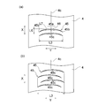
図1に戻ると、同図に示すとおり、吸収体4は、排泄部対向部Bより後方に位置する後方部Cに、ナプキン1の縦方向Xと交差する方向へ長手方向を有するように延びる複数本の後方スリット45を有する。この後方スリット45は、図1(b)、図6及び図7(a)に示すように、スリット45の長手方向の中央部45aの位置が、該長手方向の両端部45b,45bの位置よりも前方部A側に位置する平面視形状を有しており、より好ましくは、前方部A側に向かって凸に湾曲した平面視形状を有している。また、後方スリット45は、吸収性物品の縦方向Xに間隔を開けて複数本形成されている。
Returning to FIG. 1, as shown in FIG. 1, the absorbent body 4 extends at a rear part C located behind the excretory part facing part B so as to have a longitudinal direction in a direction intersecting the longitudinal direction X of the napkin 1. A plurality of rear slits 45 are provided. As shown in FIGS. 1 (b), 6 and 7 (a), the rear slit 45 has a position of the central portion 45a in the longitudinal direction of the slit 45 from the positions of both end portions 45b and 45b in the longitudinal direction. Also has a plan view shape located on the front portion A side, and more preferably has a plan view shape curved convexly toward the front portion A side. Moreover, the back slit 45 is formed in multiple numbers at intervals in the longitudinal direction X of the absorbent article.
また、図1(b)に示すように、後方スリット45で形成される後方スリット領域S3の前記横方向Yの長さL3が、排泄部スリット領域Sの同方向Yの長さL4より短い。図1(b)には、排泄部スリット領域Sを、縦方向X及び横方向Yにいずれについても、見やすさの観点から便宜的に、縦スリット43が分布する範囲よりやや広い範囲として示してある。しかし、本発明における排泄部スリット領域Sは、縦スリット43が分布する範囲であり、その横方向Yの長さL4は、図1(b)に示すとおり、横方向Yの両端に位置する縦スリット44の外縁間の距離である。
Further, as shown in FIG. 1B, the length L3 in the lateral direction Y of the rear slit region S3 formed by the rear slit 45 is shorter than the length L4 in the same direction Y of the excretory slit region S. In FIG. 1 (b), the excretory part slit region S is shown as a range slightly wider than the range in which the vertical slits 43 are distributed from the viewpoint of easiness to see in both the vertical direction X and the horizontal direction Y. is there. However, the excretion portion slit region S in the present invention is a range in which the vertical slits 43 are distributed, and the length L4 in the horizontal direction Y is the vertical length located at both ends in the horizontal direction Y as shown in FIG. This is the distance between the outer edges of the slits 44.
また、後方スリット45で形成される後方スリット領域S3は、縦方向Xに沿う2辺及び横方向Yに沿う2辺を有する長方形であって、後方スリット45の全体(複数本ある場合にはその全部)を囲む長方形のうち最小のものの内側の領域である。後方スリット領域S3についても、図1(b)には、見やすさ等の観点から便宜的に、やや広い範囲として示されている。図7(b)に示すように、後方スリット45が、横方向Yの位置をずらして縦方向Xに複数形成されている場合、後方スリット領域S3の横方向Yの長さL3は、最も外側に位置する端部どうし間の距離とする。
In addition, the rear slit region S3 formed by the rear slit 45 is a rectangle having two sides along the vertical direction X and two sides along the horizontal direction Y. This is the area inside the smallest rectangle that encloses all). The rear slit region S3 is also shown in FIG. 1 (b) as a slightly wide range for convenience from the viewpoint of ease of viewing. As shown in FIG. 7B, when a plurality of the rear slits 45 are formed in the vertical direction X with the horizontal direction Y shifted, the length L3 in the horizontal direction Y of the rear slit region S3 is the outermost side. The distance between the ends located at.
本実施形態のナプキン1では、図7(a)に示すように、吸収体4の横方向長さを二等分する中心位置4cと後方スリット45の長手方向長さを二等分する中心位置45cとがほぼ一致するように配されている。ここで「ほぼ一致」とは、吸収体4の横方向長さの10%の長さ分、吸収体4の中心位置4cと後方スリットの中心位置45cがずれていても良いことを意味する。
In the napkin 1 of the present embodiment, as shown in FIG. 7A, the center position 4 c that bisects the lateral length of the absorber 4 and the center position that bisects the longitudinal length of the rear slit 45. 45c is arranged so as to substantially match. Here, “substantially coincide” means that the center position 4c of the absorber 4 and the center position 45c of the rear slit may be shifted by a length of 10% of the lateral length of the absorber 4.
また、複数の後方スリット45,45各々について、長手方向の長さはほぼ同じである。ここで「略同じ」とは、その長さの差が、後方スリット領域S3の横方向Yの長さL3の5%以内に収まっていることを意味する。更に、複数の後方スリット45,45各々は、中心位置45cがほぼ一致している。ここで「ほぼ一致」とは、吸収体4の横方向長さの5%の長さ分、ずれていても良いことを意味する。
Further, the lengths in the longitudinal direction of the plurality of rear slits 45 are substantially the same. Here, “substantially the same” means that the difference in length is within 5% of the length L3 in the lateral direction Y of the rear slit region S3. Further, the center positions 45c of the plurality of rear slits 45, 45 substantially coincide with each other. Here, “substantially match” means that the absorber 4 may be displaced by a length of 5% of the lateral length.
後方スリット領域S3においては、先に述べた排泄部スリット領域Sに形成された縦スリット43と同様に、積層構造を形成する2層の本体吸収性シート401間が、該後方スリット45が形成された部位において非接合状態になっていることが好ましい。これによって、排泄部対向部Bだけでなく、後方部Cにおいても液の吸収速度が速くなる。液の吸収速度を更に速くする観点からは、後方スリット45は、該後方スリット45の縦方向Xの長さを、吸収体4の厚み方向に沿って見たとき、表面シート側における該長さの方が、裏面シート側における該長さよりも長くなっていることが好ましい。同様の観点から、後方スリット45の近傍における本体吸収性シート401の密度が、該後方スリット45どうしの間に位置する非スリット部における該本体吸収性シート401の密度よりも高くなっていることが好ましい。後方スリット45の縦方向Xの長さや後方スリット45の近傍の密度は、上述した縦スリット43の場合と同様の方法で測定することができる。
In the rear slit region S3, the rear slit 45 is formed between the two layers of the main body absorbent sheet 401 forming the laminated structure, similarly to the longitudinal slit 43 formed in the excretory portion slit region S described above. It is preferable that it is in a non-joined state at the site. As a result, not only the excretory part facing part B but also the rear part C, the liquid absorption speed is increased. From the viewpoint of further increasing the absorption speed of the liquid, the rear slit 45 has the length on the surface sheet side when the length in the longitudinal direction X of the rear slit 45 is viewed along the thickness direction of the absorber 4. It is preferable that the length is longer than the length on the back sheet side. From the same viewpoint, the density of the main body absorbent sheet 401 in the vicinity of the rear slit 45 is higher than the density of the main body absorbent sheet 401 in the non-slit portion located between the rear slits 45. preferable. The length in the longitudinal direction X of the rear slit 45 and the density in the vicinity of the rear slit 45 can be measured by the same method as in the case of the vertical slit 43 described above.
本実施形態のナプキン1によれば、先に述べた液の吸収速度が速くなるという有利な効果に加え、ナプキン1の着用時に、着用者の大腿部により、吸収体4を横方向Xに圧縮する力が加えられても、吸収体4が、排泄部スリット領域の多様な部位で細かく変形するため、吸収体4やナプキン1に、深さの深い折れ皺が生じにくいという有利な効果も奏される。そのため、深い折れ皺によって、着用者が違和感を覚えたり、折れ皺に沿って液が流れて漏れにつながること等が防止される。特に、本実施形態のナプキン1は、隣り合うスリット列R1,R2間に間隔を有しないため、スリット列R1,R2間に間隔を有する場合に比較して、大腿部からの圧力によって起こるナプキン1のよれが生じにくい。隣り合うスリット列R1,R2間に間隔を設けた場合には、スリット列R1、R2の部位では、動きや体の形状に沿って変形し、深い折り皺もできにくいが、装着時にスリット列間の部位に生じた折り皺が、スリット列内のスリットのない部分に伝わりよれが生じやすくなる。また、スリット列を有する部位とスリット列間の間隔の部位との間に、剛性差が生じ、その境界での折れも生じやすく体へのフィット性の低下を招きやすい。
According to the napkin 1 of the present embodiment, in addition to the advantageous effect of increasing the liquid absorption rate described above, the absorbent body 4 is moved in the lateral direction X by the wearer's thigh when the napkin 1 is worn. Even if a compressive force is applied, the absorbent body 4 is finely deformed at various parts of the excretory part slit region, and therefore, there is an advantageous effect that deep folds are hardly generated in the absorbent body 4 and the napkin 1. Played. Therefore, it is possible to prevent the wearer from feeling uncomfortable due to the deep crease, or the liquid flowing along the crease and leading to leakage. In particular, the napkin 1 according to the present embodiment has no gap between the adjacent slit rows R1 and R2, so that the napkin caused by the pressure from the thigh is compared with the case where there is a gap between the slit rows R1 and R2. 1 is unlikely to occur. When a space is provided between the adjacent slit rows R1 and R2, the slit rows R1 and R2 are deformed along the shape of the movement and body and difficult to fold deeply. The creases generated at the part are easily transmitted to the non-slit portions in the slit row and become liable to be kinked. In addition, a difference in rigidity is generated between the portion having the slit row and the portion at the interval between the slit rows, and the folding at the boundary is likely to occur, and the fit to the body is likely to be lowered.
しかも、本実施形態のナプキン1は、後方部Cに、吸収性物品の縦方向Xと交差する方向に延びるとともに前方部A側に向かって凸に湾曲した平面視形状の後方スリット45が複数本形成されているので、排泄部対向部Bの後端部付近から後方部Cにかけての、大腿部からの力を受けつつ身体の形状に合わせて前後方向に湾曲させなければならない部位においても、吸収体4及びナプキン1が、着用者の動きや身体形状に沿って容易に変形する。そのため、吸収性シートの積層体からなる吸収体4を用いているにも拘わらず、優れたフィット性、漏れ防止性、着用感が得られる。
Moreover, the napkin 1 according to the present embodiment has a plurality of rear slits 45 in the rear portion C that extend in the direction intersecting the longitudinal direction X of the absorbent article and are curved in a convex shape toward the front portion A. Since it is formed, even in a part that has to be curved in the front-rear direction according to the shape of the body while receiving the force from the thigh from the vicinity of the rear end part of the excretion part facing part B to the rear part C, The absorber 4 and the napkin 1 are easily deformed along the wearer's movement and body shape. Therefore, in spite of using the absorber 4 which consists of a laminated body of an absorbent sheet, the outstanding fitting property, leak prevention property, and a feeling of wear are obtained.
また、後方スリット領域S3の前記長さL3が、排泄部スリット領域Sの前記長さL4と同じか短いこと(L3≦L4)により、後方部Cにおける、臀裂への極端な食い込みやよれを防止できるという有利な効果が奏される。排泄領域は、大腿部からの圧力を最も高く受ける領域であり、身体の複雑な形状と動きにフィットさせるためにもできるだけ吸収体全福にわたってスリットが形成されていることが好ましいが、後方は大腿部からの圧力をほとんど受けず、むしろ体の前後方向に沿うようにフィットさせることが重要である。排泄部で大腿部の圧力により生じたナプキン1の前後方向に沿うよれや皺の後方部Cへの伝達は、排泄部対向部Bと交差する方向にスリットを形成することで防止され、排泄部対向部Bのスリット領域の幅と同じかより幅を狭くしておくことで後方部Cが柔軟になりすぎず体に沿って、臀部を包み込むような変形をすることが可能になる。後方スリット領域S3の長さL3と排泄部スリット領域Sの長さL4を同じ長さで設計しておくとことで、排泄部対向部Bで生じたナプキン1の前後方向に沿うよれや皺の後方部Cへの伝達を防止する効果をより高めることができる。また、個々の後方スリット45の長手方向の長さは、ナプキン1の後方に向かうにしたがって徐々に短くなっていっても良いし、最後方の後方スリット45だけが、前方の後方スリット45よりも短くなっていっても良い。なお、複数本の後方スリット45の長さが異なっている場合であって、それらの長手方向の中心位置が、揃っている場合には、後方スリット領域S3の前記長さL3と、最も長い後方スリット45の長手方向の両端部間の直線距離とが一致する。後方に向かうにしたがって後方スリット45の長さが徐々に短くなる場合には、前後の身体湾曲形状にある程度沿いながら、臀裂への食い込みを効果的に防止できる。更に、最後方の後方スリット45の長さを短く設計しておくと、後方スリット45よりも後方のスリットのない部位で、スリット領域の剛性とスリットのない領域の剛性差に起因してできる皺、折れにより生じる違和感を防止できる。特に最後方のスリットと吸収体4の端部が比較的近い位置にある場合はより効果的である。後方スリット領域45の前記長さL3は、排泄部スリット領域Sの前記長さ4の50%以上100%以下であることが、より好ましい。
Further, since the length L3 of the rear slit region S3 is the same as or shorter than the length L4 of the excretory portion slit region S (L3 ≦ L4), extreme biting into the crack in the rear portion C can be prevented. The advantageous effect that it can be prevented is exhibited. The excretion area is the area that receives the highest pressure from the thigh, and it is preferable that a slit is formed over the full body of the absorber as much as possible to fit the complex shape and movement of the body, It is important to fit the body so that it receives little pressure from the thigh, but rather is along the longitudinal direction of the body. In the excretion part, the transversal movement of the napkin 1 caused by the pressure of the thigh and the transmission to the rear part C of the heel is prevented by forming a slit in the direction intersecting the excretion part facing part B, and excretion. By making the width equal to or smaller than the width of the slit region of the part facing part B, the rear part C does not become too flexible and can be deformed so as to wrap the heel part along the body. By designing the length L3 of the rear slit region S3 and the length L4 of the excretory part slit region S to be the same length, the napkin 1 generated at the excretory part facing part B is stretched along the front-rear direction. The effect of preventing transmission to the rear part C can be further enhanced. Further, the length in the longitudinal direction of each rear slit 45 may be gradually shortened toward the rear of the napkin 1, and only the rearmost rear slit 45 is more than the front rear slit 45. It may be shorter. When the lengths of the plurality of rear slits 45 are different and the center positions in the longitudinal direction are aligned, the length L3 of the rear slit region S3 and the longest rear The linear distance between both ends in the longitudinal direction of the slit 45 coincides. When the length of the rear slit 45 is gradually shortened toward the rear, it is possible to effectively prevent biting into the fissure while following the front and rear body curved shapes to some extent. Furthermore, if the length of the rearward rear slit 45 is designed to be short, it may be caused by a difference in rigidity between the slit region and the non-slit region at a portion having no slit behind the rear slit 45. , Can prevent a sense of discomfort caused by folding. In particular, it is more effective when the rearmost slit and the end of the absorber 4 are relatively close to each other. More preferably, the length L3 of the rear slit region 45 is not less than 50% and not more than 100% of the length 4 of the excretory part slit region S.
また、ナプキンの製造工程が、吸収体又はその連続体を、それらの長手方向に搬送しつつ、該搬送方向に直交する方向に延びる後方スリットを形成する工程を有する場合、スリット形成後の吸収体等を、搬送方向に引っ張ると該吸収体等がちぎれやすくなる。これに対して、後方スリット45を、スリットの長手方向の中央部45aが長手方向の両端部45b,45bの位置より前方部側に位置するような形状とすることによって、後方スリット45と、搬送方向と直交する方向に延びる直線との重なり長さを少なくすることにより、吸収体等にちぎれが生じることを確実に防止することができる。後方スリット45は、吸収体等の搬送時のちぎれ防止、後述する隙間の形成性、加工性等の観点から、前方部側に向かって凸に湾曲した平面視形状、例えば、円弧状、放物線状、U字状等であることが好ましい。
Moreover, when the manufacturing process of a napkin has the process of forming the back slit extended in the direction orthogonal to this conveyance direction, conveying an absorber or its continuous body in those longitudinal directions, the absorber after slit formation Etc., the absorber and the like are easily broken. On the other hand, the rear slit 45 is shaped so that the central portion 45a in the longitudinal direction of the slit is positioned on the front side with respect to the positions of both end portions 45b and 45b in the longitudinal direction. By reducing the overlap length with the straight line extending in the direction orthogonal to the direction, it is possible to reliably prevent tearing of the absorber or the like. The rear slit 45 is a plan view curved convexly toward the front side, for example, an arc shape or a parabolic shape, from the viewpoint of preventing tearing during conveyance of the absorbent body, forming gaps described later, and workability. It is preferable that it is U-shaped.
上述した効果が一層確実に得る観点等から、吸収体4は、以下の一又は二以上の構成を有することが好ましい。排泄部スリット領域Sにおける縦スリット43の縦方向Xに沿う長さL2(図3参照)は、好ましくは10mm以上、更に好ましくは15mm以上であり、また、好ましくは35mm以下、更に好ましくは30mm以下であり、また、好ましくは10mm以上35mm以下、更に好ましくは15mm以上30mm以下である。
From the viewpoint of obtaining the above-described effects more reliably, the absorber 4 preferably has one or more of the following configurations. The length L2 (see FIG. 3) along the vertical direction X of the vertical slit 43 in the excretory part slit region S is preferably 10 mm or more, more preferably 15 mm or more, and preferably 35 mm or less, more preferably 30 mm or less. Moreover, it is preferably 10 mm or more and 35 mm or less, more preferably 15 mm or more and 30 mm or less.
排泄部スリット領域Sにおける同一スリット列内における縦スリット43の間隔L5(図3参照)は、好ましくは3mm以上、更に好ましくは7mm以上、また、好ましくは20mm以下、更に好ましくは15mm以下であり、また、好ましくは3mm以上20mm以下、更に好ましくは7mm以上15mm以下である。
The interval L5 (see FIG. 3) of the vertical slits 43 in the same slit row in the excretory part slit region S is preferably 3 mm or more, more preferably 7 mm or more, preferably 20 mm or less, more preferably 15 mm or less, Moreover, Preferably they are 3 mm or more and 20 mm or less, More preferably, they are 7 mm or more and 15 mm or less.
排泄部スリット領域Sが存在する縦方向の同じ長さの領域においては、吸収体4の端部から内方に向けて好ましくは5mm以上、更に好ましくは7.5mm以上の範囲が、縦スリット43の形成されていない非スリット部になっていることが好ましい。また15mm以下、更に好ましくは12.5mm以下の範囲が非スリット部になっていることが好ましい。例えば5mm以上15mm以下の範囲、特に7.5mm以上12.5mm以下の範囲が、縦スリット43の形成されていない非スリット部になっていることが好ましい。ここで言う吸収体4の端部とは、該吸収体4の縦方向Xに沿う側縁のことである。
In the region of the same length in the longitudinal direction where the excretory portion slit region S exists, the longitudinal slit 43 preferably has a range of 5 mm or more, more preferably 7.5 mm or more from the end of the absorber 4 inward. It is preferable that it is a non-slit part which is not formed. Moreover, it is preferable that the range of 15 mm or less, more preferably 12.5 mm or less is a non-slit part. For example, it is preferable that a range of 5 mm or more and 15 mm or less, particularly a range of 7.5 mm or more and 12.5 mm or less is a non-slit portion in which the vertical slit 43 is not formed. The edge part of the absorber 4 said here is a side edge along the vertical direction X of this absorber 4. As shown in FIG.
排泄部スリット領域Sの横方向Yの長さL4は、排泄部対向部Bにおける吸収体4の同方向Yの長さの、好ましくは30%以上、更に好ましくは40%以上であり、また好ましくは85%以下、更に好ましくは75%以下である。排泄部スリット領域Sの横方向Yの長さL4は、好ましくは30mm以上、更に好ましくは40mm以上であり、また、好ましくは55mm以下、更に好ましくは45mm以下である。
The length L4 in the lateral direction Y of the excretory part slit region S is preferably 30% or more, more preferably 40% or more, and preferably 40% or more of the length in the same direction Y of the absorbent body 4 in the excretion part facing part B. Is 85% or less, more preferably 75% or less. The length L4 in the lateral direction Y of the excretory part slit region S is preferably 30 mm or more, more preferably 40 mm or more, and preferably 55 mm or less, more preferably 45 mm or less.
また、後方スリット45で形成される後方スリット領域S3の横方向Yの長さL3は、その後方スリット45を有する部位における吸収体4の同方向Yの長さの、好ましくは30%以上、更に好ましくは40%以上であり、また好ましくは65%以下、更に好ましくは55%以下である。
また、後方スリット45で形成される後方スリット領域S3の横方向Yの長さL3の、排泄部スリット領域Sの横方向Yの長さL4に対する比は、好ましくは1以下、更に好ましくは5/6以下であり、また、好ましくは2/5以上であり、更に好ましくは1/2以上
である。
また、後方スリット45で形成される後方スリット領域の前記横方向Yの長さL3は、好ましくは20mm以上、更に好ましくは25mm以上であり、また、好ましくは50mm以下、更に好ましくは45mm以下である。また、後方スリット45は、前記縦方向Xの長さL6(図7(a)参照)が、横方向Yの長さL3の、好ましくは5%以上、更に好ましくは7.5%以上であり、また、好ましくは17.5%以下、更に好ましくは15%以下である。 Further, the length L3 in the lateral direction Y of the rear slit region S3 formed by therear slit 45 is preferably 30% or more of the length in the same direction Y of the absorber 4 in the portion having the rear slit 45, and Preferably it is 40% or more, Preferably it is 65% or less, More preferably, it is 55% or less.
Further, the ratio of the length L3 in the lateral direction Y of the rear slit region S3 formed by the rear slit 45 to the length L4 in the lateral direction Y of the excretory slit region S is preferably 1 or less, more preferably 5 /. It is 6 or less, preferably 2/5 or more, more preferably 1/2 or more.
The length L3 in the lateral direction Y of the rear slit region formed by therear slit 45 is preferably 20 mm or more, more preferably 25 mm or more, and preferably 50 mm or less, more preferably 45 mm or less. . Further, in the rear slit 45, the length L6 in the vertical direction X (see FIG. 7A) is preferably 5% or more, more preferably 7.5% or more of the length L3 in the horizontal direction Y. Further, it is preferably 17.5% or less, more preferably 15% or less.
また、後方スリット45で形成される後方スリット領域S3の横方向Yの長さL3の、排泄部スリット領域Sの横方向Yの長さL4に対する比は、好ましくは1以下、更に好ましくは5/6以下であり、また、好ましくは2/5以上であり、更に好ましくは1/2以上
である。
また、後方スリット45で形成される後方スリット領域の前記横方向Yの長さL3は、好ましくは20mm以上、更に好ましくは25mm以上であり、また、好ましくは50mm以下、更に好ましくは45mm以下である。また、後方スリット45は、前記縦方向Xの長さL6(図7(a)参照)が、横方向Yの長さL3の、好ましくは5%以上、更に好ましくは7.5%以上であり、また、好ましくは17.5%以下、更に好ましくは15%以下である。 Further, the length L3 in the lateral direction Y of the rear slit region S3 formed by the
Further, the ratio of the length L3 in the lateral direction Y of the rear slit region S3 formed by the rear slit 45 to the length L4 in the lateral direction Y of the excretory slit region S is preferably 1 or less, more preferably 5 /. It is 6 or less, preferably 2/5 or more, more preferably 1/2 or more.
The length L3 in the lateral direction Y of the rear slit region formed by the
本実施形態のナプキン1の吸収体4は、図1(a)及び図2に示すように、排泄部対向部Bに、その周囲に位置する部分よりも吸収性シートの積層枚数が多い多層部42を有し、中央スリット領域S1は、その多層部42に形成されている。一方、後方スリット45は、該多層部42の後方に位置する、該多層部42よりも吸収性シートの積層枚数が少ない部位に形成されている。そのため、排泄部対向部Bに形成される中央スリット領域S1には、大腿部からの圧力と身体の複雑な形状と動きが加わるため、多層にすることにより剛性を高め、よれを防止できる。後方スリット領域は、臀部に当たる部位に形成されるため、中央領域ほど複雑な変形は起こらない。また、特に着座時の違和感を防ぐことができる。
The absorbent body 4 of the napkin 1 according to the present embodiment includes a multi-layer part in which the number of laminated absorbent sheets is larger than the part located in the excretory part facing part B as shown in FIG. 1 (a) and FIG. 42, and the central slit region S1 is formed in the multilayer portion 42. On the other hand, the rear slit 45 is formed in a portion located behind the multilayer portion 42 and having a smaller number of laminated absorbent sheets than the multilayer portion 42. Therefore, since the pressure from the thigh and the complex shape and movement of the body are added to the central slit region S1 formed in the excretory part facing part B, the rigidity can be increased and the kinking can be prevented by forming a multilayer structure. Since the rear slit region is formed at a portion corresponding to the buttocks, the complex deformation does not occur as in the central region. In addition, it is possible to prevent a feeling of strangeness particularly when sitting.
また、ナプキン1の製造工程が、吸収体又はその連続体を、それらの長手方向に搬送しつつ、該搬送方向に直交する方向に延びる後方スリットを形成する工程を有する場合、スリット形成後の吸収体等を、搬送方向に引っ張り、その状態で上下のシート等に挟んで固定することで、図7に示すように、後方スリット45の長手方向の中央部45aに、該スリットが開いた隙間46を形成させることができる。本発明における後方スリット45は、中央部45aが両端部45b,45bの位置より前方部側に位置しており、その中央部45aに、該スリットが開いた隙間46を有することにより、身体形状に沿った形状への変形性が一層向上する。しかし、中央部45a以外の部分も大きく開口すると、後方スリット45と重なる部位の吸収阻害が生じることがあるため、後方スリット45は、長手方向の両端部45b付近に、それぞれ、スリットの非開口領域を有することが好ましい。多層部42の後方に位置する該多層部よりも剛性の低い部位に、後方スリット45を形成することにより、スリット形成後の吸収体等を搬送方向に引っ張ることで、吸収体等を適度にネックインさせることができ、中央部45aに隙間を有する一方、両端部45b,45bに、スリットの非開口領域を有する後方スリット45を容易に形成させることができる。
Moreover, when the manufacturing process of the napkin 1 has the process of forming the back slit extended in the direction orthogonal to this conveyance direction, conveying an absorber or its continuous body in those longitudinal directions, absorption after slit formation is carried out. By pulling the body or the like in the conveyance direction and sandwiching and fixing between the upper and lower sheets in that state, a gap 46 in which the slit is opened at the central portion 45a in the longitudinal direction of the rear slit 45 as shown in FIG. Can be formed. In the rear slit 45 of the present invention, the central portion 45a is located on the front side from the positions of the both end portions 45b and 45b, and the central portion 45a has a gap 46 with the slit open, so that the body shape is obtained. The deformability to the shape along is further improved. However, if a portion other than the central portion 45a is also greatly opened, absorption inhibition of a portion overlapping with the rear slit 45 may occur. Therefore, the rear slit 45 is in the vicinity of both end portions 45b in the longitudinal direction, and the non-opening region of the slit. It is preferable to have. By forming the rear slit 45 in a portion having a lower rigidity than the multilayer portion located behind the multilayer portion 42, the absorber etc. after the slit formation is pulled in the transport direction, so that the absorber etc. is appropriately necked. The rear slit 45 having a non-opening region of the slit can be easily formed at both end portions 45b and 45b while having a gap at the central portion 45a.
後方スリット45による変形性の向上を図りつつ、該スリットの全長にわたる開口の形成による吸収阻害を防止する観点から、中央部45aに隙間46を有する後方スリット45は、その中央部45aにおける幅L7(図7(a)参照)が、後方スリット45で形成される後方スリット領域S3の前記横方向Yの長さL3に対して、好ましくは0.05%以上、更に好ましくは0.075%以上であり、また好ましくは10%以下、更に好ましくは8%以下である。また、同様の観点から、中央部45aにおけるスリット45の幅L7(図7(a)参照)は、後方スリット45の前記縦方向Xの長さL6に対して、好ましくは0.3%以上、更に好ましくは0.5%以上であり、また好ましくは50%以下、更に好ましくは35%以下である。後方スリット45の中央部45aの隙間46は、ナプキン1の使用中に吸収体4が身体形状に沿って曲げられたときに消失する幅であることが吸収阻害の防止の観点から好ましい。
From the viewpoint of preventing the absorption inhibition due to the formation of the opening over the entire length of the slit while improving the deformability by the rear slit 45, the rear slit 45 having the gap 46 in the central portion 45a has a width L7 ( 7 (a)) is preferably 0.05% or more, more preferably 0.075% or more with respect to the length L3 in the lateral direction Y of the rear slit region S3 formed by the rear slit 45. Yes, preferably 10% or less, more preferably 8% or less. Further, from the same viewpoint, the width L7 (see FIG. 7A) of the slit 45 in the central portion 45a is preferably 0.3% or more with respect to the length L6 in the longitudinal direction X of the rear slit 45. More preferably, it is 0.5% or more, preferably 50% or less, and more preferably 35% or less. The gap 46 in the central portion 45a of the rear slit 45 is preferably a width that disappears when the absorbent body 4 is bent along the body shape during use of the napkin 1, from the viewpoint of preventing absorption inhibition.
また、本実施形態における吸収体4の後方スリット45は、図1(b)に示すように、ナプキンの縦方向Xに隣り合う後方スリットのうちの前方に位置する後方スリットの後端位置P1が、後方に位置する後方スリットの前端位置P2より前方に位置するように形成されている。後方スリット45をこのように配置することによって、縦方向Xにおいて、後方スリット45どうし間に、スリットのない領域を形成することができる。これにより、製品加工時の吸収体をスリットする際に吸収体幅方向のスリット刃の圧力の分散を防ぐことができ、頂部から両端部にかけてきれいにスリットすることができる。また、後方スリットが臀部に沿って装着されるとき、開口した頂部が閉じるか、わずかに重なるようにして曲がるが、この身体形状に沿うための変形のしやすさの点でも有利になる。このような観点から、縦方向Xにおいて隣り合う前方の後方スリットの後端位置P1と後方の前端位置P2との間の距離L8〔図1(b)〕は、好ましくは2mm以上、更に好ましくは4mm以上であり、また、臀部へのフィット性の観点から、好ましくは10mm以下、更に好ましくは7mm以下である。また、同様の観点から、前記距離L8は、後方スリット45で形成される後方スリット領域S3の前記長さL3に対して、好ましくは3%以上、更に好ましくは5%以上であり、また好ましくは30%以下、更に好ましくは40%以下である。なお、本実施形態における吸収体4は、図1(b)に示すように、吸収体4の周縁部に、スリットが存在しない環状の非スリット領域を有している。
In addition, as shown in FIG. 1B, the rear slit 45 of the absorber 4 in the present embodiment has a rear end position P1 of the rear slit located in front of the rear slits adjacent to each other in the vertical direction X of the napkin. It is formed so as to be positioned in front of the front end position P2 of the rear slit positioned rearward. By disposing the rear slit 45 in this way, in the longitudinal direction X, an area without a slit can be formed between the rear slits 45. Thereby, when slitting the absorber at the time of product processing, it is possible to prevent the pressure of the slit blade in the width direction of the absorber from being dispersed, and to cleanly slit from the top to both ends. Further, when the rear slit is mounted along the buttocks, the top of the opening is closed or slightly bent so as to be overlapped, which is also advantageous in terms of ease of deformation for conforming to the body shape. From this point of view, the distance L8 [FIG. 1 (b)] between the rear end position P1 of the front rear slit and the rear front position P2 adjacent in the longitudinal direction X is preferably 2 mm or more, more preferably It is 4 mm or more, and is preferably 10 mm or less, more preferably 7 mm or less, from the viewpoint of fit to the heel. From the same viewpoint, the distance L8 is preferably 3% or more, more preferably 5% or more, and preferably 5% or more with respect to the length L3 of the rear slit region S3 formed by the rear slit 45. 30% or less, more preferably 40% or less. In addition, the absorber 4 in this embodiment has the cyclic | annular non-slit area | region where a slit does not exist in the peripheral part of the absorber 4, as shown in FIG.1 (b).
図8には、本実施形態における吸収体4の製造工程が模式的に示されている。吸収体4の製造工程においては、ロールの周方向及び軸長方向に分散させて多数形成された切断刃63を周面に有するカッターロール61と、該カッターロール61の切断刃63を受けるアンビルロール62とを備えた切断装置60を用いる。また、周面が平滑になっている一対のニップロール64,65を有するニップ装置66を用いる。
FIG. 8 schematically shows a manufacturing process of the absorber 4 in the present embodiment. In the manufacturing process of the absorbent body 4, a cutter roll 61 having a plurality of cutting blades 63 formed in a circumferential surface dispersed in the circumferential direction and the axial length direction of the roll, and an anvil roll that receives the cutting blades 63 of the cutter roll 61. The cutting device 60 provided with 62 is used. A nip device 66 having a pair of nip rolls 64 and 65 having a smooth peripheral surface is used.
切断装置60においては、カッターロール61及びアンビルロール62は、それらの軸心が平行になるように配置されている。カッターロール61とアンビルロール62との間にはクリアランスが設けられているか、又は両ロールは当接状態になっている。カッターロール61の周面に位置する切断刃63は、目的とする吸収体4に形成する各スリット43,45の形状と一致するように形成・配置されている。なお、図8においては、縦スリット43を形成するための切断刃63のみが表されている。一方、ニップ装置66においては、一対のニップロール64,65はそれらの軸心が平行になるように配置されている。一対のニップロール64,65の間にはクリアランスが設けられているか、又は両ロールは当接状態になっている。切断装置60のロール61,62の軸心と、ニップ装置66のロール64,65の軸心とは平行になっている。
In the cutting device 60, the cutter roll 61 and the anvil roll 62 are arranged so that their axes are parallel. A clearance is provided between the cutter roll 61 and the anvil roll 62, or both rolls are in contact with each other. The cutting blade 63 positioned on the peripheral surface of the cutter roll 61 is formed and arranged so as to coincide with the shapes of the slits 43 and 45 formed in the target absorbent body 4. In FIG. 8, only the cutting blade 63 for forming the vertical slit 43 is shown. On the other hand, in the nip device 66, the pair of nip rolls 64, 65 are arranged so that their axes are parallel. A clearance is provided between the pair of nip rolls 64 and 65, or both rolls are in contact with each other. The axes of the rolls 61 and 62 of the cutting device 60 and the axes of the rolls 64 and 65 of the nip device 66 are parallel to each other.
本体吸収性シートと中央吸収性シートとの積層構造からなる吸収体4の原反4aは、図8中、矢印Rで示される方向に搬送されて、切断装置60におけるカッターロール61とアンビルロール62との間に供給される。両ロール61,62の間に供給される前の原反4aの厚み方向の断面の状態が、図8中、Iで示す円内に表されている。両ロール61,62の間に供給される前の原反4aでは、各吸収性シート401,402の間は非接合状態になっている。
The raw fabric 4a of the absorbent body 4 composed of a laminated structure of the main body absorbent sheet and the central absorbent sheet is conveyed in the direction indicated by the arrow R in FIG. 8 and the cutter roll 61 and the anvil roll 62 in the cutting device 60 are conveyed. Supplied between. The state of the cross section in the thickness direction of the original fabric 4a before being supplied between the two rolls 61 and 62 is shown in a circle indicated by I in FIG. In the raw fabric 4a before being supplied between the two rolls 61 and 62, the absorbent sheets 401 and 402 are not joined.
両ロール61,62の間に原反4aが供給されると、両ロール61,62による挟圧によってカッターロール61の周面に設けられた切断刃63が原反4aの厚み方向に沿って該原反4a内に進行する。これによって、原反4aに縦スリット43及び後方スリット(図示せず)が形成される。縦スリット43が形成された直後の原反4aの厚み方向の断面の状態が、図8中、IIで示す円内に表されている。縦スリット43が形成された直後においては、切断刃63が原反4a内に侵入することで、縦スリット43が形成された近傍の部位においては、各吸収性シート401,402がその一方の面から他方の面に向けて突出した状態になっている。一方の面とは、カッターロール61に当接している面であり、他方の面とは、アンビルロール62に当接している面である。
When the original fabric 4a is supplied between the both rolls 61, 62, the cutting blade 63 provided on the peripheral surface of the cutter roll 61 by the clamping pressure by both the rolls 61, 62 is along the thickness direction of the original fabric 4a. It progresses in the original fabric 4a. As a result, a longitudinal slit 43 and a rear slit (not shown) are formed in the raw fabric 4a. The state of the cross section in the thickness direction of the raw fabric 4a immediately after the vertical slit 43 is formed is shown in a circle indicated by II in FIG. Immediately after the vertical slit 43 is formed, the cutting blade 63 enters the raw fabric 4a, so that the absorbent sheets 401 and 402 are disposed on one side in the vicinity of the vertical slit 43 formed. Projecting toward the other surface. One surface is a surface in contact with the cutter roll 61, and the other surface is a surface in contact with the anvil roll 62.
この突出状態に加えて、縦スリット43が形成された近傍の部位においては、突出した各吸収性シート401,402が、切断刃63の進行に起因して圧密化されて、接合された状態になっている。この圧密化は、縦スリット43の近傍における各吸収性シート401,402を高密度化している。縦スリット43から離れた部位においては、吸収性シート401,402の圧密化は生じないか、又はその程度は低いので、高密度化は生じていないか、又は高密度化の程度は低くなっている。
In addition to this protruding state, in the vicinity of the vertical slit 43 formed, the protruding absorbent sheets 401 and 402 are consolidated due to the progress of the cutting blade 63 and are in a joined state. It has become. This consolidation increases the density of the absorbent sheets 401 and 402 in the vicinity of the vertical slit 43. In the part away from the vertical slit 43, the compaction of the absorbent sheets 401, 402 does not occur or the degree thereof is low, so that the densification has not occurred or the degree of densification has become low. Yes.
このようにしてスリットが形成された原反4aは引き続き、ニップ装置66における一対のニップロール64,65間に供給される。両ロール64,65によってニップされた後の原反4aの厚み方向の断面の状態が、図8中、IIIで示す円内に表されている。両ロール64,65によるニップによって、縦スリット43の近傍に生じていた各吸収性シート401,402の突出部が、縦スリット43内に押し戻されて、各吸収性シート401,402が平坦化される。また、この押し戻しに伴って、それまで接合されていた各吸収性シート401,402が分離して、各吸収性シート401,402に空隙が生じる。それによって、各吸収性シート401,402は、スリットが形成される前の状態の非接合状態に戻る。
The original fabric 4a in which the slit is formed in this way is continuously supplied between the pair of nip rolls 64 and 65 in the nip device 66. The state of the cross section in the thickness direction of the raw fabric 4a after being nipped by both the rolls 64, 65 is shown in a circle indicated by III in FIG. Due to the nip between the two rolls 64 and 65, the protruding portions of the absorbent sheets 401 and 402 that have occurred in the vicinity of the vertical slit 43 are pushed back into the vertical slit 43, and the absorbent sheets 401 and 402 are flattened. The Moreover, with this pushing back, each absorbent sheet 401,402 joined until then separates, and a space | gap arises in each absorbent sheet 401,402. Thereby, each of the absorbent sheets 401 and 402 returns to the non-bonded state before the slit is formed.
切断装置60のカッターロール61に設けられた切断刃63が原反4aの厚み方向に進行するとき、該カッターロール61に近い側に位置する吸収性シートほど、切断刃63による切り込みの程度が大きくなり、逆にカッターロール61から遠い側に位置する吸収性シートほど切り込みの程度が小さくなる。その結果、ニップ装置66によるニップによって平坦化された後の原反4aでは、カッターロール61に近い側に位置する吸収性シートほどスリットの幅が広くなり、逆にカッターロール61から遠い側に位置する吸収性シートほどスリットの幅が狭くなる。スリットの幅の広狭の差は、原反4aの厚みが大きくなるか、又は吸収性シート401,402の積層枚数が増えるほど顕著になる。
When the cutting blade 63 provided on the cutter roll 61 of the cutting device 60 advances in the thickness direction of the raw fabric 4a, the absorbent sheet positioned closer to the cutter roll 61 has a greater degree of cutting by the cutting blade 63. On the contrary, the extent of cutting becomes smaller as the absorbent sheet is located farther from the cutter roll 61. As a result, in the raw fabric 4 a after being flattened by the nip by the nip device 66, the width of the slit becomes wider as the absorbent sheet is located closer to the cutter roll 61, and conversely, the position is located farther from the cutter roll 61. The width of the slit becomes narrower as the absorbent sheet is made. The difference between the widths of the slits becomes more prominent as the thickness of the original fabric 4a increases or the number of laminated absorbent sheets 401 and 402 increases.
以上のようにして、目的とする形態を有するスリット(縦スリット43及び後方スリット45)を首尾良く形成することができる。
As described above, slits (vertical slits 43 and rear slits 45) having a desired shape can be successfully formed.
ナプキン1における各部の形成材料について説明すると、表面シート2及び裏面シート3としては、当該技術分野において従来用いられている各種のものを特に制限なく用いることができる。表面シート2としては、例えば、親水化処理が施された各種不織布や開孔フィルム等の液透過性のシートを用いることができる。また、裏面シート3としては、液不透過性の材料や撥水性の材料を用いることができる。液不透過性の材料としては、樹脂フィルムや、微細孔を有し、透湿性を有する樹脂フィルム、樹脂フィルムと不織布等とのラミネート材等を用いることができ、撥水性の材料としては、スパンボンド・メルトブローン・スパンボンド等からなる多層構造の複合不織布、スパンボンド不織布、ヒートボンド不織布、エアスルー不織布等を用いることができる。
When the formation material of each part in the napkin 1 is demonstrated, as the surface sheet 2 and the back surface sheet 3, various things conventionally used in the said technical field can be especially used without a restriction | limiting. As the surface sheet 2, for example, liquid permeable sheets such as various nonwoven fabrics and perforated films subjected to a hydrophilic treatment can be used. Moreover, as the back sheet 3, a liquid-impermeable material or a water-repellent material can be used. As the liquid-impermeable material, a resin film, a resin film having fine pores and moisture permeability, a laminate material of a resin film and a nonwoven fabric, and the like can be used. A composite nonwoven fabric having a multilayer structure composed of bond, meltblown, spunbond, or the like, a spunbond nonwoven fabric, a heat bond nonwoven fabric, an air-through nonwoven fabric, or the like can be used.
吸収体4を構成する吸収性シート401,402としては、湿潤状態の吸水性ポリマーに生じる粘着力や別に添加した接着剤や接着性繊維等のバインダーを介して、パルプ等の構成繊維間や構成繊維と吸水性ポリマーとの間を結合させてシート状としたもの等を好ましく用いることができる。また、吸収性シートとしては、特開平8-246395号公報記載の方法にて製造されたパルプを含む吸収性シート、気流に乗せて供給した粉砕パルプ及び吸水性ポリマーを堆積させた後、接着剤(例えば酢酸ビニル系の接着剤、PVA等)で固めた乾式シート、パルプを含む紙や不織布の間にホットメルト接着剤等を塗布した後高吸水性ポリマーを散布して得られた吸収性シート、スパンボンド又はメルトブロー不織布製造工程中に高吸水性ポリマーを配合して得られた吸収性シート等を用いることができる。これらの吸収性シートは、一枚を所定形状に裁断してシート状吸収体として用いることができる。吸収性シート1枚あたりの厚みとしては、好ましくは0.1mm以上、特に0.3mm以上であり、また2mm以下、特に1.5mm以下であることが好ましい。より具体的には、0.1mm以上2mm以下、特に0.3mm以上1.5mm以下であることが好ましい。
As the absorbent sheets 401 and 402 constituting the absorbent body 4, between the constituent fibers such as pulp or the configuration through the adhesive force generated in the wet water-absorbing polymer or a binder such as an adhesive or adhesive fiber added separately. A sheet formed by bonding between the fiber and the water-absorbing polymer can be preferably used. Further, as the absorbent sheet, an absorbent sheet containing pulp produced by the method described in JP-A-8-246395, pulverized pulp supplied on an air stream, and a water-absorbing polymer are deposited, and then an adhesive is deposited. Absorbent sheet obtained by spraying a superabsorbent polymer after applying a hot melt adhesive or the like between a dry sheet, such as a vinyl acetate adhesive or PVA, or a paper or nonwoven fabric containing pulp. An absorbent sheet obtained by blending a superabsorbent polymer during the production process of a spunbond or meltblown nonwoven fabric can be used. These absorptive sheets can be used as a sheet-like absorber by cutting one sheet into a predetermined shape. The thickness per absorbent sheet is preferably 0.1 mm or more, particularly 0.3 mm or more, and preferably 2 mm or less, particularly 1.5 mm or less. More specifically, it is preferably 0.1 mm or more and 2 mm or less, particularly preferably 0.3 mm or more and 1.5 mm or less.
本実施形態においては、吸収体4を構成する本体吸収性シート401及び中央吸収性シート402は、それぞれ折り畳まれて複数層からなる積層構造となっていたが、これに代えて、枚葉の吸収性シートを複数枚積層したものでも良い。また、吸収性シートの折り畳み方も多様な折り畳み方を採用でき、例えば、本実施形態における補助吸収体41は、中央吸収性シート402を、図9(a)~図9(d)に示すような折り畳み方で折り畳んだものであっても良い。
In the present embodiment, the main body absorbent sheet 401 and the central absorbent sheet 402 constituting the absorbent body 4 are each folded to form a laminated structure composed of a plurality of layers. A laminate of a plurality of adhesive sheets may be used. Further, the absorbent sheet can be folded in various ways. For example, the auxiliary absorbent body 41 in the present embodiment has the central absorbent sheet 402 as shown in FIGS. 9 (a) to 9 (d). It may be folded in a simple way.
吸収体4は、多層部42における厚みが、好ましくは0.7mm以上、更に好ましくは1mm以上であり、また、好ましくは5mm以下、更に好ましくは4mm以下であり、より具体的には、好ましくは0.7mm以上5mm以下、更に好ましくは1mm以上4mm以下である。多層部42の厚みをこのような範囲とすることで、多層部42が形成されている排泄部対向部Bにおける良好な装着感と高い吸収性能を両立することが容易となる。また、本実施形態のナプキン1のように吸収性物品がウイング部7を備えている場合には、装着時に排泄部対向部Bでの吸収体4のよれを抑制しやすくなる。また吸収体4は、多層部42以外の部分における厚みが、好ましくは0.3mm以上、更に好ましくは0.5mm以上であり、また、好ましくは3mm以下、更に好ましくは2.5mm以下であり、より具体的には、好ましくは0.3mm以上3mm以下、更に好ましくは0.5mm以上2.5mm以下である。この範囲であることが、高い吸収性能と着用者の動きへの追従性を高める観点から好ましい。
The absorber 4 has a thickness in the multilayer portion 42 of preferably 0.7 mm or more, more preferably 1 mm or more, preferably 5 mm or less, more preferably 4 mm or less, more specifically preferably It is 0.7 mm or more and 5 mm or less, More preferably, it is 1 mm or more and 4 mm or less. By making the thickness of the multilayer part 42 in such a range, it becomes easy to achieve both a good wearing feeling and high absorption performance in the excretory part facing part B where the multilayer part 42 is formed. Moreover, when the absorbent article is equipped with the wing part 7 like the napkin 1 of this embodiment, it becomes easy to suppress the sway of the absorber 4 in the excretion part opposing part B at the time of mounting | wearing. The absorber 4 has a thickness in a portion other than the multilayer portion 42 of preferably 0.3 mm or more, more preferably 0.5 mm or more, and preferably 3 mm or less, more preferably 2.5 mm or less. More specifically, it is preferably 0.3 mm or more and 3 mm or less, more preferably 0.5 mm or more and 2.5 mm or less. This range is preferable from the viewpoint of enhancing the high absorption performance and the ability to follow the wearer's movement.
吸収体4において、多層部42とその周辺部との境界又はその近傍における両者の厚み差(段差)は2mm以下であることが好ましく、更に1.5mm以下であることが好ましい。この目的は、排泄部対向部Bにおいて、多層部42とその周辺部分の主吸収体40のみが存在する領域との境界付近におけるよれの発生を抑制することである。この段差が大きいと、着用中にナプキン1が着用者の動きに追従した際、段差による隙間を埋めようとするため、結果として段差の影響でよれが生じやすくなることがあるが、該段差を前記範囲内に設定とすることで、排泄部対向部Bにおけるよれの発生を抑える効果が高まる。前述した吸収体4の各部の厚みは下記方法により測定される。
In the absorber 4, the thickness difference (step) between the multilayer part 42 and the peripheral part thereof or at the vicinity thereof is preferably 2 mm or less, and more preferably 1.5 mm or less. The purpose is to suppress the occurrence of kinking in the vicinity of the boundary between the multilayer portion 42 and the area where only the main absorbent body 40 in the peripheral portion exists in the excretory portion facing portion B. If this step is large, the napkin 1 tends to fill the gap due to the step when the napkin 1 follows the movement of the wearer during wearing. By setting within the range, the effect of suppressing the occurrence of kinks in the excretory part facing part B is enhanced. The thickness of each part of the absorber 4 described above is measured by the following method.
<吸収体の厚みの測定方法>
測定対象物である吸収体を水平な場所に皺や折れ曲がりがないように静置し、5cN/cm2の荷重下での厚みを測定する。本発明における厚みの測定には、厚み計 PEACOCK DIAL UPRIGHT GAUGES R5-C(OZAKI MFG.CO.LTD.製)を用いた。このとき、厚み計の先端部と測定対象物における測定部分との間に、平面視円形状又は正方形状のプレート(厚さ5mm程度のアクリル板)を配置して、荷重が5cN/cm2となるようにプレートの大きさを調整する <Measurement method of absorber thickness>
The absorber, which is the measurement object, is placed in a horizontal place so that there is no wrinkle or bending, and the thickness under a load of 5 cN / cm 2 is measured. A thickness meter PEACOCK DIAL UPRIGHT GAUGES R5-C (manufactured by OZAKI MFG.CO.LTD.) Was used for measuring the thickness in the present invention. At this time, a circular plate or a square plate (acrylic plate having a thickness of about 5 mm) in a plan view is disposed between the tip of the thickness meter and the measurement portion of the measurement object, and the load is 5 cN / cm 2 . Adjust the size of the plate so that
吸収性シート401,402に含まれる吸水性ポリマーとしては、例えば、ポリアクリル酸ナトリウム、(アクリル酸-ビニルアルコール)共重合体、ポリアクリル酸ナトリウム架橋体、(でんぷん-アクリル酸)グラフト共重合体、(イソブチレン-無水マレイン酸)共重合体及びそのケン化物、ポリアスパラギン酸等が挙げられる。また、吸収体4を構成する吸収性シート401,402は、そのいずれもが吸水性ポリマーを含有する吸水性シートであることが好ましいが、吸水性ポリマーを含有する吸水性シートと、吸水性ポリマーを含有しない吸水性シートを組み合わせて、吸収体を構成する吸水性シートの積層体としても良い。
Examples of the water-absorbing polymer contained in the absorbent sheets 401 and 402 include sodium polyacrylate, (acrylic acid-vinyl alcohol) copolymer, crosslinked sodium polyacrylate, and (starch-acrylic acid) graft copolymer. (Isobutylene-maleic anhydride) copolymer and saponified product thereof, polyaspartic acid, and the like. The absorbent sheets 401 and 402 constituting the absorbent body 4 are preferably both water-absorbing sheets containing a water-absorbing polymer, but the water-absorbing sheet containing the water-absorbing polymer and the water-absorbing polymer are also preferred. It is good also as a laminated body of the water-absorbing sheet which comprises an absorber, combining the water-absorbing sheet which does not contain.
サイドシート10としては、当該技術分野において従来用いられている各種のものを特に制限なく用いることができ、例えば、液不透過性又は撥水性の樹脂フィルム、樹脂フィルムと不織布との積層体等を用いることができる。その他の材料としては、例えば、スパンボンド不織布、スパンボンド不織布(S)とメルトブロー不織布(M)とが複合化されたシート(例えばSM、SMS、SMMS等)、ヒートロール不織布、エアスルー不織布等の撥水性(疎水性)不織布が挙げられる。特に撥水性のエアスルー不織布を用いることが、肌触りの良と横漏れ防止の点から好ましい。
As the side sheet 10, various types conventionally used in the technical field can be used without particular limitation. For example, a liquid-impermeable or water-repellent resin film, a laminate of a resin film and a nonwoven fabric, or the like can be used. Can be used. Other materials include, for example, spunbond nonwoven fabrics, composite sheets of spunbond nonwoven fabric (S) and meltblown nonwoven fabric (M) (SM, SMS, SMMS, etc.), heat roll nonwoven fabrics, air-through nonwoven fabrics, etc. An aqueous (hydrophobic) non-woven fabric may be mentioned. In particular, it is preferable to use a water-repellent air-through non-woven fabric from the viewpoint of good touch and prevention of side leakage.
以上、本発明をその好ましい実施形態に基づき説明したが、本発明は前記実施形態に制限されない。例えば、ナプキン1は、ウイング部7を有しないものであっても良い。また、吸収性本体5の後方部における両側に、ショーツの内面に広げて固定する後方フラップ部を有するものであっても良い。また、排泄部スリット領域Sは、排泄部対向部Bのみに形成されていても良いし、排泄部対向部Bから後方部Cの一部に延在していても良いし、排泄部対向部Bから、前方部Aの一部及び後方部Cの一部に延在していても良い。また、多層部42における吸収性シートの積層数は図2に示す枚数に限られない。更に、多層部42とそれ以外の部分との吸収性シートの積層枚数の差も図2に示す枚数に限られない。
As mentioned above, although this invention was demonstrated based on the preferable embodiment, this invention is not restrict | limited to the said embodiment. For example, the napkin 1 may not have the wing part 7. Moreover, you may have a back flap part which spreads and fixes to the inner surface of shorts in the both sides in the back part of the absorptive main body 5. FIG. Moreover, the excretion part slit area | region S may be formed only in the excretion part opposing part B, may be extended to a part of back part C from the excretion part opposing part B, and an excretion part opposing part From B, a part of the front part A and a part of the rear part C may be extended. Further, the number of laminated absorbent sheets in the multilayer portion 42 is not limited to the number shown in FIG. Furthermore, the difference in the number of laminated absorbent sheets between the multilayer portion 42 and other portions is not limited to the number shown in FIG.
また、後方スリット45は、本数が2本、3本又は5本以上であっても良く、また、中央部45aに、スリットが開口した隙間46を有する後方スリットと、そのような隙間のない後方スリットとが混在していても良い。また、後方スリット45は、2本の直線がスリットの中央部で角度を持って結合した形状であっても良い。また、上述のスリットは吸収体4を貫通したものが好ましいのは上述したとおりだが、非貫通であっても良く、また、一部だけ非貫通であっても良い。当該非貫通のスリットとしては、吸収体4の肌対向面側又は非肌対向面が開口していないものが挙げられる。
In addition, the number of the rear slits 45 may be two, three, five or more, and the rear slit having a gap 46 in which the slit is opened in the central portion 45a and the rear without such a gap. A slit may be mixed. The rear slit 45 may have a shape in which two straight lines are joined at an angle at the center of the slit. In addition, as described above, the slit that penetrates the absorber 4 is preferable as described above. However, the slit may be non-penetrating or may be partially non-penetrating. Examples of the non-penetrating slit include those in which the skin facing surface side or the non-skin facing surface of the absorbent body 4 is not open.
また、上述したとおり、縦方向Xに隣り合う2つのスリット列R1,R2間には、間隔は設けないことが好ましいが、本発明で奏される効果が損なわれない範囲において、スリット列R1,R2間に間隔を設けても良い。
Further, as described above, it is preferable not to provide a gap between the two slit rows R1 and R2 adjacent in the vertical direction X. However, within the range in which the effect exerted by the present invention is not impaired, the slit rows R1 and R2 An interval may be provided between R2.
また、本発明の吸収性物品は、生理用ナプキンの他、パンティライナ(おりものシート)、失禁パッド等であっても良い。
The absorbent article of the present invention may be a sanitary napkin, a panty liner (cage sheet), an incontinence pad, or the like.
前述した本発明の実施態様に関し、更に以下の付記(吸収性物品等)を開示する。
<1> 液保持性の吸収体並びに該吸収体の肌対向面側に配置された表面シート及び該吸収体の非肌対向面側に配置された裏面シートを具備し、着用時に着用者の排泄部に対向配置される排泄部対向部と、該排泄部対向部より着用者の腹側に配される前方部と、該排泄部対向部より着用者の背側に配される後方部とを有する吸収性本体を備え、着用者の前後方向に相当する縦方向とこれに直交する横方向とを有する吸収性物品であって、前記吸収体は、パルプを含む吸収性シートが複数層積層されてなる積層構造を有しており、前記吸収性シートの前記積層構造は、前記排泄部対向部に位置する中央吸収性シートと、該中央吸収性シートの周縁の少なくとも一部から外方に延出するように該中央吸収性シートと積層された本体吸収性シートとを有しており、前記吸収体における排泄部対向部に、前記縦方向に沿って、該吸収体の厚み方向に向けて切り込まれた縦スリットが、複数、分散した状態で形成されており、前記積層構造は、少なくとも前記排泄部対向部において、該積層構造を形成する複数層の前記吸収性シート間の一部が、前記縦スリットが形成された部位において非接合状態になっている、吸収性物品。 The following additional notes (absorbent articles and the like) are disclosed with respect to the embodiment of the present invention described above.
<1> A liquid-retaining absorbent body, a top sheet disposed on the skin facing surface side of the absorbent body, and a back sheet disposed on the non-skin facing surface side of the absorbent body, and excreted by the wearer when worn An excretory part facing part disposed opposite to the part, a front part disposed on the abdomen side of the wearer from the excretion part facing part, and a rear part disposed on the back side of the wearer from the excretion part facing part. An absorbent article having a longitudinal direction corresponding to the wearer's front-rear direction and a lateral direction perpendicular to the wearer's front-rear direction, wherein the absorbent body is laminated with a plurality of absorbent sheets containing pulp. And the laminated structure of the absorbent sheet extends outwardly from at least a part of the central absorbent sheet located at the excretory part facing portion and the peripheral edge of the central absorbent sheet. The central absorbent sheet and the laminated main body absorbent sheet And has a plurality of longitudinal slits cut in the thickness direction of the absorbent body along the longitudinal direction in the excretory part facing portion in the absorbent body, and is formed in a dispersed state. In the laminated structure, at least in the excretory part-facing portion, a part between the absorbent sheets of a plurality of layers forming the laminated structure is in a non-bonded state at a site where the vertical slit is formed. Sex goods.
<2> 前記縦スリットの前記横方向の長さを、前記吸収体の厚み方向に沿って見たとき、前記表面シート側における該長さW1の方が、前記裏面シート側における該長さW2よりも長くなっている前記<1>に記載の吸収性物品。
<3> 前記表面シート側における長さW1と前記裏面シート側における長さW2の比W1/W2が5倍以上80倍以下である前記<2>に記載の吸収性物品。
<4> 前記縦スリット近傍における前記吸収性シートの密度が、該縦スリットどうしの間に位置する非スリット部における該吸収性シートの密度よりも高くなっている前記<1>ないし<3>のいずれか1つに記載の吸収性物品。
<5> 前記縦スリット近傍における前記吸収性シートの密度が、前記非スリット部における該吸収性シートの密度の1.05倍以上2倍以下である前記<4>に記載の吸収性物品。
<6> 前記横方向に離間した複数本の前記縦スリットからなるスリット列が前記縦方向に複数列形成され、該縦方向に隣り合うスリット列間に間隔を有さず、かつ該縦方向に隣り合うスリット列のスリットの位置が前記横方向にずれている前記1<1>ないし<5>のいずれか1つに記載の吸収性物品。 <2> When the length in the horizontal direction of the vertical slit is viewed along the thickness direction of the absorber, the length W1 on the top sheet side is the length W2 on the back sheet side. The absorbent article according to <1>, wherein the absorbent article is longer.
<3> The absorbent article according to <2>, wherein a ratio W1 / W2 of the length W1 on the top sheet side and the length W2 on the back sheet side is 5 times or more and 80 times or less.
<4> The above <1> to <3>, wherein the density of the absorbent sheet in the vicinity of the vertical slit is higher than the density of the absorbent sheet in a non-slit portion positioned between the vertical slits. The absorbent article as described in any one.
<5> The absorbent article according to <4>, wherein the density of the absorbent sheet in the vicinity of the longitudinal slit is 1.05 to 2 times the density of the absorbent sheet in the non-slit portion.
<6> A plurality of slit rows composed of a plurality of the vertical slits spaced apart in the horizontal direction are formed in the vertical direction, and there is no interval between adjacent slit rows in the vertical direction, and in the vertical direction. The absorbent article according to any one of 1 <1> to <5>, wherein the positions of slits in adjacent slit rows are shifted in the lateral direction.
<7> 前記縦スリットは、前記縦方向に沿う長さが10mm以上35mm以下であり、前記横方向に離間した複数本の前記縦スリットからなるスリット列における該縦スリットの間隔が3mm以上20mm以下であり、前記吸収体の端部から内方に向けて5mm以上15mm以下の範囲が非スリット部になっている前記<1>ないし<6>のいずれか1つに記載の吸収性物品。
<8> 前記吸収体は、前記後方部に、前記縦方向と交差する方向に延びる後方スリットを有しており、該後方スリットは、スリットの長手方向の中央部が該長手方向の両端部の位置より前記前方部側に位置する平面視形状を有し、前記縦方向に間隔を開けて複数本形成されている前記<1>ないし<7>のいずれか1つに記載の吸収性物品。
<9> 前記積層構造は、前記後方部において、該積層構造を形成する複数層の前記吸収性シート間の一部が非接合状態になっている前記<8>に記載の吸収性物品。
<10> 前記後方スリットは、前方部に向かって凸に湾曲した平面視形状を有している前記<8>又は<9>に記載の吸収性物品。
<11> 後方スリットの配置されている後方スリット領域の横方向長さが、前記縦スリットが配されている排泄部スリット領域の横方向長さと同じか短い前記<8>ないし<10>のいずれか1つに記載の吸収性物品。 <7> The vertical slit has a length along the vertical direction of 10 mm or more and 35 mm or less, and an interval between the vertical slits in a slit row composed of a plurality of the vertical slits spaced apart in the horizontal direction is 3 mm or more and 20 mm or less. The absorbent article according to any one of <1> to <6>, wherein a range of 5 mm to 15 mm is a non-slit portion inward from the end of the absorber.
<8> The absorber has a rear slit extending in a direction intersecting the longitudinal direction at the rear portion, and the rear slit has a center portion in the longitudinal direction of the slit at both end portions in the longitudinal direction. The absorbent article according to any one of <1> to <7>, wherein the absorbent article has a shape in plan view that is positioned closer to the front portion than the position, and is formed in a plurality at intervals in the longitudinal direction.
<9> The absorbent article according to <8>, wherein the laminated structure includes a part between the plurality of absorbent sheets forming the laminated structure in a non-bonded state in the rear portion.
<10> The absorbent article according to <8> or <9>, wherein the rear slit has a plan view shape that is convexly curved toward the front portion.
<11> Any one of <8> to <10>, wherein the lateral length of the rear slit region where the rear slit is arranged is the same as or shorter than the lateral length of the excretory slit region where the vertical slit is arranged The absorbent article as described in any one.
<12> 前記縦スリットが配置された排泄部スリット領域は、吸収体の横方向中央部に位置する中央スリット領域と、その横方向外方の側部スリット領域とから構成されており、前記中央スリット領域では、前記縦スリットが前記中央吸収性シート及び本体吸収性シートの積層構造を貫通している前記<1>ないし<11>のいずれか1つに記載の吸収性物品。
<13> 前記側部スリット領域において、前記縦スリットが本体吸収性シートの積層構造に貫通して形成されている前記<12>に記載の吸収性物品。
<14> 前記側部スリット領域においても、前記積層構造を形成する吸収シート間が、前記縦スリットが形成された部位において、非接合状態になっている前記<12>又は<13>記載の吸収性物品。
<15> 前記中央吸収性シートは、両端折りの折り畳み状態になっている本体吸収性シートの内部に配置されている前記<1>ないし<14>のいずれか1つに記載の吸収性物品。
<16> 前記縦スリットは、前記吸収体の上下に配される表面シート及び裏面シートには形成されていない前記<1>ないし<15>のいずれか1つに記載の吸収性物品。 <12> The excretory part slit area | region where the said vertical slit is arrange | positioned is comprised from the center slit area | region located in the horizontal direction center part of an absorber, and the side slit area | region of the horizontal direction outer side, The said center The absorbent article according to any one of <1> to <11>, wherein in the slit region, the vertical slit penetrates a laminated structure of the central absorbent sheet and the main absorbent sheet.
<13> The absorbent article according to <12>, wherein in the side slit region, the vertical slit is formed so as to penetrate through the laminated structure of the main body absorbent sheet.
<14> The absorption according to <12> or <13>, wherein the absorption sheet between the absorbent sheets forming the laminated structure is also in a non-bonded state in the portion where the vertical slit is formed in the side slit region. Sex goods.
<15> The absorbent article according to any one of <1> to <14>, wherein the central absorbent sheet is disposed inside a main body absorbent sheet that is folded at both ends.
<16> The absorbent article according to any one of <1> to <15>, wherein the vertical slit is not formed in a top sheet and a back sheet disposed above and below the absorber.
<17> 前記吸収性シートは、吸水性ポリマーの粘着力や別に添加したバインダーを介して、構成繊維間や構成繊維と吸水性ポリマーとの間を結合させてシート状としたものである前記<1>ないし<16>のいずれか1つに記載の吸収性物品。
<18> 前記本体吸収性シートと前記中央吸収性シートは、それぞれ折り畳まれて複数層からなる積層構造となっている前記<1>ないし<17>のいずれか1つに記載の吸収性物品。
<19> 前記中央吸収性シートが配された部分は、周囲の部分よりも厚みが厚い多層部であって、該多層部の厚みが0.7mm以上5mm以下である前記<1>ないし<18>のいずれか1つに記載の吸収性物品。
<20> 前記多層部以外の部分における厚みが0.3mm以上3mm以下である前記<19>記載の吸収性物品。
<21> 前記多層部とその周辺部との境界又はその近傍における厚みの差が2mm以下である前記<19>又は<20>に記載の吸収性物品。 <17> The absorbent sheet is a sheet formed by bonding between constituent fibers or between constituent fibers and the water-absorbing polymer through adhesive strength of the water-absorbing polymer or a binder added separately. The absorbent article according to any one of 1> to <16>.
<18> The absorbent article according to any one of <1> to <17>, wherein the main body absorbent sheet and the central absorbent sheet are each folded to form a laminated structure including a plurality of layers.
<19> The portion where the central absorbent sheet is disposed is a multilayer portion having a thickness greater than that of the surrounding portion, and the thickness of the multilayer portion is 0.7 mm to 5 mm. > The absorbent article as described in any one of>.
<20> The absorbent article according to <19>, wherein the thickness of the portion other than the multilayer portion is 0.3 mm or more and 3 mm or less.
<21> The absorbent article according to <19> or <20>, in which a difference in thickness at the boundary between the multilayer portion and the peripheral portion or in the vicinity thereof is 2 mm or less.
<22> 前記吸収体と前記表面シートとの間にセカンドシートを更に具備し、前記表面シートと前記セカンドシートとが部分的に固着されている前記<1>ないし<21>のいずれか1つに記載の吸収性物品。
<23> 吸収体並びに前記表面シート及び前記裏面シートを具備する吸収性本体を有し、該吸収性本体の前記縦方向に沿う両側部それぞれから前記横方向の外方に延出する一対のウイング部を更に有する前記<1>ないし<22>のいずれか1つに記載の吸収性物品。
<24> 前記吸収性物品が生理用ナプキンである前記<1>ないし<23>のいずれか1つに記載の吸収性物品。
<25> 前記<1>に記載の吸収性物品の製造方法であって、前記縦スリットの形成が、本体吸収性シートと中央吸収性シートの積層構造からなる吸収体の原反が、周面に切断刃を備えたカッターロールとこれに対向するアンビルロールとの間に供給されてスリットを形成される工程と、その後にスリット形成された前記原反が一対のロール間に供給される工程と、を備える吸収性物品の製造方法。 <22> Any one of the items <1> to <21>, further comprising a second sheet between the absorber and the top sheet, wherein the top sheet and the second sheet are partially fixed. Absorbent article as described in 1.
<23> A pair of wings having an absorbent body having an absorbent body and the top sheet and the back sheet, and extending outward in the lateral direction from both side portions along the longitudinal direction of the absorbent body. The absorbent article according to any one of <1> to <22>, further having a portion.
<24> The absorbent article according to any one of <1> to <23>, wherein the absorbent article is a sanitary napkin.
<25> The method for producing an absorbent article according to <1>, wherein the longitudinal slit is formed of a laminated body of a main absorbent sheet and a central absorbent sheet. A step of supplying a slit between a cutter roll having a cutting blade and an anvil roll facing the cutter roll, and a step of supplying the slit-formed original fabric between a pair of rolls. The manufacturing method of an absorbent article provided with these.
本発明の吸収性物品は、排泄された液を瞬時に吸収体に取り込むことができ、しかも装着状態において外力に対して変形しやすく、装着違和感が生じにくいものである。
The absorbent article of the present invention can instantly take the excreted liquid into the absorbent body, and is easily deformed by an external force in the wearing state, and is unlikely to cause discomfort.
Claims (25)
- 液保持性の吸収体並びに該吸収体の肌対向面側に配置された表面シート及び該吸収体の非肌対向面側に配置された裏面シートを具備し、着用時に着用者の排泄部に対向配置される排泄部対向部と、該排泄部対向部より着用者の腹側に配される前方部と、該排泄部対向部より着用者の背側に配される後方部とを有する吸収性本体を備え、着用者の前後方向に相当する縦方向とこれに直交する横方向とを有する吸収性物品であって、
前記吸収体は、パルプを含む吸収性シートが複数層積層されてなる積層構造を有しており、
前記吸収性シートの前記積層構造は、前記排泄部対向部に位置する中央吸収性シートと、該中央吸収性シートの周縁の少なくとも一部から外方に延出するように該中央吸収性シートと積層された本体吸収性シートとを有しており、
前記吸収体における排泄部対向部に、前記縦方向に沿って、該吸収体の厚み方向に向けて切り込まれた縦スリットが、複数、分散した状態で形成されており、
前記積層構造は、少なくとも前記排泄部対向部において、該積層構造を形成する複数層の前記吸収性シート間の一部が、前記縦スリットが形成された部位において非接合状態になっている、吸収性物品。 A liquid-retaining absorbent body, a top sheet disposed on the skin facing surface side of the absorbent body, and a back sheet disposed on the non-skin facing surface side of the absorbent body, facing the excretory part of the wearer when worn An absorptive having an excretion part facing part disposed, a front part disposed on the abdomen side of the wearer from the excretion part facing part, and a rear part disposed on the back side of the wearer from the excretion part facing part An absorbent article comprising a main body and having a longitudinal direction corresponding to the wearer's front-rear direction and a transverse direction perpendicular thereto,
The absorbent body has a laminated structure in which a plurality of absorbent sheets containing pulp are laminated,
The laminated structure of the absorbent sheet includes a central absorbent sheet positioned at the excretory part facing portion, and the central absorbent sheet so as to extend outward from at least a part of the peripheral edge of the central absorbent sheet. It has a laminated main body absorbent sheet,
A plurality of longitudinal slits cut in the thickness direction of the absorbent body are formed in a dispersed state in the excretory part-facing portion of the absorbent body, along the longitudinal direction.
In the laminated structure, at least in the excretory part-facing portion, a part between the absorbent sheets of a plurality of layers forming the laminated structure is in a non-bonded state at a site where the vertical slit is formed. Sex goods. - 前記縦スリット近傍における前記吸収性シートの密度が、該縦スリットどうしの間に位置する非スリット部における該吸収性シートの密度よりも高くなっている請求項1に記載の吸収性物品。 The absorbent article according to claim 1, wherein a density of the absorbent sheet in the vicinity of the vertical slit is higher than a density of the absorbent sheet in a non-slit portion positioned between the vertical slits.
- 前記縦スリット近傍における前記吸収性シートの密度が、前記非スリット部における該吸収性シートの密度の1.05倍以上2倍以下である請求項2に記載の吸収性物品。 The absorbent article according to claim 2, wherein the density of the absorbent sheet in the vicinity of the longitudinal slit is 1.05 to 2 times the density of the absorbent sheet in the non-slit portion.
- 前記横方向に離間した複数本の前記縦スリットからなるスリット列が前記縦方向に複数列形成され、該縦方向に隣り合うスリット列間に間隔を有さず、かつ該縦方向に隣り合うスリット列のスリットの位置が前記横方向にずれている請求項1ないし3のいずれか一項に記載の吸収性物品。 Slit rows composed of a plurality of the vertical slits spaced apart in the horizontal direction are formed in a plurality of rows in the vertical direction, and there are no gaps between the slit rows adjacent in the vertical direction, and the slits are adjacent in the vertical direction. The absorptive article according to any one of claims 1 to 3 in which the position of the slit of a line has shifted in the transverse direction.
- 前記縦スリットは、前記縦方向に沿う長さが10mm以上35mm以下であり、前記横方向に離間した複数本の前記縦スリットからなるスリット列における該縦スリットの間隔が3mm以上20mm以下であり、前記吸収体の端部から内方に向けて5mm以上15mm以下の範囲が非スリット部になっている請求項1ないし4のいずれか一項に記載の吸収性物品。 The vertical slit has a length along the vertical direction of 10 mm or more and 35 mm or less, and an interval between the vertical slits in a slit row composed of the plurality of vertical slits spaced apart in the horizontal direction is 3 mm or more and 20 mm or less, The absorptive article according to any one of claims 1 to 4 from which the range of 5 mm or more and 15 mm or less is a non-slit part toward the inward from the end of said absorber.
- 前記縦スリットが配置された排泄部スリット領域は、吸収体の横方向中央部に位置する中央スリット領域と、その横方向外方の側部スリット領域とから構成されており、前記中央スリット領域では、前記縦スリットが前記中央吸収性シート及び本体吸収性シートの積層構造を貫通している請求項1ないし5のいずれか一項に記載の吸収性物品。 The excretory part slit region in which the vertical slit is disposed is composed of a central slit region located in the lateral central portion of the absorber and lateral laterally slit regions outside the lateral slit. In the central slit region, The absorbent article according to any one of claims 1 to 5, wherein the vertical slit penetrates a laminated structure of the central absorbent sheet and the main body absorbent sheet.
- 前記側部スリット領域において、前記縦スリットが本体吸収性シートの積層構造に貫通して形成されている請求項6に記載の吸収性物品。 The absorbent article according to claim 6, wherein in the side slit region, the vertical slit is formed so as to penetrate through the laminated structure of the main body absorbent sheet.
- 前記側部スリット領域においても、前記積層構造を形成する吸収シート間が、前記縦スリットが形成された部位において、非接合状態になっている請求項7又は8に記載の吸収性物品。 The absorbent article according to claim 7 or 8, wherein also in the side slit region, the absorbent sheet forming the laminated structure is in a non-bonded state at a portion where the vertical slit is formed.
- 前記中央吸収性シートは、両端折りの折り畳み状態になっている本体吸収性シートの内部に配置されている請求項1ないし8のいずれか一項に記載の吸収性物品。 The absorbent article according to any one of claims 1 to 8, wherein the central absorbent sheet is disposed inside a main absorbent sheet that is folded at both ends.
- 前記縦スリットは、前記吸収体の上下に配される表面シート及び裏面シートには形成されていない請求項1ないし9のいずれか一項に記載の吸収性物品。 The absorbent article according to any one of claims 1 to 9, wherein the vertical slit is not formed in a top sheet and a back sheet disposed above and below the absorber.
- 前記吸収性シートは、吸水性ポリマーの粘着力や別に添加したバインダーを介して、構成繊維間や構成繊維と吸水性ポリマーとの間を結合させてシート状としたものである請求項1ないし10のいずれか一項に記載の吸収性物品。 11. The absorbent sheet is formed into a sheet by bonding between constituent fibers or between constituent fibers and the water-absorbing polymer through adhesive strength of the water-absorbing polymer or a binder added separately. The absorbent article as described in any one of these.
- 前記本体吸収性シートと前記中央吸収性シートは、それぞれ折り畳まれて複数層からなる積層構造となっている請求項1ないし11のいずれか一項に記載の吸収性物品。 The absorbent article according to any one of claims 1 to 11, wherein the main body absorbent sheet and the central absorbent sheet are folded to form a laminated structure including a plurality of layers.
- 前記中央吸収性シートが配された部分は、周囲の部分よりも厚みが厚い多層部であって、該多層部の厚みが0.7mm以上5mm以下である請求項1ないし12のいずれか一項に記載の吸収性物品。 The portion where the central absorbent sheet is arranged is a multilayer portion having a thickness greater than that of the surrounding portion, and the thickness of the multilayer portion is 0.7 mm or more and 5 mm or less. Absorbent article as described in 1.
- 前記多層部以外の部分における厚みが0.3mm以上3mm以下である請求項13に記載の吸収性物品。 The absorptive article according to claim 13 whose thickness in parts other than said multilayer part is 0.3 mm or more and 3 mm or less.
- 前記多層部とその周辺部との境界又はその近傍における厚みの差が2mm以下である請求項13又は14に記載の吸収性物品。 The absorbent article according to claim 13 or 14, wherein a difference in thickness at or near a boundary between the multilayer part and the peripheral part thereof is 2 mm or less.
- 前記吸収体と前記表面シートとの間にセカンドシートを更に具備し、前記表面シートと前記セカンドシートとが部分的に固着されている請求項1ないし15のいずれか一項に記載の吸収性物品。 The absorbent article according to any one of claims 1 to 15, further comprising a second sheet between the absorbent body and the top sheet, wherein the top sheet and the second sheet are partially fixed. .
- 吸収体並びに前記表面シート及び前記裏面シートを具備する吸収性本体を有し、該吸収性本体の前記縦方向に沿う両側部それぞれから前記横方向の外方に延出する一対のウイング部を更に有する請求項1ないし16のいずれか一項に記載の吸収性物品。 A pair of wings extending outwardly in the lateral direction from each side portion along the longitudinal direction of the absorbent body, further comprising an absorbent body having an absorbent body and the top sheet and the back sheet; The absorbent article as described in any one of Claims 1 thru | or 16.
- 前記縦スリットの前記横方向の長さを、前記吸収体の厚み方向に沿って見たとき、前記表面シート側における該長さW1の方が、前記裏面シート側における該長さW2よりも長くなっている請求項1ないし17のいずれか一項に記載の吸収性物品。 When the length of the vertical slit in the lateral direction is viewed along the thickness direction of the absorber, the length W1 on the top sheet side is longer than the length W2 on the back sheet side. The absorbent article as described in any one of Claims 1 thru | or 17 which has become.
- 前記表面シート側における長さW1と前記裏面シート側における長さW2の比W1/W2が5倍以上80倍以下である請求項18に記載の吸収性物品。 The absorbent article according to claim 18, wherein a ratio W1 / W2 of the length W1 on the top sheet side and the length W2 on the back sheet side is 5 times or more and 80 times or less.
- 前記吸収体は、前記後方部に、前記縦方向と交差する方向に延びる後方スリットを有しており、該後方スリットは、スリットの長手方向の中央部が該長手方向の両端部の位置より前記前方部側に位置する平面視形状を有し、前記縦方向に間隔を開けて複数本形成されている請求項1ないし19のいずれか一項に記載の吸収性物品。 The absorber has a rear slit extending in a direction intersecting the longitudinal direction at the rear portion, and the rear slit has the center portion in the longitudinal direction of the slit from the positions of both end portions in the longitudinal direction. The absorbent article according to any one of claims 1 to 19, wherein the absorbent article has a shape in plan view located on the front portion side, and a plurality of the absorbent articles are formed at intervals in the longitudinal direction.
- 前記積層構造は、前記後方部において、該積層構造を形成する複数層の前記吸収性シート間の一部が非接合状態になっている請求項20に記載の吸収性物品。 21. The absorbent article according to claim 20, wherein in the laminated structure, a part of the plurality of absorbent sheets forming the laminated structure is not joined in the rear portion.
- 前記後方スリットは、前方部に向かって凸に湾曲した平面視形状を有している請求項20又は21に記載の吸収性物品。 The absorbent article according to claim 20 or 21, wherein the rear slit has a plan view shape that is convexly curved toward the front portion.
- 後方スリットの配置されている後方スリット領域の横方向長さが、前記縦スリットが配されている排泄部スリット領域の横方向長さと同じか短い請求項20ないし22のいずれか一項に記載の吸収性物品。 The lateral length of the rear slit area in which the rear slit is arranged is the same as or shorter than the lateral length of the excretory part slit area in which the vertical slit is arranged. Absorbent article.
- 前記吸収性物品が生理用ナプキンである請求項1ないし23のいずれか一項に記載の吸収性物品。 The absorbent article according to any one of claims 1 to 23, wherein the absorbent article is a sanitary napkin.
- 請求項1に記載の吸収性物品の製造方法であって、前記縦スリットの形成が、本体吸収性シートと中央吸収性シートの積層構造からなる吸収体の原反が、周面に切断刃を備えたカッターロールとこれに対向するアンビルロールとの間に供給されてスリットを形成される工程と、その後にスリット形成された前記原反が一対のロール間に供給される工程と、を備える吸収性物品の製造方法。 It is a manufacturing method of the absorptive article according to claim 1, The original fabric of the absorber which consists of a lamination structure of a main part absorptive sheet and a central absorptive sheet is formed in the above-mentioned vertical slit, and a cutting blade is provided on the peripheral surface An absorption comprising: a step of supplying a slit between the provided cutter roll and an anvil roll facing the cutter roll and a step of forming the slit; and a step of supplying the raw material formed into the slit between the pair of rolls. A method for producing a functional article.
Priority Applications (2)
| Application Number | Priority Date | Filing Date | Title |
|---|---|---|---|
| EP14840443.7A EP3042639B1 (en) | 2013-09-02 | 2014-07-02 | Absorbent product |
| CN201480047901.4A CN105517516B (en) | 2013-09-02 | 2014-07-02 | Absorbent commodity |
Applications Claiming Priority (2)
| Application Number | Priority Date | Filing Date | Title |
|---|---|---|---|
| JP2013-181675 | 2013-09-02 | ||
| JP2013181675A JP5898150B2 (en) | 2013-09-02 | 2013-09-02 | Absorbent articles |
Publications (1)
| Publication Number | Publication Date |
|---|---|
| WO2015029587A1 true WO2015029587A1 (en) | 2015-03-05 |
Family
ID=52586165
Family Applications (1)
| Application Number | Title | Priority Date | Filing Date |
|---|---|---|---|
| PCT/JP2014/067670 WO2015029587A1 (en) | 2013-09-02 | 2014-07-02 | Absorbent product |
Country Status (4)
| Country | Link |
|---|---|
| EP (1) | EP3042639B1 (en) |
| JP (1) | JP5898150B2 (en) |
| CN (1) | CN105517516B (en) |
| WO (1) | WO2015029587A1 (en) |
Cited By (4)
| Publication number | Priority date | Publication date | Assignee | Title |
|---|---|---|---|---|
| JP2017113514A (en) * | 2015-12-22 | 2017-06-29 | 花王株式会社 | Absorbent article |
| WO2017110717A1 (en) * | 2015-12-22 | 2017-06-29 | 花王株式会社 | Absorbent article |
| WO2017110716A1 (en) * | 2015-12-22 | 2017-06-29 | 花王株式会社 | Absorbent article |
| JP2017113513A (en) * | 2015-12-22 | 2017-06-29 | 花王株式会社 | Absorbent article |
Families Citing this family (17)
| Publication number | Priority date | Publication date | Assignee | Title |
|---|---|---|---|---|
| JP5860928B2 (en) * | 2014-06-27 | 2016-02-16 | ユニ・チャーム株式会社 | Absorbent articles |
| JP5860927B2 (en) * | 2014-06-27 | 2016-02-16 | ユニ・チャーム株式会社 | Absorbent articles |
| JP6714435B2 (en) * | 2016-06-03 | 2020-06-24 | 花王株式会社 | Sanitary absorbent article |
| JP6259539B2 (en) * | 2016-06-03 | 2018-01-10 | 花王株式会社 | Sanitary absorbent articles |
| WO2017209075A1 (en) * | 2016-06-03 | 2017-12-07 | 花王株式会社 | Sanitary absorbent article |
| JP6706147B2 (en) * | 2016-06-03 | 2020-06-03 | 花王株式会社 | Sanitary absorbent article |
| JP6333911B2 (en) * | 2016-09-28 | 2018-05-30 | 花王株式会社 | Absorbent articles |
| JP2019063014A (en) * | 2017-09-28 | 2019-04-25 | 花王株式会社 | Manufacturing method of absorber |
| JP2019084139A (en) * | 2017-11-08 | 2019-06-06 | 花王株式会社 | Absorbent article |
| EP3760038A1 (en) * | 2018-02-28 | 2021-01-06 | Unicharm Corporation | Animal excrement disposal sheet |
| KR102274817B1 (en) * | 2018-03-29 | 2021-07-08 | 킴벌리-클라크 월드와이드, 인크. | Method of making an exudate management layer for use in an absorbent article |
| WO2019190517A1 (en) * | 2018-03-29 | 2019-10-03 | Kimberly-Clark Worldwide, Inc. | Method of manufacturing an exudate management layer for use in an absorbent article |
| BR112020017727A2 (en) * | 2018-03-29 | 2020-12-22 | Kimberly-Clark Worldwide, Inc. | METHOD FOR FORMING A LAYER MANAGEMENT LAYER. |
| CN108888413A (en) * | 2018-04-08 | 2018-11-27 | 曹猛 | A kind of air permeable sanitary towel core |
| CN110538025A (en) * | 2019-10-14 | 2019-12-06 | 山东诺尔生物科技有限公司 | Device for improving liquid absorption rate of hygienic product |
| CN112914839A (en) * | 2021-02-06 | 2021-06-08 | 山东诺尔生物科技有限公司 | Bacteriostatic odor-removing absorbing article and manufacturing method thereof |
| CN114986607B (en) * | 2022-06-10 | 2024-04-12 | 诺宸股份有限公司 | Sanitary article joint cutting equipment |
Citations (13)
| Publication number | Priority date | Publication date | Assignee | Title |
|---|---|---|---|---|
| US3441023A (en) * | 1965-02-12 | 1969-04-29 | Page Zellstoffkrepp Gmbh | Absorption pad for the treatment of wounds and for infant care |
| JPH0187720U (en) * | 1987-12-01 | 1989-06-09 | ||
| JPH08246395A (en) | 1994-12-28 | 1996-09-24 | Inogami Kk | Absorbing sheet and its production |
| JP2003093441A (en) * | 2001-09-27 | 2003-04-02 | Kao Corp | Absorbent article |
| JP2006081558A (en) * | 2004-09-14 | 2006-03-30 | Uni Charm Corp | Sanitary pad |
| JP2007097954A (en) * | 2005-10-06 | 2007-04-19 | Kao Corp | Absorbent body and absorbent article using the same |
| JP2008529721A (en) | 2005-02-17 | 2008-08-07 | ザ プロクター アンド ギャンブル カンパニー | Sanitary napkin that can take a composite three-dimensional shape during use |
| JP2009153835A (en) | 2007-12-27 | 2009-07-16 | Kao Corp | Absorbent article |
| JP2010142367A (en) * | 2008-12-17 | 2010-07-01 | Kao Corp | Absorbent article |
| JP2010273842A (en) | 2009-05-28 | 2010-12-09 | Oji Nepia Co Ltd | Absorbent article and method for manufacturing the same |
| JP2012125365A (en) * | 2010-12-14 | 2012-07-05 | Kao Corp | Absorbent article |
| JP2013111127A (en) * | 2011-11-25 | 2013-06-10 | Unicharm Corp | Absorbent article and method for manufacturing the same |
| JP2013154017A (en) * | 2012-01-31 | 2013-08-15 | Daio Paper Corp | Absorbent article |
Family Cites Families (4)
| Publication number | Priority date | Publication date | Assignee | Title |
|---|---|---|---|---|
| US2073410A (en) * | 1934-10-09 | 1937-03-09 | Int Cellucotton Products | Absorbent package or pad |
| US20060047257A1 (en) * | 2004-08-31 | 2006-03-02 | Maria Raidel | Extensible absorbent core and absorbent article |
| CA2690503C (en) * | 2007-06-12 | 2015-10-27 | Dsg Technology Holdings Ltd. | Absorbent article with a slit absorbent core |
| JP5486348B2 (en) * | 2010-02-27 | 2014-05-07 | ユニ・チャーム株式会社 | Disposable wearing items |
-
2013
- 2013-09-02 JP JP2013181675A patent/JP5898150B2/en active Active
-
2014
- 2014-07-02 WO PCT/JP2014/067670 patent/WO2015029587A1/en active Application Filing
- 2014-07-02 EP EP14840443.7A patent/EP3042639B1/en active Active
- 2014-07-02 CN CN201480047901.4A patent/CN105517516B/en active Active
Patent Citations (13)
| Publication number | Priority date | Publication date | Assignee | Title |
|---|---|---|---|---|
| US3441023A (en) * | 1965-02-12 | 1969-04-29 | Page Zellstoffkrepp Gmbh | Absorption pad for the treatment of wounds and for infant care |
| JPH0187720U (en) * | 1987-12-01 | 1989-06-09 | ||
| JPH08246395A (en) | 1994-12-28 | 1996-09-24 | Inogami Kk | Absorbing sheet and its production |
| JP2003093441A (en) * | 2001-09-27 | 2003-04-02 | Kao Corp | Absorbent article |
| JP2006081558A (en) * | 2004-09-14 | 2006-03-30 | Uni Charm Corp | Sanitary pad |
| JP2008529721A (en) | 2005-02-17 | 2008-08-07 | ザ プロクター アンド ギャンブル カンパニー | Sanitary napkin that can take a composite three-dimensional shape during use |
| JP2007097954A (en) * | 2005-10-06 | 2007-04-19 | Kao Corp | Absorbent body and absorbent article using the same |
| JP2009153835A (en) | 2007-12-27 | 2009-07-16 | Kao Corp | Absorbent article |
| JP2010142367A (en) * | 2008-12-17 | 2010-07-01 | Kao Corp | Absorbent article |
| JP2010273842A (en) | 2009-05-28 | 2010-12-09 | Oji Nepia Co Ltd | Absorbent article and method for manufacturing the same |
| JP2012125365A (en) * | 2010-12-14 | 2012-07-05 | Kao Corp | Absorbent article |
| JP2013111127A (en) * | 2011-11-25 | 2013-06-10 | Unicharm Corp | Absorbent article and method for manufacturing the same |
| JP2013154017A (en) * | 2012-01-31 | 2013-08-15 | Daio Paper Corp | Absorbent article |
Cited By (10)
| Publication number | Priority date | Publication date | Assignee | Title |
|---|---|---|---|---|
| JP2017113514A (en) * | 2015-12-22 | 2017-06-29 | 花王株式会社 | Absorbent article |
| WO2017110717A1 (en) * | 2015-12-22 | 2017-06-29 | 花王株式会社 | Absorbent article |
| WO2017110716A1 (en) * | 2015-12-22 | 2017-06-29 | 花王株式会社 | Absorbent article |
| JP2017113513A (en) * | 2015-12-22 | 2017-06-29 | 花王株式会社 | Absorbent article |
| CN108366893A (en) * | 2015-12-22 | 2018-08-03 | 花王株式会社 | Absorbent commodity |
| CN108366892A (en) * | 2015-12-22 | 2018-08-03 | 花王株式会社 | Absorbent commodity |
| TWI705834B (en) * | 2015-12-22 | 2020-10-01 | 日商花王股份有限公司 | Absorbent articles |
| CN108366893B (en) * | 2015-12-22 | 2020-10-23 | 花王株式会社 | Absorbent article |
| TWI716514B (en) * | 2015-12-22 | 2021-01-21 | 日商花王股份有限公司 | Absorbent articles |
| CN108366892B (en) * | 2015-12-22 | 2021-05-18 | 花王株式会社 | Absorbent article |
Also Published As
| Publication number | Publication date |
|---|---|
| CN105517516B (en) | 2019-05-17 |
| CN105517516A (en) | 2016-04-20 |
| JP5898150B2 (en) | 2016-04-06 |
| JP2015047368A (en) | 2015-03-16 |
| EP3042639B1 (en) | 2018-09-05 |
| EP3042639A1 (en) | 2016-07-13 |
| EP3042639A4 (en) | 2017-04-26 |
Similar Documents
| Publication | Publication Date | Title |
|---|---|---|
| JP5898150B2 (en) | Absorbent articles | |
| JP6220588B2 (en) | Absorbent articles | |
| JP5738449B2 (en) | Absorbent articles | |
| JP5452910B2 (en) | Absorbent articles | |
| JP6153427B2 (en) | Absorbent articles | |
| WO2017022403A1 (en) | Absorbent article | |
| JP6199646B2 (en) | Absorbent articles | |
| JP6120324B2 (en) | Absorbent articles | |
| JP5123478B2 (en) | Absorbent articles | |
| JP2007130274A (en) | Absorptive article | |
| JP6221020B1 (en) | Absorbent articles | |
| JP6120323B2 (en) | Absorbent articles | |
| JP6518062B2 (en) | Absorbent articles | |
| JP6629542B2 (en) | Absorbent articles | |
| JP6629541B2 (en) | Individual package of absorbent article | |
| JP6620004B2 (en) | Absorbent articles | |
| JP2016112157A (en) | Absorbent article | |
| JP6321897B1 (en) | Absorbent articles | |
| JP2017029496A (en) | Absorbent article | |
| JP6467391B2 (en) | Absorbent articles | |
| CN114599330A (en) | Absorbent article |
Legal Events
| Date | Code | Title | Description |
|---|---|---|---|
| 121 | Ep: the epo has been informed by wipo that ep was designated in this application |
Ref document number: 14840443 Country of ref document: EP Kind code of ref document: A1 |
|
| WWE | Wipo information: entry into national phase |
Ref document number: IDP00201601347 Country of ref document: ID |
|
| NENP | Non-entry into the national phase |
Ref country code: DE |
|
| REEP | Request for entry into the european phase |
Ref document number: 2014840443 Country of ref document: EP |
|
| WWE | Wipo information: entry into national phase |
Ref document number: 2014840443 Country of ref document: EP |