WO2015025542A1 - 作業車両のエラー解除装置及び作業車両のエラー解除方法 - Google Patents
作業車両のエラー解除装置及び作業車両のエラー解除方法 Download PDFInfo
- Publication number
- WO2015025542A1 WO2015025542A1 PCT/JP2014/055189 JP2014055189W WO2015025542A1 WO 2015025542 A1 WO2015025542 A1 WO 2015025542A1 JP 2014055189 W JP2014055189 W JP 2014055189W WO 2015025542 A1 WO2015025542 A1 WO 2015025542A1
- Authority
- WO
- WIPO (PCT)
- Prior art keywords
- input
- error
- information
- temporary
- input information
- Prior art date
Links
Images
Classifications
-
- F—MECHANICAL ENGINEERING; LIGHTING; HEATING; WEAPONS; BLASTING
- F01—MACHINES OR ENGINES IN GENERAL; ENGINE PLANTS IN GENERAL; STEAM ENGINES
- F01N—GAS-FLOW SILENCERS OR EXHAUST APPARATUS FOR MACHINES OR ENGINES IN GENERAL; GAS-FLOW SILENCERS OR EXHAUST APPARATUS FOR INTERNAL COMBUSTION ENGINES
- F01N11/00—Monitoring or diagnostic devices for exhaust-gas treatment apparatus, e.g. for catalytic activity
-
- F—MECHANICAL ENGINEERING; LIGHTING; HEATING; WEAPONS; BLASTING
- F02—COMBUSTION ENGINES; HOT-GAS OR COMBUSTION-PRODUCT ENGINE PLANTS
- F02D—CONTROLLING COMBUSTION ENGINES
- F02D41/00—Electrical control of supply of combustible mixture or its constituents
- F02D41/02—Circuit arrangements for generating control signals
- F02D41/021—Introducing corrections for particular conditions exterior to the engine
- F02D41/0235—Introducing corrections for particular conditions exterior to the engine in relation with the state of the exhaust gas treating apparatus
-
- F—MECHANICAL ENGINEERING; LIGHTING; HEATING; WEAPONS; BLASTING
- F02—COMBUSTION ENGINES; HOT-GAS OR COMBUSTION-PRODUCT ENGINE PLANTS
- F02D—CONTROLLING COMBUSTION ENGINES
- F02D41/00—Electrical control of supply of combustible mixture or its constituents
- F02D41/22—Safety or indicating devices for abnormal conditions
-
- F—MECHANICAL ENGINEERING; LIGHTING; HEATING; WEAPONS; BLASTING
- F01—MACHINES OR ENGINES IN GENERAL; ENGINE PLANTS IN GENERAL; STEAM ENGINES
- F01N—GAS-FLOW SILENCERS OR EXHAUST APPARATUS FOR MACHINES OR ENGINES IN GENERAL; GAS-FLOW SILENCERS OR EXHAUST APPARATUS FOR INTERNAL COMBUSTION ENGINES
- F01N2550/00—Monitoring or diagnosing the deterioration of exhaust systems
- F01N2550/05—Systems for adding substances into exhaust
-
- F—MECHANICAL ENGINEERING; LIGHTING; HEATING; WEAPONS; BLASTING
- F01—MACHINES OR ENGINES IN GENERAL; ENGINE PLANTS IN GENERAL; STEAM ENGINES
- F01N—GAS-FLOW SILENCERS OR EXHAUST APPARATUS FOR MACHINES OR ENGINES IN GENERAL; GAS-FLOW SILENCERS OR EXHAUST APPARATUS FOR INTERNAL COMBUSTION ENGINES
- F01N2610/00—Adding substances to exhaust gases
- F01N2610/02—Adding substances to exhaust gases the substance being ammonia or urea
-
- F—MECHANICAL ENGINEERING; LIGHTING; HEATING; WEAPONS; BLASTING
- F01—MACHINES OR ENGINES IN GENERAL; ENGINE PLANTS IN GENERAL; STEAM ENGINES
- F01N—GAS-FLOW SILENCERS OR EXHAUST APPARATUS FOR MACHINES OR ENGINES IN GENERAL; GAS-FLOW SILENCERS OR EXHAUST APPARATUS FOR INTERNAL COMBUSTION ENGINES
- F01N2900/00—Details of electrical control or of the monitoring of the exhaust gas treating apparatus
- F01N2900/06—Parameters used for exhaust control or diagnosing
- F01N2900/18—Parameters used for exhaust control or diagnosing said parameters being related to the system for adding a substance into the exhaust
- F01N2900/1806—Properties of reducing agent or dosing system
- F01N2900/1814—Tank level
-
- F—MECHANICAL ENGINEERING; LIGHTING; HEATING; WEAPONS; BLASTING
- F02—COMBUSTION ENGINES; HOT-GAS OR COMBUSTION-PRODUCT ENGINE PLANTS
- F02D—CONTROLLING COMBUSTION ENGINES
- F02D41/00—Electrical control of supply of combustible mixture or its constituents
- F02D41/22—Safety or indicating devices for abnormal conditions
- F02D2041/228—Warning displays
-
- Y—GENERAL TAGGING OF NEW TECHNOLOGICAL DEVELOPMENTS; GENERAL TAGGING OF CROSS-SECTIONAL TECHNOLOGIES SPANNING OVER SEVERAL SECTIONS OF THE IPC; TECHNICAL SUBJECTS COVERED BY FORMER USPC CROSS-REFERENCE ART COLLECTIONS [XRACs] AND DIGESTS
- Y02—TECHNOLOGIES OR APPLICATIONS FOR MITIGATION OR ADAPTATION AGAINST CLIMATE CHANGE
- Y02T—CLIMATE CHANGE MITIGATION TECHNOLOGIES RELATED TO TRANSPORTATION
- Y02T10/00—Road transport of goods or passengers
- Y02T10/10—Internal combustion engine [ICE] based vehicles
- Y02T10/40—Engine management systems
Definitions
- the present invention relates to an error canceling device for a work vehicle and an error canceling method for the work vehicle that allow a specific person such as a service person to reliably cancel an exhaust gas treatment system related error.
- an exhaust gas treatment apparatus that removes NOx contained in exhaust gas of a diesel engine mounted on a work vehicle or the like.
- This exhaust gas treatment apparatus injects urea water, which is a precursor of a reducing agent, on the exhaust upstream side of the reducing catalyst disposed in the exhaust pipe of the diesel engine by reducing agent injection control according to the operating state of the diesel engine, NOx in the exhaust gas and the reducing agent are reduced on the reduction catalyst to purify NOx into harmless components (see Patent Document 1).
- Patent Document 2 describes that various setting functions via a monitor are used, and even if the user password is forgotten, the user password can be reset if the service password is known.
- JP 2009-127521 A Japanese Patent Laid-Open No. 2002-70084
- exhaust gas treatment system related error when an error related to the exhaust gas treatment system (hereinafter referred to as an exhaust gas treatment system related error) occurs, exhaust gas that has not been subjected to purification treatment may be discharged into the atmosphere in accordance with exhaust gas regulations. Performs engine output restriction control. Under the engine output limit control, sufficient work cannot be performed. Such a work vehicle requires an error canceling device for canceling the engine output restriction control, and the error canceling device must appropriately cancel the error. Service personnel, etc. may take action against the location where an exhaust gas treatment system related error has occurred and then use the error release device to release the set exhaust gas treatment system related error and release the engine output restriction control. it can.
- the present invention has been made in view of the above, and provides an error canceling device for a work vehicle and an error canceling method for the work vehicle that allow a specific person such as a service person to reliably cancel an exhaust gas treatment system related error.
- the purpose is to provide.
- an error canceling device for a work vehicle is a work vehicle for canceling an exhaust gas treatment system related error when an exhaust gas treatment system related error occurs.
- An error canceling device having at least an input unit for inputting temporary input information and a processing algorithm in common with a processing algorithm of the external device for generating the temporary input information, and input using the processing algorithm.
- the temporary input information acquired from the external device using the authentication unit that authenticates the temporary input information that has been received and the inquiry information obtained through a predetermined operation procedure, and the temporary input information
- an error cancellation processing unit that cancels the exhaust gas processing system related error is provided.
- the work vehicle error canceling device is characterized in that, in the above invention, the temporary input information is a one-time password.
- the temporary input information is information indicating a special operation for the input unit.
- the temporary input information is provided with a valid period.
- the work vehicle error canceling device includes a display unit that displays at least the input request display screen of the temporary input information in the above invention, and the temporary input information input to the input unit is When the authentication unit authenticates, the effective period of the temporary input information is counted, and the remaining time of the effective period is displayed on the input request display screen.
- an error canceling device for a work vehicle comprising: a display unit that displays at least an input request display screen for temporary input information in the above invention; and the predetermined operation procedure includes the input request display. An input operation of predetermined hidden information for displaying a screen is included.
- the display unit displays the inquiry information necessary for obtaining the temporary input information from the external device on the input request display screen. It is characterized by displaying.
- the inquiry information is a combination of a specific number of the error canceling device and a key number incremented each time the temporary input information is input. It is characterized by that.
- An error canceling device for a work vehicle is an error canceling device for a work vehicle for canceling the exhaust gas processing system related error when an exhaust gas processing system related error occurs, and is at least temporarily input.
- An input unit that inputs information
- a display unit that displays at least the input request display screen of the temporary input information
- a processing algorithm that is common to the processing algorithm of the external device that generates the temporary input information.
- an authentication unit that authenticates the input temporary input information, and inquiry information on the input request display screen displayed through a predetermined operation procedure including an input operation of predetermined hidden information
- An error cancellation processing unit that cancels the exhaust gas treatment system related error, and the inquiry information is a combination of a specific number of the error cancellation device and a key number that is incremented each time the temporary input information is input.
- the temporary input information is a one-time password provided with a valid period or information indicating a special operation for the input unit, and the temporary input information input to the input unit is authenticated by the authentication unit
- the effective period of the temporary input information is timed, and the remaining time of the effective period is displayed on the input request display screen.
- An error canceling method for a work vehicle is an error canceling method for a work vehicle for canceling an exhaust gas processing system related error when an exhaust gas processing system related error occurs.
- An inquiry information obtaining step for obtaining inquiry information via the authentication information, an authentication step for inputting temporary input information obtained from the external device using the inquiry information and performing an authentication process, and the temporary input information is authenticated.
- an error canceling process step of canceling the exhaust gas processing system related error is an error canceling method for a work vehicle for canceling an exhaust gas processing system related error.
- the authentication unit has a processing algorithm in common with a processing algorithm of an external device that generates temporary input information such as a one-time password, and the temporary input input using the processing algorithm
- the information is authenticated
- the error cancellation processing unit receives the temporary input information acquired from the external device using inquiry information obtained through a predetermined operation procedure such as hidden number input, and the temporary
- the exhaust gas processing system related error is canceled.
- the security level is improved, a specific person such as a service person can surely cancel the error related to the exhaust gas treatment system, and the exhaust gas regulations can be reliably observed.
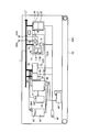
- FIG. 1 is a block diagram showing an overall configuration of a work vehicle equipped with an error canceling device for a work vehicle according to an embodiment of the present invention.
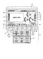
- FIG. 2 is a diagram showing an external configuration of the monitor.
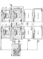
- FIG. 3 is a screen transition diagram of the display screen accompanying the operation procedure of the error cancellation processing.
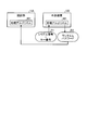
- FIG. 4 is an explanatory diagram illustrating generation of a one-time password by an external device.
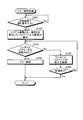
- FIG. 5 is a flowchart showing an outline of an error cancellation processing procedure by the error cancellation processing unit.
- FIG. 1 is a block diagram showing an overall configuration of a work vehicle equipped with an error canceling device for a work vehicle according to an embodiment of the present invention.
- the work vehicle 1 is, for example, a hydraulic excavator.
- the work vehicle 1 includes a processing device 10, a monitor 20, an engine controller 30, and a pump controller 50, and each is connected to an in-vehicle signal line L.
- the work vehicle 1 includes an engine 31, a hydraulic pump 32, an alternator 35, a rotation speed detection sensor 38, a fuel tank 41, an exhaust gas treatment device 40, a urea water tank 42, a capacitor 44, a key switch 46, and a starter 51.
- the engine controller 30 controls the engine 31 and the exhaust gas treatment device 40 that purifies the exhaust gas discharged from the engine 31.
- the engine 31 is a diesel engine.
- the exhaust gas treatment device 40 purifies the exhaust gas using urea SCR (Selective Catalytic Reduction), that is, urea water as a reducing agent. For this reason, urea water to be supplied to the exhaust gas treatment device 40 is stored in the urea water tank 42.
- the work vehicle 1 is equipped with an exhaust gas treatment system having the exhaust gas treatment device 40, the urea water tank 42, and the like.
- the engine controller 30 when the engine controller 30 detects an exhaust gas processing system-related error, the engine controller 30 performs derate control that is output limitation control of the engine 31.
- Exhaust gas treatment system-related errors include, for example, abnormalities in the sensor device such as abnormal transmission of data from the liquid level detection sensor 39A that detects the amount of urea water accumulated in the urea water tank 42 to the engine controller 30. This is an error related to the system. Error detection is performed by the engine controller 30.
- the derate control is to limit the output of the engine 31. For example, the output of the engine 31 may be limited to a low idle operation state, or the outputs of both the engine 31 and the hydraulic pump 32 may be limited. It may be.
- the engine controller 30 When the engine controller 30 performs engine output restriction control for the engine 31 or the like, the engine controller 30 displays that fact on the monitor 20. In addition, when there is an error cancellation instruction from an error cancellation processing unit 11B described later, the engine controller 30 cancels the engine output restriction control.
- the engine controller 30 controls the amount of fuel supplied to the engine 31 based on the rotational speed of the crankshaft of the engine 31 detected by the rotational speed detection sensor 38, the opening of the fuel adjustment dial 30S, and the like. That is, the engine controller 30 controls the operation of the engine 31.
- the engine controller 30 controls the amount of urea water supplied from the urea water tank 42 to the exhaust gas treatment device 40 based on the amount of nitrogen oxides contained in the exhaust gas discharged from the engine 31.
- the exhaust gas treatment device 40 includes a sensor that detects the amount of nitrogen oxide contained in the exhaust gas.
- the exhaust gas treatment device 40 is The urea water is supplied from the urea water tank 42 to an injection device (not shown), and the injection device injects the urea water into the exhaust gas. Nitrogen oxides contained in the exhaust gas are reduced to nitrogen and water by urea water.
- the engine controller 30 obtains the remaining amount of fuel in the fuel tank 41 based on the detection value of the liquid level detection sensor 39F that detects the amount of fuel stored in the fuel tank 41.
- the engine controller 30 transmits information indicating the obtained remaining fuel amount to the monitor 20, and displays the remaining fuel amount on a fuel gauge, for example.
- the engine controller 30 obtains the remaining amount of urea water in the urea water tank 42 based on the detection value of the liquid level detection sensor 39A that detects the amount of urea water stored in the urea water tank 42.
- the engine controller 30 transmits the obtained remaining amount of urea water to the monitor 20, for example, the monitor 20 displays the remaining amount of urea water on a urea water level gauge.
- the engine controller 30 transmits a “signal indicating that the engine 31 is in operation” to the monitor 20 via the in-vehicle signal line L, and the monitor 20 measures the time during which the signal is received and operates. Ask for time.
- the engine controller 30 receives a signal from the rotational speed detection sensor 38 that detects the rotational speed of the engine 31, generates a “signal indicating that the engine 31 is in operation” based on the signal, and monitors the monitor 20. Send to. Even if the “signal indicating that the engine 31 is in operation” is not transmitted from the engine controller 30 to the monitor 20 for some reason, the monitor 20 does not transmit the alternator signal from the alternator 35 to the monitor 20. Can measure the time during which the signal (predetermined voltage) is received from the alternator 35 to obtain the operating time.
- the traveling device 43 causes the work vehicle 1 to travel with the power generated by the engine 31.
- the traveling device 43 includes a hydraulic motor (not shown) and a crawler belt 43C.
- a hydraulic motor (not shown) in the traveling device 43 is rotated by hydraulic oil supplied from a hydraulic pump 32 driven by the engine 31.
- the work vehicle 1 travels when a hydraulic motor (not shown) rotates the crawler belt 43C.
- the swash plate angle of the hydraulic pump 32 is controlled by the pump controller 50, and the discharge amount of hydraulic oil supplied to a hydraulic cylinder of a working machine (not shown) is controlled.
- the Work vehicle 1 includes a capacitor 44.
- the battery 44 is, for example, a secondary battery such as a lead storage battery or a nickel hydride storage battery.
- the battery 44 supplies electric power to the starter 51 for starting the engine 31 and supplies electric power to various electronic devices included in the work vehicle 1 including the processing device 10.
- the battery 44 is charged with electric power supplied from the alternator 35.
- the alternator 35 generates electric power by being driven in conjunction with the driving of the engine 31.
- the electric power generated by the alternator 35 is charged in the battery 44.
- an alternator signal indicating that power is generated by the alternator 35 is transmitted to the monitor 20 via the signal line 35A.
- the monitor 20 can determine whether or not the alternator 35 is operating normally by receiving the alternator signal. As described above, instead of using the “signal indicating that the engine 31 is in operation”, the monitor 20 always counts the time during which the alternator signal is received, thereby operating the work vehicle 1. You may make it ask for time.
- the electric power supplied from the battery 44 is supplied to electronic devices such as the starter 51, the pump controller 50, the engine controller 30, the processing device 10, and the monitor 20 via the key switch 46.
- the key switch 46 is electrically connected to the battery 44, and the key switch 46 is electrically connected to the pump controller 50, the engine controller 30, the processing device 10, and the monitor 20.
- As the key switch 46 a cylinder lock, a push button type, an immobilizer key using wireless communication, or the like can be used.
- the key switch 46 When the key switch 46 is turned on, power is supplied from the capacitor 44 to the pump controller 50, the engine controller 30, the processing device 10, and the monitor 20.
- the key switch 46 When the key switch 46 is turned off, the electric power supplied from the capacitor 44 to the pump controller 50, the engine controller 30, the processing device 10, and the monitor 20 is cut off.
- the processing device 10 includes a processing unit 11, a storage unit 12, and an input / output unit 13.
- the processing device 10 controls the work vehicle 1 and generates abnormality information or collects operation information.
- the processing device 10 transmits the generated abnormality information and operation information to the outside of the work vehicle 1 via the communication device 14 and the antenna 14A, for example.
- the operation information includes information obtained from various sensors such as a pressure sensor, a rotation speed detection sensor 38, a temperature sensor, and liquid level detection sensors 39A and 39F (not shown).
- the information obtained from the pressure sensor includes the oil pressure of engine oil.
- the information obtained from the rotation speed detection sensor 38 includes the rotation speed of the engine 31, and the information obtained from the temperature sensor includes the temperature of the cooling water of the engine 31.
- the operation information also includes the position information of the work vehicle 1 detected by the position detection device 15 and the information related to the abnormality occurring in the work vehicle 1.
- the information regarding the abnormality that has occurred in the work vehicle 1 is, for example, a certain type of error code, the type of abnormality, or the occurrence time of the abnormality.
- the operation information is not limited to information related to an abnormality that has occurred in the work vehicle 1, and may include information indicating that the work vehicle 1 is operating normally, such as an operation time.
- the operation information may include an exhaust gas treatment system related error.
- the processing unit 11 generates operation information.
- the processing unit 11 includes an authentication unit 11A and an error cancellation processing unit 11B.
- temporary input information such as a one-time password for canceling an exhaust gas treatment system-related error is input from the monitor 20
- the authentication unit 11A authenticates this temporary input information.
- the error cancellation processing unit 11B performs processing for canceling the exhaust gas processing system-related error to be canceled and canceling the output restriction control by the engine controller 30.
- the input / output unit 13 is an interface that electrically connects the inside of the processing apparatus 10 and the in-vehicle signal line L.
- the in-vehicle signal line L is, for example, a CAN (Controller Area Network).
- a terminal LT is electrically connected to the in-vehicle signal line L.
- the communication device 14 includes an antenna 14A.
- the communication device 14 is used when the processing device 10 communicates with the outside of the work vehicle 1.
- the position detection device 15 includes a GPS antenna 15A.
- the position detection device 15 converts the radio wave received by the GPS antenna 15 ⁇ / b> A into an electric signal, and obtains the position information of the work vehicle 1.
- the monitor 20 is a display device that includes a display unit 21 that displays various types of information on the work vehicle 1 and an input unit 22 that inputs various types of information.
- the input unit 22 includes a plurality of switches.
- function switches F1 to F6 which are located below the display unit 21 and are displayed as “F1” to “F6”, correspond to the icons displayed on the display unit 21 above each switch. This is a switch for inputting a signal.
- an auto decel switch 211 for executing auto decel control for reducing the engine speed to a predetermined speed, and a plurality of work modes of the work vehicle 1 are provided.
- a work mode selection switch 212 for selecting from among the work modes, a travel speed stage selection switch 213 for selecting a travel speed stage of the work vehicle 1 from a plurality of travel speed stages, and a buzzer sound generated when the work vehicle 1 enters a predetermined warning state.
- the buzzer cancel switch 214 for canceling, the wiper switch 215 for operating the wiper provided on the windshield of the cab, the washer switch 216 for operating the washer for injecting cleaning water to the windshield, and various functions of the air conditioner in the cab are operated.
- Air conditioner switch 217 is provided There. Note that a resistive film type touch panel or the like can be applied as the input unit 22. In addition, among the switches of the input unit 22, the switch whose number is written on the right side also functions as a numeric keypad.
- the input unit 22 may be separate from the monitor 20.
- the input unit 22 may be provided on a console in a driver's cab (not shown).
- the screen displayed on the display unit 21 shown in FIG. 2 is the initial standard screen V0 when the key switch 46 is keyed on.
- the right hand side is set to the right and the left hand side is set to the left.
- a video display area M1 is provided in the left area of the initial standard screen V0. In this video display area M1, video captured by the camera is displayed.
- the camera is, for example, a camera installed on an upper portion of a counterweight (not shown) in order to photograph a rear view of the work vehicle 1.
- an engine water temperature gauge G1 indicating the temperature of the engine cooling water
- a hydraulic oil temperature gauge G2 indicating the temperature of the hydraulic oil in the hydraulic circuit
- the remaining fuel level are displayed.
- a fuel level gauge G3 is displayed in a triangular shape. The needles of the gauges G1 to G3 are swung based on the detection signals of the corresponding sensors.
- the hydraulic oil temperature gauge G2 may not be displayed on the initial standard screen V0. Further, the level gauges G1, G2, and G3 may be displayed side by side vertically or horizontally instead of being arranged in a triangular shape.
- a urea water level gauge G4 is displayed that indicates the level of the remaining amount of urea water in the urea water tank 42 in a bar shape.
- a fuel consumption gauge G5 that displays an average fuel consumption for a predetermined time and an instantaneous fuel consumption in a bar shape is displayed.
- guidance icons corresponding to the function switches F1 to F6 are displayed as necessary at positions below the initial standard screen V0 and above the function switches F1 to F6.
- guidance icons I3, I4 and I6 corresponding to the function switches F3, F4 and F6 are displayed.
- the guidance icon I6 is an icon that means switching to a user mode screen (not shown) for performing settings such as brightness adjustment and time adjustment of the screen displayed on the display unit 21.
- the user mode screen is displayed by pressing the function switch F6 while the initial standard screen V0 is displayed.
- the user mode screen is a user menu display screen that is set by a general user (an operator who operates the vehicle).
- an operation known to the specific person can make a transition to a service menu display screen that is set by the specific person.
- the “specific person” mentioned here is, for example, a manager of a work vehicle rental company or a service person of a work vehicle dealer. Or a person who has been given authority to cancel errors related to the exhaust gas treatment system.
- the input unit 22 is used to input a password that is not known to a general user and execute a special operation (for example, simultaneously pressing any one of the switches of the input unit 22). Is called. In this way, it is desirable to set so that a general user cannot transition to the service menu display screen.
- a service person displays the initial standard screen V0 shown in FIG. Enter unknown passwords and perform special operations.
- the display unit 21 displays the inspection screen V1 shown in FIG. With the inspection screen V1 displayed, the operator selects an item using the up / down movement icons using the function switches F3 and F4, presses the function switch F6 and confirms with the determination icon I1, and the selection is made.
- a display screen (not shown) corresponding to the item is displayed.
- the password input screen V2 is displayed. It is displayed on the display unit 21.
- the hidden information is information that is not displayed on the inspection screen V1.
- This hidden number is, for example, “90” and can be input by operating a switch that can also function as a numeric keypad as described above.
- This password input screen V2 is one of service menu display screens.
- a serial number D14 and a key number D15 are displayed.
- the serial number D14 and the key number D15 are inquiry information D1 necessary for acquiring a later-described one-time password D2 as temporary input information from the external device 100 shown in FIG.
- the serial number D14 is, for example, 6 digits.
- the serial number D14 may be a manufacturing number of the monitor 20, but a specific number may be determined in advance and the specific number may be used.
- the value of the key number D15 is incremented each time the one-time password D2 is authenticated by the authenticating unit 11A (hereinafter appropriately password authenticated) and displayed on the display unit 21.
- the key number D15 is a key number specific to an exhaust gas treatment system-related error, and is independent of key numbers used for other errors.
- title information D11, password input area information D12, and password input request information D13 are displayed on the password input screen V2.
- a determination icon I1 and a return icon I3 are displayed on the password input screen V2.
- the authentication unit 11A authenticates the password, and the screen transitions to the confirmation screen V4.
- the confirmation screen V4 On the confirmation screen V4, a confirmation message for confirming whether or not to cancel the exhaust gas treatment system related error is displayed.
- the error cancellation processing unit 11B instructs the engine controller 30 to cancel the exhaust gas processing system related error.
- the screen changes from the confirmation screen V4 to the release instruction in-progress screen V5 in which the determination icon I1 and the return icon I3 are deleted.
- a normal completion screen V6 is displayed.
- the selection icon I1 is selected to return to the inspection screen V1.
- the cancellation of the exhaust gas treatment system related error is described as “engine controller use restriction failure clear”.
- the operator selects the return icon I3 on the confirmation screen V4 or the like and transitions to the inspection screen V1, and then again by inputting the hidden number and selecting the decision icon I1 on the inspection screen V1 again. If it is going to change to password input screen V2, it changes not to password input screen V2 but to password input screen V3.
- password remaining validity period information D10 and a skip icon I2 are further displayed.
- an incremented value is displayed for the key number D15.
- the fact that the password remaining validity period information D10 and the skip icon I2 are displayed on the password input screen V3 means that password authentication has been performed once in the past, and the skip icon I2 within the password expiration date.
- the function switch F1 corresponding to is pressed, re-input of the one-time password D2 can be skipped. That is, since the password has been authenticated once within the password expiration date, only the skip icon I2 is selected, and the screen transitions to the confirmation screen V4.
- password authentication processing can be performed by inputting a new one-time password D2 and selecting the decision icon I1 without selecting the skip icon I2.
- an incremented key number D15 is displayed on the password input screen V3, and the operator can obtain a new one obtained from the external device 100 using the serial number D14 and the incremented key number D15 as inquiry information D1. You need to enter your time password.
- the normal one-time password D2 is, for example, a password generated by the external device 100 including the processing algorithm 101.
- the abnormal one-time password D2 is a password that is not generated by the external device 100 including the processing algorithm 101, for example.
- the password validity period is, for example, 8 hours, and as shown in FIG. 3, the remaining time (“7:59” in the example of FIG. 3) and the password are used as the remaining password validity period information D10.
- the effective period (“8:00” in the example of FIG. 3) is displayed on the display unit 21.
- the password input screen V3 displays the remaining password validity period information D10 as described above when the password is authenticated. Thereafter, the expiration of the password validity period is measured, and the remaining time is counted down and displayed.
- the display unit 21 automatically returns to the password entry screen V2 after the password validity period has elapsed.
- the password remaining validity period information D10 and the skip icon I2 disappear from the display screen. Note that the incremented key number D15 displayed on the password input screen V3 is displayed with its value maintained.
- the password validity period is determined because the one-time password D2 shown in the present embodiment is acquired from the external device 100 side and password authentication is performed. This is because when the operation is not performed immediately, the error related to the exhaust gas treatment system can be canceled without acquiring a new one-time password D2 from the external device 100 side again. Therefore, as described above, on the password input screen V3, the remaining password effective period information D10 and the skip icon I2 are displayed within the password effective period.
- the display unit 21 transitions to a password re-input screen V9 similar to the password re-input screen V8.
- the remaining password validity period information D10 is maintained and displayed, and a skip icon I2 is also displayed.
- the function switch F1 corresponding to the skip icon I2 is pressed to select one.
- the re-input of the time password D2 can be skipped.
- password re-input request information D20 is displayed on the password re-input screen V9, and the serial number D14, the key number D15, and the like are displayed in the same display form as the password re-input screen V8.
- the screen changes to the confirmation screen V4.
- the serial number D14 and the key number D15 displayed on the password re-input screen V9 are used as inquiry information D1, and the one-time password D2 acquired by the operator, that is, a normal new one-time password D2
- the screen transitions to the confirmation screen V4.
- the operator selects the return icon I3 on the password re-input screen V9, the screen transitions to the inspection screen V1.
- the password used in the present embodiment is not a fixed password but the above-mentioned one-time password D2.
- the one-time password D2 is a disposable password that can be used only once, and has, for example, 10 digits. By using this one-time password D2, the security level of error cancellation processing can be improved.
- the one-time password D ⁇ b> 2 can be acquired by inquiring a manager or the like of the external device 100 by telephone or the like.
- the one-time password D2 can be acquired by notifying the serial number D14 and the key number D15 displayed on the password input screen V2 or the like as inquiry information D1.
- the external device 100 has a processing algorithm 101 for generating a one-time password D2.
- the authentication unit 11 ⁇ / b> A provided in the processing device 10 of the work vehicle 1 has a processing algorithm 101 that is common to the processing algorithm 101.
- the common processing algorithm 101 may be realized by software or a specific function, for example. Since the processing algorithm 101 on the authentication unit 11A side acquires the serial number D14 and the key number D15 from the monitor 20, it generates the same one-time password D2 as the one-time password D2 acquired from the external device 100. become. As a result, the authentication unit 11A includes the one-time password D2 generated by the processing algorithm 101 on the authentication unit 11A side and the one-time password D2 acquired by the external device 100, which is input to the authentication unit 11A via the input unit 22. Password authentication can be performed simply by comparing the passwords.
- the error cancellation processing unit 11B determines whether or not a hidden number has been input on the inspection screen V1 (step S101). If the hidden number is not input (No at Step S101), the determination process at Step S101 is repeated. On the other hand, when the hidden number is input (step S101, Yes), the serial number D14 and the key number D15 are displayed on the password input screen V2 (step S102). Here, the operator notifies the external device 100 of the serial number D14 and the key number D15 to obtain the one-time password D2, and inputs the one-time password D2.
- the error cancellation processing unit 11B determines whether or not the input one-time password D2 has been authenticated by the authentication unit 11A (step S103). If the one-time password D2 is authenticated (step S103, Yes), the engine controller 30 is released from the exhaust gas treatment system related error (step S106), and the process is terminated. On the other hand, if the one-time password D2 is not authenticated (step S103, No), the password re-input screen V8 is displayed to request re-input of the one-time password D2 (step S104). Thereafter, it is determined whether or not there is an instruction to end the process (step S105). If there is an instruction to end the process (step S105, Yes), the process ends and there is no instruction to end the process. In the case (No at Step S105), the process proceeds to Step S103, and the above-described processing is repeated.
- the temporary input information described above is the one-time password D2, but may be information indicating a special operation on the input unit 22 instead. For example, it may be information indicating a special operation in which the auto-decel switch 211 and the work mode selection switch 212 of the input unit 22 are pressed simultaneously. Information indicating this special operation can have the same function as the one-time password D2.
- the temporary input information described above was the one-time password D2, but instead of this, a predetermined password is stored in the authentication unit 11A and the external device 100, and the exhaust gas is exhausted using this password. The processing system related error may be canceled. In this case, when a specific person inquires the external device 100 to acquire the password and inputs the acquired password to the input unit 22, the authentication unit 11A obtains the password stored by itself and the input password. What is necessary is just to authenticate in comparison.
- the authentication unit 11A and the error cancellation processing unit 11B may be provided in the monitor 20 and the engine controller 30 connected to the in-vehicle signal line L in addition to the processing device 10.
- the work vehicle 1 including the error canceling device for the exhaust gas treatment system related error has been described.
- work vehicle 1 may also be provided with an error canceling device different from the error canceling device shown in the present embodiment in order to cancel other errors.
Priority Applications (7)
| Application Number | Priority Date | Filing Date | Title |
|---|---|---|---|
| DE112014000046.9T DE112014000046B4 (de) | 2014-02-28 | 2014-02-28 | Fehleraufhebungsvorrichtung für ein Arbeitsfahrzeug und Fehleraufhebungsverfahren für ein Arbeitsfahrzeug |
| KR1020157005819A KR101700423B1 (ko) | 2014-02-28 | 2014-02-28 | 작업 차량의 에러 해제 장치 및 작업 차량의 에러 해제 방법 |
| JP2014517300A JP5876572B2 (ja) | 2014-02-28 | 2014-02-28 | 作業車両のエラー解除装置及び作業車両のエラー解除方法 |
| PCT/JP2014/055189 WO2015025542A1 (ja) | 2014-02-28 | 2014-02-28 | 作業車両のエラー解除装置及び作業車両のエラー解除方法 |
| CN201480000636.4A CN105025999B (zh) | 2014-02-28 | 2014-02-28 | 作业车辆的错误解除装置以及作业车辆的错误解除方法 |
| IN1882DEN2015 IN2015DN01882A (de) | 2014-02-28 | 2014-02-28 | |
| US14/370,648 US9353669B2 (en) | 2014-02-28 | 2014-02-28 | Error releasing device for work vehicle and error releasing method for work vehicle |
Applications Claiming Priority (1)
| Application Number | Priority Date | Filing Date | Title |
|---|---|---|---|
| PCT/JP2014/055189 WO2015025542A1 (ja) | 2014-02-28 | 2014-02-28 | 作業車両のエラー解除装置及び作業車両のエラー解除方法 |
Publications (1)
| Publication Number | Publication Date |
|---|---|
| WO2015025542A1 true WO2015025542A1 (ja) | 2015-02-26 |
Family
ID=52483333
Family Applications (1)
| Application Number | Title | Priority Date | Filing Date |
|---|---|---|---|
| PCT/JP2014/055189 WO2015025542A1 (ja) | 2014-02-28 | 2014-02-28 | 作業車両のエラー解除装置及び作業車両のエラー解除方法 |
Country Status (7)
| Country | Link |
|---|---|
| US (1) | US9353669B2 (de) |
| JP (1) | JP5876572B2 (de) |
| KR (1) | KR101700423B1 (de) |
| CN (1) | CN105025999B (de) |
| DE (1) | DE112014000046B4 (de) |
| IN (1) | IN2015DN01882A (de) |
| WO (1) | WO2015025542A1 (de) |
Cited By (4)
| Publication number | Priority date | Publication date | Assignee | Title |
|---|---|---|---|---|
| WO2016043347A1 (ja) * | 2015-10-05 | 2016-03-24 | 株式会社小松製作所 | 作業車両及び作業車両の制御方法 |
| JP2017104084A (ja) * | 2015-12-11 | 2017-06-15 | ヤンマー株式会社 | コンバイン |
| JP2019144720A (ja) * | 2018-02-19 | 2019-08-29 | 沖電気工業株式会社 | 情報処理システム及び情報処理装置 |
| WO2023106046A1 (ja) * | 2021-12-09 | 2023-06-15 | 株式会社小松製作所 | 車両監視装置、および車両監視方法 |
Families Citing this family (4)
| Publication number | Priority date | Publication date | Assignee | Title |
|---|---|---|---|---|
| CN104797463B (zh) * | 2013-11-19 | 2017-03-15 | 株式会社小松制作所 | 作业车辆的显示装置及其显示方法 |
| JP6363668B2 (ja) * | 2016-08-31 | 2018-07-25 | 本田技研工業株式会社 | 車両用表示装置 |
| US10902148B2 (en) * | 2017-12-07 | 2021-01-26 | Verizon Media Inc. | Securing digital content using separately authenticated hidden folders |
| USD989717S1 (en) * | 2021-06-14 | 2023-06-20 | Buzzztv Ltd | Display screen |
Citations (6)
| Publication number | Priority date | Publication date | Assignee | Title |
|---|---|---|---|---|
| JP2008102840A (ja) * | 2006-10-20 | 2008-05-01 | Ricoh Co Ltd | ソフトウェア実行制御プログラム及びソフトウェア実行制御方法 |
| JP2009053776A (ja) * | 2007-08-24 | 2009-03-12 | Kubota Corp | 自動販売機 |
| JP2009243167A (ja) * | 2008-03-31 | 2009-10-22 | Komatsu Ltd | 建設機械の表示制御装置 |
| WO2011074672A1 (ja) * | 2009-12-18 | 2011-06-23 | 株式会社小松製作所 | 作業車両のモニタ装置 |
| JP2012027530A (ja) * | 2010-07-20 | 2012-02-09 | Dainippon Printing Co Ltd | ワンタイムパスワード生成装置、サーバー装置、認証システム、方法、プログラム、記録媒体 |
| JP2013227969A (ja) * | 2012-03-30 | 2013-11-07 | Kubota Corp | ディーゼルエンジンの排気処理装置 |
Family Cites Families (19)
| Publication number | Priority date | Publication date | Assignee | Title |
|---|---|---|---|---|
| US6275231B1 (en) | 1997-08-01 | 2001-08-14 | American Calcar Inc. | Centralized control and management system for automobiles |
| JP2000073842A (ja) | 1998-09-01 | 2000-03-07 | Nissan Motor Co Ltd | 車両の故障時警報装置 |
| JP3680650B2 (ja) * | 1999-01-25 | 2005-08-10 | トヨタ自動車株式会社 | 内燃機関の排気浄化装置 |
| KR100312565B1 (ko) | 1999-09-16 | 2001-11-09 | 이계안 | 차량의 키레스엔트리방법 |
| JP4477207B2 (ja) | 2000-08-31 | 2010-06-09 | 株式会社小松製作所 | 建設機械の機能ロック解除装置 |
| US7194369B2 (en) * | 2001-07-23 | 2007-03-20 | Cognis Corporation | On-site analysis system with central processor and method of analyzing |
| JP2003193903A (ja) * | 2001-12-25 | 2003-07-09 | Mitsubishi Motors Corp | 空燃比検出手段の故障判定装置 |
| JP4350931B2 (ja) * | 2002-02-12 | 2009-10-28 | 株式会社デンソー | 車両の異常診断装置及び異常診断方法 |
| US7278024B2 (en) * | 2003-07-16 | 2007-10-02 | Intel Corporation | Session authentication using temporary passwords |
| US8316636B2 (en) * | 2006-06-01 | 2012-11-27 | Hitachi Construction Machinery Co., Ltd. | Exhaust gas purifier of construction machine |
| DE102006029990A1 (de) * | 2006-06-29 | 2008-01-03 | Robert Bosch Gmbh | Verfahren zur Diagnose eines Partikelfilters und Vorrichtung zur Durchführung des Verfahrens |
| JP4325691B2 (ja) | 2007-03-22 | 2009-09-02 | 株式会社デンソー | 車両制御装置のためのメモリ読み出しシステム |
| JP4852024B2 (ja) | 2007-11-22 | 2012-01-11 | 日立建機株式会社 | 作業車両の排ガス後処理装置 |
| EP2335176A1 (de) * | 2008-08-20 | 2011-06-22 | Wherepro, LLC | Datenpaketgenerator zur erzeugung von passcodes |
| JP4774096B2 (ja) * | 2008-11-17 | 2011-09-14 | 日立建機株式会社 | 作業機械の排気ガス浄化システム |
| JP5658075B2 (ja) * | 2011-04-15 | 2015-01-21 | 日立建機株式会社 | 作業機の排気浄化システム |
| US8775008B2 (en) * | 2011-12-14 | 2014-07-08 | GTR Development LLC | Electrical system health monitor (ESHM) system and method |
| US9222389B2 (en) * | 2012-02-02 | 2015-12-29 | Cummins Inc. | Systems and methods for controlling reductant delivery to an exhaust stream |
| CN104508262B (zh) | 2012-06-07 | 2018-08-07 | 康明斯有限公司 | Scr后处理系统维护诱导方法 |
-
2014
- 2014-02-28 CN CN201480000636.4A patent/CN105025999B/zh active Active
- 2014-02-28 JP JP2014517300A patent/JP5876572B2/ja active Active
- 2014-02-28 DE DE112014000046.9T patent/DE112014000046B4/de active Active
- 2014-02-28 US US14/370,648 patent/US9353669B2/en active Active
- 2014-02-28 WO PCT/JP2014/055189 patent/WO2015025542A1/ja active Application Filing
- 2014-02-28 KR KR1020157005819A patent/KR101700423B1/ko active IP Right Grant
- 2014-02-28 IN IN1882DEN2015 patent/IN2015DN01882A/en unknown
Patent Citations (6)
| Publication number | Priority date | Publication date | Assignee | Title |
|---|---|---|---|---|
| JP2008102840A (ja) * | 2006-10-20 | 2008-05-01 | Ricoh Co Ltd | ソフトウェア実行制御プログラム及びソフトウェア実行制御方法 |
| JP2009053776A (ja) * | 2007-08-24 | 2009-03-12 | Kubota Corp | 自動販売機 |
| JP2009243167A (ja) * | 2008-03-31 | 2009-10-22 | Komatsu Ltd | 建設機械の表示制御装置 |
| WO2011074672A1 (ja) * | 2009-12-18 | 2011-06-23 | 株式会社小松製作所 | 作業車両のモニタ装置 |
| JP2012027530A (ja) * | 2010-07-20 | 2012-02-09 | Dainippon Printing Co Ltd | ワンタイムパスワード生成装置、サーバー装置、認証システム、方法、プログラム、記録媒体 |
| JP2013227969A (ja) * | 2012-03-30 | 2013-11-07 | Kubota Corp | ディーゼルエンジンの排気処理装置 |
Cited By (6)
| Publication number | Priority date | Publication date | Assignee | Title |
|---|---|---|---|---|
| WO2016043347A1 (ja) * | 2015-10-05 | 2016-03-24 | 株式会社小松製作所 | 作業車両及び作業車両の制御方法 |
| JP5976958B1 (ja) * | 2015-10-05 | 2016-08-24 | 株式会社小松製作所 | 作業車両及び作業車両の制御方法 |
| US9677250B2 (en) | 2015-10-05 | 2017-06-13 | Komatsu Ltd. | Work vehicle and method of controlling work vehicle |
| JP2017104084A (ja) * | 2015-12-11 | 2017-06-15 | ヤンマー株式会社 | コンバイン |
| JP2019144720A (ja) * | 2018-02-19 | 2019-08-29 | 沖電気工業株式会社 | 情報処理システム及び情報処理装置 |
| WO2023106046A1 (ja) * | 2021-12-09 | 2023-06-15 | 株式会社小松製作所 | 車両監視装置、および車両監視方法 |
Also Published As
| Publication number | Publication date |
|---|---|
| CN105025999A (zh) | 2015-11-04 |
| JPWO2015025542A1 (ja) | 2017-03-02 |
| DE112014000046B4 (de) | 2022-01-05 |
| KR20150102930A (ko) | 2015-09-09 |
| US20150300232A1 (en) | 2015-10-22 |
| IN2015DN01882A (de) | 2015-07-03 |
| KR101700423B1 (ko) | 2017-01-26 |
| US9353669B2 (en) | 2016-05-31 |
| JP5876572B2 (ja) | 2016-03-02 |
| CN105025999B (zh) | 2018-05-04 |
| DE112014000046T5 (de) | 2015-06-18 |
Similar Documents
| Publication | Publication Date | Title |
|---|---|---|
| JP5876572B2 (ja) | 作業車両のエラー解除装置及び作業車両のエラー解除方法 | |
| JP5807116B2 (ja) | 作業車両及び作業車両用表示装置 | |
| JP5419496B2 (ja) | 異常検知および車両追跡装置 | |
| KR102178352B1 (ko) | 차량 도어록 시정 및 해정용 차재기기, 이 차재기기를 구비한 차량, 이 차재기기를 구비한 차량 도어록 시정 및 해정용 시스템 | |
| JP6238038B1 (ja) | 車両遠隔制御システム | |
| US20220080923A1 (en) | Method and a system for controlling and monitoring operation of a device | |
| JP5798683B2 (ja) | 作業車両の尿素水補給ガイダンス出力装置および作業車両の尿素水補給ガイダンス出力方法 | |
| US20160265196A1 (en) | Display device of working vehicle, display method of the same, and working vehicle | |
| JP5876571B2 (ja) | 作業車両用表示装置及び作業車両 | |
| KR101691317B1 (ko) | 작업 차량의 표시 장치 및 그 표시 방법 | |
| WO2015040762A1 (ja) | 作業機械、作業機械の管理システム及び作業機械の管理方法 | |
| JP5173550B2 (ja) | 車載用電子キーシステム | |
| CN104340175A (zh) | 车辆控制装置和车辆控制方法 | |
| JP5664579B2 (ja) | 通信システム、中継装置、車外装置及び通信方法 | |
| JP3692593B2 (ja) | 車両盗難防止装置 | |
| JP5765638B2 (ja) | 操作忘れ通知方法、及び操作忘れ通知システム | |
| JP2021187426A (ja) | システム、システム制御方法、システム制御プログラム及び記憶媒体 | |
| KR101669668B1 (ko) | 차량 가동 정보를 이용한 공회전 제한 장치 및 방법 | |
| JP2012211465A (ja) | 盗難防止装置 | |
| JP2014141803A (ja) | 車両の電子キーシステム | |
| WO2023243523A1 (ja) | 制御装置及び制御システム | |
| WO2023106135A1 (ja) | 車両制御装置、車両制御方法、制御プログラム | |
| JP2023181967A (ja) | 制御装置及び制御システム | |
| JP2017166412A (ja) | 電子制御装置 |
Legal Events
| Date | Code | Title | Description |
|---|---|---|---|
| WWE | Wipo information: entry into national phase |
Ref document number: 201480000636.4 Country of ref document: CN |
|
| ENP | Entry into the national phase |
Ref document number: 2014517300 Country of ref document: JP Kind code of ref document: A |
|
| WWE | Wipo information: entry into national phase |
Ref document number: 14370648 Country of ref document: US |
|
| WWE | Wipo information: entry into national phase |
Ref document number: 1120140000469 Country of ref document: DE Ref document number: 112014000046 Country of ref document: DE |
|
| ENP | Entry into the national phase |
Ref document number: 20157005819 Country of ref document: KR Kind code of ref document: A |
|
| 121 | Ep: the epo has been informed by wipo that ep was designated in this application |
Ref document number: 14838647 Country of ref document: EP Kind code of ref document: A1 |
|
| 122 | Ep: pct application non-entry in european phase |
Ref document number: 14838647 Country of ref document: EP Kind code of ref document: A1 |