WO2015025535A1 - 作業車両用表示装置及び作業車両 - Google Patents
作業車両用表示装置及び作業車両 Download PDFInfo
- Publication number
- WO2015025535A1 WO2015025535A1 PCT/JP2014/053785 JP2014053785W WO2015025535A1 WO 2015025535 A1 WO2015025535 A1 WO 2015025535A1 JP 2014053785 W JP2014053785 W JP 2014053785W WO 2015025535 A1 WO2015025535 A1 WO 2015025535A1
- Authority
- WO
- WIPO (PCT)
- Prior art keywords
- image
- urea water
- display
- work vehicle
- exhaust gas
- Prior art date
- Legal status (The legal status is an assumption and is not a legal conclusion. Google has not performed a legal analysis and makes no representation as to the accuracy of the status listed.)
- Ceased
Links
Images
Classifications
-
- F—MECHANICAL ENGINEERING; LIGHTING; HEATING; WEAPONS; BLASTING
- F01—MACHINES OR ENGINES IN GENERAL; ENGINE PLANTS IN GENERAL; STEAM ENGINES
- F01N—GAS-FLOW SILENCERS OR EXHAUST APPARATUS FOR MACHINES OR ENGINES IN GENERAL; GAS-FLOW SILENCERS OR EXHAUST APPARATUS FOR INTERNAL-COMBUSTION ENGINES
- F01N11/00—Monitoring or diagnostic devices for exhaust-gas treatment apparatus
-
- B—PERFORMING OPERATIONS; TRANSPORTING
- B60—VEHICLES IN GENERAL
- B60K—ARRANGEMENT OR MOUNTING OF PROPULSION UNITS OR OF TRANSMISSIONS IN VEHICLES; ARRANGEMENT OR MOUNTING OF PLURAL DIVERSE PRIME-MOVERS IN VEHICLES; AUXILIARY DRIVES FOR VEHICLES; INSTRUMENTATION OR DASHBOARDS FOR VEHICLES; ARRANGEMENTS IN CONNECTION WITH COOLING, AIR INTAKE, GAS EXHAUST OR FUEL SUPPLY OF PROPULSION UNITS IN VEHICLES
- B60K35/00—Instruments specially adapted for vehicles; Arrangement of instruments in or on vehicles
- B60K35/10—Input arrangements, i.e. from user to vehicle, associated with vehicle functions or specially adapted therefor
-
- B—PERFORMING OPERATIONS; TRANSPORTING
- B60—VEHICLES IN GENERAL
- B60K—ARRANGEMENT OR MOUNTING OF PROPULSION UNITS OR OF TRANSMISSIONS IN VEHICLES; ARRANGEMENT OR MOUNTING OF PLURAL DIVERSE PRIME-MOVERS IN VEHICLES; AUXILIARY DRIVES FOR VEHICLES; INSTRUMENTATION OR DASHBOARDS FOR VEHICLES; ARRANGEMENTS IN CONNECTION WITH COOLING, AIR INTAKE, GAS EXHAUST OR FUEL SUPPLY OF PROPULSION UNITS IN VEHICLES
- B60K35/00—Instruments specially adapted for vehicles; Arrangement of instruments in or on vehicles
- B60K35/20—Output arrangements, i.e. from vehicle to user, associated with vehicle functions or specially adapted therefor
- B60K35/21—Output arrangements, i.e. from vehicle to user, associated with vehicle functions or specially adapted therefor using visual output, e.g. blinking lights or matrix displays
- B60K35/213—Virtual instruments
-
- B—PERFORMING OPERATIONS; TRANSPORTING
- B60—VEHICLES IN GENERAL
- B60K—ARRANGEMENT OR MOUNTING OF PROPULSION UNITS OR OF TRANSMISSIONS IN VEHICLES; ARRANGEMENT OR MOUNTING OF PLURAL DIVERSE PRIME-MOVERS IN VEHICLES; AUXILIARY DRIVES FOR VEHICLES; INSTRUMENTATION OR DASHBOARDS FOR VEHICLES; ARRANGEMENTS IN CONNECTION WITH COOLING, AIR INTAKE, GAS EXHAUST OR FUEL SUPPLY OF PROPULSION UNITS IN VEHICLES
- B60K35/00—Instruments specially adapted for vehicles; Arrangement of instruments in or on vehicles
- B60K35/20—Output arrangements, i.e. from vehicle to user, associated with vehicle functions or specially adapted therefor
- B60K35/21—Output arrangements, i.e. from vehicle to user, associated with vehicle functions or specially adapted therefor using visual output, e.g. blinking lights or matrix displays
- B60K35/22—Display screens
-
- B—PERFORMING OPERATIONS; TRANSPORTING
- B60—VEHICLES IN GENERAL
- B60K—ARRANGEMENT OR MOUNTING OF PROPULSION UNITS OR OF TRANSMISSIONS IN VEHICLES; ARRANGEMENT OR MOUNTING OF PLURAL DIVERSE PRIME-MOVERS IN VEHICLES; AUXILIARY DRIVES FOR VEHICLES; INSTRUMENTATION OR DASHBOARDS FOR VEHICLES; ARRANGEMENTS IN CONNECTION WITH COOLING, AIR INTAKE, GAS EXHAUST OR FUEL SUPPLY OF PROPULSION UNITS IN VEHICLES
- B60K35/00—Instruments specially adapted for vehicles; Arrangement of instruments in or on vehicles
- B60K35/20—Output arrangements, i.e. from vehicle to user, associated with vehicle functions or specially adapted therefor
- B60K35/28—Output arrangements, i.e. from vehicle to user, associated with vehicle functions or specially adapted therefor characterised by the type of the output information, e.g. video entertainment or vehicle dynamics information; characterised by the purpose of the output information, e.g. for attracting the attention of the driver
-
- F—MECHANICAL ENGINEERING; LIGHTING; HEATING; WEAPONS; BLASTING
- F01—MACHINES OR ENGINES IN GENERAL; ENGINE PLANTS IN GENERAL; STEAM ENGINES
- F01N—GAS-FLOW SILENCERS OR EXHAUST APPARATUS FOR MACHINES OR ENGINES IN GENERAL; GAS-FLOW SILENCERS OR EXHAUST APPARATUS FOR INTERNAL-COMBUSTION ENGINES
- F01N3/00—Exhaust or silencing apparatus having means for purifying, rendering innocuous, or otherwise treating exhaust
- F01N3/08—Exhaust or silencing apparatus having means for purifying, rendering innocuous, or otherwise treating exhaust for rendering innocuous
- F01N3/10—Exhaust or silencing apparatus having means for purifying, rendering innocuous, or otherwise treating exhaust for rendering innocuous by thermal or catalytic conversion of noxious components of exhaust
- F01N3/18—Exhaust or silencing apparatus having means for purifying, rendering innocuous, or otherwise treating exhaust for rendering innocuous by thermal or catalytic conversion of noxious components of exhaust characterised by methods of operation; Control
-
- F—MECHANICAL ENGINEERING; LIGHTING; HEATING; WEAPONS; BLASTING
- F01—MACHINES OR ENGINES IN GENERAL; ENGINE PLANTS IN GENERAL; STEAM ENGINES
- F01N—GAS-FLOW SILENCERS OR EXHAUST APPARATUS FOR MACHINES OR ENGINES IN GENERAL; GAS-FLOW SILENCERS OR EXHAUST APPARATUS FOR INTERNAL-COMBUSTION ENGINES
- F01N3/00—Exhaust or silencing apparatus having means for purifying, rendering innocuous, or otherwise treating exhaust
- F01N3/08—Exhaust or silencing apparatus having means for purifying, rendering innocuous, or otherwise treating exhaust for rendering innocuous
- F01N3/10—Exhaust or silencing apparatus having means for purifying, rendering innocuous, or otherwise treating exhaust for rendering innocuous by thermal or catalytic conversion of noxious components of exhaust
- F01N3/18—Exhaust or silencing apparatus having means for purifying, rendering innocuous, or otherwise treating exhaust for rendering innocuous by thermal or catalytic conversion of noxious components of exhaust characterised by methods of operation; Control
- F01N3/20—Exhaust or silencing apparatus having means for purifying, rendering innocuous, or otherwise treating exhaust for rendering innocuous by thermal or catalytic conversion of noxious components of exhaust characterised by methods of operation; Control specially adapted for catalytic conversion
- F01N3/206—Adding periodically or continuously substances to exhaust gases for promoting purification, e.g. catalytic material in liquid form, NOx reducing agents
- F01N3/2066—Selective catalytic reduction [SCR]
-
- B—PERFORMING OPERATIONS; TRANSPORTING
- B60—VEHICLES IN GENERAL
- B60K—ARRANGEMENT OR MOUNTING OF PROPULSION UNITS OR OF TRANSMISSIONS IN VEHICLES; ARRANGEMENT OR MOUNTING OF PLURAL DIVERSE PRIME-MOVERS IN VEHICLES; AUXILIARY DRIVES FOR VEHICLES; INSTRUMENTATION OR DASHBOARDS FOR VEHICLES; ARRANGEMENTS IN CONNECTION WITH COOLING, AIR INTAKE, GAS EXHAUST OR FUEL SUPPLY OF PROPULSION UNITS IN VEHICLES
- B60K2360/00—Indexing scheme associated with groups B60K35/00 or B60K37/00 relating to details of instruments or dashboards
- B60K2360/16—Type of output information
- B60K2360/168—Target or limit values
-
- B—PERFORMING OPERATIONS; TRANSPORTING
- B60—VEHICLES IN GENERAL
- B60K—ARRANGEMENT OR MOUNTING OF PROPULSION UNITS OR OF TRANSMISSIONS IN VEHICLES; ARRANGEMENT OR MOUNTING OF PLURAL DIVERSE PRIME-MOVERS IN VEHICLES; AUXILIARY DRIVES FOR VEHICLES; INSTRUMENTATION OR DASHBOARDS FOR VEHICLES; ARRANGEMENTS IN CONNECTION WITH COOLING, AIR INTAKE, GAS EXHAUST OR FUEL SUPPLY OF PROPULSION UNITS IN VEHICLES
- B60K2360/00—Indexing scheme associated with groups B60K35/00 or B60K37/00 relating to details of instruments or dashboards
- B60K2360/60—Structural details of dashboards or instruments
- B60K2360/61—Specially adapted for utility vehicles
-
- E—FIXED CONSTRUCTIONS
- E02—HYDRAULIC ENGINEERING; FOUNDATIONS; SOIL SHIFTING
- E02F—DREDGING; SOIL-SHIFTING
- E02F9/00—Component parts of dredgers or soil-shifting machines, not restricted to one of the kinds covered by groups E02F3/00 - E02F7/00
- E02F9/08—Superstructures; Supports for superstructures
- E02F9/0858—Arrangement of component parts installed on superstructures not otherwise provided for, e.g. electric components, fenders, air-conditioning units
- E02F9/0883—Tanks, e.g. oil tank, urea tank, fuel tank
-
- E—FIXED CONSTRUCTIONS
- E02—HYDRAULIC ENGINEERING; FOUNDATIONS; SOIL SHIFTING
- E02F—DREDGING; SOIL-SHIFTING
- E02F9/00—Component parts of dredgers or soil-shifting machines, not restricted to one of the kinds covered by groups E02F3/00 - E02F7/00
- E02F9/20—Drives; Control devices
- E02F9/2025—Particular purposes of control systems not otherwise provided for
- E02F9/2045—Guiding machines along a predetermined path
-
- E—FIXED CONSTRUCTIONS
- E02—HYDRAULIC ENGINEERING; FOUNDATIONS; SOIL SHIFTING
- E02F—DREDGING; SOIL-SHIFTING
- E02F9/00—Component parts of dredgers or soil-shifting machines, not restricted to one of the kinds covered by groups E02F3/00 - E02F7/00
- E02F9/26—Indicating devices
- E02F9/267—Diagnosing or detecting failure of vehicles
-
- F—MECHANICAL ENGINEERING; LIGHTING; HEATING; WEAPONS; BLASTING
- F01—MACHINES OR ENGINES IN GENERAL; ENGINE PLANTS IN GENERAL; STEAM ENGINES
- F01N—GAS-FLOW SILENCERS OR EXHAUST APPARATUS FOR MACHINES OR ENGINES IN GENERAL; GAS-FLOW SILENCERS OR EXHAUST APPARATUS FOR INTERNAL-COMBUSTION ENGINES
- F01N2550/00—Monitoring or diagnosing the deterioration of exhaust systems
- F01N2550/05—Systems for adding substances into exhaust
-
- F—MECHANICAL ENGINEERING; LIGHTING; HEATING; WEAPONS; BLASTING
- F01—MACHINES OR ENGINES IN GENERAL; ENGINE PLANTS IN GENERAL; STEAM ENGINES
- F01N—GAS-FLOW SILENCERS OR EXHAUST APPARATUS FOR MACHINES OR ENGINES IN GENERAL; GAS-FLOW SILENCERS OR EXHAUST APPARATUS FOR INTERNAL-COMBUSTION ENGINES
- F01N2590/00—Exhaust or silencing apparatus adapted to particular use, e.g. for military applications, airplanes, submarines
- F01N2590/08—Exhaust or silencing apparatus adapted to particular use, e.g. for military applications, airplanes, submarines for heavy duty applications, e.g. trucks, buses, tractors, locomotives
-
- F—MECHANICAL ENGINEERING; LIGHTING; HEATING; WEAPONS; BLASTING
- F01—MACHINES OR ENGINES IN GENERAL; ENGINE PLANTS IN GENERAL; STEAM ENGINES
- F01N—GAS-FLOW SILENCERS OR EXHAUST APPARATUS FOR MACHINES OR ENGINES IN GENERAL; GAS-FLOW SILENCERS OR EXHAUST APPARATUS FOR INTERNAL-COMBUSTION ENGINES
- F01N2900/00—Details of electrical control or of the monitoring of the exhaust gas treating apparatus
- F01N2900/06—Parameters used for exhaust control or diagnosing
- F01N2900/18—Parameters used for exhaust control or diagnosing said parameters being related to the system for adding a substance into the exhaust
- F01N2900/1806—Properties of reducing agent or dosing system
- F01N2900/1814—Tank level
-
- Y—GENERAL TAGGING OF NEW TECHNOLOGICAL DEVELOPMENTS; GENERAL TAGGING OF CROSS-SECTIONAL TECHNOLOGIES SPANNING OVER SEVERAL SECTIONS OF THE IPC; TECHNICAL SUBJECTS COVERED BY FORMER USPC CROSS-REFERENCE ART COLLECTIONS [XRACs] AND DIGESTS
- Y02—TECHNOLOGIES OR APPLICATIONS FOR MITIGATION OR ADAPTATION AGAINST CLIMATE CHANGE
- Y02A—TECHNOLOGIES FOR ADAPTATION TO CLIMATE CHANGE
- Y02A50/00—TECHNOLOGIES FOR ADAPTATION TO CLIMATE CHANGE in human health protection, e.g. against extreme weather
- Y02A50/20—Air quality improvement or preservation, e.g. vehicle emission control or emission reduction by using catalytic converters
-
- Y—GENERAL TAGGING OF NEW TECHNOLOGICAL DEVELOPMENTS; GENERAL TAGGING OF CROSS-SECTIONAL TECHNOLOGIES SPANNING OVER SEVERAL SECTIONS OF THE IPC; TECHNICAL SUBJECTS COVERED BY FORMER USPC CROSS-REFERENCE ART COLLECTIONS [XRACs] AND DIGESTS
- Y02—TECHNOLOGIES OR APPLICATIONS FOR MITIGATION OR ADAPTATION AGAINST CLIMATE CHANGE
- Y02T—CLIMATE CHANGE MITIGATION TECHNOLOGIES RELATED TO TRANSPORTATION
- Y02T10/00—Road transport of goods or passengers
- Y02T10/10—Internal combustion engine [ICE] based vehicles
- Y02T10/12—Improving ICE efficiencies
-
- Y—GENERAL TAGGING OF NEW TECHNOLOGICAL DEVELOPMENTS; GENERAL TAGGING OF CROSS-SECTIONAL TECHNOLOGIES SPANNING OVER SEVERAL SECTIONS OF THE IPC; TECHNICAL SUBJECTS COVERED BY FORMER USPC CROSS-REFERENCE ART COLLECTIONS [XRACs] AND DIGESTS
- Y02—TECHNOLOGIES OR APPLICATIONS FOR MITIGATION OR ADAPTATION AGAINST CLIMATE CHANGE
- Y02T—CLIMATE CHANGE MITIGATION TECHNOLOGIES RELATED TO TRANSPORTATION
- Y02T10/00—Road transport of goods or passengers
- Y02T10/10—Internal combustion engine [ICE] based vehicles
- Y02T10/40—Engine management systems
Definitions
- the present invention relates to a display device for a work vehicle that is provided in the work vehicle and displays various types of information, and a work vehicle including the display device for the work vehicle.
- Some work vehicles such as hydraulic excavators and dump trucks have an internal combustion engine such as a diesel engine as a power generation source. From the viewpoint of reducing the environmental load, it is required to exhaust the exhaust gas exhausted by the internal combustion engine before exhausting it. For this reason, some work vehicles include a device for purifying exhaust gas (for example, Patent Document 1).
- Some work vehicles equipped with a device that purifies exhaust gas include a display device that displays the state of a device that purifies exhaust gas (hereinafter referred to as an exhaust gas treatment device as appropriate). Even if such a display device is provided, if the operator of the work vehicle does not pay attention to the information displayed on the display device or if the information displayed on the display device is insufficient, an abnormality of the work vehicle may occur. There is a possibility that processing for the vehicle will be delayed or that the opportunity for maintenance and inspection of the work vehicle may be missed.
- An object of the present invention is to make it easy to alert an operator of a work vehicle about the state of the exhaust gas treatment device in a work vehicle including an internal combustion engine and an exhaust gas treatment device that treats exhaust gas discharged from the internal combustion engine. .
- the present invention is a display device provided in a work vehicle having an internal combustion engine that generates power and an exhaust gas processing device that processes exhaust gas discharged from the internal combustion engine using urea water, and a display unit that displays an image And a display control unit that displays either the first image or a second image different from the first image on the display unit, wherein the display control unit relates to the state of the exhaust gas treatment device It is a display apparatus for work vehicles which displays the apparatus information of the same content on the said 1st image and a said 2nd image.
- the display control unit preferably displays the device information on the first image and the second image in the same display form.
- the device information is a remaining amount of urea water stored in a tank provided in the work vehicle and supplied to the exhaust gas treatment device.
- the display control unit display the device information different from the normal case when an abnormality occurs in the detection of the remaining amount of the urea water.
- the display control unit displays the first image while the work vehicle is working, and can display the second image when the work vehicle is not working.
- the first image is a normal image displayed when the work vehicle is in operation, and the second image is displayed by being switched from the normal image by an input from an input device or an event occurring in the work vehicle. It is preferable that the image is.
- the present invention is a display device provided in a work vehicle having an internal combustion engine that generates power and an exhaust gas processing device that processes exhaust gas discharged from the internal combustion engine using urea water, and a display unit that displays an image And a display control unit that displays either the first image or a second image different from the first image on the display unit, and the display control unit is supplied to the exhaust gas processing device. It is a display device for work vehicles which displays the apparatus information of the same content regarding the remaining amount of urea water in the said 1st image and the said 2nd image with the same display form.
- the present invention is a work vehicle including an internal combustion engine that generates power, an exhaust gas processing device that processes exhaust gas discharged from the internal combustion engine, and the above-described display device for a work vehicle.
- the present invention can make it easy to alert an operator of a work vehicle about the state of the exhaust gas treatment device in a work vehicle including an internal combustion engine and an exhaust gas treatment device that processes exhaust gas discharged from the internal combustion engine.
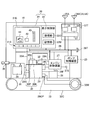
- FIG. 1 is a diagram illustrating an example of a work vehicle according to the present embodiment.
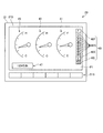
- FIG. 2 is an example of a diagram illustrating a state in which the monitor displays the first image.
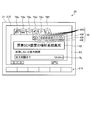
- FIG. 3 is an example of a diagram illustrating a state in which the monitor displays the second image.
- FIG. 1 is a diagram illustrating an example of a work vehicle 10 according to the present embodiment.
- FIG. 2 is an example of a diagram illustrating a state in which the monitor 20 displays the first image P1.
- FIG. 3 is an example of a diagram illustrating a state in which the monitor 20 displays the second image P2.
- the work vehicle 10 is, for example, a hydraulic excavator, a dump truck, a wheel loader, a bulldozer, a forklift, or the like, but is not limited thereto.
- the work vehicle 10 includes a monitor 20 as a display device for a work vehicle, an engine 29 as an internal combustion engine, and an exhaust gas processing device 30 that processes exhaust gas discharged from the engine 29.
- the work vehicle 10 includes a pump control device 23, a communication device 24, a position detection device 25, an engine control device 27, an in-vehicle signal line 28, a fuel tank 31, a urea water tank 32, a traveling It includes a device 33, a capacitor 34, an alternator 35, a key switch 36, a rotation speed detection sensor 38, and liquid level detection sensors 39F and 39A as detectors for detecting the amount of liquid.
- a detector for detecting the amount of liquid for example, an ultrasonic sensor capable of detecting the height of the liquid surface by detecting a float floating on the liquid can be used.
- the amount of liquid may be detected using another detector such as a liquid amount sensor that directly measures the amount of liquid.
- the monitor 20 is a device that displays an image.
- the monitor 20 includes a display unit 21 and a display control unit 22.
- the monitor 20 is installed in a driver's cab (not shown) of the work vehicle 10.
- the monitor 20 displays various types of information on the work vehicle 10 on the display unit 21 as images, for example.
- a urea water gauge 40, a warning icon 42, an abnormal part display icon 44, and the like are displayed on the screen 21 ⁇ / b> D of the display unit 21.
- the urea water gauge 40, the warning icon 42, and the abnormal part display icon 44 are all information related to the work vehicle 10.
- the urea water gauge 40 displays the remaining amount of urea water stored in the urea water tank 32.
- the warning icon 42 indicates that an abnormality has occurred in the exhaust gas processing device 30.
- the abnormal location display icon 44 indicates a location where an abnormality has occurred.
- the monitor 20 displays information related to the work vehicle 10.
- the monitor 20 displays an image captured by the camera on the screen 21D.
- the monitor 20 functions as an input device in addition to displaying various images on the screen 21D of the display unit 21.
- the monitor 20 includes an input device 21S below the screen 21D of the display unit 21.
- the input device 21 ⁇ / b> S is not limited to the lower side of the display unit 21, and may be in another place, or may be a separate body from the display unit 21.
- the input device 21S may be provided on a console in a driver's cab (not shown).
- the input device 21S has a plurality of push button switches arranged below the screen 21D and in the horizontal direction.
- processing to be executed by the work vehicle 10 include regeneration processing of the DPF (Diesel Particulate Filter) device 30P of the exhaust gas processing device 30 or output restriction release processing of the engine 29.
- the output restriction release processing temporarily limits the output in a state where the output of the engine 29 is restricted when a predetermined level of soot accumulates on the filter of the DPF device 30P or when urea water decreases to a predetermined level. It is a process to cancel.
- the processing to be executed by the work vehicle 10 is not limited to these.
- the work vehicle 10 restricts not only the engine 29 but also the hydraulic oil discharge amount of the hydraulic pump 29OP to reduce the hydraulic pressure.
- the output of the pump 29OP may also be limited.
- the work vehicle 10 is a hydraulic excavator that turns the upper swing body with an electric motor or a dump truck that drives wheels with an electric motor, the output should be limited as described above. Sometimes, the limitation of the output of these electric motors may be executed.
- the display unit 21 of the monitor 20 is, for example, a liquid crystal display device, but is not limited thereto.
- the monitor 20 also functions as an input device.
- the display unit 21 may include a touch panel on the screen 21D in order to cause the monitor 20 to exhibit the function as the input device.
- the display control unit 22 controls the operation of the display unit 21, performs image processing, and processes input from the input device 21S.
- the display control unit 22 includes, for example, a processing unit 22C and a storage unit 22M.
- the processing unit 22C is, for example, a combination of a CPU (Central Processing Unit) and a memory.
- the storage unit 22M is, for example, a RAM (Random Access Memory), a ROM (Read Only Memory), a flash memory, a hard disk drive, or the like, or a combination thereof.
- the storage unit 22M stores computer programs and data necessary for the display control unit 22 to execute the various processes described above, various setting data related to the operation of the work vehicle 10, and the like.
- the processing unit 22C implements various processes executed by the display control unit 22 by reading the computer program described above from the storage unit 22M and executing instructions described in the computer program.
- the display control unit 22 causes the display unit 21 to display either the first image P1 shown in FIG. 2 or the second image P2 shown in FIG. 3, which is different from the first image P1.
- the display control part 22 displays the apparatus information as information regarding the state of the exhaust gas processing apparatus 30 shown in FIG. 1 in the first image P1 and the second image P2.
- device information indicating the same content is displayed on the first image P1 and the second image P2 in the same display form.
- the apparatus information is a urea water gauge 40 indicating the remaining amount of urea water stored in the urea water tank 32 shown in FIG. The urea water gauge 40 is displayed on each of the first image P1 and the second image P2 displayed on the screen 21D of the display unit 21 at different timings.
- Urea water may be poorly distributed and may be difficult to obtain in some countries or regions. Therefore, the operator needs to constantly monitor the remaining amount of urea water consumed as the work vehicle 10 is operated.
- the display control unit 22 can alert the operator of the work vehicle 10 about the remaining amount of urea water. For this reason, the operator can easily grasp the remaining amount of urea water.
- the urea water gauge 40 displayed on both the first image P1 and the second image P2 is displayed in the same display form.
- the urea water gauge 40 displayed in the first image P1 switches the screen 21D to the second image P2
- the urea water gauge 40 displayed in the second image P2 is not urea. You can intuitively understand that it shows the remaining amount of water.
- the monitor 20 is electrically connected to the in-vehicle signal line 28.
- the monitor 20 communicates with the pump control device 23, the engine control device 27, and the like using a communication protocol applied to the in-vehicle signal line 28 such as CAN (Controller Area Network).
- CAN Controller Area Network
- the pump control device 23 is a device for controlling the swash plate angle of the hydraulic pump 29OP and adjusting the amount of hydraulic oil discharged to hydraulic equipment such as a hydraulic cylinder (not shown).
- the pump control device 23 is electrically connected to the in-vehicle signal line 28, and can communicate with the monitor 20 and the engine control device 27 that are also electrically connected to the in-vehicle signal line 28.
- the communication device 24 includes an antenna 24A.
- the communication device 24, the position detection device 25, and the information collection device 37 are incorporated in the communication processing device 37T.
- the communication processing device 37T is electrically connected to the in-vehicle signal line 28.
- the communication device 24 can communicate with the outside of the work vehicle 10.
- the communication device 24 is a communication modem, for example.
- the communication device 24 includes various control devices, various sensors, a communication terminal, and a communication modem.
- the communication device 24 performs wireless communication via the antenna 24A.
- the information collection device 37 connected to the communication device 24 collects operation information of the work vehicle 10 from, for example, sensors included in the work vehicle 10, the engine control device 27, the pump control device 23, and the like, and the communication device 24 and the antenna 24A. Send to the outside via.
- the operation information includes, for example, information on the remaining amount of urea water obtained from the liquid level detection sensors 39A and 39F.
- the communication device 24 receives information transmitted from the external management device to the work vehicle 10.
- the position detection device 25 includes a GPS antenna 25A.
- the GPS antenna 25A receives radio waves output from a plurality of GPS satellites constituting a GPS (Global Positioning System).
- the GPS antenna 25A outputs the received radio wave to the position detection device 25.
- the position detecting device 25 is mounted with the position detecting device 25 by converting the radio wave received by the GPS antenna 25A into an electric signal and calculating (positioning) its own position information, that is, the position of the position detecting device 25.
- the position information of the work vehicle 10 is obtained.
- the position information is information regarding the position of the work vehicle 10 and is coordinates of latitude, longitude, or altitude. In order for the position detection device 25 to measure its own position, not only GPS satellites but also other positioning satellites may be used.
- the position information of the work vehicle 10 obtained by the position detection device 25 is transmitted to the outside of the work vehicle 10 by the communication device 24 together with the operation information of the work vehicle 10.
- GNSS Global Navigation Satellite System
- the communication device 24 and the position detection device 25 are electrically connected to the information collection device 37.
- the information collecting device 37 is electrically connected to the in-vehicle signal line 28.
- the information collection device 37 generates information related to an abnormality that has occurred in the work vehicle 10 (hereinafter referred to as abnormality information as appropriate) or collects operation information.
- the information collection device 37 transmits the generated abnormality information to the outside of the work vehicle 10 via the communication device 24 and the antenna 24A, for example.
- the operation information includes information obtained from various sensors such as a pressure sensor, a rotation speed sensor 38, a temperature sensor, and liquid level detection sensors 39A and 39F (not shown).
- the information obtained from the pressure sensor includes the oil pressure of engine oil.
- the information obtained from the rotation speed sensor 38 includes the rotation speed (the number of rotations per unit time) of the engine 29.
- the information obtained from the temperature sensor includes the cooling water temperature of the engine 29.
- the position information (latitude, longitude, or altitude) of the work vehicle 10 detected by the position detection device 25 and information regarding an abnormality that has occurred in the work vehicle 10 are also transmitted to the outside of the work vehicle 10 by the communication device 24. Information about an abnormality that has occurred in the work vehicle 10 is also included in the operation information.
- the information regarding the abnormality that has occurred in the work vehicle 10 is, for example, a certain type of error code, the type of abnormality, or the occurrence time of the abnormality.
- the operation information is not limited to information related to an abnormality that has occurred in the work vehicle 10, and may include information indicating that the work vehicle 10 is operating normally, such as an operation time.
- the engine control device 27 controls the engine 29 and the exhaust gas processing device 30.
- the engine control device 27 is electrically connected to the in-vehicle signal line 28.
- the engine 29 controlled by the engine control device 27 is a diesel engine.
- the engine 29 is not limited to a diesel engine, and may be an internal combustion engine.
- the engine 29 drives the hydraulic pump 29OP to supply hydraulic oil to the hydraulic equipment included in the work vehicle 10.
- the exhaust gas treatment device 30 purifies the exhaust gas discharged by the engine 29 using a urea SCR device 30N using a DPF device 30P and a urea SCR (Selective Catalytic Reduction).
- the urea water supplied to the urea SCR device 30N is stored in the urea water tank 32.
- this embodiment shows the case where the exhaust gas processing system (urea SCR device 30N and urea water tank 32) using urea water is provided in the work vehicle 10, such an exhaust gas processing system is not provided.
- the work vehicle 10 is not excluded.
- the configuration or type of the exhaust gas processing device 30 varies depending on the type of the engine 29. Next, a control example of the engine control device 27 will be described.
- the engine control device 27 controls the amount of fuel supplied to the engine 29 based on the rotational speed of the crankshaft of the engine 29 detected by the rotational speed detection sensor 38 and the setting of the fuel adjustment dial 27S. In this way, the engine control device 27 controls the engine 29.
- the engine control device 27 controls the amount of urea water supplied to the urea SCR device 30N of the exhaust gas processing device 30 based on the amount of nitrogen oxides contained in the exhaust gas discharged from the engine 29.
- the exhaust gas treatment device 30 includes various sensors 30C.
- the various sensors 30C include, for example, a sensor that detects the amount of nitrogen oxide contained in the exhaust gas, a temperature sensor that detects the temperature of the exhaust gas, a sensor that detects ammonia in the urea SCR device 30N, and the like.
- the engine control device 27 supplies urea water from the urea water tank 32 to an injection device (not shown).
- the injection device is included in the configuration of the urea SCR device 30N.
- the urea SCR device 30N injects urea water into the exhaust gas from the injection device. Nitrogen oxides contained in the exhaust gas are reduced (decomposed) into nitrogen and water by urea water.
- the engine control device 27 obtains the remaining amount of urea water in the urea water tank 32 based on the detection value of the liquid level detection sensor 39A that detects the amount of urea water stored in the urea water tank 32.
- the engine control device 27 transmits the obtained remaining amount of urea water to the monitor 20.
- the monitor 20 displays, for example, the remaining amount of urea water on the urea water gauge 40 shown in FIG.
- the engine control device 27 obtains the remaining amount of fuel in the fuel tank 31 based on the detection value of the liquid level detection sensor 39F that detects the amount of fuel stored in the fuel tank 31.
- the engine control device 27 transmits the obtained remaining fuel amount to the monitor 20, and displays the remaining fuel amount on the fuel gauge 41 displayed on the screen 21D of the monitor 20, for example.
- the detection value of the liquid level detection sensor 39F that detects the amount of fuel may be directly transmitted to the monitor 20, and the remaining amount of fuel in the fuel tank 31 may be obtained by the processing unit 22C of the monitor 20, for example.
- the detection value of the liquid level detection sensor 39A for detecting the amount of urea water is directly transmitted to the monitor 20, and the remaining amount of urea water in the urea water tank 32 is obtained by, for example, the display control unit 22 of the monitor 20. Also good.
- the engine control device 27 transmits a “signal indicating that the engine 29 is in operation” to the monitor 20 via the in-vehicle signal line 28, and the monitor 20 measures the time during which the signal is received and performs cumulative operation. Ask for time.
- the engine control device 27 receives a signal from the rotational speed sensor 38 that detects the rotational speed of the engine 29, generates a “signal indicating that the engine 29 is in operation” based on the signal, and monitors the monitor 20 Send to. However, if for some reason the “signal indicating that the engine 29 is in operation” is not transmitted from the engine control device 27 to the monitor 20, the accumulated operation time can be obtained as follows.
- a signal (predetermined voltage) from the alternator 35 is transmitted to the monitor 20 via the signal line 35A.
- the monitor 20 measures the time during which the signal from the alternator 35 is received, and obtains the cumulative operation time.
- the signal of the alternator 35 may be always sent to the monitor 20 to measure the accumulated operation time.
- the signal of the rotation speed sensor 38 may be directly transmitted to the monitor 20 and the accumulated operation time may be measured using the signal of the rotation speed sensor 38.
- the monitor 20 can count the accumulated operation time.
- the fuel adjustment dial 27S, the sensor 30C, the rotation speed detection sensor 38, and the liquid level detection sensors 39A and 39F are electrically connected to the engine control device 27.
- the engine control device 27 can acquire set values from the fuel adjustment dial 27S, and can also acquire detection values from the various sensors 30C, the rotation speed detection sensor 38, and the liquid level detection sensors 39A and 39F. .
- the in-vehicle signal line 28 is, for example, CAN.
- the monitor 20, the pump control device 23, the engine control device 27, and the communication processing device 37T are electrically connected to the in-vehicle signal line 28.
- the monitor 20, the pump control device 23, the engine control device 27, and the communication processing device 37T can communicate with each other via an in-vehicle signal line 28.
- a terminal 28T is electrically connected to the in-vehicle signal line 28.
- a device having a communication function and a storage function such as a personal computer, a portable terminal, a storage medium, and a reading device can be used.
- the terminal 28T as a wireless local area network (LAN) device
- the operation information of the work vehicle 10 collected by the information collecting device 37 may be downloaded to the terminal device described above.
- the engine control device 27 is electrically connected to the monitor 20 via the in-vehicle communication line 28. Further, as described above, the liquid level detection sensors 39A and 39F and the rotation speed sensor 38 are electrically connected to the engine control device 27. With such a structure, the monitor 20 acquires information on the remaining amount of fuel or urea water detected by the liquid level detection sensors 39A and 39F via the engine control device 27, and the engine 29 is in operation. The operation signal which shows that can be received.
- the engine control device 27 acquires detection values indicating the amounts of fuel and urea water from the liquid level detection sensors 39A and 39F at predetermined intervals, and generates information indicating the remaining amounts of fuel and urea water. Further, the engine control device 27 transmits information indicating the remaining amount of fuel and urea water to the monitor 20 via the in-vehicle signal line 28 at a predetermined cycle.
- the traveling device 33 causes the work vehicle 10 to travel with the power generated by the engine 29.
- the traveling device 33 includes a hydraulic motor 33M and a crawler belt 33C.
- the hydraulic motor 33M is rotated by hydraulic oil supplied from a hydraulic pump 29OP driven by the engine 29.
- the hydraulic pump 29OP the discharge amount of hydraulic oil is controlled by the pump control device 23.
- the traveling device 33 causes the work vehicle 10 to travel when the hydraulic motor 33M rotates the crawler belt 33C.
- the traveling device 33 is not limited to the one provided with the crawler belt 33C.
- a device that transmits the power of the engine 29 to the wheels via a torque converter and a transmission may be used.
- the Work vehicle 10 includes a battery 34.
- the battery 34 is a secondary battery such as a lead storage battery or a nickel hydride storage battery, for example.
- the battery 34 supplies power to the starter 29S for starting the engine 29, and supplies power to various electronic devices included in the work vehicle 10 such as the monitor 20.
- the battery 34 charges the electricity generated by the alternator 35.
- the alternator 35 generates power by being driven in conjunction with the driving of the engine 29. The electricity generated by the alternator 35 is charged in the battery 34.
- the monitor 20 can determine whether or not the alternator 35 is operating normally by receiving a signal from the alternator 35. Further, as described above, the monitor 20 can also determine the accumulated operating time of the work vehicle 10 by measuring the time during which the signal from the alternator 35 is received.
- the electric power supplied from the battery 34 is supplied to electronic devices such as the starter 29S, the pump control device 23, the engine control device 27, the monitor 20, and the communication processing device 37T via the key switch 36.
- the key switch 36 is electrically connected to the battery 34, and the key switch 36 is electrically connected to the pump control device 23, the engine control device 27, the monitor 20, and the communication processing device 37T.
- As the key switch 36 a cylinder lock, a push button type, an immobilizer key using wireless communication, or the like can be used.
- the key switch 36 When the key switch 36 is turned on, power is supplied from the battery 34 to the pump control device 23, the engine control device 27, the monitor 20, and the communication processing device 37T.
- the key switch 36 is turned off, the electric power supplied from the battery 34 to the pump control device 23, the engine control device 27, the monitor 20, and the information collecting device 37 is cut off.
- the display unit 21 of the monitor 20 switches the first image P1 shown in FIG. 2 or the second image P2 shown in FIG. 3 and displays it on the screen 21D.
- the first image P1 is an image (normal image) displayed when the work vehicle 10 is in operation.
- the normal image is a screen including at least the cooling water temperature gauge 45, the fuel gauge 41, and the urea water gauge 40.
- the first image P1 is displayed on the screen 21D of the monitor 20 after the key switch 36 of the work vehicle 10 is turned on. After displaying the first image P1 on the screen 21D, the monitor 20 displays the first image P1 on the screen 21D unless an input to the monitor 20 or some event occurs in the work vehicle 10.
- the above-described input to the monitor 20 is an input for switching the image displayed on the screen 21D, for example.
- the operator can switch from the first image P1 to the second image P2 by operating the input device 21S.
- the urea water gauge 40 is displayed in the second image P2
- the abnormality information CI and the required time TL as shown in FIG. 3 are not displayed.
- information such as “normally operating” may be displayed in text. If the operator does not operate the input device 21S, the display control unit 22 automatically switches to the first image P1 that is a normal image after a predetermined time has elapsed.
- the display control unit 22 automatically switches the screen 21D from the first image P1 to the second image P2. If the operator does not operate the input device 21S, the display control unit 22 automatically switches the second image P2 to the first image P1 that is a normal image after a predetermined time has elapsed.
- the conditions necessary for switching the display of the first image P1 on the screen 21D are not limited to these.
- the first image P1 includes a fuel gauge 41 indicating the remaining amount of fuel, a hydraulic oil temperature gauge 43 indicating the temperature of the hydraulic oil, and a cooling water temperature gauge 45 indicating the temperature of the cooling water of the engine 29.
- the needle shown on the fuel gauge 41 points closer to F.
- the needle indicated on the fuel gauge 41 indicates the one closer to E.
- the needle indicated on the hydraulic oil temperature gauge 43 or the cooling water temperature gauge 45 points closer to H, it indicates that the temperature of the hydraulic oil or the cooling water is high.
- the needle shown in the hydraulic oil temperature gauge 43 or the cooling water temperature gauge 45 points to the side closer to C, it indicates that the temperature of the hydraulic oil or the cooling water is low.
- the first image P1 includes an accumulated operation time 47 indicating the accumulated operation time of the engine 29.
- the accumulated operation time 47 is obtained based on the signal transmitted from the engine control device 27 to the monitor 20 as described above.
- the hydraulic oil temperature gauge 43 may not be included in what is displayed in the first image P1.
- each gauge 41, 43, 45 may display a state quantity in other display forms like a pie chart or a bar graph instead of a needle type gauge.
- the urea water gauge 40 described above is also included in the first image P1.
- the remaining amount of urea water indicated by the urea water gauge 40 is device information related to the state of the exhaust gas treatment device 30 as described above.
- the display control unit 22 of the monitor 20 shown in FIG. 1 displays the remaining amount of urea water indicated by the urea water gauge 40 on the first image P2 as device information.
- the accumulated operation time 47 indicates the accumulated value of the time that the engine 29 of the work vehicle 10 has been operated so far as the accumulated operation time of the work vehicle 10.
- the first image P1 displays at least the accumulated operation time as information on the work vehicle 10. Since the first image P1 is displayed when the work vehicle 10 is in operation, the first image P1 may include information necessary for operation of the work vehicle 10 in addition to the accumulated operation time. As such information, for example, type information regarding various mode settings such as an operation mode in which the fuel consumption of the work machine 10 is prioritized or an operation mode in which the excavation force of the work machine 1 is prioritized, or a mode setting of the traveling speed of the work machine 10. Type information and the like. If the work vehicle 10 has many opportunities to travel, such as a dump truck or a wheel loader, for example, the accumulated travel distance or travel speed is also necessary information when the work vehicle 10 is in operation.
- the urea water gauge 40 is stored in the urea water tank 32 between a state F in which the urea water tank 32 is filled with urea water and an E indicating that the urea water in the urea water tank 32 is empty.
- a plurality of indicators 40G indicating the position of the level of the urea water being displayed are displayed.
- a state F in which the urea water is filled is indicated by an icon 40F
- E indicating a state in which the urea water is empty is indicated by an icon 40E.
- the urea water gauge 40 is preferably displayed at a position adjacent to the fuel gauge 41.
- the urea water or fuel is managed from a common viewpoint that it is consumed and needs to be replenished sequentially. Therefore, each remaining amount can be easily managed by displaying the urea water gauge 40 and the fuel gauge 41 at close positions.
- the urea water gauge 40 has an icon 40I indicated by a picture meaning that it is information related to the urea SCR device 30N.
- the pattern of the icon 40I has the same form as that of the tab TBd shown in FIG.
- the display control unit 22 changes the color of the icon 40I from the normal time or blinks to indicate to the operator that the urea water is decreasing. .
- the display control unit 22 changes the color of the icon 40I or causes the icon 40I to blink.
- the color displayed when the urea water decreases and the color displayed when an abnormality is detected are made different so that the operator or serviceman can use any phenomenon. It is possible to clearly distinguish whether this is happening.
- the plurality of indicators 40G are lit according to the remaining amount of urea water in the urea water tank 32, that is, the position of the urea water level.
- the indicator 40G on the icon 40F side is lit. 2 and 3 show a state in which an indicator 40G indicated by hatching is lit (the same applies hereinafter).
- the indicator 40G on the icon 40F side sequentially turns off according to the amount of decrease in the urea water.
- the urea water gauge 40 displays the remaining amount of urea water stored in the urea water tank 32. That is, the urea water gauge 40 displays the remaining amount of urea water by the number of indicators 40G that are lit. Specifically, the remaining amount of urea water decreases as the number of lit indicators 40G decreases.
- the operator of the work vehicle 10 can always check the remaining amount of urea water during work. For this reason, the operator can arrange or replenish urea water appropriately according to the remaining amount of urea water.
- the second image P2 shown in FIG. 3 displays a plurality of types of information separately.
- the second image P2 displays a plurality of types of information by switching between tabs TBa, TBb, TBc, TBd, TBe, and TBf.
- the tab can be switched by operating the input device 21S.
- the tab TBd is selected.
- the tab TBd includes information regarding the urea SCR device 30N.
- the tab TBa includes information related to the environment such as a history of fuel consumption
- the tab TBb includes information related to the manual of the work vehicle 10
- the tab TBc includes information related to the DPF device 30P
- the tab TBe relates to the hydraulic system.
- the tab TBf includes information regarding the setting of the monitor 20.
- the tab may be provided with a tag including information related to the operation setting of the work vehicle 10 or information related to the maintenance history of the work machine 10.
- information related to the operation setting of the work vehicle 10 or information related to the maintenance history of the work machine 10.
- the content and number of the plurality of types of information included in the second image P2 are not limited to these, it is preferable that information regarding the exhaust gas processing device 30 is included.
- the second image P2 shown in FIG. 3 is an example showing that an abnormality occurs in the urea SCR device 30N, and that the output of the engine 29 is limited (state information) unless processing is performed for this abnormality.
- the transition to the second image P2 can be executed even if no abnormality has occurred in the urea SCR device 30N.
- the second image P2 may indicate that the urea SCR device 30N or the like is operating normally (status information).
- at least the urea water gauge 40 having the same display form as the urea water gauge 40 of the first image P1 is displayed in the second image P2.
- the content of the abnormality may be characters as shown in FIG. 3 as the abnormality information CI. It may be a symbol or symbol that allows the contents of the abnormality to be intuitively viewed.
- the second image P2 also displays a required time TL until the output of the engine 29 is limited as one of the state information. In this example, even if 12 h (hours) 34 m (minutes) elapses, if the abnormality that has occurred in the urea SCR device 30N is not treated, the engine controller 27 outputs the engine 29. Will be limited.
- the display control unit 22 of the monitor 20 shown in FIG. 1 also displays the remaining amount of urea water as device information on the second image P2.
- the display control unit 22 displays the remaining amount of urea water on the second image P2 in the same display form as the first image P1.
- the display control unit 22 displays the urea water gauge 40 on the second image P2 by the same display form with the same contents as the urea water gauge 40 in the first image P1. That is, the urea water gauge 40 displayed on the second image P2 is similar to the urea water gauge 40 displayed on the first image P1 between the icon 40I, the icon 40E, the icon 40F, and the icon 40E and the icon 40F. It has a plurality of indicators 40G provided.
- the urea water gauge 40 is arranged vertically, but in the second image P2, the urea water gauge 40 is arranged horizontally. That is, the urea water gauge 40 has the display form (design) similar to the display form (design) displayed on the first image P1, and the icon 40E, the icon 40F, and the indicator 40G are displayed on the second image P2. Also in the second image P2, the urea water gauge 40 may be arranged vertically in the same display form as the first image P1. In the present embodiment, the first image P1 and the second image have different directions of the urea water gauge 40 in the vertical and horizontal directions, but the form, configuration, and information to be displayed of the urea water gauge 40 are the same.
- the urea water gauge 40 displayed in the first image P1 and the urea water gauge 40 displayed in the second image P2 differ only in the overall size, and the form, configuration and information to be displayed of the urea water gauge 40 If they are the same, they are displayed in the same display form.
- the form, configuration, and information to be displayed of the urea water gauge 40 include at least one of the design and color indicated by the pattern of the icon 40I, at least one of the design and color indicated by the icons 40E and 40F, and at least one of the design and color indicated by the indicator 40G. On the other hand, the number of segments of the indicator 40G.
- the display control unit 22 displays the device information (the remaining amount of urea water in this example) in the same display form on the first image P1 and the second image P2, so that the operator of the work vehicle 10 Makes it easier to grasp the remaining amount of urea water.
- the operator is familiar with the display form of the urea water gauge 40 by the first image P1 which is an image (normal image) displayed when the work machine 10 is in operation. Therefore, the urea water gauge 40 expressed in the familiar display form is displayed in the similar display form on the second image P2 that is not frequently seen, so that the operator has the remaining amount of urea water first. It is possible to intuitively recognize that the two images P2 are displayed without being confused. That is, even if the image displayed on the screen 21D of the monitor 20 transitions between the first image P1 and the second image P2, the operator can reliably grasp the remaining amount of urea water. As a result, the operator can arrange or replenish urea water at an appropriate timing. Further, it is possible to perform work progress management such as adjusting the operating time of the work machine 10 in accordance with the remaining amount of urea water.
- the operator of the work vehicle 10 Since the second image P2 indicates that an abnormality has occurred in the urea SCR device 30N, the operator of the work vehicle 10 has detected an abnormality in the urea SCR device 30N from the information indicated in the second image P2. It is possible to grasp what has occurred and the content of the abnormality that has occurred. In the second image P2, the remaining amount of urea water indicated by the urea water gauge 40 is shown together with the abnormality of the urea SCR device 30N. For this reason, the operator can visually recognize the relationship between the two intuitively. That is, the operator can understand the content of the abnormality more quickly and accurately by comparing the abnormality of the urea SCR device 30N with the remaining amount of urea water.
- the urea water gauge 40 is displayed in the second image P2 even if no abnormality has occurred in the urea SCR device 30N. Therefore, even when the urea SCR device 30N is operating normally, the operator can confirm that the urea SCR device 30N is operating normally and at the same time grasp the remaining amount of urea water. it can.
- the operator can intuitively understand that more than half of the urea water remains in the urea water tank 32 by visually checking the urea water gauge 40 shown in the second image P2. For this reason, the operator can determine that the abnormality occurring in the urea SCR device 30N is not caused by the shortage of the remaining amount of the urea water when looking at the urea water gauge. In addition, the operator can easily identify the cause of the abnormality occurring in the urea SCR device 30N by reading the abnormality information CI indicated by characters in the second image P2.
- the operator visually recognizes the urea water gauge 40, thereby causing the urea SCR device 30N to have a shortage of urea water. It can be determined that an abnormality may have occurred.
- the operator can easily identify the cause of the abnormality occurring in the urea SCR device 30N by reading the information indicated by characters in the second image P2.
- the urea water gauge 40 the remaining amount of urea water is sufficient, but the abnormality information CI of the second image P2 indicates that an abnormality due to the insufficient amount of urea water has occurred.
- the operator can determine that the causes of the abnormality indicated by both are different. In this case, for example, it can be estimated that an abnormality has occurred in the in-vehicle signal line 28 or the liquid level detection sensor 39A shown in FIG.
- the urea water gauge 40 the remaining amount of urea water is insufficient, but the abnormality information CI of the second image P2 indicates that an abnormality other than the insufficient amount of urea water has occurred.
- the display control unit 22 displays the remaining amount of urea water and the abnormality occurring in the urea SCR device 30N in the same image (second image in the present embodiment), thereby determining abnormality. , And the accuracy when identifying an abnormality can be improved and prompt response can be achieved.
- the display control unit 22 shown in FIG. 1 abnormally detects the remaining amount of urea water (detection) by the liquid level detection sensor 39A due to disconnection of the in-vehicle signal line 28 or failure of the liquid level detection sensor 39A itself.
- the device information of the second image P2 that is, the urea water gauge 40
- the urea water gauge 40 may be displayed in a display form different from normal. By doing so, it is possible to notify the operator of the work vehicle 10 that the remaining amount of urea water displayed by the urea water gauge 40 may not be a correct value.
- the display control unit 22 changes the display form of the urea water gauge 40 depending on whether the detection abnormality has occurred or the detection abnormality has occurred. It is possible to vary the case where no abnormality occurs or to blink the urea water gauge 40. Further, as described above, the display control unit 22 may change the display form of the icon 40I shown in FIG. 3 between the normal time and the abnormal time. For example, the display control unit 22 can change the color of the icon 40I or blink the icon 40I.
- the display control unit 22 can clearly indicate that a detection abnormality has occurred toward the operator.
- the display control unit 22 changes the color of the icon 40I from the normal time or causes the icon 40I to blink.
- the display control unit 22 changes the color of the icon 40I from the normal time or causes the icon 40I to blink.
- the color of the icon 40I it is possible to clearly distinguish which phenomenon is occurring by making the color displayed when urea water decreases and the color displayed at the time of detection abnormality different. be able to.
- changing the display form of the urea water gauge 40 in the three states of normal, abnormal detection, or decrease of the urea water is not only the state in which the second image P1 is displayed, but also the first. The same may be performed even when the image P1 is displayed.
- the display control unit 22 of the monitor 20 acquires, for example, a signal indicating that the ultrasonic sensor used as the liquid level detection sensor 39A has performed inappropriate detection via the in-vehicle signal line 28, that is, when a detection abnormality occurs.
- the urea water gauge 40 is displayed in a display form different from that in the normal state.
- the engine control device 27, etc. urea water by the liquid level detection sensor 39A This is a case where an abnormality has occurred in the detection of the remaining amount, and corresponds to a detection abnormality.
- An abnormality that has occurred in the in-vehicle signal line 28 is detected by, for example, a communication control unit (not shown) included in the monitor 20.
- the display control unit 22 displays the urea water gauge 40 in a display form that is different from that in the normal state. In this way, the display control unit 22 changes the display form of the urea water gauge 40 when an abnormality occurs in the detection of the remaining amount of urea water by the liquid level detection sensor 39A.
- the possibility that the remaining amount of urea water shown in FIG. As described above, the operator can easily distinguish the cause of the abnormality by making the display form of the urea water gauge 40 different from the normal state when the detection abnormality occurs or when the urea water decreases.
- the urea water gauge 40 includes a plurality of indicators 40G, but the form indicating the remaining amount of urea water is not limited to the urea water gauge 40.
- the remaining amount of urea water may be indicated by a numerical value, or the height of the urea water level in the urea water tank 32 may be indicated by a ratio or the like.
- the device information related to the state of the exhaust gas treatment device is the remaining amount of urea water, but the device information is not limited to this.
- the device information is not limited to this.
- at least one of the temperature of urea water and the quality of urea water may be used as device information.
- information on the state of a supply system that supplies urea water to the exhaust gas may be used as device information.
- Information about the state of the supply system includes, for example, information about an injection device that injects urea into exhaust gas, information about piping that supplies urea water, and information about a device that supplies urea water to the injection device.
- information about a sensor or the like that detects ammonia in the urea SCR device 30N may be used as device information.
- Information relating to the state of the DPF device 30P shown in FIG. 1 may be used as device information.
- the differential pressure between the inlet and outlet of the filter provided in the DPF device 30P, the inlet temperature and outlet temperature of the DOC (Diesel Oxygen Catalyst) provided in the DPF device 30P may be used as device information.
- Information relating to a sensor that measures the intake air amount of the engine 29, a sensor that detects the amount of nitrogen oxides contained in the exhaust gas, and the like may be used as device information.
- the device information displayed on the second image P2 is information related to the state of the DPF device 30P
- the device information is displayed on the first image P1 in the same display form. 3 is preferably displayed together with information shown when the tab TBc of the second image P2 shown in FIG. 3 is selected.
- the display control unit 22 of the monitor 20 displays either the first image P1 or the second image P2 different from the first image P1, and device information regarding the state of the exhaust gas processing device 30 is displayed.
- the first image P1 and the second image P2 are displayed.
- the present embodiment alerts the operator of the work vehicle 10 about the state of the exhaust gas treatment device 30 in the work vehicle 10 including the engine 29 and the exhaust gas treatment device 30 that treats the exhaust gas discharged from the engine 29. Can be easier.
- the display control unit 22 displays information on the remaining amount of urea water in the first image P1 and the second image P2, so that the operator pays attention to the remaining amount of urea water. You can arrange and replenish urea water. Even if the screen 21D of the monitor 20 is switched from the first image P1 to the second image P1, the device information is displayed on the second image P1 in the same display manner as the device information included in the first image P1. Therefore, the operator can always recognize and acquire the information indicated by the device information intuitively. As described above, according to the present embodiment, it is possible to reduce the possibility that processing for an abnormality that has occurred in the exhaust gas processing device 30 is delayed or that opportunities for maintenance and inspection are missed.
- the display control unit 22 displays, as device information related to the state of the DPF device 30P, for example, information related to filter clogging provided in the DPF device 30P on the first image P1 and the second image P2, the operator Attention will be paid to clogging.
- the device information is displayed on the screen 21D where the tab TBc of the second image P2 is selected.
- urea water gauge 40 when the urea water gauge 40 is displayed on the first image P1 and is switched to the second image P2, no matter what tab TBa, TBb, TBc, TBd, TBe, TBf is selected, urea is displayed on the screen 21D.
- the water gauge 40 may be displayed in the same display form as the first image P1.
Landscapes
- Engineering & Computer Science (AREA)
- Chemical & Material Sciences (AREA)
- Combustion & Propulsion (AREA)
- Mechanical Engineering (AREA)
- Transportation (AREA)
- Chemical Kinetics & Catalysis (AREA)
- General Engineering & Computer Science (AREA)
- Health & Medical Sciences (AREA)
- Toxicology (AREA)
- Exhaust Gas After Treatment (AREA)
- Component Parts Of Construction Machinery (AREA)
- Instrument Panels (AREA)
Abstract
Description
図1は、本実施形態に係る作業車両10の一例を示す図である。図2は、モニタ20が第1画像P1を表示する状態を示す図の一例である。図3は、モニタ20が第2画像P2を表示する状態を示す図の一例である。作業車両10は、例えば、油圧ショベル、ダンプトラック、ホイールローダ、ブルドーザ又はフォークリフト等であるが、これらに限定されるものではない。作業車両10は、作業車両用表示装置としてのモニタ20と、内燃機関としてのエンジン29と、エンジン29が排出した排気ガスを処理する排気ガス処理装置30とを備える。この他に、作業車両10は、ポンプ制御装置23と、通信装置24と、位置検出装置25と、エンジン制御装置27と、車内信号線28と、燃料タンク31と、尿素水タンク32と、走行装置33と、蓄電器34と、オルタネータ35と、キースイッチ36と、回転速度検出センサ38と、液体の量を検出する検出器としての液面検出センサ39F、39Aとを含む。液体の量を検出する検出器として、例えば液体に浮かべたフロートを検出することで液面の高さをとらえることが可能な超音波センサを用いることができる。また、液面を検出するのではなく、液体の量を直接計測するような液量センサ等、他の検出器を用いて液体の量を検出するようにしてもよい。
20 モニタ
20 制御装置
21D 画面
21S 入力装置
21 表示部
22 表示制御部
22C 処理部
22M 記憶部
23 ポンプ制御装置
27 エンジン制御装置
28 車内信号線
29 エンジン
29OP 油圧ポンプ
29S 燃料調整ダイヤル
30 排気ガス処理装置
30C センサ
30N 尿素SCR装置
30P DPF装置
32 尿素水タンク
35 オルタネータ
35S 電圧センサ
36 キースイッチ
37T 通信処理装置
38 回転速度検出センサ
39A、39F 液面検出センサ
40 尿素水ゲージ
40G インジケータ
41 燃料ゲージ
P1 第1画像
P1 第2画像
Claims (8)
- 動力を発生する内燃機関及び前記内燃機関が排出した排気ガスを、尿素水を用いて処理する排気ガス処理装置を有する作業車両に備えられる表示装置であり、
画像を表示する表示部と、
前記表示部に、第1画像又は前記第1画像とは異なる第2画像のいずれか一方を表示させる表示制御部と、を含み、
前記表示制御部は、前記排気ガス処理装置の状態に関する同一内容の装置情報を、前記第1画像と前記第2画像とに表示する、作業車両用表示装置。 - 前記表示制御部は、
前記装置情報を、同様の表示形態で前記第1画像及び前記第2画像に表示させる、請求項1に記載の作業車両用表示装置。 - 前記装置情報は、前記作業車両に備えられたタンクに溜められて、前記排気ガス処理装置に供給される尿素水の残量である、請求項1又は請求項2に記載の作業車両用表示装置。
- 前記表示制御部は、
前記尿素水の残量の検出に異常が発生した場合、前記装置情報を、正常である場合とは異ならせて表示させる、請求項3に記載の作業車両用表示装置。 - 前記表示制御部は、
前記第1画像を前記作業車両の作業中に表示し、前記作業車両が作業をしていないときに、前記第2画像を表示可能とする、請求項1から請求項4のいずれか1項に記載の作業車両用表示装置。 - 前記第1画像は、前記作業車両の稼働時に表示される通常画像であって、
前記第2画像は、入力装置からの入力又は前記作業車両に発生したイベントによって前記通常画像から切り替えられて表示される画像である、請求項1から請求項5のいずれか1項に記載の作業車両用表示装置。 - 動力を発生する内燃機関及び前記内燃機関が排出した排気ガスを処理する排気ガス処理装置を有する作業車両に備えられる表示装置であり、
画像を表示する表示部と、
前記表示部に、第1画像又は前記第1画像とは異なる第2画像のいずれか一方を表示させる表示制御部と、を含み、
前記表示制御部は、前記排気ガス処理装置に供給される尿素水の残量に関する同一内容の装置情報を、同様の表示形態で前記第1画像と前記第2画像とに表示する、作業車両用表示装置。 - 動力を発生する内燃機関と、
前記内燃機関が排出した排気ガスを、尿素水を用いて処理する排気ガス処理装置と、
請求項1から請求項7のいずれか1項に記載の作業車両用表示装置と、
を含む、作業車両。
Priority Applications (7)
| Application Number | Priority Date | Filing Date | Title |
|---|---|---|---|
| US14/372,090 US9500114B2 (en) | 2014-02-18 | 2014-02-18 | Work vehicle display device and work vehicle |
| DE112014000057.4T DE112014000057B4 (de) | 2014-02-18 | 2014-02-18 | Arbeitsfahrzeug-Displayvorrichtung und Arbeitsfahrzeug |
| PCT/JP2014/053785 WO2015025535A1 (ja) | 2014-02-18 | 2014-02-18 | 作業車両用表示装置及び作業車両 |
| KR1020157009503A KR101721784B1 (ko) | 2014-02-18 | 2014-02-18 | 작업 차량용 표시 장치 및 작업 차량 |
| JP2014517285A JP5876571B2 (ja) | 2014-02-18 | 2014-02-18 | 作業車両用表示装置及び作業車両 |
| IN2954DEN2015 IN2015DN02954A (ja) | 2014-02-18 | 2014-02-18 | |
| CN201480000652.3A CN105008690B (zh) | 2014-02-18 | 2014-02-18 | 作业车辆用显示装置和作业车辆 |
Applications Claiming Priority (1)
| Application Number | Priority Date | Filing Date | Title |
|---|---|---|---|
| PCT/JP2014/053785 WO2015025535A1 (ja) | 2014-02-18 | 2014-02-18 | 作業車両用表示装置及び作業車両 |
Publications (1)
| Publication Number | Publication Date |
|---|---|
| WO2015025535A1 true WO2015025535A1 (ja) | 2015-02-26 |
Family
ID=52483327
Family Applications (1)
| Application Number | Title | Priority Date | Filing Date |
|---|---|---|---|
| PCT/JP2014/053785 Ceased WO2015025535A1 (ja) | 2014-02-18 | 2014-02-18 | 作業車両用表示装置及び作業車両 |
Country Status (7)
| Country | Link |
|---|---|
| US (1) | US9500114B2 (ja) |
| JP (1) | JP5876571B2 (ja) |
| KR (1) | KR101721784B1 (ja) |
| CN (1) | CN105008690B (ja) |
| DE (1) | DE112014000057B4 (ja) |
| IN (1) | IN2015DN02954A (ja) |
| WO (1) | WO2015025535A1 (ja) |
Cited By (4)
| Publication number | Priority date | Publication date | Assignee | Title |
|---|---|---|---|---|
| JP2019015191A (ja) * | 2017-07-04 | 2019-01-31 | 三菱ロジスネクスト株式会社 | 異常報知装置、その装置を搭載する作業車両、およびフォークリフト |
| WO2019026648A1 (ja) * | 2017-07-31 | 2019-02-07 | ヤンマー株式会社 | 作業車両 |
| JP2021031854A (ja) * | 2019-08-16 | 2021-03-01 | 株式会社クボタ | 作業機 |
| JP2023105675A (ja) * | 2022-01-19 | 2023-07-31 | 株式会社小松製作所 | 遠隔表示システム及び遠隔表示方法 |
Families Citing this family (13)
| Publication number | Priority date | Publication date | Assignee | Title |
|---|---|---|---|---|
| KR101691317B1 (ko) * | 2013-11-19 | 2017-01-09 | 가부시키가이샤 고마쓰 세이사쿠쇼 | 작업 차량의 표시 장치 및 그 표시 방법 |
| US10308108B2 (en) * | 2015-03-30 | 2019-06-04 | Kubota Corporation | Working machine |
| JP6217691B2 (ja) * | 2015-05-29 | 2017-10-25 | コニカミノルタ株式会社 | 表示制御方法、表示制御プログラムおよび表示制御装置 |
| JP6929026B2 (ja) * | 2016-07-22 | 2021-09-01 | 株式会社クボタ | 作業車 |
| JP6605524B2 (ja) * | 2017-03-27 | 2019-11-13 | 日立建機株式会社 | 作業機械の稼働状態表示システム |
| EP3617410A4 (en) * | 2017-04-26 | 2020-06-24 | Sumitomo (S.H.I.) Construction Machinery Co., Ltd. | SHOVEL, SHOVEL MANAGEMENT DEVICE AND AUXILIARY DEVICE FOR SHOVEL MANAGEMENT |
| US10843702B2 (en) * | 2018-06-06 | 2020-11-24 | Ford Global Technologies, Llc | Methods and systems for oil leak determination |
| WO2020086326A1 (en) * | 2018-10-23 | 2020-04-30 | Zonar Systems, Inc. | System and method for facilitating regeneration of particulate filters in a fleet of vehicles |
| CN113450473B (zh) * | 2021-06-28 | 2022-10-04 | 智联万维科技有限公司 | 尿素添加点位识别系统 |
| CN114000937B (zh) * | 2021-10-29 | 2023-03-24 | 潍柴动力股份有限公司 | 尿素结晶自动识别清理装置及其控制方法 |
| USD1061552S1 (en) | 2022-12-21 | 2025-02-11 | Caterpillar Inc. | Display screen or portion thereof with graphical user interface |
| KR20240162906A (ko) * | 2023-05-09 | 2024-11-18 | 현대자동차주식회사 | 연료 저장 시스템 및 연료 잔여량 검출 방법 |
| US12424075B2 (en) * | 2024-01-31 | 2025-09-23 | Ford Global Technologies, Llc | Vehicle filtering hub |
Citations (4)
| Publication number | Priority date | Publication date | Assignee | Title |
|---|---|---|---|---|
| JP2005248646A (ja) * | 2004-03-08 | 2005-09-15 | Hitachi Constr Mach Co Ltd | 建設機械の表示装置、表示方法、表示制御プログラム、表示制御プログラムを記録したコンピュータ読み取り可能な記録媒体 |
| DE102007032257A1 (de) * | 2007-07-11 | 2009-01-15 | Volkswagen Ag | Verfahren zum Anzeigen von den Betrieb eines Fahrzeugs betreffende Informationen und Anzeigeeinrichtung für ein Fahrzeug |
| JP2009127521A (ja) * | 2007-11-22 | 2009-06-11 | Hitachi Constr Mach Co Ltd | 作業車両の排ガス後処理装置 |
| JP2012072617A (ja) * | 2010-09-29 | 2012-04-12 | Hitachi Constr Mach Co Ltd | 作業機械の表示システム |
Family Cites Families (20)
| Publication number | Priority date | Publication date | Assignee | Title |
|---|---|---|---|---|
| JP3703575B2 (ja) * | 1996-08-30 | 2005-10-05 | 日立建機株式会社 | 作業機械の稼動可能残時間予知装置 |
| DE10139142A1 (de) * | 2001-08-09 | 2003-02-20 | Bosch Gmbh Robert | Abgasbehandlungseinheit und Messvorrichtung zur Ermittlung einer Konzentration einer Harnstoff-Wasser-Lösung |
| DE102004021660A1 (de) * | 2004-05-03 | 2006-05-11 | Siemens Ag | Kraftfahrzeug |
| JP4466580B2 (ja) * | 2005-10-13 | 2010-05-26 | 株式会社デンソー | 車両用表示装置 |
| JP4329866B1 (ja) * | 2008-03-07 | 2009-09-09 | トヨタ自動車株式会社 | 車両の制御装置、制御方法およびその方法をコンピュータに実行させるプログラムならびにそのプログラムを記録した記録媒体 |
| DE102009010888B4 (de) * | 2009-02-27 | 2012-02-02 | Continental Automotive Gmbh | Verfahren und Vorrichtung zur Steuerung eines SCR-Abgasnachbehandlungssystems einer Brennkraftmaschine |
| JP2010261373A (ja) * | 2009-05-08 | 2010-11-18 | Kobelco Contstruction Machinery Ltd | 作業機械 |
| DE102010013696A1 (de) * | 2010-04-01 | 2011-10-06 | Emitec Gesellschaft Für Emissionstechnologie Mbh | Verfahren zum Betrieb einer Abgashandlungsvorrichtung |
| CN101830203B (zh) * | 2010-05-13 | 2011-11-09 | 北汽福田汽车股份有限公司 | 车辆控制信息处理方法和装置、车辆控制系统以及车辆 |
| DE102010026600A1 (de) | 2010-07-08 | 2012-01-12 | Claas Selbstfahrende Erntemaschinen Gmbh | Überwachungsvorrichtung für einen Verbrennungsmotor |
| DE102010035008A1 (de) * | 2010-08-20 | 2012-02-23 | Emitec Gesellschaft Für Emissionstechnologie Mbh | Harnstoffbehälter mit Ultraschallsensor |
| DE102010062333A1 (de) * | 2010-12-02 | 2012-06-06 | Robert Bosch Gmbh | Vorrichtung zur Versorgung eines Abgasnachbehandlungssystems mit einem Reduktionsmittel |
| KR20130058995A (ko) | 2011-11-28 | 2013-06-05 | 현대자동차주식회사 | 차량의 클러스터 |
| US8984867B2 (en) * | 2012-04-10 | 2015-03-24 | GM Global Technology Operations LLC | Nitrogen dioxide generation diagnostic for a diesel after-treatment system |
| WO2014002866A1 (ja) * | 2012-06-28 | 2014-01-03 | ボッシュ株式会社 | 異常診断装置及び内燃機関の排気浄化装置 |
| JP5907123B2 (ja) * | 2012-07-13 | 2016-04-20 | 井関農機株式会社 | スート堆積演算表示装置 |
| US9008880B2 (en) * | 2013-07-15 | 2015-04-14 | Ford Global Technologies, Llc | Method and system for a plug-in hybrid electric vehicle |
| JP6505356B2 (ja) * | 2013-07-17 | 2019-04-24 | 住友建機株式会社 | ショベル |
| US20150096285A1 (en) * | 2013-10-03 | 2015-04-09 | Cummins Emission Solutions Inc. | System, apparatus, and methods for performing a quality diagnostic of an aqueous urea solution |
| DE112013000265B4 (de) * | 2013-12-11 | 2018-07-26 | Komatsu Ltd. | Arbeitsmaschine, Steuersystem für eine Arbeitsmaschine und Steuerverfahren für eine Arbeitsmaschine |
-
2014
- 2014-02-18 CN CN201480000652.3A patent/CN105008690B/zh active Active
- 2014-02-18 DE DE112014000057.4T patent/DE112014000057B4/de active Active
- 2014-02-18 KR KR1020157009503A patent/KR101721784B1/ko active Active
- 2014-02-18 US US14/372,090 patent/US9500114B2/en active Active
- 2014-02-18 WO PCT/JP2014/053785 patent/WO2015025535A1/ja not_active Ceased
- 2014-02-18 IN IN2954DEN2015 patent/IN2015DN02954A/en unknown
- 2014-02-18 JP JP2014517285A patent/JP5876571B2/ja active Active
Patent Citations (4)
| Publication number | Priority date | Publication date | Assignee | Title |
|---|---|---|---|---|
| JP2005248646A (ja) * | 2004-03-08 | 2005-09-15 | Hitachi Constr Mach Co Ltd | 建設機械の表示装置、表示方法、表示制御プログラム、表示制御プログラムを記録したコンピュータ読み取り可能な記録媒体 |
| DE102007032257A1 (de) * | 2007-07-11 | 2009-01-15 | Volkswagen Ag | Verfahren zum Anzeigen von den Betrieb eines Fahrzeugs betreffende Informationen und Anzeigeeinrichtung für ein Fahrzeug |
| JP2009127521A (ja) * | 2007-11-22 | 2009-06-11 | Hitachi Constr Mach Co Ltd | 作業車両の排ガス後処理装置 |
| JP2012072617A (ja) * | 2010-09-29 | 2012-04-12 | Hitachi Constr Mach Co Ltd | 作業機械の表示システム |
Cited By (8)
| Publication number | Priority date | Publication date | Assignee | Title |
|---|---|---|---|---|
| JP2019015191A (ja) * | 2017-07-04 | 2019-01-31 | 三菱ロジスネクスト株式会社 | 異常報知装置、その装置を搭載する作業車両、およびフォークリフト |
| WO2019026648A1 (ja) * | 2017-07-31 | 2019-02-07 | ヤンマー株式会社 | 作業車両 |
| JP2019027365A (ja) * | 2017-07-31 | 2019-02-21 | ヤンマー株式会社 | 作業車両 |
| US11028746B2 (en) | 2017-07-31 | 2021-06-08 | Yanmar Power Technology Co., Ltd. | Work vehicle including diesel particulate filter (DPF) regeneration control |
| JP2021031854A (ja) * | 2019-08-16 | 2021-03-01 | 株式会社クボタ | 作業機 |
| JP7254660B2 (ja) | 2019-08-16 | 2023-04-10 | 株式会社クボタ | 作業機 |
| JP2023105675A (ja) * | 2022-01-19 | 2023-07-31 | 株式会社小松製作所 | 遠隔表示システム及び遠隔表示方法 |
| JP7805794B2 (ja) | 2022-01-19 | 2026-01-26 | 株式会社小松製作所 | 遠隔表示システム及び遠隔表示方法 |
Also Published As
| Publication number | Publication date |
|---|---|
| CN105008690A (zh) | 2015-10-28 |
| KR20160113515A (ko) | 2016-09-29 |
| US20150233278A1 (en) | 2015-08-20 |
| US9500114B2 (en) | 2016-11-22 |
| KR101721784B1 (ko) | 2017-04-10 |
| DE112014000057T5 (de) | 2015-06-18 |
| JPWO2015025535A1 (ja) | 2017-03-02 |
| JP5876571B2 (ja) | 2016-03-02 |
| CN105008690B (zh) | 2018-06-12 |
| DE112014000057B4 (de) | 2020-02-27 |
| IN2015DN02954A (ja) | 2015-09-18 |
Similar Documents
| Publication | Publication Date | Title |
|---|---|---|
| JP5876571B2 (ja) | 作業車両用表示装置及び作業車両 | |
| JP5807116B2 (ja) | 作業車両及び作業車両用表示装置 | |
| JP5830162B2 (ja) | 作業機械、作業機械の管理システム及び作業機械の管理方法 | |
| US9857346B2 (en) | Urea water supply guidance output device for working vehicle and method of outputting urea water supply guidance of working vehicle | |
| US10287935B2 (en) | Virtual filter condition sensor | |
| CN104380761B (zh) | 挖土机的管理装置及管理方法 | |
| CN1879136A (zh) | 作业机械的燃料管理系统以及燃料管理方法 | |
| CN107640108A (zh) | 作业车 | |
| CN105026706A (zh) | 后处理装置的管理装置、作业车辆、管理系统以及后处理装置的管理方法 | |
| CN105027015B (zh) | 工程机械的维护装置 | |
| WO2014192320A1 (ja) | 作業車両 | |
| CN104271846A (zh) | 作业机管理装置 | |
| CN104903928A (zh) | 工程机械及工程机械的工作状态管理系统 | |
| CN118636297A (zh) | 罐体转速控制方法、系统、混搅车整车控制器和混搅车 | |
| JP2025107683A (ja) | 異常検出装置 | |
| KR20060075341A (ko) | 연비 산출에 기초한 주행 상태 진단 시스템 및 그 방법 | |
| KR20180083021A (ko) | 건설중장비의 유류 잔량을 이용한 유류 탈취 판단 장치 및 그 방법 | |
| JP2017145627A (ja) | 作業機械の制御装置および作業機械の制御システム |
Legal Events
| Date | Code | Title | Description |
|---|---|---|---|
| ENP | Entry into the national phase |
Ref document number: 2014517285 Country of ref document: JP Kind code of ref document: A |
|
| WWE | Wipo information: entry into national phase |
Ref document number: 14372090 Country of ref document: US |
|
| WWE | Wipo information: entry into national phase |
Ref document number: 1120140000574 Country of ref document: DE Ref document number: 112014000057 Country of ref document: DE |
|
| 121 | Ep: the epo has been informed by wipo that ep was designated in this application |
Ref document number: 14838113 Country of ref document: EP Kind code of ref document: A1 |
|
| ENP | Entry into the national phase |
Ref document number: 20157009503 Country of ref document: KR Kind code of ref document: A |
|
| 122 | Ep: pct application non-entry in european phase |
Ref document number: 14838113 Country of ref document: EP Kind code of ref document: A1 |