WO2015019645A1 - 商品収納装置 - Google Patents
商品収納装置 Download PDFInfo
- Publication number
- WO2015019645A1 WO2015019645A1 PCT/JP2014/055333 JP2014055333W WO2015019645A1 WO 2015019645 A1 WO2015019645 A1 WO 2015019645A1 JP 2014055333 W JP2014055333 W JP 2014055333W WO 2015019645 A1 WO2015019645 A1 WO 2015019645A1
- Authority
- WO
- WIPO (PCT)
- Prior art keywords
- product
- holder
- product storage
- downstream
- posture
- Prior art date
- Legal status (The legal status is an assumption and is not a legal conclusion. Google has not performed a legal analysis and makes no representation as to the accuracy of the status listed.)
- Ceased
Links
Images















Classifications
-
- G—PHYSICS
- G07—CHECKING-DEVICES
- G07F—COIN-FREED OR LIKE APPARATUS
- G07F11/00—Coin-freed apparatus for dispensing, or the like, discrete articles
- G07F11/02—Coin-freed apparatus for dispensing, or the like, discrete articles from non-movable magazines
- G07F11/04—Coin-freed apparatus for dispensing, or the like, discrete articles from non-movable magazines in which magazines the articles are stored one vertically above the other
- G07F11/16—Delivery means
-
- B—PERFORMING OPERATIONS; TRANSPORTING
- B65—CONVEYING; PACKING; STORING; HANDLING THIN OR FILAMENTARY MATERIAL
- B65G—TRANSPORT OR STORAGE DEVICES, e.g. CONVEYORS FOR LOADING OR TIPPING, SHOP CONVEYOR SYSTEMS OR PNEUMATIC TUBE CONVEYORS
- B65G59/00—De-stacking of articles
- B65G59/06—De-stacking from the bottom of the stack
-
- G—PHYSICS
- G07—CHECKING-DEVICES
- G07F—COIN-FREED OR LIKE APPARATUS
- G07F11/00—Coin-freed apparatus for dispensing, or the like, discrete articles
- G07F11/02—Coin-freed apparatus for dispensing, or the like, discrete articles from non-movable magazines
- G07F11/38—Coin-freed apparatus for dispensing, or the like, discrete articles from non-movable magazines in which the magazines are horizontal
- G07F11/42—Coin-freed apparatus for dispensing, or the like, discrete articles from non-movable magazines in which the magazines are horizontal the articles being delivered by motor-driven means
-
- G—PHYSICS
- G07—CHECKING-DEVICES
- G07F—COIN-FREED OR LIKE APPARATUS
- G07F11/00—Coin-freed apparatus for dispensing, or the like, discrete articles
- G07F11/46—Coin-freed apparatus for dispensing, or the like, discrete articles from movable storage containers or supports
- G07F11/58—Coin-freed apparatus for dispensing, or the like, discrete articles from movable storage containers or supports the articles being supported on or by endless belts or like conveyors
Definitions
- the present invention relates to a product storage device.
- Patent Document 1 a product storage passage that extends along the front-rear direction has a product in which the axis extends along the vertical direction with respect to the placement surface of the product storage passage.
- the product at the foremost position in the product storage passage is made to lean forward, that is, the axis of the product is along the extending direction of the product storage passage. It is inclined to be paid out to the front area of the product storage passage. Then, the product paid out to the front area is received in the product tray and then taken out from the product take-out port.
- the present invention has been made in view of the above circumstances, and an object thereof is to provide a product storage device that can pay out products satisfactorily while suppressing an increase in installation space and a reduction in the number of products stored.
- the product storage device is configured in such a manner that the axis extends along the vertical direction with respect to the mounting surface of the product storage passage in the product storage passage defined by itself.
- the discharge command is When given, it is characterized by comprising product delivery means for delivering the most downstream product in an inclined posture in which the axial center is inclined to the left and right with respect to the extending direction of the product storage passage.
- the present invention provides the product storage device, wherein the product delivery means normally holds the most downstream product in an upright posture while rotating around its own axis when the delivery command is given. A holder for paying out the most downstream product in the inclined posture is provided.
- the present invention includes the above-described product storage device, further comprising: a product delivery assisting unit that assists the delivery of the most downstream product by the product delivery unit by moving the center of gravity of the most downstream product in an inclined posture by the product delivery unit. It is characterized by that.
- the present invention provides the product storage device, wherein the product delivery means is normally in a receiving posture and receives and holds the most downstream product in a standing posture, while when the delivery command is given, A holder for discharging the most downstream product in the inclined posture, and the product discharge assisting means protrudes upward from the placement surface of the product storage passage. And a protrusion that moves through the hole formed in the holder and contacts the most downstream product in the inclined posture and moves the center of gravity of the most downstream product when the holder is in the inclined posture. It is characterized by having.
- the present invention provides the product storage device, wherein the holder is provided in a mode of projecting toward the upstream side of the product storage passage and is in the receiving position and receives the most downstream product.
- An abutting portion that abuts on the trunk of the downstream product is provided.
- the present invention provides the product storage device, wherein the product delivery means is swingably disposed so as to move forward and backward in the product storage passage, and the product storage is performed when the holder is in the receiving position.
- the holder retreats from the passage and the holder changes from the receiving posture to the tilted posture, the holder moves forward into the product storage passage and abuts on the most downstream product to assist the posture deformation of the most downstream product by the holder.
- An assist member is provided.
- the present invention provides the product storage device, wherein the product delivery means is normally in a receiving posture and receives and holds the most downstream product in a standing posture, while when the delivery command is given, And a holder that disposes the most downstream product in the inclined posture, and the holder is provided so as to protrude toward the upstream side of the product storage passage.
- the most downstream product is received in the receiving posture, a contact portion that contacts the trunk of the most downstream product is provided.
- the present invention provides the product storage device, wherein the product delivery means is normally in a receiving posture and receives and holds the most downstream product in a standing posture, while when the delivery command is given, A holder that rotates about the axis of the product to become an inclined posture and disposes the most downstream product in the inclined posture, and is swingably disposed in a manner of moving forward and backward in the product storage passage, and the holder is When the holder is in the receiving posture, the holder retracts from the product storage passage, while when the holder changes from the receiving posture to the tilted posture, the holder moves forward into the product storage passage and contacts the most downstream product. And an assist member that assists the posture deformation of the most downstream product by the holder.
- the present invention provides the product storage apparatus, wherein the product stored in the product storage passage is provided downstream for the product storage passage and is always urged downstream by the urging means toward the downstream side. And a pusher member that presses and pushes.
- the present invention allows the product storage device to normally allow the product to be pressed by the pusher member, while the most downstream product is paid out by the product delivery means. It is characterized by comprising a restricting member for restricting the pressing of the product.
- the present invention provides the above product storage device, wherein the regulating member is normally in a non-engaged state in which the regulating meshing portion of the regulating member is separated from the pusher meshing portion of the pusher member.
- the product by the pusher member is brought into the meshing state by the restriction meshing portion being close to the pusher meshing portion. It is characterized by restricting the pressing of.
- the product delivery means when the product delivery means is given a delivery command, the most downstream product is delivered in an inclined posture in which the axis is inclined to the left and right with respect to the extending direction of the product storage passage.
- the front-rear length of the product storage passage in the front area for example, can be made sufficiently small. That is, the length along the extending direction of the product storage passage in the downstream area of the product storage passage can be made sufficiently small. Therefore, there is an effect that the product can be paid out satisfactorily while suppressing the enlargement of the installation space and the decrease in the number of stored products.
- the product delivery assisting means assists the delivery of the most downstream product by the product delivery means by moving the center of gravity of the most downstream product that is inclined by the product delivery means. Even if the product has a shape that is difficult to pay out by simply moving the center of gravity of the product, the balance of the product is lost and the product can be paid out effectively. Play.
- the abutting portion formed on the holder abuts on the trunk of the product when the holder receives the most downstream product in the receiving posture, so that the product abuts on a part of the holder. It can suppress that it inclines toward the downstream by this.
- the contact part contacts the body part of the product, There is an effect that it is possible to prevent the product from falling down by suppressing the product from inclining toward the downstream side.
- the assist member disposed so as to be able to swing in a manner of moving back and forth in the product storage passage retreats from the product storage passage when the holder is in the reception posture, while the holder is in the reception posture. Since the product moves into the product storage passage and contacts the most downstream product and assists the posture deformation of the most downstream product by the holder, the desired posture is good even for products with a large maximum width. The effect is that it can be paid out.
- FIG. 1 is a schematic diagram schematically showing the internal structure of a vending machine to which the product storage device according to Embodiment 1 of the present invention is applied.
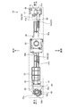
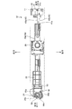
- FIG. 2 is a plan view showing a standby state of the commodity storage device according to the first embodiment of the present invention.
- FIG. 3 is a side view showing a standby state of the commodity storage device according to Embodiment 1 of the present invention.
- FIG. 4 is a bottom view showing a standby state of the product storage device according to the first embodiment of the present invention.
- FIG. 5 is an enlarged side view showing the pressing portion shown in FIG. 3 in an enlarged manner.
- FIG. 6 is an enlarged plan view showing the guide hole shown in FIG. 2 in an enlarged manner.
- FIG. 1 is a schematic diagram schematically showing the internal structure of a vending machine to which the product storage device according to Embodiment 1 of the present invention is applied.
- FIG. 2 is a plan view showing a standby state of the commodity storage device according to the first
- FIG. 7 is a plan view showing an operation state of the commodity storage device according to the first embodiment of the present invention.
- FIG. 8 is a side view showing an operation state of the commodity storage device according to the first embodiment of the present invention.
- FIG. 9 is a bottom view showing an operation state of the product storage device according to the first embodiment of the present invention.
- FIG. 10 is an enlarged plan view showing the guide hole shown in FIG. 7 in an enlarged manner.
- FIG. 11 is a plan view showing an operation state of the commodity storage device according to the first embodiment of the present invention.
- FIG. 12 is a side view showing an operation state of the commodity storage device according to the first embodiment of the present invention.
- FIG. 13 is a bottom view showing an operation state of the product storage device according to the first embodiment of the present invention.
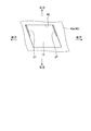
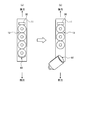
- FIGS. 15A and 15B are schematic diagrams schematically showing the delivery of the foremost product of the product storage device according to the first embodiment of the present invention, where FIG. 15A shows a standby state and FIG. 15B shows an operating state.
- FIG. 16 is a top view which shows the operation state of the goods storage apparatus which is Embodiment 1 of this invention.
- FIG. 17 is a plan view showing a standby state of the commodity storage device according to the second embodiment of the present invention.
- FIG. 18 is a side view showing a standby state of the product storage device according to Embodiment 2 of the present invention.
- FIG. 19 is a bottom view showing a standby state of the product storage device according to Embodiment 2 of the present invention.
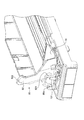
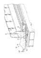
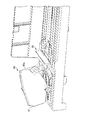
- FIG. 20 is an enlarged perspective view showing a front portion of the product storage device shown in FIGS.
- FIG. 21 is an enlarged perspective view showing a front portion of the product storage device shown in FIGS.
- FIG. 22 is a plan view showing an operating state of the commodity storage device according to the second embodiment of the present invention.
- FIG. 23 is a side view showing an operation state of the commodity storage device according to the second embodiment of the present invention.
- FIG. 24 is a bottom view showing an operation state of the product storage device according to the second embodiment of the present invention.
- FIG. 25 is an enlarged perspective view showing a front portion of the product storage device shown in FIGS.
- FIG. 20 is an enlarged perspective view showing a front portion of the product storage device shown in FIGS.
- FIG. 21 is an enlarged perspective view showing a front portion of the product storage device shown in FIGS.
- FIG. 22 is
- FIG. 26 is an enlarged perspective view of the front portion of the product storage device shown in FIGS.
- FIG. 27 is a plan view showing an operation state of the commodity storage device according to the second embodiment of the present invention.
- FIG. 28 is a side view showing an operation state of the commodity storage device according to the second embodiment of the present invention.
- FIG. 29 is a bottom view showing an operation state of the commodity storage device according to the second embodiment of the present invention.
- FIG. 30 is an enlarged perspective view showing the front portion of the product storage device shown in FIGS.
- FIG. 31 is an enlarged perspective view showing a front portion of the product storage device shown in FIGS.
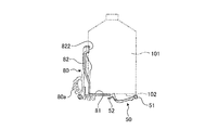
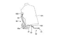
- FIGS. 32A and 32B are schematic diagrams schematically showing the delivery of the foremost product of the product storage device according to the second embodiment of the present invention, where FIG.
- FIG. 33 is an explanatory diagram showing a case where another product is held in the product storage device according to the second embodiment of the present invention.
- FIG. 34 is an explanatory view schematically showing the operation of the assist member.
- FIG. 35 is an explanatory diagram schematically showing the operation of the assist member.
- FIG. 36 is an explanatory view schematically showing the operation of the assist member.
- FIG. 37 is a perspective view showing a modification of the product storage device according to Embodiment 2 of the present invention.
- FIG. 38 is a perspective view showing a modification of the product storage device according to Embodiment 2 of the present invention.
- FIG. 1 is a schematic diagram schematically showing the internal structure of a vending machine to which the product storage device according to Embodiment 1 of the present invention is applied.
- the vending machine illustrated here includes a main body cabinet 1.
- the main body cabinet 1 is a rectangular housing having an open front surface, and a product storage 2 having a heat insulating structure is disposed therein.
- the product rack 2 is provided with a plurality of product racks 3 in the vertical direction. These merchandise racks 3 are configured by providing merchandise storage apparatuses 10 to be described later so as to be arranged side by side.
- the product storage 2 adjusts the product stored in the product rack 3 to a desired temperature by cooling the internal atmosphere by a cooling means (not shown).
- a product tray 4 is disposed so as to be movable in the vertical direction by a transport mechanism (not shown).
- the product tray 4 is provided on a closing member 5 that receives a product delivered from a product storage device 10 that stores a desired product and then moves downward to close the lower side of the front opening of the main body cabinet 1.
- the product is allowed to be taken out from the product take-out port 6.
- the closing member 5 closes the front opening of the main body cabinet 1 together with the door body 7 provided thereabove, and the door body 7 is disposed in the main body cabinet 1 so as to be openable and closable. .
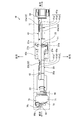
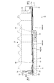
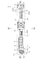
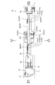
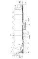
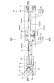
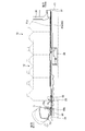
- FIG. 2 to 4 show the standby state of the product storage apparatus 10 according to the first embodiment of the present invention.
- FIG. 2 is a plan view
- FIG. 3 is a side view
- FIG. 4 is a bottom view. 2 to 4, the main components are shown by solid lines, and the other components are shown by two-dot chain lines or omitted.
- the product storage device 10 defines a product storage passage 12 extending along the front-rear direction on the upper surface 11a of the base 11 between side plates (not shown) standing upright and left and right.
- the products are stored in the passage 12 so as to be lined up in a standing posture.
- the standing posture of the product refers to a posture in which the axis of the product extends along the vertical direction with respect to the placement surface 13 (the upper surface 11a of the base 11) of the product storage passage 12.
- the product storage device 10 includes a slider 20, a pusher (pusher member) 30, and a stopper (regulation member) 40.
- a deformed connection hole 21, an engagement pin 22, a pressing portion 23, and a slider engagement portion 24 are formed in a slider base portion 20 a that is a long member whose longitudinal direction is the longitudinal direction in a lower region of the product storage passage 12. Is made up of.
- the odd-shaped connecting hole 21 is formed in a substantially central region of the slider base 20a, has a long hole shape in which the left-right direction is the longitudinal direction, and further includes a central portion of the front edge portion and a central portion of the rear edge portion. Has a shape expanded in the front-rear direction.
- the odd-shaped connecting hole 21 includes an enlarged diameter hole 21a, a right side hole 21b continuous to the right of the enlarged diameter hole 21a, and a left side hole 21c continuous to the left of the enlarged diameter hole 21a. Has been.
- the transmission pin 25 is inserted into the deformed connection hole 21 from below.
- the transmission pin 25 transmits the driving force of the motor 26 provided in the lower area of the slider 20 to the slider 20, and is erected in the vicinity of the periphery of the disk-shaped transmission plate 25a.
- the transmission plate 25a rotates about its own center when the motor 26 is driven.
- a plurality of engagement pins 22 are provided, and are provided at a position ahead of the rear end portion of the slider base 20a and the deformed connection hole 21 in the central region of the slider base 20a.
- the joint pin (hereinafter also referred to as a second engagement pin) 22b protrudes upward from the slider base 20a.
- the pressing part 23 is formed at the front end of the slider base 20a. As shown in an enlarged view in FIG. 5, the pressing portion 23 has an inclined portion 23a that gradually inclines upward toward the rear surface on the upper surface 11a. An assist member 50 is provided above the pressing portion 23.
- the assist member 50 is rotatable about the axis of the assist shaft portion 51 by the assist shaft portion 51 formed at the rear end portion being pivotally supported by the base 11.
- the assist member 50 has a shape that curves upward as the tip end side of the assist shaft portion 51 moves forward, and a protruding piece 52 that protrudes forward is formed at the tip portion.
- the assist member 50 is formed with an assist protrusion 53 that protrudes downward from the lower surface on the front side of the assist shaft portion 51.
- Such an assist member 50 is provided so as to be swingable in such a manner that it moves forward and backward to the product storage passage 12 through an assist opening 14 formed in the mounting surface 13 of the product storage passage 12. In the standby state as shown, the product is retracted from the product storage passage 12.
- the slider engagement portion 24 is a long portion that is formed in the forefront of the slider base portion 20a and extends forward from the right side of the front end surface of the pressing portion 23.
- a slider gear 24 a is provided at the front left end portion of the slider meshing portion 24.
- a part of the slider gear 24 a of the slider meshing portion 24 meshes with a transmission gear 60 a provided on a part of the outer peripheral surface of a disk-shaped transmission member 60 that is rotatably provided in a lower region of the product storage passage 12.
- a communication gear 60b is formed at a location different from the location where the transmission gear 60a is formed on the outer peripheral surface of the transmission member 60.
- the communication gear 60 b meshes with the holder gear 70 a of the holder 70.
- the holder 70 is provided in the front area of the upper surface 11 a of the base 11 constituting the product storage passage 12, and itself constitutes the product storage passage 12.
- the holder 70 has a flat plate-like placement portion 71 and a curved support portion 72 that extends upward from the front end portion of the placement portion 71.
- the mounting portion 71 is provided at a level substantially the same as the mounting surface 13 of the product storage passage 12, and in a standby state as shown in FIGS.
- the device itself is also in a standing posture, and holds the product in a standing posture on the mounting portion 71.
- the holder gear 70 a is disposed in a substantially spiral shape on the outer surface of the support portion 72 of the holder 70.
- the pusher 30 is provided in the product storage passage 12. More specifically, the pusher 30 is provided in the product storage passage 12 in such a manner as to penetrate a groove (not shown) formed in the upper surface 11 a of the base 11 along the front-rear direction. Yes.
- the pusher 30 is always urged forward by an urging means (not shown) such as a constant load spring, and presses the product stored in the product storage passage 12 forward.
- a pusher meshing portion 31 is provided at a lower portion of the pusher 30, that is, in a lower region of the product storage passage 12.
- a pusher gear 31a is formed on the left side of the pusher meshing portion 31.
- the stopper 40 is formed in the lower portion of the product storage passage 12 and the upper portion of the slider 20 in the stopper base portion 40a which is a long member whose longitudinal direction is the longitudinal direction.
- a portion (regulation meshing portion) 43 is formed.
- a plurality of (two in the illustrated example) engagement holes 41 are provided, and are provided at the rear end portion of the stopper base portion 40a and the front end portion of the stopper base portion 40a.
- 41b both having the same shape, and inclined in the left direction from the front ends of the first long hole portions 41a1 and 41b1 and the first long hole portions 41a1 and 41b1 whose longitudinal direction is the longitudinal direction.
- Inclined hole portions 41a2 and 41b2 and second long hole portions 41a3 and 41b3 extending forward from the front ends of the inclined hole portions 41a2 and 41b2 are continuously formed.
- the first engagement pin 22a is inserted through the first engagement hole 41a, and the second engagement pin 22b is inserted through the second engagement hole 41b.
- the first engagement pin 22a is inserted through the front end position of the first long hole portion 41a1 of the first engagement hole 41a, and the second engagement pin 22b passes through the front end position of the first long hole portion 41b1 of the second engagement hole 41b.
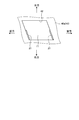
- the guide hole 42 is provided in front of the second engagement hole 41b of the stopper base 40a and has a parallelogram shape. As shown in an enlarged view in FIG. 6, two guide protrusions 27 provided on the base 11 are inserted into the guide hole 42. These two guide projections 27 are inserted into the front edge portion and the rear edge portion of the guide hole 42 so as to be slidable. The guide protrusions 27 are in contact with the right edge of the guide hole 42 in the standby state as shown in FIGS.
- the inclination angle of the guide hole 42 is substantially the same as the inclination angles of the inclined hole portions 41a2 and 41b2 of the first engagement hole 41a and the second engagement hole 41b.
- the stopper meshing portion 43 is provided at the right end portion of the stopper base portion 40a over the entire length of the stopper base portion 40a, and is configured by a stopper gear 43a provided at the right end portion of the stopper base portion 40a. In the standby state as shown in FIGS. 2 to 4, the stopper meshing portion 43 is separated from the pusher meshing portion 31, and the stopper gear 43a and the pusher gear 31a are not meshed. That is, the stopper meshing portion 43 is not meshed with the pusher meshing portion 31.
- the product storage device 10 having the above-described configuration operates as follows when a drive command (payout command) is given in a state where the product tray 4 is arranged in the front area of the product storage passage 12.
- the first engagement pin 22a of the slider 20 moves the first engagement hole 41a to move the inclined hole 41a2 from the first long hole 41a1.
- the second engagement pin 22b passes through the inclined hole portion 41b2 from the first long hole portion 41b1 by moving through the second engagement hole 41b by passing through the inclined hole portion 41b2 to the front end position of the inclined hole portion 41a2. It reaches the front end position of 41b2.
- the stopper 40 is displaced diagonally rightward in accordance with the inclination of the inclined hole portions 41a2 and 41b2.
- the guide protrusion 27 of the base 11 is displaced relatively diagonally leftward while slidingly contacting the front edge portion and the rear edge portion of the guide hole 42.
- the stopper 40 is displaced diagonally to the left and left, the stopper meshing portion 43 comes close to the pusher meshing portion 31, and the stopper gear 43a meshes with the pusher gear 31a.
- the pusher 30 is restricted from moving forward by being urged by the urging means, and as a result, the pusher 30 is restricted from pushing forward against the product.
- the slider meshing portion 24 slides forward, whereby the transmission member 60 that engages the slider gear 24a and the transmission gear 60a rotates clockwise in FIG. .
- the transmission member 60 rotates clockwise
- the foremost product held by the holder 70 also has an inclined posture in which the axis is inclined to the left and right.
- the assist member 50 has an assist shaft portion. Oscillating upward about the axis of 51, the tip portion advances into the product storage passage 12 through the assist opening 14.
- the assist member 50 assists in the attitude change of the product by the holder 70 when the outer end of the product held in the holder 70 (the foremost product) has a large outer diameter abuts against the bottom surface of the product. To do.
- the transmission pin 25 When the transmission pin 25 enters the enlarged diameter hole 21a from the right side hole 21b of the deformed connection hole 21 by driving the motor 26 and presses the front edge part of the enlarged diameter hole 21a, the transmission pin 25 is shown in FIGS. As shown, the slider 20 slides further forward.
- the first engagement pin 22a of the slider 20 moves from the inclined hole portion 41a2 to the second long hole portion 41a3 by moving the first engagement hole 41a.
- the second engagement pin 22b moves from the inclined hole portion 41b2 to the second long hole portion 41b3 by moving the second engagement hole 41b. It reaches the front end position of the second long hole portion 41b3.
- the stopper 40 is further displaced obliquely rearward to the right according to the inclination of the inclined hole portions 41a2 and 41b2.
- the guide protrusion 27 of the slider 20 is further displaced relatively obliquely left forward while slidingly contacting the front edge portion and the rear edge portion of the guide hole 42.
- the stopper 40 is further displaced diagonally to the left and left, so that the stopper meshing portion 43 comes closer to the pusher meshing portion 31 and the meshing state in which the stopper gear 43a meshes with the pusher gear 31a is more firmly maintained.
- the slider meshing portion 24 slides forward, whereby the transmission member 60 in which the slider gear 24a meshes with the transmission gear 60a further rotates clockwise in FIG. Rotate.
- the transmission member 60 further rotates in this way, the holder 70 in which the communication gear 60b of the transmission member 60 and the holder gear 70a mesh with each other rotates according to the arrangement form of the holder gear 70a, and is further inclined toward the left front side. Become posture. As a result, the foremost product held in the holder 70 is paid out to the front area in an inclined posture in which its own axis is inclined leftward.
- the product delivered to the front area in this way is received in the product tray 4, moves downward together with the product tray 4, and is then taken out through the product outlet 6.
- the transmission pin 25 enters the left hole 21c from the enlarged diameter hole 21a of the deformed connection hole 21 and presses the rear edge of the left hole 21c, as shown in FIG.
- the slider 20 slides backward.
- the first engagement pin 22a of the slider 20 moves through the first engagement hole 41a and passes through the second long hole portion 41a3 to be second.
- the second engagement pin 22b reaches the rear end position of the long hole portion 41a3, and moves through the second engagement hole 41b so as to pass through the second long hole portion 41b3 and the rear end position of the second long hole portion 41b3.
- the slider meshing portion 24 slides rearward, whereby the transmission member 60 in which the slider gear 24a meshes with the transmission gear 60a rotates counterclockwise in FIG. To do.
- the transmission member 60 rotates in this way, the holder 70 in which the communication gear 60b of the transmission member 60 and the holder gear 70a mesh with each other is rotated obliquely rearward to the right according to the arrangement form of the holder gear 70a.
- the assist member 50 that contacts the pressing portion 23 swings downward around the axis of the assist shaft portion 51, and the tip portion passes through the assist opening 14.
- the assist member 50 that contacts the pressing portion 23 swings downward around the axis of the assist shaft portion 51, and the tip portion passes through the assist opening 14.
- the first engagement pin 22a passes through the inclined hole portion 41a2 of the first engagement hole 41a, and the second engagement pin 22b passes through the second engagement hole 41b.
- the stopper 40 is displaced forward and diagonally left in accordance with the inclination of the inclined hole portions 41a2 and 41b2.
- the stopper meshing portion 43 is separated from the pusher meshing portion 31 so that they are not meshed.
- the pusher 30 presses the product forward by the urging force of the urging means.
- the product adjacent to the rear of the delivered product is held in the holder 70 as the foremost product.
- the slider 20, the transmission member 60, and the holder 70 are centered on the product (the most downstream product) as the axis when the payout command is given.
- Commodity payout means for paying out in an inclined posture inclined left and right with respect to the extending direction of the storage passage 12 is configured.
- the front and rear length of the front area of the product storage passage 12 can be made sufficiently small, Goods can be paid out satisfactorily while suppressing an increase in installation space and a reduction in the number of goods stored.
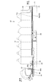
- FIGS. 17 to 19 show the standby state of the product storage device according to the second embodiment of the present invention.
- FIG. 17 is a plan view
- FIG. 18 is a side view
- components having the same configuration as those of the product storage device of the first embodiment described above are denoted by the same reference numerals, and description thereof is omitted as appropriate.
- the product storage device 10 ′ illustrated here is different from the product storage device 10 in that it has a holder 80 instead of the holder 70 in the product storage device 10, and includes a slider 20, a pusher (pusher member) 30, The stopper (regulating member) 40, the assist member 50, the transmission member 60, and the like have the same configuration.
- the holder 80 is provided in the front area of the upper surface 11a of the base 11 constituting the product storage passage 12, and itself constitutes the product storage passage 12.
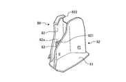
- the holder 80 has a flat plate-like placement portion 81 and a curved support portion 82 extending upward from the front end portion of the placement portion 81.
- the mounting portion 81 is provided at a level substantially the same as the mounting surface 13 of the product storage passage 12, and in the standby state as shown in FIGS.
- the self is also in a standing posture, and holds the product in a standing posture on the mounting portion 81.
- the holder gear 80 a is disposed in a substantially spiral shape on the outer surface of the support portion 82 of the holder 80.
- the holder gear 80a meshes with the communication gear 60b of the transmission member 60.
- a through hole (hole) 821 is formed in the support portion 82 of such a holder 80.
- the through hole 821 is formed slightly to the right in the lower region of the support portion 82.
- the through-hole 821 is to be penetrated by a protrusion 131 provided so as to protrude upward from the placement surface 13 when the holder 80 is tilted.
- the protrusion 131 is formed such that the protrusion height with respect to the support portion 82 when passing through the through hole 821 is large enough to move the center of gravity of the product held in the holder 80. Yes.
- a contact portion 822 is formed on the support portion 82 of the holder 80.
- the contact portion 822 is formed by bending the upper end portion of the support portion 82 toward the rear, and is formed so as to protrude about 3 to 7 mm toward the rear, for example.
- the abutting portion 822 is formed at a height at which the abutting portion 822 can abut on the central portion of the product, that is, the trunk portion 101.
- the product storage device 10 ′ having the above-described configuration operates as follows when a drive command (payout command) is given in a state where the product tray 4 is disposed in the front area of the product storage passage 12.
- the transmission pin 25 that rotates clockwise in FIG. 17 around the central portion of the transmission plate 25 a enters the right hole portion 21 b from the enlarged diameter hole portion 21 a of the deformed connection hole 21, and enters the right hole portion. Press the front edge of 21b. As a result, as shown in FIGS. 22 to 24, the slider 20 slides forward.
- the first engagement pin 22a of the slider 20 moves the first engagement hole 41a to move the inclined hole 41a2 from the first long hole 41a1.
- the second engagement pin 22b passes through the inclined hole portion 41b2 from the first long hole portion 41b1 by moving through the second engagement hole 41b by passing through the inclined hole portion 41b2 to the front end position of the inclined hole portion 41a2. It reaches the front end position of 41b2.
- the stopper 40 is displaced diagonally rightward in accordance with the inclination of the inclined hole portions 41a2 and 41b2.
- the guide protrusion 27 of the base 11 is displaced relatively diagonally left forward while being in sliding contact with the front edge portion and the rear edge portion of the guide hole 42.
- the stopper 40 is displaced diagonally to the left and left, the stopper meshing portion 43 comes close to the pusher meshing portion 31, and the stopper gear 43a meshes with the pusher gear 31a.
- the pusher 30 is restricted from moving forward by being urged by the urging means, and as a result, the pusher 30 is restricted from pushing forward against the product.
- the slider 20 slides forward, the slider meshing portion 24 slides forward, whereby the transmission member 60 that engages the slider gear 24a and the transmission gear 60a rotates clockwise in FIG. .
- the transmission member 60 rotates clockwise as described above, the holder 80 in which the communication gear 60b of the transmission member 60 and the holder gear 80a mesh with each other is rotated according to the arrangement form of the holder gear 80a as shown in FIGS. It moves and becomes a slightly inclined posture toward the left front side.
- the foremost product held by the holder 80 also has a posture in which the axis is inclined to the left and right.
- the protrusion 131 does not reach the through hole 821 when the holder 80 is in a slightly inclined posture.
- the assist member 50 has an assist shaft portion. Oscillating upward about the axis of 51, the tip portion advances into the product storage passage 12 through the assist opening 14.
- the transmission pin 25 enters the enlarged diameter hole 21a from the right side hole 21b of the deformed connection hole 21 and presses the front edge of the enlarged diameter hole 21a. As shown, the slider 20 slides further forward.
- the first engagement pin 22a of the slider 20 moves from the inclined hole portion 41a2 to the second long hole portion 41a3 by moving the first engagement hole 41a.
- the second engagement pin 22b moves from the inclined hole portion 41b2 to the second long hole portion 41b3 by moving the second engagement hole 41b. It reaches the front end position of the second long hole portion 41b3.
- the stopper 40 is further displaced obliquely rearward to the right according to the inclination of the inclined hole portions 41a2 and 41b2.
- the guide protrusions 27 of the base 11 are further displaced obliquely forward and to the left while slidingly contacting the front edge portion and the rear edge portion of the guide hole 42.
- the stopper 40 is further displaced diagonally to the left and left, so that the stopper meshing portion 43 comes closer to the pusher meshing portion 31 and the meshing state in which the stopper gear 43a meshes with the pusher gear 31a is more firmly maintained.
- the slider meshing portion 24 slides forward, whereby the transmission member 60 in which the slider gear 24a meshes with the transmission gear 60a is counterclockwise in FIG. It rotates further.
- the transmission member 60 further rotates as described above, the holder 80 in which the connecting gear 60b of the transmission member 60 and the holder gear 80a mesh with each other rotates according to the arrangement of the holder gear 80a as shown in FIGS.
- the tilted posture is more inclined toward the left front side.
- the protrusion 131 formed on the mounting surface 13 passes through the through hole 821 and protrudes upward from the support portion 82 as shown in FIGS. It will be in the state. Therefore, the most recent product held in the holder 80 is brought into contact with the protrusion 131 that penetrates the through hole 821 while the axis of the holder 80 is tilted to the left by the tilting posture of the holder 80. The center of gravity moves and is paid out to the front area.
- the most recent product held in the standing posture holder 80 in the standing posture is the receiving posture of the holder 80 as shown in FIG.
- its own axis is inclined to the left and right, and is paid out to the front area.
- the product delivered to the front area in this way is received in the product tray 4, moves downward together with the product tray 4, and is then taken out through the product outlet 6.
- the transmission pin 25 enters the left hole 21c from the enlarged diameter hole 21a of the deformed connection hole 21 and presses the rear edge of the left hole 21c, so that the slider 20 faces rearward. Move the slide.
- the first engagement pin 22a of the slider 20 moves through the first engagement hole 41a and passes through the second long hole portion 41a3 to be second.
- the second engagement pin 22b reaches the rear end position of the long hole portion 41a3, and moves through the second engagement hole 41b so as to pass through the second long hole portion 41b3 and the rear end position of the second long hole portion 41b3.
- the slider meshing portion 24 slides rearward, whereby the transmission member 60 that engages the slider gear 24a and the transmission gear 60a rotates clockwise in FIG. .
- the holder 80 in which the communication gear 60b of the transmission member 60 and the holder gear 80a mesh with each other is rotated toward the right rear in accordance with the arrangement form of the holder gear 80a.
- the assist member 50 that contacts the pressing portion 23 swings downward around the axis of the assist shaft portion 51, and the tip portion passes through the assist opening 14.
- the assist member 50 that contacts the pressing portion 23 swings downward around the axis of the assist shaft portion 51, and the tip portion passes through the assist opening 14.
- the first engagement pin 22a passes through the inclined hole portion 41a2 of the first engagement hole 41a, and the second engagement pin 22b passes through the second engagement hole 41b.
- the stopper 40 is displaced forward and diagonally left in accordance with the inclination of the inclined hole portions 41a2 and 41b2.
- the stopper meshing portion 43 is separated from the pusher meshing portion 31 so that they are not meshed.
- the pusher 30 presses the product forward by the urging force of the urging means.
- the product adjacent to the rear of the paid-out product is received by the holder 80 in the receiving posture as the foremost product.
- the contact portion 822 formed on the support portion 82 of the holder 80 comes into contact with the body portion 101 of the product.
- the slider 20, the transmission member 60, the assist member 50, and the holder 80 receive the most recent product (the most downstream product) when a payout command is given.
- the most recent product the most downstream product
- the protrusion 131 and the through hole 821 constitute a product delivery assisting unit that assists the delivery of the most downstream product by the product delivery unit by moving the center of gravity of the most downstream product that is inclined by the product delivery unit. .
- the front-rear length of the front area of the goods storage passage 12 can be made sufficiently small. Thereby, goods can be paid out favorably, suppressing the enlargement of an installation space and the fall of the storage number of goods.
- the protrusion 131 formed on the placement surface 13 passes through the through-hole 821 of the holder 80 and comes into contact with the tilted product to move the center of gravity of the product. Therefore, even if the product has a shape that is difficult to be paid out only when the holder 80 is tilted, the protrusion 131 comes into contact with the product to move the center of gravity of the product, so that the balance of the product is lost. , The product can be paid out satisfactorily.
- the contact portion 822 formed on the support portion 82 of the holder 80 contacts the body 101 of the product when the holder 80 receives the product in the receiving posture. It can suppress that the goods pressed by the pusher 30 ahead and received by the holder 80 incline toward the front by contacting a part of the holder 80.
- the contact portion 822 has the By coming into contact with the body portion 101, the product can be prevented from inclining forward, and the product can be prevented from falling forward.
- the assist member 50 that retreats from the product storage passage 12 when the holder 80 is in the receiving posture is moved to the product storage passage 12 when the holder 80 is tilted from the receiving posture.
- the tip portion that moves forward contacts the bottom surface 102 of the product Assist the deformation of the product posture by the holder 80.
- the assist member 50 is received and held by the holder 80.
- the product stored in the product storage passage 12 is pressed by the pusher 30, but in the present invention, as the product storage passage heads forward. May be gradually inclined downward. According to this, the pressing force by the pusher can be weakened, and further, it can be moved forward by the weight of the product without using the pusher.
- attachment members 91 and 92 may be attached to the holder 80 to reduce the product placing area in the placing portion 81.
- the attachment members 91 and 92 members having various shapes can be used as appropriate.
- the end portions 91a and 92a of the portion extending forward pass through the locking holes 83 of the holder 80. And is attached by a so-called snap fit that is locked to the holder 80.
- the mountable area of the mounting portion 81 of the holder 80 can be reduced, so that products with extremely small cross-sectional areas can be received and dispensed one by one. Can do.
- the protrusion 131 and the through hole 821 move the center of gravity of the most downstream product that is inclined by the product dispensing means, thereby assisting the dispensing of the most downstream commodity by the commodity dispensing means.
- the form is not particularly limited as long as the center of gravity of the product can be moved. That is, it may be one that gives vibration to the product in the tilted posture, or may press the bottom surface of the product in the tilted posture.
Landscapes
- Physics & Mathematics (AREA)
- General Physics & Mathematics (AREA)
- Vending Machines For Individual Products (AREA)
- De-Stacking Of Articles (AREA)
- Control Of Vending Devices And Auxiliary Devices For Vending Devices (AREA)
Abstract
Description
図1は、本発明の実施の形態1である商品収納装置が適用された自動販売機の内部構造を模式的に示す模式図である。ここで例示する自動販売機は、本体キャビネット1を備えて構成してある。
図17~図19は、それぞれ本発明の実施の形態2である商品収納装置の待機状態を示すもので、図17は平面図、図18は側面図、図19は底面図である。これら図17~図19では、主要な構成要素を実線で示し、その他の構成要素については二点鎖線で示したり、省略したりしている。尚、以下においては、上述した実施の形態1の商品収納装置と同一の構成を有するものについては同一の符号を付してその説明を適宜省略する。
2 商品収容庫
3 商品ラック
10 商品収納装置
10′ 商品収納装置
12 商品収納通路
13 載置面
131 突部
14 アシスト開口
20 スライダ
20a スライダ基部
21 異形連結孔
21a 拡径孔部
21b 右側孔部
21c 左側孔部
22 係合ピン
22a 第1係合ピン
22b 第2係合ピン
23 押圧部
24 スライダ噛合部
24a スライダギア
25 伝達ピン
26 モータ
27 ガイド突起
30 プッシャ(プッシャ部材)
31 プッシャ噛合部
31a プッシャギア
40 ストッパ(規制部材)
40a ストッパ基部
41 係合孔
41a 第1係合孔
41a1 第1長孔部
41a2 傾斜孔部
41a3 第2長孔部
41b 第2係合孔
41b1 第1長孔部
41b2 傾斜孔部
41b3 第2長孔部
42 ガイド孔
43 ストッパ噛合部(規制噛合部)
43a ストッパギア
50 アシスト部材
51 アシスト軸部
60 伝達部材
60a 伝達ギア
60b 連絡ギア
70 ホルダ
70a ホルダギア
71 載置部
72 支持部
80 ホルダ
80a ホルダギア
81 載置部
82 支持部
821 貫通孔(孔部)
822 当接部
91 アタッチメント部材
92 アタッチメント部材
101 胴部
102 底面
Claims (11)
- 自身が画成した商品収納通路に該商品収納通路の載置面に対して軸心が垂直方向に沿って延在する態様で商品を起立姿勢にて一列に並ぶよう収納し、払出指令が与えられた場合に前記商品収納通路における最も下流側に位置する最下流商品を払い出すようにした商品収納装置において、
前記払出指令が与えられた場合に、前記最下流商品を前記軸心が前記商品収納通路の延在方向に対して左右に傾斜した傾斜姿勢で払い出す商品払出手段を備えたことを特徴とする商品収納装置。 - 前記商品払出手段は、常態においては前記最下流商品を起立姿勢で保持する一方、前記払出指令が与えられた場合に自身の軸心回りに回転して前記最下流商品を前記傾斜姿勢で払い出すホルダを備えたことを特徴とする請求項1に記載の商品収納装置。
- 前記商品払出手段により傾斜姿勢となる最下流商品の重心を移動させることで該商品払出手段による最下流商品の払い出しを補助する商品払出補助手段を備えたことを特徴とする請求項1に記載の商品収納装置。
- 前記商品払出手段は、常態においては受容姿勢となって前記最下流商品を起立姿勢で受容して保持する一方、前記払出指令が与えられた場合に自身の軸心回りに回転して傾倒姿勢となって前記最下流商品を前記傾斜姿勢で払い出すホルダを備え、
前記商品払出補助手段は、前記商品収納通路の載置面より上方に向けて突出する態様で設けられ、かつ前記ホルダが傾倒姿勢となる場合に該ホルダに形成された孔部を貫通して傾斜姿勢となる最下流商品に当接して該最下流商品の重心を移動させる突部を備えたことを特徴とする請求項3に記載の商品収納装置。 - 前記ホルダは、前記商品収納通路の上流側に向けて突出する態様で設けられ、かつ前記受容姿勢となって前記最下流商品を受容する場合に該最下流商品の胴部に当接する当接部を備えたことを特徴とする請求項4に記載の商品収納装置。
- 前記商品払出手段は、前記商品収納通路に進退移動する態様で揺動可能に配設され、かつ前記ホルダが前記受容姿勢にある場合には前記商品収納通路から退避移動する一方、前記ホルダが前記受容姿勢から前記傾倒姿勢となる場合には前記商品収納通路に進出移動して前記最下流商品に当接して前記ホルダによる最下流商品の姿勢変形をアシストするアシスト部材を備えたことを特徴とする請求項4又は請求項5に記載の商品収納装置。
- 前記商品払出手段は、常態においては受容姿勢となって前記最下流商品を起立姿勢で受容して保持する一方、前記払出指令が与えられた場合に自身の軸心回りに回転して傾倒姿勢となって前記最下流商品を前記傾斜姿勢で払い出すホルダを備えてなり、
前記ホルダは、前記商品収納通路の上流側に向けて突出する態様で設けられ、かつ前記受容姿勢となって前記最下流商品を受容する場合に該最下流商品の胴部に当接する当接部を備えたことを特徴とする請求項3に記載の商品収納装置。 - 前記商品払出手段は、常態においては受容姿勢となって前記最下流商品を起立姿勢で受容して保持する一方、前記払出指令が与えられた場合に自身の軸心回りに回転して傾倒姿勢となって前記最下流商品を前記傾斜姿勢で払い出すホルダと、
前記商品収納通路に進退移動する態様で揺動可能に配設され、かつ前記ホルダが前記受容姿勢にある場合には前記商品収納通路から退避移動する一方、前記ホルダが前記受容姿勢から前記傾倒姿勢となる場合には前記商品収納通路に進出移動して前記最下流商品に当接して前記ホルダによる最下流商品の姿勢変形をアシストするアシスト部材と
を備えたことを特徴とする請求項3に記載の商品収納装置。 - 前記商品収納通路毎に設けられ、かつ付勢手段により下流に向けて常時付勢されることで該商品収納通路に収納される商品を下流側に向けて押圧するプッシャ部材を備えたことを特徴とする請求項1~8のいずれか一つに記載の商品収納装置。
- 常態においては、前記プッシャ部材による商品の押圧を許容する一方、前記商品払出手段により前記最下流商品の払い出しが行われている場合には、前記プッシャ部材による商品の押圧を規制する規制部材を備えたことを特徴とする請求項9に記載の商品収納装置。
- 前記規制部材は、常態においては、自身の規制噛合部が前記プッシャ部材のプッシャ噛合部と離隔して非噛合状態となることで前記プッシャ部材による商品の押圧を許容する一方、前記商品払出手段により前記最下流商品の払い出しが行われている場合には、前記規制噛合部が前記プッシャ噛合部に近接して噛合状態となることにより前記プッシャ部材による商品の押圧を規制することを特徴とする請求項10に記載の商品収納装置。
Priority Applications (3)
| Application Number | Priority Date | Filing Date | Title |
|---|---|---|---|
| JP2014538018A JP5794392B2 (ja) | 2013-08-09 | 2014-03-03 | 商品収納装置 |
| CN201480000812.4A CN104541309B (zh) | 2013-08-09 | 2014-03-03 | 商品收纳装置 |
| KR1020147024513A KR101620251B1 (ko) | 2013-08-09 | 2014-03-03 | 상품 수납 장치 |
Applications Claiming Priority (4)
| Application Number | Priority Date | Filing Date | Title |
|---|---|---|---|
| JP2013166664 | 2013-08-09 | ||
| JP2013-166664 | 2013-08-09 | ||
| JP2013-240356 | 2013-11-20 | ||
| JP2013240356 | 2013-11-20 |
Publications (1)
| Publication Number | Publication Date |
|---|---|
| WO2015019645A1 true WO2015019645A1 (ja) | 2015-02-12 |
Family
ID=52460994
Family Applications (1)
| Application Number | Title | Priority Date | Filing Date |
|---|---|---|---|
| PCT/JP2014/055333 Ceased WO2015019645A1 (ja) | 2013-08-09 | 2014-03-03 | 商品収納装置 |
Country Status (4)
| Country | Link |
|---|---|
| JP (1) | JP5794392B2 (ja) |
| KR (1) | KR101620251B1 (ja) |
| CN (1) | CN104541309B (ja) |
| WO (1) | WO2015019645A1 (ja) |
Families Citing this family (4)
| Publication number | Priority date | Publication date | Assignee | Title |
|---|---|---|---|---|
| JP6459560B2 (ja) * | 2015-01-28 | 2019-01-30 | 富士電機株式会社 | 商品収納装置 |
| CN107710289B (zh) * | 2015-08-04 | 2020-05-08 | 富士电机株式会社 | 商品收纳装置和自动售货机 |
| JP7020544B2 (ja) * | 2018-04-27 | 2022-02-16 | 富士電機株式会社 | 商品収納ラック及び商品収納装置 |
| JP7571490B2 (ja) * | 2020-11-17 | 2024-10-23 | 富士電機株式会社 | 商品収納装置及び商品載置棚 |
Citations (4)
| Publication number | Priority date | Publication date | Assignee | Title |
|---|---|---|---|---|
| JP2003077044A (ja) * | 2001-09-05 | 2003-03-14 | Kubota Corp | 自動販売機 |
| US20060169714A1 (en) * | 2003-09-26 | 2006-08-03 | Holdway John B | Clear door vending machine |
| JP2009003924A (ja) * | 2007-05-21 | 2009-01-08 | Sanden Corp | 商品搬出装置 |
| EP2363841A1 (en) * | 2010-03-04 | 2011-09-07 | Automated Retail Concepts B.V. | Product dispensing machine and dispensing method |
Family Cites Families (8)
| Publication number | Priority date | Publication date | Assignee | Title |
|---|---|---|---|---|
| DE1115977B (de) * | 1958-07-03 | 1961-10-26 | Georg Wiegandt & Soehne | Selbstverkaeufer fuer hochformatige Waren |
| US3512679A (en) * | 1968-06-05 | 1970-05-19 | James P Stoltz | Multi-selection dispensing machine |
| JPH09106479A (ja) * | 1995-04-24 | 1997-04-22 | Maachiyandaijingu Manag:Kk | 自動販売機 |
| JP3478066B2 (ja) * | 1997-06-02 | 2003-12-10 | 富士電機ホールディングス株式会社 | 自動販売機の商品収納装置 |
| JP2002008121A (ja) * | 2000-06-16 | 2002-01-11 | Shinji Abe | 自動販売機用商品送出装置 |
| US20030150870A1 (en) * | 2002-02-13 | 2003-08-14 | Allan Gilbert | Universal vending machine |
| JP2004318829A (ja) | 2003-03-28 | 2004-11-11 | Sanden Corp | 自動販売機 |
| EP2390849B1 (en) * | 2007-05-16 | 2014-07-30 | Sanden Corporation | Commodity carrying out device |
-
2014
- 2014-03-03 KR KR1020147024513A patent/KR101620251B1/ko not_active Expired - Fee Related
- 2014-03-03 JP JP2014538018A patent/JP5794392B2/ja not_active Expired - Fee Related
- 2014-03-03 WO PCT/JP2014/055333 patent/WO2015019645A1/ja not_active Ceased
- 2014-03-03 CN CN201480000812.4A patent/CN104541309B/zh not_active Expired - Fee Related
Patent Citations (4)
| Publication number | Priority date | Publication date | Assignee | Title |
|---|---|---|---|---|
| JP2003077044A (ja) * | 2001-09-05 | 2003-03-14 | Kubota Corp | 自動販売機 |
| US20060169714A1 (en) * | 2003-09-26 | 2006-08-03 | Holdway John B | Clear door vending machine |
| JP2009003924A (ja) * | 2007-05-21 | 2009-01-08 | Sanden Corp | 商品搬出装置 |
| EP2363841A1 (en) * | 2010-03-04 | 2011-09-07 | Automated Retail Concepts B.V. | Product dispensing machine and dispensing method |
Also Published As
| Publication number | Publication date |
|---|---|
| JP5794392B2 (ja) | 2015-10-14 |
| KR20150037726A (ko) | 2015-04-08 |
| CN104541309A (zh) | 2015-04-22 |
| CN104541309B (zh) | 2017-05-03 |
| JPWO2015019645A1 (ja) | 2017-03-02 |
| KR101620251B1 (ko) | 2016-05-12 |
Similar Documents
| Publication | Publication Date | Title |
|---|---|---|
| JP5742397B2 (ja) | 自動販売機 | |
| JP5794392B2 (ja) | 商品収納装置 | |
| JP5659745B2 (ja) | 自動販売機 | |
| JP7043926B2 (ja) | 自動販売機 | |
| JP4888234B2 (ja) | 自動販売機の商品収納装置 | |
| CN105279853B (zh) | 杯装饮料提供装置的杯供给装置 | |
| CN102682528B (zh) | 自动售货机的商品搬出装置 | |
| JP5277759B2 (ja) | 自動販売機の商品搬出装置 | |
| JP4101093B2 (ja) | 自動販売機の商品収納装置 | |
| JP4124347B2 (ja) | 自動販売機の商品搬出装置 | |
| JP2012118899A (ja) | 自動販売機 | |
| JP5949011B2 (ja) | 自動販売機の商品搬出装置 | |
| JP2023039677A (ja) | 商品収納装置 | |
| JP4539508B2 (ja) | 商品搬出装置 | |
| JP5359205B2 (ja) | 商品収納装置 | |
| JP2022177513A (ja) | 商品収納ラック及び商品収納装置 | |
| JP2002358568A (ja) | 自動販売機の商品収納払出し装置 | |
| JP6834466B2 (ja) | 自動販売機の商品搬出装置 | |
| JP6638279B2 (ja) | 自動販売機 | |
| JP2003228757A (ja) | 自動販売機のサーペンタイン式商品収納ラック | |
| JP3826514B2 (ja) | 自動販売機の商品収納払出装置 | |
| JP4389807B2 (ja) | 自動販売機の商品収納払出し装置 | |
| JP2004178112A (ja) | 自動販売機の扉閉鎖装置 | |
| CN110120122A (zh) | 自动售货机 | |
| JP2010257016A (ja) | 自動販売機の商品搬出装置 |
Legal Events
| Date | Code | Title | Description |
|---|---|---|---|
| ENP | Entry into the national phase |
Ref document number: 2014538018 Country of ref document: JP Kind code of ref document: A |
|
| ENP | Entry into the national phase |
Ref document number: 20147024513 Country of ref document: KR Kind code of ref document: A |
|
| 121 | Ep: the epo has been informed by wipo that ep was designated in this application |
Ref document number: 14834206 Country of ref document: EP Kind code of ref document: A1 |
|
| NENP | Non-entry into the national phase |
Ref country code: DE |
|
| 122 | Ep: pct application non-entry in european phase |
Ref document number: 14834206 Country of ref document: EP Kind code of ref document: A1 |