WO2015016151A1 - 眼科撮像装置及びその制御方法 - Google Patents
眼科撮像装置及びその制御方法 Download PDFInfo
- Publication number
- WO2015016151A1 WO2015016151A1 PCT/JP2014/069720 JP2014069720W WO2015016151A1 WO 2015016151 A1 WO2015016151 A1 WO 2015016151A1 JP 2014069720 W JP2014069720 W JP 2014069720W WO 2015016151 A1 WO2015016151 A1 WO 2015016151A1
- Authority
- WO
- WIPO (PCT)
- Prior art keywords
- eye
- imaging
- anterior
- illumination
- unit
- Prior art date
- Legal status (The legal status is an assumption and is not a legal conclusion. Google has not performed a legal analysis and makes no representation as to the accuracy of the status listed.)
- Ceased
Links
Images



Classifications
-
- A—HUMAN NECESSITIES
- A61—MEDICAL OR VETERINARY SCIENCE; HYGIENE
- A61B—DIAGNOSIS; SURGERY; IDENTIFICATION
- A61B3/00—Apparatus for testing the eyes; Instruments for examining the eyes
- A61B3/10—Objective types, i.e. instruments for examining the eyes independent of the patients' perceptions or reactions
- A61B3/117—Objective types, i.e. instruments for examining the eyes independent of the patients' perceptions or reactions for examining the anterior chamber or the anterior chamber angle, e.g. gonioscopes
-
- A—HUMAN NECESSITIES
- A61—MEDICAL OR VETERINARY SCIENCE; HYGIENE
- A61B—DIAGNOSIS; SURGERY; IDENTIFICATION
- A61B3/00—Apparatus for testing the eyes; Instruments for examining the eyes
- A61B3/10—Objective types, i.e. instruments for examining the eyes independent of the patients' perceptions or reactions
- A61B3/14—Arrangements specially adapted for eye photography
-
- A—HUMAN NECESSITIES
- A61—MEDICAL OR VETERINARY SCIENCE; HYGIENE
- A61B—DIAGNOSIS; SURGERY; IDENTIFICATION
- A61B3/00—Apparatus for testing the eyes; Instruments for examining the eyes
- A61B3/10—Objective types, i.e. instruments for examining the eyes independent of the patients' perceptions or reactions
- A61B3/14—Arrangements specially adapted for eye photography
- A61B3/15—Arrangements specially adapted for eye photography with means for aligning, spacing or blocking spurious reflection ; with means for relaxing
- A61B3/156—Arrangements specially adapted for eye photography with means for aligning, spacing or blocking spurious reflection ; with means for relaxing for blocking
Definitions
- the present invention relates to an ophthalmologic imaging apparatus that captures an image of an eye to be inspected and captures an image related to the eye to be inspected, and a control method thereof.
- the conventional ophthalmic imaging apparatus has an optical system arranged specifically for photographing the fundus of the eye to be examined. However, it is possible to photograph the anterior segment of the eye by separating the distance between the ophthalmic imaging device and the subject, and by increasing the adjustment amount of the distance between the optical body of the ophthalmic imaging device and the subject.
- An ophthalmologic imaging apparatus that can also photograph an anterior segment of an eye to be examined is widely known.
- a visible light cut filter is detachably disposed in front of an anterior ocular segment illumination light source, thereby observing and photographing the anterior ocular segment of a subject's eye with a single light source. That is, in Patent Document 1, when observing the anterior segment of the eye to be examined, the anterior segment is illuminated with infrared light by inserting a visible light cut filter. Further, in Patent Document 1, when photographing the anterior eye portion of the eye to be examined, the visible light cut filter is removed to illuminate the anterior eye portion with visible light or the like from the optical axis, and the transillumination image is reflected by the fundus reflection light. Like to get.
- Patent Document 1 takes into consideration imaging conditions such as AE (Automatic Exposure Adjustment) and AF (Auto Focus) at the time of imaging in the anterior segment of the subject's eye. It wasn't. For this reason, it is not possible to easily and suitably perform imaging in the anterior segment of the eye to be examined, and it is difficult to obtain a good anterior segment image.
- imaging conditions such as AE (Automatic Exposure Adjustment) and AF (Auto Focus)
- the present invention has been made in view of such a problem, and allows an anterior ocular segment image to be obtained to be easily and suitably photographed in the anterior segment of an eye to be examined.
- the purpose is to provide a mechanism.
- the present invention is not limited to the above-described object, and is a function and effect derived from each configuration shown in the embodiment for carrying out the present invention, which is another object of the present invention. It can be positioned as one.
- An ophthalmic imaging apparatus is an ophthalmic imaging apparatus that captures an image of an eye to be inspected and captures an image of the eye to be inspected.
- a second illuminating means for illuminating the anterior eye portion of the eye to be examined with visible light; and an imaging condition adjusting means for adjusting an imaging condition in photographing the anterior eye portion of the eye to be examined.
- the anterior eye part of the eye to be examined is visible light by the second illumination means. Illuminating and illuminating the anterior segment of the subject's eye with infrared light in the first illuminating unit when the imaging condition is not adjusted by the imaging condition adjusting unit during the observation.
- Another aspect of the ophthalmic imaging apparatus is an ophthalmic imaging apparatus that captures an image of the eye to be inspected and captures an image related to the eye to be inspected.
- Illuminating means for illuminating the anterior ocular segment of the eye to be examined with visible light
- imaging condition adjusting means for adjusting imaging conditions in photographing the anterior ocular segment of the eye to be examined.
- the anterior eye of the eye to be examined is adjusted in the second illuminating means. Illuminate the part with visible light.
- the present invention also includes a method for controlling the ophthalmic imaging apparatus described above.
- imaging in the anterior segment of the eye to be examined can be performed conveniently and suitably, and a good anterior segment image can be obtained.
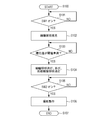
- FIG. 5 is a flowchart illustrating an example of a processing procedure of a method for controlling the ophthalmologic imaging apparatus in anterior eye iris imaging according to the first embodiment of this invention. It is a figure which shows the 1st Embodiment of this invention and shows an example of the light beam distribution of an illumination light source.
- FIG. 1 is a schematic diagram showing an example of a schematic configuration of an ophthalmologic imaging apparatus according to the first embodiment of the present invention.
- An ophthalmic imaging apparatus 100 illustrated in FIG. 1 is an apparatus that captures an image of the eye E and captures an image related to the eye E. In FIG. 1, only the eye E to be examined is shown in each part of the subject.
- An ophthalmic imaging apparatus 100 shown in FIG. 1 includes a base unit (1 to 5) that supports the entire ophthalmic imaging apparatus 100, a head unit (6) having an imaging mechanism, and an operation for an operator such as a doctor to operate. A portion (8) is provided.
- the base unit of the ophthalmic imaging apparatus 100 includes a base 1, a face holder 2, a chin rest 3, a zx stage 4, and a y stage 5.
- the subject puts his forehead on the face holder 2, puts his chin on the chin rest 3, and stops his face and eyes at the time of photographing.
- the zx stage 4 is movable in the zx direction on the base 1, and the y stage 5 is movable in the y direction.
- the head unit of the ophthalmic imaging apparatus 100 is configured to include the optical main body 6.
- the optical body 6 has a series of configurations that illuminate the subject eye E and shoot, and record an image of the subject eye E obtained as a result as the subject eye image.
- the head of the ophthalmic imaging apparatus 100 moves back and forth / left / right / up and down on the base 1 by the movement of the zx stage 4 and the y stage 5 to align the optical body 6 with respect to the subject. Is possible.
- the optical system of the optical body 6 is roughly divided into a photographing light source unit O1, an observation light source unit O2, an illumination optical system O3, a photographing / illumination optical system O4, a photographing optical system O5, and an internal fixation lamp unit O6. .
- the luminous flux emitted by the imaging light source unit O1 or the observation light source unit O2 illuminates the subject's eye E through the illumination optical system O3 and the imaging / illumination optical system O4, and the image is captured / illuminated.
- An image is formed on the image sensor 55 through the optical system O4 and the photographing optical system O5.
- the imaging light source unit O1 generates ring light of white light that is visible light with the following configuration.
- the imaging light source 11 is configured by, for example, a white LED array in which white LEDs that emit white light that is visible light are arranged in an annular shape.
- the photographing condenser lens 12 is a general spherical lens.
- the photographing ring slit 13 is a flat plate having an annular opening.
- the photographing lens baffle 14 is also a flat plate having an annular opening.
- the white light beam from the imaging light source 11 is condensed toward the fundus of the eye E by the imaging condenser lens 12, and the light beam shape when passing through the anterior eye part of the eye E by the imaging ring slit 13 is annular. It is molded to be. Further, the photographing lens baffle 14 restricts the light beam projected onto the crystalline lens of the eye E to prevent unwanted reflection light from the crystalline lens of the eye E to be detected in the fundus image.
- the observation light source unit O2 creates an infrared ring illumination with the following configuration.
- the observation light source 21 is a light source capable of continuous light emission, such as a halogen lamp or LED, and emits infrared light due to the characteristics of the element or an optical filter.
- the observation condenser lens 22 is a general spherical lens.
- the observation ring slit 23 is a flat plate having an annular opening.
- the observation lens baffle 24 is also a flat plate having an annular opening.
- Each configuration of the observation light source unit O2 is different from each configuration of the imaging light source unit O1 only in the type of the light source. That is, the observation condenser lens 22 condenses the light beam from the observation light source 21 toward the fundus of the eye E, the observation ring slit 23 adjusts the shape of the light beam in the anterior eye portion of the eye E, and the observation lens baffle 24 This prevents the reflected light from the crystalline lens of the eye E from being mixed into the fundus image.
- the illumination optical system O3 relays the light beams generated by the photographing light source unit O1 and the observation light source unit O2 and creates an index image for focusing the fundus image with the following configuration.
- the light beam generated by the visible light source O1 is reflected, and the light beam generated by the observation light source unit O2 is transmitted and guided to the illumination optical system O3.
- the first illumination relay lens 32 and the second illumination relay lens 34 form an image of ring illumination on the eye E by these.
- the split unit 33 includes a focus index light source 33a, a prism 33b, a focus index mask 33c, a split shift drive motor M1, and a split position sensor S1.
- the focus index light source 33a emits light for projecting the focus index.
- the prism 33b is for dividing light.
- the focus index mask 33c shows the outline of the focus index.
- the split shift drive motor M1 is for shifting the focus index in the optical axis direction by moving the configuration of 33a to 33c in the direction of the arrow in the drawing (changing the focus state of the focus index).
- the split position sensor S1 is for detecting a stop position of the configuration of 33a to 33c.
- the split insertion / extraction drive motor M2 is a motor for moving the split unit 33 forward and backward with respect to the illumination optical system O3. Specifically, the split insertion / extraction drive motor M2 projects the split index in the observation image by causing the split unit 33 to enter the illumination optical system O3 when observing the eye E. Further, the split insertion / extraction drive motor M2 performs control so that the split unit 33 is removed from the illumination optical system O3 when the eye E is photographed, and the focus index is not reflected in the photographed image.
- the corneal baffle 35 is for preventing reflection of reflected light from the cornea of the eye E to be examined that is unnecessary for the fundus image.
- the imaging / illumination optical system O4 projects an illumination light beam onto the eye E and derives an image related to the eye E with the following configuration.
- the perforated mirror 41 has a mirror at the outer periphery and a hole at the center.
- the light beam guided from the illumination optical system O ⁇ b> 3 is reflected by the mirror portion of the perforated mirror 41 and illuminates the fundus of the eye E through the objective lens 42.
- the fundus image of the eye E to be examined obtained by the illumination returns to the objective lens 42 and is led to the photographing optical system O5 through the hole in the center of the perforated mirror 41.
- the anterior eye illumination light source unit 43 is a light source for illuminating the anterior eye portion of the eye E to be examined.
- the anterior eye illumination light diffusion plate 44 is a diffusion plate for diffusing light from the anterior eye illumination light source unit 43.
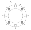
- FIG. 2 is a diagram showing an example of a detailed configuration of the anterior ocular photographing illumination light source unit shown in FIG. 1 according to the first embodiment of the present invention.
- the anterior eye illumination light source unit 43 includes an anterior eye illumination light source substrate 43p, anterior eye illumination white LEDs 43a to 43d, and anterior eye illumination infrared LEDs 43e to 43h.
- the anterior eye illumination light source substrate 43p is an annular printed circuit board disposed on the outer periphery of the objective lens 42 shown in FIG.
- the anterior eye illumination white LEDs 43a to 43d and the anterior eye illumination infrared LEDs 43e to 43h are mounted in an annular shape on the anterior eye illumination light source substrate 43p.
- the anterior eye illumination infrared LEDs 43e to 43h (first illumination means) illuminate the anterior eye portion of the eye E with infrared light
- the anterior eye illumination white LEDs 43a to 43d second illumination.
- Means illuminates the anterior segment of the eye E with visible light.
- the turning on and off of the anterior illumination white LEDs 43a to 43d and the turning on and off of the anterior illumination infrared LEDs 43e to 43h are controlled by a CPU 71 described later.
- the anterior eye illumination light diffusing plate 44 shown in FIG. 1 diffuses light beams from the anterior eye illumination white LEDs 43a to 43d and the anterior eye illumination infrared LEDs 43e to 43h, thereby uniformly diffusing light to the anterior eye portion of the eye E to be examined. It functions to irradiate (white light or infrared light).
- four examples of the anterior illumination white LEDs 43a to 43d and the anterior illumination infrared LEDs 43e to 43h are provided.
- the present embodiment is not limited to this. It is not something. These numbers are determined in order to create uniform illumination and emit a sufficient amount of light for photographing, and may be other than four.
- the imaging optical system O5 forms an image on the image sensor 55 after adjusting the focus of the fundus image of the eye E to be examined with the following configuration.
- the diopter correction lens 51 includes a convex lens (51a) and a concave lens (movable on the optical axis) that can be moved forward and backward in order to focus on the fundus of the eye E to be inspected with myopia or hyperopia, which is difficult to adjust with the focus lens 52. 51b).
- the diopter correction lens advance / retreat drive motor M4 allows the diopter correction-lens 51b to enter when the subject has high myopia, and diopter correction + lens 51a when the subject has high myopia. Is inserted into the photographing optical system O5.
- the focus lens 52 is a lens for adjusting the focus of the photographic light beam that has passed through the central hole of the perforated mirror 41, and performs focus adjustment by moving in the direction of the arrow in the figure.
- the focus lens drive motor M3 is for driving the focus lens 52 to focus
- the focus lens position sensor S3 is for detecting the stop position of the focus lens 52.
- the photographic lens 53 is a lens for imaging the light flux so far.
- the half mirror 54 splits the photographing light flux.
- the image sensor 55 photoelectrically converts the photographic light.
- the electrical signal obtained by the image sensor 55 is A / D converted by the image processing unit 72 to become digital data.
- an image after image processing by the image processing unit 72 is displayed on the monitor 73, and after shooting, for example, an image after image processing by the image processing unit 72 is recorded on the recording medium 74 (this An image may be displayed on the monitor 73).
- the optical path is separated from the photographing optical system O5 by the half mirror 54, and the internal fixation lamp unit 61 faces the optical path.
- the internal fixation lamp unit 61 is composed of a plurality of LEDs, and lights the LEDs at positions corresponding to the fixation unit selected by the inspector (operator). Then, the examiner can obtain a fundus image or the like in a desired direction when the examinee fixes the lighted LED.
- the optical body 6 is provided with a CPU 71, an image processing unit 72, a monitor 73, and a recording medium 74.
- the CPU 71 comprehensively controls the operation of the ophthalmic imaging apparatus 100 by controlling each component in the ophthalmic imaging apparatus 100 as necessary.
- the image processing unit 72 performs image processing on the electrical signal obtained by the imaging element 55 to generate an image related to the eye E.
- the monitor 73 displays an image or the like obtained by the image processing unit 72. Furthermore, the monitor 73 displays various information based on the control of the CPU 71, for example.
- the recording medium 74 is for recording an image or the like obtained by the image processing unit 72. Further, for example, the recording medium 74 records various types of information based on the control of the CPU 71, and also records programs and the like processed by the CPU 71.
- the operation unit 8 includes a joystick 81 and a shooting mode changeover switch 82.
- the joystick 81 is disposed at a predetermined position on the base 1.
- the joystick 81 is configured to tilt in the front-rear and left-right directions as a whole, and includes a photographing switch 81a, a vertical movement dial 81b, and a focus dial 81c.
- the operator tilts the entire joystick 81 in a desired direction when moving the head portion (6) forward, backward, left and right.
- the operator depresses the photographing switch 81a when photographing the eye E, rotates the vertical dial 81b when moving the head portion (6) in the vertical direction, and rotates the focus dial 81c when changing the focus state. Let All of these operations are detected by the CPU 71 via a sensor (not shown).
- the CPU 71 drives an x / y / z actuator (not shown), a split insertion / removal drive motor M2 or a focus lens as necessary.
- the drive motor M3 is driven.
- the photographing switch 81a is a two-stage switch.
- the first-stage switch of the shooting switch 81a inputs an operation of a shooting preparation operation such as an AE (automatic exposure adjustment) operation or an AF (automatic focus adjustment) operation, and the second-stage switch of the shooting switch 81a is It is assigned to input the operation of the shooting operation.
- the photographing mode changeover switch 82 is disposed at a predetermined position on the zx stage 4. Each time this photographing mode changeover switch 82 is pressed, the photographing mode is switched in the order of “fundus photographing” ⁇ “anterior illuminating photographing” ⁇ “anterior eye iris photographing” ⁇ “anterior eye photographing” ⁇ “fundus photographing”. It is like that.
- Front-eye transillumination is an imaging method for observing the turbidity of the crystalline lens of the eye E.
- the imaging light is emitted from the front of the eye E, and the fundus reflection light that has passed through the crystalline lens of the eye E is again the crystalline lens.
- An image based on the image when passing through is recorded.
- white light on the photographing optical axis emitted by the photographing light source unit O1 is used.
- Anterior eye iris photography is an imaging method for observing the iris part around the pupil of the eye E, and if the pupil is in a miosis, the iris part of the eye E is enlarged and an image with better observability is obtained. Is obtained.
- An operation method of the ophthalmologic imaging apparatus 100 in this anterior eye iris photographing will be described below with reference to FIG.
- FIG. 3 is a flowchart illustrating an example of a processing procedure of the control method of the ophthalmologic imaging apparatus in anterior eye iris imaging according to the first embodiment of this invention.
- step S100 is triggered by the operation of the imaging mode switching switch 82 by the operator to select “anterior eye iris imaging” and the CPU 71 detects this.
- step S101 the CPU 71 determines whether or not the photographing switch 81a is operated by the operator and the switch SW1, which is the first-stage switch of the photographing switch 81a, is turned on.
- the process waits at step S101 until the switch SW1 is turned on.
- step S101 if the switch SW1 is turned on as a result of the determination in step S101, the process proceeds to step S102.
- the CPU 71 performs control for performing pupil reduction illumination on the eye E to be examined. Specifically, the CPU 71 performs control to irradiate the eye E (the anterior eye portion of the eye E) with white light emitted from the imaging light source unit O1 when observing the eye E before performing the anterior eye iris photographing. Then, the iris of the eye E is promoted to enlarge the iris.
- step S103 the CPU 71 determines the miosis state of the eye E to be examined. Specifically, the CPU 71 analyzes the observation image of the eye E imaged on the image sensor 55 via the image processing unit 72 and determines whether or not the pupil diameter is less than the threshold (in the present embodiment). And determine whether or not the pupil diameter is sufficiently small to observe the iris portion).
- the process waits in step S103 until the pupil diameter is less than the threshold value.
- step S104 if the pupil diameter is less than the threshold value as a result of the determination in step S103, the process proceeds to step S104.
- step S104 the CPU 71 performs control to turn off the miosis illumination and turn on the anterior illumination infrared LEDs 43e to 43h of the anterior illumination light source unit 43.
- the anterior eye illumination infrared LEDs 43e to 43h By turning on the anterior eye illumination infrared LEDs 43e to 43h, the anterior eye portion of the eye E is illuminated with infrared light, and the anterior eye portion of the eye E can be observed.
- step S105 the CPU 71 determines whether or not the photographing switch 81a is operated by the operator and the switch SW2, which is the second-stage switch of the photographing switch 81a, is turned on.
- the process waits at step S105 until the switch SW2 is turned on.
- step S105 if the switch SW2 is turned on as a result of the determination in step S105, the process proceeds to step S106.
- step S106 the CPU 71 turns off the anterior illumination white LEDs 43a to 43d of the anterior illuminating light source unit 43 after turning off the anterior illuminating infrared LEDs 43e to 43h lit in step S104. I do.
- step S107 the CPU 71 records the image obtained by the photographing operation in step S106 on the recording medium 74 or displays it on the monitor 73, and then ends the processing of the flowchart shown in FIG.
- the pupil can be reduced to enlarge the area of the iris portion, and the photography is completed with a necessary amount of white light projection. Therefore, the glare felt by the subject is small.
- the pupil diameter is used as a criterion for turning off the miosis illumination (S103).
- the present invention is not limited to this mode. For example, whether or not the miosis illumination is turned off depending on whether or not the illumination time of the miosis illumination (visible light illumination) has passed a predetermined time. It is also possible to use a criterion for determining whether or not. Further, for example, as a determination criterion for turning off the miosis illumination, other determination criteria such as the number of blinks of the miosis illumination can be used.
- Anterior eye extraocular photography is an imaging method for associating the face of the subject in a series of fundus examinations or for recording the state of the eye E around the eyeball. It is. Therefore, photographing is performed using the anterior illumination white LEDs 43a to 43d with little direct reflection.
- FIG. 4 is a diagram illustrating an example of a light flux distribution of an illumination light source according to the first embodiment of this invention.
- the illumination light of the eye E the condensed white light generated by the imaging light source unit O1, the condensed infrared light generated by the observation light source unit O2, and the diffused white light generated by the anterior illumination light source unit 43 are used. There is light and diffuse infrared light.
- the arrow in FIG. 4 indicates the vector of the luminous flux distribution of the illumination light source.
- the light generated by the imaging light source unit O1 and the observation light source unit O2 is condensed light that projects the images of the imaging ring slit 13 and the observation ring slit 23 onto the fundus of the eye E to be examined. That is, as shown in FIG. 4, these lights are condensed lights that illuminate the eye E from the photographing optical axis via the objective lens 42. Therefore, these lights have a strong directivity, and are only light having a diameter of about the pupil diameter at the time of fundus photography, and slightly spread by separating the head part (6) from the subject at the time of anterior eye photography. However, it is still a narrow luminous flux. An image of light having directivity is a flat and high-contrast image because almost no shadow is generated.
- the light generated by the anterior eye illumination light source unit 43 is diffused by the anterior eye illumination light diffusing plate 44 and becomes uniform diffused light including the periphery of the eye E to be examined. That is, as shown in FIG. 4, these lights are diffused lights that illuminate the eye E from outside the imaging optical axis without passing through the objective lens 42. Therefore, these lights are a collection of light beams having weak and multi-directional vectors as illumination light, and an image obtained from such a light source is made by soft reflected light and shadows, and thus becomes a soft image. .
- the fundus image of the eye E to be examined is illuminated from a narrow gap called a pupil, and the collected light is required to take a reflected image of the retina with low reflectivity.
- the transillumination image of the eye E requires light that has passed through the pupil, and thus condensed light is required.
- the iris image and external eye image of the eye E are directly illuminated without passing through the pupil. For this reason, the condensed light is too high in contrast and is not suitable for a diagnosis target. On the contrary, if the light is diffused, a soft image is obtained, which is suitable for a diagnosis target.
- FIG. 5 is a flowchart illustrating an example of a processing procedure of the control method of the ophthalmologic imaging apparatus in the anterior segment imaging of the eye to be examined according to the first embodiment of the present invention.
- the flowchart shown in FIG. 5 starts when the anterior segment imaging standby state is entered (S200). At this time, in the ophthalmic imaging apparatus 100, the anterior eye illumination infrared LEDs 43e to 43h are turned on under the control of the CPU 71, and the anterior eye portion of the eye E to be examined is in an observation state.
- step S201 the CPU 71 determines whether or not the photographing switch 81a is operated by the operator and the switch SW1, which is the first-stage switch of the photographing switch 81a, is turned on.
- step S201 the process waits in step S201 until the switch SW1 is turned on.
- step S201 if the switch SW1 is turned on as a result of the determination in step S201, the process proceeds to step S202.
- step S202 the CPU 71 controls to turn off the anterior illumination infrared LEDs 43e to 43h (first illumination means) and turn on the anterior illumination white LEDs 43a to 43d (second illumination means) instead. Do.
- step S203 the CPU 71 performs photometric processing in the anterior segment of the eye E to be examined.
- This photometric process is for performing AE (automatic exposure adjustment), which is one of the adjustments of the imaging conditions in the imaging operation of the anterior segment of the eye E (S207 in the post-process).
- step S204 the CPU 71 performs a distance measurement process in the anterior segment of the eye E to be examined.
- This distance measurement process is for performing AF (automatic focus adjustment), which is one of the adjustments of the imaging conditions in the imaging operation of the anterior segment of the eye E (S207 in the post-process).
- the photographing condition adjustment processing in steps S203 and S204 is performed by processing the image obtained by the image sensor 55 after the processing in step S202 by the CPU 71 via the image processing unit 72.
- the CPU 71 that performs the shooting condition adjustment process in steps S203 and S204 constitutes a shooting condition adjustment unit.
- step S205 the CPU 71 performs control to turn off the anterior illumination white LEDs 43a to 43d (second illumination means) and turn on the anterior illumination infrared LEDs 43e to 43h (first illumination means).
- the lighting time of the anterior illumination white LEDs 43a to 43d related to the processing from step S202 to step S205 is about several tens of msec.
- step S206 the CPU 71 determines whether or not the photographing switch 81a is operated by the operator and the switch SW2, which is the second-stage switch of the photographing switch 81a, is turned on.
- the process waits at step S206 until the switch SW2 is turned on.
- step S206 if the switch SW2 is turned on as a result of the determination in step S206, the process proceeds to step S207.
- step S207 the CPU 71 turns off the anterior-eye illumination infrared LEDs 43e to 43h turned on in step S205 and turns on the photographing illumination white LEDs 43a to 43d to perform a photographing operation.
- shooting is performed based on AE (automatic exposure adjustment) adjusted by the process of step S203, AF (automatic focus adjustment) adjusted by the process of step S204, and the like.
- step S208 the CPU 71 records the image obtained by the photographing operation in step S207 on the recording medium 74 or displays it on the monitor 73, and then ends the processing of the flowchart shown in FIG.
- the imaging of the anterior segment of the eye E is performed under visible white light. Therefore, it is desirable that the adjustment of the photographing conditions, that is, the automatic adjustment operation such as AE (automatic exposure adjustment) / AF (automatic focus adjustment) is performed under illumination of white light.
- the automatic adjustment operation such as AE (automatic exposure adjustment) / AF (automatic focus adjustment) is performed under illumination of white light.
- the shooting conditions are adjusted under infrared light illumination, the photometric value and the distance measurement value will be shifted due to the wavelength difference from the white light used for actual shooting. Because it depends, correction becomes difficult.
- the schematic configuration of the ophthalmic imaging apparatus according to the second embodiment is the same as the schematic configuration of the ophthalmic imaging apparatus 100 according to the first embodiment shown in FIG.
- FIG. 6 is a flowchart illustrating an example of a processing procedure of the control method of the ophthalmologic imaging apparatus in the anterior segment imaging of the eye to be examined according to the second embodiment of the present invention.
- the flowchart shown in FIG. 6 starts when the anterior segment imaging standby state is entered (S300). At this time, in the ophthalmic imaging apparatus 100, the anterior eye illumination infrared LEDs 43e to 43h are turned on under the control of the CPU 71, and the anterior eye portion of the eye E to be examined is in an observation state.
- step S301 the CPU 71 determines whether or not the photographing switch 81a is operated by the operator and the switch SW1, which is the first-stage switch of the photographing switch 81a, is turned on.
- step S301 the process waits in step S301 until the switch SW1 is turned on.
- step S301 if the switch SW1 is turned on, the process proceeds to step S302.
- step S302 the CPU 71 performs photometric processing on the anterior segment of the eye E.
- This photometric processing is performed in the observation state of the anterior segment of the eye E (specifically, the anterior segment of the eye E is illuminated with infrared light from the anterior illumination infrared LEDs 43e to 43h). Done.
- step S303 the CPU 71 performs a distance measurement process in the anterior segment of the eye E to be examined.
- This distance measurement processing is an observation state of the anterior segment of the eye E (specifically, a state in which the anterior segment of the eye E is illuminated with infrared light from the anterior illumination infrared LEDs 43e to 43h). Done in
- the processing in steps S302 and S303 is performed by the CPU 71 processing the image obtained by the imaging device 55 in the observation state of the anterior eye portion of the eye E to be examined via the image processing unit 72.
- the anterior eye portion of the eye E is illuminated with infrared light from the anterior eye illumination infrared LEDs 43e to 43h. Therefore, the photometry value and the distance measurement value obtained by the processing in steps S302 and S303 are optimized for infrared light, and are optimal in the observation state of the anterior segment of the eye E to be examined by infrared light.
- the processing in steps S302 and S303 is processing for obtaining an optimal observation image (observation image) of the anterior eye portion of the eye E in the observation state of the anterior eye portion of the eye E.
- step S304 the CPU 71 determines whether or not the photographing switch 81a is operated by the operator and the switch SW2, which is the second-stage switch of the photographing switch 81a, is turned on.
- the process waits at step S304 until the switch SW2 is turned on.
- step S304 if the switch SW2 is turned on, the process proceeds to step S305.
- step S305 the CPU 71 turns off the anterior eye illumination infrared LEDs 43e to 43h (first illumination means), and controls to turn on the anterior eye illumination white LEDs 43a to 43d (second illumination means) instead. Do.
- step S306 the CPU 71 performs a photometric process on the anterior segment of the eye E to be examined.
- This photometric processing is for performing AE (automatic exposure adjustment), which is one of the adjustments of the imaging conditions in the imaging operation of the anterior eye part of the eye E (post-step S308).
- step S307 the CPU 71 performs a distance measurement process in the anterior segment of the eye E to be examined.
- This distance measurement process is for performing AF (automatic focus adjustment), which is one of the adjustments of the imaging conditions in the imaging operation of the anterior segment of the eye E (S308 in the post-process).
- the photographing condition adjustment process in steps S306 and S307 is performed by processing the image obtained by the image sensor 55 after the process in step S305 by the CPU 71 via the image processing unit 72.
- the CPU 71 that performs the shooting condition adjustment process in steps S306 and S307 constitutes a shooting condition adjustment unit.
- step S308 the CPU 71 performs a shooting operation in the state of step S305 (that is, the anterior eye illumination infrared LEDs 43e to 43h are turned off and the shooting illumination white LEDs 43a to 43d are turned on).
- photographing is performed based on AE (automatic exposure adjustment) adjusted by the process in step S306, AF (automatic focus adjustment) adjusted by the process in step S307, and the like.
- step S309 the CPU 71 records the image obtained by the photographing operation in step S308 on the recording medium 74 or displays it on the monitor 73, and then ends the processing of the flowchart shown in FIG.
- the imaging condition such as AE / AF can be adjusted just by emitting white light of about several tens of msec after the observation and immediately before imaging. It is possible to perform a suitable shooting without a feeling of strangeness.
- the present embodiment it is possible to increase the accuracy of adjustment of imaging conditions such as AE / AF while minimizing the glare felt by the subject. As a result, it is possible to easily and suitably perform imaging in the anterior segment of the eye E, and obtain an anterior segment image with good appearance.
- the present invention can also be realized by executing the following processing.
- software that realizes the functions of the above-described embodiments is supplied to a system or apparatus via a network or various storage media, and a computer (or CPU, MPU, etc.) of the system or apparatus reads the program. It is a process to be executed.
- This program and a computer-readable recording medium storing the program are included in the present invention.
Landscapes
- Life Sciences & Earth Sciences (AREA)
- Health & Medical Sciences (AREA)
- Medical Informatics (AREA)
- Biophysics (AREA)
- Ophthalmology & Optometry (AREA)
- Engineering & Computer Science (AREA)
- Biomedical Technology (AREA)
- Heart & Thoracic Surgery (AREA)
- Physics & Mathematics (AREA)
- Molecular Biology (AREA)
- Surgery (AREA)
- Animal Behavior & Ethology (AREA)
- General Health & Medical Sciences (AREA)
- Public Health (AREA)
- Veterinary Medicine (AREA)
- Eye Examination Apparatus (AREA)
Abstract
被検眼の前眼部における撮影を簡便かつ好適に行えるようにするとともに、見えの良い前眼部画像を得ることが可能な仕組みを提供する。 撮影を行う前の被検眼の前眼部の観察中であって撮影条件の調整(S203及びS204)を行うときに、被検眼の前眼部を撮影光である白色光で照明し(S202)、撮影を行う前の被検眼の前眼部の観察中であって前記撮影条件の調整を行わないときに、被検眼の前眼部を撮影光である赤外光で照明する(S205)。
Description
本発明は、被検眼を撮影して当該被検眼に係る画像を撮像する眼科撮像装置及びその制御方法に関するものである。
従来の眼科撮像装置は、被検眼の眼底部を撮影することに特化して光学系の配置が行われている。しかしながら、眼科撮像装置と被検者との距離を離すことによって被検眼の前眼部の撮影も可能であり、眼科撮像装置の光学本体と被検者との距離の調整量を大きくすることにより、被検眼の前眼部の撮影も可能とした眼科撮像装置が広く知られている。
例えば、下記の特許文献1では、前眼部照明光源の前方に可視光カットフィルタを挿抜自在に配置することにより、1つの光源で被検眼の前眼部の観察と撮影を実現している。つまり、特許文献1では、被検眼の前眼部の観察時には、可視光カットフィルタを挿入することにより当該前眼部を赤外光で照明している。また、特許文献1では、被検眼の前眼部の撮影時には、可視光カットフィルタを抜去することにより当該前眼部を光軸上から可視光等で照明し、その眼底反射光によって徹照像を得るようにしている。
しかしながら、上記の特許文献1に記載の技術は、被検眼の前眼部における撮影時のAE(Automatic Exposure:自動露光量調整)やAF(Auto Focus:自動焦点調整)といった撮影条件を考慮したものではなかった。このため、被検眼の前眼部における撮影を簡便かつ好適に行うことができず、また、見えの良い前眼部画像を得ることも難しかった。
本発明は、このような問題点に鑑みてなされたものであり、被検眼の前眼部における撮影を簡便かつ好適に行えるようにするとともに、見えの良い前眼部画像を得ることが可能な仕組みを提供することを目的とする。
なお、前記目的に限らず、後述する発明を実施するための形態に示す各構成により導かれる作用効果であって、従来の技術によっては得られない作用効果を奏することも本件の他の目的の1つとして位置付けることができる。
本発明の眼科撮像装置は、被検眼を撮影して前記被検眼に係る画像を撮像する眼科撮像装置であって、前記被検眼の前眼部を赤外光で照明する第1の照明手段と、前記被検眼の前眼部を可視光で照明する第2の照明手段と、前記被検眼の前眼部の撮影における撮影条件の調整を行う撮影条件調整手段と、を有し、前記撮影を行う前の前記被検眼の前眼部の観察中であって前記撮影条件調整手段による前記撮影条件の調整を行うときに、前記第2の照明手段において前記被検眼の前眼部を可視光で照明し、前記観察中であって前記撮影条件調整手段による前記撮影条件の調整を行わないときに、前記第1の照明手段において前記被検眼の前眼部を赤外光で照明する。
本発明の眼科撮像装置における他の態様は、被検眼を撮影して前記被検眼に係る画像を撮像する眼科撮像装置であって、前記被検眼の前眼部を赤外光で照明する第1の照明手段と、前記被検眼の前眼部を可視光で照明する第2の照明手段と、前記被検眼の前眼部の撮影における撮影条件の調整を行う撮影条件調整手段と、を有し、前記撮影を行う前の前記被検眼の前眼部の観察中であって前記撮影条件調整手段による前記撮影条件の調整を行うときに、前記第1の照明手段において前記被検眼の前眼部を赤外光で照明し、前記観察の終了後の前記撮影における前であって前記撮影条件調整手段による前記撮影条件の調整を行うときに、前記第2の照明手段において前記被検眼の前眼部を可視光で照明する。
また、本発明は、上述した眼科撮像装置の制御方法を含む。
本発明によれば、被検眼の前眼部における撮影を簡便かつ好適に行うことができるとともに、見えの良い前眼部画像を得ることができる。
以下に、図面を参照しながら、本発明を実施するための形態(実施形態)について説明する。
(第1の実施形態)
まず、本発明の第1の実施形態について説明を行う。
まず、本発明の第1の実施形態について説明を行う。
図1は、本発明の第1の実施形態に係る眼科撮像装置の概略構成の一例を示す模式図である。図1に示す眼科撮像装置100は、被検眼Eを撮影して当該被検眼Eに係る画像を撮像する装置である。なお、図1には、被検者の各部のうち被検眼Eのみを図示している。
図1に示す眼科撮像装置100は、当該眼科撮像装置100の全体を支えるベース部(1~5)と、撮影機構を有するヘッド部(6)と、医師等の操作者が操作するための操作部(8)を備えて構成されている。
眼科撮像装置100のベース部は、ベース1、顔受け2、顎受け3、z-xステージ4、及び、yステージ5を有して構成されている。
被検者は、顔受け2に額を合わせ、顎受け3に顎を乗せ、撮影時に顔及び眼を静止させる。z-xステージ4は、ベース1上をz-x方向に移動可能であり、yステージ5は、y方向に移動可能である。
被検者は、顔受け2に額を合わせ、顎受け3に顎を乗せ、撮影時に顔及び眼を静止させる。z-xステージ4は、ベース1上をz-x方向に移動可能であり、yステージ5は、y方向に移動可能である。
眼科撮像装置100のヘッド部は、光学本体6を有して構成されている。この光学本体6は、被検眼Eを照明して撮影を行い、その結果得られる被検眼Eに係る像を被検眼画像として記録する一連の構成を有している。また、眼科撮像装置100のヘッド部は、z-xステージ4とyステージ5の移動によって、ベース1上で前後/左右/上下に移動して被検者に対して光学本体6の位置合わせを行うことが可能である。
以下に、光学本体6の詳細な構成について説明する。
光学本体6の光学系は、大まかに分けると、撮影光源部O1、観察光源部O2、照明光学系O3、撮影/照明光学系O4、撮影光学系O5、内部固視灯部O6から構成される。撮影光源部O1、または、観察光源部O2によって射出された光束は、照明光学系O3、撮影/照明光学系O4を経て、被検者の被検眼Eを照明し、その像は、撮影/照明光学系O4、撮影光学系O5を経て撮像素子55に結像される。
撮影光源部O1は、以下のような構成により、可視光である白色光のリング照明を作り出す。
撮影光源11は、例えば、可視光である白色光を発光する白色LEDを円環状に配置した白色LEDアレイによって構成されている。
撮影コンデンサレンズ12は、一般的な球面レンズである。
撮影リングスリット13は、環状の開口を持った平板である。
撮影水晶体バッフル14は、これも環状の開口を持った平板である。
撮影光源11からの白色光の光束は、撮影コンデンサレンズ12によって被検眼Eの眼底に向けて集光され、撮影リングスリット13によって被検眼Eの前眼部を通過する際の光束形状が環状となるよう成形される。さらに、撮影水晶体バッフル14によって、被検眼Eの水晶体へ投影される光束を制限し、眼底像に不要な被検眼Eの水晶体からの反射光が混入することを防いでいる。
観察光源部O2は、以下のような構成により、赤外光のリング照明を作り出す。
観察光源21は、例えば、ハロゲンランプやLEDなど連続発光可能な光源であり、素子の特性や光学フィルタによって赤外光を発光する。
観察コンデンサレンズ22は、一般的な球面レンズである。
観察リングスリット23は、環状の開口を持った平板である。
観察水晶体バッフル24は、これも環状の開口を持った平板である。
この観察光源部O2の各構成は、撮影光源部O1の各構成と光源の種類が異なるだけである。即ち、観察コンデンサレンズ22で観察光源21からの光束を被検眼Eの眼底に向けて集光し、観察リングスリット23で被検眼Eの前眼部での光束の形状を整え、観察水晶体バッフル24で眼底像に被検眼Eの水晶体からの反射光が混入するのを防ぐ。
照明光学系O3は、以下のような構成により、撮影光源部O1、観察光源部O2で生成された光束をリレーするとともに、眼底像の焦点合わせのための指標像を造りこむ。
ダイクロイックミラー31では、撮影光源部O1で生成された可視光による光束は反射し、観察光源部O2で生成された赤外光による光束は透過させて照明光学系O3に導光する。
第1の照明リレーレンズ32、及び、第2の照明リレーレンズ34は、これらによってリング照明を被検眼Eに結像する。
スプリットユニット33は、フォーカス指標光源33a、プリズム33b、フォーカス指標マスク33c、スプリットシフト駆動モータM1、及び、スプリット位置センサS1を備えて構成されている。フォーカス指標光源33aは、フォーカス指標を投影するための光を発する。プリズム33bは、光を分割等するためのものである。フォーカス指標マスク33cは、フォーカス指標の外形を示すものである。スプリットシフト駆動モータM1は、33a~33cの構成を図中の矢印方向に移動させることでフォーカス指標を光軸方向にシフト移動させる(フォーカス指標の焦点状態を変化させる)ためのものである。スプリット位置センサS1は、33a~33cの構成の停止位置を検出するためのものである。
スプリット挿抜駆動モータM2は、スプリットユニット33を照明光学系O3に対して進退させるためのモータである。具体的に、スプリット挿抜駆動モータM2は、被検眼Eの観察時には、スプリットユニット33を照明光学系O3に進入させて観察像の中にスプリット指標を投影する。また、スプリット挿抜駆動モータM2は、被検眼Eの撮影時には、スプリットユニット33を照明光学系O3から抜去させ、撮影像の中にフォーカス指標が写りこむことがないように制御する。
角膜バッフル35は、眼底像に不要な被検眼Eの角膜からの反射光の写りこみを防ぐためのものである。
撮影/照明光学系O4は、以下のような構成により、被検眼Eに対して照明光束を投影するとともに、被検眼Eに係る像を導出する。
穴あきミラー41は、外周部がミラー、中央部が穴となっている。照明光学系O3から導かれた光束は、穴あきミラー41のミラー部分で反射して、対物レンズ42を介して被検眼Eの眼底を照明する。当該照明により得られた被検眼Eの眼底像は、対物レンズ42を戻り、穴あきミラー41の中央部の穴を通って撮影光学系O5に導出される。
前眼照明光源ユニット43は、被検眼Eの前眼部を照明するための光源である。
前眼照明光源ユニット43は、被検眼Eの前眼部を照明するための光源である。
前眼照明光拡散板44は、前眼照明光源ユニット43からの光を拡散させるための拡散板である。
ここで、前眼照明光源ユニット43の詳細な構成について説明を行う。
図2は、本発明の第1の実施形態を示し、図1に示す前眼撮影照明光源ユニットの詳細な構成の一例を示す図である。
図2に示すように、前眼照明光源ユニット43は、前眼照明光源基板43pと、前眼照明白色LED43a~43dと、前眼照明赤外LED43e~43hを備えて構成されている。前眼照明光源基板43pは、図1に示す対物レンズ42の外周部に配された円環状のプリント基板である。前眼照明白色LED43a~43d及び前眼照明赤外LED43e~43hは、前眼照明光源基板43p上に円環状に実装されている。ここで、前眼照明赤外LED43e~43h(第1の照明手段)は、被検眼Eの前眼部を赤外光で照明するものであり、前眼照明白色LED43a~43d(第2の照明手段)は、被検眼Eの前眼部を可視光で照明するものである。前眼照明白色LED43a~43dの点灯及び消灯、並びに、前眼照明赤外LED43e~43hの点灯及び消灯は、後述するCPU71によって制御される。
図1に示す前眼照明光拡散板44は、前眼照明白色LED43a~43dや前眼照明赤外LED43e~43hからの光束を拡散することにより、被検眼Eの前眼部に均一な拡散光(白色光や赤外光)を照射するために機能する。なお、図2に示す例では、前眼照明白色LED43a~43d及び前眼照明赤外LED43e~43hを、それぞれ、4個ずつ設けた例を示しているが、本実施形態においてはこれに限定されるものではない。これらの個数は、均一な照明を作り出すことと、撮影に十分な光量を発光するために決定されるものであり、4個以外の個数であってもよい。
ここで、再び、図1の説明に戻る。
撮影光学系O5は、以下のような構成により、被検眼Eの眼底像の焦点調節を行った上で撮像素子55に結像を行う。
視度補正レンズ51は、フォーカスレンズ52で焦点調整困難な強度の近視・遠視の被検眼Eの眼底にピントを合わせるために、光軸上に進退可能に設置される凸レンズ(51a)及び凹レンズ(51b)を備える。
視度補正レンズ進退駆動モータM4は、被検者が強度の近視である場合には視度補正-レンズ51bを進入させ、被検者が強度の遠視である場合には視度補正+レンズ51aを撮影光学系O5に対して挿入させる。
フォーカスレンズ52は、穴明きミラー41の中央の穴を通過した撮影光束の焦点調節を行うためのレンズであり、図中の矢印方向に移動することで焦点調節を行う。
フォーカスレンズ駆動モータM3は、フォーカスレンズ52を駆動して焦点を合わせるためのものであり、フォーカスレンズ位置センサS3は、フォーカスレンズ52の停止位置を検出するためのものである。
フォーカスレンズ駆動モータM3は、フォーカスレンズ52を駆動して焦点を合わせるためのものであり、フォーカスレンズ位置センサS3は、フォーカスレンズ52の停止位置を検出するためのものである。
撮影レンズ53は、ここまでの光束を結像するためのレンズである。
ハーフミラー54は、撮影光束を分割する。
撮像素子55は、撮影光を光電変換する。撮像素子55で得られた電気信号は、デジタルデータとすべく画像処理部72によってA/D変換される。そして、赤外観察時には、例えば画像処理部72による画像処理後の画像がモニタ73に表示され、撮影後には、例えば画像処理部72による画像処理後の画像が記録媒体74に記録される(当該画像がモニタ73に表示されてもよい)。
内部固視灯部O6は、ハーフミラー54によって、撮影光学系O5から光路が分かれて、その光路に対して内部固視灯ユニット61が対向している。
内部固視灯ユニット61は、複数のLEDによって構成され、検査者(操作者)が選択した固視部に対応した位置のLEDを点灯させる。そして、点灯したLEDを被検者が固視することにより、検査者は所望の向きの眼底像等を得ることができる。
さらに、光学本体6には、CPU71、画像処理部72、モニタ73、記録媒体74が設けられている。
CPU71は、必要に応じて眼科撮像装置100における各構成を制御することにより、眼科撮像装置100における動作を統括的に制御する。
画像処理部72は、撮像素子55で得られた電気信号を画像処理して、被検眼Eに係る画像を生成等する。
モニタ73は、画像処理部72で得られた画像等を表示するものである。さらに、モニタ73は、例えば、CPU71の制御に基づいて、各種の情報を表示する。
記録媒体74は、画像処理部72で得られた画像等を記録するものである。さらに、記録媒体74は、例えば、CPU71の制御に基づいて各種の情報を記録し、また、CPU71が処理するプログラム等を記録する。
操作部8は、ジョイスティック81、及び、撮影モード切り換えスイッチ82を有して構成されている。
ジョイスティック81は、ベース1の所定の位置に配置されている。このジョイスティック81は、全体が前後左右方向に傾倒するよう構成されており、撮影スイッチ81a、上下動ダイアル81b、及び、フォーカスダイアル81cを有して構成されている。操作者は、ヘッド部(6)を前後左右に動かす時にはジョイスティック81全体を所望の方向に傾倒させる。また、操作者は、被検眼Eの撮影をする時には撮影スイッチ81aを押し下げ、ヘッド部(6)を上下方向に動かす時には上下動ダイアル81bを回転させ、フォーカス状態を変更する時にはフォーカスダイアル81cを回転させる。これらの操作は、全て、不図示のセンサを介して、CPU71において検知され、CPU71は、必要に応じて、不図示のx/y/zアクチュエータを駆動したり、スプリット挿抜駆動モータM2やフォーカスレンズ駆動モータM3を駆動したりする。なお、撮影スイッチ81aは、二段階のスイッチとなっている。撮影スイッチ81aの一段階目のスイッチは、例えばAE(自動露光量調整)作動やAF(自動焦点調整)作動などの撮影準備動作の作動を入力し、撮影スイッチ81aの二段階目のスイッチは、撮影動作の作動を入力するよう割り付けられている。
撮影モード切り換えスイッチ82は、z-xステージ4上の所定の位置に配置されている。この撮影モード切り換えスイッチ82は、押すたびに、撮影モードが"眼底撮影"→"前眼徹照撮影"→"前眼虹彩撮影"→"前眼外眼撮影"→"眼底撮影"の順に切り替わるようになっている。
次に、被検眼Eの前眼部の撮影モードにおける撮影動作について説明を行う。
前眼徹照撮影は、被検眼Eの水晶体の混濁を観察するための撮影法であり、被検眼Eの正面から撮影光を発光し、被検眼Eの水晶体を通過した眼底反射光が再度水晶体を通過した際のその像に基づく画像を記録する。このときの撮影光としては、撮影光源部O1によって射出される撮影光軸上の白色光を用いる。
前眼虹彩撮影は、被検眼Eの瞳孔周辺の虹彩部を観察するための撮影法であり、瞳孔が縮瞳した状態であれば被検眼Eの虹彩部が拡大し、より観察性の良い画像が得られる。この前眼虹彩撮影における眼科撮像装置100の動作方法を図3を用いて以下に説明する。
図3は、本発明の第1の実施形態を示し、前眼虹彩撮影における眼科撮像装置の制御方法の処理手順の一例を示すフローチャートである。
まず、図3に示すステップS100の「START」は、操作者により撮影モード切り換えスイッチ82が操作されて"前眼虹彩撮影"が選択され、これをCPU71が検知することが契機となる。
前眼虹彩撮影が開始すると、ステップS101において、CPU71は、操作者により撮影スイッチ81aが操作されて、撮影スイッチ81aの一段階目のスイッチであるスイッチSW1がオンしたか否かを判断する。
この判断の結果、スイッチSW1がオンしていない(即ちオフである)場合には、スイッチSW1がオンするまで、ステップS101で待機する。
一方、ステップS101の判断の結果、スイッチSW1がオンした場合には、ステップS102に進む。
ステップS102に進むと、CPU71は、被検眼Eに対して縮瞳照明発光を行う制御をする。具体的に、CPU71は、前眼虹彩撮影を行う前の被検眼Eの観察時に、撮影光源部O1が発する白色光を被検眼E(被検眼Eの前眼部)に対して照射する制御を行って、被検眼Eの縮瞳を促して虹彩部を拡大させる。
続いて、ステップS103において、CPU71は、被検眼Eの縮瞳状態を判断する。具体的に、CPU71は、撮像素子55に結像された被検眼Eの観察像を画像処理部72を介して解析し、瞳孔径が閾値未満となったか否かを判断する(本実施形態では、瞳孔径が虹彩部の観察に十分な小ささになったか否かを判断する)。
この判断の結果、瞳孔径が閾値未満となっていない場合には、瞳孔径が閾値未満となるまで、ステップS103で待機する。
一方、ステップS103の判断の結果、瞳孔径が閾値未満となった場合には、ステップS104に進む。
ステップS104に進むと、CPU71は、縮瞳照明を消灯し、且つ、前眼照明光源ユニット43の前眼照明赤外LED43e~43hを点灯する制御を行う。この前眼照明赤外LED43e~43hを点灯することにより、被検眼Eの前眼部を赤外光で照明し、被検眼Eの前眼部の観察を行える。
続いて、ステップS105において、CPU71は、操作者により撮影スイッチ81aが操作されて、撮影スイッチ81aの二段階目のスイッチであるスイッチSW2がオンしたか否かを判断する。
この判断の結果、スイッチSW2がオンしていない(即ちオフである)場合には、スイッチSW2がオンするまで、ステップS105で待機する。
一方、ステップS105の判断の結果、スイッチSW2がオンした場合には、ステップS106に進む。
ステップS106に進むと、CPU71は、ステップS104で点灯させた前眼照明赤外LED43e~43hを消灯した上で、前眼照明光源ユニット43の前眼照明白色LED43a~43dを点灯させて、撮影動作を行う。
その後、ステップS107において、CPU71は、ステップS106の撮影動作により得られた画像を記録媒体74に記録し或いはモニタ73に表示等した後、図3に示すフローチャートの処理を終了する。
この図3に示すフローチャートの処理を経ることにより、前眼虹彩撮影において、瞳孔を縮瞳させて虹彩部の面積を大きくした撮影ができるとともに、必要量だけの白色光の投光で撮影が終了するので、被検者が感じる眩しさは小さくて済む。
なお、図3に示すフローチャートでは、縮瞳照明消灯の判定基準として瞳孔径を用いるものであった(S103)。しかしながら、本実施形態においては、この態様に限定されるものではなく、例えば、縮瞳照明(可視光の照明)の点灯時間が所定時間を経過したか否かによって縮瞳照明を消灯するか否かを判定する判定基準を用いることも可能である。また、例えば、縮瞳照明消灯の判定基準として、縮瞳照明の点滅回数などの他の判定基準を用いることも可能である。
前眼外眼撮影(前眼周辺像の撮影)は、一連の眼底検査の中で、その被検者の顔立ちを紐付けるためや、被検眼Eの眼球周囲の状態を記録するための撮影法である。したがって、直接反射の少ない、前眼照明白色LED43a~43dを用いた撮影を行う。
次に、照明光源による照明の性質の違いについて説明する。
図4は、本発明の第1の実施形態を示し、照明光源の光束分布の一例を示す図である。本実施形態においては、被検眼Eの照明光として、撮影光源部O1によって発生する集光白色光、観察光源部O2によって発生する集光赤外光、前眼照明光源ユニット43によって発生する拡散白色光及び拡散赤外光がある。
図4は、本発明の第1の実施形態を示し、照明光源の光束分布の一例を示す図である。本実施形態においては、被検眼Eの照明光として、撮影光源部O1によって発生する集光白色光、観察光源部O2によって発生する集光赤外光、前眼照明光源ユニット43によって発生する拡散白色光及び拡散赤外光がある。
図4中の矢印は、照明光源の光束分布のベクトルを示している。
撮影光源部O1や観察光源部O2によって発生する光は、撮影リングスリット13や観察リングスリット23の像を被検眼Eの眼底に投影する集光された光である。即ち、これらの光は、図4に示すように、対物レンズ42を介して撮影光軸上から被検眼Eを照明する集光された光である。したがって、これらの光は、指向性を強く持ち、眼底撮影時には瞳孔径程度の径しかない光であり、前眼撮影時には、ヘッド部(6)を被検者から離すことによって、やや広がりを持つが、それでも狭い光束である。指向性を持った光による画像は、影がほとんど発生しないため、フラットでハイコントラストな画像となる。
また、前眼照明光源ユニット43によって発生する光は、前眼照明光拡散板44によって拡散され、被検眼Eの周辺部まで含めて均一な拡散光となる。即ち、これらの光は、図4に示すように、対物レンズ42を介さず撮影光軸外から被検眼Eを照明する拡散光である。したがって、これらの光は、照明光としては、弱く多方向のベクトルを持った光線の集まりであり、そのような光源から得られる画像は、柔らかい反射光と影によって作られるので柔らかな画像となる。
被検眼Eの眼底像は、瞳孔という狭い隙間から照明し、反射率の低い網膜の反射像を撮影するために集光された光が必要になる。被検眼Eの徹照像も、同様に、瞳孔を通した光を必要とするので、集光された光が必要になる。
一方、被検眼Eの虹彩像や外眼像は、瞳孔を通さない直接的な照明になる。このため、集光された光では、コントラストが高すぎて診断対象には適さない。逆に、拡散された光であれば、柔らかい画像となるため、診断対象に適したものとなる。
次に、第1の実施形態の被検眼Eの前眼部撮影における処理手順について説明する。
図5は、本発明の第1の実施形態を示し、被検眼の前眼部撮影における眼科撮像装置の制御方法の処理手順の一例を示すフローチャートである。
この図5に示すフローチャートは、前眼部撮影待機状態となったことを契機としてスタートする(S200)。この際、眼科撮像装置100では、CPU71の制御によって、前眼照明赤外LED43e~43hが点灯し、被検眼Eの前眼部の観察状態となっているものとする。
そして、ステップS201において、CPU71は、操作者により撮影スイッチ81aが操作されて、撮影スイッチ81aの一段階目のスイッチであるスイッチSW1がオンしたか否かを判断する。
この判断の結果、スイッチSW1がオンしていない(即ちオフである)場合には、スイッチSW1がオンするまで、ステップS201で待機する。
一方、ステップS201の判断の結果、スイッチSW1がオンした場合には、ステップS202に進む。
ステップS202に進むと、CPU71は、前眼照明赤外LED43e~43h(第1の照明手段)を消灯し、代わりに、前眼照明白色LED43a~43d(第2の照明手段)を点灯する制御を行う。
続いて、ステップS203において、CPU71は、被検眼Eの前眼部における測光処理を行う。この測光処理は、被検眼Eの前眼部の撮影動作(後工程のS207)における撮影条件の調整の1つであるAE(自動露光量調整)を行うためのものである。
続いて、ステップS204において、CPU71は、被検眼Eの前眼部における測距処理を行う。この測距処理は、被検眼Eの前眼部の撮影動作(後工程のS207)における撮影条件の調整の1つであるAF(自動焦点調整)を行うためのものである。
このステップS203及びS204における撮影条件調整処理は、ステップS202の処理後に撮像素子55で得られた画像を、画像処理部72を介して、CPU71によって処理することによりなされる。このステップS203及びS204における撮影条件調整処理を行うCPU71は、撮影条件調整手段を構成する。
続いて、ステップS205において、CPU71は、前眼照明白色LED43a~43d(第2の照明手段)を消灯し、前眼照明赤外LED43e~43h(第1の照明手段)を点灯する制御を行う。ここで、本実施形態においては、ステップS202からステップS205までの処理に係る前眼照明白色LED43a~43dの点灯時間は、数十msec程度である。
続いて、ステップS206において、CPU71は、操作者により撮影スイッチ81aが操作されて、撮影スイッチ81aの二段階目のスイッチであるスイッチSW2がオンしたか否かを判断する。
この判断の結果、スイッチSW2がオンしていない(即ちオフである)場合には、スイッチSW2がオンするまで、ステップS206で待機する。
一方、ステップS206の判断の結果、スイッチSW2がオンした場合には、ステップS207に進む。
ステップS207に進むと、CPU71は、ステップS205で点灯させた前眼照明赤外LED43e~43hを消灯した上で、撮影照明白色LED43a~43dを点灯させて、撮影動作を行う。このステップS207の撮影動作においては、ステップS203の処理により調整されたAE(自動露光量調整)やステップS204の処理により調整されたAF(自動焦点調整)等に基づく撮影が行われる。
その後、ステップS208において、CPU71は、ステップS207の撮影動作により得られた画像を記録媒体74に記録し或いはモニタ73に表示等した後、図5に示すフローチャートの処理を終了する。
被検眼Eの前眼部撮影は、可視光である白色光の下で行われるものである。したがって、撮影条件の調整、つまりAE(自動露光量調整)/AF(自動焦点調整)といった自動調整動作は、白色光の照明下でやることが望ましい。ここで、赤外光の照明下で撮影条件の調整を行った場合、実際の撮影に用いる白色光との波長差によって、測光値も測距値もズレを生じてしまい、そのズレ量は被写体依存であるので、補正も難しくなる。
そこで、本実施形態では、図5に示すフローチャートのように、被検眼Eの前眼部の撮影前(被検眼Eの前眼部の観察中)であって、AE/AFといった撮影条件の調整を行う時のみ、白色光を発光させるようにしている。
かかる構成によれば、被検者が感じる眩しさを最小限に抑えつつ、AE/AFといった撮影条件の調整の精度を高めることが可能となる。その結果、被検眼Eの前眼部における撮影を簡便かつ好適に行うことができるとともに、見えの良い前眼部画像を得ることができる。
(第2の実施形態)
次に、本発明の第2の実施形態について説明を行う。
次に、本発明の第2の実施形態について説明を行う。
第2の実施形態に係る眼科撮像装置の概略構成は、図1に示す第1の実施形態に係る眼科撮像装置100の概略構成と同様である。
以下に、第2の実施形態の被検眼Eの前眼部撮影における処理手順について説明する。図6は、本発明の第2の実施形態を示し、被検眼の前眼部撮影における眼科撮像装置の制御方法の処理手順の一例を示すフローチャートである。
この図6に示すフローチャートは、前眼部撮影待機状態となったことを契機としてスタートする(S300)。この際、眼科撮像装置100では、CPU71の制御によって、前眼照明赤外LED43e~43hが点灯し、被検眼Eの前眼部の観察状態となっているものとする。
そして、ステップS301において、CPU71は、操作者により撮影スイッチ81aが操作されて、撮影スイッチ81aの一段階目のスイッチであるスイッチSW1がオンしたか否かを判断する。
この判断の結果、スイッチSW1がオンしていない(即ちオフである)場合には、スイッチSW1がオンするまで、ステップS301で待機する。
一方、ステップS301の判断の結果、スイッチSW1がオンした場合には、ステップS302に進む。
ステップS302に進むと、CPU71は、被検眼Eの前眼部における測光処理を行う。この測光処理は、被検眼Eの前眼部の観察状態(具体的には、被検眼Eの前眼部が前眼照明赤外LED43e~43hからの赤外光で照明されている状態)で行われる。
続いて、ステップS303において、CPU71は、被検眼Eの前眼部における測距処理を行う。この測距処理は、被検眼Eの前眼部の観察状態(具体的には、被検眼Eの前眼部が前眼照明赤外LED43e~43hからの赤外光で照明されている状態)で行われる。
このステップS302及びS303における処理は、被検眼Eの前眼部の観察状態において撮像素子55で得られた画像を、画像処理部72を介して、CPU71によって処理することによりなされる。この際、上述したように、被検眼Eの前眼部は、前眼照明赤外LED43e~43hからの赤外光で照明されている状態である。したがって、このステップS302及びS303における処理で得られる測光値及び測距値は、赤外光に対して最適化されたものであり、赤外光による被検眼Eの前眼部の観察状態では最適なものであるが、白色光において撮影した場合には最適なものではない。即ち、ステップS302及びS303における処理は、被検眼Eの前眼部の観察状態において、被検眼Eの前眼部の最適な観察像(観察画像)を得るための処理である。
続いて、ステップS304において、CPU71は、操作者により撮影スイッチ81aが操作されて、撮影スイッチ81aの二段階目のスイッチであるスイッチSW2がオンしたか否かを判断する。
この判断の結果、スイッチSW2がオンしていない(即ちオフである)場合には、スイッチSW2がオンするまで、ステップS304で待機する。
一方、ステップS304の判断の結果、スイッチSW2がオンした場合には、ステップS305に進む。
ステップS305に進むと、CPU71は、前眼照明赤外LED43e~43h(第1の照明手段)を消灯し、代わりに、前眼照明白色LED43a~43d(第2の照明手段)を点灯する制御を行う。
続いて、ステップS306において、CPU71は、被検眼Eの前眼部における測光処理を行う。この測光処理は、被検眼Eの前眼部の撮影動作(後工程のS308)における撮影条件の調整の1つであるAE(自動露光量調整)を行うためのものである。
続いて、ステップS307において、CPU71は、被検眼Eの前眼部における測距処理を行う。この測距処理は、被検眼Eの前眼部の撮影動作(後工程のS308)における撮影条件の調整の1つであるAF(自動焦点調整)を行うためのものである。
このステップS306及びS307における撮影条件調整処理は、ステップS305の処理後に撮像素子55で得られた画像を、画像処理部72を介して、CPU71によって処理することによりなされる。このステップS306及びS307における撮影条件調整処理を行うCPU71は、撮影条件調整手段を構成する。
続いて、ステップS308において、CPU71は、ステップS305の状態(即ち、前眼照明赤外LED43e~43hを消灯し、撮影照明白色LED43a~43dを点灯した状態)で、撮影動作を行う。このステップS308の撮影動作においては、ステップS306の処理により調整されたAE(自動露光量調整)やステップS307の処理により調整されたAF(自動焦点調整)等に基づく撮影が行われる。
その後、ステップS309において、CPU71は、ステップS308の撮影動作により得られた画像を記録媒体74に記録し或いはモニタ73に表示等した後、図6に示すフローチャートの処理を終了する。
本実施形態では、観察の終了後であって撮影の直前に、数十msec程度の白色光の発光を行うだけでAE/AFといった撮影条件の調整を行うことができるため、被検者にとって、より違和感のない好適な撮影を行うことができる。
本実施形態によれば、被検者が感じる眩しさを最小限に抑えつつ、AE/AFといった撮影条件の調整の精度を高めることが可能となる。その結果、被検眼Eの前眼部における撮影を簡便かつ好適に行うことができるとともに、見えの良い前眼部画像を得ることができる。
(その他の実施形態)
また、本発明は、以下の処理を実行することによっても実現される。
また、本発明は、以下の処理を実行することによっても実現される。
即ち、上述した実施形態の機能を実現するソフトウェア(プログラム)を、ネットワーク又は各種記憶媒体を介してシステム或いは装置に供給し、そのシステム或いは装置のコンピュータ(又はCPUやMPU等)がプログラムを読み出して実行する処理である。
このプログラム及び当該プログラムを記憶したコンピュータ読み取り可能な記録媒体は、本発明に含まれる。
なお、上述した本発明の実施形態は、いずれも本発明を実施するにあたっての具体化の例を示したものに過ぎず、これらによって本発明の技術的範囲が限定的に解釈されてはならないものである。即ち、本発明はその技術思想、又はその主要な特徴から逸脱することなく、様々な形で実施することができる。
本願は、2013年7月30日提出の日本国特許出願特願2013-157981を基礎として優先権を主張するものであり、その記載内容の全てをここに援用する。
1 ベース
2 顔受け
3 顎受け
4 z-xステージ
5 yステージ
6 光学本体
8 操作部
11 撮影光源
12 撮影コンデンサレンズ
13 撮影リングスリット
14 撮影水晶体バッフル
21 観察光源
22 観察コンデンサレンズ
23 観察リングスリット
24 観察水晶体バッフル
31 ダイクロイックミラー
32 第1の照明リレーレンズ
33 スプリットユニット
33a フォーカス指標光源
33b プリズム
33c フォーカス指標マスク
34 第2の照明リレーレンズ
35 角膜バッフル
41 穴あきミラー
42 対物レンズ
43 前眼照明光源ユニット
44 前眼照明光拡散板
51 視度補正レンズ
51a 凸レンズ
51b 凹レンズ
52 フォーカスレンズ
53 撮影レンズ
54 ハーフミラー
55 撮像素子
61 内部固視灯ユニット
71 CPU
72 画像処理部
73 モニタ
74 記録媒体
81 ジョイスティック
81a 撮影スイッチ
81b 上下動ダイアル
81c フォーカスダイアル 82 撮影モード切り換えスイッチ
100 眼科撮像装置
E 被検眼
2 顔受け
3 顎受け
4 z-xステージ
5 yステージ
6 光学本体
8 操作部
11 撮影光源
12 撮影コンデンサレンズ
13 撮影リングスリット
14 撮影水晶体バッフル
21 観察光源
22 観察コンデンサレンズ
23 観察リングスリット
24 観察水晶体バッフル
31 ダイクロイックミラー
32 第1の照明リレーレンズ
33 スプリットユニット
33a フォーカス指標光源
33b プリズム
33c フォーカス指標マスク
34 第2の照明リレーレンズ
35 角膜バッフル
41 穴あきミラー
42 対物レンズ
43 前眼照明光源ユニット
44 前眼照明光拡散板
51 視度補正レンズ
51a 凸レンズ
51b 凹レンズ
52 フォーカスレンズ
53 撮影レンズ
54 ハーフミラー
55 撮像素子
61 内部固視灯ユニット
71 CPU
72 画像処理部
73 モニタ
74 記録媒体
81 ジョイスティック
81a 撮影スイッチ
81b 上下動ダイアル
81c フォーカスダイアル 82 撮影モード切り換えスイッチ
100 眼科撮像装置
E 被検眼
Claims (9)
- 被検眼を撮影して前記被検眼に係る画像を撮像する眼科撮像装置であって、
前記被検眼の前眼部を赤外光で照明する第1の照明手段と、
前記被検眼の前眼部を可視光で照明する第2の照明手段と、
前記被検眼の前眼部の撮影における撮影条件の調整を行う撮影条件調整手段と、
を有し、
前記撮影を行う前の前記被検眼の前眼部の観察中であって前記撮影条件調整手段による前記撮影条件の調整を行うときに、前記第2の照明手段において前記被検眼の前眼部を可視光で照明し、
前記観察中であって前記撮影条件調整手段による前記撮影条件の調整を行わないときに、前記第1の照明手段において前記被検眼の前眼部を赤外光で照明することを特徴とする眼科撮像装置。 - 前記観察中であって前記撮影条件調整手段による前記撮影条件の調整を行うときには、前記第1の照明手段による赤外光の照明を行わず、
前記観察中であって前記撮影条件調整手段による前記撮影条件の調整を行わないときには、前記第2の照明手段による可視光の照明を行わないことを特徴とする請求項1に記載の眼科撮像装置。 - 被検眼を撮影して前記被検眼に係る画像を撮像する眼科撮像装置であって、
前記被検眼の前眼部を赤外光で照明する第1の照明手段と、
前記被検眼の前眼部を可視光で照明する第2の照明手段と、
前記被検眼の前眼部の撮影における撮影条件の調整を行う撮影条件調整手段と、
を有し、
前記撮影を行う前の前記被検眼の前眼部の観察中であって前記撮影条件調整手段による前記撮影条件の調整を行うときに、前記第1の照明手段において前記被検眼の前眼部を赤外光で照明し、
前記観察の終了後の前記撮影における前であって前記撮影条件調整手段による前記撮影条件の調整を行うときに、前記第2の照明手段において前記被検眼の前眼部を可視光で照明することを特徴とする眼科撮像装置。 - 前記観察中であって前記撮影条件調整手段による前記撮影条件の調整を行うときには、前記第2の照明手段による可視光の照明を行わず、
前記観察の終了後の前記撮影における前であって前記撮影条件調整手段による前記撮影条件の調整を行うときには、前記第1の照明手段による赤外光の照明を行わないことを特徴とする請求項3に記載の眼科撮像装置。 - 前記撮影条件調整手段は、前記撮影条件の調整として自動露光量調整を行うことを特徴とする請求項1乃至4のいずれか1項に記載の眼科撮像装置。
- 前記撮影条件調整手段は、前記撮影条件の調整として自動焦点調整を行うことを特徴とする請求項1乃至4のいずれか1項に記載の眼科撮像装置。
- 前記第2の照明手段は、前記可視光として白色光を用いて前記被検眼の前眼部を照明することを特徴とする請求項1乃至6のいずれか1項に記載の眼科撮像装置。
- 被検眼を撮影して前記被検眼に係る画像を撮像する装置であり、前記被検眼の前眼部を赤外光で照明する第1の照明手段と、前記被検眼の前眼部を可視光で照明する第2の照明手段と、前記被検眼の前眼部の撮影における撮影条件の調整を行う撮影条件調整手段と、を有する眼科撮像装置の制御方法であって、
前記撮影を行う前の前記被検眼の前眼部の観察中であって前記撮影条件調整手段による前記撮影条件の調整を行うときに、前記第2の照明手段において前記被検眼の前眼部を可視光で照明するステップと、
前記観察中であって前記撮影条件調整手段による前記撮影条件の調整を行わないときに、前記第1の照明手段において前記被検眼の前眼部を赤外光で照明するステップと、
を含むことを特徴とする眼科撮像装置の制御方法。 - 被検眼を撮影して前記被検眼に係る画像を撮像する装置であり、前記被検眼の前眼部を赤外光で照明する第1の照明手段と、前記被検眼の前眼部を可視光で照明する第2の照明手段と、前記被検眼の前眼部の撮影における撮影条件の調整を行う撮影条件調整手段と、を有する眼科撮像装置の制御方法であって、
前記撮影を行う前の前記被検眼の前眼部の観察中であって前記撮影条件調整手段による前記撮影条件の調整を行うときに、前記第1の照明手段において前記被検眼の前眼部を赤外光で照明するステップと、
前記観察の終了後の前記撮影における前であって前記撮影条件調整手段による前記撮影条件の調整を行うときに、前記第2の照明手段において前記被検眼の前眼部を可視光で照明するステップと、
を含むことを特徴とする眼科撮像装置の制御方法。
Applications Claiming Priority (2)
| Application Number | Priority Date | Filing Date | Title |
|---|---|---|---|
| JP2013-157981 | 2013-07-30 | ||
| JP2013157981A JP2015027371A (ja) | 2013-07-30 | 2013-07-30 | 眼科撮像装置及びその制御方法 |
Publications (1)
| Publication Number | Publication Date |
|---|---|
| WO2015016151A1 true WO2015016151A1 (ja) | 2015-02-05 |
Family
ID=52431686
Family Applications (1)
| Application Number | Title | Priority Date | Filing Date |
|---|---|---|---|
| PCT/JP2014/069720 Ceased WO2015016151A1 (ja) | 2013-07-30 | 2014-07-25 | 眼科撮像装置及びその制御方法 |
Country Status (2)
| Country | Link |
|---|---|
| JP (1) | JP2015027371A (ja) |
| WO (1) | WO2015016151A1 (ja) |
Cited By (1)
| Publication number | Priority date | Publication date | Assignee | Title |
|---|---|---|---|---|
| CN105310646A (zh) * | 2015-12-09 | 2016-02-10 | 博奥颐和健康科学技术(北京)有限公司 | 基于白睛无影成像的人体健康状况在体分析系统及方法 |
Citations (3)
| Publication number | Priority date | Publication date | Assignee | Title |
|---|---|---|---|---|
| JPH06205742A (ja) * | 1993-01-11 | 1994-07-26 | Canon Inc | 眼底カメラ |
| JPH105179A (ja) * | 1996-06-19 | 1998-01-13 | Canon Inc | 眼科撮影装置 |
| JP2012050588A (ja) * | 2010-08-31 | 2012-03-15 | Canon Inc | 画像処理装置、画像処理方法及びプログラム |
-
2013
- 2013-07-30 JP JP2013157981A patent/JP2015027371A/ja active Pending
-
2014
- 2014-07-25 WO PCT/JP2014/069720 patent/WO2015016151A1/ja not_active Ceased
Patent Citations (3)
| Publication number | Priority date | Publication date | Assignee | Title |
|---|---|---|---|---|
| JPH06205742A (ja) * | 1993-01-11 | 1994-07-26 | Canon Inc | 眼底カメラ |
| JPH105179A (ja) * | 1996-06-19 | 1998-01-13 | Canon Inc | 眼科撮影装置 |
| JP2012050588A (ja) * | 2010-08-31 | 2012-03-15 | Canon Inc | 画像処理装置、画像処理方法及びプログラム |
Cited By (2)
| Publication number | Priority date | Publication date | Assignee | Title |
|---|---|---|---|---|
| CN105310646A (zh) * | 2015-12-09 | 2016-02-10 | 博奥颐和健康科学技术(北京)有限公司 | 基于白睛无影成像的人体健康状况在体分析系统及方法 |
| CN105310646B (zh) * | 2015-12-09 | 2017-09-22 | 博奥颐和健康科学技术(北京)有限公司 | 基于白睛无影成像的人体健康状况在体分析系统 |
Also Published As
| Publication number | Publication date |
|---|---|
| JP2015027371A (ja) | 2015-02-12 |
Similar Documents
| Publication | Publication Date | Title |
|---|---|---|
| US7506982B2 (en) | Ophthalmologic photographing apparatus | |
| JP6003292B2 (ja) | 眼底撮影装置 | |
| JP4244160B2 (ja) | 眼底カメラ | |
| JP2013165818A (ja) | 眼科装置および眼科制御方法並びにプログラム | |
| JP6456206B2 (ja) | 眼科装置、眼科装置の制御方法およびプログラム | |
| JP2009172157A (ja) | 眼科撮影装置 | |
| JP2016185192A (ja) | 眼科装置及び眼科装置の制御方法 | |
| US8708492B2 (en) | Fundus camera and control method for the fundus camera | |
| JP5867990B2 (ja) | 光量制御装置、眼科装置、光量制御方法、眼科方法及びプログラム | |
| JP4359527B2 (ja) | 眼底カメラ | |
| JP6296721B2 (ja) | 眼科撮像装置及びその制御方法 | |
| JP4482192B2 (ja) | 眼底撮影装置 | |
| WO2015016151A1 (ja) | 眼科撮像装置及びその制御方法 | |
| JP2015027372A (ja) | 眼科撮像装置及びその制御方法 | |
| JP2013027617A (ja) | 眼科装置、眼科撮影方法、及びプログラム | |
| JP2012040197A (ja) | 眼底カメラ | |
| JP4546214B2 (ja) | 眼底カメラ | |
| JPH11113851A (ja) | 眼底カメラ | |
| JP4503377B2 (ja) | 眼底カメラ | |
| JP2005261449A (ja) | 眼科撮影装置 | |
| JP6784019B2 (ja) | 眼底撮影装置および眼科用情報処理プログラム | |
| JP2008006105A (ja) | 眼底カメラ | |
| JP2017119028A (ja) | 眼底撮影装置 | |
| JPH05154107A (ja) | 角膜内皮細胞観察撮影装置 | |
| JP2014217422A (ja) | 眼底カメラ |
Legal Events
| Date | Code | Title | Description |
|---|---|---|---|
| 121 | Ep: the epo has been informed by wipo that ep was designated in this application |
Ref document number: 14832275 Country of ref document: EP Kind code of ref document: A1 |
|
| NENP | Non-entry into the national phase |
Ref country code: DE |
|
| 122 | Ep: pct application non-entry in european phase |
Ref document number: 14832275 Country of ref document: EP Kind code of ref document: A1 |