WO2015012072A1 - 防振装置 - Google Patents
防振装置 Download PDFInfo
- Publication number
- WO2015012072A1 WO2015012072A1 PCT/JP2014/067547 JP2014067547W WO2015012072A1 WO 2015012072 A1 WO2015012072 A1 WO 2015012072A1 JP 2014067547 W JP2014067547 W JP 2014067547W WO 2015012072 A1 WO2015012072 A1 WO 2015012072A1
- Authority
- WO
- WIPO (PCT)
- Prior art keywords
- protrusion
- bracket
- concave groove
- vibration isolator
- stopper
- Prior art date
- Legal status (The legal status is an assumption and is not a legal conclusion. Google has not performed a legal analysis and makes no representation as to the accuracy of the status listed.)
- Ceased
Links
Images






Classifications
-
- F—MECHANICAL ENGINEERING; LIGHTING; HEATING; WEAPONS; BLASTING
- F16—ENGINEERING ELEMENTS AND UNITS; GENERAL MEASURES FOR PRODUCING AND MAINTAINING EFFECTIVE FUNCTIONING OF MACHINES OR INSTALLATIONS; THERMAL INSULATION IN GENERAL
- F16F—SPRINGS; SHOCK-ABSORBERS; MEANS FOR DAMPING VIBRATION
- F16F3/00—Spring units consisting of several springs, e.g. for obtaining a desired spring characteristic
- F16F3/08—Spring units consisting of several springs, e.g. for obtaining a desired spring characteristic with springs made of a material having high internal friction, e.g. rubber
- F16F3/087—Units comprising several springs made of plastics or the like material
- F16F3/0873—Units comprising several springs made of plastics or the like material of the same material or the material not being specified
-
- F—MECHANICAL ENGINEERING; LIGHTING; HEATING; WEAPONS; BLASTING
- F16—ENGINEERING ELEMENTS AND UNITS; GENERAL MEASURES FOR PRODUCING AND MAINTAINING EFFECTIVE FUNCTIONING OF MACHINES OR INSTALLATIONS; THERMAL INSULATION IN GENERAL
- F16F—SPRINGS; SHOCK-ABSORBERS; MEANS FOR DAMPING VIBRATION
- F16F1/00—Springs
- F16F1/36—Springs made of rubber or other material having high internal friction, e.g. thermoplastic elastomers
- F16F1/371—Springs made of rubber or other material having high internal friction, e.g. thermoplastic elastomers characterised by inserts or auxiliary extension or exterior elements, e.g. for rigidification
-
- B—PERFORMING OPERATIONS; TRANSPORTING
- B60—VEHICLES IN GENERAL
- B60K—ARRANGEMENT OR MOUNTING OF PROPULSION UNITS OR OF TRANSMISSIONS IN VEHICLES; ARRANGEMENT OR MOUNTING OF PLURAL DIVERSE PRIME-MOVERS IN VEHICLES; AUXILIARY DRIVES FOR VEHICLES; INSTRUMENTATION OR DASHBOARDS FOR VEHICLES; ARRANGEMENTS IN CONNECTION WITH COOLING, AIR INTAKE, GAS EXHAUST OR FUEL SUPPLY OF PROPULSION UNITS IN VEHICLES
- B60K5/00—Arrangement or mounting of internal-combustion or jet-propulsion units
- B60K5/12—Arrangement of engine supports
-
- B—PERFORMING OPERATIONS; TRANSPORTING
- B60—VEHICLES IN GENERAL
- B60K—ARRANGEMENT OR MOUNTING OF PROPULSION UNITS OR OF TRANSMISSIONS IN VEHICLES; ARRANGEMENT OR MOUNTING OF PLURAL DIVERSE PRIME-MOVERS IN VEHICLES; AUXILIARY DRIVES FOR VEHICLES; INSTRUMENTATION OR DASHBOARDS FOR VEHICLES; ARRANGEMENTS IN CONNECTION WITH COOLING, AIR INTAKE, GAS EXHAUST OR FUEL SUPPLY OF PROPULSION UNITS IN VEHICLES
- B60K5/00—Arrangement or mounting of internal-combustion or jet-propulsion units
- B60K5/12—Arrangement of engine supports
- B60K5/1208—Resilient supports
-
- B—PERFORMING OPERATIONS; TRANSPORTING
- B60—VEHICLES IN GENERAL
- B60K—ARRANGEMENT OR MOUNTING OF PROPULSION UNITS OR OF TRANSMISSIONS IN VEHICLES; ARRANGEMENT OR MOUNTING OF PLURAL DIVERSE PRIME-MOVERS IN VEHICLES; AUXILIARY DRIVES FOR VEHICLES; INSTRUMENTATION OR DASHBOARDS FOR VEHICLES; ARRANGEMENTS IN CONNECTION WITH COOLING, AIR INTAKE, GAS EXHAUST OR FUEL SUPPLY OF PROPULSION UNITS IN VEHICLES
- B60K5/00—Arrangement or mounting of internal-combustion or jet-propulsion units
- B60K5/12—Arrangement of engine supports
- B60K5/1291—Supports comprising stoppers
-
- F—MECHANICAL ENGINEERING; LIGHTING; HEATING; WEAPONS; BLASTING
- F16—ENGINEERING ELEMENTS AND UNITS; GENERAL MEASURES FOR PRODUCING AND MAINTAINING EFFECTIVE FUNCTIONING OF MACHINES OR INSTALLATIONS; THERMAL INSULATION IN GENERAL
- F16F—SPRINGS; SHOCK-ABSORBERS; MEANS FOR DAMPING VIBRATION
- F16F1/00—Springs
- F16F1/36—Springs made of rubber or other material having high internal friction, e.g. thermoplastic elastomers
- F16F1/373—Springs made of rubber or other material having high internal friction, e.g. thermoplastic elastomers characterised by having a particular shape
- F16F1/376—Springs made of rubber or other material having high internal friction, e.g. thermoplastic elastomers characterised by having a particular shape having projections, studs, serrations or the like on at least one surface
-
- F—MECHANICAL ENGINEERING; LIGHTING; HEATING; WEAPONS; BLASTING
- F16—ENGINEERING ELEMENTS AND UNITS; GENERAL MEASURES FOR PRODUCING AND MAINTAINING EFFECTIVE FUNCTIONING OF MACHINES OR INSTALLATIONS; THERMAL INSULATION IN GENERAL
- F16F—SPRINGS; SHOCK-ABSORBERS; MEANS FOR DAMPING VIBRATION
- F16F2230/00—Purpose; Design features
- F16F2230/02—Surface features, e.g. notches or protuberances
Definitions
- the present invention relates to a vibration isolator used for an engine mount of an automobile.
- a vibration isolator in which a first mounting member and a second mounting member are connected by a main rubber elastic body is known as a type of vibration isolator interposed between members constituting a vibration transmission system.
- a vibration transmission system for example, engine mounts and body mounts in automobiles, suspension supports, vibration-proof bushings, and the like.
- the first mounting member and the second mounting member are limited for the purpose of limiting the amount of elastic deformation of the main rubber elastic body and the relative displacement between the members when an excessive load is input.
- a stopper mechanism that limits the relative displacement is employed.
- Such a stopper mechanism is generally configured by providing first and second stopper portions that are opposed to each other in the relative displacement direction of the first and second mounting members and come into contact with each other via a buffer rubber layer.
- the stopper mechanism has a buffering function for reducing the impact when the first and second stopper portions are in contact with each other, and a displacement amount limiting function for reliably defining the relative displacement amount of the first and second stopper portions.
- the former it is effective to increase the volume of the buffer rubber so as to exert a soft spring characteristic. Therefore, conventionally, the buffer rubber has been made thicker, provided with unevenness, and the rubber hardness is set small.
- Patent Document 1 Japanese Patent Application Laid-Open No. 2005-106138
- the present invention has been made in the background of the above-mentioned circumstances, and its solution is to stably exhibit any of these functions while achieving both a high buffering function and a high displacement amount limiting function.
- An object of the present invention is to provide a vibration isolator having a novel structure.
- the first and second mounting members are connected by the main rubber elastic body, and are disposed so as to face each other in the relative displacement direction of the first and second mounting members.
- a concave groove is provided on a surface facing at least one of the first and second stopper portions.
- the cushioning rubber layer superimposed on the facing surface is formed with inward protrusions that enter the inside of the recessed groove and have free end faces on both sides in the length direction of the recessed groove, and A portion of the cushioning rubber layer where the inward protrusion is formed is formed with an outward protrusion protruding outward from the concave groove, while the concave surface of the opposing surface is deviated to both sides in the width direction.
- the cushioning rubber layer covering the outer surface is smaller than the front end surface of the outer protrusion. And it is characterized in that it is the displacement restriction of the stomach surface height provided.
- the vibration isolator having the structure according to this aspect the combination of the “concave groove in the stopper portion” and the “specific inward protrusions, outward protrusions, and displacement restricting portions in the buffer rubber layer” is adopted.
- the stopper mechanism that restricts the relative displacement of the first and second mounting members in a buffering manner, the main two functions of the “buffering function” and the “displacement amount limiting function” are effectively shared to achieve both. And achieved it.
- buffer function “effectively securing the rubber volume or thickness of the buffer rubber layer by the inward protrusion entering the concave groove of the stopper and the outward protrusion protruding from the concave groove”.
- Low springs in a limited space between the opposing surfaces of the first and second stopper portions by securing the degree of freedom of elastic deformation by using both end surfaces in the length direction of the concave grooves as free surfaces in the inward projection. It was possible to achieve an excellent buffering function due to the action.
- a thin-walled displacement restricting portion is provided on the buffer rubber layer covering the portion of the stopper portion that has been removed from the concave groove, so that the above-described outward protrusion that exhibits the buffer function can be contacted. If the relative displacement amount of the first and second mounting members becomes larger than the shock absorbing action based on the above, the abutting action of the first and second stopper parts sandwiching the displacement regulating part is applied. Based on this, a reliable displacement amount limiting function can be achieved.
- the inner and outer protrusions mainly exhibiting the buffering function and the buffer rubber layer mainly exhibiting the displacement amount limiting function are used, so that these inner and outer protrusions.
- the buffer function and the displacement amount limiting function to be exhibited can be adjusted efficiently by changing the size and shape of the buffer rubber layer as appropriate.
- a second aspect of the present invention is the vibration isolator according to the first aspect, wherein the shock-absorbing rubber layer is superposed non-adhering to the stopper portion at least at a portion where the inward protrusion is formed. It is what.
- the deformation restraining force of the inward protrusion by the stopper portion can be reduced, and the spring of the inward protrusion can be reduced and the durability can be improved.
- the buffer function based on the abutting action can be improved.
- a third aspect of the present invention is the vibration isolator according to the first or second aspect, wherein the inward protrusion is in contact with the inner surface of the concave groove.
- the buffering function when the buffering function is exhibited based on the contact of the outer protrusion, it is possible to suppress the hitting sound and impact caused by the inner protrusion hitting the inner surface of the groove, It is also possible to avoid a significant non-linear load-deflection characteristic due to the inward protrusion hitting the inner surface of the groove as the contact load increases.
- the vibration isolator according to any one of the first to third aspects, wherein the outward direction is greater than the inward protrusion in the width direction of the concave groove. The size of the protrusion is reduced.
- the contact force exerted on the outward projection by the contact with the stopper portion can be more efficiently transmitted from the outward projection to the inward projection, in addition to the outward projection.
- the buffering action based on the elastic deformation of the inward protrusion can be more effectively exhibited.
- a fifth aspect of the present invention is the vibration isolator according to any one of the first to fourth aspects, wherein the outward protrusion has a plurality of protrusions extending in the length direction of the concave groove. It is formed with a form.
- a sixth aspect of the present invention is the vibration isolator according to any one of the first to fifth aspects, wherein the outer protrusion is formed with a rubber volume smaller than the inner protrusion. It is what.
- the initial spring characteristic that is exhibited based on the elastic deformation of the outward protrusion upon contact with the stopper portion can be set softly.
- the initial buffer function can be improved.
- a seventh aspect of the present invention is the vibration isolator according to any one of the first to sixth aspects, wherein the outward projection is formed in a tapered shape.
- the outer protrusion itself exhibits a non-linear and smoothly rising load-deflection characteristic, the spring characteristic associated with the transition from the elastic deformation of the outer protrusion to the elastic deformation of the inner protrusion is reduced.
- it is also possible to appropriately adjust the buffering action by utilizing the change in spring characteristics accompanying the increase in the amount of elastic deformation of the outward projection itself.
- An eighth aspect of the present invention is the vibration isolator according to any one of the first to seventh aspects, wherein the displacement restricting portion spreads on the facing surface with a substantially constant thickness dimension. Is formed.
- the stopper portion is brought into contact with substantially the entire displacement regulating portion that spreads in a substantially constant thickness direction, so that local concentration of strain and stress in the buffer rubber layer is prevented and durability is improved. Can be improved.
- a ninth aspect of the present invention is the vibration isolator according to any one of the first to eighth aspects, wherein the concave groove extends between both edge portions of the opposing surface of the stopper portion. It extends continuously, and both sides in the length direction of the groove are open at the both end edges of the facing surface.
- a tenth aspect of the present invention is the vibration isolator according to any one of the first to ninth aspects, wherein an inner side bracket is attached to the first attachment member, while the first An outer bracket is attached to the second mounting member so as to cover the outside of the inner bracket, and the first and second stopper portions are configured by the inner bracket and the outer bracket.
- the groove is formed in the inner bracket and the buffer rubber layer is provided.
- the first and second stopper portions are constituted by the inner side and outer side brackets which are separate members from the first and second mounting members, the shape of the stopper portion
- the degree of freedom of design is increased, and for example, it is possible to secure a large contact area of the stopper portion or to easily attach the buffer rubber layer to the stopper portion.
- An eleventh aspect of the present invention is the vibration isolator according to the tenth aspect, wherein a gate-shaped portion that covers the outside of the first attachment member is provided in the outer bracket.
- the inner side bracket is provided with an insertion portion that is inserted from the side with respect to the portal portion of the outer side bracket and is fixed to the first mounting member, and the buffer constituting the buffer rubber layer A rubber member is attached to the inner bracket in a state where the rubber member is put on the insertion portion.
- the shock-absorbing rubber member that covers the inner bracket is formed by the shock-absorbing rubber member that covers the inner bracket so as to cover the pair of stopper surfaces.
- the anti-vibration device structured according to the present invention is superior in the stopper mechanism by the inward protrusion having a free surface on both sides in the concave groove of the stopper portion and the outward protrusion protruded from the concave groove.
- the displacement restricting part that covers the opposing surface of the stopper part that is out of the concave groove can provide a reliable displacement amount limiting action. Accordingly, in the stopper mechanism in which the first and second stopper portions are in contact with each other via the buffer rubber layer, the buffer function and the displacement amount limiting function are compatible and highly realized.
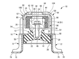
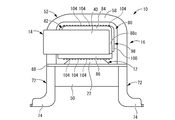
- FIG. 1 It is a longitudinal cross-sectional view of the vibration isolator as 1st embodiment of this invention, Comprising: II sectional drawing in FIG. It is another longitudinal cross-sectional view of the vibration isolator shown by FIG. 1, Comprising: The II-II sectional view in FIG.
- the top view of the vibration isolator shown by FIG. The front view of the vibration isolator shown by FIG.
- FIG. The rear view of the vibration isolator shown by FIG.
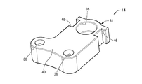
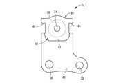
- the perspective view of the inner side bracket which comprises the vibration isolator shown by FIG.
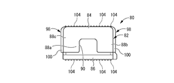
- the perspective view of the shock absorbing rubber member which comprises the vibration isolator shown by FIG. FIG. 11 is a plan view of the shock absorbing rubber member shown in FIG. 10.
- the bottom view of the shock absorbing rubber member shown by FIG. The left view of the shock absorbing rubber member shown by FIG. FIG. 14 is a cross-sectional view taken along line XIV-XIV in FIG. 11.
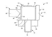
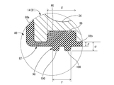
- the rear view of the shock absorbing rubber member shown by FIG. The principal part expanded cross-sectional view which shows the contact part vicinity of the inner side bracket and buffer rubber member in this embodiment.
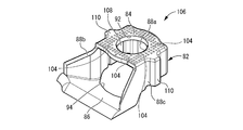
- the perspective view of the shock absorbing rubber member which comprises the vibration isolator as 2nd embodiment of this invention.
- the bottom view of the shock absorbing rubber member shown by FIG. The principal part expanded cross-sectional view which shows the contact part vicinity of the inner side bracket and buffer rubber member in this embodiment.
- FIGS. 1 to 6 show an engine mount 10 for an automobile as a first embodiment of a vibration isolator having a structure according to the present invention.
- the engine mount 10 has a structure in which an inner side bracket 14 and an outer side bracket 16 are attached to a mount body 12.
- the first attachment member 18 is attached to the power unit via the inner bracket 14 and the second attachment member 20 is attached to the vehicle body via the outer bracket 16 so that the power unit is prevented by the vehicle body. It is designed to be supported.
- the up and down direction refers to the up and down direction in FIG.
- the mount main body 12 has a structure in which the first mounting member 18 and the second mounting member 20 are connected by the main rubber elastic body 22.
- the first mounting member 18 is a highly rigid member having a substantially circular block shape, and is formed of a metal material such as iron or aluminum alloy, for example.
- a screw hole 24 extending in the vertical direction and opening in the upper end surface is formed at the radial center of the first mounting member 18.
- an annular flange portion 26 is integrally formed at the upper end portion of the first mounting member 18.
- the upper end surface of the first mounting member 18 includes the upper end surface of the flange portion 26 and is a large-diameter flat outer end surface 28 that extends in the direction perpendicular to the mount body axis.
- the second mounting member 20 has a thin, large-diameter, generally cylindrical shape, is formed of the same material as the first mounting member 18, and has high rigidity.
- the lower end part of the 2nd attachment member 20 is made into the annular bottom part 30 bent by the inner peripheral side.
- the first mounting member 18 and the second mounting member 20 are arranged so that the first mounting member 18 is spaced above the second mounting member 20 on the same central axis, and the main rubber elastic body 22 is elastically connected.
- the main rubber elastic body 22 has a thick and large-diameter substantially truncated cone shape, and a central recess 32 is formed in the large-diameter side end face. Further, the first mounting member 18 is inserted into the small diameter side end of the main rubber elastic body 22 and vulcanized and bonded, and the inner surface of the second mounting member 20 is attached to the outer peripheral surface of the large diameter side end. The peripheral surfaces are overlapped and vulcanized.
- the main rubber elastic body 22 is an integrally vulcanized molded product including the first mounting member 18 and the second mounting member 20.
- the inner side bracket 14 shown in FIGS. 7 to 9 is attached to the first attachment member 18 of the mount body 12 having the structure as described above.
- the inner side bracket 14 has a thick and substantially plate shape, and a bolt hole 34 penetrating vertically is formed on the base end side (left side portion in FIG. 1).
- the upper opening of the bolt hole 34 is enlarged in diameter, and a large-diameter recess 36 for accommodating the bolt head is formed.
- bolt holes 38 and 38 for attachment are formed at the front end portion of the inner side bracket 14 to serve as an attachment portion 40 to the power unit.
- a step 42 is formed on the lower surface of the inner bracket 14, and the base end side of the step 42 is thinner than the tip side by the height of the step 42.
- the inner side bracket 14 is overlaid on the outer end surface 28 of the first mounting member 18, and the step 42 is the outer peripheral surface of the flange portion 26 of the first mounting member 18. Is mounted in a state of being aligned with respect to.
- a concave groove 46 is formed on the outer peripheral surface of the inner bracket 14.
- a pair of concave grooves 46, 46 are formed on both side surfaces sandwiching the bolt hole 34 in the width direction (left-right direction in FIG. 8).
- the pair of concave grooves 46, 46 has a substantially constant groove width dimension (vertical dimension in FIG. 8) and a substantially constant groove depth dimension (horizontal dimension in FIG. 8).
- the inner bracket 14 is formed so as to extend linearly and continuously over the entire length in the plate thickness direction. As a result, the concave grooves 46 are open to both the upper and lower end surfaces of the inner bracket 14 on both sides in the length direction.
- a fixing bolt 48 inserted into the bolt hole 34 of the inner bracket 14 is screwed into the screw hole 24 of the first mounting member 18,
- the base end side of the inner side bracket 14 is fixed to the first mounting member 18, and the front end side of the inner side bracket 14 extends toward one side (right side in FIG. 1) in the direction perpendicular to the axis of the mount body 12. It is installed.
- the attachment part 40 at the front end side of the inner side bracket 14 is attached to the power unit by a fixing bolt inserted through the bolt hole 38.
- the outer bracket 16 is attached to the second attachment member 20 of the mount body 12.
- the outer side bracket 16 is configured to include a substantially cylindrical fitting portion 50 and a gate-shaped member 52 having a substantially gate shape.
- the portal member 52 is fixed so as to be overlaid on the top. Then, when the second mounting member 20 is press-fitted into the fitting portion 50, the outer bracket 16 is attached to the mount body 12 so that the portal member 52 covers the outside of the first mounting member 18. Is fixed.
- the gate-shaped member 52 has a pair of leg portions 54 and 54 that extend substantially in the vertical direction and are opposed to each other, and a beam portion 56 that connects the upper ends of the leg portions 54 and 54 to each other. And the lower end of a pair of leg parts 54 and 54 is piled up on the radial direction opposing part in the upper end surface of the fitting part 50, and the portal member 52 makes the upper side opening part of the fitting part 50 radial direction. It is arranged to straddle.
- the gate-shaped member 52 is integrally formed with a reinforcing rib 58 extending across the entire pair of leg portions 54 and 54 and the beam portion 56 at one end edge in the width direction (left-right direction in FIG. 1). ing. Further, an insertion hole 60 as a service hole for the fixing bolt 48 of the inner bracket 14 is formed in the central portion of the beam portion 56. An annular reinforcing rib 62 is also formed at the opening peripheral edge of the insertion hole 60.
- a side wall member 64 is disposed on the other side in the width direction of the portal member 52 (left side in FIG. 1), and an opening to the other side in the width direction of the portal member 52 is the side wall member 64. Covered.
- the side wall member 64 has a plate-like side wall portion 66 whose center portion bulges outward and is curved.
- the portal member 52 is provided with an annular plate-shaped contact portion 68, and this contact portion 68 is directly overlapped with the upper end surface of the fitting portion 50 over the entire circumference. It is fixed by welding. That is, the side wall portion 66 is integrally formed so as to rise from the outer peripheral edge portion at a part of the circumference of the annular plate-shaped contact portion 68.
- the abutting portion 68 is superimposed on the upper end surface of the fitting portion 50, so that the side wall portion 66 is arranged to rise upward at a part of the circumference of the fitting portion 50.
- both leg portions 54 and 54 of the portal member 52 are overlapped and fixed to the contact portion 68 of the sidewall member 64, and the portal member 52 is fixed to the sidewall portion 66 of the sidewall member 64.
- the opening edge on the other side in the width direction (left side in FIG. 1) is overlapped and fixed.
- the inner side bracket 14 is arranged in the gate-shaped member 52 in which one opening is covered with the side wall member 64 in a state of being inserted from the other opening.
- the inner bracket 14 is inserted from one opening of the gate-shaped member 52 and is bolted to the first mounting member 18 on the proximal end side, and the distal end side is the opening of the portal-shaped member 52.
- a plurality of connecting members 72 extending downward are attached to the fitting portion 50 of the outer side bracket 16 by being welded to the outer peripheral surface.
- An attachment portion 74 is formed at the lower end portion of each connecting member 72, and the outer side bracket 16 is fixed to the vehicle body using a bolt hole 76 of each attachment portion 74.
- the fitting portion 50, the portal member 52, the side wall member 64, and the connecting member 72 are fixed to each other by means such as welding, so that the outer side bracket 16 is configured.
- the first mounting member 18 and the second mounting member 20 are opposed to each other with a predetermined distance in the vertical direction in FIGS.
- the first stopper portion and the second stopper portion that are positioned are constituted by an inner side bracket 14 and an outer side bracket 16, respectively.
- the opposing surfaces of the inner side bracket 14 and the outer side bracket 16 are brought into contact with each other via a buffer rubber layer so that a stopper function is exhibited.
- the cushioning rubber layer is constituted by the cushioning rubber member 80 attached to the inner side bracket 14.
- the cushioning rubber member 80 has a substantially bag shape as shown in FIGS. 10 to 15 and is the base end side of the inner bracket 14 as shown in the enlarged view of the main part in FIG. It is attached so as to cover the insertion portion 81 to the outer side bracket 16.
- the shock absorbing rubber member 80 has a generally hollow rectangular bag shape as a whole, and a peripheral wall portion 82 that is superimposed on the outer peripheral surface (tip surface and both side surfaces) in the circumferential direction of the insertion portion 81 of the inner bracket 14.
- the upper wall portion 84 provided so as to cover the upper opening of the peripheral wall portion 82 and superimposed on the upper surface of the insertion portion 81, and the upper portion 84 of the insertion portion 81 provided so as to cover the lower opening of the peripheral wall portion 82.
- a lower wall portion 86 superimposed on the lower surface.
- the peripheral wall portion 82 is constituted by three side wall portions 88a, 88b, 88c each having a substantially plate shape.
- a through hole 90 is formed in the side wall portion 88 a overlapped with the distal end surface of the insertion portion 81, and this through hole 90 is used for removing air when the shock absorbing rubber member 80 is mounted or a spring of the shock absorbing rubber member 80. It functions as a characteristic adjustment.
- a through hole 92 is formed in the upper wall portion 84 at a position corresponding to the large-diameter recess 36 of the inner bracket 14, while an insertion portion 81 is first attached to the lower wall portion 86.
- An opening window 94 for directly overlapping the member 18 is formed.
- the side wall portions 88b and 88c of the shock absorbing rubber member 80 are integrally formed with inner protrusions 96 protruding inside the shock absorbing rubber member 80 on the inner surfaces thereof.
- the inward projections 96 and 96 are positioned and shaped so as to enter the respective concave grooves 46 and 46 formed in the inner side bracket 14 when the shock absorbing rubber member 80 is attached to the inner side bracket 14. ing.
- it is formed from the upper wall portion 84 to the lower end portion, and the shape and size with which the respective inner protrusions 96, 96 abut against the inner surfaces of the respective concave grooves 46, 46.
- the inner protrusions 96, 96 are assembled in the filled state with respect to the concave grooves 46, 46, respectively. Note that the end faces on both sides in the length direction (vertical direction) of the concave groove 46 in each of the inward projections 96, 96 are not superimposed on the inner surface of the concave groove 46, and the restraining force by the inner side bracket 14 Is a free surface that is not directly affected.
- the outer protrusions 98 that protrude outward from the shock absorbing rubber member 80 are formed on the outer surfaces of the side wall portions 88b and 88c at positions corresponding to the inner protrusions 96 on the inner surface. . Further, in the side wall portions 88 b and 88 c of the shock absorbing rubber member 80, a displacement regulating portion having a surface height smaller than that of the distal end surface of the outward projection 98 is provided at a portion where the concave groove 46 is removed on both sides in the width direction. .
- the displacement restricting portion is constituted by the portion of the side wall portions 88b and 88c that overlaps the surface of the inner side bracket 14 that is out of the both sides, and the displacement restricting portion is It is formed with a substantially constant thickness dimension.
- the separation distance between the outer surface of the inner bracket 14 and the front end surface of the outward projection 98 is ⁇ , If the separation distance between the outer surface of the inner bracket 14 and the outer surface of the displacement restricting portion, that is, the thickness dimension of the side wall portions 88b and 88c is ⁇ , ⁇ > ⁇ .
- each outer protrusion 98 has a dimension ⁇ (see FIG. 16) in the width direction of the groove 46 smaller than a dimension ⁇ (see FIG. 16) in the inner protrusion 96, so that the width direction of the groove 46 is reduced.
- the central portion extends linearly along the length direction of the groove 46 with a substantially constant cross-sectional shape.
- the outward protrusion 98 is constituted by two protrusions 100 and 100 extending in the length direction of the concave groove 46.
- the protrusion height dimension of the protrusion 100 is smaller than the protrusion height dimension of the inner protrusion 96, and the outer protrusion 98 is formed with a rubber volume smaller than the inner protrusion 96. .
- a large number of embossed protrusions 104 are formed on the upper surface of the upper wall portion 84 and the lower surface of the lower wall portion 86.
- the embossed protrusions 104 are preferably smaller in cross-sectional shape than the protrusions 100, so that the hitting sound at the time of contact is reduced.
- the shock-absorbing rubber member 80 having such a structure is covered with the insertion portion 81 of the inner side bracket 14 so that the inner protrusions 96 and 96 enter the grooves 46 and 46. Positioning is held.
- the buffer rubber member 80 is not bonded to the inner bracket 14 and is mounted using the elasticity of the buffer rubber member 80.
- the outer side bracket 16 and the inner side bracket 14 are arranged to face each other with a predetermined distance in a mounted state in a vehicle in which the shared support load of the power unit is applied in the vertical direction of the mount.
- an excessive external force such as a large vibration or impact load is exerted on the engine mount 10 due to a centrifugal force or a road surface input during cornering during traveling of the vehicle
- the inner side bracket 14 and the outer side bracket 16 are mutually cushioned with the cushioning rubber member 80.
- a shock absorber By striking via a shock absorber, a buffering stopper function is exhibited.
- the substantially middle portion in the length direction of the inner side bracket 14 and the contact portion 68 of the outer side bracket 16 are connected to the lower wall portion 86 of the shock absorbing rubber member 80.
- the stopper function in the bounce direction is exerted by abutting through the inner side, while the insertion portion 81 of the inner side bracket 14 and the beam portion 56 of the outer side bracket 16 are brought into contact with each other via the upper wall portion 84 of the shock absorbing rubber member 80.
- the stopper function in the rebound direction is exhibited by contact.
- the insertion part 81 of the inner side bracket 14 and the leg part 54 of the outer side bracket 16 are connected via the side wall part 88 of the shock absorbing rubber member 80.
- a stopper function in the vehicle longitudinal direction is exhibited.
- an inner protrusion 96 and an outer protrusion 98 are formed on the side wall 88 of the shock absorbing rubber member 80, and a large rubber volume is secured in cooperation with the inner and outer protrusions 96, 98 as a whole.
- a free surface is secured on both sides in the length direction of the inward projection 96, and a degree of freedom of deformation is advantageously given even when the inner projecting portion 96 is compressed and deformed in the press-contact direction between the contact surfaces. Thereby, a big energy absorption function and a damping function are exhibited, and the outstanding buffer performance by a soft spring characteristic can be obtained.
- the outer protrusion 98 having a smaller cross-sectional area than the inner protrusion 96 comes into contact first, the spring characteristics at the initial contact can be sufficiently softened, and the hitting sound and impact at the initial contact are further increased. It can be effectively suppressed.
- the portion where the concave groove 46 is deviated to both sides in the width direction is a displacement restricting portion, which is larger than the load region where only the stopper function by the above-described inner and outer protrusions 96, 98 is exhibited.
- the inner side bracket 14 and the outer side bracket 16 come into contact with each other through a displacement restricting portion that is thinner than the inner and outer protrusions 96 and 98, so that the relative displacement between the power unit and the vehicle body is increased. Can be reliably limited.
- the shock absorbing rubber member 80 is attached to the inner bracket 14 without being bonded, the shock absorbing action by the shock absorbing rubber member 80 is excellent in various stopper functions as described above. It can be more effectively exhibited under
- the inward projection 96 is assembled in contact with the bottom surface of the concave groove 46 from the beginning, the inner projection 96 strikes the bottom surface of the concave groove 46 when the stopper function is operated. Generation of hitting noise and impact can be avoided.
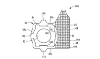
- FIGS. 17 and 18 show a shock-absorbing rubber member 106 constituting an engine mount as a vibration isolator as a second embodiment of the present invention.
- FIG. 19 shows an enlarged view of a main part in the assembled state of the buffer rubber member 106 and the inner side bracket 14. Since the basic structure of the engine mount of this embodiment is the same as that of the first embodiment, only the shock absorbing rubber member 106 is shown.
- the same members or parts as those of the first embodiment are denoted by the same reference numerals as those of the first embodiment in the drawings, and detailed description thereof is omitted.
- the inner protrusions 108 are formed on the inner surfaces of the side wall portions 88b and 88c of the shock absorbing rubber member 106, while the inner protrusions 108 on the outer surfaces of the side wall portions 88b and 88c,
- An outward projection 110 is formed at the corresponding position.
- the outward protrusion 110 is in the form of a single ridge extending along the length direction of the groove 46.
- the outward protrusion 110 has inclined surfaces on both sides in the width direction, and has a substantially trapezoidal cross-sectional shape from the side wall portions 88b and 88c of the shock absorbing rubber member 106. Therefore, the outward protrusion 110 of the present embodiment has a tapered shape in which the width dimension gradually decreases from the proximal end portion toward the distal end portion.
- the separation distance between the outer surface of the inner bracket 14 and the front end surface of the outward projection 110 is ⁇ ′, and the inner bracket If the distance between the outer surface 14 and the outer surface of the displacement restricting portion, that is, the thickness dimension of the side wall portions 88b and 88c is ⁇ ′, ⁇ ′> ⁇ ′. Further, the width dimension ⁇ ′ at the tip of the outer protrusion 110 is smaller than the width dimension of the inner protrusion 108 and the width dimension ⁇ ′ of the groove 46.
- the width dimension of the base end side of the outward protrusion 110 is also substantially smaller than the width dimension of the inward protrusion 108, and is formed with a size and a position that can be accommodated in the concave groove 46.
- the protruding height dimension of the outer protrusion 110 is larger than the protruding height dimension of the inner protrusion 108.
- an excellent buffer function can be obtained based on the elastic deformation of the inner protrusion 108 and the outer protrusion 110, and the buffer according to the present embodiment.
- the rubber member 106 can exert the same effect as that of the first embodiment, and the engine mount of this embodiment that employs the shock-absorbing rubber member 106 has various effects similar to those of the first embodiment. Can be demonstrated.
- the groove 46 is open on both sides in the length direction. However, even if the groove 46 itself is not open in the length direction, It is only necessary that both end portions in the length direction of 46 have a length that does not reach the end surface in the length direction of the groove 46 so that the groove 46 is formed as an end surface having a free surface.
- the inward protrusion and the outward protrusion in the buffer rubber layer have a structure in which the height dimension changes in the length direction of the groove, or are configured by a plurality of protrusions independent in the length direction of the groove. It is also possible to secure a large degree of freedom in tuning the stopper function according to the required characteristics.
- the inner protrusion is formed with a plurality of protrusions extending in the length direction of the groove, or the outer protrusion is formed with three or more protrusions extending in the length direction of the groove. It is also possible.
- the aspect of the engine mount is shown as the vibration isolator according to the present invention.
- the vibration isolator according to the present invention is not limited to the engine mount, and may be a body mount, a suspension support, a subframe mount or the like. Is also applicable.
- the specific shapes of the inner side bracket and the outer side bracket are not limited to those of the above-described embodiment.
- the outer side bracket can be configured without providing the side wall member 64.
- the inner side bracket and the outer side bracket are not essential, and the first stopper part and the second stopper part can be provided directly on the first mounting member and the second mounting member. It is.
- the stopper mechanism in the vertical direction can be configured by a member different from the stopper mechanism in the width direction (the vehicle longitudinal direction in the above embodiment).
- 10 Engine mount (vibration isolator), 14: Inner side bracket, 16: Outer side bracket, 18: First mounting member, 20: Second mounting member, 22: Rubber elastic body, 46: Concave groove, 80, 106: shock absorbing rubber member (buffer rubber layer), 81: insertion portion, 88b, 88c: side wall (displacement restricting portion), 96, 108: inward protrusion, 98, 110: outward protrusion, 100 : Ridge
Landscapes
- Engineering & Computer Science (AREA)
- Mechanical Engineering (AREA)
- General Engineering & Computer Science (AREA)
- Chemical & Material Sciences (AREA)
- Combustion & Propulsion (AREA)
- Transportation (AREA)
- Vibration Prevention Devices (AREA)
- Arrangement Or Mounting Of Propulsion Units For Vehicles (AREA)
Abstract
Description
Claims (11)
- 第一及び第二の取付部材が本体ゴム弾性体で連結されていると共に、それら第一及び第二の取付部材の相対的な変位方向で対向配置されて緩衝ゴム層を介して相互に当接する第一及び第二のストッパ部が設けられた防振装置において、
前記第一及び第二のストッパ部の少なくとも一方の他方に対する対向面に凹溝が設けられており、
該対向面に重ね合わされた前記緩衝ゴム層には該凹溝の内部へ入り込み且つ該凹溝の長さ方向の両側が自由端面とされた内方突部が形成されていると共に、
該緩衝ゴム層における該内方突部の形成部分において該凹溝から外方に向かって突出する外方突部が形成されている一方、
該対向面における該凹溝を幅方向両側に外れた部分を覆う該緩衝ゴム層には該外方突部の先端面よりも小さい表面高さの変位規制部が設けられている
ことを特徴とする防振装置。 - 前記緩衝ゴム層が、少なくとも前記内方突部の形成部分において前記ストッパ部に対して非接着で重ね合わされている請求項1に記載の防振装置。
- 前記凹溝の内面に対して前記内方突部が当接されている請求項1又は2に記載の防振装置。
- 前記凹溝の幅方向において、前記内方突部に比して前記外方突部の寸法が小さくされている請求項1~3の何れか1項に記載の防振装置。
- 前記外方突部が、前記凹溝の長さ方向に延びる複数の突条形態をもって形成されている請求項1~4の何れか1項に記載の防振装置。
- 前記外方突部が、前記内方突部よりも小さなゴムボリュームをもって形成されている請求項1~5の何れか1項に記載の防振装置。
- 前記外方突部が、先細形態をもって形成されている請求項1~6の何れか1項に記載の防振装置。
- 前記変位規制部が、前記対向面上において略一定の厚さ寸法で広がって形成されている請求項1~7の何れか1項に記載の防振装置。
- 前記凹溝が、前記ストッパ部における前記対向面の両端縁部間に亘って連続して延びており、該対向面の該両端縁部において該凹溝の長さ方向の両側がそれぞれ開放されている請求項1~8の何れか1項に記載の防振装置。
- 前記第一の取付部材にはインナ側ブラケットが取り付けられている一方、前記第二の取付部材には該インナ側ブラケットの外方を離隔して覆うアウタ側ブラケットが取り付けられており、該インナ側ブラケットと該アウタ側ブラケットとにおいて前記第一及び第二のストッパ部が構成されていると共に、該インナ側ブラケットに対して前記凹溝が形成されて前記緩衝ゴム層が設けられている請求項1~9の何れか1項に記載の防振装置。
- 前記アウタ側ブラケットにおいて前記第一の取付部材の外方を覆う門形部分が設けられている一方、前記インナ側ブラケットにおいて該アウタ側ブラケットの該門形部分に対して側方から差し入れられて該第一の取付部材に固定される差入部分が設けられており、前記緩衝ゴム層を構成する緩衝ゴム部材が該差入部分に被せられた状態で該インナ側ブラケットに装着されている請求項10に記載の防振装置。
Priority Applications (3)
| Application Number | Priority Date | Filing Date | Title |
|---|---|---|---|
| DE112014003425.8T DE112014003425B4 (de) | 2013-07-23 | 2014-07-01 | Schwingungsdämpfungsvorrichtung |
| US14/647,957 US9771996B2 (en) | 2013-07-23 | 2014-07-01 | Vibration-damping device |
| CN201480028913.2A CN105339703B (zh) | 2013-07-23 | 2014-07-01 | 隔振装置 |
Applications Claiming Priority (2)
| Application Number | Priority Date | Filing Date | Title |
|---|---|---|---|
| JP2013153015A JP6190651B2 (ja) | 2013-07-23 | 2013-07-23 | 防振装置 |
| JP2013-153015 | 2013-07-23 |
Publications (1)
| Publication Number | Publication Date |
|---|---|
| WO2015012072A1 true WO2015012072A1 (ja) | 2015-01-29 |
Family
ID=52393123
Family Applications (1)
| Application Number | Title | Priority Date | Filing Date |
|---|---|---|---|
| PCT/JP2014/067547 Ceased WO2015012072A1 (ja) | 2013-07-23 | 2014-07-01 | 防振装置 |
Country Status (5)
| Country | Link |
|---|---|
| US (1) | US9771996B2 (ja) |
| JP (1) | JP6190651B2 (ja) |
| CN (1) | CN105339703B (ja) |
| DE (1) | DE112014003425B4 (ja) |
| WO (1) | WO2015012072A1 (ja) |
Cited By (2)
| Publication number | Priority date | Publication date | Assignee | Title |
|---|---|---|---|---|
| JP2017065562A (ja) * | 2015-09-30 | 2017-04-06 | 倉敷化工株式会社 | エンジンマウント構造 |
| US10316925B2 (en) * | 2015-03-31 | 2019-06-11 | Bridgestone Corporation | Vibration damping device |
Families Citing this family (28)
| Publication number | Priority date | Publication date | Assignee | Title |
|---|---|---|---|---|
| US9541155B2 (en) * | 2013-08-09 | 2017-01-10 | Sumitomo Riko Company Limited | Mounting member for vibration damping device and vibration damping device using the same |
| JP6297400B2 (ja) * | 2014-04-30 | 2018-03-20 | 住友理工株式会社 | 防振装置 |
| JP6537958B2 (ja) * | 2015-11-19 | 2019-07-03 | 住友理工株式会社 | ブラケット付き防振装置 |
| DE102015122226B4 (de) * | 2015-12-18 | 2022-05-19 | Vibracoustic Se | Motorlager-Pendelstützen-Vorrichtung |
| FR3048474B1 (fr) * | 2016-03-04 | 2018-04-20 | Cooper Standard France | Dispositif d'amortissement de vibrations entre un premier element vibrant et un deuxieme element |
| JP6456339B2 (ja) | 2016-11-17 | 2019-01-23 | 東洋ゴム工業株式会社 | 防振装置 |
| JP6456340B2 (ja) * | 2016-11-17 | 2019-01-23 | 東洋ゴム工業株式会社 | 防振装置 |
| JP6456341B2 (ja) | 2016-11-17 | 2019-01-23 | 東洋ゴム工業株式会社 | 防振装置 |
| KR102479485B1 (ko) * | 2016-12-13 | 2022-12-19 | 현대자동차주식회사 | 분산된 스토퍼들을 가지는 자동차의 트랜스미션 마운트 |
| JP6783162B2 (ja) * | 2017-02-17 | 2020-11-11 | 住友理工株式会社 | ブラケット付き防振装置 |
| JP6807257B2 (ja) * | 2017-03-16 | 2021-01-06 | 住友理工株式会社 | 防振装置 |
| WO2018198412A1 (ja) * | 2017-04-25 | 2018-11-01 | 住友理工株式会社 | トルクロッド |
| US10576813B2 (en) * | 2017-08-14 | 2020-03-03 | Ford Global Technologies, Llc | Mounting bracket for a vehicle component and method of forming |
| JP6998809B2 (ja) * | 2018-03-26 | 2022-01-18 | 住友理工株式会社 | ゴムストッパ |
| JP6538231B1 (ja) * | 2018-03-30 | 2019-07-03 | 住友理工株式会社 | 筒形防振装置 |
| GB2590217B (en) * | 2018-06-19 | 2022-11-30 | Studco Building Systems Uk Ltd | Acoustic mount |
| CN109538687A (zh) * | 2018-11-07 | 2019-03-29 | 保定诺博汽车配件有限公司 | 悬置橡胶主簧及发动机悬置 |
| JP7361503B2 (ja) * | 2019-06-14 | 2023-10-16 | 株式会社プロスパイラ | 防振装置 |
| JP7072543B2 (ja) * | 2019-07-12 | 2022-05-20 | 本田技研工業株式会社 | 防振ユニット取付構造 |
| KR102881939B1 (ko) * | 2020-06-10 | 2025-11-05 | 현대자동차주식회사 | 자동차용 트랜스미션 마운트 |
| CN111688468A (zh) * | 2020-07-17 | 2020-09-22 | 中国汽车工程研究院股份有限公司 | 一种便调式的悬置装置 |
| DE102020126561B4 (de) * | 2020-10-09 | 2022-04-28 | Vibracoustic Se | Lager und Lageranordnung |
| FR3119654B1 (fr) * | 2021-02-09 | 2023-05-26 | Hutchinson | Support antivibratoire et véhicule comportant un tel support antivibratoire. |
| CN112776581B (zh) * | 2021-03-03 | 2023-04-07 | 四川建安工业有限责任公司 | 一种新能源汽车副车架悬置衬套装配结构 |
| JP7547289B2 (ja) * | 2021-06-29 | 2024-09-09 | 株式会社プロスパイラ | 防振装置 |
| CN115157558B (zh) * | 2022-06-21 | 2025-01-10 | 南京航梦企业咨询服务有限公司 | 一种音响模具用减震结构 |
| JP7794112B2 (ja) * | 2022-12-08 | 2026-01-06 | トヨタ自動車株式会社 | 内燃機関のマウント構造 |
| US12479251B2 (en) | 2024-02-06 | 2025-11-25 | Fca Us Llc | Rear lower isolator |
Citations (3)
| Publication number | Priority date | Publication date | Assignee | Title |
|---|---|---|---|---|
| JP2005106138A (ja) * | 2003-09-29 | 2005-04-21 | Tokai Rubber Ind Ltd | エンジンマウントの別体ゴムストッパ組付構造 |
| JP2006161973A (ja) * | 2004-12-08 | 2006-06-22 | Tokai Rubber Ind Ltd | エンジンマウント |
| JP2006177544A (ja) * | 2004-08-31 | 2006-07-06 | Tokai Rubber Ind Ltd | エンジンマウント |
Family Cites Families (11)
| Publication number | Priority date | Publication date | Assignee | Title |
|---|---|---|---|---|
| DE4322126C2 (de) | 1993-07-02 | 1995-06-29 | Metzeler Gimetall Ag | Elastisches Lager |
| JP2000220686A (ja) * | 1999-01-29 | 2000-08-08 | Bridgestone Corp | 防振装置 |
| JP3763384B2 (ja) * | 1999-09-29 | 2006-04-05 | 東洋ゴム工業株式会社 | エンジンマウント装置 |
| FR2831630B1 (fr) * | 2001-10-29 | 2004-01-30 | Hutchinson | Support antivibratoire hydraulique comportant un clapet de decouplage clipse |
| JP2009074653A (ja) * | 2007-09-21 | 2009-04-09 | Tokai Rubber Ind Ltd | 防振装置とその製造方法 |
| JP5355901B2 (ja) | 2008-02-21 | 2013-11-27 | 日立建機株式会社 | 防振支持装置 |
| JP5409513B2 (ja) | 2010-05-26 | 2014-02-05 | 東海ゴム工業株式会社 | 防振装置 |
| JP5909077B2 (ja) * | 2011-11-08 | 2016-04-26 | 東洋ゴム工業株式会社 | 防振ユニット |
| US9541155B2 (en) * | 2013-08-09 | 2017-01-10 | Sumitomo Riko Company Limited | Mounting member for vibration damping device and vibration damping device using the same |
| JP6388787B2 (ja) * | 2014-04-28 | 2018-09-12 | 株式会社ブリヂストン | 弾性ストッパ部材及び防振装置 |
| JP5941966B2 (ja) * | 2014-12-08 | 2016-06-29 | 住友理工株式会社 | 流体封入式防振装置 |
-
2013
- 2013-07-23 JP JP2013153015A patent/JP6190651B2/ja active Active
-
2014
- 2014-07-01 WO PCT/JP2014/067547 patent/WO2015012072A1/ja not_active Ceased
- 2014-07-01 DE DE112014003425.8T patent/DE112014003425B4/de active Active
- 2014-07-01 US US14/647,957 patent/US9771996B2/en active Active
- 2014-07-01 CN CN201480028913.2A patent/CN105339703B/zh active Active
Patent Citations (3)
| Publication number | Priority date | Publication date | Assignee | Title |
|---|---|---|---|---|
| JP2005106138A (ja) * | 2003-09-29 | 2005-04-21 | Tokai Rubber Ind Ltd | エンジンマウントの別体ゴムストッパ組付構造 |
| JP2006177544A (ja) * | 2004-08-31 | 2006-07-06 | Tokai Rubber Ind Ltd | エンジンマウント |
| JP2006161973A (ja) * | 2004-12-08 | 2006-06-22 | Tokai Rubber Ind Ltd | エンジンマウント |
Cited By (3)
| Publication number | Priority date | Publication date | Assignee | Title |
|---|---|---|---|---|
| US10316925B2 (en) * | 2015-03-31 | 2019-06-11 | Bridgestone Corporation | Vibration damping device |
| JP2017065562A (ja) * | 2015-09-30 | 2017-04-06 | 倉敷化工株式会社 | エンジンマウント構造 |
| WO2017056415A1 (ja) * | 2015-09-30 | 2017-04-06 | 倉敷化工株式会社 | エンジンマウント構造 |
Also Published As
| Publication number | Publication date |
|---|---|
| US9771996B2 (en) | 2017-09-26 |
| JP2015021613A (ja) | 2015-02-02 |
| DE112014003425T5 (de) | 2016-04-28 |
| US20150345583A1 (en) | 2015-12-03 |
| DE112014003425B4 (de) | 2025-03-20 |
| CN105339703B (zh) | 2017-03-29 |
| CN105339703A (zh) | 2016-02-17 |
| JP6190651B2 (ja) | 2017-08-30 |
Similar Documents
| Publication | Publication Date | Title |
|---|---|---|
| JP6190651B2 (ja) | 防振装置 | |
| JP4755147B2 (ja) | 防振装置 | |
| CN100394063C (zh) | 发动机安装件 | |
| US8523264B2 (en) | Windshield glass support structure | |
| JP6532367B2 (ja) | ブラケット付き筒形防振装置 | |
| US10807454B2 (en) | Vibration isolation structure | |
| JP6393200B2 (ja) | 防振装置および緩衝装置 | |
| JP4759527B2 (ja) | 制振装置 | |
| JP6595371B2 (ja) | 防振装置 | |
| US20190113099A1 (en) | Fluid-filled engine mounting apparatus | |
| JP6537958B2 (ja) | ブラケット付き防振装置 | |
| JP2009108912A (ja) | ダイナミックダンパ及びダイナミックダンパ構成部材の組合せ構造体 | |
| JP2011220434A (ja) | 防振装置 | |
| CN102686901A (zh) | 油压缓冲器 | |
| JP2005106192A (ja) | 筒型エンジンマウント | |
| JP5210933B2 (ja) | 液入り防振装置 | |
| JP7181399B2 (ja) | 防振装置 | |
| JP2009085300A (ja) | アッパーサポート | |
| JP3972292B2 (ja) | 車両用ショックアブソーバ | |
| JPH0789356A (ja) | 車両用防振マウントの支持構造 | |
| JP4252466B2 (ja) | ストッパ付防振装置 | |
| WO2023248672A1 (ja) | キャブマウント | |
| JPS6339462Y2 (ja) | ||
| KR20150026643A (ko) | 캐빈형 작업차의 방진 마운트 | |
| KR20110071239A (ko) | 차량용 서브프레임의 마운팅 부시 스토퍼 |
Legal Events
| Date | Code | Title | Description |
|---|---|---|---|
| WWE | Wipo information: entry into national phase |
Ref document number: 201480028913.2 Country of ref document: CN |
|
| 121 | Ep: the epo has been informed by wipo that ep was designated in this application |
Ref document number: 14828817 Country of ref document: EP Kind code of ref document: A1 |
|
| WWE | Wipo information: entry into national phase |
Ref document number: 14647957 Country of ref document: US |
|
| WWE | Wipo information: entry into national phase |
Ref document number: 112014003425 Country of ref document: DE |
|
| 122 | Ep: pct application non-entry in european phase |
Ref document number: 14828817 Country of ref document: EP Kind code of ref document: A1 |
|
| WWG | Wipo information: grant in national office |
Ref document number: 112014003425 Country of ref document: DE |