WO2015011897A1 - 車両周辺監視装置およびプログラム - Google Patents
車両周辺監視装置およびプログラム Download PDFInfo
- Publication number
- WO2015011897A1 WO2015011897A1 PCT/JP2014/003769 JP2014003769W WO2015011897A1 WO 2015011897 A1 WO2015011897 A1 WO 2015011897A1 JP 2014003769 W JP2014003769 W JP 2014003769W WO 2015011897 A1 WO2015011897 A1 WO 2015011897A1
- Authority
- WO
- WIPO (PCT)
- Prior art keywords
- image
- vehicle
- area
- horizontal line
- coordinate conversion
- Prior art date
- Legal status (The legal status is an assumption and is not a legal conclusion. Google has not performed a legal analysis and makes no representation as to the accuracy of the status listed.)
- Ceased
Links
Images




Classifications
-
- B—PERFORMING OPERATIONS; TRANSPORTING
- B60—VEHICLES IN GENERAL
- B60R—VEHICLES, VEHICLE FITTINGS, OR VEHICLE PARTS, NOT OTHERWISE PROVIDED FOR
- B60R1/00—Optical viewing arrangements; Real-time viewing arrangements for drivers or passengers using optical image capturing systems, e.g. cameras or video systems specially adapted for use in or on vehicles
- B60R1/20—Real-time viewing arrangements for drivers or passengers using optical image capturing systems, e.g. cameras or video systems specially adapted for use in or on vehicles
- B60R1/22—Real-time viewing arrangements for drivers or passengers using optical image capturing systems, e.g. cameras or video systems specially adapted for use in or on vehicles for viewing an area outside the vehicle, e.g. the exterior of the vehicle
- B60R1/23—Real-time viewing arrangements for drivers or passengers using optical image capturing systems, e.g. cameras or video systems specially adapted for use in or on vehicles for viewing an area outside the vehicle, e.g. the exterior of the vehicle with a predetermined field of view
-
- B—PERFORMING OPERATIONS; TRANSPORTING
- B60—VEHICLES IN GENERAL
- B60R—VEHICLES, VEHICLE FITTINGS, OR VEHICLE PARTS, NOT OTHERWISE PROVIDED FOR
- B60R11/00—Arrangements for holding or mounting articles, not otherwise provided for
- B60R11/04—Mounting of cameras operative during drive; Arrangement of controls thereof relative to the vehicle
-
- G—PHYSICS
- G06—COMPUTING OR CALCULATING; COUNTING
- G06T—IMAGE DATA PROCESSING OR GENERATION, IN GENERAL
- G06T1/00—General purpose image data processing
-
- G—PHYSICS
- G06—COMPUTING OR CALCULATING; COUNTING
- G06T—IMAGE DATA PROCESSING OR GENERATION, IN GENERAL
- G06T3/00—Geometric image transformations in the plane of the image
- G06T3/04—Context-preserving transformations, e.g. by using an importance map
- G06T3/047—Fisheye or wide-angle transformations
-
- G—PHYSICS
- G06—COMPUTING OR CALCULATING; COUNTING
- G06T—IMAGE DATA PROCESSING OR GENERATION, IN GENERAL
- G06T3/00—Geometric image transformations in the plane of the image
- G06T3/20—Linear translation of whole images or parts thereof, e.g. panning
-
- G—PHYSICS
- G06—COMPUTING OR CALCULATING; COUNTING
- G06T—IMAGE DATA PROCESSING OR GENERATION, IN GENERAL
- G06T7/00—Image analysis
- G06T7/60—Analysis of geometric attributes
-
- G—PHYSICS
- G06—COMPUTING OR CALCULATING; COUNTING
- G06V—IMAGE OR VIDEO RECOGNITION OR UNDERSTANDING
- G06V20/00—Scenes; Scene-specific elements
- G06V20/50—Context or environment of the image
- G06V20/56—Context or environment of the image exterior to a vehicle by using sensors mounted on the vehicle
- G06V20/58—Recognition of moving objects or obstacles, e.g. vehicles or pedestrians; Recognition of traffic objects, e.g. traffic signs, traffic lights or roads
- G06V20/586—Recognition of moving objects or obstacles, e.g. vehicles or pedestrians; Recognition of traffic objects, e.g. traffic signs, traffic lights or roads of parking space
-
- G—PHYSICS
- G06—COMPUTING OR CALCULATING; COUNTING
- G06V—IMAGE OR VIDEO RECOGNITION OR UNDERSTANDING
- G06V20/00—Scenes; Scene-specific elements
- G06V20/50—Context or environment of the image
- G06V20/56—Context or environment of the image exterior to a vehicle by using sensors mounted on the vehicle
- G06V20/588—Recognition of the road, e.g. of lane markings; Recognition of the vehicle driving pattern in relation to the road
-
- G—PHYSICS
- G08—SIGNALLING
- G08G—TRAFFIC CONTROL SYSTEMS
- G08G1/00—Traffic control systems for road vehicles
- G08G1/16—Anti-collision systems
-
- H—ELECTRICITY
- H04—ELECTRIC COMMUNICATION TECHNIQUE
- H04N—PICTORIAL COMMUNICATION, e.g. TELEVISION
- H04N23/00—Cameras or camera modules comprising electronic image sensors; Control thereof
- H04N23/60—Control of cameras or camera modules
- H04N23/63—Control of cameras or camera modules by using electronic viewfinders
-
- B—PERFORMING OPERATIONS; TRANSPORTING
- B60—VEHICLES IN GENERAL
- B60R—VEHICLES, VEHICLE FITTINGS, OR VEHICLE PARTS, NOT OTHERWISE PROVIDED FOR
- B60R2300/00—Details of viewing arrangements using cameras and displays, specially adapted for use in a vehicle
- B60R2300/30—Details of viewing arrangements using cameras and displays, specially adapted for use in a vehicle characterised by the type of image processing
- B60R2300/304—Details of viewing arrangements using cameras and displays, specially adapted for use in a vehicle characterised by the type of image processing using merged images, e.g. merging camera image with stored images
- B60R2300/305—Details of viewing arrangements using cameras and displays, specially adapted for use in a vehicle characterised by the type of image processing using merged images, e.g. merging camera image with stored images merging camera image with lines or icons
-
- B—PERFORMING OPERATIONS; TRANSPORTING
- B60—VEHICLES IN GENERAL
- B60R—VEHICLES, VEHICLE FITTINGS, OR VEHICLE PARTS, NOT OTHERWISE PROVIDED FOR
- B60R2300/00—Details of viewing arrangements using cameras and displays, specially adapted for use in a vehicle
- B60R2300/80—Details of viewing arrangements using cameras and displays, specially adapted for use in a vehicle characterised by the intended use of the viewing arrangement
- B60R2300/806—Details of viewing arrangements using cameras and displays, specially adapted for use in a vehicle characterised by the intended use of the viewing arrangement for aiding parking
-
- G—PHYSICS
- G06—COMPUTING OR CALCULATING; COUNTING
- G06T—IMAGE DATA PROCESSING OR GENERATION, IN GENERAL
- G06T2207/00—Indexing scheme for image analysis or image enhancement
- G06T2207/20—Special algorithmic details
- G06T2207/20112—Image segmentation details
-
- G—PHYSICS
- G06—COMPUTING OR CALCULATING; COUNTING
- G06T—IMAGE DATA PROCESSING OR GENERATION, IN GENERAL
- G06T2207/00—Indexing scheme for image analysis or image enhancement
- G06T2207/30—Subject of image; Context of image processing
- G06T2207/30248—Vehicle exterior or interior
- G06T2207/30252—Vehicle exterior; Vicinity of vehicle
-
- G—PHYSICS
- G08—SIGNALLING
- G08G—TRAFFIC CONTROL SYSTEMS
- G08G1/00—Traffic control systems for road vehicles
- G08G1/16—Anti-collision systems
- G08G1/168—Driving aids for parking, e.g. acoustic or visual feedback on parking space
Definitions
- a vehicle driver monitors the state of a road surface and the like from the vehicle interior by photographing a periphery including at least one road surface of the front and rear of the host vehicle and displaying the image in the vehicle interior.
- the present invention relates to a vehicle periphery monitoring device and a program.
- this type of vehicle periphery monitoring apparatus is installed with a back camera attached to the rear part of the vehicle, generates a virtual bird's-eye image by processing the original image of the rear of the vehicle photographed by the back camera, Display on the display in the passenger compartment.
- a conventional vehicle periphery monitoring device for example, only a road surface state may be displayed as a bird's-eye image on a display device in a vehicle interior. From such a bird's-eye image, the positional relationship between the vehicle and the road surface and information on the height direction are displayed. It is difficult for the vehicle driver to communicate, and there is a risk of giving the vehicle driver a sense of discomfort and pressure.
- An object of the present disclosure is to provide a vehicle periphery monitoring device and a program that can further suppress a sense of discomfort and pressure of a vehicle driver in a display image in a vehicle interior.
- an imaging unit that is attached to the host vehicle and captures a periphery including at least one road surface of the front and rear of the host vehicle, and an original image captured by the imaging unit, Using parameters that can calculate the edge position of the host vehicle and the horizontal line position with respect to the host vehicle, the ratios of the three partitioned areas partitioned in the vertical direction by the edge position and the horizontal line position are set in advance.
- An image processing unit that generates a virtual coordinate conversion image based on the original image by performing image correction including predetermined coordinate conversion so as to approach the ratio, and based on the coordinate conversion image generated by the image processing unit
- a vehicle periphery monitoring device including a display unit that displays a photographing screen in a predetermined display area in a vehicle interior.
- a program for causing a computer connected to the photographing unit and the display unit to function as the image processing unit is provided.
- each of the three partitioned areas in the coordinate conversion image is divided into an end area, an end position, and a horizontal line position, which are areas below the end position. If the road surface area is an area between, and the sky area is an area above the horizontal line position, it is possible to display a shooting screen in which these end area, road surface area, and sky area are distributed in a well-balanced manner at a predetermined ratio It becomes.
- the vehicle periphery monitoring device and the program according to the present disclosure not only the state of the road surface but also the edge position of the own vehicle and the horizontal line position with respect to the own vehicle can be easily understood as a coordinate conversion image on the display device in the vehicle interior. It can be shown to the driver, and the vehicle driver can intuitively recognize the positional relationship between the host vehicle and the road surface and information on the height direction from such a coordinate conversion image.
- the above parameters include external parameters indicating the position and orientation of the photographing unit, and the image processing unit performs, for example, camera calibration using this parameter, so that the vehicle on which the photographing unit is mounted (own vehicle) ),
- the edge position of the host vehicle in the original image and the horizontal line position with respect to the host vehicle can be calculated in advance. That is, even when the type (vehicle type) of the vehicle on which the photographing unit is mounted is different, it is possible to calculate in advance information about the edge position of the own vehicle and the horizontal line position with respect to the own vehicle in the original image.
- FIG. 1 is a block diagram illustrating the overall configuration of a vehicle periphery monitoring device
- FIG. 2 is an explanatory view illustrating the manner of attaching the camera to the host vehicle.
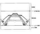
- FIG. 3 is an explanatory diagram illustrating each partition area in the image.
- FIG. 4 is a flowchart illustrating the contents of image processing performed by the vehicle periphery monitoring device.
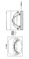
- FIG. 5A is an explanatory diagram illustrating synthesis of a simulated image (bumper image) in image processing
- FIG. 5B is an explanatory diagram illustrating synthesis of a simulated image (sky image) in image processing.
- a vehicle periphery monitoring device 1 is attached to a vehicle and photographs a periphery including at least one road surface in front of and behind the vehicle (hereinafter referred to as “own vehicle”).
- a camera 2 a display unit 4 that displays an image in a predetermined display area in the vehicle interior of the host vehicle, a control unit 6 that performs image correction (hereinafter referred to as “image processing”) including predetermined coordinate transformation described later,
- a storage unit 8 for storing information is provided.
- the camera 2 corresponds to an example of an imaging unit (or means) of the present disclosure
- the display unit 4 corresponds to an example of a display unit (or means)
- the control unit 6 corresponds to an example of an image processing unit (or means).
- the control unit 6 is a well-known electronic control device mainly composed of a microcomputer, and each unit of the vehicle periphery monitoring device 1 is controlled by the control unit 6.
- the control unit 6 may be prepared exclusively for controlling the vehicle periphery monitoring device 1 or may be a general-purpose device that performs control other than the vehicle periphery monitoring device 1. Moreover, you may comprise by the single control part 6, and the some control part 6 may function in cooperation.
- the camera 2 has a wide area around the vehicle including a bumper as a rear end portion of the own vehicle and a landscape at a position higher than the road surface along with the road surface behind the own vehicle by a plurality of fisheye lenses installed at the rear of the own vehicle. You can shoot. Further, the camera 2 has a control device, and when given an instruction for a cut-off angle of view from the control unit 6, a function of cutting out and providing a part of the original image at the angle of view according to the instruction is provided. I have.
- control unit 6 gives an instruction to the camera 2 to cut out the central part with less distortion of the original image, and the camera 2 cuts out the central part from the original image according to this instruction (hereinafter “ The camera image ”is provided to the control unit 6.
- the display unit 4 is a center display installed in or near the dashboard in the cabin of the host vehicle.
- the center display is generated by performing image processing on the camera image acquired from the camera 2 by the control unit 6. A shooting screen based on the obtained image (details will be described later) is displayed.
- the storage unit 8 includes, in addition to programs defining image processing performed by the control unit 6 and internal parameters specific to the camera 2 (ie, lens focal length, angle of view, number of pixels, etc.) in the world coordinate system. This is a non-volatile memory that stores external parameters indicating the position and orientation of the camera 2 (hereinafter referred to as “camera 2 mounting parameters”) and the like.
- the storage unit 8 stores information indicating the bumper position of the host vehicle and the horizontal line position with respect to the host vehicle (hereinafter referred to as “bumper / horizon line position information”) in the original image.
- the horizontal line position mainly indicates the boundary between the sky and the ground in the original image captured by the camera 2
- the bumper position mainly indicates the boundary between the ground and the host vehicle in the original image captured by the camera 2. I can say that.
- the bumper / horizontal line position information has, as viewed from the camera 2, the edge located at the end of the bumper at the rear of the vehicle (side extending in the vehicle width direction) as an edge, Bumper position information indicating in coordinates where each point constituting this edge position (ie, bumper position) is projected, and similarly a position indicating the horizontal direction when the camera 2 is the starting point ( That is, it is composed of horizontal line position information indicating in coordinates where the horizontal line position is projected in the original image.
- the camera 2 attachment parameters include position information representing the attachment position of the camera 2 in three dimensions (X, Y, Z) with respect to the host vehicle in the world coordinate system, and the attachment angle of the camera 2 by roll, pitch,
- the control unit 6 (or the control device of the camera 2) includes, for example, a camera calibration using the attachment parameters (and internal parameters) of the camera 2 to provide a bumper. -Horizontal line position information can be calculated in advance.
- the bumper / horizontal position information (and thus the mounting parameters of the camera 2 and the like) can be calculated in advance according to the shape of the vehicle (the host vehicle) on which the camera 2 is installed. Even when the type (vehicle type) of the vehicle is different, the bumper position of the own vehicle and the horizontal line position with respect to the own vehicle in the original image can be calculated in advance.
- an original image (or camera image) that can be acquired from the camera 2 and an image (a coordinate conversion image or a corrected image described later) generated by performing image processing by the control unit 6 are shown in FIG.
- the area below the bumper position is an area that mainly indicates the bumper at the rear of the vehicle, so it is called a bumper area (also called an end area)
- the area between the bumper position and the horizontal line position is Since it is an area mainly indicating the road surface state, it is referred to as a road surface area, and an area above the horizontal line position is referred to as an empty area because it is an area mainly indicating an empty landscape when there is no obstacle.
- control unit 6 When this process is started, the control unit 6 first reads the bumper / horizontal line position information from the storage unit 8 in S110, and acquires the original image from the camera 2 in subsequent S120.
- each of the three partitioned areas (bumpers) partitioned in the vertical direction by the bumper position and the horizontal line position in the original image is specified.
- a coordinate group (collection of a plurality of coordinates) indicating each of the area, the road surface area, and the sky area is specified.
- an instruction for cutting out the central portion of the original image with less distortion from the original image is supplied to the camera 2.
- the camera 2 Upon receiving this instruction from the control unit 6, the camera 2 provides the above-described camera image to the control unit 6.
- the ratio of each partition area is set in advance in the camera image based on the camera image acquired from the camera 2 in S140 and the coordinate group indicating each of the three partition areas specified in S130.
- image correction including predetermined coordinate conversion so as to approach the target ratio, a virtual coordinate conversion image based on the original image acquired in S110 is generated.
- image correction is performed so that at least the size of the bumper area and the sky area of each partitioned area approaches the target ratio within a range that does not exceed the size based on the target ratio. It has become.
- the target ratio is determined in advance by a sensory test or the like so that each divided area (bumper area, road area, sky area) is visually distributed in a coordinate conversion image (and a corrected image described later). It is a predetermined ratio.
- the mounting parameters of the camera 2 that is, position information and angle information related to the mounting of the camera 2 are used so that the road surface state can be easily recognized from the actual viewpoint from the camera 2.
- a known viewpoint conversion process is performed to convert the viewpoint to the selected viewpoint. Further, in the image correction, the aspect ratio of the image is changed as necessary in addition to the viewpoint conversion process.
- the image processing unit 6 permits the display unit 4 to display a shooting screen when the ratio of the three divided areas in the coordinate conversion image is equal to the target ratio (S160: YES) (S170).
- an image (bumper image) simulating the rear end (bumper) of the host vehicle is used so that the bumper area has a size based on the target ratio.
- first corrected image an image generated by performing a combining process for combining the bumper image with the coordinate conversion image in this way is displayed on the display unit 4.
- the display is permitted and the process is terminated.
- a bumper image of a corresponding size may be added to an area that is not large enough based on the target ratio in the bumper area, or all areas of the bumper area based on the target ratio are supported. You may join a bumper image of size.
- the bumper image may be any image as long as it simulates the rear end portion (bumper) of the host vehicle. For example, a simple image may be a black-colored image.
- an image (sky image) simulating the sky landscape so that the sky area has a size based on the target ratio. ) Is synthesized with at least a part of the sky region (see FIG. 5B), and the image (second image) generated by performing the synthesis process for synthesizing the sky image with the coordinate conversion image (or the first corrected image) in this way.
- the display unit 4 is allowed to display a shooting screen based on (corrected image)), and the process is terminated.
- a sky image of a corresponding size may be added to an area that is not large enough based on the target ratio in the sky area, or all areas of the sky area based on the target ratio are supported. You may join a sky image of size.
- the sky image may be any image as long as it simulates the sky landscape.
- a simple image may be an image filled with a blue color.
- the vehicle periphery monitoring device 1 includes the camera 2, the control unit 6, and the display unit 4.
- the camera 2 is attached to the host vehicle and photographs the vicinity of the vehicle including the road surface behind the host vehicle.
- the display unit 4 displays a shooting screen (including a shooting screen based on the corrected image) based on the coordinate conversion image generated by the control unit 6 in a predetermined display area in the vehicle interior.
- control unit uses the mounting parameters of the camera 2 that can calculate the edge position (bumper position) of the host vehicle and the horizontal line position with respect to the host vehicle in the original image taken by the camera 2, and the bumper position and A virtual coordinate conversion image based on the original image by performing image correction including predetermined coordinate conversion so that the ratio of each of the three divided areas divided in the vertical direction by the horizontal line position approaches a preset target ratio. Is generated.
- each of the three partitioned areas in the coordinate conversion image is divided into a bumper area that is a lower area than the bumper position, a road surface area that is an area between the edge position and the horizontal line position, and a horizontal line position.
- a bumper area that is a lower area than the bumper position As the sky area that is the upper area, it is possible to display a shooting screen in which the bumper area, the road surface area, and the sky area are distributed at a predetermined ratio in a balanced manner.
- the vehicle periphery monitoring device 1 not only the state of the road surface but also the bumper position of the own vehicle and the horizontal line position with respect to the own vehicle can be easily shown to the vehicle driver as a coordinate conversion image on the display unit 4 in the vehicle interior.
- the vehicle driver can intuitively recognize the positional relationship between the host vehicle and the road surface and information on the height direction from such a coordinate conversion image.
- the control unit 6 permits the display unit 4 to display a shooting screen when the ratio of each of the three partitioned areas in the coordinate conversion image is equal to the target ratio.
- the bumper position of the host vehicle and the horizontal line position with respect to the host vehicle are always kept constant, so that the vehicle driver is not made more uncomfortable. Can do.
- the control unit 6 synthesizes an image simulating the rear end (bumper) of the host vehicle with a coordinate conversion image when the bumper area is small with respect to the target ratio.
- the coordinate conversion image when the bumper position of the host vehicle is shifted downward with respect to the predetermined reference position, or when the end side position has disappeared, the end of the host vehicle is increased in order to improve the visibility.
- the bumper position of the host vehicle can be adjusted to a predetermined reference position.
- the control unit 6 is configured to synthesize an image simulating the sky landscape with the coordinate conversion image when the sky area is small with respect to the target ratio. That is, in the coordinate conversion image, when the horizontal line position with respect to the host vehicle is shifted upward with respect to a predetermined reference position, or when the horizontal line position has disappeared, an empty landscape is shown to improve visibility. By joining the simulated image, the horizontal line position with respect to the host vehicle can be adjusted to a predetermined reference position. As a result, it is possible to easily cope with a case where a display image in which a sky area is distributed with a desired balance cannot be obtained only by image correction including coordinate conversion, so that the vehicle driver can feel a sense of pressure. It can suppress suitably.
- this indication is not limited to the above-mentioned embodiment, and can be carried out in various modes in the range which does not deviate from the gist of this indication.
- the display unit 4 is configured by the center display of the host vehicle.
- the display unit 4 is not limited to this, and various displays such as a meter display and a head-up display. It can be constituted by a device.
- the camera 2 is installed in the rear part of the own vehicle, it is comprised by the rear view camera which image
- the present invention is not limited to this, and it may be configured by a front view camera that is installed in the front part of the host vehicle and captures the vehicle periphery including the road surface ahead of the host vehicle.
- the present invention is not limited to this.
- the ratio of each divided area is within an allowable range set in advance based on the target ratio, it is based on the coordinate conversion image. It may be permitted to display the shooting screen on the display unit 4.
- the shooting screen based on the coordinate conversion image is displayed. The display on the unit 4 may be permitted.
- the vehicle periphery monitoring device of the present disclosure made to achieve the above object includes an imaging unit, an image processing unit, and a display unit.
- photography part is attached to the own vehicle and image
- the display unit displays a shooting screen based on the coordinate conversion image generated by the image processing unit in a predetermined display area in the vehicle interior.
- the image processing unit uses the parameters that can calculate the edge position of the own vehicle and the horizontal line position with respect to the own vehicle in the original image taken by the photographing unit, and these edge position and horizontal line position.
- a virtual coordinate conversion image based on the original image is generated by performing image correction including predetermined coordinate conversion so that the ratio of each of the three divided areas divided in the vertical direction by the above approaches a preset target ratio To do.
- each of the three divided areas in the coordinate conversion image is divided into an end area which is an area below the end position, and a road surface area which is an area between the end position and the horizontal position.
- the sky area is an area above the horizontal line position, it is possible to display a photographing screen in which the end area, the road surface area, and the sky area are distributed at a predetermined ratio in a balanced manner.
- the above parameters include external parameters indicating the position and orientation of the photographing unit, and the image processing unit performs, for example, camera calibration using this parameter, so that the vehicle on which the photographing unit is mounted (own vehicle) ),
- the edge position of the host vehicle in the original image and the horizontal line position with respect to the host vehicle can be calculated in advance. That is, even when the type (vehicle type) of the vehicle on which the photographing unit is mounted is different, it is possible to calculate in advance information about the edge position of the own vehicle and the horizontal line position with respect to the own vehicle in the original image.
- the present disclosure can be distributed to the market as a program. Specifically, it is a program for causing a computer connected to the photographing unit and the display unit to function as the image processing unit.
- This program can be integrated into one or a plurality of computers to obtain the same effect as that achieved by the vehicle periphery monitoring device of the present disclosure.
- the program of the present disclosure may be stored in a ROM, flash memory, or the like incorporated in the computer, and loaded into the computer from the ROM, flash memory, or the like, or loaded into the computer via a network and used. May be.
- the above program may be used by being recorded on a recording medium of any form readable by a computer.
- the recording medium include a portable semiconductor memory (for example, a USB memory or a memory card (registered trademark)).
Landscapes
- Engineering & Computer Science (AREA)
- Physics & Mathematics (AREA)
- General Physics & Mathematics (AREA)
- Multimedia (AREA)
- Theoretical Computer Science (AREA)
- Mechanical Engineering (AREA)
- Signal Processing (AREA)
- Geometry (AREA)
- Computer Vision & Pattern Recognition (AREA)
- Closed-Circuit Television Systems (AREA)
- Image Processing (AREA)
- Image Analysis (AREA)
- Traffic Control Systems (AREA)
Abstract
Description
図1に示すように、本実施形態の車両周辺監視装置1は、車両に取り付けられて、その車両(以下「自車両」という)の前方および後方のうち少なくとも一方の路面を含む周辺を撮影するカメラ2と、自車両の車室内において所定の表示領域に画像を表示する表示部4と、後述する所定の座標変換を含む画像補正(以下「画像処理」という)を行う制御部6と、各種情報を記憶する記憶部8などを備えている。
次に、制御部6が実施する画像処理について、図4のフローチャートに沿って説明する。なお、本処理は、例えばエンジン始動に伴い、シフト位置センサ(非図示)から供給される検知情報に基づいてシフトレンジの検知を行い、シフトレンジがRに変更されると開始される。また、制御部6は、記憶部8に記憶されているプログラムに基づいて、本処理を実行するようになっている。
以上説明したように、車両周辺監視装置1は、カメラ2と、制御部6と、表示部4とを備える。カメラ2は、自車両に取り付けられて、その自車両の後方の路面を含む車両周辺を撮影する。表示部4は、制御部6によって生成された座標変換画像に基づく撮影画面(補正画像に基づく撮影画面を含む)を、車室内において所定の表示領域に表示する。
以上、本開示の実施形態について説明したが、本開示は上記実施形態に限定されるものではなく、本開示の要旨を逸脱しない範囲において、様々な態様にて実施することが可能である。
Claims (7)
- 自車両に取り付けられて、該自車両の前方および後方のうち少なくとも一方の路面を含む周辺を撮影する撮影部(2)と、
前記撮影部(2)によって撮影された原画像において、前記自車両の端辺位置および前記自車両に対する水平線位置を算出可能なパラメータを用いて、前記端辺位置および前記水平線位置によって上下方向に区画される3つの各区画領域の割合が予め設定された目標割合に近づくように所定の座標変換を含む画像補正を施すことにより、該原画像に基づく仮想的な座標変換画像を生成する画像処理部(6)と、
前記画像処理部(6)によって生成された座標変換画像に基づく撮影画面を、車室内において所定の表示領域に表示する表示部(4)と、
を備える車両周辺監視装置。 - 前記画像処理部(6)は、前記座標変換画像における前記3つの各区画領域の割合が前記目標割合と等しい場合に、前記表示部(4)による前記撮影画面の表示を許可する請求項1に記載の車両周辺監視装置。
- 前記座標変換画像における前記3つの各区画領域を、それぞれ、前記端辺位置より下側の領域である端部領域、前記端辺位置と前記水平線位置との間の領域である路面領域、前記水平線位置より上側の領域である空領域とし、
前記画像処理部(6)は、前記目標割合に対し、前記端部領域が少ない場合、前記自車両の端部を模擬した画像を前記座標変換画像に合成する請求項1または請求項2に記載の車両周辺監視装置。 - 前記座標変換画像における前記3つの各区画領域を、それぞれ、前記端辺位置より下側の領域である端部領域、前記端辺位置と前記水平線位置との間の領域である路面領域、前記水平線位置より上側の領域である空領域とし、
前記画像処理部(6)は、前記目標割合に対し、前記空領域が少ない場合、空の風景を模擬した画像を前記座標変換画像に合成する請求項1ないし請求項3のいずれか1項に記載の車両周辺監視装置。 - 請求項1ないし請求項4のいずれか1項に記載の前記撮影部(2)および前記表示部(4)に接続されるコンピュータを前記画像処理部(6)として機能させるためのプログラム。
- 請求項5に記載のプログラムを記憶する、コンピュータ読み取り可能な非一時的な記憶媒体。
- 前記水平線位置は、前記撮影部(2)によって撮影された原画像における空と地面の境界を示し、
前記端辺位置は、前記撮影部(2)によって撮影された原画像における前記地面と前記自車両の境界を示す、
請求項1ないし請求項4のいずれか一項に記載の車両周辺監視装置。
Priority Applications (3)
| Application Number | Priority Date | Filing Date | Title |
|---|---|---|---|
| DE112014003459.2T DE112014003459T5 (de) | 2013-07-26 | 2014-07-16 | Fahrzeugumgebungsüberwachungsvorrichtung und Programm |
| CN201480042246.3A CN105453558B (zh) | 2013-07-26 | 2014-07-16 | 车辆周边监视装置 |
| US14/906,838 US20160180179A1 (en) | 2013-07-26 | 2014-07-16 | Vehicle periphery monitoring apparatus and program |
Applications Claiming Priority (2)
| Application Number | Priority Date | Filing Date | Title |
|---|---|---|---|
| JP2013-155662 | 2013-07-26 | ||
| JP2013155662A JP5999043B2 (ja) | 2013-07-26 | 2013-07-26 | 車両周辺監視装置およびプログラム |
Publications (1)
| Publication Number | Publication Date |
|---|---|
| WO2015011897A1 true WO2015011897A1 (ja) | 2015-01-29 |
Family
ID=52392962
Family Applications (1)
| Application Number | Title | Priority Date | Filing Date |
|---|---|---|---|
| PCT/JP2014/003769 Ceased WO2015011897A1 (ja) | 2013-07-26 | 2014-07-16 | 車両周辺監視装置およびプログラム |
Country Status (5)
| Country | Link |
|---|---|
| US (1) | US20160180179A1 (ja) |
| JP (1) | JP5999043B2 (ja) |
| CN (1) | CN105453558B (ja) |
| DE (1) | DE112014003459T5 (ja) |
| WO (1) | WO2015011897A1 (ja) |
Families Citing this family (11)
| Publication number | Priority date | Publication date | Assignee | Title |
|---|---|---|---|---|
| US10152767B1 (en) * | 2016-12-15 | 2018-12-11 | The Mathworks, Inc. | Memory efficient on-chip buffering for projective transformation |
| KR102551099B1 (ko) | 2017-01-13 | 2023-07-05 | 엘지이노텍 주식회사 | 어라운드뷰 제공장치, 제공방법 및 이를 구비한 차량 |
| JP6964276B2 (ja) * | 2018-03-07 | 2021-11-10 | パナソニックIpマネジメント株式会社 | 表示制御装置、車両周辺表示システムおよびコンピュータプログラム |
| JP7104916B2 (ja) * | 2018-08-24 | 2022-07-22 | 国立大学法人岩手大学 | 移動物体検出装置および移動物体検出方法 |
| CN109353276B (zh) * | 2018-09-21 | 2022-02-11 | 上海豫兴电子科技有限公司 | 一种车载摄像头角度标定方法和标定装置 |
| CN109353275B (zh) * | 2018-09-21 | 2022-03-25 | 上海豫兴电子科技有限公司 | 一种车载摄像头角度标定贴膜及标定方法 |
| CN109774603A (zh) * | 2019-02-28 | 2019-05-21 | 上海豫兴电子科技有限公司 | 一种车载摄像头角度辅助标定方法和装置 |
| CN111652937B (zh) * | 2019-03-04 | 2023-11-03 | 广州汽车集团股份有限公司 | 车载相机标定方法和装置 |
| CN110285779A (zh) * | 2019-06-12 | 2019-09-27 | 智久(厦门)机器人科技有限公司 | 一种深度相机的角度误差补偿方法、装置、存储介质 |
| JP6692981B1 (ja) * | 2019-09-13 | 2020-05-13 | マレリ株式会社 | 表示装置及び表示方法 |
| CN112565629B (zh) * | 2020-12-03 | 2022-08-16 | 宁波视睿迪光电有限公司 | 一种图像处理方法、装置、系统、可读存储介质 |
Citations (5)
| Publication number | Priority date | Publication date | Assignee | Title |
|---|---|---|---|---|
| JP2002369186A (ja) * | 2001-06-07 | 2002-12-20 | Sony Corp | 車両後方画像表示装置、車両周囲画像表示方法 |
| JP2002374523A (ja) * | 2001-06-18 | 2002-12-26 | Matsushita Electric Ind Co Ltd | 監視システム |
| JP2003212041A (ja) * | 2002-01-25 | 2003-07-30 | Toyota Central Res & Dev Lab Inc | 車輌後方表示装置 |
| JP2010081245A (ja) * | 2008-09-25 | 2010-04-08 | Nissan Motor Co Ltd | 車両用表示装置および表示方法 |
| JP2010095086A (ja) * | 2008-10-15 | 2010-04-30 | Nissan Motor Co Ltd | 車両用表示装置および表示方法 |
Family Cites Families (6)
| Publication number | Priority date | Publication date | Assignee | Title |
|---|---|---|---|---|
| JP4286294B2 (ja) * | 2007-02-21 | 2009-06-24 | 三洋電機株式会社 | 運転支援システム |
| JP4924896B2 (ja) * | 2007-07-05 | 2012-04-25 | アイシン精機株式会社 | 車両の周辺監視装置 |
| US8395824B2 (en) * | 2008-07-17 | 2013-03-12 | Samsung Electronics Co., Ltd. | Method for determining ground line |
| JP5451497B2 (ja) * | 2010-04-08 | 2014-03-26 | パナソニック株式会社 | 運転支援表示装置 |
| JP5519479B2 (ja) * | 2010-11-29 | 2014-06-11 | パナソニック株式会社 | 運転支援表示装置 |
| JP5703255B2 (ja) * | 2012-04-27 | 2015-04-15 | 株式会社東芝 | 画像処理装置、画像処理方法およびプログラム |
-
2013
- 2013-07-26 JP JP2013155662A patent/JP5999043B2/ja not_active Expired - Fee Related
-
2014
- 2014-07-16 US US14/906,838 patent/US20160180179A1/en not_active Abandoned
- 2014-07-16 WO PCT/JP2014/003769 patent/WO2015011897A1/ja not_active Ceased
- 2014-07-16 CN CN201480042246.3A patent/CN105453558B/zh active Active
- 2014-07-16 DE DE112014003459.2T patent/DE112014003459T5/de not_active Ceased
Patent Citations (5)
| Publication number | Priority date | Publication date | Assignee | Title |
|---|---|---|---|---|
| JP2002369186A (ja) * | 2001-06-07 | 2002-12-20 | Sony Corp | 車両後方画像表示装置、車両周囲画像表示方法 |
| JP2002374523A (ja) * | 2001-06-18 | 2002-12-26 | Matsushita Electric Ind Co Ltd | 監視システム |
| JP2003212041A (ja) * | 2002-01-25 | 2003-07-30 | Toyota Central Res & Dev Lab Inc | 車輌後方表示装置 |
| JP2010081245A (ja) * | 2008-09-25 | 2010-04-08 | Nissan Motor Co Ltd | 車両用表示装置および表示方法 |
| JP2010095086A (ja) * | 2008-10-15 | 2010-04-30 | Nissan Motor Co Ltd | 車両用表示装置および表示方法 |
Also Published As
| Publication number | Publication date |
|---|---|
| DE112014003459T5 (de) | 2016-04-14 |
| US20160180179A1 (en) | 2016-06-23 |
| JP2015026989A (ja) | 2015-02-05 |
| CN105453558A (zh) | 2016-03-30 |
| CN105453558B (zh) | 2018-09-04 |
| JP5999043B2 (ja) | 2016-09-28 |
Similar Documents
| Publication | Publication Date | Title |
|---|---|---|
| JP5999043B2 (ja) | 車両周辺監視装置およびプログラム | |
| CN101978694B (zh) | 图像处理装置和方法、驾驶支持系统、车辆 | |
| US8947533B2 (en) | Parameter determining device, parameter determining system, parameter determining method, and recording medium | |
| US7365653B2 (en) | Driving support system | |
| US8018490B2 (en) | Vehicle surrounding image display device | |
| US11528453B2 (en) | Sensor fusion based perceptually enhanced surround view | |
| JP6099333B2 (ja) | 画像生成装置、画像表示システム、パラメータ取得装置、画像生成方法及びパラメータ取得方法 | |
| CN111819571B (zh) | 具有经调整适配的投影面的全景环视系统 | |
| JP6512016B2 (ja) | 車両用表示装置 | |
| US20080043113A1 (en) | Image processor and visual field support device | |
| JP6257978B2 (ja) | 画像生成装置、画像表示システム及び画像生成方法 | |
| JP2021516390A5 (ja) | ||
| JP2019529242A (ja) | 車両の車両周辺のバックミラー光景の提供方法 | |
| KR20170135952A (ko) | 차량의 주변 영역을 표시하기 위한 방법 | |
| JP2009151524A (ja) | 画像表示方法および画像表示装置 | |
| JP2007274377A (ja) | 周辺監視装置、プログラム | |
| JP7000383B2 (ja) | 画像処理装置および画像処理方法 | |
| CN107249934B (zh) | 无失真显示车辆周边环境的方法和装置 | |
| KR20220052172A (ko) | 서라운드뷰 모니터링 시스템 및 그 제공 방법 | |
| JP2014165810A (ja) | パラメータ取得装置、パラメータ取得方法及びプログラム | |
| US12080075B2 (en) | Method for generating an image of vehicle surroundings, and apparatus for generating an image of vehicle surroundings | |
| JP5271186B2 (ja) | 車両用画像表示装置 | |
| JP2007150658A (ja) | 車載周辺画像表示装置 | |
| JP6148896B2 (ja) | 画像生成装置及び画像生成方法 | |
| US20200231099A1 (en) | Image processing apparatus |
Legal Events
| Date | Code | Title | Description |
|---|---|---|---|
| WWE | Wipo information: entry into national phase |
Ref document number: 201480042246.3 Country of ref document: CN |
|
| 121 | Ep: the epo has been informed by wipo that ep was designated in this application |
Ref document number: 14829562 Country of ref document: EP Kind code of ref document: A1 |
|
| WWE | Wipo information: entry into national phase |
Ref document number: 14906838 Country of ref document: US |
|
| WWE | Wipo information: entry into national phase |
Ref document number: 112014003459 Country of ref document: DE |
|
| 122 | Ep: pct application non-entry in european phase |
Ref document number: 14829562 Country of ref document: EP Kind code of ref document: A1 |