WO2015005472A1 - 車体用振動減衰装置 - Google Patents
車体用振動減衰装置 Download PDFInfo
- Publication number
- WO2015005472A1 WO2015005472A1 PCT/JP2014/068559 JP2014068559W WO2015005472A1 WO 2015005472 A1 WO2015005472 A1 WO 2015005472A1 JP 2014068559 W JP2014068559 W JP 2014068559W WO 2015005472 A1 WO2015005472 A1 WO 2015005472A1
- Authority
- WO
- WIPO (PCT)
- Prior art keywords
- hydraulic
- vehicle body
- attenuator
- damping device
- vibration damping
- Prior art date
Links
Images


Classifications
-
- B—PERFORMING OPERATIONS; TRANSPORTING
- B62—LAND VEHICLES FOR TRAVELLING OTHERWISE THAN ON RAILS
- B62D—MOTOR VEHICLES; TRAILERS
- B62D24/00—Connections between vehicle body and vehicle frame
- B62D24/04—Vehicle body mounted on resilient suspension for movement relative to the vehicle frame
-
- F—MECHANICAL ENGINEERING; LIGHTING; HEATING; WEAPONS; BLASTING
- F16—ENGINEERING ELEMENTS AND UNITS; GENERAL MEASURES FOR PRODUCING AND MAINTAINING EFFECTIVE FUNCTIONING OF MACHINES OR INSTALLATIONS; THERMAL INSULATION IN GENERAL
- F16F—SPRINGS; SHOCK-ABSORBERS; MEANS FOR DAMPING VIBRATION
- F16F9/00—Springs, vibration-dampers, shock-absorbers, or similarly-constructed movement-dampers using a fluid or the equivalent as damping medium
- F16F9/10—Springs, vibration-dampers, shock-absorbers, or similarly-constructed movement-dampers using a fluid or the equivalent as damping medium using liquid only; using a fluid of which the nature is immaterial
- F16F9/14—Devices with one or more members, e.g. pistons, vanes, moving to and fro in chambers and using throttling effect
- F16F9/16—Devices with one or more members, e.g. pistons, vanes, moving to and fro in chambers and using throttling effect involving only straight-line movement of the effective parts
- F16F9/22—Devices with one or more members, e.g. pistons, vanes, moving to and fro in chambers and using throttling effect involving only straight-line movement of the effective parts with one or more cylinders each having a single working space closed by a piston or plunger
- F16F9/26—Devices with one or more members, e.g. pistons, vanes, moving to and fro in chambers and using throttling effect involving only straight-line movement of the effective parts with one or more cylinders each having a single working space closed by a piston or plunger with two cylinders in line and with the two pistons or plungers connected together
-
- F—MECHANICAL ENGINEERING; LIGHTING; HEATING; WEAPONS; BLASTING
- F16—ENGINEERING ELEMENTS AND UNITS; GENERAL MEASURES FOR PRODUCING AND MAINTAINING EFFECTIVE FUNCTIONING OF MACHINES OR INSTALLATIONS; THERMAL INSULATION IN GENERAL
- F16F—SPRINGS; SHOCK-ABSORBERS; MEANS FOR DAMPING VIBRATION
- F16F13/00—Units comprising springs of the non-fluid type as well as vibration-dampers, shock-absorbers, or fluid springs
- F16F13/005—Units comprising springs of the non-fluid type as well as vibration-dampers, shock-absorbers, or fluid springs comprising both a wound spring and a damper, e.g. a friction damper
- F16F13/007—Units comprising springs of the non-fluid type as well as vibration-dampers, shock-absorbers, or fluid springs comprising both a wound spring and a damper, e.g. a friction damper the damper being a fluid damper
-
- F—MECHANICAL ENGINEERING; LIGHTING; HEATING; WEAPONS; BLASTING
- F16—ENGINEERING ELEMENTS AND UNITS; GENERAL MEASURES FOR PRODUCING AND MAINTAINING EFFECTIVE FUNCTIONING OF MACHINES OR INSTALLATIONS; THERMAL INSULATION IN GENERAL
- F16F—SPRINGS; SHOCK-ABSORBERS; MEANS FOR DAMPING VIBRATION
- F16F9/00—Springs, vibration-dampers, shock-absorbers, or similarly-constructed movement-dampers using a fluid or the equivalent as damping medium
- F16F9/06—Springs, vibration-dampers, shock-absorbers, or similarly-constructed movement-dampers using a fluid or the equivalent as damping medium using both gas and liquid
-
- F—MECHANICAL ENGINEERING; LIGHTING; HEATING; WEAPONS; BLASTING
- F16—ENGINEERING ELEMENTS AND UNITS; GENERAL MEASURES FOR PRODUCING AND MAINTAINING EFFECTIVE FUNCTIONING OF MACHINES OR INSTALLATIONS; THERMAL INSULATION IN GENERAL
- F16F—SPRINGS; SHOCK-ABSORBERS; MEANS FOR DAMPING VIBRATION
- F16F9/00—Springs, vibration-dampers, shock-absorbers, or similarly-constructed movement-dampers using a fluid or the equivalent as damping medium
- F16F9/10—Springs, vibration-dampers, shock-absorbers, or similarly-constructed movement-dampers using a fluid or the equivalent as damping medium using liquid only; using a fluid of which the nature is immaterial
- F16F9/14—Devices with one or more members, e.g. pistons, vanes, moving to and fro in chambers and using throttling effect
- F16F9/16—Devices with one or more members, e.g. pistons, vanes, moving to and fro in chambers and using throttling effect involving only straight-line movement of the effective parts
-
- F—MECHANICAL ENGINEERING; LIGHTING; HEATING; WEAPONS; BLASTING
- F16—ENGINEERING ELEMENTS AND UNITS; GENERAL MEASURES FOR PRODUCING AND MAINTAINING EFFECTIVE FUNCTIONING OF MACHINES OR INSTALLATIONS; THERMAL INSULATION IN GENERAL
- F16F—SPRINGS; SHOCK-ABSORBERS; MEANS FOR DAMPING VIBRATION
- F16F9/00—Springs, vibration-dampers, shock-absorbers, or similarly-constructed movement-dampers using a fluid or the equivalent as damping medium
- F16F9/32—Details
- F16F9/56—Means for adjusting the length of, or for locking, the spring or damper, e.g. at the end of the stroke
Definitions
- the present invention relates to a vibration damping device for a vehicle body that damps vibrations of the vehicle body to improve riding comfort.
- a vibration damping device may be attached to the vehicle body.
- a vibration damping device for example, there is a hydraulic type device described in Patent Document 1.
- the hydraulic vehicle body vibration damping device disclosed in Patent Document 1 includes a hydraulic cylinder portion for generating damping force and a connecting rod portion coupled to a piston rod protruding from the hydraulic cylinder portion.
- the hydraulic cylinder section includes a hydraulic cylinder, a piston and a free piston that are movably fitted in the hydraulic cylinder, and a piston rod connected to the piston.
- the piston divides the hydraulic oil chamber in the hydraulic cylinder into two oil chambers.
- the piston is provided with a hydraulic oil passage that communicates the two oil chambers with each other and a check valve for generating a damping force that opens and closes the hydraulic oil passage.
- the piston rod penetrates one oil chamber and protrudes out of the hydraulic cylinder.
- the free piston partitions the inside of the hydraulic cylinder into a gas chamber filled with high-pressure gas and a hydraulic oil chamber.
- the hydraulic cylinder portion itself is directly fixed to one end portion in the left-right direction or the front-rear direction of the vehicle body.
- the piston is fixed to the other end in the left-right direction or the front-rear direction of the vehicle body via a piston rod and a connecting rod.
- the piston and the hydraulic cylinder move relative to each other due to the vibration of the vehicle body, and the hydraulic oil passes through the check valve of the piston to generate a damping force.
- Patent Document 1 Vehicles driven by passengers such as passenger cars and other automobiles are required to further improve the ride comfort.
- the conventional vehicle body vibration damping device disclosed in Patent Document 1 has a limit in improving the riding comfort of the vehicle. There are two reasons for this, as will be described later.
- the first reason is that, as described above, the hydraulic cylinder is directly fixed to one end of the vehicle body in the left-right direction or the front-rear direction, so that the length of the transmission path of vibration transmitted to the hydraulic cylinder and the piston are transmitted to the piston. This is because the length of the vibration transmission path is different. That is, the damping force generated in the hydraulic cylinder part directly acts on the vehicle body on the hydraulic cylinder side. On the other hand, a damping force acts on the piston-side vehicle body via a long non-rigid body composed of a piston rod and a connecting rod. This non-rigid object has a spring component and is elastically deformed.
- the non-rigid body is interposed in the middle of the piston-side vehicle body so that the damping force is reduced. For this reason, it is difficult to further improve the riding comfort of the vehicle because the vibration damping effect differs between the one end and the other end of the vehicle body.
- the second reason is that when the moving speed of the piston is extremely slow and the check valve does not open, the hydraulic oil flows through a so-called leak portion such as a seating portion of the check valve or a sliding portion of the piston.
- the hydraulic oil has viscous resistance. That is, in this case, a large damping force is generated for the moving speed of the piston due to the viscous resistance of the hydraulic oil passing through the leak portion.
- the vibration is not attenuated and the riding comfort of the vehicle is lowered.
- the case where the moving speed of the piston is remarkably slow is, for example, the initial operation of the piston or the case where the vehicle body gently vibrates so as not to be felt by the occupant.
- the present invention has been made to solve such a problem, and an object thereof is to provide a vehicle body vibration damping device that can further improve the riding comfort of a vehicle.
- a vibration damping device for a vehicle body includes a first hydraulic attenuator whose one end is attached to a predetermined first attachment position of the vehicle body, and the first hydraulic type.
- a second hydraulic attenuator that is connected to the other end of the attenuator via a connecting member, and an end opposite to the connecting member is attached to a predetermined second attachment position of the vehicle body;
- the first hydraulic attenuator and the second hydraulic attenuator are fitted into a hydraulic cylinder having an oil chamber filled with hydraulic oil, and movably fitted in the hydraulic cylinder.
- a piston partitioned into a first oil chamber and a second oil chamber; a piston rod connected to the piston and projecting from one end of the hydraulic cylinder; and movably fitted in the hydraulic cylinder;
- the cylinder is divided into a gas chamber filled with high-pressure gas and the oil chamber.
- a free piston that pressurizes the hydraulic oil in the oil chamber, a spring member that counteracts an axial force acting on the piston rod due to a difference in pressure receiving areas on both surfaces of the piston, the first oil chamber, and the first oil chamber A hydraulic oil passage communicating with the second oil chamber; a throttle provided in the hydraulic oil passage; the first hydraulic attenuator; the second hydraulic attenuator; and the connecting member; Are connected in a state aligned in the longitudinal direction, and one member of the hydraulic cylinder and the piston rod of the first hydraulic damper is connected to the connecting member, and the other member is the first member.
- the one of the hydraulic cylinder and the piston rod of the second hydraulic attenuator is connected to the connecting member, and the other member is set to the second mounting position. It can be attached .
- the first hydraulic attenuator and the second hydraulic attenuator according to the present invention generate a damping force when the piston and the hydraulic cylinder move relative to each other, respectively.
- the damping force generated by the first hydraulic attenuator acts directly on the first mounting position of the vehicle body from either one of the hydraulic cylinder and the piston rod.
- the damping force generated by the second hydraulic attenuator acts directly on the second mounting position of the vehicle body from either one of the hydraulic cylinder and the piston rod. For this reason, the vibration of the vehicle body is evenly damped in the first mounting portion and the second mounting portion of the vehicle body.
- the hydraulic oil filled in the hydraulic attenuator is viscous.
- a hydraulic attenuator having a hydraulic cylinder and a piston operates slightly from a so-called leak part such as a seating part of a check valve or a sliding part of the piston when the moving speed of the piston with respect to the hydraulic cylinder is low at the initial stage of operation. It is known that oil leaks. When the hydraulic oil leaks, a large damping force is generated for a low movement speed of the piston with a magnitude based on the magnitude of the viscous resistance of the hydraulic oil. The magnitude of the damping force is reduced as the moving distance of the piston relative to the hydraulic cylinder becomes relatively shorter.
- the movement amount of the piston with respect to the hydraulic cylinder for each hydraulic attenuator is 1 ⁇ 2 of the displacement amount between both ends of the vehicle body vibration damping device when the connecting member is a rigid body.
- the amount of movement of the piston relative to the hydraulic cylinder is the displacement between both ends of the vehicle vibration damping device. Match the quantity.
- the amount of hydraulic fluid that leaks when the moving speed of the piston relative to the hydraulic cylinder is low is reduced as compared with the conventional vibration damping device for a vehicle body that uses only one hydraulic attenuator.
- the damping force generated based on the viscous resistance of the hydraulic oil is reduced.
- the vibration of the vehicle body is gently attenuated at the beginning of operation.
- the first hydraulic attenuator and the second hydraulic attenuator function as so-called viscous dampers that consume energy by utilizing the viscous resistance of the hydraulic oil.
- the vehicle body vibration damping device according to the present invention can attenuate even high-frequency vibrations without depending on the direction in which the vibrations are propagated. Since this vehicle vibration attenuator has a plurality of hydraulic attenuators, it has a higher performance for attenuating vibrations in the high frequency range than a conventional vehicle attenuator having only one hydraulic attenuator. In addition, the vibration in the high frequency range is attenuated in a well-balanced manner. Therefore, according to the present invention, it is possible to provide a vehicle body vibration damping device that can further improve the riding comfort of the vehicle.
- FIG. 1 is a plan view showing a schematic configuration of a vehicle body vibration damping device according to a first embodiment of the present invention.
- FIG. 1 shows the vibration damping device for a vehicle body attached to the vehicle body.
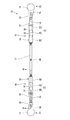
- FIG. 2A is a plan view showing a specific configuration of the vehicle body vibration damping device according to the first embodiment.
- FIG. 2B is a side view showing a specific configuration of the vehicle body vibration damping device according to the first exemplary embodiment.
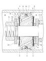
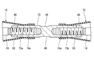
- 3 is a cross-sectional view taken along line III-III in FIG. 2A.
- FIG. 4 is an enlarged cross-sectional view of the piston portion of the hydraulic damper according to the first embodiment.
- FIG. 5 is a graph showing the relationship between the moving speed of the piston and the magnitude of the damping force.
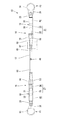
- FIG. 6A is a plan view showing a specific configuration of the vehicle body vibration damping device according to the second exemplary embodiment of the present invention.
- FIG. 6B is a side view showing a specific configuration of the vehicle body vibration damping device according to the second exemplary embodiment.
- 7 is a cross-sectional view taken along line VII-VII in FIG. 6A.
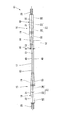
- FIG. 8A is a plan view showing a specific configuration of the vehicle body vibration damping device according to the third exemplary embodiment of the present invention.
- FIG. 8B is a side view showing a specific configuration of the vehicle body vibration damping device according to the third exemplary embodiment.
- FIG. 9 is a plan view showing the configuration of a vehicle body vibration damping device according to the fourth embodiment of the present invention.
- FIG. 9 illustrates the vibration damping device for a vehicle body attached to the vehicle body.
- FIG. 10 is a plan view showing a configuration of a vehicle body vibration damping device according to a fifth embodiment of the present invention.
- FIG. 10 shows the vibration damping device for a vehicle body attached to the vehicle body.
- FIG. 11 is a side view showing the configuration of the vehicle body vibration damping device according to the sixth embodiment of the present invention.
- FIG. 12 is an enlarged cross-sectional view showing a connecting portion between the first hydraulic damper and the third hydraulic damper according to the sixth embodiment.
- FIG. 13 is an enlarged cross-sectional view showing a connection portion between the second hydraulic damper and the third hydraulic damper according to the sixth embodiment.
- the vehicle body vibration damping device shown in this embodiment constitutes the invention according to claim 1, claim 2, claim 4 and claim 5.
- a vehicle 1 shown in FIG. 1 is driven by an occupant (not shown) and is, for example, a passenger car.
- the vehicle body 2 of the vehicle 1 is provided with a pair of left and right front wheels 3 and a pair of left and right rear wheels 4.
- This type of vehicle body 2 is formed of, for example, a monocoque body made of a high-strength steel plate or the like, and elastically deforms when an external force is applied during traveling, and vibrates, for example, in the left-right direction or the front-rear direction.
- the external force that generates this vibration includes a force applied to the vehicle body 2 when the front wheel 3 and the rear wheel 4 get over the unevenness during traveling, and a force received from a vibrating engine (not shown). Further, in this type of vehicle 1, the vehicle body 2 may vibrate even when the door of the passenger compartment (not shown) is closed. Such vibration of the vehicle body 2 may give a passenger discomfort.
- audio may be provided in the cabin of this type of vehicle 1.
- the frequency of the sound of the audio includes many high frequency components (about 500 Hz) compared to the frequency of vehicle body vibration during driving (about 40 Hz).
- the car body may resonate with the sound of the audio, and in such a case, the audio effect may be affected.
- a first vehicle body vibration damping device 11 is provided at the front portion of the vehicle body 2.
- a second vehicle body vibration damping device 12 is provided at the rear.
- the first vehicle body vibration damping device 11 and the second vehicle body vibration damping device 12 can be the same.
- One end portions of the first vehicle body vibration attenuating device 11 and the second vehicle body vibration attenuating device 12 are attached to a predetermined first attachment position P1 of the vehicle body 2, and the other end portion is a predetermined second portion.
- the attachment position P2 Even if there is a height difference between the first attachment position P1 and the second attachment position P2, the same effect can be obtained.
- the first vehicle body vibration attenuating device 11 and the second vehicle body vibration attenuating device 12 include a first hydraulic attenuator 15 and a second hydraulic attenuator 16 located on both sides in the longitudinal direction, A connecting rod 17 is provided between the first hydraulic attenuator 15 and the second hydraulic attenuator 16.
- the first hydraulic attenuator 15, the second hydraulic attenuator 16, and the connecting rod 17 are connected in a state of being aligned in the longitudinal direction, as will be described in detail later.
- these members are arranged on the same axis.
- the connecting rod 17 corresponds to a “connecting member” in the present invention.
- the first hydraulic attenuator 15 and the second hydraulic attenuator 16 are the same. As shown in FIGS. 2A and 2B, the first hydraulic attenuator 15 and the second hydraulic attenuator 16 are configured by a hydraulic cylinder 18 whose one end is attached to the suspension towers 13 and 14 as described later. ing. That is, the hydraulic cylinder 18 of the first hydraulic damper 15 is attached to the first attachment position P1 (the suspension tower 13 on the left side of the vehicle body). The hydraulic cylinder 18 of the second hydraulic attenuator 16 is attached to the second attachment position P2 (the suspension tower 14 on the right side of the vehicle body).
- the other end of the first hydraulic attenuator 15 and the other end of the second hydraulic attenuator 16 are formed by a piston rod 19 described later.
- the piston rod 19 of the first hydraulic damper 15 is connected to the piston rod 19 of the second hydraulic damper 16 via a connecting rod 17. That is, the piston rod 19 of the first hydraulic damper 15 and the piston rod 19 of the second hydraulic damper 16 are connected to each other via the connecting rod 17.
- the hydraulic cylinders 18 of the first hydraulic attenuator 15 and the second hydraulic attenuator 16 each have an oil chamber 21 filled with hydraulic oil, and as shown in FIG. 3, a cylinder tube made of a cylinder. 22, and a first lid member 23 and a second lid member 24 attached to the cylinder tube 22.
- the first lid member 23 closes one end (the left end in FIG. 3) of the cylinder tube 22.
- the first lid member 23 is welded to the cylinder tube 22 while being fitted in the cylinder tube 22.
- An attachment member 25 having a U-shaped cross section is welded to the first lid member 23.
- the mounting member 25 is fixed to a mounting bracket 26 (see FIG. 2A) provided at the upper ends of the suspension towers 13 and 14 by fixing bolts (not shown). That is, the hydraulic cylinder 18 according to this embodiment is attached to the suspension towers 13 and 14 via the attachment member 25 and the attachment bracket 26.
- the mounting bracket 26 is formed with rigidity that allows vibration of the vehicle body 2 to be transmitted to the hydraulic cylinder 18 side.
- the vehicle body vibration attenuating device includes a vehicle body having a rigid structure capable of transmitting vibration between the first attachment position P1 and the second attachment position P2.
- the second lid member 24 closes the other end of the cylinder tube 22 and movably supports a piston rod 19 described later.
- seal members 29 are provided for sealing the portions through which the piston rod 19 passes.
- the seal member 29 includes a first seal member 29 a and a second seal member 29 b located on the oil chamber 21 side, and a third seal member 29 c located outside the oil chamber 21.
- the second lid member 24 is fitted in the cylinder tube 22 and is fixed to the cylinder tube 22 together with the first spring seat 30 by circlips 27 and 28.
- a piston 31 and a free piston 32 are movably fitted.
- the piston 31 is formed in a circular cross section that fits into the cylinder tube 22, and partitions the oil chamber 21 in the hydraulic cylinder 18 into a first oil chamber 33 and a second oil chamber 34.
- a seal member 35 that seals between the inner periphery of the cylinder tube 22 is provided on the outer periphery of the piston 31.
- an O-ring 35 a is disposed on the inner peripheral side of the seal member 35. The O-ring 35 a urges the seal member 35 to expand radially outward, and seals the gap between the inner peripheral surface of the seal member 35 and the outer peripheral portion of the piston 31.
- the base end portion of the piston rod 19 passes through the axial center portion of the piston 31.
- the piston 31 is fixed to a distal end portion of the piston rod 19 by a fixing nut 39 together with valve bodies 37 and 38 of a piston valve 36, a second spring seat 31a, and a washer 31b, which will be described later.
- the first oil chamber 33 is formed between the piston 31 and a free piston 32 described later.
- the second oil chamber 34 is formed between the piston 31 and the second lid member 24.
- the free piston 32 is disposed on one end side of the cylinder tube 22 where the first lid member 23 is located, and partitions the hydraulic cylinder 18 into an oil chamber 21 and a gas chamber 40.
- An O-ring 32 a is fitted on the outer periphery of the free piston 32.
- the O-ring 32 a seals between the gas chamber 40 and the oil chamber 21.
- the gas chamber 40 is filled with high-pressure N 2 gas. For this reason, the hydraulic oil in the oil chamber 21 is pressurized by the free piston 32.
- a compression coil spring 41 is inserted between the piston 31 and the second lid member 24 in a compressed state.
- One end portion of the compression coil spring 41 on the second lid member 24 side is in contact with the first spring seat 30, and the other end portion is in contact with the second spring seat 31a.
- the piston rod 19 passes through the central portion of the compression coil spring 41.
- the piston 31 is biased by the spring force of the compression coil spring 41 in the direction in which the hydraulic dampers 15 and 16 are contracted (leftward in FIG. 3).
- the compression coil spring 41 is for canceling the axial force acting on the piston rod 19 due to the difference in pressure receiving area on both surfaces of the piston 31. This axial force is generated because the pressure receiving area on the second oil chamber 34 side is smaller than the pressure receiving area on the first oil chamber 33 side of the piston 31, and the piston rod 19 is connected to the hydraulic dampers 15, 16. Press in the direction that extends.
- the compression coil spring 41 constitutes a “spring member” in the present invention.
- the free lengths of the first hydraulic attenuator 15 and the second hydraulic attenuator 16 are the lengths in a state in which the axial force described above is balanced by being canceled out by the spring force of the compression coil spring 41. That's it.
- the pressure of N 2 gas is adjusted so that the free length matches the mounting dimension to the vehicle body 2. Since the free length matches the mounting dimension to the vehicle body 2 in this manner, the work of mounting the first vehicle body vibration damping device 11 and the second vehicle body vibration damping device 12 to the vehicle body 2 becomes easy.
- the initial load becomes zero when the first vehicle body vibration damping device 11 and the second vehicle body vibration damping device 12 are attached to the vehicle body 2. For this reason, the first hydraulic attenuator 15 and the second hydraulic attenuator 15 contract with good responsiveness, and a damping force can be generated.
- the piston valve 36 provided on the piston 31 has a structure equivalent to that used in a shock absorber for the suspension device of the vehicle 1. As shown in FIG. 4, the piston valve 36 includes a first throttle 42 and a second throttle 43.
- the first throttle 42 is provided in a first hydraulic oil passage 44 that penetrates the piston 31.
- the second throttle 43 is provided in a second hydraulic oil passage 45 that penetrates the piston 31.
- the end of the first hydraulic oil passage 44 on the second oil chamber 34 side is formed by an annular recess 44a.
- the first throttle 42 constitutes a check valve that closes the recessed portion 44 a and includes a plurality of disc-shaped valve bodies 37. These valve bodies 37 are attached to the piston rod 19 in a state where they are pressed against the outer peripheral edge of the recessed portion 44a by their own spring force. That is, the inner peripheral portion of the valve body 37 is pressed toward the piston 31 by the first spacer 46 provided on the piston rod 19 in a state where the inner periphery of the valve body 37 is fitted to the piston rod 19 and the nut 39 is tightened.
- the first spacer 46 is attached to the piston rod 19 in a state in which movement in the direction away from the piston 31 together with the second spring seat 31a is restricted.
- the valve element 37 of the first throttle 42 is pressed against the opening on the second oil chamber 34 side in the first hydraulic oil passage 44 with a predetermined initial load, and closes the opening. For this reason, the valve element 37 opens when the hydraulic pressure in the first oil chamber 33 is higher than the initial load of the valve element 27.
- the end of the second hydraulic oil passage 45 on the first oil chamber 33 side is formed by an annular recess 45a.
- the second throttle 43 constitutes a check valve that closes the recessed portion 45a, and includes a plurality of disc-shaped valve bodies 38. These valve bodies 38 are attached to the piston rod 19 in a state where they are pressed against the outer peripheral edge of the recessed portion 45a by their own spring force. That is, the inner peripheral portion of the valve body 38 is pressed toward the piston 31 by the second spacer 47 provided on the piston rod 19 in a state where the inner periphery of the valve body 38 is fitted to the piston rod 19 and the nut 39 is tightened.
- the second spacer 47 is attached to the piston rod 19 in a state where movement in a direction away from the piston 31 together with the washer 31b is restricted.
- the valve body 38 is deformed and pressed against the outer peripheral edge of the recessed portion 45a with a predetermined initial load.
- the valve body 38 of the second throttle 43 is pressed against the opening on the first oil chamber 33 side in the second hydraulic oil passage 45 with a predetermined initial load, and closes the opening. For this reason, the valve body 38 opens when the hydraulic pressure in the second oil chamber 34 is higher than the initial load of the valve body 38.
- the thickness and the number of valve bodies 37 of the first throttle 42 and the valve body 38 of the second throttle 43 are determined by the magnitude of the damping force generated by the first hydraulic attenuator 15 and the second hydraulic attenuator 16. It is decided based on the size. When the spring force of these valve bodies 37 and 38 increases, the generated damping force increases.
- the magnitude of the damping force of the first vehicle body vibration damping device 11 and the second vehicle body vibration damping device 12 according to this embodiment is equivalent to the magnitude of the damping force when only one hydraulic attenuator is used. is there.
- the tip of the piston rod 19 penetrates through the second lid member 24 and protrudes out of the cylinder tube 22, and is coupled to the end of the connecting rod 17 by a screw.
- the connecting rod 17 is formed of a metal round bar.
- Female threads 17 a for attaching the first hydraulic damper 15 and the second oil chamber damper 16 are formed at both ends of the connecting rod 17.
- the connecting portion between the piston rod 19 and the connecting rod 17 employs a structure in which a male screw 19 a formed on the piston rod 19 is screwed onto the female screw 17 a of the connecting rod 17 and is tightened by a lock nut 48.
- a male screw 19 a formed on the piston rod 19 is screwed onto the female screw 17 a of the connecting rod 17 and is tightened by a lock nut 48.
- the flat surface 49 is formed in parallel with each other at two locations on the outer peripheral portion of the connecting rod 17. The above-described operation of tightening the lock nut 48 is performed in a state where the rotation of the connecting rod 17 is restricted by engaging a tool with the flat surface 49.
- the joint portion between the piston rod 19 and the connecting rod 17 is covered with a rubber boot 50 that connects the connecting rod 17 and the cylinder tube 22 as shown in FIG.
- the rubber boot 50 is for preventing muddy water and dust from adhering to the piston rod 19 and is formed in a conical cylinder shape.
- One end of the rubber boot 50 is fixed to the outer peripheral surface of the cylinder tube 22, and the other end is fixed to the outer peripheral surface of the connecting rod 17.
- first, the first vehicle body vibration damping device 11 and the second vehicle body vibration damping device 12 are put into a temporarily assembled state.
- This temporarily assembled state means that, for example, one end of the connecting rod 17 is coupled to the piston rod 19 of the first hydraulic attenuator 15, and the second hydraulic attenuator is connected to the other end of the connecting rod 17.
- the piston rod 19 is temporarily screwed in.
- the piston rod 19 and the connecting rod 17 of the first hydraulic damper 15 are coupled by tightening a lock nut 48 in this temporarily assembled state.
- the lock nut 40 is tightened, the tool is engaged with the flat surface 49 of the connecting rod 17 to restrict the rotation of the connecting rod 17.
- the mounting member 25 provided in the first hydraulic attenuator 15 described above is temporarily mounted on the mounting bracket 26 of the suspension tower 13 by a fixing bolt (not shown). Then, the screwing amount between the other end of the connecting rod 17 and the piston rod 19 of the second hydraulic damper 16 is adjusted, and the mounting member 25 of the second hydraulic damper 16 is attached to the other suspension tower 14.
- the bracket 26 is temporarily attached with fixing bolts.
- the total length of the first vehicle body vibration attenuating device 11 and the second vehicle body vibration attenuating device 12 is adjusted in accordance with the distance between the pair of left and right suspension towers 13 and 14.
- the lock nut 48 of the second hydraulic attenuator 16 is tightened in a state where the first vehicle body vibration damping device 11 and the second vehicle body vibration damping device 12 are held by the vehicle body 2.
- the operation of tightening the lock nut 48 is performed while restricting the rotation of the connecting rod 17 by engaging a tool with the flat surface 49 of the connecting rod 17.
- the piston rod 19 of the second hydraulic damper 16 is coupled to the connecting rod 17.
- the first hydraulic damper 15 and the second hydraulic damper 16 are fixed to the mounting bracket 26 with fixing bolts, thereby fixing the first vehicle body vibration damping device 11. And the work of attaching the second vehicle body vibration damping device 12 to the vehicle body 2 is completed.
- the first vehicle body vibration attenuating device 11 and the second vehicle body vibration attenuating device 12 thus configured have a first hydraulic attenuator 15 and a second hydraulic attenuator 16 at both ends, respectively.
- the first hydraulic damper 15 and the second hydraulic damper 15 generate a damping force when the hydraulic cylinder 18 and the piston 31 move relative to each other.
- the damping force generated by the first hydraulic attenuator 15 directly acts on the first mounting position P1 of the vehicle body 2 from the hydraulic cylinder 18.
- the damping force generated by the second hydraulic damper 16 directly acts on the second mounting position P2 of the vehicle body 2 from the hydraulic cylinder 18. For this reason, the vibration of the vehicle body 2 is equally damped at the first mounting position P1 and the second mounting position P2.
- the piston 31 When the distance between the pair of left and right suspension towers 13, 14 changes due to the vibration of the vehicle body 2, the piston 31 is in relation to the cylinder tube 22 in the first hydraulic damper 15 and the second hydraulic damper 16. It moves in the axial direction (the left-right direction of the vehicle body 2).
- the first hydraulic attenuator 15 and the second hydraulic attenuator 16 all of the seal members 29 that are elastically deformable facing the oil chamber 21 in which the hydraulic oil is pressurized by high-pressure N 2 gas, The O-ring 35 of the piston 31 and the O-ring 32a of the free piston 32 are kept in a state where they cannot be elastically deformed any further.
- the hydraulic oil flows between the first oil chamber 33 and the second oil chamber 34 with good responsiveness. Even when the moving amount of the piston 31 is several tens of microns, the damping force is generated with high responsiveness.
- the leakable gap is a gap through which hydraulic oil can flow between the first oil chamber 33 and the second oil chamber 34.
- This leakable gap is hereinafter referred to as a leak portion.
- the leak parts of the first hydraulic attenuator 15 and the second hydraulic attenuator 16 according to this embodiment are the leak part in the range surrounded by the two-dot chain line A in FIG. This is a leak portion in a range surrounded by a two-dot chain line B.
- the leak portion indicated by a two-dot chain line A is referred to as a first leak portion A
- the leak portion indicated by a two-dot chain line B is referred to as a second leak portion B.
- the first leak portion A is a gap serving as a clearance between the piston 31 and the cylinder tube 22.
- the second leak portion B is a gap between the valve bodies 37 and 38 of the first throttle 42 and the second throttle 43 and the outer peripheral edges of the recessed portions 44 a and 45 a of the piston 31.
- the hydraulic oil has a viscosity. For this reason, immediately after the piston 31 starts moving and before the valve bodies 37 and 38 are opened, the hydraulic oil leaks through the first leak portion A and the second leak portion B, thereby operating. A damping force is generated with a magnitude corresponding to the magnitude of the viscous resistance of the oil.
- the magnitude of the damping force immediately after the start of the movement of the piston 31 changes substantially in proportion to the moving speed of the piston 31, as shown in FIG.
- the damping force based on the viscous resistance of the hydraulic oil is simply referred to as a low-speed damping force.
- the change in the damping force of the vibration damping device for a vehicle body according to this embodiment is shown by a solid line, and the change in the damping force when only one hydraulic attenuator is used is shown by a broken line.
- a change in damping force when two hydraulic attenuators are used in parallel is indicated by a two-dot chain line.
- To use two hydraulic dampers in parallel means that two hydraulic dampers are provided between the left and right suspension towers 13 and 14, respectively.
- the movement amount of the piston 31 of the first hydraulic attenuator 15 and the second hydraulic attenuator 16 according to this embodiment is the same as that of the first vehicle body vibration attenuating device 11 and the second vehicle body vibration attenuating device 12. It becomes half the amount of displacement between both ends. Therefore, as shown by the solid line in FIG. 5, the magnitude of the low-speed damping force of the first vehicle body hydraulic vibration damping device 11 and the second vehicle body hydraulic vibration damping device 12 according to this embodiment is Compared to a conventional device (shown by a broken line in FIG. 5) that uses only one hydraulic attenuator, if the moving speed of the piston 31 is the same, it is 1 ⁇ 2.
- the moving speed of the piston 31 of the first hydraulic attenuator 15 and the second hydraulic attenuator 16 is higher than when only one hydraulic attenuator is used.
- the flow rate is extremely low, the amount of hydraulic oil that leaks through the first leak portion A and the second leak portion B is reduced, and the damping force that is generated based on the viscous resistance of the hydraulic oil is reduced.
- the vibration of the vehicle body 2 is gently damped when the moving speed of the piston 31 of the first hydraulic attenuator 15 and the second hydraulic attenuator 16 is low, such as in the initial stage of operation.
- the moving speed of the piston 31 when shifting to the valve region L3 in the first vehicle body vibration damping device 11 and the second vehicle body vibration damping device 12 is one hydraulic damper. Only when it is used (indicated by a broken line in FIG.
- the moving speed of the piston 31 is higher. This means that the ride comfort is improved by reducing the increase in damping force at the initial stage of operation. After shifting to the valve region L3, the rate at which the magnitude of the damping force increases is significantly smaller than the rate at which the moving speed of the piston 31 increases.
- the first hydraulic attenuator 15 and the second hydraulic attenuator 16 use the viscous resistance of the hydraulic oil stored in the first oil chamber 33 and the second oil chamber 34. It also functions as a so-called viscous damper that consumes energy. For this reason, the first vehicle body vibration attenuating device 11 and the second vehicle body vibration attenuating device 12 according to this embodiment attenuates even high-frequency vibrations without depending on the direction of vibration propagation. be able to.
- first vehicle body vibration attenuating device 11 and the second vehicle body vibration attenuating device 12 include a first hydraulic attenuator 15 and a second hydraulic attenuator 16, respectively.
- the amount of hydraulic oil increases, so the performance of damping vibrations in the high frequency range is high. Therefore, according to this embodiment, it is possible to provide a vehicle body vibration damping device that can further improve the riding comfort of the vehicle.
- the piston rod 19 of the first hydraulic damper 15 and the piston of the second hydraulic damper 16 are used.
- the rod 19 is connected to each other via the connecting rod 17.
- the hydraulic cylinder 18 of the first hydraulic attenuator 15 is attached to the first attachment position P1.
- the hydraulic cylinder 18 of the second hydraulic attenuator 16 is attached to the second attachment position P2.
- the first vehicle body vibration damping device 11 and the second vehicle body vibration damping device 12 according to this embodiment are formed by the hydraulic cylinders 18 having relatively high rigidity at both ends. It can be firmly attached to.
- the first hydraulic attenuator 15 and the second hydraulic attenuator 16 have the same damping performance. Therefore, the above-described low-speed damping force of the first hydraulic attenuator 15 and the second hydraulic attenuator 16 is 1 as compared with the conventional vibration damping device for a vehicle body that uses only one hydraulic attenuator. / 2. Further, the ability of the first hydraulic attenuator 15 and the second hydraulic attenuator 16 to function as a viscous damper to attenuate vibrations in a high frequency range is that for a conventional vehicle body that uses only one hydraulic attenuator. Compared to a vibration damping device, it is doubled.
- first hydraulic attenuator 15 and the second hydraulic attenuator 16 attenuate the vibrations in the high frequency range with a good balance. Therefore, according to this embodiment, it is possible to provide a vehicle body vibration damping device that further improves the riding comfort of the vehicle.
- the first mounting position P1 is the suspension tower 13 on the left side of the vehicle body that is located at one end of the vehicle body 2 in the left-right direction.
- the second attachment position P2 is the suspension tower 14 on the right side of the vehicle body that is located at the other end portion of the vehicle body 2 in the left-right direction.
- the first vehicle body vibration damping device 11 and the second vehicle body vibration damping device 12 according to this embodiment are bridged between a pair of left and right suspension towers 13 and 14, respectively.
- the vibration damping device for a vehicle body according to the present invention can be attached to the other part of the vehicle body 2 in a state extending in the left-right direction. Further, it is not necessary to provide the vehicle body vibration damping device at the front portion and the rear portion of the vehicle body 2, respectively.
- the effects described above according to this embodiment can be obtained even if the vehicle body vibration damping device is provided only at one of the front part and the rear part of the vehicle body 2 or only at the center part in the front-rear direction of the vehicle body 2.
- Examples of the position at which the vehicle body vibration damping device is attached include a vehicle body frame, a mounting seat for a suspension device located at the lower portion of the vehicle body, and a floor panel when the vehicle body 2 is a monocoque body.
- the vehicle body vibration damping device can be attached to the bumper reinforcement while extending in the left-right direction of the vehicle body 2.
- the vehicle body vibration damping device according to the present invention can be configured as shown in FIGS. 6A, 6B, and 7.
- FIG. In these drawings, members that are the same as or equivalent to those described with reference to FIGS. 1 to 5 are given the same reference numerals, and detailed descriptions thereof are omitted as appropriate.
- the vehicle body vibration damping device according to this embodiment constitutes the invention according to claim 1 and claims 3 to 5. 6A and 6B is assembled so that the piston rod 19 of the first hydraulic damper 15 and the piston rod 19 of the second hydraulic damper 16 are located at both ends. It has been.
- the piston rod 19 of the first hydraulic damper 15 is attached to the first attachment position P ⁇ b> 1 via the attachment member 25 and the attachment bracket 26.
- the piston rod 19 of the second hydraulic attenuator 16 is attached to the second attachment position P ⁇ b> 2 via the attachment member 25 and the attachment bracket 26.
- the connection between the piston rod 19 and the mounting member 25 is made through a cylindrical body 52 as shown in FIG.
- the cylindrical body 52 is welded to the attachment member 25.
- a female thread 52 a is formed in the hollow portion of the cylindrical body 52.
- a male screw 19 a formed on the piston rod 19 is screwed into the female screw 52 a and is fixed by a lock nut 53.
- the hydraulic cylinder 18 of the first hydraulic attenuator 15 and the hydraulic cylinder 18 of the second hydraulic attenuator 16 are connected to each other via a connecting rod 17 as shown in FIGS. 6A and 6B. Yes.
- the hydraulic cylinder 18 and the connecting rod 17 are connected via a screw shaft 54 as shown in FIG.
- the screw shaft 54 is formed of a male screw and is formed integrally with the first lid member 23 of the hydraulic cylinder 18.
- the screw shaft 54 is screwed into the female screw 17 a of the connecting rod 17 and is fixed by a lock nut 55.
- the first hydraulic attenuator 15 and the second hydraulic attenuator 16 according to this embodiment are provided with length adjusting mechanisms 56 and 57 made of screws at both ends. For this reason, according to this embodiment, it is possible to provide a vehicle body vibration damping device capable of easily adjusting the length.
- the vehicle body vibration damping device according to the present invention can be configured as shown in FIGS. 8A and 8B.
- 8A and 8B members identical or equivalent to those described with reference to FIGS. 1 to 5 are given the same reference numerals, and detailed description thereof is omitted as appropriate.
- the vehicle body vibration damping device according to this embodiment constitutes the invention according to claim 1, claim 2, claim 4 and claim 5.
- the vehicle body vibration damping device 61 shown in FIGS. 8A and 8B can be attached to the vehicle body 2 while avoiding the interference 62 provided in the vehicle body 2. In order to avoid the interference 62 of the vehicle body 2, in this embodiment, the connecting rod 17 is bent halfway.
- the connecting rod 17 is located on the same axis as the first straight line portion 63 and the second hydraulic attenuator 16 located on the same axis as the first hydraulic attenuator 15.
- the second straight portion 64 and a bent portion 65 that connects these straight portions 63 and 64 are configured.
- the bent portion 65 is formed in a shape in which the axis C1 of the first straight portion 63 and the axis C2 of the second straight portion 64 are separated by a distance D in a direction perpendicular to the axes C1 and C2.
- the shape and position of the bent portion 65 can be changed as appropriate according to the shape and position of the interference 62.
- the vibration damping device for a vehicle body according to the present invention can be attached to the vehicle body while extending in the front-rear direction of the vehicle body.
- members that are the same as or equivalent to those described with reference to FIGS. 1 to 8A and 8B are given the same reference numerals, and detailed descriptions thereof are omitted as appropriate.
- the vehicle body vibration damping device according to this embodiment is one of the components constituting the invention according to claim 6.
- a first vehicle body vibration damping device 11 and a second vehicle body vibration damping device 12 shown in FIG. 9 are attached to the bottom of the vehicle body 2 so as to extend in the front-rear direction of the vehicle body 2.
- the bottom of the vehicle body 2 is, for example, a lower part of the frame when the vehicle body 2 includes a frame, and a floor panel at the lower end when the vehicle body 2 is a monocoque body.
- the first vehicle body vibration damping device 11 and the second vehicle body vibration damping device 12 use the mounting seat of the front wheel side suspension device, the mounting seat of the rear wheel side suspension device, or the vicinity of the front and rear bumper mounting portions. It is also possible to attach to the vehicle body 2.
- the part to which the first vehicle body vibration attenuating device 11 and the second vehicle body vibration attenuating device 12 are attached ensures that the vibration of the vehicle body 2 is reliably transmitted.
- it is a portion having sufficient rigidity to transmit the damping force generated in the first vehicle body vibration attenuating device 11 and the second vehicle body vibration attenuating device 12 to the vehicle body as well as to the device 12, There is no particular limitation.
- the first vehicle body vibration damping device 11 is positioned at one end side (left end side) in the left-right direction at the bottom of the vehicle body 2, and the second vehicle body vibration damping device 12 is disposed at the bottom of the vehicle body 2. It is positioned on the other end side in the left-right direction.
- the first vehicle body vibration damping device 11 and the second vehicle body vibration damping device 12 are the same.
- the front end of the vehicle body 2 corresponds to the first mounting position P1 referred to in the present invention
- the rear end of the vehicle body 2 corresponds to the second mounting position referred to in the present invention. It corresponds to the mounting position P2.
- the first attachment position P1 is positioned at one end portion in the front-rear direction of the vehicle body 2, and the second attachment position P2 is positioned at the other end portion in the front-rear direction of the vehicle body 2.
- the same effect can be obtained.
- the vibration in the front-rear direction of the vehicle body 2 is attenuated, and the riding comfort is improved.
- the first hydraulic attenuator 15 and the second hydraulic attenuator 16 have the same damping performance, so that the amount of vibration attenuation in the high frequency range is the vehicle front part and the vehicle body rear part. Becomes equal.
- the piston rod 19 is attached to the vehicle body 2, and as shown in FIGS. 8A and 8B, the first The hydraulic attenuator 15 and the second hydraulic attenuator 16 can be configured so that they are not located on the same axis.
- the vehicle body vibration damping device according to the present invention can be attached to the vehicle body 2 in an obliquely extending state as shown in FIG. 10, members identical or equivalent to those described with reference to FIGS. 1 to 9 are given the same reference numerals, and detailed description thereof is omitted as appropriate.
- the vibration damping device for a vehicle body according to this embodiment constitutes the invention according to claim 6 quoting claim 5.
- a first vehicle body vibration damping device 11 and a second vehicle body vibration damping device 12 shown in FIG. 10 are attached to the bottom of the vehicle body 2 in an obliquely inclined state.
- the first vehicle body vibration damping device 11 according to this embodiment is attached to the vehicle body 2 so as to be inclined from the vehicle body left side end portion on the vehicle body front side toward the vehicle body right end portion on the vehicle body rear side.
- the second vehicle body vibration damping device 12 is attached to the vehicle body 2 so as to be inclined from the vehicle body right side end portion on the vehicle body front side toward the vehicle body left end portion on the vehicle body rear side.
- the vehicle body vibration damping device according to the present invention can be configured as shown in FIGS. 11 to 13, the same or equivalent members as those described with reference to FIGS. 1 to 10 are denoted by the same reference numerals, and detailed description thereof is omitted as appropriate.
- the vehicle body vibration damping device according to this embodiment constitutes the inventions of claims 7 and 8.
- the vehicle body vibration damping device 71 shown in FIG. 11 includes a first hydraulic attenuator 15 and a second hydraulic attenuator 16 located at both ends in the longitudinal direction, and these first hydraulic attenuator 15 and A third hydraulic attenuator 72 is provided between the second hydraulic attenuator 16 and the second hydraulic attenuator 16.
- the third hydraulic attenuator 72 is the same as the first hydraulic attenuator 15 and the second hydraulic attenuator 16. That is, the first hydraulic attenuator 15, the second hydraulic attenuator 16, and the third hydraulic attenuator 72 have the same damping performance.
- the first hydraulic attenuator 15 and the second hydraulic attenuator 16 are used in a state where the hydraulic cylinders 18 are located at both ends of the vehicle body vibration damping device 71. That is, the attachment member 25 is provided in the hydraulic cylinder 18.
- the piston rod 19 of the first hydraulic damper 15 is connected to the piston rod 19 of the third hydraulic damper 72 via a connecting rod 73.
- the piston rod 19 of the second hydraulic damper 16 is connected to the hydraulic cylinder 18 of the third hydraulic damper 72 via a connecting rod 74.
- the third hydraulic attenuator 72 and the connecting rods 73 and 74 constitute a “connecting member” in the present invention.
- the connecting rod 73 and the connecting rod 74 are each formed of a metal round bar. Further, a flat surface 49 for hanging a tool (not shown) on the connecting rods 73 and 74 made of round bars is formed at the center in the longitudinal direction of the connecting rods 73 and 74. As shown in FIG. 12, an internal thread 73a for attaching the piston rod 19 of the first hydraulic damper 15 is formed at one end of the connecting rod 73. A female thread 73 b for attaching the piston rod 19 of the third hydraulic damper 72 is formed at the other end of the connecting rod 73.
- the connecting portion between the piston rod 19 and the connecting rod 73 of the first hydraulic attenuator 15 and the third hydraulic attenuator 72 replaces the male screw 19a formed on the piston rod 19 with the female screws 73a and 73b of the connecting rod 73.
- a structure is employed in which the screw is screwed and tightened by a lock nut 48.
- an internal thread 74 a for attaching the piston rod 19 of the second hydraulic damper 16 is formed at one end of the connecting rod 74.
- a female screw 74b for attaching the screw shaft 54 of the third hydraulic attenuator 72 is formed.
- the connecting portion between the piston rod 19 and the connecting rod 74 of the second hydraulic damper 16 has a structure in which a male screw 19 a formed on the piston rod 19 is screwed onto a female screw 74 a of the connecting rod 74 and is tightened by a lock nut 48. It is taken.
- the screw shaft 54 is screwed into the female screw 74 b of the connecting rod 74 and is fixed by a lock nut 55.
- the vehicle body vibration damping device 71 is attached to the vehicle body 2 as shown in the above-described embodiment. That is, the vehicle body vibration damping device 71 can be attached to the vehicle body 2 while extending in the left-right direction of the vehicle body 2 as shown in FIG.
- the vehicle body vibration damping device 71 is attached to the vehicle body 1 in a state of extending in the front-rear direction of the vehicle body 2 as shown in FIG. 9 or in a state of extending obliquely with respect to the vehicle body 2 as shown in FIG. Can be installed.
- the vibration of the vehicle body 2 is damped by the first to third hydraulic attenuators 15, 16, and 72. Therefore, according to this embodiment, the first vehicle-body vibration attenuator 11 or the second vehicle-body vibration attenuator 12 having only the first hydraulic attenuator 15 and the second hydraulic attenuator 16 As compared with this, it is possible to provide a vehicle body vibration damping device having a high ability to attenuate vibration.
- the third hydraulic attenuator 72 has the same damping performance as that of the first hydraulic attenuator 15 and the second hydraulic attenuator 16. For this reason, the vibration of the vehicle body 2 is attenuated substantially evenly at three locations. Note that if the damping performance of the third hydraulic attenuator 72 is relatively low, the vibration is attenuated only by the third hydraulic attenuator 72, so that a sufficient amount of attenuation cannot be obtained. On the other hand, if the damping performance of the third hydraulic attenuator 72 is relatively high, the vibration is mainly damped by the first and second hydraulic attenuators 15 and 16, so that the amount of attenuation is not much. It will never grow. However, according to this embodiment, a large amount of attenuation can be obtained by efficiently using the three hydraulic attenuators 15, 16, and 72.
Abstract
Description
従来、この種の車体の振動を減衰させるために、車体に振動減衰装置を取付けることがある。従来の車体用振動減衰装置としては、例えば特許文献1に記載された油圧式のものがある。
フリーピストンは、油圧シリンダ内を高圧ガスが充填されたガス室と作動油室とに仕切っている。
この従来の車体用振動減衰装置においては、車体の振動でピストンと油圧シリンダとが相対移動し、作動油がピストンの逆止弁を通過することによって減衰力が生じる。
このため、車体の振動が車体の第1の取付部と第2の取付部とにおいて均等に減衰される。
したがって、本発明によれば、車両の乗り心地を更に向上可能な車体用振動減衰装置を提供することができる。
以下、本発明に係る車体用振動減衰装置の一実施の形態を図1~図5によって詳細に説明する。この実施の形態に示す車体用振動減衰装置は、請求項1、請求項2、請求項4および請求項5に記載の発明を構成するものである。
図1に示す車両1は、乗員(図示せず)が運転して走行するもので、例えば乗用車である。この車両1の車体2には、左右一対の前輪3と、左右一対の後輪4とが設けられている。
この種の車体2は、例えば高張力鋼板などによるモノコックボディなどで構成されており、走行時に外力が加えられることにより弾性変形し、例えば左右方向や前後方向などに振動するものである。この振動を発生させる外力としては、走行時に前輪3と後輪4が凹凸を乗り越えることにより車体2に加えられる力や、振動するエンジン(図示せず)から受ける力などがある。また、この種の車両1においては、車室(図示せず)のドアを閉めたときにも車体2が振動することがある。このような車体2の振動は、乗員に不快感を与えることがある。
第1の車体用振動減衰装置11および第2の車体用振動減衰装置12の一端部は、車体2の予め定めた第1の取付位置P1に取付けられ、他端部は、予め定めた第2の取付位置P2に取付けられている。なお、第1の取付位置P1と第2の取付位置P2とに高低差があったとしても、同等の効果が得られる。
フリーピストン32は、シリンダチューブ22内における第1の蓋部材23が位置する一端側に配置され、油圧シリンダ18内を油室21とガス室40とに仕切っている。フリーピストン32の外周部にはOリング32aが嵌合されている。このOリング32aは、ガス室40と油室21との間をシールしている。ガス室40には、高圧のN2 ガスが充填されている。このため、油室21内の作動油は、フリーピストン32によって加圧されている。
このように自由長が車体2への取付寸法と一致することにより、第1の車体用振動減衰装置11や第2の車体用振動減衰装置12を車体2に取付ける作業が容易になる。また、第1の車体用振動減衰装置11や第2の車体用振動減衰装置12が車体2に取付けられた状態で初期荷重が0となる。このため、第1の油圧式減衰器15と第2の油圧式減衰器16が応答性よく収縮し、減衰力を発生させることができる。
第1の絞り42は、この凹陥部44aを閉じる逆止弁を構成するもので、複数の円板状の弁体37を備えている。これらの弁体37は、凹陥部44aの外周縁に自らのばね力で押し付けられる状態でピストンロッド19に装着されている。すなわち、この弁体37の内周部は、ピストンロッド19に嵌合し、ナット39を締め上げた状態で、ピストンロッド19に設けられた第1のスペーサ46によってピストン31側に押圧される。
この結果、第1の絞り42の弁体37は、第1の作動油通路44における第2の油室34側の開口部に所定の初期荷重で押付けられ、この開口部を閉塞する。このため、この弁体37は、第1の油室33の油圧が弁体27の初期荷重より高まったときに開く。
この結果、第2の絞り43の弁体38は、第2の作動油通路45における第1の油室33側の開口部に所定の初期荷重で押付けられ、この開口部を閉塞する。このため、この弁体38は、第2の油室34の油圧が弁体38の初期荷重より高まったときに開く。
しかる後、第1の油圧式減衰器15と第2の油圧式減衰器16の取付部材25をそれぞれ取付用ブラケット26に固定用ボルトにより本固定することよって、第1の車体用振動減衰装置11と第2の車体用振動減衰装置12の車体2への取付け作業が終了する。
このため、車体2の振動が第1の取付位置P1と第2の取付位置P2とにおいて均等に減衰される。
この結果、作動初期などで第1の油圧式減衰器15と第2の油圧式減衰器16のピストン31の移動速度が低いときに車体2の振動が緩やかに減衰される。
図5から判るように、第1の車体用振動減衰装置11と第2の車体用振動減衰装置12とにおけるバルブ域L3に移行するときのピストン31の移動速度は、油圧式減衰器を1個のみ使用する場合(図5において破線で示す)のピストン31の移動速度と比べて高くなっている。このことは、作動初期の減衰力の上昇が緩和されて乗り心地が改善されたことを意味する。
バルブ域L3に移行した後は、ピストン31の移動速度の上昇する割合に比べて減衰力の大きさが増大する割合が著しく小さくなる。
したがって、この実施の形態によれば、車両の乗り心地を更に向上可能な車体用振動減衰装置を提供することができる。
このため、この実施の形態による第1の車体用振動減衰装置11と第2の車体用振動減衰装置12は、両端部が相対的に剛性が高い油圧シリンダ18によって形成されているから、車体2に強固に取付けることができる。
このため、第1の油圧式減衰器15と第2の油圧式減衰器16の上述した低速時減衰力は、油圧式減衰器を一つのみ使用する従来の車体用振動減衰装置と比べて1/2になる。また、第1の油圧式減衰器15と第2の油圧式減衰器16が粘性ダンパとして機能して高周波域の振動を減衰させる能力は、油圧式減衰器を一つのみ使用する従来の車体用振動減衰装置と比べると2倍となる。しかも、第1の油圧式減衰器15と第2の油圧式減衰器16は、この高周波域の振動をバランスよく減衰させる。
したがって、この実施の形態によれば、車両の乗り心地がより一層向上する車体用振動減衰装置を提供することができる。
このため、この実施の形態によれば、懸架装置の一部となることから剛性が高くなる左右一対サスペンションタワー13,14に車体用振動減衰装置が取付けられるから、車体2の左右方向の振動が確実に減衰されて乗り心地が向上する。また、この実施の形態においては、第1の油圧式減衰器15と第2の油圧式減衰器16とが車体2の左右方向に対称となる位置に配置されているから、上述した高周波域の振動の減衰量が車体左側と車体右側とで等しくなる。
本発明に係る車体用振動減衰装置は、図6A、図6Bおよび図7に示すように構成することができる。これらの図において、前記図1~図5によって説明したものと同一もしくは同等の部材については、同一符号を付し詳細な説明を適宜省略する。この実施の形態による車体用振動減衰装置は、請求項1および請求項3~請求項5記載の発明を構成するものである。
図6Aおよび図6Bに示す車体用振動減衰装置51は、第1の油圧式減衰器15のピストンロッド19と第2の油圧式減衰器16のピストンロッド19とが両端部に位置する状態に組立てられている。
ピストンロッド19と取付部材25との接続は、図7に示すように、筒体52を介して行われている。この筒体52は、取付部材25に溶接されている。この筒体52の中空部には、雌ねじ52aが形成されている。この雌ねじ52aには、ピストンロッド19に形成されている雄ねじ19aがねじ込まれ、ロックナット53によって固定されている。
油圧シリンダ18と連結ロッド17との接続は、図7に示すように、ねじ軸54を介して行われている。このねじ軸54は、雄ねじからなり、油圧シリンダ18の第1の蓋部材23に一体に形成されている。このねじ軸54は、連結ロッド17の雌ねじ17aにねじ込まれ、ロックナット55によって固定されている。
すなわち、この実施の形態による第1の油圧式減衰器15と第2の油圧式減衰器16は、両端部にそれぞれねじからなる長さ調整機構56,57が設けられている。このため、この実施の形態によれば、長さ調節を容易に行うことが可能な車体用振動減衰装置を提供することができる。
本発明に係る車体用振動減衰装置は、図8Aおよび図8Bに示すように構成することができる。図8Aおよび図8Bにおいて、前記図1~図5によって説明したものと同一もしくは同等の部材については、同一符号を付し詳細な説明を適宜省略する。この実施の形態による車体用振動減衰装置は、請求項1、請求項2、請求項4および請求項5記載の発明を構成するものである。
図8Aおよび図8Bに示す車体用振動減衰装置61は、車体2に設けられている干渉物62を避けて車体2に取付けることができるものである。車体2の干渉物62を避けるにあたっては、この実施の形態においては連結ロッド17を途中で曲げて行っている。
この実施の形態を採ることにより、車体2の干渉物62を避けて車体2に取付けることが可能な車体用振動減衰装置を提供することができる。
本発明に係る車体用振動減衰装置は、図9に示すように、車体の前後方向に延びる状態で車体に取付けることができる。図9において、前記図1~図8Aおよび図8Bによって説明したものと同一もしくは同等の部材については、同一符号を付し詳細な説明を適宜省略する。この実施の形態による車体用振動減衰装置は、請求項6記載の発明を構成するもののひとつである。
この実施の形態による車体用振動減衰装置においても、図6A、図6Bおよび図7に示すように、ピストンロッド19が車体2に取付けられる形態や、図8Aおよび図8Bに示すように、第1の油圧式減衰器15と第2の油圧式減衰器16が同一軸線上に位置していない形態を採ることができる。
本発明に係る車体用振動減衰装置は、図10に示すように、斜めに延びる状態で車体2に取付けることができる。図10において、前記図1~図9よって説明したものと同一もしくは同等の部材については、同一符号を付し詳細な説明を適宜省略する。この実施の形態による車体用振動減衰装置は、請求項5を引用する請求項6記載の発明を構成するものである。
図10に示す構成を採る場合であっても上述した各実施の形態を採るときと同等の効果が得られる。
本発明に係る車体用振動減衰装置は、図11~図13に示すように構成することができる。図11~図13において、前記図1~図10によって説明したものと同一もしくは同等の部材については、同一符号を付し詳細な説明を適宜省略する。この実施の形態による車体用振動減衰装置は、請求項7および請求項8記載の発明を構成するものである。
第1の油圧式減衰器15のピストンロッド19は、連結ロッド73を介して第3の油圧式減衰器72のピストンロッド19に接続されている。第2の油圧式減衰器16のピストンロッド19は、連結ロッド74を介して第3の油圧式減衰器72の油圧シリンダ18に接続されている。この実施の形態においては、第3の油圧式減衰器72と、連結ロッド73,74とによって、本発明でいう「連結部材」が構成されている。
連結ロッド73の一端部には、図12に示すように、第1の油圧式減衰器15のピストンロッド19とを取付けるための雌ねじ73aが形成されている。連結ロッド73の他端部には、第3の油圧式減衰器72のピストンロッド19を取付けるための雌ねじ73bが形成されている。
連結ロッド74の一端部には、図13に示すように、第2の油圧式減衰器16のピストンロッド19を取付けるための雌ねじ74aが形成されている。連結ロッド74の他端部には、第3の油圧式減衰器72のねじ軸54を取付けるための雌ねじ74bが形成されている。
Claims (8)
- 車体の予め定めた第1の取付位置に一端部が取付けられる第1の油圧式減衰器と、
前記第1の油圧式減衰器の他端部に連結部材を介して連結され、この連結部材とは反対側の端部が車体の予め定めた第2の取付位置に取付けられる第2の油圧式減衰器とを備え、
前記第1の油圧式減衰器と前記第2の油圧式減衰器は、
作動油が充填された油室を有する油圧シリンダと、
前記油圧シリンダの中に移動自在に嵌合し、前記油室を第1の油室と第2の油室とに仕切るピストンと、
前記ピストンに接続され、前記油圧シリンダの一端部から突出するピストンロッドと、
前記油圧シリンダの中に移動自在に嵌合し、油圧シリンダ内を高圧ガスが充填されたガス室と前記油室とに仕切って前記油室内の作動油を加圧するフリーピストンと、
前記ピストンの両面の受圧面積の差に起因してピストンロッドに作用する軸方向の力を打ち消すばね部材と、
前記第1の油室と前記第2の油室とを連通する作動油通路と、
前記作動油通路に設けられた絞りとを含み、
前記第1の油圧式減衰器と、前記第2の油圧式減衰器と、前記連結部材とは、長手方向に並ぶ状態で連結され、
前記第1の油圧式減衰器の油圧シリンダとピストンロッドとのうちいずれか一方の部材が前記連結部材に連結されるとともに、他方の部材が前記第1の取付位置に取付けられ、
前記第2の油圧式減衰器の油圧シリンダとピストンロッドとのうちいずれか一方の部材が前記連結部材に連結されるとともに、他方の部材が前記第2の取付位置に取付けられる車体用振動減衰装置。 - 請求項1記載の車体用振動減衰装置において、
前記第1の油圧式減衰器のピストンロッドと第2の油圧式減衰器のピストンロッドとが前記連結部材を介して互いに連結され、
前記第1の油圧式減衰器の油圧シリンダが前記第1の取付位置に取付けられ、
前記第2の油圧式減衰器の油圧シリンダが前記第2の取付位置に取付けられていることを特徴とする車体用振動減衰装置。 - 請求項1記載の車体用振動減衰装置において、
前記第1の油圧式減衰器の油圧シリンダと第2の油圧式減衰器の油圧シリンダとが前記連結部材を介して互いに連結され、
前記第1の油圧式減衰器のピストンロッドが前記第1の取付位置に取付けられ、
前記第2の油圧式減衰器のピストンロッドが前記第2の取付位置に取付けられていることを特徴とする車体用振動減衰装置。 - 請求項1ないし請求項3のうちいずれか1つに記載の車体用振動減衰装置において、
前記第1の油圧式減衰器と前記第2の油圧式減衰器とは、減衰性能が同一のものであることを特徴とする車体用振動減衰装置。 - 請求項1ないし請求項4のうちいずれか1つに記載の車体用振動減衰装置において、
前記第1の取付位置は、前記車体の左右方向の一端部に位置付けられ、
前記第2の取付位置は、前記車体の左右方向の他端部に位置付けられていることを特徴とする車体用振動減衰装置。 - 請求項1ないし請求項5のうちいずれか1つに記載の車体用振動減衰装置において、
前記第1の取付位置は、前記車体の前後方向の一端部に位置付けられ、
前記第2の取付位置は、前記車体の前後方向の他端部に位置付けられていることを特徴とする車体用振動減衰装置。 - 請求項1ないし請求項6のうちいずれか1つに記載の記載の車体用振動減衰装置において、
前記連結部材は、前記第1の油圧式減衰器および前記第2の油圧式減衰器と同じ構造の第3の油圧式減衰器を含むことを特徴とする車体用振動減衰装置。 - 請求項7記載の車体用振動減衰装置において、
前記第1の油圧式減衰器と、前記第2の油圧式減衰器と、前記第3の油圧式減衰器とは、減衰性能が同一のものであることを特徴とする車体用振動減衰装置。
Priority Applications (3)
| Application Number | Priority Date | Filing Date | Title |
|---|---|---|---|
| US14/903,902 US9845113B2 (en) | 2013-07-11 | 2014-07-11 | Vibration damping device for vehicle body |
| JP2015526445A JP6059346B2 (ja) | 2013-07-11 | 2014-07-11 | 車体用振動減衰装置 |
| EP14823099.8A EP3020619A4 (en) | 2013-07-11 | 2014-07-11 | VIBRATION DAMPING DEVICE FOR A VEHICLE BODY |
Applications Claiming Priority (2)
| Application Number | Priority Date | Filing Date | Title |
|---|---|---|---|
| JP2013-145173 | 2013-07-11 | ||
| JP2013145173 | 2013-07-11 |
Publications (1)
| Publication Number | Publication Date |
|---|---|
| WO2015005472A1 true WO2015005472A1 (ja) | 2015-01-15 |
Family
ID=52280149
Family Applications (1)
| Application Number | Title | Priority Date | Filing Date |
|---|---|---|---|
| PCT/JP2014/068559 WO2015005472A1 (ja) | 2013-07-11 | 2014-07-11 | 車体用振動減衰装置 |
Country Status (4)
| Country | Link |
|---|---|
| US (1) | US9845113B2 (ja) |
| EP (1) | EP3020619A4 (ja) |
| JP (1) | JP6059346B2 (ja) |
| WO (1) | WO2015005472A1 (ja) |
Cited By (2)
| Publication number | Priority date | Publication date | Assignee | Title |
|---|---|---|---|---|
| CN105889404A (zh) * | 2016-06-03 | 2016-08-24 | 安徽工程大学 | 一种可拆卸式吸能保险杠阻尼器 |
| JP2019035416A (ja) * | 2017-08-10 | 2019-03-07 | 清水建設株式会社 | 制振装置 |
Families Citing this family (4)
| Publication number | Priority date | Publication date | Assignee | Title |
|---|---|---|---|---|
| JP6668859B2 (ja) * | 2016-03-18 | 2020-03-18 | アイシン精機株式会社 | 車体補強装置 |
| CN108071734B (zh) * | 2017-08-24 | 2020-04-07 | 深圳市罗伯医疗科技有限公司 | 阻尼器及助行机器人 |
| RU195947U1 (ru) * | 2017-12-20 | 2020-02-11 | Сергей Николаевич Калинин | Двухпоршневой амортизатор транспортного средства |
| CN111981070B (zh) * | 2020-09-01 | 2022-06-24 | 重庆恒伟林汽车零部件有限公司 | 一种双向汽车减震系统 |
Citations (6)
| Publication number | Priority date | Publication date | Assignee | Title |
|---|---|---|---|---|
| JPS6326440A (ja) * | 1986-07-21 | 1988-02-04 | Nippon Kokan Kk <Nkk> | 舶用防振ステイ装置 |
| DE4212079A1 (de) * | 1992-04-10 | 1993-10-14 | Stabilus Gmbh | Fluidendruckfeder und Konstruktion mit einer solchen Fluidendruckfeder |
| JP2002533624A (ja) * | 1998-12-18 | 2002-10-08 | リチャード・ブガイ | 緩衝装置 |
| WO2006090586A1 (ja) * | 2005-02-24 | 2006-08-31 | Yamaha Hatsudoki Kabushiki Kaisha | 車両の車体用補強装置 |
| JP2007203896A (ja) * | 2006-02-02 | 2007-08-16 | Yamaha Motor Co Ltd | 車両の車体用補強装置 |
| JP4627389B2 (ja) | 2000-11-15 | 2011-02-09 | ヤマハ発動機株式会社 | 車両用補強部材及び車体構造 |
Family Cites Families (1)
| Publication number | Priority date | Publication date | Assignee | Title |
|---|---|---|---|---|
| IT1271059B (it) * | 1993-11-19 | 1997-05-26 | Stabilus Gmbh | Dispositivo di fermo per fissare due oggetti mobili uno relativamente all'altro |
-
2014
- 2014-07-11 WO PCT/JP2014/068559 patent/WO2015005472A1/ja active Application Filing
- 2014-07-11 EP EP14823099.8A patent/EP3020619A4/en not_active Withdrawn
- 2014-07-11 US US14/903,902 patent/US9845113B2/en active Active
- 2014-07-11 JP JP2015526445A patent/JP6059346B2/ja active Active
Patent Citations (6)
| Publication number | Priority date | Publication date | Assignee | Title |
|---|---|---|---|---|
| JPS6326440A (ja) * | 1986-07-21 | 1988-02-04 | Nippon Kokan Kk <Nkk> | 舶用防振ステイ装置 |
| DE4212079A1 (de) * | 1992-04-10 | 1993-10-14 | Stabilus Gmbh | Fluidendruckfeder und Konstruktion mit einer solchen Fluidendruckfeder |
| JP2002533624A (ja) * | 1998-12-18 | 2002-10-08 | リチャード・ブガイ | 緩衝装置 |
| JP4627389B2 (ja) | 2000-11-15 | 2011-02-09 | ヤマハ発動機株式会社 | 車両用補強部材及び車体構造 |
| WO2006090586A1 (ja) * | 2005-02-24 | 2006-08-31 | Yamaha Hatsudoki Kabushiki Kaisha | 車両の車体用補強装置 |
| JP2007203896A (ja) * | 2006-02-02 | 2007-08-16 | Yamaha Motor Co Ltd | 車両の車体用補強装置 |
Non-Patent Citations (1)
| Title |
|---|
| See also references of EP3020619A4 |
Cited By (3)
| Publication number | Priority date | Publication date | Assignee | Title |
|---|---|---|---|---|
| CN105889404A (zh) * | 2016-06-03 | 2016-08-24 | 安徽工程大学 | 一种可拆卸式吸能保险杠阻尼器 |
| JP2019035416A (ja) * | 2017-08-10 | 2019-03-07 | 清水建設株式会社 | 制振装置 |
| JP7000069B2 (ja) | 2017-08-10 | 2022-02-04 | 清水建設株式会社 | 制振装置 |
Also Published As
| Publication number | Publication date |
|---|---|
| US20160152276A1 (en) | 2016-06-02 |
| EP3020619A1 (en) | 2016-05-18 |
| JP6059346B2 (ja) | 2017-01-11 |
| US9845113B2 (en) | 2017-12-19 |
| EP3020619A4 (en) | 2016-06-29 |
| JPWO2015005472A1 (ja) | 2017-03-02 |
Similar Documents
| Publication | Publication Date | Title |
|---|---|---|
| JP6059346B2 (ja) | 車体用振動減衰装置 | |
| JP4627389B2 (ja) | 車両用補強部材及び車体構造 | |
| JP5563136B2 (ja) | 入れ子式の高速逆止バルブ | |
| US9494210B2 (en) | Vehicle mount and method | |
| JP5248852B2 (ja) | 車体用振動減衰装置 | |
| US20080296852A1 (en) | Plug-in body mount damping device for vehicles | |
| JP4970895B2 (ja) | 車体用振動減衰装置の取付構造 | |
| JP6774794B2 (ja) | ストラットマウント、ストラットマウントの製造方法および自動車 | |
| US11001119B2 (en) | Vehicle shock absorber | |
| JP6046106B2 (ja) | ストロークの初期における減衰が弱められた2つのピストンを備えた緩衝装置 | |
| JP2008002594A (ja) | 液圧緩衝器,該液圧緩衝器を用いた補強装置及び制振装置 | |
| JP2008248898A (ja) | 筒型防振装置 | |
| JP5539629B2 (ja) | ピストンシリンダアッセンブリ | |
| US10295010B2 (en) | Fluid-filled engine mounting apparatus | |
| KR102238046B1 (ko) | 다이나믹 댐퍼 어셈블리 | |
| CN110103695B (zh) | 一种复合防扭拉杆减振结构 | |
| JP2013170660A (ja) | 流体封入式防振装置 | |
| KR20140062628A (ko) | 부시 구조 | |
| CN204213245U (zh) | 一种可调弹性轿车减振器 | |
| JPH0526570U (ja) | 液体封入式マウント | |
| KR20030088192A (ko) | 자동차용 스트러트 마운팅 | |
| KR20120080870A (ko) | 차량용 쇽 업소버의 노이즈 저감형 피스톤 로드 | |
| JP2009210056A (ja) | 防振ブッシュ及びサスペンション装置 | |
| JPH06241271A (ja) | ブッシュ型防振装置 | |
| PL208820B1 (pl) | Zawieszenie pojazdu zaprzęgowego |
Legal Events
| Date | Code | Title | Description |
|---|---|---|---|
| 121 | Ep: the epo has been informed by wipo that ep was designated in this application |
Ref document number: 14823099 Country of ref document: EP Kind code of ref document: A1 |
|
| ENP | Entry into the national phase |
Ref document number: 2015526445 Country of ref document: JP Kind code of ref document: A |
|
| WWE | Wipo information: entry into national phase |
Ref document number: 14903902 Country of ref document: US |
|
| NENP | Non-entry into the national phase |
Ref country code: DE |
|
| WWE | Wipo information: entry into national phase |
Ref document number: 2014823099 Country of ref document: EP |