WO2014208014A1 - 検出装置及びレゾルバステータ - Google Patents
検出装置及びレゾルバステータ Download PDFInfo
- Publication number
- WO2014208014A1 WO2014208014A1 PCT/JP2014/002982 JP2014002982W WO2014208014A1 WO 2014208014 A1 WO2014208014 A1 WO 2014208014A1 JP 2014002982 W JP2014002982 W JP 2014002982W WO 2014208014 A1 WO2014208014 A1 WO 2014208014A1
- Authority
- WO
- WIPO (PCT)
- Prior art keywords
- resin
- resin component
- teeth
- divided
- tooth
- Prior art date
- Legal status (The legal status is an assumption and is not a legal conclusion. Google has not performed a legal analysis and makes no representation as to the accuracy of the status listed.)
- Ceased
Links
Images





Classifications
-
- G—PHYSICS
- G01—MEASURING; TESTING
- G01D—MEASURING NOT SPECIALLY ADAPTED FOR A SPECIFIC VARIABLE; ARRANGEMENTS FOR MEASURING TWO OR MORE VARIABLES NOT COVERED IN A SINGLE OTHER SUBCLASS; TARIFF METERING APPARATUS; MEASURING OR TESTING NOT OTHERWISE PROVIDED FOR
- G01D11/00—Component parts of measuring arrangements not specially adapted for a specific variable
- G01D11/24—Housings ; Casings for instruments
- G01D11/245—Housings for sensors
Definitions
- the present invention relates to a detection device and a resolver stator.
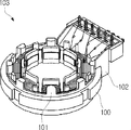
- Patent Document 1 discloses a ring-shaped stator 100 made of a magnetic material, a ring-shaped insulating cover 101 formed on both end surfaces of the ring-shaped stator 100, and a ring-shaped insulating cover 101 as shown in FIG.
- a resolver 103 is disclosed that includes an insulating connector unit 102 that is formed automatically.
- the ring-shaped insulating cover 100 is subjected to repeated heat-cooling tests due to the difference in thermal expansion coefficient between the ring-shaped stator 100 and the ring-shaped insulating cover 101 and the connector unit 102 which are resin parts. In some cases, a crack occurred between the connector 101 and the connector unit 102.
- An object of the present invention is to provide a technique for preventing the occurrence of cracks.
- a metal part and a first resin part as a resin part integrally formed with the metal part by injection molding a detection target is detected and a detection signal is detected.
- a detection device is provided in which the first resin component and the second resin component are separated.
- the first resin component and the second resin component each have a gate mark.
- the first resin component of the detection unit is formed in an annular shape, and the first resin component is divided in a circumferential direction of the first resin component.
- the first resin component is divided at a plurality of locations in the circumferential direction of the first resin component.
- a metal stator core having a plurality of teeth portions and an annular core body holding the plurality of teeth portions, and an integral with the annular core body by injection molding. Teeth resin parts as annular resin parts formed on, a plurality of terminals to which end portions of stator windings wound around the plurality of tooth parts can be connected, and the annular core body integrally by injection molding
- a resolver stator including a terminal holding resin part formed as a resin part for holding the plurality of terminals, wherein the tooth resin part and the terminal holding resin part are divided.
- Each of the tooth resin component and the terminal holding resin component has a gate mark.
- the teeth resin parts are divided in the circumferential direction of the teeth resin parts.
- the teeth resin parts are divided at a plurality of locations in the circumferential direction of the teeth resin parts.
- the tooth resin component is divided at a position that does not overlap any of the plurality of tooth portions in the circumferential direction of the tooth resin component.
- the resolver stator further includes the stator winding wound around the plurality of tooth portions.
- FIG. 1 is a perspective view of a stator.
- FIG. 2 is a perspective view of the stator as seen from another angle.
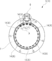
- FIG. 3 is a plan view of the stator.
- FIG. 4 is an enlarged view of part A in FIG.
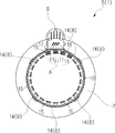
- FIG. 5 is a bottom view of the stator.
- FIG. 6 is an enlarged view of part A in FIG.
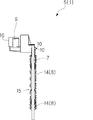
- FIG. 7 is a side view of the stator.
- FIG. 8 is a plan view of the stator core.
- FIG. 9 is a diagram corresponding to FIG.
- the resolver 1 (detection device) is for detecting the rotation angle position (detection target) of the output shaft 3 of the electric motor 2 and outputting a rotation angle signal (detection signal).
- the resolver 1 includes a stator 5 (resolver stator) fixed to the casing 4 of the electric motor 2 and a rotor 6 (resolver rotor) fixed to the output shaft 3 of the electric motor 2.
- the stator 5 includes a stator core 7 (metal part), a teeth resin part 8 (first resin part), a terminal holding resin part 9 (second resin part), and a plurality of terminals.
- a pin 10 (terminal) and a plurality of stator windings 11 are provided.
- the detection unit P that detects the rotation angle position of the output shaft 3 of the electric motor 2 and generates a rotation angle signal includes at least a stator core 7 and a tooth resin part 8.
- the detection unit P includes a stator core 7, a tooth resin part 8, and a plurality of stator windings 11.
- the output unit Q that outputs the rotation angle signal generated by the detection unit P includes at least the terminal holding resin component 9.
- the output part Q includes a terminal holding resin part 9 and a plurality of terminal pins 10.
- the stator core 7 is formed in an annular shape by laminating a plurality of electromagnetic steel plates.
- the stator core 7 includes a plurality of tooth portions 12 and an annular core body 13 that holds the plurality of tooth portions 12.
- the plurality of tooth portions 12 are disposed inside the core body 13.
- the plurality of tooth portions 12 are formed to protrude inward from the core body 13.
- the plurality of tooth portions 12 are arranged at equal intervals in the circumferential direction of the stator core 7.
- Teeth resin part 8 is an annular resin part formed integrally with annular stator core 7 by injection molding, as shown in FIGS.
- the teeth resin component 8 insulates the plurality of tooth portions 12 of the stator core 7.
- the teeth resin component 8 has six teeth resin divided bodies 14.
- the six teeth resin divided bodies 14 are arranged side by side in the circumferential direction of the stator core 7.
- Each tooth resin divided body 14 is formed in an arc shape.
- a cut 15 (second cut) is formed between two teeth resin divided bodies 14 adjacent in the circumferential direction of the stator core 7. That is, the teeth resin component 8 has six cuts 15.
- Each cut 15 (second cut) divides the tooth resin part 8 in the circumferential direction of the tooth resin part 8.
- the teeth resin component 8 is divided at six locations in the circumferential direction of the teeth resin component 8.
- the teeth resin component 8 is divided at the position of six cuts 15 (second cuts) in the circumferential direction of the teeth resin component 8.
- Each cut 15 (second cut) is a complete cut, and is formed as a result of completely prohibiting the passage of the molten resin during injection molding. Therefore, the two adjacent tooth resin divided bodies 14 are discontinuous.
- Each cut 15 (second cut) is formed so as not to overlap with the tooth portion 12 (see also FIG. 8) of the stator core 7 in the circumferential direction of the stator core 7. That is, the six teeth resin divided bodies 14 are arranged such that each cut 15 (second cut) does not overlap with the tooth portion 12 (see also FIG.
- each tooth resin divided body 14 has a gate mark 14 a.
- the terminal holding resin part 9 is a resin part integrally formed with the annular core body 13 by injection molding as shown in FIGS.
- the terminal holding resin component 9 holds six terminal pins 10 as shown in FIGS. 6 and 7.
- the terminal holding resin component 9 is formed to protrude from the stator core 7 along the central axis direction of the stator core 7.
- the terminal holding resin component 9 has a connector portion 16 that can be fitted with a mating connector.
- the terminal holding resin component 9 and the tooth resin component 8 are divided.
- the terminal holding resin component 9 and the tooth resin component 8 are formed apart from each other. Specifically, the terminal holding resin component 9 and the tooth resin divided body 14 of the tooth resin component 8 are divided.
- the terminal holding resin component 9 and the tooth resin divided body 14 of the tooth resin component 8 are formed apart from each other. That is, a cut 17 (first cut) is formed between the terminal holding resin component 9 and the tooth resin divided body 14 of the tooth resin component 8.
- the cut 17 (first cut) divides the terminal holding resin component 9 and the tooth resin divided body 14 of the tooth resin component 8 in the radial direction of the stator core 7.
- the cut 17 (first cut) is a complete cut, and is formed as a result of completely prohibiting the passage of the molten resin during injection molding. Therefore, the terminal holding resin component 9 and the tooth resin divided body 14 of the tooth resin component 8 are discontinuous.
- the terminal holding resin component 9 has a gate mark 9a.
- the plurality of stator windings 11 are wound around each tooth portion 12 of the stator core 7 as shown in FIGS. 4 and 6.
- Each stator winding 11 and each tooth portion 12 of the stator core 7 are electrically insulated by a tooth resin divided body 14 of the tooth resin component 8.
- the terminal pin 10 is connected to the end 11a of each stator winding 11 as shown in FIG.
- the resolver 1 (detection device) includes a detection unit P and an output unit Q.
- the detection unit P includes a stator core 7 (metal part) and a teeth resin part 8 (first resin part) as a resin part formed integrally with the stator core 7 by injection molding.
- the detection unit P detects a rotation angle position (detection target) of the output shaft 3 of the electric motor 2 and generates a rotation angle signal (detection signal).
- the output part Q includes a terminal holding resin part 9 (second resin part) as a resin part integrally formed with the stator core 7 by injection molding.
- the output unit Q outputs the rotation angle signal generated by the detection unit P.
- the teeth resin part 8 and the terminal holding resin part 9 are divided. According to the above configuration, it is possible to prevent cracks from occurring between the tooth resin component 8 and the terminal holding resin component 9.
- the teeth resin component 8 has a gate mark 14a.
- the terminal holding resin component 9 has a gate mark 9a. According to the above configuration, the tooth resin component 8 and the terminal holding resin component 9 can be formed such that the tooth resin component 8 and the terminal holding resin component 9 are separated from each other.
- the teeth resin part 8 of the detection part P is formed in an annular shape.
- the teeth resin component 8 is divided at a plurality of locations in the circumferential direction of the teeth resin component 8. According to the above configuration, since no weld is generated in the tooth resin component 8, it is possible to prevent a crack caused by the weld from occurring in the tooth resin component 8.
- the tooth resin component 8 of the detection unit P is divided at a plurality of locations in the circumferential direction of the tooth resin component 8.
- the tooth resin component 8 of the detection unit P may be divided at only one location. Even in this case, since no weld is generated in the tooth resin component 8, it is possible to prevent a crack caused by the weld from occurring in the tooth resin component 8.
- the stator 5 (resolver stator) includes a stator core 7, a tooth resin component 8, a plurality of terminal pins 10 (terminals), and a terminal holding resin component 9.
- the stator core 7 is made of metal having a plurality of tooth portions 12 and an annular core body 13 that holds the plurality of tooth portions 12.
- the teeth resin part 8 is an annular resin part formed integrally with the annular core body 13 by injection molding.
- the terminal holding resin component 9 is a resin component that is formed integrally with the annular core body 13 by injection molding and holds a plurality of terminal pins 10.
- the teeth resin part 8 and the terminal holding resin part 9 are divided. According to the above configuration, it is possible to prevent cracks from occurring between the tooth resin component 8 and the terminal holding resin component 9.
- the teeth resin component 8 has a gate mark 14a.
- the terminal holding resin component 9 has a gate mark 9a. According to the above configuration, the tooth resin component 8 and the terminal holding resin component 9 can be formed such that the tooth resin component 8 and the terminal holding resin component 9 are separated from each other.
- the teeth resin component 8 is divided in a circumferential direction of the teeth resin component 8 at a position that does not overlap any of the plurality of tooth portions 12. According to the above configuration, it can be avoided that the division of the tooth resin component 8 adversely affects the insulation performance between the tooth portion 12 and the stator winding 11.
- the stator 5 further includes a stator winding 11 wound around the plurality of tooth portions 12.
- the resolver 1 of this embodiment is for detecting the rotational angle position of the output shaft 3 of the electric motor 2 and outputting a rotational angle signal.
- the resolver 1 may be used for detecting the rotational angle position of the output shaft of a prime mover such as an engine and outputting the rotational angle signal.
- the resolver 1 can be used to detect the rotation angle position of a rotating object and output a rotation angle signal.
Landscapes
- Physics & Mathematics (AREA)
- General Physics & Mathematics (AREA)
- Transmission And Conversion Of Sensor Element Output (AREA)
- Injection Moulding Of Plastics Or The Like (AREA)
Abstract
レゾルバ(1)は、検出部(P)と出力部(Q)を備える。検出部(P)は、ステータコア(7)と、射出成形によりステータコア(7)と一体的に形成される樹脂部品としてのティース樹脂部品(8)と、を含む。検出部(P)は、電動機(2)の出力軸(3)の回転角度位置を検出して回転角度信号を生成する。出力部(Q)は、射出成形によりステータコア(7)と一体的に形成される樹脂部品としての端子保持樹脂部品(9)を含む。出力部(Q)は、検出部(P)が生成した回転角度信号を出力する。ティース樹脂部品(8)と端子保持樹脂部品(9)は、分断されている。
Description
本発明は、検出装置及びレゾルバステータに関する。
この種の技術として、特許文献1は、本願の図9に示すように、磁性材料の輪状ステータ100と、輪状ステータ100の両端面に形成された輪状絶縁カバー101と、輪状絶縁カバー101と一体的に形成された絶縁性のコネクタユニット102と、を備えたレゾルバ103を開示している。
しかし、上記特許文献1の構成では、輪状ステータ100と、樹脂部品である輪状絶縁カバー101及びコネクタユニット102と、の熱膨張率の相違に起因して、熱冷繰り返し試験の際、輪状絶縁カバー101とコネクタユニット102の間にクラックが発生する場合があった。
本願発明の目的は、クラックの発生を防止する技術を提供することにある。
本願発明の第1の観点によれば、金属部品と、射出成形により前記金属部品と一体的に形成される樹脂部品としての第1樹脂部品と、を含み、検出対象を検出して検出信号を生成する検出部と、射出成形により前記金属部品と一体的に形成される樹脂部品としての第2樹脂部品を含み、前記検出部が生成した前記検出信号を出力する出力部と、を備え、前記第1樹脂部品と前記第2樹脂部品は、分断されている、検出装置が提供される。
前記第1樹脂部品と前記第2樹脂部品は、夫々、ゲート痕を有する。
前記検出部の前記第1樹脂部品は、環状に形成されており、前記第1樹脂部品は、前記第1樹脂部品の周方向において、分断されている。
前記第1樹脂部品は、前記第1樹脂部品の周方向において、複数箇所で、分断されている。
本願発明の第2の観点によれば、複数のティース部と、前記複数のティース部を保持する環状のコア本体と、を有する金属製のステータコアと、射出成形により前記環状のコア本体と一体的に形成される環状の樹脂部品としてのティース樹脂部品と、前記複数のティース部に巻かれるステータ巻線の端部が接続可能な複数の端子と、射出成形により前記環状のコア本体と一体的に形成され、前記複数の端子を保持する樹脂部品としての端子保持樹脂部品と、を備え、前記ティース樹脂部品と前記端子保持樹脂部品は、分断されている、レゾルバステータが提供される。
前記ティース樹脂部品と前記端子保持樹脂部品は、夫々、ゲート痕を有する。
前記ティース樹脂部品は、前記ティース樹脂部品の周方向において、分断されている。
前記ティース樹脂部品は、前記ティース樹脂部品の周方向において、複数箇所で、分断されている。
前記ティース樹脂部品は、前記ティース樹脂部品の周方向において、前記複数のティース部の何れにも重複しない位置で、分断されている。
前記レゾルバステータは、前記複数のティース部に巻かれた前記ステータ巻線を更に備えた。
前記第1樹脂部品と前記第2樹脂部品は、夫々、ゲート痕を有する。
前記検出部の前記第1樹脂部品は、環状に形成されており、前記第1樹脂部品は、前記第1樹脂部品の周方向において、分断されている。
前記第1樹脂部品は、前記第1樹脂部品の周方向において、複数箇所で、分断されている。
本願発明の第2の観点によれば、複数のティース部と、前記複数のティース部を保持する環状のコア本体と、を有する金属製のステータコアと、射出成形により前記環状のコア本体と一体的に形成される環状の樹脂部品としてのティース樹脂部品と、前記複数のティース部に巻かれるステータ巻線の端部が接続可能な複数の端子と、射出成形により前記環状のコア本体と一体的に形成され、前記複数の端子を保持する樹脂部品としての端子保持樹脂部品と、を備え、前記ティース樹脂部品と前記端子保持樹脂部品は、分断されている、レゾルバステータが提供される。
前記ティース樹脂部品と前記端子保持樹脂部品は、夫々、ゲート痕を有する。
前記ティース樹脂部品は、前記ティース樹脂部品の周方向において、分断されている。
前記ティース樹脂部品は、前記ティース樹脂部品の周方向において、複数箇所で、分断されている。
前記ティース樹脂部品は、前記ティース樹脂部品の周方向において、前記複数のティース部の何れにも重複しない位置で、分断されている。
前記レゾルバステータは、前記複数のティース部に巻かれた前記ステータ巻線を更に備えた。
本願発明によれば、前記第1樹脂部品と前記第2樹脂部品の間でクラックが発生するのを防止できる。
図1に示すように、レゾルバ1(検出装置)は、電動機2の出力軸3の回転角度位置(検出対象)を検出して回転角度信号(検出信号)を出力するためのものである。レゾルバ1は、電動機2のケーシング4に固定されるステータ5(レゾルバステータ)と、電動機2の出力軸3に固定されるロータ6(レゾルバロータ)と、を有する。
図1~図8に示すように、ステータ5は、ステータコア7(金属部品)と、ティース樹脂部品8(第1樹脂部品)と、端子保持樹脂部品9(第2樹脂部品)と、複数の端子ピン10(端子)と、複数のステータ巻線11と、を有する。
図1に示すように、電動機2の出力軸3の回転角度位置を検出して回転角度信号を生成する検出部Pは、少なくとも、ステータコア7とティース樹脂部品8を含む。検出部Pは、ステータコア7とティース樹脂部品8、複数のステータ巻線11を含む。検出部Pが生成した回転角度信号を出力する出力部Qは、少なくとも、端子保持樹脂部品9を含む。出力部Qは、端子保持樹脂部品9と複数の端子ピン10を含む。
ステータコア7は、図8に示すように、複数の電磁鋼板を積層して環状に構成されている。ステータコア7は、複数のティース部12と、複数のティース部12を保持する環状のコア本体13と、を有する。複数のティース部12は、コア本体13の内側に配置されている。複数のティース部12は、コア本体13から内側に突出して形成されている。複数のティース部12は、ステータコア7の周方向において等間隔に配置されている。
ティース樹脂部品8は、図3~図7に示すように、射出成形により環状のステータコア7と一体的に形成される環状の樹脂部品である。ティース樹脂部品8は、ステータコア7の複数のティース部12を絶縁被覆している。ティース樹脂部品8は、6つのティース樹脂分割体14を有する。6つのティース樹脂分割体14は、ステータコア7の周方向に並べて配置されている。各ティース樹脂分割体14は、円弧状に形成されている。ステータコア7の周方向において隣り合う2つのティース樹脂分割体14の間には、切れ目15(第2の切れ目)が形成されている。即ち、ティース樹脂部品8は、6つの切れ目15を有する。各切れ目15(第2の切れ目)は、ティース樹脂部品8をティース樹脂部品8の周方向において分断している。即ち、ティース樹脂部品8は、ティース樹脂部品8の周方向において、6箇所で、分断されている。ティース樹脂部品8は、ティース樹脂部品8の周方向において、6つの切れ目15(第2の切れ目)の位置で、分断されている。各切れ目15(第2の切れ目)は、完全な切れ目であって、射出成形の際に溶融樹脂の通過を完全に禁止した結果として形成される。従って、隣り合う2つのティース樹脂分割体14は不連続である。各切れ目15(第2の切れ目)は、ステータコア7の周方向においてステータコア7のティース部12(図8を併せて参照)と重複しないように形成されている。即ち、6つのティース樹脂分割体14は、各切れ目15(第2の切れ目)がステータコア7の周方向においてステータコア7のティース部12(図8を併せて参照)と重複しないように配置されている。ティース樹脂部品8は、ティース樹脂部品8の周方向において、ステータコア7のティース部12(図8を併せて参照)と重複しない位置で、分断されている。図4に示すように、各ティース樹脂分割体14は、夫々、ゲート痕14aを有している。
端子保持樹脂部品9は、図3~図7に示すように、射出成形により環状のコア本体13と一体的に形成される樹脂部品である。端子保持樹脂部品9は、図6及び図7に示すように、6つの端子ピン10を保持する。図7に示すように、端子保持樹脂部品9は、ステータコア7からステータコア7の中心軸方向に沿って突出して形成されている。端子保持樹脂部品9は、相手コネクタと嵌合可能なコネクタ部16を有する。図4及び図6に示すように、端子保持樹脂部品9とティース樹脂部品8は、分断されている。端子保持樹脂部品9とティース樹脂部品8は、互いに離れて形成されている。詳しく言えば、端子保持樹脂部品9とティース樹脂部品8のティース樹脂分割体14は、分断されている。端子保持樹脂部品9とティース樹脂部品8のティース樹脂分割体14は、互いに離れて形成されている。つまり、端子保持樹脂部品9と、ティース樹脂部品8のティース樹脂分割体14と、の間には、切れ目17(第1の切れ目)が形成されている。切れ目17(第1の切れ目)は、端子保持樹脂部品9と、ティース樹脂部品8のティース樹脂分割体14と、をステータコア7の径方向において分断している。切れ目17(第1の切れ目)は、完全な切れ目であって、射出成形の際に溶融樹脂の通過を完全に禁止した結果として形成される。従って、端子保持樹脂部品9と、ティース樹脂部品8のティース樹脂分割体14と、は不連続である。図4に示すように、端子保持樹脂部品9は、ゲート痕9aを有している。
複数のステータ巻線11は、図4及び図6に示すように、ステータコア7の各ティース部12に巻かれている。各ステータ巻線11と、ステータコア7の各ティース部12と、はティース樹脂部品8のティース樹脂分割体14によって電気的に絶縁されている。
端子ピン10は、図6に示すように、各ステータ巻線11の端部11aが接続されている。
以上の構成で、図1に示す出力軸3が回転すると、出力軸3の回転角度位置に応じた回転角度信号が検出部Pで生成される。回転角度信号は、出力部Qを介して相手コネクタに出力される。
以上に、本願発明の好適な実施形態を説明したが、上記実施形態は、以下の特長を有する。
(1)レゾルバ1(検出装置)は、検出部Pと出力部Qを備える。検出部Pは、ステータコア7(金属部品)と、射出成形によりステータコア7と一体的に形成される樹脂部品としてのティース樹脂部品8(第1樹脂部品)と、を含む。検出部Pは、電動機2の出力軸3の回転角度位置(検出対象)を検出して回転角度信号(検出信号)を生成する。出力部Qは、射出成形によりステータコア7と一体的に形成される樹脂部品としての端子保持樹脂部品9(第2樹脂部品)を含む。出力部Qは、検出部Pが生成した回転角度信号を出力する。ティース樹脂部品8と端子保持樹脂部品9は、分断されている。以上の構成によれば、ティース樹脂部品8と端子保持樹脂部品9の間でクラックが発生するのを防止できる。
なお、射出成形の分野における当業者であれば、ティース樹脂部品8と端子保持樹脂部品9を射出成形の際、分割して形成することはありえない。なぜなら、ティース樹脂部品8と端子保持樹脂部品9を分割して形成しようとすると、その分、金型の構造が複雑になりコストアップを招くからである。従って、上記実施形態のようにティース樹脂部品8と端子保持樹脂部品9を分割して形成することは、それ自体が創作非容易と言える。
(2)ティース樹脂部品8は、ゲート痕14aを有する。端子保持樹脂部品9は、ゲート痕9aを有する。以上の構成によれば、ティース樹脂部品8と端子保持樹脂部品9を、ティース樹脂部品8と端子保持樹脂部品9が互いに離れるように、形成することができる。
(3、4、7、8)検出部Pのティース樹脂部品8は、環状に形成されている。ティース樹脂部品8は、ティース樹脂部品8の周方向において、複数箇所で、分断されている。以上の構成によれば、ティース樹脂部品8にウェルドが発生しないので、ティース樹脂部品8にウェルド起因のクラックが発生するのを防止できる。
なお、上記実施形態では、検出部Pのティース樹脂部品8は、ティース樹脂部品8の周方向において、複数箇所で、分断されている。しかし、検出部Pのティース樹脂部品8は、1箇所のみで、分断されていてもよい。この場合でも、ティース樹脂部品8にウェルドが発生しないので、ティース樹脂部品8にウェルド起因のクラックが発生するのを防止できる。
なお、射出成形の分野における当業者であれば、検出部Pのティース樹脂部品8を射出成形の際、分割して形成することはありえない。なぜなら、検出部Pのティース樹脂部品8を分割して形成しようとすると、その分、金型の構造が複雑になりコストアップを招くからである。従って、上記実施形態のように検出部Pのティース樹脂部品8を分割して形成することは、それ自体が創作非容易と言える。
(5)ステータ5(レゾルバステータ)は、ステータコア7と、ティース樹脂部品8と、複数の端子ピン10(端子)と、端子保持樹脂部品9と、を備える。ステータコア7は、複数のティース部12と、複数のティース部12を保持する環状のコア本体13と、を有する金属製である。ティース樹脂部品8は、射出成形により環状のコア本体13と一体的に形成される環状の樹脂部品である。複数の端子ピン10には、複数のティース部12に巻かれるステータ巻線11の端部11aが接続可能である。端子保持樹脂部品9は、射出成形により環状のコア本体13と一体的に形成され、複数の端子ピン10を保持する樹脂部品である。ティース樹脂部品8と端子保持樹脂部品9は、分断されている。以上の構成によれば、ティース樹脂部品8と端子保持樹脂部品9の間でクラックが発生するのを防止できる。
(6)ティース樹脂部品8は、ゲート痕14aを有する。端子保持樹脂部品9は、ゲート痕9aを有する。以上の構成によれば、ティース樹脂部品8と端子保持樹脂部品9を、ティース樹脂部品8と端子保持樹脂部品9が互いに離れるように、形成することができる。
(9)ティース樹脂部品8は、ティース樹脂部品8の周方向において、複数のティース部12の何れにも重複しない位置で、分断されている。以上の構成によれば、ティース樹脂部品8を分断したことが、ティース部12とステータ巻線11との絶縁性能に悪影響を与えるのを回避できる。
(10)ステータ5は、複数のティース部12に巻かれたステータ巻線11を更に備える。
なお、本実施形態のレゾルバ1は、電動機2の出力軸3の回転角度位置を検出して回転角度信号を出力するためのものであるとした。しかし、これに代えて、レゾルバ1は、例えばエンジンなどの原動機の出力軸の回転角度位置を検出して回転角度信号を出力するのに用いてもよい。更に言えば、レゾルバ1は、回転する物体の回転角度位置を検出して回転角度信号を出力するのに用いることができる。
この出願は、2013年6月26日に出願された日本出願特願2013-133654を基礎とする優先権を主張し、その開示の全てをここに取り込む。
1 レゾルバ(検出装置)
2 電動機
3 出力軸
4 ケーシング
5 ステータ(レゾルバステータ)
6 ロータ
7 ステータコア(金属部品)
8 ティース樹脂部品(第1樹脂部品)
9 端子保持樹脂部品(第2樹脂部品)
9a ゲート痕
10 端子ピン(端子)
11 ステータ巻線
11a 端部
12 ティース部
13 コア本体
14 ティース樹脂分割体
14a ゲート痕
15 切れ目(第2の切れ目)
16 コネクタ部
17 切れ目(第1の切れ目)
P 検出部
Q 出力部
2 電動機
3 出力軸
4 ケーシング
5 ステータ(レゾルバステータ)
6 ロータ
7 ステータコア(金属部品)
8 ティース樹脂部品(第1樹脂部品)
9 端子保持樹脂部品(第2樹脂部品)
9a ゲート痕
10 端子ピン(端子)
11 ステータ巻線
11a 端部
12 ティース部
13 コア本体
14 ティース樹脂分割体
14a ゲート痕
15 切れ目(第2の切れ目)
16 コネクタ部
17 切れ目(第1の切れ目)
P 検出部
Q 出力部
Claims (10)
- 金属部品と、射出成形により前記金属部品と一体的に形成される樹脂部品としての第1樹脂部品と、を含み、検出対象を検出して検出信号を生成する検出部と、
射出成形により前記金属部品と一体的に形成される樹脂部品としての第2樹脂部品を含み、前記検出部が生成した前記検出信号を出力する出力部と、
を備え、
前記第1樹脂部品と前記第2樹脂部品は、分断されている、
検出装置。 - 請求項1に記載の検出装置であって、
前記第1樹脂部品と前記第2樹脂部品は、夫々、ゲート痕を有する、
検出装置。 - 請求項1又は2に記載の検出装置であって、
前記検出部の前記第1樹脂部品は、環状に形成されており、
前記第1樹脂部品は、前記第1樹脂部品の周方向において、分断されている、
検出装置。 - 請求項3に記載の検出装置であって、
前記第1樹脂部品は、前記第1樹脂部品の周方向において、複数箇所で、分断されている、
検出装置。 - 複数のティース部と、前記複数のティース部を保持する環状のコア本体と、を有する金属製のステータコアと、
射出成形により前記環状のコア本体と一体的に形成される環状の樹脂部品としてのティース樹脂部品と、
前記複数のティース部に巻かれるステータ巻線の端部が接続可能な複数の端子と、
射出成形により前記環状のコア本体と一体的に形成され、前記複数の端子を保持する樹脂部品としての端子保持樹脂部品と、
を備え、
前記ティース樹脂部品と前記端子保持樹脂部品は、分断されている、
レゾルバステータ。 - 請求項5に記載のレゾルバステータであって、
前記ティース樹脂部品と前記端子保持樹脂部品は、夫々、ゲート痕を有する、
レゾルバステータ。 - 請求項5又は6に記載のレゾルバステータであって、
前記ティース樹脂部品は、前記ティース樹脂部品の周方向において、分断されている、
レゾルバステータ。 - 請求項7に記載のレゾルバステータであって、
前記ティース樹脂部品は、前記ティース樹脂部品の周方向において、複数箇所で、分断されている、
レゾルバステータ。 - 請求項7又は8に記載のレゾルバステータであって、
前記ティース樹脂部品は、前記ティース樹脂部品の周方向において、前記複数のティース部の何れにも重複しない位置で、分断されている、
レゾルバステータ。 - 請求項5~9の何れかに記載のレゾルバステータであって、
前記複数のティース部に巻かれた前記ステータ巻線を更に備えた、
レゾルバステータ。
Applications Claiming Priority (2)
| Application Number | Priority Date | Filing Date | Title |
|---|---|---|---|
| JP2013133654A JP6309212B2 (ja) | 2013-06-26 | 2013-06-26 | 検出装置及びレゾルバステータ |
| JP2013-133654 | 2013-06-26 |
Publications (1)
| Publication Number | Publication Date |
|---|---|
| WO2014208014A1 true WO2014208014A1 (ja) | 2014-12-31 |
Family
ID=52141389
Family Applications (1)
| Application Number | Title | Priority Date | Filing Date |
|---|---|---|---|
| PCT/JP2014/002982 Ceased WO2014208014A1 (ja) | 2013-06-26 | 2014-06-04 | 検出装置及びレゾルバステータ |
Country Status (2)
| Country | Link |
|---|---|
| JP (1) | JP6309212B2 (ja) |
| WO (1) | WO2014208014A1 (ja) |
Cited By (2)
| Publication number | Priority date | Publication date | Assignee | Title |
|---|---|---|---|---|
| CN109639084A (zh) * | 2017-10-09 | 2019-04-16 | 泰科电子比利时公司 | 用于可变磁阻型角度传感器的定子芯 |
| CZ310051B6 (cs) * | 2020-02-25 | 2024-06-19 | Vysoké Učení Technické V Brně | Resolver s nesymetrickým vinutím |
Families Citing this family (2)
| Publication number | Priority date | Publication date | Assignee | Title |
|---|---|---|---|---|
| JP7471644B2 (ja) * | 2020-09-29 | 2024-04-22 | 多摩川精機株式会社 | レゾルバステータ構造 |
| DE102021126356A1 (de) | 2021-10-12 | 2023-04-13 | Schaeffler Technologies AG & Co. KG | Sensoreinrichtung zur Erfassung einer Drehposition eines Rotors mit integrierter Temperatursignalleitung |
Citations (6)
| Publication number | Priority date | Publication date | Assignee | Title |
|---|---|---|---|---|
| JP2000283705A (ja) * | 1999-03-30 | 2000-10-13 | Bosch Braking Systems Co Ltd | 回転検出装置 |
| JP2001352733A (ja) * | 2000-06-06 | 2001-12-21 | Tamagawa Seiki Co Ltd | レゾルバ用ステータの絶縁構造 |
| JP2003214904A (ja) * | 2002-01-23 | 2003-07-30 | Mitsubishi Electric Corp | 回転角度検出器 |
| JP2011239529A (ja) * | 2010-05-07 | 2011-11-24 | Tamagawa Seiki Co Ltd | 回転角検出又は回転同期装置用のステータ構造及びその製造方法 |
| JP2013051825A (ja) * | 2011-08-31 | 2013-03-14 | Minebea Co Ltd | Vr型レゾルバ |
| JP2013091427A (ja) * | 2011-10-26 | 2013-05-16 | Toyota Auto Body Co Ltd | 乗用車のバンパー |
Family Cites Families (4)
| Publication number | Priority date | Publication date | Assignee | Title |
|---|---|---|---|---|
| JP2003344107A (ja) * | 2002-05-31 | 2003-12-03 | Tamagawa Seiki Co Ltd | 回転検出器用ステータ構造 |
| JP2008187787A (ja) * | 2007-01-29 | 2008-08-14 | Nippon Densan Corp | レゾルバおよびモータ |
| CN101578020B (zh) * | 2008-05-09 | 2012-03-14 | 富准精密工业(深圳)有限公司 | 壳体及其制造方法 |
| JP5827840B2 (ja) * | 2011-08-30 | 2015-12-02 | ミネベア株式会社 | Vr型レゾルバ |
-
2013
- 2013-06-26 JP JP2013133654A patent/JP6309212B2/ja not_active Expired - Fee Related
-
2014
- 2014-06-04 WO PCT/JP2014/002982 patent/WO2014208014A1/ja not_active Ceased
Patent Citations (6)
| Publication number | Priority date | Publication date | Assignee | Title |
|---|---|---|---|---|
| JP2000283705A (ja) * | 1999-03-30 | 2000-10-13 | Bosch Braking Systems Co Ltd | 回転検出装置 |
| JP2001352733A (ja) * | 2000-06-06 | 2001-12-21 | Tamagawa Seiki Co Ltd | レゾルバ用ステータの絶縁構造 |
| JP2003214904A (ja) * | 2002-01-23 | 2003-07-30 | Mitsubishi Electric Corp | 回転角度検出器 |
| JP2011239529A (ja) * | 2010-05-07 | 2011-11-24 | Tamagawa Seiki Co Ltd | 回転角検出又は回転同期装置用のステータ構造及びその製造方法 |
| JP2013051825A (ja) * | 2011-08-31 | 2013-03-14 | Minebea Co Ltd | Vr型レゾルバ |
| JP2013091427A (ja) * | 2011-10-26 | 2013-05-16 | Toyota Auto Body Co Ltd | 乗用車のバンパー |
Cited By (2)
| Publication number | Priority date | Publication date | Assignee | Title |
|---|---|---|---|---|
| CN109639084A (zh) * | 2017-10-09 | 2019-04-16 | 泰科电子比利时公司 | 用于可变磁阻型角度传感器的定子芯 |
| CZ310051B6 (cs) * | 2020-02-25 | 2024-06-19 | Vysoké Učení Technické V Brně | Resolver s nesymetrickým vinutím |
Also Published As
| Publication number | Publication date |
|---|---|
| JP2015010822A (ja) | 2015-01-19 |
| JP6309212B2 (ja) | 2018-04-11 |
Similar Documents
| Publication | Publication Date | Title |
|---|---|---|
| JP6070665B2 (ja) | 回転電機ステータ | |
| CN108880013B (zh) | 定子构造以及旋转变压器 | |
| US9136748B2 (en) | Variable reluctance resolver | |
| JP7190533B2 (ja) | ステータ | |
| JP6969894B2 (ja) | ステータおよびレゾルバ | |
| JP6366986B2 (ja) | 同期リラクタンス型回転電機 | |
| JP5970355B2 (ja) | ステータ | |
| JP5862615B2 (ja) | レゾルバステータおよびその固定構造 | |
| JP6309212B2 (ja) | 検出装置及びレゾルバステータ | |
| WO2013008568A1 (ja) | 回転電機及び回転電機の固定子コイルの製造方法 | |
| WO2016042745A1 (ja) | レゾルバステータ | |
| CN106710831A (zh) | 定子结构及旋转变压器 | |
| WO2013084270A1 (ja) | 電動機 | |
| JP5785586B2 (ja) | 電動車両 | |
| KR102489299B1 (ko) | 모터 | |
| JP2017189095A (ja) | ステータ構造およびレゾルバ | |
| JP6339052B2 (ja) | レゾルバ | |
| JP7046634B2 (ja) | ステータ構造およびレゾルバ | |
| JP2008312369A (ja) | モータおよびモータの製造方法 | |
| JP6154310B2 (ja) | レゾルバ | |
| KR102621316B1 (ko) | 로터 플레이트. 로터코어 조립체, 모터 및 이를 포함하는 차량 | |
| KR20170085308A (ko) | 로터 플레이트. 로터코어 조립체, 모터 및 이를 포함하는 차량 | |
| JP6349562B2 (ja) | レゾルバ | |
| WO2019142776A1 (ja) | ステータ構造およびレゾルバ | |
| JP2016127614A (ja) | レゾルバステータ構造及びその磁気遮蔽方法 |
Legal Events
| Date | Code | Title | Description |
|---|---|---|---|
| 121 | Ep: the epo has been informed by wipo that ep was designated in this application |
Ref document number: 14816929 Country of ref document: EP Kind code of ref document: A1 |
|
| NENP | Non-entry into the national phase |
Ref country code: DE |
|
| 122 | Ep: pct application non-entry in european phase |
Ref document number: 14816929 Country of ref document: EP Kind code of ref document: A1 |