WO2014203415A1 - 靴紐巻取装置 - Google Patents
靴紐巻取装置 Download PDFInfo
- Publication number
- WO2014203415A1 WO2014203415A1 PCT/JP2013/078116 JP2013078116W WO2014203415A1 WO 2014203415 A1 WO2014203415 A1 WO 2014203415A1 JP 2013078116 W JP2013078116 W JP 2013078116W WO 2014203415 A1 WO2014203415 A1 WO 2014203415A1
- Authority
- WO
- WIPO (PCT)
- Prior art keywords
- dial
- reel
- spring
- winding device
- shoelace
- Prior art date
Links
- 238000004804 winding Methods 0.000 title claims abstract description 67
- 238000003860 storage Methods 0.000 claims description 11
- 238000003780 insertion Methods 0.000 claims description 5
- 230000037431 insertion Effects 0.000 claims description 5
- 238000012423 maintenance Methods 0.000 abstract description 5
- 230000006835 compression Effects 0.000 abstract description 2
- 238000007906 compression Methods 0.000 abstract description 2
- 210000000078 claw Anatomy 0.000 description 6
- 239000011347 resin Substances 0.000 description 5
- 229920005989 resin Polymers 0.000 description 5
- 239000000463 material Substances 0.000 description 4
- 239000002184 metal Substances 0.000 description 4
- 230000002093 peripheral effect Effects 0.000 description 4
- 239000004677 Nylon Substances 0.000 description 3
- 238000000034 method Methods 0.000 description 3
- 229920001778 nylon Polymers 0.000 description 3
- 230000000386 athletic effect Effects 0.000 description 2
- 229920006324 polyoxymethylene Polymers 0.000 description 2
- 239000010935 stainless steel Substances 0.000 description 2
- 229910001220 stainless steel Inorganic materials 0.000 description 2
- 229920002725 thermoplastic elastomer Polymers 0.000 description 2
- 229910000975 Carbon steel Inorganic materials 0.000 description 1
- 229930182556 Polyacetal Natural products 0.000 description 1
- 229910000831 Steel Inorganic materials 0.000 description 1
- 230000004308 accommodation Effects 0.000 description 1
- 229920000122 acrylonitrile butadiene styrene Polymers 0.000 description 1
- 210000003423 ankle Anatomy 0.000 description 1
- 239000010962 carbon steel Substances 0.000 description 1
- 230000009194 climbing Effects 0.000 description 1
- 239000002131 composite material Substances 0.000 description 1
- 230000001276 controlling effect Effects 0.000 description 1
- 238000005520 cutting process Methods 0.000 description 1
- 239000000428 dust Substances 0.000 description 1
- 238000009434 installation Methods 0.000 description 1
- 238000004519 manufacturing process Methods 0.000 description 1
- 238000003825 pressing Methods 0.000 description 1
- 230000001105 regulatory effect Effects 0.000 description 1
- 238000009958 sewing Methods 0.000 description 1
- 239000010959 steel Substances 0.000 description 1
Images

Classifications
-
- A—HUMAN NECESSITIES
- A43—FOOTWEAR
- A43C—FASTENINGS OR ATTACHMENTS OF FOOTWEAR; LACES IN GENERAL
- A43C11/00—Other fastenings specially adapted for shoes
- A43C11/16—Fastenings secured by wire, bolts, or the like
- A43C11/165—Fastenings secured by wire, bolts, or the like characterised by a spool, reel or pulley for winding up cables, laces or straps by rotation
-
- A—HUMAN NECESSITIES
- A43—FOOTWEAR
- A43C—FASTENINGS OR ATTACHMENTS OF FOOTWEAR; LACES IN GENERAL
- A43C11/00—Other fastenings specially adapted for shoes
- A43C11/16—Fastenings secured by wire, bolts, or the like
-
- A—HUMAN NECESSITIES
- A43—FOOTWEAR
- A43B—CHARACTERISTIC FEATURES OF FOOTWEAR; PARTS OF FOOTWEAR
- A43B11/00—Footwear with arrangements to facilitate putting-on or removing, e.g. with straps
-
- A—HUMAN NECESSITIES
- A43—FOOTWEAR
- A43B—CHARACTERISTIC FEATURES OF FOOTWEAR; PARTS OF FOOTWEAR
- A43B23/00—Uppers; Boot legs; Stiffeners; Other single parts of footwear
- A43B23/02—Uppers; Boot legs
-
- A—HUMAN NECESSITIES
- A43—FOOTWEAR
- A43C—FASTENINGS OR ATTACHMENTS OF FOOTWEAR; LACES IN GENERAL
- A43C7/00—Holding-devices for laces
Definitions
- the present invention relates to a shoelace winding device, and is not limited to boots for skiing, snowboarding, skating, mountain climbing, motorcycle riding, athletic shoes used for golf, jogging, etc.
- the present invention relates to a shoelace winding device suitable for tightening a shoelace of a simple shoe.
- the shoelace is tightened by the dial by sliding the resin protrusion (sawtooth washer) and engaging it with either a “connection recess” or “non-connection recess”.
- An operation for switching between a locked state in which the shoelace can be released and a release state in which the shoelace can be released from being tightened is enabled.
- connection recess Even in the embodiment in which a spring made of a steel wire is used in place of the protrusion and the spring is moved between the “connection recess” and the “non-connection recess”, the “connection recess” and the “non-connection” are also used. There is a problem that the “mountains” between the “dents” are worn and lack durability and reliability.
- the problem to be solved by the present invention is to switch between a locked state in which the shoelace can be tightened and a release state in which the shoelace can be unfastened in the conventional shoelace winding device. Repeating is likely to cause failure due to wear, and in order to improve strength and durability, it is necessary to use a lot of metal parts or make resin parts large.
- the object of the present invention is small and lightweight , Durability and reliability can be improved, as well as easy to disassemble during assembly and repair, excellent operability, and shoelace winding that can be used for a wider variety of shoes To provide an apparatus.
- the present invention provides a "reel for winding a shoelace, a base member having a reel storage unit for storing the reel, and a dial for rotationally driving the reel, the rotation of the dial being A dial having a stopper member for realizing a locked state that can be transmitted to the reel and a released state in which the reel is separated from the dial so that the reel can freely rotate, and the dial for attaching the dial to the base member A shaft member fixed to the base member, the shaft capable of being held and guided in a movable state between a lock position where the dial is brought close to the base member and a release position separated from the base member.
- a spring member having one end pivotally supported by a member and a bearing formed on a side of the shaft member in a direction orthogonal to the axial direction of the shaft member, the other end And a spring member in contact at all times and the locking portion provided on the inner surface of the dial,
- a shoelace winding device that can be switched from a locked state of a reel to a released state by moving the dial from a locked position to a released position, wherein the spring member is at a position between the locked position and the released position.
- a shoelace winding device wherein a reversal position to be compressed is set, and a direction in which the spring member is compressed is switched between the lock position and the release position.
- the stopper member fits inside the dial and is integrated with the dial, and the locking portion with which the other end of the spring member abuts is wedge-shaped at the boundary between the dial and the stopper member. You may provide in the outer end narrowest part of the formed spring accommodation space.
- the other end portion of the spring member extends from the extended portion where the shaft hole of the dial is expanded into the spring accommodating space.
- the other end portion may be inserted and guided so as to rotate from the inner end side of the spring accommodating space to the outer end narrowest portion side and assembled to the dial.
- the spring member is a spring member that is curved in a substantially U shape, and a linear shaft portion on one end side thereof is formed on a side portion of the shaft member in a direction perpendicular to the axial direction of the shaft member.
- the spring portion on the other end side that is pivotally supported by the formed bearing portion and that is curved may abut against the locking portion.
- one spring member may be disposed at a position about 180 degrees apart from the shaft member.
- the other end of the spring member whose one end is pivotally supported is always in contact with a locking portion provided on the inner surface of the dial when the dial is switched between the locked state and the released state. Therefore, when the dial moves from the lock position to the release position, the position where the spring member and the parts such as the dial are in contact does not change, so that the spring member and the parts such as the dial are prevented from rubbing and wearing. Can do.
- the reverse position where the spring member is most compressed is set at a position between the lock position and the release position of the dial, the spring member is compressed to move the dial from the lock position to the release position. Therefore, it is possible to prevent the dial from being inadvertently moved from the lock position to the release position. Furthermore, since the direction in which the spring member is compressed is switched between the lock position and the release position of the dial, the operability is excellent and the state of the dial can be clearly grasped.
- the stopper member By fitting the stopper member inside the dial so as to be integrated with the dial, it is possible to easily provide a component having a complicated shape. Furthermore, by providing the locking portion with which the other end portion of the spring member abuts at the narrowest outer end portion of the spring accommodating space formed in a wedge shape at the boundary portion between the dial and the stopper member, the spring member is accommodated. The reliability and durability of the device can be improved, and the operating range of the spring member can be correctly regulated.
- the other end portion of the spring member extends from the extended portion where the shaft hole of the dial is expanded into the spring accommodating space.
- the spring member is inserted into the dial and guided to be pivoted from the inner end side to the outer end narrowest portion side of the spring accommodating space and assembled to the dial.
- the spring member can be easily assembled by simply pushing it in.
- the spring member is a spring member that is formed in a substantially U-shape, and a linear shaft portion on one end side thereof is formed on a side portion of the shaft member in a direction orthogonal to the axial direction of the shaft member.
- the spring portion that is pivotally supported by the formed bearing portion and curved on the other end side comes into contact with the locking portion, so that the spring portion can rotate around the shaft portion.
- the spring portion is curved, the spring portion and the locking portion come into smooth contact when the spring member is compressively deformed, and the spring member can be smoothly deformed. That is, the compression operation of the spring member can be performed smoothly, and the operability can be improved when changing the dial position.
- FIG. 1 is a perspective view of a shoe equipped with a shoelace winding device embodying the present invention, and a cross-sectional view of the shoelace winding device, wherein (a) shows a state where a dial is in a locked position. (B) is a figure which shows the state which has a dial in a cancellation
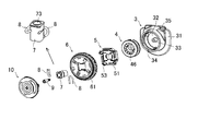
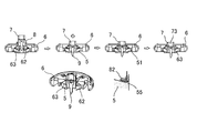
- FIG. 2 is an exploded perspective view showing components of the shoelace winding device embodying the present invention.
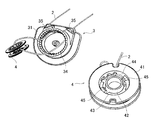
- FIG. 3 is a perspective view showing a base member and a reel of a shoelace winding device embodying the present invention.
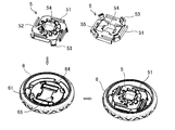
- FIG. 4 is a perspective view showing a dial and a stopper member of a shoelace winding device embodying the present invention.
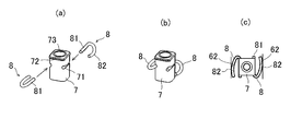
- FIG. 5 shows a shaft member and a spring member of a shoelace winding device embodying the present invention
- (a) and (b) are perspective views
- (c) are plan views.
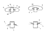
- FIG. 6 is a cross-sectional view showing a state when the shaft member is assembled to the dial of the shoelace winding device embodying the present invention.
- FIG. 7 is a side view showing the positional relationship between the dial and the shaft member of the shoelace winding device embodying the present invention and how the spring member rotates.
- the present invention provides a "reel for winding a shoelace, a base member having a reel storage unit for storing the reel, and a dial for rotationally driving the reel, the rotation of the dial being A dial having a stopper member for realizing a locked state that can be transmitted to the reel and a released state in which the reel is separated from the dial so that the reel can freely rotate, and the dial for attaching the dial to the base member A shaft member fixed to the base member, the shaft capable of being held and guided in a movable state between a lock position where the dial is brought close to the base member and a release position separated from the base member.
- a spring member having one end pivotally supported by a member and a bearing formed on a side of the shaft member in a direction orthogonal to the axial direction of the shaft member, the other end
- a shoelace winding device comprising a spring member that is always in contact with a locking portion provided on the inner surface of the dial, and wherein the dial can be switched from a locked state to a released state by moving from the locked position to the released position.
- the reversal position where the spring member is compressed most is set at a position between the lock position and the release position so that the direction in which the spring member is compressed is switched between the lock position and the release position.
- FIG. 1 shows a shoelace winding device 1 according to an embodiment of the present invention, and a shoe S equipped with the shoelace winding device 1 at a position corresponding to an ankle.
- the shoe S is a resin-coated metal.
- the upper part of the shoe S can be tightened by a shoelace 2 made of a wire made of metal.
- the shoelace winding device 1 includes a base member 3, a reel 4 for winding the shoelace 2, a stopper member 5 for controlling the rotation and stoppage of the reel, and a rotational drive for driving the reel 4.
- the base member 3 can fix the shoelace winding device 1 to the shoe S by sewing a thin plate-like U-shaped flange 31 to the shoe S, and rotates the reel 4.
- a bottomed cylindrical reel storage section 32 is provided for storage in a possible manner.
- the reel housing portion 32 is provided with a rotating shaft 33 for pivotally supporting the reel 4 at the bottom center, and a gear 34 is formed on the inner peripheral surface.
- the gear 34 forms a ratchet mechanism in cooperation with the claw 51 formed on the stopper member 5, and the cross section thereof is “saw saw” so that the claw 51 can move only in the direction of winding the shoelace 2 (forward rotation). It is formed in a “wave” shape.
- the base member 3 is formed with two shoelace pulling openings 35 opened at the bottom of the reel storage portion 32, and the shoelace 2 wound around the reel 4 is pulled out from the reel storage portion 32 to the outside. Be able to.
- the reel 4 includes a shoelace winding drum 41 for winding the shoelace 2, a rotating shaft portion 42 disposed inside the shoelace winding drum 41, and an inner periphery of the shoelace winding drum 41. And an annular groove 43 formed by the shoelace winding drum 41, the rotary shaft portion 42, and the annular portion 43.
- the annular portion 43 connects the surface and the outer peripheral surface of the rotational shaft portion 42. Yes.
- the rotation shaft 33 of the base member 3 is inserted on the inner surface side of the rotation shaft portion 42 so that the reel 4 can rotate in the reel storage portion 32.
- the groove 44 of the reel 4 is disposed on the side facing the bottom of the base member 3 (hereinafter referred to as “lower side” for convenience of explanation, and the opposite side is referred to as “upper side”).
- a locking projection 45 is provided in the groove portion 44 for holding the tip portion of the shoelace 2 introduced into the groove portion 44 from the outer peripheral surface side of the drum 41 and holding it in the groove portion 44. .
- a plurality of fins 46 are formed on the upper side of the reel 4 along the inner peripheral surface of the shoelace winding drum 41, and meshed with the fins 52 formed on the lower side of the stopper member 5. The rotation of the dial 6 can be transmitted to the reel.
- the stopper member 5 is fitted to the inner side (lower side) of the dial 6 by engaging mounting claws 53 projecting at the four corners thereof with engaging holes 61 formed through the dial 6. It is integrated with the dial 6 and is interposed between the reel 4 and the dial 6 so that the rotation of the dial 6 can be transmitted to the reel 4 and from the dial 6 so that the reel 4 can freely rotate. A release state in which the reel 4 is separated can be realized.
- the shaft member 7 is fixed to the base member 3 with a screw 9 so as to rotatably mount the integrated dial 6 and stopper member 5 to the base member 3. It is possible to hold and guide the dial 6 and the stopper member 5 in a movable state between a lock position where the dial 6 and the stopper member 5 are close to the base member 3 and a release position which is separated from the base member 3. ing.
- the shaft member 7 is formed in a quadrangular prism shape, and the spring member 8 is formed with respect to the bearing portion 71 formed by notching two opposing side portions of the shaft member in a direction orthogonal to the axial direction.
- the spring member 8 is pivotally supported so as to be rotatable. In other words, one spring member 8 is disposed at a position about 180 degrees apart from the shaft member 7.
- the shaft member 7 has a quadrangular prism shape, the strength of the bearing portion 71 can be increased and the shaft member 7 can be miniaturized. Further, the bearing portion 71 of the shaft member 7 is formed with the smallest inner diameter in the vicinity of the central portion in consideration of die cutting.
- the spring member 8 is entirely curved in a U-shape, and the curved spring portion 82 on the other end side contacts the locking portion 62 provided on the inner surface of the integrated dial 6 and stopper member 5. It comes to touch.
- the locking portion 62 with which the other end portion (spring portion 82) of the spring member 8 abuts is provided at the narrowest outer end portion of the spring housing space 63 formed in a wedge shape at the boundary portion between the dial 6 and the stopper member 5. It has been.
- the reel 4 can be switched from the locked state to the released state by moving the integrated dial 6 and the stopper member 5 from the locked position to the released position.
- the reversal position L where the spring portion 82 of the spring member 8 is compressed most toward the shaft member side is set at a position between the lock position and the release position.
- a disc-shaped cap 10 is fitted on the upper side of the dial 6 so that dust or the like does not enter the shoelace winding device 1.
- a through hole 11 is formed at the center of the cap 10, and the screw 9 on the inner side (lower side) of the cap 10 is operated through the through hole 11 so that the reel 4, the dial 6, The shaft member 7 can be removed.
- nylon is processed with a swaging machine on a wire rope in which 49 strands of stainless steel with a diameter of 0.11 to 0.13 mm are twisted. What was coat
- covered with resin can be used suitably.
- the stopper member 5 is fitted to the inside (lower side) of the dial 6 so that the stopper member 5 is integrated with the dial 6 and the shaft member 7 and the spring member 8 are assembled to them.
- the spring member 8 is inserted into the substantially square shaft hole 64 formed in the dial 6 and the substantially square shaft hole 54 formed in the stopper member 5.
- the spring portion 82 of the spring member 8 is inserted into the spring accommodating space 63 from the expanded portion where the shaft hole 64 of the dial 6 is expanded, and the spring portion 82 is further narrowest from the inner end side of the spring accommodating space 63 to the outer end. It is guided so as to turn to the part side and is assembled to the dial 6. Since the flange 72 formed on the upper end portion of the shaft member 7 contacts the locking step portion 65 formed on the edge of the shaft hole 64 of the dial 6, the dial 6 does not come off the shaft member 7.
- the spring portion 82 of the spring member 8 is guided so as to rotate from the inner end side of the spring accommodating space 63 toward the outer end narrowest portion side, on the edge of the shaft hole 54 of the stopper member 5 (on the dial side). This is because the inclined surface 55 facing the) is formed.
- the shoelace winding device 1 can be assembled by fitting the cap 10 into the dial 6.
- a screwdriver is inserted from the through hole 11 of the cap 10 and the screw 9 is removed, so that the assembled stopper member 5, dial 6, shaft
- the member 7 and the spring member 8 can be removed from the base member 3.
- the stopper member 5, the dial 6, the shaft member 7, and the spring member 8 are used. It can be removed from the base member 3 while being assembled, which is very effective in improving the efficiency of maintenance or repair work.
- each member in the shoelace winding device 1 of the present embodiment the following materials are used as an example in consideration of strength, durability, elasticity, and the like, but are limited to these materials. It is not something.
- Base member 3 ... nylon reel 4, stopper member 5, shaft member 7 ... POM (polyacetal) Dial 6 ... Nylon and TPE (thermoplastic elastomer) around it Spring member 8 ... Stainless steel Screw 9 ... Carbon steel Cap 10 ... ABS resin
- a method of using the shoelace winding device 1 configured as described above will be described.
- the dial 6 of the shoelace winding device 1 is rotated at the locked position where the dial 6 is brought close to the base member 3, and the shoelace 2 is reeled 4. Wrap around.
- the reel 4 does not rotate in the direction in which the shoelace 2 is loosened.
- the reverse position L where the spring member 8 is most compressed is set at a position between the lock position and the release position, the spring member 8 is located on the left side of FIG. 7 when the dial 6 is in the lock position. The dial 6 is held in the locked position. At this time, the spring member 8 faces the direction of lifting the shaft member 7 and pressing the dial 6 downward.
- the dial 6 of the shoelace winding device 1 is pulled upward.
- the spring member 8 is compressed, and by pulling the dial 6 further upward against the repulsive force, the reversing position L where the spring member 8 is most compressed is exceeded, and the lock position and the release position are
- the dial 6 is moved to the release position away from the base member 3 (state shown on the right side of FIG. 7).
- the spring member 8 faces the direction in which the shaft member 7 is pressed down and the dial 6 is lifted up.
- the other end portion (spring portion 82) of the spring member 8 is always in contact with a locking portion 64 provided on the inner surface of the dial 6, and wear of parts can be prevented. Note that “always contact” is intended to improve the reliability, durability, and operability of the shoelace winding device 1 and to eliminate the rattling of the dial 6. It is not intended to completely exclude the presence of some “play” as long as the operation of the taking device 1 is not hindered.
- the “dial” is not particularly limited as long as it functions as an operation unit for rotationally driving the reel 4, and may be polygonal. .
- the present invention is not limited to the shoelace winding device 1 for fastening the wired shoelace 2 as in the illustrated example, but the shoelace winding for fastening the shoelace 2 for fastening different portions of the shoe S. It may be implemented in an apparatus.
- each part of the shoelace winding device may be changed as appropriate without departing from the spirit of the present invention.
- the present invention is small and light, has excellent durability, operability and maintainability, and can be suitably used as a shoelace winding device that can be easily used for a wide variety of shoes.
Landscapes
- Footwear And Its Accessory, Manufacturing Method And Apparatuses (AREA)
Priority Applications (7)
| Application Number | Priority Date | Filing Date | Title |
|---|---|---|---|
| CN201380027506.5A CN104540411B (zh) | 2013-06-18 | 2013-10-17 | 鞋带卷取装置 |
| US14/405,733 US9635906B2 (en) | 2013-06-18 | 2013-10-17 | Shoelace winding device |
| HK15104394.7A HK1203782B (en) | 2013-06-18 | 2013-10-17 | Shoelace winding device |
| CA2876000A CA2876000C (en) | 2013-06-18 | 2013-10-17 | Shoelace winding device |
| AU2013391431A AU2013391431B2 (en) | 2013-06-18 | 2013-10-17 | Shoelace winding device |
| KR1020147021604A KR101705017B1 (ko) | 2013-06-18 | 2013-10-17 | 신발끈 권취장치 |
| EP13886148.9A EP3011856B1 (en) | 2013-06-18 | 2013-10-17 | Shoelace winding device |
Applications Claiming Priority (2)
| Application Number | Priority Date | Filing Date | Title |
|---|---|---|---|
| JP2013-127574 | 2013-06-18 | ||
| JP2013127574A JP6087219B2 (ja) | 2013-06-18 | 2013-06-18 | 靴紐巻取装置 |
Publications (1)
| Publication Number | Publication Date |
|---|---|
| WO2014203415A1 true WO2014203415A1 (ja) | 2014-12-24 |
Family
ID=52104174
Family Applications (1)
| Application Number | Title | Priority Date | Filing Date |
|---|---|---|---|
| PCT/JP2013/078116 WO2014203415A1 (ja) | 2013-06-18 | 2013-10-17 | 靴紐巻取装置 |
Country Status (9)
Families Citing this family (35)
| Publication number | Priority date | Publication date | Assignee | Title |
|---|---|---|---|---|
| CN104003064B (zh) * | 2013-02-26 | 2016-06-29 | 国基电子(上海)有限公司 | 束线装置 |
| ITTV20130045A1 (it) * | 2013-04-09 | 2014-10-10 | Northwave Srl | Dispositivo di serraggio |
| JP6406919B2 (ja) | 2014-08-11 | 2018-10-17 | 株式会社ジャパーナ | 靴紐巻取装置の取付構造 |
| JP6450584B2 (ja) * | 2014-12-22 | 2019-01-09 | 株式会社ジャパーナ | 巻取装置及びそれを備えた靴 |
| US10264852B2 (en) | 2015-01-14 | 2019-04-23 | Sug Whan Kim | String winding and unwinding apparatus |
| KR101569461B1 (ko) * | 2015-01-14 | 2015-11-18 | 스피어다인 주식회사 | 스트링 권취 및 권출 장치 |
| JP6687307B2 (ja) * | 2015-10-23 | 2020-04-22 | 株式会社ジャパーナ | 巻取装置 |
| CN106919220B (zh) * | 2015-12-25 | 2018-06-05 | 陈金柱 | 紧固装置 |
| US9861164B2 (en) * | 2016-03-15 | 2018-01-09 | Nike, Inc. | Tensioning system and reel member for an article of footwear |
| JP2017169773A (ja) * | 2016-03-23 | 2017-09-28 | 株式会社ジャパーナ | 靴 |
| JP6810530B2 (ja) * | 2016-04-04 | 2021-01-06 | 株式会社アルペン | 巻取装置 |
| CN106428993B (zh) * | 2016-07-29 | 2019-03-08 | 温州职业技术学院 | 一种捆扎包装装置 |
| JP6882827B2 (ja) | 2016-08-10 | 2021-06-02 | 株式会社アルペン | 巻取装置 |
| US10588381B2 (en) * | 2016-11-21 | 2020-03-17 | Under Armour, Inc. | Footwear with internal harness |
| CN106723663B (zh) * | 2017-01-24 | 2019-05-24 | 深圳市悠宁科技有限公司 | 鞋带收放装置 |
| JP6881993B2 (ja) * | 2017-02-01 | 2021-06-02 | 株式会社アルペン | 紐巻取装置を備えた物品 |
| JP2018121920A (ja) * | 2017-02-01 | 2018-08-09 | 株式会社ジャパーナ | 巻取装置 |
| DE102018201019A1 (de) | 2017-02-28 | 2018-08-30 | Fidlock Gmbh | Verschlussvorrichtung mit einem Wickelelement |
| DE102018201021A1 (de) * | 2017-11-14 | 2019-05-16 | Fidlock Gmbh | Verschlussvorrichtung mit einem Wickelelement |
| KR102026210B1 (ko) * | 2019-04-23 | 2019-09-27 | 한양대학교 산학협력단 | 조그 다이얼을 이용한 의수 |
| WO2020247645A1 (en) | 2019-06-05 | 2020-12-10 | Hurley Garrett Ray | Adjustable closure devices with handle and locking mechanisms |
| DE102019217036A1 (de) * | 2019-11-05 | 2021-05-06 | Fidlock Gmbh | Verschlussvorrichtung mit einem Drehelement |
| US20220175089A1 (en) * | 2020-12-04 | 2022-06-09 | Boa Technology Inc. | Reel based closure device |
| DE112022002149T5 (de) * | 2021-04-15 | 2024-01-25 | Pride Manufacturing Company, Llc | Systeme und verfahren für eine drehknopfabdeckung für einen drehverschluss für einen schuh |
| EP4144250A1 (en) * | 2021-07-19 | 2023-03-08 | Shishi Senke Intelligent Technology Co., Ltd. | Rotary push-pull rope winder and shoes |
| TWM623553U (zh) * | 2021-08-18 | 2022-02-21 | 陳金柱 | 緊固裝置 |
| US12108843B2 (en) * | 2021-08-18 | 2024-10-08 | Chin-Chu Chen | Fastening device |
| US12295894B2 (en) | 2021-11-09 | 2025-05-13 | Allen Medical Systems, Inc. | Surgical traction boot having resilient heel pad and medial and lateral straps |
| JP7126286B1 (ja) | 2021-11-18 | 2022-08-26 | 有限会社Vital-Fuss-Kochi | 紐靴及び紐靴の緊締方法 |
| CN116509108A (zh) | 2022-01-21 | 2023-08-01 | 深圳市爱康伟达智能医疗科技有限公司 | 一种新型的系带装置及其止逆机构 |
| US20250134278A1 (en) * | 2022-07-19 | 2025-05-01 | Kerata Inc. | Baby carrier |
| TW202406824A (zh) * | 2022-08-01 | 2024-02-16 | 蔡志信 | 緊固裝置 |
| CN115813647B (zh) * | 2022-11-04 | 2024-12-03 | 绵阳市骨科医院 | 一种临床治疗用可约束手套 |
| CN115744503A (zh) * | 2022-11-21 | 2023-03-07 | 江馨月 | 一种正反转松紧系绳装置 |
| CN120379917A (zh) * | 2024-02-01 | 2025-07-25 | 深圳市爱旋科技有限公司 | 可微调绳线收放装置及物品 |
Citations (4)
| Publication number | Priority date | Publication date | Assignee | Title |
|---|---|---|---|---|
| JP2010148927A (ja) | 1999-09-02 | 2010-07-08 | Boa Technology Inc | 履物の紐掛けシステム |
| US20110191992A1 (en) | 2010-02-11 | 2011-08-11 | Chin-Chu Chen | Stepless fastening device |
| WO2011137405A2 (en) | 2010-04-30 | 2011-11-03 | Boa Technology, Inc. | Reel based lacing system |
| JP2013022467A (ja) * | 2011-07-25 | 2013-02-04 | Shin Kyung Chemical Co Ltd | 靴紐の締め装置(apparatusforfasteningshoelace) |
Family Cites Families (36)
| Publication number | Priority date | Publication date | Assignee | Title |
|---|---|---|---|---|
| JPS583428Y2 (ja) | 1978-01-17 | 1983-01-20 | 東成産業株式会社 | 物干し用ハンガ−ロ−プ |
| IT1193578B (it) | 1981-01-28 | 1988-07-08 | Nordica Spa | Dispositivo di chiusura particolarmente per scarponi da sci |
| IT1184540B (it) * | 1985-05-06 | 1987-10-28 | Nordica Spa | Scarpone da sci con dispositivo di chiusura dei gambali |
| DE3926514A1 (de) | 1989-08-10 | 1991-02-14 | Weinmann & Co Kg | Drehverschluss fuer einen sportschuh, insbesondere einen skischuh |
| US5157813A (en) | 1991-10-31 | 1992-10-27 | William Carroll | Shoelace tensioning device |
| DE9200982U1 (de) | 1992-01-28 | 1993-05-27 | PUMA AG Rudolf Dassler Sport, 8522 Herzogenaurach | Schuh mit einem Zentralverschluß |
| DE4240916C1 (de) | 1992-12-04 | 1993-10-07 | Jungkind Roland | Schuhverschluß |
| DE59309371D1 (de) | 1993-11-04 | 1999-03-25 | Am Srl | Spannvorrichtung für einen Sportschuh |
| US20060156517A1 (en) | 1997-08-22 | 2006-07-20 | Hammerslag Gary R | Reel based closure system |
| US5934599A (en) | 1997-08-22 | 1999-08-10 | Hammerslag; Gary R. | Footwear lacing system |
| AU2001290878A1 (en) | 2000-09-19 | 2002-04-02 | Anna B. Freed | Closure |
| TW569680U (en) * | 2003-03-07 | 2004-01-01 | Morning Internat Co Ltd | Bootlace tighten structure summary of the invention |
| DE10335940A1 (de) | 2003-08-04 | 2005-03-10 | Japana Co | Spannvorrichtung für Zugkabel, insbesondere von Zugkabel-Schnürungen an Schuhen |
| US20110167543A1 (en) | 2004-05-07 | 2011-07-14 | Enventys, Llc | Adjustable protective apparel |
| US7516914B2 (en) | 2004-05-07 | 2009-04-14 | Enventys, Llc | Bi-directional device |
| CN101193568B (zh) | 2004-10-29 | 2011-11-30 | 博技术有限公司 | 基于卷轴的闭合系统及使用该系统的鞋类物品 |
| KR100598627B1 (ko) * | 2005-06-27 | 2006-07-13 | 주식회사 신경 | 신발끈 조임기 |
| DE102005037967A1 (de) | 2005-08-11 | 2007-02-15 | Head Germany Gmbh | Drehverschluss für einen Schuh |
| WO2007081822A2 (en) | 2006-01-06 | 2007-07-19 | Boa Technology, Inc. | Rough and fine adjustment closure system |
| CN201015448Y (zh) * | 2007-02-02 | 2008-02-06 | 盟汉塑胶股份有限公司 | 鞋卷线器 |
| CN201029494Y (zh) * | 2007-03-29 | 2008-03-05 | 董兵秋 | 改良鞋带锁扣 |
| CN101977525B (zh) | 2008-01-18 | 2012-12-12 | 博技术有限公司 | 用于物件的收紧系统和用于将两个物体彼此拉近或拉开的方法 |
| US8468657B2 (en) | 2008-11-21 | 2013-06-25 | Boa Technology, Inc. | Reel based lacing system |
| US8245371B2 (en) * | 2009-04-01 | 2012-08-21 | Chin Chu Chen | String securing device |
| US8707486B2 (en) * | 2010-02-16 | 2014-04-29 | Allen Medical Systems, Inc. | Lacing system to secure a limb in a surgical support apparatus |
| US9375053B2 (en) * | 2012-03-15 | 2016-06-28 | Boa Technology, Inc. | Tightening mechanisms and applications including the same |
| CA2804759C (en) | 2010-07-01 | 2019-06-18 | Boa Technology, Inc. | Braces using lacing systems |
| JP5727771B2 (ja) | 2010-12-08 | 2015-06-03 | 株式会社ジャパーナ | 靴ひもの巻取装置 |
| US8353087B2 (en) * | 2011-03-07 | 2013-01-15 | Chin-Chu Chen | Closure device |
| KR101107372B1 (ko) | 2011-05-30 | 2012-01-19 | 소윤서 | 줄 길이 조절장치 |
| US9101181B2 (en) * | 2011-10-13 | 2015-08-11 | Boa Technology Inc. | Reel-based lacing system |
| CA2874232C (en) * | 2012-11-30 | 2018-02-27 | Puma SE | Rotary closure for a shoe |
| EP2948014B1 (en) * | 2013-01-28 | 2019-06-26 | Boa Technology Inc. | Lace fixation assembly and system |
| KR101506676B1 (ko) | 2013-09-03 | 2015-03-30 | 주식회사 신경 | 와이어 조임장치 및 그의 장착방법 |
| TWI561453B (en) | 2014-02-17 | 2016-12-11 | Chin Chu Chen | A device for tightening and loosening a lace |
| US9364054B2 (en) * | 2014-04-09 | 2016-06-14 | Tristan S. Gittens | Accessory cinching device |
-
2013
- 2013-06-18 JP JP2013127574A patent/JP6087219B2/ja active Active
- 2013-10-17 AU AU2013391431A patent/AU2013391431B2/en not_active Ceased
- 2013-10-17 CA CA2876000A patent/CA2876000C/en not_active Expired - Fee Related
- 2013-10-17 CN CN201380027506.5A patent/CN104540411B/zh active Active
- 2013-10-17 US US14/405,733 patent/US9635906B2/en active Active
- 2013-10-17 KR KR1020147021604A patent/KR101705017B1/ko not_active Expired - Fee Related
- 2013-10-17 EP EP13886148.9A patent/EP3011856B1/en active Active
- 2013-10-17 WO PCT/JP2013/078116 patent/WO2014203415A1/ja active Application Filing
-
2014
- 2014-06-04 TW TW103119313A patent/TWI625103B/zh not_active IP Right Cessation
Patent Citations (4)
| Publication number | Priority date | Publication date | Assignee | Title |
|---|---|---|---|---|
| JP2010148927A (ja) | 1999-09-02 | 2010-07-08 | Boa Technology Inc | 履物の紐掛けシステム |
| US20110191992A1 (en) | 2010-02-11 | 2011-08-11 | Chin-Chu Chen | Stepless fastening device |
| WO2011137405A2 (en) | 2010-04-30 | 2011-11-03 | Boa Technology, Inc. | Reel based lacing system |
| JP2013022467A (ja) * | 2011-07-25 | 2013-02-04 | Shin Kyung Chemical Co Ltd | 靴紐の締め装置(apparatusforfasteningshoelace) |
Also Published As
| Publication number | Publication date |
|---|---|
| EP3011856A1 (en) | 2016-04-27 |
| JP2015000293A (ja) | 2015-01-05 |
| US20160262496A1 (en) | 2016-09-15 |
| EP3011856A4 (en) | 2017-02-15 |
| KR101705017B1 (ko) | 2017-02-09 |
| TWI625103B (zh) | 2018-06-01 |
| AU2013391431A1 (en) | 2015-01-22 |
| CN104540411A (zh) | 2015-04-22 |
| TW201509325A (zh) | 2015-03-16 |
| AU2013391431B2 (en) | 2017-02-02 |
| CA2876000C (en) | 2017-01-17 |
| HK1203782A1 (zh) | 2015-11-06 |
| CA2876000A1 (en) | 2014-12-24 |
| US9635906B2 (en) | 2017-05-02 |
| EP3011856B1 (en) | 2019-06-12 |
| JP6087219B2 (ja) | 2017-03-01 |
| CN104540411B (zh) | 2016-04-20 |
| KR20150032515A (ko) | 2015-03-26 |
Similar Documents
| Publication | Publication Date | Title |
|---|---|---|
| JP6087219B2 (ja) | 靴紐巻取装置 | |
| JP6105404B2 (ja) | 靴紐巻取用リール | |
| CN109640728B (zh) | 卷取装置 | |
| JP4473301B2 (ja) | チェーン伝動用テンショナレバー | |
| WO2017175586A1 (ja) | 巻取装置 | |
| WO2018143060A1 (ja) | 巻取装置 | |
| WO2017068937A1 (ja) | 巻取装置 | |
| HK1203782B (en) | Shoelace winding device | |
| HK1203783B (en) | Shoelace winding reel | |
| HK40007058A (en) | Winding device | |
| HK40007058B (zh) | 卷取装置 | |
| JP2011169343A (ja) | ワイヤ操作装置 |
Legal Events
| Date | Code | Title | Description |
|---|---|---|---|
| WWE | Wipo information: entry into national phase |
Ref document number: 201380027506.5 Country of ref document: CN |
|
| ENP | Entry into the national phase |
Ref document number: 20147021604 Country of ref document: KR Kind code of ref document: A |
|
| ENP | Entry into the national phase |
Ref document number: 2876000 Country of ref document: CA |
|
| WWE | Wipo information: entry into national phase |
Ref document number: 14405733 Country of ref document: US Ref document number: 2013886148 Country of ref document: EP Ref document number: 2013391431 Country of ref document: AU |
|
| 121 | Ep: the epo has been informed by wipo that ep was designated in this application |
Ref document number: 13886148 Country of ref document: EP Kind code of ref document: A1 |
|
| NENP | Non-entry into the national phase |
Ref country code: DE |