WO2014203415A1 - Shoelace winding device - Google Patents
Shoelace winding device Download PDFInfo
- Publication number
- WO2014203415A1 WO2014203415A1 PCT/JP2013/078116 JP2013078116W WO2014203415A1 WO 2014203415 A1 WO2014203415 A1 WO 2014203415A1 JP 2013078116 W JP2013078116 W JP 2013078116W WO 2014203415 A1 WO2014203415 A1 WO 2014203415A1
- Authority
- WO
- WIPO (PCT)
- Prior art keywords
- dial
- reel
- spring
- winding device
- shoelace
- Prior art date
Links
Images

Classifications
-
- A—HUMAN NECESSITIES
- A43—FOOTWEAR
- A43C—FASTENINGS OR ATTACHMENTS OF FOOTWEAR; LACES IN GENERAL
- A43C11/00—Other fastenings specially adapted for shoes
- A43C11/16—Fastenings secured by wire, bolts, or the like
- A43C11/165—Fastenings secured by wire, bolts, or the like characterised by a spool, reel or pulley for winding up cables, laces or straps by rotation
-
- A—HUMAN NECESSITIES
- A43—FOOTWEAR
- A43C—FASTENINGS OR ATTACHMENTS OF FOOTWEAR; LACES IN GENERAL
- A43C11/00—Other fastenings specially adapted for shoes
- A43C11/16—Fastenings secured by wire, bolts, or the like
-
- A—HUMAN NECESSITIES
- A43—FOOTWEAR
- A43B—CHARACTERISTIC FEATURES OF FOOTWEAR; PARTS OF FOOTWEAR
- A43B11/00—Footwear with arrangements to facilitate putting-on or removing, e.g. with straps
-
- A—HUMAN NECESSITIES
- A43—FOOTWEAR
- A43B—CHARACTERISTIC FEATURES OF FOOTWEAR; PARTS OF FOOTWEAR
- A43B23/00—Uppers; Boot legs; Stiffeners; Other single parts of footwear
- A43B23/02—Uppers; Boot legs
-
- A—HUMAN NECESSITIES
- A43—FOOTWEAR
- A43C—FASTENINGS OR ATTACHMENTS OF FOOTWEAR; LACES IN GENERAL
- A43C7/00—Holding-devices for laces
Definitions
- the present invention relates to a shoelace winding device, and is not limited to boots for skiing, snowboarding, skating, mountain climbing, motorcycle riding, athletic shoes used for golf, jogging, etc.
- the present invention relates to a shoelace winding device suitable for tightening a shoelace of a simple shoe.
- the shoelace is tightened by the dial by sliding the resin protrusion (sawtooth washer) and engaging it with either a “connection recess” or “non-connection recess”.
- An operation for switching between a locked state in which the shoelace can be released and a release state in which the shoelace can be released from being tightened is enabled.
- connection recess Even in the embodiment in which a spring made of a steel wire is used in place of the protrusion and the spring is moved between the “connection recess” and the “non-connection recess”, the “connection recess” and the “non-connection” are also used. There is a problem that the “mountains” between the “dents” are worn and lack durability and reliability.
- the problem to be solved by the present invention is to switch between a locked state in which the shoelace can be tightened and a release state in which the shoelace can be unfastened in the conventional shoelace winding device. Repeating is likely to cause failure due to wear, and in order to improve strength and durability, it is necessary to use a lot of metal parts or make resin parts large.
- the object of the present invention is small and lightweight , Durability and reliability can be improved, as well as easy to disassemble during assembly and repair, excellent operability, and shoelace winding that can be used for a wider variety of shoes To provide an apparatus.
- the present invention provides a "reel for winding a shoelace, a base member having a reel storage unit for storing the reel, and a dial for rotationally driving the reel, the rotation of the dial being A dial having a stopper member for realizing a locked state that can be transmitted to the reel and a released state in which the reel is separated from the dial so that the reel can freely rotate, and the dial for attaching the dial to the base member A shaft member fixed to the base member, the shaft capable of being held and guided in a movable state between a lock position where the dial is brought close to the base member and a release position separated from the base member.
- a spring member having one end pivotally supported by a member and a bearing formed on a side of the shaft member in a direction orthogonal to the axial direction of the shaft member, the other end And a spring member in contact at all times and the locking portion provided on the inner surface of the dial,
- a shoelace winding device that can be switched from a locked state of a reel to a released state by moving the dial from a locked position to a released position, wherein the spring member is at a position between the locked position and the released position.
- a shoelace winding device wherein a reversal position to be compressed is set, and a direction in which the spring member is compressed is switched between the lock position and the release position.
- the stopper member fits inside the dial and is integrated with the dial, and the locking portion with which the other end of the spring member abuts is wedge-shaped at the boundary between the dial and the stopper member. You may provide in the outer end narrowest part of the formed spring accommodation space.
- the other end portion of the spring member extends from the extended portion where the shaft hole of the dial is expanded into the spring accommodating space.
- the other end portion may be inserted and guided so as to rotate from the inner end side of the spring accommodating space to the outer end narrowest portion side and assembled to the dial.
- the spring member is a spring member that is curved in a substantially U shape, and a linear shaft portion on one end side thereof is formed on a side portion of the shaft member in a direction perpendicular to the axial direction of the shaft member.
- the spring portion on the other end side that is pivotally supported by the formed bearing portion and that is curved may abut against the locking portion.
- one spring member may be disposed at a position about 180 degrees apart from the shaft member.
- the other end of the spring member whose one end is pivotally supported is always in contact with a locking portion provided on the inner surface of the dial when the dial is switched between the locked state and the released state. Therefore, when the dial moves from the lock position to the release position, the position where the spring member and the parts such as the dial are in contact does not change, so that the spring member and the parts such as the dial are prevented from rubbing and wearing. Can do.
- the reverse position where the spring member is most compressed is set at a position between the lock position and the release position of the dial, the spring member is compressed to move the dial from the lock position to the release position. Therefore, it is possible to prevent the dial from being inadvertently moved from the lock position to the release position. Furthermore, since the direction in which the spring member is compressed is switched between the lock position and the release position of the dial, the operability is excellent and the state of the dial can be clearly grasped.
- the stopper member By fitting the stopper member inside the dial so as to be integrated with the dial, it is possible to easily provide a component having a complicated shape. Furthermore, by providing the locking portion with which the other end portion of the spring member abuts at the narrowest outer end portion of the spring accommodating space formed in a wedge shape at the boundary portion between the dial and the stopper member, the spring member is accommodated. The reliability and durability of the device can be improved, and the operating range of the spring member can be correctly regulated.
- the other end portion of the spring member extends from the extended portion where the shaft hole of the dial is expanded into the spring accommodating space.
- the spring member is inserted into the dial and guided to be pivoted from the inner end side to the outer end narrowest portion side of the spring accommodating space and assembled to the dial.
- the spring member can be easily assembled by simply pushing it in.
- the spring member is a spring member that is formed in a substantially U-shape, and a linear shaft portion on one end side thereof is formed on a side portion of the shaft member in a direction orthogonal to the axial direction of the shaft member.
- the spring portion that is pivotally supported by the formed bearing portion and curved on the other end side comes into contact with the locking portion, so that the spring portion can rotate around the shaft portion.
- the spring portion is curved, the spring portion and the locking portion come into smooth contact when the spring member is compressively deformed, and the spring member can be smoothly deformed. That is, the compression operation of the spring member can be performed smoothly, and the operability can be improved when changing the dial position.
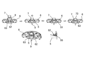
- FIG. 1 is a perspective view of a shoe equipped with a shoelace winding device embodying the present invention, and a cross-sectional view of the shoelace winding device, wherein (a) shows a state where a dial is in a locked position. (B) is a figure which shows the state which has a dial in a cancellation
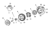
- FIG. 2 is an exploded perspective view showing components of the shoelace winding device embodying the present invention.
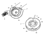
- FIG. 3 is a perspective view showing a base member and a reel of a shoelace winding device embodying the present invention.
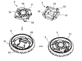
- FIG. 4 is a perspective view showing a dial and a stopper member of a shoelace winding device embodying the present invention.
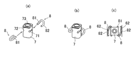
- FIG. 5 shows a shaft member and a spring member of a shoelace winding device embodying the present invention
- (a) and (b) are perspective views
- (c) are plan views.
- FIG. 6 is a cross-sectional view showing a state when the shaft member is assembled to the dial of the shoelace winding device embodying the present invention.
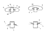
- FIG. 7 is a side view showing the positional relationship between the dial and the shaft member of the shoelace winding device embodying the present invention and how the spring member rotates.
- the present invention provides a "reel for winding a shoelace, a base member having a reel storage unit for storing the reel, and a dial for rotationally driving the reel, the rotation of the dial being A dial having a stopper member for realizing a locked state that can be transmitted to the reel and a released state in which the reel is separated from the dial so that the reel can freely rotate, and the dial for attaching the dial to the base member A shaft member fixed to the base member, the shaft capable of being held and guided in a movable state between a lock position where the dial is brought close to the base member and a release position separated from the base member.
- a spring member having one end pivotally supported by a member and a bearing formed on a side of the shaft member in a direction orthogonal to the axial direction of the shaft member, the other end
- a shoelace winding device comprising a spring member that is always in contact with a locking portion provided on the inner surface of the dial, and wherein the dial can be switched from a locked state to a released state by moving from the locked position to the released position.
- the reversal position where the spring member is compressed most is set at a position between the lock position and the release position so that the direction in which the spring member is compressed is switched between the lock position and the release position.
- FIG. 1 shows a shoelace winding device 1 according to an embodiment of the present invention, and a shoe S equipped with the shoelace winding device 1 at a position corresponding to an ankle.
- the shoe S is a resin-coated metal.
- the upper part of the shoe S can be tightened by a shoelace 2 made of a wire made of metal.
- the shoelace winding device 1 includes a base member 3, a reel 4 for winding the shoelace 2, a stopper member 5 for controlling the rotation and stoppage of the reel, and a rotational drive for driving the reel 4.
- the base member 3 can fix the shoelace winding device 1 to the shoe S by sewing a thin plate-like U-shaped flange 31 to the shoe S, and rotates the reel 4.
- a bottomed cylindrical reel storage section 32 is provided for storage in a possible manner.
- the reel housing portion 32 is provided with a rotating shaft 33 for pivotally supporting the reel 4 at the bottom center, and a gear 34 is formed on the inner peripheral surface.
- the gear 34 forms a ratchet mechanism in cooperation with the claw 51 formed on the stopper member 5, and the cross section thereof is “saw saw” so that the claw 51 can move only in the direction of winding the shoelace 2 (forward rotation). It is formed in a “wave” shape.
- the base member 3 is formed with two shoelace pulling openings 35 opened at the bottom of the reel storage portion 32, and the shoelace 2 wound around the reel 4 is pulled out from the reel storage portion 32 to the outside. Be able to.
- the reel 4 includes a shoelace winding drum 41 for winding the shoelace 2, a rotating shaft portion 42 disposed inside the shoelace winding drum 41, and an inner periphery of the shoelace winding drum 41. And an annular groove 43 formed by the shoelace winding drum 41, the rotary shaft portion 42, and the annular portion 43.
- the annular portion 43 connects the surface and the outer peripheral surface of the rotational shaft portion 42. Yes.
- the rotation shaft 33 of the base member 3 is inserted on the inner surface side of the rotation shaft portion 42 so that the reel 4 can rotate in the reel storage portion 32.
- the groove 44 of the reel 4 is disposed on the side facing the bottom of the base member 3 (hereinafter referred to as “lower side” for convenience of explanation, and the opposite side is referred to as “upper side”).
- a locking projection 45 is provided in the groove portion 44 for holding the tip portion of the shoelace 2 introduced into the groove portion 44 from the outer peripheral surface side of the drum 41 and holding it in the groove portion 44. .
- a plurality of fins 46 are formed on the upper side of the reel 4 along the inner peripheral surface of the shoelace winding drum 41, and meshed with the fins 52 formed on the lower side of the stopper member 5. The rotation of the dial 6 can be transmitted to the reel.
- the stopper member 5 is fitted to the inner side (lower side) of the dial 6 by engaging mounting claws 53 projecting at the four corners thereof with engaging holes 61 formed through the dial 6. It is integrated with the dial 6 and is interposed between the reel 4 and the dial 6 so that the rotation of the dial 6 can be transmitted to the reel 4 and from the dial 6 so that the reel 4 can freely rotate. A release state in which the reel 4 is separated can be realized.
- the shaft member 7 is fixed to the base member 3 with a screw 9 so as to rotatably mount the integrated dial 6 and stopper member 5 to the base member 3. It is possible to hold and guide the dial 6 and the stopper member 5 in a movable state between a lock position where the dial 6 and the stopper member 5 are close to the base member 3 and a release position which is separated from the base member 3. ing.
- the shaft member 7 is formed in a quadrangular prism shape, and the spring member 8 is formed with respect to the bearing portion 71 formed by notching two opposing side portions of the shaft member in a direction orthogonal to the axial direction.
- the spring member 8 is pivotally supported so as to be rotatable. In other words, one spring member 8 is disposed at a position about 180 degrees apart from the shaft member 7.
- the shaft member 7 has a quadrangular prism shape, the strength of the bearing portion 71 can be increased and the shaft member 7 can be miniaturized. Further, the bearing portion 71 of the shaft member 7 is formed with the smallest inner diameter in the vicinity of the central portion in consideration of die cutting.
- the spring member 8 is entirely curved in a U-shape, and the curved spring portion 82 on the other end side contacts the locking portion 62 provided on the inner surface of the integrated dial 6 and stopper member 5. It comes to touch.
- the locking portion 62 with which the other end portion (spring portion 82) of the spring member 8 abuts is provided at the narrowest outer end portion of the spring housing space 63 formed in a wedge shape at the boundary portion between the dial 6 and the stopper member 5. It has been.
- the reel 4 can be switched from the locked state to the released state by moving the integrated dial 6 and the stopper member 5 from the locked position to the released position.
- the reversal position L where the spring portion 82 of the spring member 8 is compressed most toward the shaft member side is set at a position between the lock position and the release position.
- a disc-shaped cap 10 is fitted on the upper side of the dial 6 so that dust or the like does not enter the shoelace winding device 1.
- a through hole 11 is formed at the center of the cap 10, and the screw 9 on the inner side (lower side) of the cap 10 is operated through the through hole 11 so that the reel 4, the dial 6, The shaft member 7 can be removed.
- nylon is processed with a swaging machine on a wire rope in which 49 strands of stainless steel with a diameter of 0.11 to 0.13 mm are twisted. What was coat
- covered with resin can be used suitably.
- the stopper member 5 is fitted to the inside (lower side) of the dial 6 so that the stopper member 5 is integrated with the dial 6 and the shaft member 7 and the spring member 8 are assembled to them.
- the spring member 8 is inserted into the substantially square shaft hole 64 formed in the dial 6 and the substantially square shaft hole 54 formed in the stopper member 5.
- the spring portion 82 of the spring member 8 is inserted into the spring accommodating space 63 from the expanded portion where the shaft hole 64 of the dial 6 is expanded, and the spring portion 82 is further narrowest from the inner end side of the spring accommodating space 63 to the outer end. It is guided so as to turn to the part side and is assembled to the dial 6. Since the flange 72 formed on the upper end portion of the shaft member 7 contacts the locking step portion 65 formed on the edge of the shaft hole 64 of the dial 6, the dial 6 does not come off the shaft member 7.
- the spring portion 82 of the spring member 8 is guided so as to rotate from the inner end side of the spring accommodating space 63 toward the outer end narrowest portion side, on the edge of the shaft hole 54 of the stopper member 5 (on the dial side). This is because the inclined surface 55 facing the) is formed.
- the shoelace winding device 1 can be assembled by fitting the cap 10 into the dial 6.
- a screwdriver is inserted from the through hole 11 of the cap 10 and the screw 9 is removed, so that the assembled stopper member 5, dial 6, shaft
- the member 7 and the spring member 8 can be removed from the base member 3.
- the stopper member 5, the dial 6, the shaft member 7, and the spring member 8 are used. It can be removed from the base member 3 while being assembled, which is very effective in improving the efficiency of maintenance or repair work.
- each member in the shoelace winding device 1 of the present embodiment the following materials are used as an example in consideration of strength, durability, elasticity, and the like, but are limited to these materials. It is not something.
- Base member 3 ... nylon reel 4, stopper member 5, shaft member 7 ... POM (polyacetal) Dial 6 ... Nylon and TPE (thermoplastic elastomer) around it Spring member 8 ... Stainless steel Screw 9 ... Carbon steel Cap 10 ... ABS resin
- a method of using the shoelace winding device 1 configured as described above will be described.
- the dial 6 of the shoelace winding device 1 is rotated at the locked position where the dial 6 is brought close to the base member 3, and the shoelace 2 is reeled 4. Wrap around.
- the reel 4 does not rotate in the direction in which the shoelace 2 is loosened.
- the reverse position L where the spring member 8 is most compressed is set at a position between the lock position and the release position, the spring member 8 is located on the left side of FIG. 7 when the dial 6 is in the lock position. The dial 6 is held in the locked position. At this time, the spring member 8 faces the direction of lifting the shaft member 7 and pressing the dial 6 downward.
- the dial 6 of the shoelace winding device 1 is pulled upward.
- the spring member 8 is compressed, and by pulling the dial 6 further upward against the repulsive force, the reversing position L where the spring member 8 is most compressed is exceeded, and the lock position and the release position are
- the dial 6 is moved to the release position away from the base member 3 (state shown on the right side of FIG. 7).
- the spring member 8 faces the direction in which the shaft member 7 is pressed down and the dial 6 is lifted up.
- the other end portion (spring portion 82) of the spring member 8 is always in contact with a locking portion 64 provided on the inner surface of the dial 6, and wear of parts can be prevented. Note that “always contact” is intended to improve the reliability, durability, and operability of the shoelace winding device 1 and to eliminate the rattling of the dial 6. It is not intended to completely exclude the presence of some “play” as long as the operation of the taking device 1 is not hindered.
- the “dial” is not particularly limited as long as it functions as an operation unit for rotationally driving the reel 4, and may be polygonal. .
- the present invention is not limited to the shoelace winding device 1 for fastening the wired shoelace 2 as in the illustrated example, but the shoelace winding for fastening the shoelace 2 for fastening different portions of the shoe S. It may be implemented in an apparatus.
- each part of the shoelace winding device may be changed as appropriate without departing from the spirit of the present invention.
- the present invention is small and light, has excellent durability, operability and maintainability, and can be suitably used as a shoelace winding device that can be easily used for a wide variety of shoes.
Abstract
Description
前記ダイヤルがロック位置から解除位置まで移動することでリールのロック状態から解除状態に切替可能とした靴紐巻取装置であって、当該ロック位置と解除位置の間の位置に前記バネ部材が最も圧縮される反転位置を設定し、当該ロック位置と解除位置との間でバネ部材が圧縮される方向が切り替わるようにしたことを特徴とする靴紐巻取装置。」を最も主要な特徴とするものである。 The present invention provides a "reel for winding a shoelace, a base member having a reel storage unit for storing the reel, and a dial for rotationally driving the reel, the rotation of the dial being A dial having a stopper member for realizing a locked state that can be transmitted to the reel and a released state in which the reel is separated from the dial so that the reel can freely rotate, and the dial for attaching the dial to the base member A shaft member fixed to the base member, the shaft capable of being held and guided in a movable state between a lock position where the dial is brought close to the base member and a release position separated from the base member. A spring member having one end pivotally supported by a member and a bearing formed on a side of the shaft member in a direction orthogonal to the axial direction of the shaft member, the other end And a spring member in contact at all times and the locking portion provided on the inner surface of the dial,
A shoelace winding device that can be switched from a locked state of a reel to a released state by moving the dial from a locked position to a released position, wherein the spring member is at a position between the locked position and the released position. A shoelace winding device, wherein a reversal position to be compressed is set, and a direction in which the spring member is compressed is switched between the lock position and the release position. "Is the main feature.
従って、ダイヤルがロック位置から解除位置まで移動する際に、バネ部材とダイヤルなどの部品が接している位置は変動しないため、バネ部材とダイヤルなどの部品が擦れ合って摩耗することを防止することができる。 In the shoelace winding device of the present invention configured as described above, a bearing portion of a shaft member fixed to the base member in order to attach the dial for rotating the reel for winding the shoelace to the base member. The other end of the spring member whose one end is pivotally supported is always in contact with a locking portion provided on the inner surface of the dial when the dial is switched between the locked state and the released state.
Therefore, when the dial moves from the lock position to the release position, the position where the spring member and the parts such as the dial are in contact does not change, so that the spring member and the parts such as the dial are prevented from rubbing and wearing. Can do.
さらに、ダイヤルの当該ロック位置と解除位置との間でバネ部材が圧縮される方向が切り替わるため、操作性に優れるとともにダイヤルの状態を明確に把握することができる。 In addition, since the reverse position where the spring member is most compressed is set at a position between the lock position and the release position of the dial, the spring member is compressed to move the dial from the lock position to the release position. Therefore, it is possible to prevent the dial from being inadvertently moved from the lock position to the release position.
Furthermore, since the direction in which the spring member is compressed is switched between the lock position and the release position of the dial, the operability is excellent and the state of the dial can be clearly grasped.
即ち、バネ部材の圧縮操作をスムーズに行うことができ、ダイヤル位置の変更に際し、その操作性を優れたものとすることができる。 In addition, since the spring portion is curved, the spring portion and the locking portion come into smooth contact when the spring member is compressively deformed, and the spring member can be smoothly deformed.
That is, the compression operation of the spring member can be performed smoothly, and the operability can be improved when changing the dial position.
図1は、本発明の一実施形態の靴紐巻取装置1と、当該靴紐巻取装置1を足首と対応する位置に装備した靴Sを示し、この靴Sは、樹脂被覆された金属製のワイヤーからなる靴紐2によって靴Sの甲部を締め付けることができるようになっている。 Hereinafter, an embodiment in which the shoelace winding device of the present invention is embodied in an athletic shoe will be described.
FIG. 1 shows a
このギヤ34は、前記ストッパー部材5に形成した爪51と協働してラチェット機構を構成し、靴紐2を巻き付ける方向(正回転)にのみ前記爪51が移動できるように、断面が「のこぎり波」状に形成されている。 The
The
前記リール4の前記溝部44は、ベース部材3の底部に面する側(以後、説明の便宜上「下側」といい、その反対側を「上側」という。)に配置され、前記靴紐巻取ドラム41の外周面側から前記溝部44内に導入される靴紐2の先端部を挟み込んで当該溝部44内に保持するための係止突起45を当該溝部44内に設けたものとなっている。 The
The
また、前記軸部材7の前記軸受部71は、型抜きを考慮して中央部付近の内径が最も小さく形成されている。 Furthermore, since the
Further, the bearing
前記バネ部材8の他端部(バネ部82)が当接する前記係止部62は、前記ダイヤル6とストッパー部材5の境界部分に楔状に形成したバネ収納空間63の外端最狭部に設けられている。
そして、この一体化した前記ダイヤル6とストッパー部材5がロック位置から解除位置まで移動することで、リール4をロック状態から解除状態に切替可能としている。 The
The locking
The
前記ダイヤル6の上側には、円盤状のキャップ10が嵌合して靴紐巻取装置1内部にゴミなどが入り込まないようになっている。 Further, the reversal position L where the
A disc-shaped
まず、靴紐巻取装置1のベース部材3にリール4を装着するため、2ヶ所の靴紐引出口35にそれぞれ靴紐2の先端を挿入し、リール収納部32側からその靴紐2の両端部を引き出す。
そして、リール4に6ヶ所設けたワイヤー挿通孔47に靴紐2の先端を縫うようにして順次挿通することで、靴紐2の両端をリール4に固定し、リール4をリール収納部32内に配置する。 Next, a method for assembling and manufacturing the components of the
First, in order to mount the
Then, the ends of the
なお、軸部材7の上端部に形成したフランジ72がダイヤル6の軸穴64の縁に形成した係止段部65に当接するため、ダイヤル6が軸部材7から外れることはない。 In this case, the
Since the
メンテナンス又は修理のために靴紐巻取装置1を分解する際には、キャップ10の透孔11からネジ回しを挿入し、ネジ9を外すことで、組み付けられたストッパー部材5、ダイヤル6、軸部材7及びバネ部材8をベース部材3から取り外すことができる。 Finally, the
When disassembling the
ベース部材3・・・ナイロン
リール4、ストッパー部材5、軸部材7・・・POM(ポリアセタール)
ダイヤル6・・・ナイロンとその周囲にTPE(熱可塑性エラストマー)
バネ部材8・・・ステンレス鋼
ネジ9・・・炭素鋼
キャップ10・・・ABS樹脂 In addition, as materials constituting each member in the
靴Sを履いた後に、靴紐2を締め付けるには、靴紐巻取装置1のダイヤル6を前記ベース部材3に接近させたロック位置にてダイヤル6を回転操作し、靴紐2をリール4に巻き付ける。
この場合、ストッパ部材5の爪51がギヤ34に当接することで、靴紐2が緩む方向にリール4が回転することはない。 A method of using the
In order to tighten the
In this case, when the
この時、バネ部材8は、軸部材7を持ち上げダイヤル6を下に押さえる方向を向いている。 Further, since the reverse position L where the
At this time, the
この時、バネ部材8は圧縮され、その反発力に抗してさらに上側にダイヤル6を引くことで、前記バネ部材8が最も圧縮される反転位置Lを越え、当該ロック位置と解除位置との間でバネ部材8が圧縮される方向が切り替わることにより、ダイヤル6をベース部材3から離した解除位置に移動させる(図7の右側に示す状態)。
この時、バネ部材8は、軸部材7を下に押さえダイヤル6を持ち上げる方向を向いている。 Next, in order to loosen the tightening of the
At this time, the
At this time, the
なお、「常時当接」としたのは、靴紐巻取装置1の信頼性、耐久性、操作性を優れたものとし、かつ、ダイヤル6のガタつきを排除するためであり、靴紐巻取装置1の動作に支障がない限り若干の「遊び」が存在することを全く排除する趣旨ではない。 The other end portion (spring portion 82) of the
Note that “always contact” is intended to improve the reliability, durability, and operability of the
上記のように前記ダイヤル6がロック位置から解除位置に移動すると、リール4のフィン46とストッパー部材5のフィン52との噛合が解除され、リール4が自由に回転できるようになり、靴紐2が緩められる。 Since the
When the
2 靴紐
3 ベース部材
31 フランジ
32 リール収納部
33 回転軸
34 ギヤ
35 靴紐引出口
4 リール
41 靴紐巻取ドラム
42 回転軸部
43 環状部
44 溝部
45 係止突起
46 フィン
47 ワイヤー挿通孔
5 ストッパー部材
51 爪
52 フィン
53 取付用爪部
54 軸穴
55 斜面
6 ダイヤル
61 係合穴
62 係止部
63 バネ収納空間
64 軸穴
65 係止段部
7 軸部材
71 軸受部
72 フランジ
73 ネジ挿入孔
8 バネ部材
81 軸部(一端部)
82 バネ部(他端部)
9 ネジ
10 キャップ
11 透孔
S 靴
L 反転位置 DESCRIPTION OF
82 Spring (other end)
9 Screw 10
Claims (5)
- 靴紐を巻き取るためのリールと、
当該リールを収納するためのリール収納部を備えたベース部材と、
前記リールを回転駆動するためのダイヤルであって、当該ダイヤルの回転をリールに伝達できるロック状態と、リールが自由に回転できるようにダイヤルからリールを切り離した解除状態とを実現するためのストッパー部材を備えたダイヤルと、
前記ダイヤルを前記ベース部材に装着するために前記ベース部材に固定される軸部材であって、前記ダイヤルを前記ベース部材に接近させたロック位置と当該ベース部材から離した解除位置との間で移動可能な状態で保持し案内することができる軸部材と、
当該軸部材の軸心方向と直交する方向にて軸部材の側部に形成した軸受部に一端部が軸支されたバネ部材であって、他端部が前記ダイヤルの内面に設けた係止部と常時当接するバネ部材と
を備え、
前記ダイヤルがロック位置から解除位置まで移動することでリールのロック状態から解除状態に切替可能とした靴紐巻取装置であって、
当該ロック位置と解除位置の間の位置に前記バネ部材が最も圧縮される反転位置を設定し、当該ロック位置と解除位置との間でバネ部材が圧縮される方向が切り替わるようにしたことを特徴とする靴紐巻取装置。 A reel for winding shoelaces,
A base member provided with a reel storage section for storing the reel;
A dial for rotationally driving the reel, and a stopper member for realizing a locked state in which the rotation of the dial can be transmitted to the reel and a released state in which the reel is separated from the dial so that the reel can freely rotate. A dial with
A shaft member fixed to the base member for mounting the dial to the base member, and moves between a locked position where the dial is brought close to the base member and a release position which is separated from the base member A shaft member that can be held and guided in a possible state;
A spring member whose one end is pivotally supported by a bearing portion formed on a side portion of the shaft member in a direction orthogonal to the axial direction of the shaft member, and the other end is a latch provided on the inner surface of the dial A spring member that is always in contact with the portion,
A shoelace winding device capable of switching from a locked state of a reel to a released state by moving the dial from a locked position to a released position,
A reverse position where the spring member is compressed most is set at a position between the lock position and the release position, and the direction in which the spring member is compressed is switched between the lock position and the release position. A shoelace winding device. - 前記ストッパー部材は、前記ダイヤルの内側に嵌合してダイヤルと一体化するものであり、前記バネ部材の他端部が当接する前記係止部は、前記ダイヤルとストッパー部材の境界部分に楔状に形成したバネ収納空間の外端最狭部に設けられていることを特徴とする請求項1に記載の靴紐巻取装置。 The stopper member fits inside the dial and is integrated with the dial, and the locking portion with which the other end of the spring member abuts is wedge-shaped at the boundary between the dial and the stopper member. The shoelace winding device according to claim 1, wherein the shoelace winding device is provided at the narrowest outer end of the formed spring storage space.
- 前記バネ部材は、前記軸部材が前記ダイヤルとストッパー部材に形成された軸穴に挿入される際に、当該バネ部材の他端部がダイヤルの軸穴を拡げた拡張部から前記バネ収納空間に挿入され、さらに当該他端部がバネ収納空間の内端側から外端最狭部側へ回動するように案内されて前記ダイヤルに組み付けられるものであることを特徴とする請求項2に記載の靴紐巻取装置。 When the shaft member is inserted into the shaft hole formed in the dial and the stopper member, the other end portion of the spring member extends from the extended portion where the shaft hole of the dial is expanded into the spring accommodating space. The insertion is further performed, and the other end portion is guided so as to rotate from the inner end side to the outer end narrowest portion side of the spring accommodating space, and is assembled to the dial. Shoelace winding device.
- 前記バネ部材は、略U字形に湾曲形成されたバネ部材であって、その一端側の直線状の軸部が前記軸部材の軸心方向と直交する方向にて軸部材の側部に形成した軸受部にて軸支され、湾曲した他端側のバネ部が前記係止部に当接するものであることを特徴とする請求項1に記載の靴紐巻取装置。 The spring member is a spring member that is curved in a substantially U shape, and a linear shaft portion at one end thereof is formed on a side portion of the shaft member in a direction perpendicular to the axial direction of the shaft member. The shoelace winding device according to claim 1, wherein a spring portion on the other end side that is pivotally supported by the bearing portion is in contact with the locking portion.
- 前記バネ部材は、前記軸部材の約180度離間した位置に各1個配置されていることを特徴とする請求項1に記載の靴紐巻取装置。 The shoelace winding device according to claim 1, wherein each of the spring members is arranged at a position spaced apart from the shaft member by about 180 degrees.
Priority Applications (7)
| Application Number | Priority Date | Filing Date | Title |
|---|---|---|---|
| CA2876000A CA2876000C (en) | 2013-06-18 | 2013-10-17 | Shoelace winding device |
| CN201380027506.5A CN104540411B (en) | 2013-06-18 | 2013-10-17 | Shoestring devices for taking-up |
| US14/405,733 US9635906B2 (en) | 2013-06-18 | 2013-10-17 | Shoelace winding device |
| AU2013391431A AU2013391431B2 (en) | 2013-06-18 | 2013-10-17 | Shoelace winding device |
| KR1020147021604A KR101705017B1 (en) | 2013-06-18 | 2013-10-17 | Shoelace winding device |
| EP13886148.9A EP3011856B1 (en) | 2013-06-18 | 2013-10-17 | Shoelace winding device |
| HK15104394.7A HK1203782A1 (en) | 2013-06-18 | 2015-05-08 | Shoelace winding device |
Applications Claiming Priority (2)
| Application Number | Priority Date | Filing Date | Title |
|---|---|---|---|
| JP2013-127574 | 2013-06-18 | ||
| JP2013127574A JP6087219B2 (en) | 2013-06-18 | 2013-06-18 | Shoelace winding device |
Publications (1)
| Publication Number | Publication Date |
|---|---|
| WO2014203415A1 true WO2014203415A1 (en) | 2014-12-24 |
Family
ID=52104174
Family Applications (1)
| Application Number | Title | Priority Date | Filing Date |
|---|---|---|---|
| PCT/JP2013/078116 WO2014203415A1 (en) | 2013-06-18 | 2013-10-17 | Shoelace winding device |
Country Status (10)
| Country | Link |
|---|---|
| US (1) | US9635906B2 (en) |
| EP (1) | EP3011856B1 (en) |
| JP (1) | JP6087219B2 (en) |
| KR (1) | KR101705017B1 (en) |
| CN (1) | CN104540411B (en) |
| AU (1) | AU2013391431B2 (en) |
| CA (1) | CA2876000C (en) |
| HK (1) | HK1203782A1 (en) |
| TW (1) | TWI625103B (en) |
| WO (1) | WO2014203415A1 (en) |
Families Citing this family (26)
| Publication number | Priority date | Publication date | Assignee | Title |
|---|---|---|---|---|
| CN104003064B (en) * | 2013-02-26 | 2016-06-29 | 国基电子(上海)有限公司 | Wire harness apparatus |
| ITTV20130045A1 (en) * | 2013-04-09 | 2014-10-10 | Northwave Srl | TIGHTENING DEVICE |
| JP6406919B2 (en) | 2014-08-11 | 2018-10-17 | 株式会社ジャパーナ | Shoelace winding device mounting structure |
| JP6450584B2 (en) * | 2014-12-22 | 2019-01-09 | 株式会社ジャパーナ | Winding device and shoes equipped therewith |
| US10264852B2 (en) | 2015-01-14 | 2019-04-23 | Sug Whan Kim | String winding and unwinding apparatus |
| KR101569461B1 (en) * | 2015-01-14 | 2015-11-18 | 스피어다인 주식회사 | String winding and unwinding apparatus |
| JP6687307B2 (en) * | 2015-10-23 | 2020-04-22 | 株式会社ジャパーナ | Winding device |
| CN106919220B (en) * | 2015-12-25 | 2018-06-05 | 陈金柱 | Clamp device |
| US9861164B2 (en) * | 2016-03-15 | 2018-01-09 | Nike, Inc. | Tensioning system and reel member for an article of footwear |
| JP2017169773A (en) * | 2016-03-23 | 2017-09-28 | 株式会社ジャパーナ | Shoe |
| JP6810530B2 (en) * | 2016-04-04 | 2021-01-06 | 株式会社アルペン | Winding device |
| CN106428993B (en) * | 2016-07-29 | 2019-03-08 | 温州职业技术学院 | A kind of enlacement packaging device |
| JP6882827B2 (en) * | 2016-08-10 | 2021-06-02 | 株式会社アルペン | Winding device |
| US10588381B2 (en) | 2016-11-21 | 2020-03-17 | Under Armour, Inc. | Footwear with internal harness |
| CN106723663B (en) * | 2017-01-24 | 2019-05-24 | 深圳市悠宁科技有限公司 | Shoestring draw off gear |
| JP6881993B2 (en) | 2017-02-01 | 2021-06-02 | 株式会社アルペン | Articles equipped with a string take-up device |
| JP2018121920A (en) * | 2017-02-01 | 2018-08-09 | 株式会社ジャパーナ | Take-up device |
| DE102018201019A1 (en) | 2017-02-28 | 2018-08-30 | Fidlock Gmbh | Closure device with a winding element |
| DE102018201021A1 (en) | 2017-11-14 | 2019-05-16 | Fidlock Gmbh | Closure device with a winding element |
| KR102026210B1 (en) * | 2019-04-23 | 2019-09-27 | 한양대학교 산학협력단 | Artficial arm using jog dial |
| US20220234862A1 (en) | 2019-06-05 | 2022-07-28 | Garrett Ray Hurley | Tool operated adjustment devices, fit systems, and line tensioning systems |
| DE102019217036A1 (en) * | 2019-11-05 | 2021-05-06 | Fidlock Gmbh | Closure device with a rotating element |
| EP4144250A4 (en) * | 2021-07-19 | 2023-03-08 | Shishi Senke Intelligent Technology Co., Ltd. | Rotary push-pull rope winder and shoes |
| TWM623553U (en) * | 2021-08-18 | 2022-02-21 | 陳金柱 | Fastening device |
| JP7126286B1 (en) | 2021-11-18 | 2022-08-26 | 有限会社Vital-Fuss-Kochi | Lace-up shoes and tightening method for lace-up shoes |
| CN117794426A (en) * | 2022-07-19 | 2024-03-29 | kerata株式会社 | Baby harness |
Citations (4)
| Publication number | Priority date | Publication date | Assignee | Title |
|---|---|---|---|---|
| JP2010148927A (en) | 1999-09-02 | 2010-07-08 | Boa Technology Inc | Footwear lacing system |
| US20110191992A1 (en) | 2010-02-11 | 2011-08-11 | Chin-Chu Chen | Stepless fastening device |
| WO2011137405A2 (en) | 2010-04-30 | 2011-11-03 | Boa Technology, Inc. | Reel based lacing system |
| JP2013022467A (en) * | 2011-07-25 | 2013-02-04 | Shin Kyung Chemical Co Ltd | Apparatus for fastening shoelace |
Family Cites Families (36)
| Publication number | Priority date | Publication date | Assignee | Title |
|---|---|---|---|---|
| JPS583428Y2 (en) | 1978-01-17 | 1983-01-20 | 東成産業株式会社 | Hanger rope for drying clothes |
| IT1193578B (en) | 1981-01-28 | 1988-07-08 | Nordica Spa | CLOSING DEVICE PARTICULARLY FOR SKI BOOTS |
| IT1184540B (en) * | 1985-05-06 | 1987-10-28 | Nordica Spa | SKI BOOT WITH LEG CLOSURE DEVICE |
| DE3926514A1 (en) | 1989-08-10 | 1991-02-14 | Weinmann & Co Kg | TURN LOCK FOR A SPORTSHOE, ESPECIALLY A SKI SHOE |
| US5157813A (en) | 1991-10-31 | 1992-10-27 | William Carroll | Shoelace tensioning device |
| DE9200982U1 (en) | 1992-01-28 | 1993-05-27 | Puma Ag Rudolf Dassler Sport, 8522 Herzogenaurach, De | |
| DE4240916C1 (en) | 1992-12-04 | 1993-10-07 | Jungkind Roland | Shoe closure |
| EP0651954B1 (en) | 1993-11-04 | 1999-02-10 | Am S.R.L. | Fastening device for sport shoe |
| US5934599A (en) | 1997-08-22 | 1999-08-10 | Hammerslag; Gary R. | Footwear lacing system |
| US20060156517A1 (en) * | 1997-08-22 | 2006-07-20 | Hammerslag Gary R | Reel based closure system |
| WO2002024543A1 (en) | 2000-09-19 | 2002-03-28 | Freed Anna B | Closure |
| TW569680U (en) * | 2003-03-07 | 2004-01-01 | Morning Internat Co Ltd | Bootlace tighten structure summary of the invention |
| DE10335940A1 (en) | 2003-08-04 | 2005-03-10 | Japana Co | Tensioning device for pull cables, in particular pull cable laces on shoes |
| US7516914B2 (en) | 2004-05-07 | 2009-04-14 | Enventys, Llc | Bi-directional device |
| US20110167543A1 (en) | 2004-05-07 | 2011-07-14 | Enventys, Llc | Adjustable protective apparel |
| EP1814417B1 (en) | 2004-10-29 | 2014-04-16 | Boa Technology, Inc. | Reel based closure system |
| KR100598627B1 (en) | 2005-06-27 | 2006-07-13 | 주식회사 신경 | The device for tightenning up a shoelace |
| DE102005037967A1 (en) | 2005-08-11 | 2007-02-15 | Head Germany Gmbh | Screw cap for a shoe |
| WO2007081822A2 (en) | 2006-01-06 | 2007-07-19 | Boa Technology, Inc. | Rough and fine adjustment closure system |
| CN201015448Y (en) * | 2007-02-02 | 2008-02-06 | 盟汉塑胶股份有限公司 | Shoes coil winder |
| CN201029494Y (en) * | 2007-03-29 | 2008-03-05 | 董兵秋 | Improved shoestring fastener |
| KR20100129278A (en) | 2008-01-18 | 2010-12-08 | 보아 테크놀러지, 인크. | Closure system |
| WO2010059989A2 (en) | 2008-11-21 | 2010-05-27 | Boa Technology, Inc. | Reel based lacing system |
| US8245371B2 (en) * | 2009-04-01 | 2012-08-21 | Chin Chu Chen | String securing device |
| US8707486B2 (en) * | 2010-02-16 | 2014-04-29 | Allen Medical Systems, Inc. | Lacing system to secure a limb in a surgical support apparatus |
| US9375053B2 (en) * | 2012-03-15 | 2016-06-28 | Boa Technology, Inc. | Tightening mechanisms and applications including the same |
| CA2804759C (en) | 2010-07-01 | 2019-06-18 | Boa Technology, Inc. | Braces using lacing systems |
| JP5727771B2 (en) | 2010-12-08 | 2015-06-03 | 株式会社ジャパーナ | Shoelace winding device |
| US8353087B2 (en) * | 2011-03-07 | 2013-01-15 | Chin-Chu Chen | Closure device |
| KR101107372B1 (en) | 2011-05-30 | 2012-01-19 | 소윤서 | Apparatus for adjusting length of lace |
| US9101181B2 (en) * | 2011-10-13 | 2015-08-11 | Boa Technology Inc. | Reel-based lacing system |
| HUE033756T2 (en) * | 2012-11-30 | 2017-12-28 | Puma SE | Rotary closure for a shoe |
| EP2948014B1 (en) * | 2013-01-28 | 2019-06-26 | Boa Technology Inc. | Lace fixation assembly and system |
| KR101506676B1 (en) | 2013-09-03 | 2015-03-30 | 주식회사 신경 | apparatus for fastening wire and method for mounting thereof |
| TWI561453B (en) | 2014-02-17 | 2016-12-11 | Chin Chu Chen | A device for tightening and loosening a lace |
| US9364054B2 (en) * | 2014-04-09 | 2016-06-14 | Tristan S. Gittens | Accessory cinching device |
-
2013
- 2013-06-18 JP JP2013127574A patent/JP6087219B2/en active Active
- 2013-10-17 KR KR1020147021604A patent/KR101705017B1/en active IP Right Grant
- 2013-10-17 CN CN201380027506.5A patent/CN104540411B/en active Active
- 2013-10-17 WO PCT/JP2013/078116 patent/WO2014203415A1/en active Application Filing
- 2013-10-17 US US14/405,733 patent/US9635906B2/en active Active
- 2013-10-17 EP EP13886148.9A patent/EP3011856B1/en active Active
- 2013-10-17 AU AU2013391431A patent/AU2013391431B2/en not_active Ceased
- 2013-10-17 CA CA2876000A patent/CA2876000C/en not_active Expired - Fee Related
-
2014
- 2014-06-04 TW TW103119313A patent/TWI625103B/en not_active IP Right Cessation
-
2015
- 2015-05-08 HK HK15104394.7A patent/HK1203782A1/en unknown
Patent Citations (4)
| Publication number | Priority date | Publication date | Assignee | Title |
|---|---|---|---|---|
| JP2010148927A (en) | 1999-09-02 | 2010-07-08 | Boa Technology Inc | Footwear lacing system |
| US20110191992A1 (en) | 2010-02-11 | 2011-08-11 | Chin-Chu Chen | Stepless fastening device |
| WO2011137405A2 (en) | 2010-04-30 | 2011-11-03 | Boa Technology, Inc. | Reel based lacing system |
| JP2013022467A (en) * | 2011-07-25 | 2013-02-04 | Shin Kyung Chemical Co Ltd | Apparatus for fastening shoelace |
Also Published As
| Publication number | Publication date |
|---|---|
| EP3011856A1 (en) | 2016-04-27 |
| HK1203782A1 (en) | 2015-11-06 |
| AU2013391431B2 (en) | 2017-02-02 |
| EP3011856A4 (en) | 2017-02-15 |
| AU2013391431A1 (en) | 2015-01-22 |
| CA2876000C (en) | 2017-01-17 |
| TW201509325A (en) | 2015-03-16 |
| KR101705017B1 (en) | 2017-02-09 |
| US20160262496A1 (en) | 2016-09-15 |
| CA2876000A1 (en) | 2014-12-24 |
| CN104540411A (en) | 2015-04-22 |
| KR20150032515A (en) | 2015-03-26 |
| US9635906B2 (en) | 2017-05-02 |
| JP6087219B2 (en) | 2017-03-01 |
| JP2015000293A (en) | 2015-01-05 |
| CN104540411B (en) | 2016-04-20 |
| EP3011856B1 (en) | 2019-06-12 |
| TWI625103B (en) | 2018-06-01 |
Similar Documents
| Publication | Publication Date | Title |
|---|---|---|
| JP6087219B2 (en) | Shoelace winding device | |
| JP6105404B2 (en) | Shoelace winding reel | |
| CN109640728B (en) | Winding device | |
| JP4473301B2 (en) | Chain transmission tensioner lever | |
| KR101660152B1 (en) | Rotary closure for a shoe | |
| JP6406919B2 (en) | Shoelace winding device mounting structure | |
| WO2017175586A1 (en) | Winding device | |
| TWI486287B (en) | Reinforcing bar binder | |
| JP2009504210A (en) | Rotating fastener for shoes | |
| CN111115389A (en) | Fastening device | |
| WO2018143060A1 (en) | Winding device | |
| WO2017068937A1 (en) | Winding device | |
| JP5775298B2 (en) | Fishing reel | |
| JP2011169343A (en) | Wire operating device |
Legal Events
| Date | Code | Title | Description |
|---|---|---|---|
| WWE | Wipo information: entry into national phase |
Ref document number: 201380027506.5 Country of ref document: CN |
|
| ENP | Entry into the national phase |
Ref document number: 20147021604 Country of ref document: KR Kind code of ref document: A |
|
| ENP | Entry into the national phase |
Ref document number: 2876000 Country of ref document: CA |
|
| WWE | Wipo information: entry into national phase |
Ref document number: 14405733 Country of ref document: US Ref document number: 2013886148 Country of ref document: EP Ref document number: 2013391431 Country of ref document: AU |
|
| 121 | Ep: the epo has been informed by wipo that ep was designated in this application |
Ref document number: 13886148 Country of ref document: EP Kind code of ref document: A1 |
|
| NENP | Non-entry into the national phase |
Ref country code: DE |