EP3011856B1 - Shoelace winding device - Google Patents
Shoelace winding device Download PDFInfo
- Publication number
- EP3011856B1 EP3011856B1 EP13886148.9A EP13886148A EP3011856B1 EP 3011856 B1 EP3011856 B1 EP 3011856B1 EP 13886148 A EP13886148 A EP 13886148A EP 3011856 B1 EP3011856 B1 EP 3011856B1
- Authority
- EP
- European Patent Office
- Prior art keywords
- dial
- spring
- reel
- shoelace
- winding device
- Prior art date
- Legal status (The legal status is an assumption and is not a legal conclusion. Google has not performed a legal analysis and makes no representation as to the accuracy of the status listed.)
- Active
Links
- 238000004804 winding Methods 0.000 title claims description 65
- 210000000078 claw Anatomy 0.000 description 6
- 238000012423 maintenance Methods 0.000 description 5
- 230000008439 repair process Effects 0.000 description 5
- 239000011347 resin Substances 0.000 description 4
- 229920005989 resin Polymers 0.000 description 4
- 239000004677 Nylon Substances 0.000 description 3
- 238000003780 insertion Methods 0.000 description 3
- 230000037431 insertion Effects 0.000 description 3
- 239000000463 material Substances 0.000 description 3
- 239000002184 metal Substances 0.000 description 3
- 229920001778 nylon Polymers 0.000 description 3
- 238000010586 diagram Methods 0.000 description 2
- 238000000034 method Methods 0.000 description 2
- 229920006324 polyoxymethylene Polymers 0.000 description 2
- 229920002725 thermoplastic elastomer Polymers 0.000 description 2
- 239000013585 weight reducing agent Substances 0.000 description 2
- 229910000975 Carbon steel Inorganic materials 0.000 description 1
- 229930182556 Polyacetal Natural products 0.000 description 1
- 229910000831 Steel Inorganic materials 0.000 description 1
- 229920000122 acrylonitrile butadiene styrene Polymers 0.000 description 1
- 210000003423 ankle Anatomy 0.000 description 1
- 239000010962 carbon steel Substances 0.000 description 1
- 230000009194 climbing Effects 0.000 description 1
- 239000002131 composite material Substances 0.000 description 1
- 230000001276 controlling effect Effects 0.000 description 1
- 238000005520 cutting process Methods 0.000 description 1
- 239000000428 dust Substances 0.000 description 1
- 230000000694 effects Effects 0.000 description 1
- 238000004519 manufacturing process Methods 0.000 description 1
- 230000007246 mechanism Effects 0.000 description 1
- 238000003825 pressing Methods 0.000 description 1
- 230000001105 regulatory effect Effects 0.000 description 1
- 230000001846 repelling effect Effects 0.000 description 1
- 230000000717 retained effect Effects 0.000 description 1
- 238000000926 separation method Methods 0.000 description 1
- 238000009958 sewing Methods 0.000 description 1
- 239000010935 stainless steel Substances 0.000 description 1
- 229910001220 stainless steel Inorganic materials 0.000 description 1
- 239000010959 steel Substances 0.000 description 1
Images


Classifications
-
- A—HUMAN NECESSITIES
- A43—FOOTWEAR
- A43C—FASTENINGS OR ATTACHMENTS OF FOOTWEAR; LACES IN GENERAL
- A43C11/00—Other fastenings specially adapted for shoes
- A43C11/16—Fastenings secured by wire, bolts, or the like
- A43C11/165—Fastenings secured by wire, bolts, or the like characterised by a spool, reel or pulley for winding up cables, laces or straps by rotation
-
- A—HUMAN NECESSITIES
- A43—FOOTWEAR
- A43C—FASTENINGS OR ATTACHMENTS OF FOOTWEAR; LACES IN GENERAL
- A43C11/00—Other fastenings specially adapted for shoes
- A43C11/16—Fastenings secured by wire, bolts, or the like
-
- A—HUMAN NECESSITIES
- A43—FOOTWEAR
- A43B—CHARACTERISTIC FEATURES OF FOOTWEAR; PARTS OF FOOTWEAR
- A43B11/00—Footwear with arrangements to facilitate putting-on or removing, e.g. with straps
-
- A—HUMAN NECESSITIES
- A43—FOOTWEAR
- A43B—CHARACTERISTIC FEATURES OF FOOTWEAR; PARTS OF FOOTWEAR
- A43B23/00—Uppers; Boot legs; Stiffeners; Other single parts of footwear
- A43B23/02—Uppers; Boot legs
-
- A—HUMAN NECESSITIES
- A43—FOOTWEAR
- A43C—FASTENINGS OR ATTACHMENTS OF FOOTWEAR; LACES IN GENERAL
- A43C7/00—Holding-devices for laces
Definitions
- the engaging portion 62 where the other end portion (spring portion 82) of the spring member 8 makes contact is provided at an outer end narrowest portion of a spring storing space 63 formed in a cuneate shape at a boundary portion between the dial 6 and the stopper member 5.
- the both ends of the shoelace 2 are fixed to the reel 4 by sequentially inserting the tip ends of the shoelace 2 into wire insertion holes provided at six positions on the reel 4 in a sewing manner, and the reel 4 is arranged inside the reel storing section 32.
Description
- The present invention relates to a shoelace winding device that is suitable not only for boots for skiing, snowboarding, skating, mountain climbing, and biking, but also for sports shoes used in golf and jogging, and moreover suitable for tightening shoelaces of general shoes such as business shoes.
- Conventionally, to tighten a boot shoelace used in skiing, snowboarding, skating and the like, a shoelace winding device that can tighten the shoelace by rotating a dial (disk-shaped tab) and release the tightening of the shoelace in a one-touch manner has been proposed (Patent Document 1).
- In such a shoelace winding device, an operation to switch between a lock state in which the shoelace can be tightened by the dial and a release state in which the tightening of the shoelace can be released is enabled by slidingly moving a resin-made projection (indent washer) to engage with one of a "coupled recess" and a "uncoupled recess".
- However, in such a shoelace winding device, the operation of riding over a "peak" between the "coupled recess" and the "uncoupled recess" is repeated by the slide movement of the projection, and there is a problem that the projection and the "peak" are worn to the extent that the switch between the lock state and the release state cannot be performed normally.
- Furthermore, even in an embodiment in which a spring formed of steel wire is used instead of the projection, and the spring is moved between the "coupled recess" and the "uncoupled recess", the "peak" between the "coupled recess" and the "uncoupled recess" is worn, and there is a problem of insufficient durability and reliability.
- Moreover, in such a shoelace winding device, size and weight reduction as well as simplification of an assembling work and a disassembling work upon repair are being required, and resolution of these problems is necessary in order to employ the shoelace winding device to an even greater variety of shoes.
- Patent Document 1:
JP 2010-148927 A - Document D1 (
WO 2011/137405 A2 ) discloses a shoelace winding device with a reel, a base member, a dial, a shaft member and a spring member. - Document D2 (
US 2011/191992 A1 ) discloses a stepless fastening device comprising a cap, an operation unite and a base. - Therefore, the present invention aims to solve the problem that, in the conventional shoelace winding device, damage is easily caused by the wear generated by repeating the operation to switch between the lock state in which the shoelace can be tightened and the release state in which the tightening of the shoelace can be released, and there is the need to use a large number of metal components and make resin components large in order to improve strength and durability. The purpose of the present invention is to provide a shoelace winding device that can improve the size and weight reduction as well as the durability and reliability, facilitate the assembling work and the disassembling work upon repair, has superior operability, and can be used in the even greater variety of shoes.
- The primary feature of the present invention is a shoelace winding device comprising: a reel for winding a shoelace; a base member including a reel storing section for storing the reel; a dial for rotatively driving the reel, including a stopper member for realizing a lock state in which rotation of the dial can be transmitted to the reel and a release state in which the reel is disconnected from the dial so that the reel can rotate freely; a shaft member to be fixed to the base member to attach the dial to the base member, the shaft member being configured to retain and guide the dial in a state of being movable between a lock position where the dial is caused to approach the base member and a release position where the dial is separated away from the base member; and a spring member having its one end portion axially supported along a direction orthogonally intersecting an axial direction of the shaft member by a bearing section formed at a side portion of the shaft member, and having its other end portion making constant contact with an engaging portion provided on an inner surface of the dial. The shoelace winding device is configured to switch from a lock state of the reel to a release state by the dial moving from the lock position to the release position, an inversion position where the spring member is compressed the most is set at a position between the lock position and the release position, and a direction along which the spring member is compressed is switched between the lock position and the release position.
- The stopper member may be fitted inside the dial and integrated with the dial, and the engaging portion where the other end portion of the spring member makes contact may be provided at an outer end narrowest portion of a spring storing space formed in a cuneate shape at a boundary portion between the dial and the stopper member.
- The spring member may be assembled to the dial by the other end portion of the spring member being inserted into the spring storing space from an expanded portion where an axial hole of the dial is expanded, and further the other end portion being guided to be moved around from an inner end side of the spring storing space toward an outer end narrowest portion side when the spring member is inserted into axial holes formed on the dial and the stopper member.
- Further, the spring member may be a spring member that is formed by being curved in a substantially U-shape, a linear-shaped shaft portion of the spring member on one end side may be axially supported along the direction orthogonally intersecting the axial direction of the shaft member by the bearing section formed at the side portion of the shaft member, and a curved spring portion on the other end side may make contact with the engaging portion.
- Moreover, one spring member may be located at each of positions separated about 180 degrees apart on the shaft member.
- In the shoelace winding device of the present invention configured as above, the other end portion of the spring member having its one end portion axially supported by the bearing section of the shaft member fixed tb the base member for mounting the dial, which rotatively drives the reel for winding the shoelace, to the base member, is in the state of making constant contact with the engaging portion provided on the inner surface of the dial upon the switching of the lock state and the release state of the dial.
- Thus, since the positions where the components such as the dial is making contact with the spring member are not displaced while the dial moves from the lock position to the release position, the components such as the dial and the spring member can be prevented from being rubbed against each other thereby to wear out.
- Moreover, since the inversion position where the spring member is compressed the most is set at the position between the lock position and the release position of the dial, a force to compress the spring member needs to be applied to move the dial from the lock position to the release position, so the dial can be prevented from inadvertently moving from the lock position 1o the release position.
- Moreover, since the direction along which the spring member is compressed is switched between the lock position and the release position of the dial, a superior operability is obtained, and at the same time a state of the dial can clearly be understood.
- A component having a complicated shape can easily be provided by configuring the stopper member to be fitted inside the dial and be integrated therewith. Further, by providing the engaging portion where the other end portion of the spring member makes contact at the outer end narrowest portion of the spring storing space formed in the cuneate shape at the boundary portion between the dial and the stopper member, accommodating performance of the spring member is excellent, reliability and durability of the device can be improved, and an operation range of the spring member can correctly be regulated.
- The spring member is assembled to the dial in such a manner that the other end portion of the spring member is inserted into the spring storing space from an expanded portion where an axial hole of the dial is expanded, and further the other end portion is guided to be moved around from an inner end side of the spring storing space toward an outer end narrowest portion side when the spring member is inserted into axial holes formed on the dial and the stopper member. With this configuration, the assembly of the spring member can easily be performed simply by pressing in the spring member to the dial.
- Further, the spring member is curvedly formed in a substantially U-shape. Its linear-shaped shaft portion on one end side is axially supported along the direction orthogonally intersecting the axial direction of the shaft member by the bearing section formed at the side portion of the shaft member. A curved spring portion on the other end side makes contact with the engaging portion. With this configuration, the spring member is enabled to rotatively move about the shaft portion.
- Further, since the spring portion is curved, the spring portion and the engaging portion smoothly make contact upon when the spring member deforms by being compressed, whereby the deformation of the spring member can be performed smoothly.
- That is, the compressing operation of the spring member can be performed smoothly, and the operability thereof can be made superior in changing the dial position.
- Moreover, by positioning one spring member at each of the positions on the shaft member that are separated about 180 degrees apart, symmetry of the shaft member and the dial and the like can be obtained, whereby a balance of the shoelace winding device becomes superior, which contributes to the improvements of durability, reliability, operability, and maintenance performance.
-
-
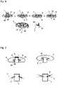
FIG. 1 is a perspective view of a shoe on which a shoelace winding device embodying the present invention is installed, andFIGS 1(a) and 1(b) are cross sectional views of the shoelace winding device, where 1 (a) shows a state in which a dial is in a lock position, and 1(b) shows a state in which the dial is in a release position. -
FIG. 2 is a perspective view of configurational components by disassembling the shoelace winding device embodying the present invention. -
FIG. 3 is a perspective view of a base member and a reel of the shoe ace winding device embodying the present invention. -
FIG. 4 is a perspective view of the dial and a stopper member of the shoelace winding device embodying the present invention. -
FIGS. 5(a) to 5(c) show a shaft member and a spring member of the shoelace winding device embodying the present invention, where 5(a) and 5(b) are perspective views, and 5(c) is a plan view. -
FIG. 6 is a cross sectional diagram showing a manner upon when the shaft member is assembled onto the dial of the shoelace winding device embodying the present invention. -
FIG. 7 is a side diagram showing a positional relationship of the dial and the shaft member, and a manner upon when the spring member rotates of the shoelace winding device embodying the present invention. - The present invention is "a shoelace winding device comprising: a reel for winding a shoelace; a base member including a reel storing section for storing the reel; a dial for rotatively driving the reel, including a stopper member for realizing a lock state in which rotation of the dial can be transmitted to the reel and a release state in which the reel is disconnected from the dial so that the reel can rotate freely; a shaft member to be fixed to the base member to attach the dial to the base member, the shaft member being configured to retain and guide the dial in a state of being movable between a lock position where the dial is caused to approach the base member and a release position where the dial is separated away from the base member; and a spring member having its one end portion axially supported along a direction orthogonally intersecting an axial direction of the shaft member by a bearing section formed at a side portion of the shaft member, and having its other end portion making constant contact with an engaging portion provided on an inner surface of the dial, wherein the shoelace winding device is configured to switch from a lock state of the reel to a release state by the dial moving from the lock position to the release position, an inversion position where the spring member is compressed the most is set at a position between the lock position and the release position, and a direction along which the spring member is compressed is switched between the lock position and the release position", and can suitably be implemented by embodiments and the like to be described below.
- Hereinbelow, an embodiment that implemented the shoelace winding device of the present invention in sports shoes will be described.
-
FIG. 1 shows ashoelace winding device 1 according to the embodiment of the present invention, and a shoe S equipped with theshoelace winding device 1 at a position corresponding to an ankle, and this shoe S is configured such that an instep portion of the shoe S can be tightened by theshoelace 2 configured of a resin-coated metal wire, - The
shoelace winding device 1 is configured of a base member 3, areel 4 for winding theshoelace 2, astopper member 5 for controlling rotation and stop of the reel, adial 6 for rotatively driving thereel 4, ashaft member 7 to be rotatably fixed to the base member 3 for attaching thedial 6 and thestopper member 5 onto the base member 3, aspring member 8 having its one end portion axially supported by theshaft member 7, and the like. - The base member 3 can fix the
shoelace winding device 1 to the shoe S by having a thin plate-shaped U-shaped flange 31 sewn onto the shoe S and fixed thereto, and includes a bottomed cylindrical-shapedreel storing section 32 for rotatably storing thereel 4. - The
reel storing section 32 has arotation shaft 33 for axially supporting thereel 4 projectingly formed at its bottom center, and agear 34 is formed on an inner circumferential surface thereof. - The
gear 34 configures a ratchet mechanism by cooperating withclaws 51 formed on thestopper member 5, and has a cross section formed in a shape of "saw-teeth" so that theclaws 51 can only move in a direction to wind the shoelace 2 (forward rotation). - Further, the base member 3 has shoelace draw-out
openings 35 opened to a bottom of thereel storing section 32 and formed at two portions, and theshoelace 2 wound on thereel 4 can be drawn outside from thereel storing section 32. - The
reel 4 includes ashoelace winding drum 41 for winding theshoelace 2, arotation shaft portion 42 arranged on an inner side of theshoelace winding drum 41, anannular portion 43 connecting an inner circumferential surface of theshoelace winding drum 41 and an outer circumferential surface of therotation shaft portion 42, and anannular groove portion 44 formed by theshoelace winding drum 41, therotation shaft portion 42, and theannular portion 43. - The
rotation shaft 33 of the base member 3 is inserted to an inner surface side of therotation shaft portion 42, and thereel 4 is rotatable within thereel storing section 32, - The
groove portion 44 of thereel 4 is arranged on a side facing the bottom of the base member 3 (hereafter referred to as a "lower side", and an opposite side thereof as an "upper side" for the sake of convenience of explanation), andengagement projections 45 for clamping a distal end of theshoelace 2 to be guided in thegroove portion 44 from an outer circumferential surface side of theshoelace winding drum 41 and retaining the same in thegroove portion 44 are provided within thegroove portion 44. - A plurality of fins 46 is formed along the inner circumferential surface of the shoelace
winding drum 41 on the upper side of thereel 4, and they can transmit the rotation of thedial 6 to the reel by meshing withfins 52 formed on the lower side of thestopper member 5. - The
stopper member 5 is integrated with thedial 6 by engaging with an inner side (lower side) of thedial 6 withattachment claw portions 53 formed at its four corners being engaged withengagement holes 61 formed through thedial 6, and it can realize the lock state in which the rotation of thedial 6 can be transmitted to thereel 4 by being intervened between thereel 4 and thedial 6, and the release state in which thereel 4 is disconnected from thedial 6 so that thereel 4 can freely rotate. - The
shaft member 7 is fixed to the base member 3 by ascrew 9 so as to rotatably attach the integrateddial 6 and stoppermember 5 onto the base member 3, and it can retain and guide the integrateddial 6 and stoppermember 5 in a state of being movable between the lock position in which the integrateddial 6 andstopper member 5 are set close to the base member 3 and the release position in which they are separated from the base member 3. - The
shaft member 7 is formed in a square column shape, and axially supports thespring members 8 in a rotatable manner by one end portion which is linear-shaped (a shaft portion 81) and is formed on thespring members 8 being inserted intobearing sections 71 formed by cutting out two opposing side portions of the shaft member in a direction orthogonally intersecting an axial direction of theshaft member 7. That is, thespring members 8 are arranged one each at positions of theshaft member 7 that are separated about 180 degrees apart. - Further, due to the
shaft member 7 being in the square column shape, the strength of thebearing sections 71 can be increased, which can contribute to making the size of theshaft member 7 compact. - Moreover, the
bearing sections 71 of theshaft member 7 are formed with their inner diameter in the vicinity of their center portions to be the smallest for easy separation from a mold. - Each
spring member 8 has its entirety formed by being curved in a substantially U shape, and acurved spring portion 82 on the other end side makes contact with an engagingportion 62 provided on an inner surface of theintegrated dial 6 andstopper member 5. - The engaging
portion 62 where the other end portion (spring portion 82) of thespring member 8 makes contact is provided at an outer end narrowest portion of aspring storing space 63 formed in a cuneate shape at a boundary portion between thedial 6 and thestopper member 5. - Further, the
reel 4 can be switched from a lock state to a release state by theintegrated dial 6 andstopper member 5 being moved from the lock position to the release position. - Moreover, an inversion position L where the
spring portions 82 of thespring members 8 are most compressed toward the shaft member side is set to be present at a position between the lock position and the release position. - A disk-shaped
cap 10 is engaged with an upper side of thedial 6 so that dust and the like do not enter the inside of theshoelace winding device 1. - Meanwhile, a through
hole 11 is formed at a center portion of thecap 10, and thereel 4, thedial 6, and theshaft member 7 can be disassembled from the base member 3 by operating thescrew 9 within the inner side (lower side) of thecap 10 through this throughhole 11. - As the wire-shaped
shoelace 2 formed of a composite material of resin and metal, a wire rope in which 49 strings of stainless wires with a diameter of 0.11 to 0.13 mm are twisted that is processed by a swaging machine and coated by nylon resin can suitably be used. - Next, a method of manufacturing the
shoelace winding device 1 described above by assembling the respective components will be described. - Firstly, in order to attach the
reel 4 to the base member 3 of theshoelace winding device 1, tip ends of theshoelace 2 are inserted to the shoelace draw-outopenings 35 provided at two positions, and the both ends of theshoelace 2 are drawn out from thereel storing section 32 side. - Then, the both ends of the
shoelace 2 are fixed to thereel 4 by sequentially inserting the tip ends of theshoelace 2 into wire insertion holes provided at six positions on thereel 4 in a sewing manner, and thereel 4 is arranged inside thereel storing section 32. - Next, the
stopper member 5 and thedial 6 are integrated by engaging thestopper member 5 to the inner side (lower side) of thedial 6, and theshaft member 7 and thespring members 8 are assembled thereto. - In this case, the
shaft member 7 is inserted into a substantially square-shapedaxial hole 64 formed in thedial 6 and a substantially square-shapedaxial hole 54 formed in thestopper member 5, whereas thespring portions 82 of thespring members 8 are inserted intospring storing spaces 63 from expanded portions where theaxial hole 64 of thedial 6 is expanded, and moreover eachspring portion 82 is guided to rotatingly move to the outer end narrowest portion side from the inner end side of thespring storing space 63, and is assembled to thedial 6. - Meanwhile, a
flange 72 formed at an upper end portion of theshaft member 7 makes contact with an engagingstep portion 65 formed at an edge of theaxial hole 64 of thedial 6, whereby thedial 6 does not come off from theshaft member 7. - The
spring portions 82 of thespring members 8 being guided to rotatingly move from the inner end side of thespring storing spaces 63 toward the outer end narrowest portion side is realized because anangled surface 55 facing an upper side (dial side) is formed at an edge of theaxial hole 54 of thestopper member 5. - After having assembled the
stopper member 5, thedial 6, theshaft member 7, and thespring members 8 by the above procedures, thescrew 9 is inserted into ascrew insertion hole 73 penetratingly formed along an axis of theshaft member 7, and theshaft member 7 and the other parts are attached to the base member 3. - The
shoelace winding device 1 can be assembled by fitting thecap 10 onto thedial 6 at last. - In disassembling the
shoelace winding device 1 for maintenance or repair, a screwdriver is inserted from the throughhole 11 of thecap 10 and thescrew 9 is taken off, whereby thestopper member 5, thedial 6, theshaft member 7, and thespring members 8 that were assembled can be taken off from the base member 3. - As cases where the maintenance or repair is necessary, a case where the
shoelace 2 has been torn and a case where theshoelace 2 is entangled within thereel storing section 32 are most likely to happen, so being able to disconnect thestopper member 5, thedial 6, theshaft member 7, and thespring members 8 while they are being assembled from the base member 3 is very effective in improving the efficiency of the maintenance or repair work. - Meanwhile, as materials configuring the respective components in the
shoelace winding device 1 of the present embodiment, the followings were used as an example in consideration of their strength, durability, elasticity and the like; however, materials are not limited thereto.
Base member 3: Nylon
Reel 4,stopper member 5, and shaft member 7: POM (polyacetal)
Dial 6: Nylon and TPE (thermoplastic elastomer) at a periphery thereof
Spring members 8: Stainless steel
Screw 9: Carbon steel
Cap 10: ABS resin - A method of use of the
shoelace winding device 1 configured as above will be described. - In order to tighten the
shoelace 2 after the shoe S is put on, thedial 6 of theshoelace winding device 1 is operated to rotate at the lock position where thedial 6 is caused to approach the base member 3, and theshoelace 2 is wound on thereel 4 thereby. - In this case, the
reel 4 does not rotate in a direction with which theshoelace 2 is loosened by theclaws 51 of thestopper member 5 making contact with thegear 34. - Further, since the inversion position L where the
spring members 8 are compressed the most is set at the position between the lock position and the release position, thespring members 8 are in the state shown in left side ofFIG. 7 when thedial 6 is in the lock position, wherein thedial 6 is retained in the lock position. - At this occasion, the
spring members 8 are oriented in a direction along which theshaft member 7 is lifted and thedial 6 is pressed down. - Next, in order to loosen the tightened
shoelace 2, thedial 6 of theshoelace winding device 1 is pulled to the upper side. - At this occasion, the
spring members 8 are compressed, and by further pulling thedial 6 to the upper side against the repelling force thereof, thespring members 8 go beyond the inversion position L where they are compressed the most, the direction toward which thespring members 8 are compressed switches between the lock position and the release position, whereby thedial 6 is moved to the release position separated away from the base member 3 (state shown in right side ofFIG. 7 ). - At this occasion, the
spring members 8 are oriented in a direction along which theshaft member 7 is pressed down and thedial 6 is lifted. - The other end portions (spring portions 82) of the
spring members 8 are making constant contact with the engagingportions 62 provided on the inner surface of thedial 6, whereby the wear of the components can be prevented. - Meanwhile, "making constant contact" is employed to improve the reliability, durability, and operability of the
shoelace winding device 1 and omit fluctuation of thedial 6, and it does not intend to exclude the presence of some "play", so long as it does not affect the operation of theshoelace winding device 1. - Since the
spring members 8 switch clearly between the lock position and the release position, not only the operability is improved, but also it is easy to understand the state of the position where thedial 6 resides. - As above, when the
dial 6 moves from the lock position to the release position, engagement between the fins 46 of thereel 4 and thefins 52 of thestopper member 5 is released, whereby thereel 4 becomes freely rotatable, and theshoelace 2 is loosened thereby. - By contrast, if the
dial 6 is pressed down so as to move from the release position to the lock position, thespring members 8 go, in the opposite direction, beyond the inversion position L where they are compressed the most, and the fins 46 of thereel 4 and thefins 52 of thestopper member 5 again engage with one another; thus theshoelace 2 can be tightened by winding theshoelace 2 onto thereel 4. - Meanwhile, in the description, a shape of the "dial" is not specifically limited so long as it functions as an operating section for rotatively driving the
reef 4, and it may have a polygonal shape. - The present invention is not limited to the
shoelace winding device 1 for tightening theshoelace 2 arranged as in the configuration shown in the drawings, and may be embodied in a shoelace winding device for tightening ashoelace 2 which tightens a different portion of the shoe S. - Furthermore, implementations can be made while suitably making changes to materials, shapes, dimensions, angles, arranged positions, sizes, numbers and the like of the respective parts of the shoelace winding device.
- The present invention is small-sized and light weight, has superior durability, operability, and maintenance, and can suitably be used as a shoelace winding device that can conveniently be used in various types of shoes.
-
- 1 Shoelace Winding Device
- 2 Shoelace
- 3 Base Member
- 31 Flange
- 32 Reel Storing Section
- 33 Rotation Shaft
- 34 Gear
- 35 Shoelace Draw-out Opening
- 4 Reel
- 41 Shoelace Winding Drum
- 42 Rotation Shaft Portion
- 43 Annular Portion
- 44 Groove Portion
- 45 Engagement Projection
- 46 Fin
- 5 Stopper Member
- 51 Claw
- 52 Fin
- 53 Attachment Claw Portion
- 54 Axial Hole
- 55 Angled Surface
- 6 Dial
- 61 Engagement Hole
- 62 Engaging Portion
- 63 Spring Storing Space
- 64 Axial Hole
- 65 Engaging Step Portion
- 7 Shaft Member
- 71 Bearing Section
- 72 Flange
- 73 Screw Insertion Hole
- 8 Spring Member
- 81 Shaft Portion (one end portion)
- 82 Spring Portion (the other end portion)
- 9 Screw
- 10 Cap
- 11 Through Hole
- S Shoe
- L Inversion Position
Claims (5)
- A shoelace winding device (1) comprising:a reel (4) for winding a shoelace (2);a base member (3) including a reel storing section (32) for storing the reel (4);a dial (6) for rotatively driving the reel (4), including a stopper member (5) for realizing a lock state in which rotation of the dial (6) can be transmitted to the reel (4) and a release state in which the reel (4) is disconnected from the dial (6) so that the reel (4) can rotate freely;a shaft member (7) to be fixed to the base member (3) to attach the dial (6) to the base member (3), the shaft member (7) being configured to retain and guide the dial (6) in a state of being movable between a lock position where the dial (6) is caused to approach the base member (3) and a release position where the dial is separated away from the base member (3); anda spring member (8),wherein the shoelace winding device (1) is configured to switch from a lock state of the reel (4) to a release state by the dial (6) moving from the lock position to the release position, an inversion position where the spring member (8) is compressed the most is set at a position between the lock position and the release position, characterized in thatthe spring member (8) has its one end portion (81) axially supported along a direction orthogonally intersecting an axial direction of the shaft member (7) by a bearing section (71) formed at a side portion of the shaft member (7), and has its other end portion (82) making constant contact with an engaging portion (62) provided on an inner surface of the dial (6), and in that the direction along which the spring member (8) is compressed is switched between the lock position and the release position.
- The shoelace winding device (1) according to claim 1, wherein:the stopper member (5) is fitted inside the dial (6) and integrated with the dial (6); andthe engaging portion (62) where the other end portion (82) of the spring member (8) makes contact is provided at an outer end narrowest portion of a spring storing space (63) formed in a cuneate shape at a boundary portion between the dial (6) and the stopper member (5).
- The shoelace winding device (1) according to claim 2, wherein
the spring member (8) is assembled to the dial (6) by the other end portion (82) of the spring member (8) being inserted into the spring storing space (63) from an expanded portion where an axial hole (64) of the dial (6) is expanded, and further the other end portion (82) being guided to be moved around from an inner end side of the spring storing space (63) toward an outer end narrowest portion side when the spring member (8) is inserted into axial holes (54, 64) formed on the dial (6) and the stopper member (5). - The shoelace winding device (1) according to claim 1, wherein:the spring member (8) is a spring member that is curvedly formed in a substantially U-shape;a linear-shaped shaft portion of the spring member (8) on one end side is axially supported along the direction orthogonally intersecting the axial direction of the shaft member (7) by the bearing section (71) formed at the side portion of the shaft member (7); anda curved spring portion (82) on the other end side makes contact with the engaging portion(62).
- The shoelace winding device (1) according to claim 1, wherein
one spring member (8) is arranged at each of positions on the shaft member (7) that are separated about 180 degrees apart.
Applications Claiming Priority (2)
| Application Number | Priority Date | Filing Date | Title |
|---|---|---|---|
| JP2013127574A JP6087219B2 (en) | 2013-06-18 | 2013-06-18 | Shoelace winding device |
| PCT/JP2013/078116 WO2014203415A1 (en) | 2013-06-18 | 2013-10-17 | Shoelace winding device |
Publications (3)
| Publication Number | Publication Date |
|---|---|
| EP3011856A1 EP3011856A1 (en) | 2016-04-27 |
| EP3011856A4 EP3011856A4 (en) | 2017-02-15 |
| EP3011856B1 true EP3011856B1 (en) | 2019-06-12 |
Family
ID=52104174
Family Applications (1)
| Application Number | Title | Priority Date | Filing Date |
|---|---|---|---|
| EP13886148.9A Active EP3011856B1 (en) | 2013-06-18 | 2013-10-17 | Shoelace winding device |
Country Status (10)
| Country | Link |
|---|---|
| US (1) | US9635906B2 (en) |
| EP (1) | EP3011856B1 (en) |
| JP (1) | JP6087219B2 (en) |
| KR (1) | KR101705017B1 (en) |
| CN (1) | CN104540411B (en) |
| AU (1) | AU2013391431B2 (en) |
| CA (1) | CA2876000C (en) |
| HK (1) | HK1203782A1 (en) |
| TW (1) | TWI625103B (en) |
| WO (1) | WO2014203415A1 (en) |
Families Citing this family (26)
| Publication number | Priority date | Publication date | Assignee | Title |
|---|---|---|---|---|
| CN104003064B (en) * | 2013-02-26 | 2016-06-29 | 国基电子(上海)有限公司 | Wire harness apparatus |
| ITTV20130045A1 (en) * | 2013-04-09 | 2014-10-10 | Northwave Srl | TIGHTENING DEVICE |
| JP6406919B2 (en) | 2014-08-11 | 2018-10-17 | 株式会社ジャパーナ | Shoelace winding device mounting structure |
| JP6450584B2 (en) * | 2014-12-22 | 2019-01-09 | 株式会社ジャパーナ | Winding device and shoes equipped therewith |
| US10264852B2 (en) | 2015-01-14 | 2019-04-23 | Sug Whan Kim | String winding and unwinding apparatus |
| KR101569461B1 (en) * | 2015-01-14 | 2015-11-18 | 스피어다인 주식회사 | String winding and unwinding apparatus |
| JP6687307B2 (en) * | 2015-10-23 | 2020-04-22 | 株式会社ジャパーナ | Winding device |
| CN106919220B (en) * | 2015-12-25 | 2018-06-05 | 陈金柱 | Clamp device |
| US9861164B2 (en) * | 2016-03-15 | 2018-01-09 | Nike, Inc. | Tensioning system and reel member for an article of footwear |
| JP2017169773A (en) * | 2016-03-23 | 2017-09-28 | 株式会社ジャパーナ | Shoe |
| JP6810530B2 (en) * | 2016-04-04 | 2021-01-06 | 株式会社アルペン | Winding device |
| CN106428993B (en) * | 2016-07-29 | 2019-03-08 | 温州职业技术学院 | A kind of enlacement packaging device |
| JP6882827B2 (en) * | 2016-08-10 | 2021-06-02 | 株式会社アルペン | Winding device |
| US10588381B2 (en) | 2016-11-21 | 2020-03-17 | Under Armour, Inc. | Footwear with internal harness |
| CN106723663B (en) * | 2017-01-24 | 2019-05-24 | 深圳市悠宁科技有限公司 | Shoestring draw off gear |
| JP6881993B2 (en) | 2017-02-01 | 2021-06-02 | 株式会社アルペン | Articles equipped with a string take-up device |
| JP2018121920A (en) * | 2017-02-01 | 2018-08-09 | 株式会社ジャパーナ | Take-up device |
| DE102018201019A1 (en) | 2017-02-28 | 2018-08-30 | Fidlock Gmbh | Closure device with a winding element |
| DE102018201021A1 (en) | 2017-11-14 | 2019-05-16 | Fidlock Gmbh | Closure device with a winding element |
| KR102026210B1 (en) * | 2019-04-23 | 2019-09-27 | 한양대학교 산학협력단 | Artficial arm using jog dial |
| US20220234862A1 (en) | 2019-06-05 | 2022-07-28 | Garrett Ray Hurley | Tool operated adjustment devices, fit systems, and line tensioning systems |
| DE102019217036A1 (en) * | 2019-11-05 | 2021-05-06 | Fidlock Gmbh | Closure device with a rotating element |
| EP4144250A4 (en) * | 2021-07-19 | 2023-03-08 | Shishi Senke Intelligent Technology Co., Ltd. | Rotary push-pull rope winder and shoes |
| TWM623553U (en) * | 2021-08-18 | 2022-02-21 | 陳金柱 | Fastening device |
| JP7126286B1 (en) | 2021-11-18 | 2022-08-26 | 有限会社Vital-Fuss-Kochi | Lace-up shoes and tightening method for lace-up shoes |
| CN117794426A (en) * | 2022-07-19 | 2024-03-29 | kerata株式会社 | Baby harness |
Family Cites Families (40)
| Publication number | Priority date | Publication date | Assignee | Title |
|---|---|---|---|---|
| JPS583428Y2 (en) | 1978-01-17 | 1983-01-20 | 東成産業株式会社 | Hanger rope for drying clothes |
| IT1193578B (en) | 1981-01-28 | 1988-07-08 | Nordica Spa | CLOSING DEVICE PARTICULARLY FOR SKI BOOTS |
| IT1184540B (en) * | 1985-05-06 | 1987-10-28 | Nordica Spa | SKI BOOT WITH LEG CLOSURE DEVICE |
| DE3926514A1 (en) | 1989-08-10 | 1991-02-14 | Weinmann & Co Kg | TURN LOCK FOR A SPORTSHOE, ESPECIALLY A SKI SHOE |
| US5157813A (en) | 1991-10-31 | 1992-10-27 | William Carroll | Shoelace tensioning device |
| DE9200982U1 (en) | 1992-01-28 | 1993-05-27 | Puma Ag Rudolf Dassler Sport, 8522 Herzogenaurach, De | |
| DE4240916C1 (en) | 1992-12-04 | 1993-10-07 | Jungkind Roland | Shoe closure |
| EP0651954B1 (en) | 1993-11-04 | 1999-02-10 | Am S.R.L. | Fastening device for sport shoe |
| US5934599A (en) | 1997-08-22 | 1999-08-10 | Hammerslag; Gary R. | Footwear lacing system |
| US6289558B1 (en) | 1997-08-22 | 2001-09-18 | Boa Technology, Inc. | Footwear lacing system |
| US20060156517A1 (en) * | 1997-08-22 | 2006-07-20 | Hammerslag Gary R | Reel based closure system |
| WO2002024543A1 (en) | 2000-09-19 | 2002-03-28 | Freed Anna B | Closure |
| TW569680U (en) * | 2003-03-07 | 2004-01-01 | Morning Internat Co Ltd | Bootlace tighten structure summary of the invention |
| DE10335940A1 (en) | 2003-08-04 | 2005-03-10 | Japana Co | Tensioning device for pull cables, in particular pull cable laces on shoes |
| US7516914B2 (en) | 2004-05-07 | 2009-04-14 | Enventys, Llc | Bi-directional device |
| US20110167543A1 (en) | 2004-05-07 | 2011-07-14 | Enventys, Llc | Adjustable protective apparel |
| EP1814417B1 (en) | 2004-10-29 | 2014-04-16 | Boa Technology, Inc. | Reel based closure system |
| KR100598627B1 (en) | 2005-06-27 | 2006-07-13 | 주식회사 신경 | The device for tightenning up a shoelace |
| DE102005037967A1 (en) | 2005-08-11 | 2007-02-15 | Head Germany Gmbh | Screw cap for a shoe |
| WO2007081822A2 (en) | 2006-01-06 | 2007-07-19 | Boa Technology, Inc. | Rough and fine adjustment closure system |
| CN201015448Y (en) * | 2007-02-02 | 2008-02-06 | 盟汉塑胶股份有限公司 | Shoes coil winder |
| CN201029494Y (en) * | 2007-03-29 | 2008-03-05 | 董兵秋 | Improved shoestring fastener |
| KR20100129278A (en) | 2008-01-18 | 2010-12-08 | 보아 테크놀러지, 인크. | Closure system |
| WO2010059989A2 (en) | 2008-11-21 | 2010-05-27 | Boa Technology, Inc. | Reel based lacing system |
| US8245371B2 (en) * | 2009-04-01 | 2012-08-21 | Chin Chu Chen | String securing device |
| TW201127310A (en) * | 2010-02-11 | 2011-08-16 | jin-zhu Chen | Step-less finetuning buckle |
| US8707486B2 (en) * | 2010-02-16 | 2014-04-29 | Allen Medical Systems, Inc. | Lacing system to secure a limb in a surgical support apparatus |
| US9375053B2 (en) * | 2012-03-15 | 2016-06-28 | Boa Technology, Inc. | Tightening mechanisms and applications including the same |
| JP5925765B2 (en) | 2010-04-30 | 2016-05-25 | ボア テクノロジー,インコーポレイテッド | Reel for use in a lacing system, method of making the reel, and pawl used with the reel |
| CA2804759C (en) | 2010-07-01 | 2019-06-18 | Boa Technology, Inc. | Braces using lacing systems |
| JP5727771B2 (en) | 2010-12-08 | 2015-06-03 | 株式会社ジャパーナ | Shoelace winding device |
| US8353087B2 (en) * | 2011-03-07 | 2013-01-15 | Chin-Chu Chen | Closure device |
| KR101107372B1 (en) | 2011-05-30 | 2012-01-19 | 소윤서 | Apparatus for adjusting length of lace |
| KR101099458B1 (en) | 2011-07-25 | 2011-12-27 | 주식회사 신경 | Apparatus for fastening shoe strip |
| US9101181B2 (en) * | 2011-10-13 | 2015-08-11 | Boa Technology Inc. | Reel-based lacing system |
| HUE033756T2 (en) * | 2012-11-30 | 2017-12-28 | Puma SE | Rotary closure for a shoe |
| EP2948014B1 (en) * | 2013-01-28 | 2019-06-26 | Boa Technology Inc. | Lace fixation assembly and system |
| KR101506676B1 (en) | 2013-09-03 | 2015-03-30 | 주식회사 신경 | apparatus for fastening wire and method for mounting thereof |
| TWI561453B (en) | 2014-02-17 | 2016-12-11 | Chin Chu Chen | A device for tightening and loosening a lace |
| US9364054B2 (en) * | 2014-04-09 | 2016-06-14 | Tristan S. Gittens | Accessory cinching device |
-
2013
- 2013-06-18 JP JP2013127574A patent/JP6087219B2/en active Active
- 2013-10-17 KR KR1020147021604A patent/KR101705017B1/en active IP Right Grant
- 2013-10-17 CN CN201380027506.5A patent/CN104540411B/en active Active
- 2013-10-17 WO PCT/JP2013/078116 patent/WO2014203415A1/en active Application Filing
- 2013-10-17 US US14/405,733 patent/US9635906B2/en active Active
- 2013-10-17 EP EP13886148.9A patent/EP3011856B1/en active Active
- 2013-10-17 AU AU2013391431A patent/AU2013391431B2/en not_active Ceased
- 2013-10-17 CA CA2876000A patent/CA2876000C/en not_active Expired - Fee Related
-
2014
- 2014-06-04 TW TW103119313A patent/TWI625103B/en not_active IP Right Cessation
-
2015
- 2015-05-08 HK HK15104394.7A patent/HK1203782A1/en unknown
Non-Patent Citations (1)
| Title |
|---|
| None * |
Also Published As
| Publication number | Publication date |
|---|---|
| WO2014203415A1 (en) | 2014-12-24 |
| EP3011856A1 (en) | 2016-04-27 |
| HK1203782A1 (en) | 2015-11-06 |
| AU2013391431B2 (en) | 2017-02-02 |
| EP3011856A4 (en) | 2017-02-15 |
| AU2013391431A1 (en) | 2015-01-22 |
| CA2876000C (en) | 2017-01-17 |
| TW201509325A (en) | 2015-03-16 |
| KR101705017B1 (en) | 2017-02-09 |
| US20160262496A1 (en) | 2016-09-15 |
| CA2876000A1 (en) | 2014-12-24 |
| CN104540411A (en) | 2015-04-22 |
| KR20150032515A (en) | 2015-03-26 |
| US9635906B2 (en) | 2017-05-02 |
| JP6087219B2 (en) | 2017-03-01 |
| JP2015000293A (en) | 2015-01-05 |
| CN104540411B (en) | 2016-04-20 |
| TWI625103B (en) | 2018-06-01 |
Similar Documents
| Publication | Publication Date | Title |
|---|---|---|
| EP3011856B1 (en) | Shoelace winding device | |
| CA2876003C (en) | Shoelace winding reel | |
| JP6882827B2 (en) | Winding device | |
| CN103153112B (en) | Reel based lacing system | |
| EP3875415A1 (en) | Fastening device | |
| US20210282503A1 (en) | Fastening device | |
| EP2508094B1 (en) | Loop for shoelace utilizing asymmetric pulley | |
| US20200337418A1 (en) | Fastening device | |
| JP2016116756A (en) | Winder and shoe equipped with the same | |
| WO2018143060A1 (en) | Winding device | |
| WO2017068937A1 (en) | Winding device |
Legal Events
| Date | Code | Title | Description |
|---|---|---|---|
| PUAI | Public reference made under article 153(3) epc to a published international application that has entered the european phase |
Free format text: ORIGINAL CODE: 0009012 |
|
| 17P | Request for examination filed |
Effective date: 20141204 |
|
| AK | Designated contracting states |
Kind code of ref document: A1 Designated state(s): AL AT BE BG CH CY CZ DE DK EE ES FI FR GB GR HR HU IE IS IT LI LT LU LV MC MK MT NL NO PL PT RO RS SE SI SK SM TR |
|
| AX | Request for extension of the european patent |
Extension state: BA ME |
|
| DAX | Request for extension of the european patent (deleted) | ||
| A4 | Supplementary search report drawn up and despatched |
Effective date: 20170116 |
|
| RIC1 | Information provided on ipc code assigned before grant |
Ipc: A43C 11/16 20060101AFI20170110BHEP Ipc: A43B 11/00 20060101ALI20170110BHEP Ipc: A43B 23/02 20060101ALI20170110BHEP Ipc: A43C 7/00 20060101ALI20170110BHEP |
|
| GRAP | Despatch of communication of intention to grant a patent |
Free format text: ORIGINAL CODE: EPIDOSNIGR1 |
|
| STAA | Information on the status of an ep patent application or granted ep patent |
Free format text: STATUS: GRANT OF PATENT IS INTENDED |
|
| INTG | Intention to grant announced |
Effective date: 20190107 |
|
| GRAS | Grant fee paid |
Free format text: ORIGINAL CODE: EPIDOSNIGR3 |
|
| GRAA | (expected) grant |
Free format text: ORIGINAL CODE: 0009210 |
|
| STAA | Information on the status of an ep patent application or granted ep patent |
Free format text: STATUS: THE PATENT HAS BEEN GRANTED |
|
| AK | Designated contracting states |
Kind code of ref document: B1 Designated state(s): AL AT BE BG CH CY CZ DE DK EE ES FI FR GB GR HR HU IE IS IT LI LT LU LV MC MK MT NL NO PL PT RO RS SE SI SK SM TR |
|
| REG | Reference to a national code |
Ref country code: GB Ref legal event code: FG4D |
|
| REG | Reference to a national code |
Ref country code: CH Ref legal event code: EP |
|
| REG | Reference to a national code |
Ref country code: AT Ref legal event code: REF Ref document number: 1141416 Country of ref document: AT Kind code of ref document: T Effective date: 20190615 |
|
| REG | Reference to a national code |
Ref country code: DE Ref legal event code: R096 Ref document number: 602013056669 Country of ref document: DE |
|
| REG | Reference to a national code |
Ref country code: IE Ref legal event code: FG4D |
|
| REG | Reference to a national code |
Ref country code: NL Ref legal event code: MP Effective date: 20190612 |
|
| REG | Reference to a national code |
Ref country code: LT Ref legal event code: MG4D |
|
| PG25 | Lapsed in a contracting state [announced via postgrant information from national office to epo] |
Ref country code: SE Free format text: LAPSE BECAUSE OF FAILURE TO SUBMIT A TRANSLATION OF THE DESCRIPTION OR TO PAY THE FEE WITHIN THE PRESCRIBED TIME-LIMIT Effective date: 20190612 Ref country code: HR Free format text: LAPSE BECAUSE OF FAILURE TO SUBMIT A TRANSLATION OF THE DESCRIPTION OR TO PAY THE FEE WITHIN THE PRESCRIBED TIME-LIMIT Effective date: 20190612 Ref country code: AL Free format text: LAPSE BECAUSE OF FAILURE TO SUBMIT A TRANSLATION OF THE DESCRIPTION OR TO PAY THE FEE WITHIN THE PRESCRIBED TIME-LIMIT Effective date: 20190612 Ref country code: FI Free format text: LAPSE BECAUSE OF FAILURE TO SUBMIT A TRANSLATION OF THE DESCRIPTION OR TO PAY THE FEE WITHIN THE PRESCRIBED TIME-LIMIT Effective date: 20190612 Ref country code: NO Free format text: LAPSE BECAUSE OF FAILURE TO SUBMIT A TRANSLATION OF THE DESCRIPTION OR TO PAY THE FEE WITHIN THE PRESCRIBED TIME-LIMIT Effective date: 20190912 Ref country code: LT Free format text: LAPSE BECAUSE OF FAILURE TO SUBMIT A TRANSLATION OF THE DESCRIPTION OR TO PAY THE FEE WITHIN THE PRESCRIBED TIME-LIMIT Effective date: 20190612 |
|
| PG25 | Lapsed in a contracting state [announced via postgrant information from national office to epo] |
Ref country code: GR Free format text: LAPSE BECAUSE OF FAILURE TO SUBMIT A TRANSLATION OF THE DESCRIPTION OR TO PAY THE FEE WITHIN THE PRESCRIBED TIME-LIMIT Effective date: 20190913 Ref country code: BG Free format text: LAPSE BECAUSE OF FAILURE TO SUBMIT A TRANSLATION OF THE DESCRIPTION OR TO PAY THE FEE WITHIN THE PRESCRIBED TIME-LIMIT Effective date: 20190912 Ref country code: RS Free format text: LAPSE BECAUSE OF FAILURE TO SUBMIT A TRANSLATION OF THE DESCRIPTION OR TO PAY THE FEE WITHIN THE PRESCRIBED TIME-LIMIT Effective date: 20190612 Ref country code: LV Free format text: LAPSE BECAUSE OF FAILURE TO SUBMIT A TRANSLATION OF THE DESCRIPTION OR TO PAY THE FEE WITHIN THE PRESCRIBED TIME-LIMIT Effective date: 20190612 |
|
| REG | Reference to a national code |
Ref country code: AT Ref legal event code: MK05 Ref document number: 1141416 Country of ref document: AT Kind code of ref document: T Effective date: 20190612 |
|
| PG25 | Lapsed in a contracting state [announced via postgrant information from national office to epo] |
Ref country code: NL Free format text: LAPSE BECAUSE OF FAILURE TO SUBMIT A TRANSLATION OF THE DESCRIPTION OR TO PAY THE FEE WITHIN THE PRESCRIBED TIME-LIMIT Effective date: 20190612 Ref country code: EE Free format text: LAPSE BECAUSE OF FAILURE TO SUBMIT A TRANSLATION OF THE DESCRIPTION OR TO PAY THE FEE WITHIN THE PRESCRIBED TIME-LIMIT Effective date: 20190612 Ref country code: AT Free format text: LAPSE BECAUSE OF FAILURE TO SUBMIT A TRANSLATION OF THE DESCRIPTION OR TO PAY THE FEE WITHIN THE PRESCRIBED TIME-LIMIT Effective date: 20190612 Ref country code: RO Free format text: LAPSE BECAUSE OF FAILURE TO SUBMIT A TRANSLATION OF THE DESCRIPTION OR TO PAY THE FEE WITHIN THE PRESCRIBED TIME-LIMIT Effective date: 20190612 Ref country code: CZ Free format text: LAPSE BECAUSE OF FAILURE TO SUBMIT A TRANSLATION OF THE DESCRIPTION OR TO PAY THE FEE WITHIN THE PRESCRIBED TIME-LIMIT Effective date: 20190612 Ref country code: SK Free format text: LAPSE BECAUSE OF FAILURE TO SUBMIT A TRANSLATION OF THE DESCRIPTION OR TO PAY THE FEE WITHIN THE PRESCRIBED TIME-LIMIT Effective date: 20190612 Ref country code: PT Free format text: LAPSE BECAUSE OF FAILURE TO SUBMIT A TRANSLATION OF THE DESCRIPTION OR TO PAY THE FEE WITHIN THE PRESCRIBED TIME-LIMIT Effective date: 20191014 |
|
| PG25 | Lapsed in a contracting state [announced via postgrant information from national office to epo] |
Ref country code: IS Free format text: LAPSE BECAUSE OF FAILURE TO SUBMIT A TRANSLATION OF THE DESCRIPTION OR TO PAY THE FEE WITHIN THE PRESCRIBED TIME-LIMIT Effective date: 20191012 Ref country code: SM Free format text: LAPSE BECAUSE OF FAILURE TO SUBMIT A TRANSLATION OF THE DESCRIPTION OR TO PAY THE FEE WITHIN THE PRESCRIBED TIME-LIMIT Effective date: 20190612 Ref country code: IT Free format text: LAPSE BECAUSE OF FAILURE TO SUBMIT A TRANSLATION OF THE DESCRIPTION OR TO PAY THE FEE WITHIN THE PRESCRIBED TIME-LIMIT Effective date: 20190612 Ref country code: ES Free format text: LAPSE BECAUSE OF FAILURE TO SUBMIT A TRANSLATION OF THE DESCRIPTION OR TO PAY THE FEE WITHIN THE PRESCRIBED TIME-LIMIT Effective date: 20190612 |
|
| REG | Reference to a national code |
Ref country code: DE Ref legal event code: R097 Ref document number: 602013056669 Country of ref document: DE |
|
| PG25 | Lapsed in a contracting state [announced via postgrant information from national office to epo] |
Ref country code: TR Free format text: LAPSE BECAUSE OF FAILURE TO SUBMIT A TRANSLATION OF THE DESCRIPTION OR TO PAY THE FEE WITHIN THE PRESCRIBED TIME-LIMIT Effective date: 20190612 |
|
| PLBE | No opposition filed within time limit |
Free format text: ORIGINAL CODE: 0009261 |
|
| STAA | Information on the status of an ep patent application or granted ep patent |
Free format text: STATUS: NO OPPOSITION FILED WITHIN TIME LIMIT |
|
| PG25 | Lapsed in a contracting state [announced via postgrant information from national office to epo] |
Ref country code: DK Free format text: LAPSE BECAUSE OF FAILURE TO SUBMIT A TRANSLATION OF THE DESCRIPTION OR TO PAY THE FEE WITHIN THE PRESCRIBED TIME-LIMIT Effective date: 20190612 Ref country code: PL Free format text: LAPSE BECAUSE OF FAILURE TO SUBMIT A TRANSLATION OF THE DESCRIPTION OR TO PAY THE FEE WITHIN THE PRESCRIBED TIME-LIMIT Effective date: 20190612 |
|
| 26N | No opposition filed |
Effective date: 20200313 |
|
| PG25 | Lapsed in a contracting state [announced via postgrant information from national office to epo] |
Ref country code: IS Free format text: LAPSE BECAUSE OF FAILURE TO SUBMIT A TRANSLATION OF THE DESCRIPTION OR TO PAY THE FEE WITHIN THE PRESCRIBED TIME-LIMIT Effective date: 20200224 Ref country code: SI Free format text: LAPSE BECAUSE OF FAILURE TO SUBMIT A TRANSLATION OF THE DESCRIPTION OR TO PAY THE FEE WITHIN THE PRESCRIBED TIME-LIMIT Effective date: 20190612 Ref country code: MC Free format text: LAPSE BECAUSE OF FAILURE TO SUBMIT A TRANSLATION OF THE DESCRIPTION OR TO PAY THE FEE WITHIN THE PRESCRIBED TIME-LIMIT Effective date: 20190612 |
|
| REG | Reference to a national code |
Ref country code: CH Ref legal event code: PL |
|
| PG2D | Information on lapse in contracting state deleted |
Ref country code: IS |
|
| PG25 | Lapsed in a contracting state [announced via postgrant information from national office to epo] |
Ref country code: LI Free format text: LAPSE BECAUSE OF NON-PAYMENT OF DUE FEES Effective date: 20191031 Ref country code: CH Free format text: LAPSE BECAUSE OF NON-PAYMENT OF DUE FEES Effective date: 20191031 Ref country code: LU Free format text: LAPSE BECAUSE OF NON-PAYMENT OF DUE FEES Effective date: 20191017 |
|
| REG | Reference to a national code |
Ref country code: BE Ref legal event code: MM Effective date: 20191031 |
|
| PG25 | Lapsed in a contracting state [announced via postgrant information from national office to epo] |
Ref country code: BE Free format text: LAPSE BECAUSE OF NON-PAYMENT OF DUE FEES Effective date: 20191031 |
|
| GBPC | Gb: european patent ceased through non-payment of renewal fee |
Effective date: 20191017 |
|
| PG25 | Lapsed in a contracting state [announced via postgrant information from national office to epo] |
Ref country code: GB Free format text: LAPSE BECAUSE OF NON-PAYMENT OF DUE FEES Effective date: 20191017 Ref country code: FR Free format text: LAPSE BECAUSE OF NON-PAYMENT OF DUE FEES Effective date: 20191031 Ref country code: IE Free format text: LAPSE BECAUSE OF NON-PAYMENT OF DUE FEES Effective date: 20191017 |
|
| REG | Reference to a national code |
Ref country code: DE Ref legal event code: R082 Ref document number: 602013056669 Country of ref document: DE Representative=s name: EISENFUEHR SPEISER PATENTANWAELTE RECHTSANWAEL, DE Ref country code: DE Ref legal event code: R081 Ref document number: 602013056669 Country of ref document: DE Owner name: ALPEN CO., LTD., JP Free format text: FORMER OWNER: JAPANA CO., LTD., NAGOYA-CITY, AICHI, JP |
|
| PG25 | Lapsed in a contracting state [announced via postgrant information from national office to epo] |
Ref country code: CY Free format text: LAPSE BECAUSE OF FAILURE TO SUBMIT A TRANSLATION OF THE DESCRIPTION OR TO PAY THE FEE WITHIN THE PRESCRIBED TIME-LIMIT Effective date: 20190612 |
|
| PG25 | Lapsed in a contracting state [announced via postgrant information from national office to epo] |
Ref country code: MT Free format text: LAPSE BECAUSE OF FAILURE TO SUBMIT A TRANSLATION OF THE DESCRIPTION OR TO PAY THE FEE WITHIN THE PRESCRIBED TIME-LIMIT Effective date: 20190612 Ref country code: HU Free format text: LAPSE BECAUSE OF FAILURE TO SUBMIT A TRANSLATION OF THE DESCRIPTION OR TO PAY THE FEE WITHIN THE PRESCRIBED TIME-LIMIT; INVALID AB INITIO Effective date: 20131017 |
|
| PG25 | Lapsed in a contracting state [announced via postgrant information from national office to epo] |
Ref country code: MK Free format text: LAPSE BECAUSE OF FAILURE TO SUBMIT A TRANSLATION OF THE DESCRIPTION OR TO PAY THE FEE WITHIN THE PRESCRIBED TIME-LIMIT Effective date: 20190612 |
|
| REG | Reference to a national code |
Ref country code: DE Ref legal event code: R082 Ref document number: 602013056669 Country of ref document: DE Representative=s name: BALS & VOGEL PATENTANWAELTE PARTG MBB, DE |
|
| PGFP | Annual fee paid to national office [announced via postgrant information from national office to epo] |
Ref country code: DE Payment date: 20231031 Year of fee payment: 11 |