WO2014196294A1 - 車両用の異常判定装置 - Google Patents
車両用の異常判定装置 Download PDFInfo
- Publication number
- WO2014196294A1 WO2014196294A1 PCT/JP2014/062094 JP2014062094W WO2014196294A1 WO 2014196294 A1 WO2014196294 A1 WO 2014196294A1 JP 2014062094 W JP2014062094 W JP 2014062094W WO 2014196294 A1 WO2014196294 A1 WO 2014196294A1
- Authority
- WO
- WIPO (PCT)
- Prior art keywords
- heat flux
- heating element
- sensor
- flux sensor
- back surface
- Prior art date
- Legal status (The legal status is an assumption and is not a legal conclusion. Google has not performed a legal analysis and makes no representation as to the accuracy of the status listed.)
- Ceased
Links
Images


Classifications
-
- G—PHYSICS
- G07—CHECKING-DEVICES
- G07C—TIME OR ATTENDANCE REGISTERS; REGISTERING OR INDICATING THE WORKING OF MACHINES; GENERATING RANDOM NUMBERS; VOTING OR LOTTERY APPARATUS; ARRANGEMENTS, SYSTEMS OR APPARATUS FOR CHECKING NOT PROVIDED FOR ELSEWHERE
- G07C5/00—Registering or indicating the working of vehicles
- G07C5/08—Registering or indicating performance data other than driving, working, idle, or waiting time, with or without registering driving, working, idle or waiting time
-
- B—PERFORMING OPERATIONS; TRANSPORTING
- B60—VEHICLES IN GENERAL
- B60R—VEHICLES, VEHICLE FITTINGS, OR VEHICLE PARTS, NOT OTHERWISE PROVIDED FOR
- B60R16/00—Electric or fluid circuits specially adapted for vehicles and not otherwise provided for; Arrangement of elements of electric or fluid circuits specially adapted for vehicles and not otherwise provided for
- B60R16/02—Electric or fluid circuits specially adapted for vehicles and not otherwise provided for; Arrangement of elements of electric or fluid circuits specially adapted for vehicles and not otherwise provided for electric constitutive elements
- B60R16/023—Electric or fluid circuits specially adapted for vehicles and not otherwise provided for; Arrangement of elements of electric or fluid circuits specially adapted for vehicles and not otherwise provided for electric constitutive elements for transmission of signals between vehicle parts or subsystems
-
- G—PHYSICS
- G01—MEASURING; TESTING
- G01K—MEASURING TEMPERATURE; MEASURING QUANTITY OF HEAT; THERMALLY-SENSITIVE ELEMENTS NOT OTHERWISE PROVIDED FOR
- G01K1/00—Details of thermometers not specially adapted for particular types of thermometer
- G01K1/08—Protective devices, e.g. casings
-
- G—PHYSICS
- G01—MEASURING; TESTING
- G01K—MEASURING TEMPERATURE; MEASURING QUANTITY OF HEAT; THERMALLY-SENSITIVE ELEMENTS NOT OTHERWISE PROVIDED FOR
- G01K17/00—Measuring quantity of heat
-
- G—PHYSICS
- G01—MEASURING; TESTING
- G01K—MEASURING TEMPERATURE; MEASURING QUANTITY OF HEAT; THERMALLY-SENSITIVE ELEMENTS NOT OTHERWISE PROVIDED FOR
- G01K17/00—Measuring quantity of heat
- G01K17/06—Measuring quantity of heat conveyed by flowing media, e.g. in heating systems e.g. the quantity of heat in a transporting medium, delivered to or consumed in an expenditure device
- G01K17/08—Measuring quantity of heat conveyed by flowing media, e.g. in heating systems e.g. the quantity of heat in a transporting medium, delivered to or consumed in an expenditure device based upon measurement of temperature difference or of a temperature
Definitions
- the present invention relates to a vehicle abnormality determination device that determines abnormality of a heating element mounted on a vehicle.
- the temperature of the heating element varies depending on the usage environment. For this reason, when the heating element is exposed to a low temperature environment, the temperature of the heating element becomes low even if the heating element is abnormally heated, and the temperature measured by the temperature sensor is the normal temperature. There is a possibility.
- an object of the present invention is to provide an abnormality determination device for a vehicle that can determine an abnormality of a heating element regardless of the use environment.
- the inventors of the present application have conducted intensive studies.
- the inventors have found that the temperature of the heating element varies depending on the outside air temperature (use environment), but the heat flux between the heating element and the outside air does not change depending on the outside air temperature.
- the heat flux is the amount of heat that passes through a unit area per unit time.
- a plurality of first and second via holes penetrating in the thickness direction are formed in the insulating base material made of thermoplastic resin, and the first and second via holes are mutually connected.
- At least one of the metals forming the first and second interlayer connection members is a sintered alloy in which a plurality of metal atoms are sintered while maintaining the crystal structure of the metal atoms
- the heat flux sensor is The sensor is provided in the heating element and outputs a sensor signal corresponding to the heat flux between the heating element and the outside air, and the control unit determines that the heat flux between the heating element and the outside air is within a predetermined range based on the sensor signal. When it is detached, it is determined that the heating element is abnormal.
- the abnormality determination of the heating element is performed based on the sensor signal output from the heat flux sensor, the abnormality determination of the heating element can be performed with high accuracy regardless of the use environment.
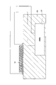
- FIG. 3 is a sectional view taken along line III-III in FIG. 2.
- FIG. 4 is a sectional view taken along line IV-IV in FIG. 2.
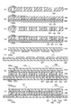
- FIG. 5 (a) to FIG. 5 (h) are cross-sectional views showing a manufacturing process of the heat flux sensor. It is a flowchart which shows the action
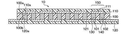
- the vehicle abnormality determination device of the present embodiment includes a heat flux sensor 10 and a control unit 20, and a battery or a vehicle engine control unit in which the heat flux sensor 10 is mounted on the vehicle. (Equipped with a heating element 30 such as (vehicle ECU: Electronic Control Unit)).
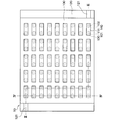
- the heat flux sensor 10 includes an insulating base material 100, a surface protection member 110, and a back surface protection member 120 that are integrated, and the first and second layers are integrated in the integrated body.
- the connection members 130 and 140 are alternately connected in series.
- the structure of the heat flux sensor 10 will be specifically described below.
- the surface protection member 110 is omitted for easy understanding.
- the insulating base material 100 is composed of a planar rectangular thermoplastic resin film represented by polyetheretherketone (PEEK), polyetherimide (PEI), and liquid crystal polymer (LCP).
- PEEK polyetheretherketone
- PEI polyetherimide
- LCP liquid crystal polymer
- first and second via holes 101 and 102 of the present embodiment have a cylindrical shape with a constant diameter from the front surface 100a of the insulating base material 100 toward the back surface 100b.
- the taper may be tapered with a diameter decreasing from 100a toward the back surface 100b.
- the insulating base 100 may have a tapered shape whose diameter decreases from the back surface 100b toward the front surface 100a, or may have a rectangular tube shape.
- a first interlayer connection member 130 is disposed in the first via hole 101, and a second interlayer connection member 140 is disposed in the second via hole 102.
- the first and second interlayer connection members 130 and 140 are alternately arranged on the insulating base material 100.
- the first and second interlayer connection members 130 and 140 are made of different metals so as to exhibit the Seebeck effect.
- the first interlayer connecting member 130 includes a metal compound (solid-sintered) in which a powder of a Bi—Sb—Te alloy constituting P-type maintains a crystal structure of a plurality of metal atoms before sintering. Sintered alloy).
- the second interlayer connecting member 140 is made of a metal compound obtained by solid-phase sintering so that Bi-Te alloy powder constituting N-type maintains the crystal structure of a plurality of metal atoms before sintering.
- the electromotive voltage can be increased by using a metal compound that is solid-phase sintered so as to maintain a predetermined crystal structure as the first and second interlayer connection members 130 and 140.
- FIG. 2 is not a cross-sectional view, the first and second interlayer connection members 130 and 140 are hatched for easy understanding.
- a surface protection member composed of a planar rectangular thermoplastic resin film represented by polyether ether ketone (PEEK), polyether imide (PEI), and liquid crystal polymer (LCP) on the surface 100a of the insulating substrate 100 110 is arranged.
- the surface protection member 110 has the same planar shape as the insulating base material 10, and a plurality of surface patterns 111 patterned with copper foil or the like on the side 110 a facing the insulating base material 100 are separated from each other. Is formed.
- Each surface pattern 111 is appropriately electrically connected to the first and second interlayer connection members 130 and 140, respectively.
- first and second layers of each set 150 are shown.
- the connection members 130 and 140 are connected to the same surface pattern 111. That is, the first and second interlayer connection members 130 and 140 of each set 150 are electrically connected via the surface pattern 111.
- one first interlayer connection member 130 and one second interlayer connection member 140 that are adjacent along the longitudinal direction of the insulating base material 100 (the left-right direction in FIG. 3) form a set 150. ing.
- a back surface protection member composed of a planar rectangular thermoplastic resin film represented by polyether ether ketone (PEEK), polyether imide (PEI), and liquid crystal polymer (LCP). 120 is arranged on the back surface 100b of the insulating base material 100.
- This back surface protection member 120 has a length in the longitudinal direction of the insulating base material 100 longer than that of the insulating base material 100, and the back surface 100 b of the insulating base material 100 so that both ends in the longitudinal direction protrude from the insulating base material 100. Is arranged.
- the back surface protection member 120 is formed with a plurality of back surface patterns 121 patterned with copper foil or the like on the one surface 120a facing the insulating substrate 100 so as to be separated from each other.
- Each back pattern 121 is appropriately electrically connected to the first and second interlayer connection members 130 and 140, respectively.
- the first interlayer connection member 130 of one set 150 and the second interlayer connection member 140 of the other set 150 are connected to the same back surface pattern 121. That is, the first and second interlayer connection members 130 and 140 are electrically connected via the same back surface pattern 121 across the set 150.
- the first and second interlayer connection members 130 and 140 that are adjacent along the direction orthogonal to the longitudinal direction are the same at the outer edge of the insulating substrate 100.
- the back surface pattern 121 is connected. More specifically, the adjacent first and second interlayer connection members 130 and 140 are the same on the back so that those connected in series via the front surface pattern 111 and the back surface pattern 121 are folded back in the longitudinal direction of the insulating substrate 100. It is connected to the pattern 121.
- the part used as the edge part of what was connected in series as mentioned above among the back surface patterns 121 is formed so that it may expose from the insulating base material 100, as FIG.2 and FIG.3 shows. And the part exposed from the insulating base material 100 among the back surface patterns 121 becomes a part that functions as a terminal connected to the control unit 20.
- the above is the configuration of the basic heat flux sensor 10 in the present embodiment.
- a heat flux sensor 10 outputs a sensor signal (electromotive voltage) corresponding to the heat flux passing through the heat flux sensor 10 in the thickness direction to the control unit 20. This is because when the heat flux changes, the electromotive voltage generated in the first and second interlayer connection members 130 and 140 alternately connected in series changes.
- the thickness direction of the heat flux sensor 10 is the stacking direction of the insulating base material 100, the front surface protection member 110, and the back surface protection member 120.
- an insulating substrate 100 is prepared, and a plurality of first via holes 101 are formed by a drill, a laser, or the like.
- each first via hole 101 is filled with a first conductive paste 131.
- a method (apparatus) for filling the first via hole 101 with the first conductive paste 131 for example, a method (apparatus) described in JP 2011-187619A may be employed.
- the insulating base material 100 is arranged on a holding table (not shown) with the suction paper 160 therebetween so that the back surface 100b faces the suction paper 160. Then, the first conductive paste 131 is filled into the first via hole 101 while the first conductive paste 131 is melted. As a result, most of the organic solvent of the first conductive paste 131 is adsorbed by the adsorption paper 160, and the alloy powder is placed in close contact with the first via hole 101.
- the adsorbing paper 160 may be made of a material that can absorb the organic solvent of the first conductive paste 131, and general high-quality paper or the like is used.
- the first conductive paste 131 is a paste obtained by adding an organic solvent such as paraffin having a melting point of 43 ° C. to a powder of Bi—Sb—Te alloy in which metal atoms maintain a predetermined crystal structure. Used. For this reason, when the first conductive paste 131 is filled, the surface 100a of the insulating base material 100 is heated to about 43 ° C.
- a plurality of second via holes 102 are formed in the insulating base material 100 by a drill, a laser, or the like. As described above, the second via holes 102 are formed alternately with the first via holes 101 so as to form a staggered pattern together with the first via holes 101.
- the second conductive paste 141 is filled in each second via hole 102.
- this process can be performed by the process similar to the said FIG.5 (b).
- the insulating substrate 100 is disposed again on the holding table (not shown) via the suction paper 160 so that the back surface 100b faces the suction paper 160, and then the second conductive paste 141 is filled in the second via hole 102. To do. As a result, most of the organic solvent of the second conductive paste 141 is adsorbed by the adsorption paper 160, and the alloy powder is placed in close contact with the second via hole 102.
- the second conductive paste 141 is a Bi-Te alloy powder in which metal atoms different from the metal atoms constituting the first conductive paste 131 maintain a predetermined crystal structure, and an organic solvent such as terpine having a melting point of room temperature. A paste made by adding is used. That is, the organic solvent constituting the second conductive paste 141 has a lower melting point than the organic solvent constituting the first conductive paste 131. And when filling the 2nd conductive paste 141, it is performed in the state by which the surface 100a of the insulating base material 100 was hold
- the state in which the organic solvent contained in the first conductive paste 131 is solidified means that the organic solvent remaining in the first via hole 101 without being adsorbed by the adsorption paper 160 in the step of FIG. That is.
- one surface 110a, 120a of the surface protection member 110 and the back surface protection member 120 that faces the insulating substrate 100 A copper foil or the like is formed. Then, by appropriately patterning this copper foil, the surface protection member 110 formed with a plurality of surface patterns 111 spaced apart from each other, and the back surface protection member 120 formed with a plurality of back surface patterns 121 spaced apart from each other. prepare.
- the back surface protection member 120, the insulating base material 100, and the surface protection member 110 are sequentially stacked to form a stacked body 170.
- the back surface protection member 120 is longer in the longitudinal direction than the insulating base material 100. And the back surface protection member 120 is arrange
- the laminate 170 is disposed between a pair of press plates (not shown), and is pressurized while being heated in a vacuum state from the upper and lower surfaces in the lamination direction. Integrate. Specifically, the first and second conductive pastes 131 and 141 are solid-phase sintered to form the first and second interlayer connection members 130 and 140, and the first and second interlayer connection members 130 and 140 are formed. The laminate 170 is integrated by applying pressure while heating so that the front surface pattern 111 and the back surface pattern 121 are connected.
- a cushioning material such as rock wool paper may be disposed between the laminate 170 and the press plate. As described above, the heat flux sensor 10 is manufactured.
- the control unit 20 is a vehicle ECU or the like configured using a CPU, various memories constituting a storage unit, peripheral devices, and the like, and is connected to the heat flux sensor 10, a voice unit (not shown), a display unit, and the like. Then, it is determined whether or not the measurement value measured by the heat flux sensor 10 is within a predetermined range, and when the measurement value is out of the predetermined range, the heating element is provided via audio means, display means, or the like. A warning to the effect that 30 abnormalities have occurred is notified to the occupant.
- the sensor signal (electromotive voltage) output from the heat flux sensor 10 may be determined as it is, or the heat flow obtained by converting the sensor signal into a heat flux value.
- the bundle value may be determined.
- the vehicle ECU constituting the control unit 20 is a separate member from the vehicle ECU that serves as the heating element 30.
- the vehicle abnormality determination device of the present embodiment is used with a heat flux sensor 10 attached to a heating element 30.
- control part 20 performs the following process for every predetermined period, for example, when the ignition switch in a vehicle is turned on.
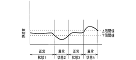
- the heating element 30 is constituted by the vehicle ECU as described above, and generates heat from the CPU constituting the vehicle ECU, various memories constituting the storage means, peripheral devices, and the like. And although the temperature of the heat generating body 30 is fluctuate
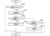
- step S200 it is determined whether or not the heating element 30 to which the heat flux sensor 10 is attached is operating (S200).
- the determination in step S200 is performed by exchanging signals to determine whether the vehicle ECU is operating.
- the process returns to the start (return).
- the heating element 30 is operating (S200: YES)
- the measured value measured by the heat flux sensor 10 is acquired (S210). Specifically, since a sensor signal (measured value) corresponding to the heat flux between the heating element 30 and the outside air is output from the heat flux sensor 10, this sensor signal (measured value) is acquired.
- the acquired measurement value is equal to or higher than the upper threshold value (S220). If the measurement value is equal to or higher than the upper threshold value as in state 4 in FIG. 7 (S220: YES), a warning is transmitted. (S230). Note that the acquired measured value is equal to or greater than the upper threshold value because each component of the vehicle ECU that is the heating element 30 does not operate normally due to failure or excessive operation, and abnormal heating is generated in the heating element 30. This is the case.
- the acquired measurement value is smaller than the upper limit threshold value (S220: NO)
- the determination of the measurement value in the processing of step S220 and step S240 may be performed by determining the sensor signal (electromotive voltage) output from the heat flux sensor 10 as it is, or the sensor signal is converted into heat flux.
- the heat flux may be determined by conversion.
- the warning in the processing of step S230 and step S250 informs the occupant that the heating element 30 is not in a normal state by driving sound means, display means, and the like.
- the sound means is driven to notify the occupant with an electronic sound.
- the display means is driven to display the occurrence of an abnormality on a liquid crystal display arranged in a part of an instrument display panel arranged in front of the steering wheel or in the center of the dashboard to notify the passenger.
- the heat flux between the heating element 30 and the outside air is detected by the heat flux sensor 10, and the abnormality determination of the heating element 30 is performed based on the sensor signal output from the heat flux sensor 10. It is carried out. For this reason, abnormality determination of the heating element 30 can be performed with high accuracy regardless of the use environment.
- the first and second via holes 101 and 102 are formed in the insulating base material 100 made of thermoplastic resin, and the first and second interlayer connection members 130 are formed in the first and second via holes 101 and 102. , 140 are arranged to constitute the heat flux sensor 10. Therefore, it is possible to increase the density of the first and second interlayer connection members 130 and 140 by appropriately changing the number, diameter, interval, and the like of the first and second via holes 101 and 102. Thereby, an electromotive voltage can be enlarged and the heat flux sensor 10 can be highly sensitive.
- the metal forming the first and second interlayer connection members 130 and 140 is a sintered alloy obtained by sintering a plurality of metal atoms while maintaining the crystal structure of the metal atoms.
- the insulating base material 100, the surface protection member 110, and the back surface protection member 120 are configured using a thermoplastic resin and have flexibility. For this reason, it can deform
- a temperature sensor that detects the surface temperature of the heating element 30 may be provided.
- both the control unit 20 and the heating element 30 are configured by a vehicle ECU.
- the vehicle ECU serving as the heating element 30 may perform the processing of the control unit 20. That is, the control unit 20 and the heating element 30 may be the same vehicle ECU.
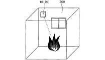
- the heat flux sensor is provided on a wall surface in the room and outputs a sensor signal corresponding to the heat flux between the wall surface and the air in the room, and the control unit is based on the sensor signal.
- the present invention relates to a fire alarm characterized by determining that a fire has occurred in the room when a heat flux between the wall surface and the air in the room is equal to or greater than a predetermined threshold.
- the insulating base material 100, the surface protection member 110, and the back surface protection member 120 are integrated, In the integrated member, a member in which the first and second interlayer connecting members 130 and 140 are alternately connected in series is used.
- the control unit 20 is configured using a CPU, various memories constituting the storage means, peripheral devices, etc., and is connected to audio means, illumination means, etc. (not shown).
- the example heat flux sensor 10 and the control unit 20 are provided on a wall surface 300 in a room, as shown in FIG. In this reference example, the heat flux sensor 10 and the control unit 20 are integrally packaged, but the heat flux sensor 10 and the control unit 20 may be separated.
- control unit 20 in this reference example will be described with reference to FIG.
- the operation of the control unit 20 is started, for example, when a resident turns on a switch (not shown), and performs the following processing every predetermined period.
- the measurement value measured by the heat flux sensor 10 is acquired (S400). Specifically, since the sensor signal (measured value) corresponding to the heat flux between the wall surface 300 and the indoor air is output from the heat flux sensor 10, this sensor signal (measured value) is acquired.
- the warning in the process of step S420 informs the resident that a fire has occurred by driving sound means, display means, and the like.
- the sound means is driven to notify the resident with an electronic sound.
- the occupant is also notified by driving the illumination means and turning on a warning lamp or the like.
- the process returns to the start (return).
- the determination of the measurement value in the process of step S410 may determine the sensor signal (electromotive voltage) output from the heat flux sensor 10 as it is, as in the first embodiment, or may use the sensor signal as the heat flux. And the heat flux may be determined.
- the present invention can also be applied to a fire alarm. And when this invention is applied to a fire alarm, a fire can be detected with high accuracy irrespective of the outside temperature.
- the heat flux sensor is attached to the human body and outputs a sensor signal corresponding to the heat flux between the human body and the outside air
- the control unit is configured to output the human body and the outside air based on the sensor signal. It is related with the abnormality determination apparatus of the human body which determines with the said human body having abnormality, when the heat flux between these is outside the predetermined range.
- the heat flux sensor 10 includes an insulating base material 100, a surface protection member 110, and a back surface protection member 120, as shown in FIGS.
- a member in which the first and second interlayer connecting members 130 and 140 are alternately connected in series is used.
- the control unit 20 is configured using a CPU, various memories constituting the storage means, peripheral devices, and the like, and is connected to audio means, display means, etc. (not shown).
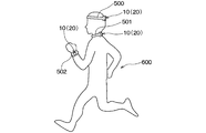
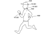
- the heat flux sensor 10 and the control unit 20 of this reference example are provided in a hair band 500, a neck warmer 501, and a wrist band 502 as shown in FIG. Is attached to the human body 600.
- FIG. 11B which is Reference Example 3
- the heat flux sensor 10 and the control unit 20 are provided in a jacket 503 and a hat 504, and the human body 600 is attached to the human body 600 by wearing them.
- the heat flux sensor 10 and the control unit 20 are integrally packaged, but the heat flux sensor 10 and the control unit 20 may be separated. Moreover, in FIG. 11A and FIG. 11B, the site
- control unit 20 in this reference example will be described with reference to FIG.
- the operation of the control unit 20 is started, for example, when a user turns on a switch (not shown), and performs the following processing every predetermined period.
- the measurement value measured by the heat flux sensor 10 is acquired (S700). Specifically, since a sensor signal (measured value) corresponding to the heat flux between the human body 600 and the outside air is output from the heat flux sensor 10, this sensor signal (measured value) is acquired.
- the acquired measurement value is equal to or greater than the upper threshold (S710). If the measurement value is equal to or greater than the upper threshold (S710: YES), a warning is transmitted (S720). ). Note that the acquired measured value is equal to or greater than the upper threshold value, for example, when the human body 600 is overworked while jogging.
- the acquired measurement value is smaller than the upper limit threshold value (S710: NO)
- a warning is transmitted similarly to the process of step S720 (S740). Note that the acquired measured value is equal to or lower than the lower limit threshold when heat radiation from the human body 600 is not properly performed and there is a possibility of heat stroke.
- the determination of the measurement value in the processing of step S710 and step S730 may be performed by determining the sensor signal (electromotive voltage) output from the heat flux sensor 10 as it is, as in the first embodiment. May be converted into a heat flux to determine the heat flux.
- the warning in the processing of step S720 and step S740 informs that the state of itself (human body 600) is abnormal by driving the voice means, the display means, and the like. .
- the sound means is driven to notify the user with an electronic sound.
- the display means is driven to display an abnormality on the liquid crystal display to notify the user.
- the present invention can also be applied to a human body abnormality determination device. And when this invention is applied to the abnormality determination apparatus of a human body, abnormality determination of a human body can be performed with high precision irrespective of outside temperature.
Landscapes
- Engineering & Computer Science (AREA)
- Physics & Mathematics (AREA)
- General Physics & Mathematics (AREA)
- Chemical & Material Sciences (AREA)
- Combustion & Propulsion (AREA)
- Mechanical Engineering (AREA)
- Investigating Or Analyzing Materials Using Thermal Means (AREA)
- Automation & Control Theory (AREA)
- Human Computer Interaction (AREA)
- Transportation (AREA)
- Surface Heating Bodies (AREA)
- Testing Of Devices, Machine Parts, Or Other Structures Thereof (AREA)
- Emergency Alarm Devices (AREA)
Priority Applications (4)
| Application Number | Priority Date | Filing Date | Title |
|---|---|---|---|
| US14/895,860 US9659416B2 (en) | 2013-06-04 | 2014-05-01 | Abnormality determination apparatus for vehicle |
| KR1020157036809A KR20160014026A (ko) | 2013-06-04 | 2014-05-01 | 차량용의 이상 판정 장치 |
| CN201480031443.5A CN105283755B (zh) | 2013-06-04 | 2014-05-01 | 车辆用的异常判定装置 |
| EP14807986.6A EP3006926B1 (en) | 2013-06-04 | 2014-05-01 | Abnormality determination apparatus for vehicle |
Applications Claiming Priority (4)
| Application Number | Priority Date | Filing Date | Title |
|---|---|---|---|
| JP2013-117751 | 2013-06-04 | ||
| JP2013117751 | 2013-06-04 | ||
| JP2013225557A JP5987811B2 (ja) | 2013-06-04 | 2013-10-30 | 車両用の異常判定装置 |
| JP2013-225557 | 2013-10-30 |
Publications (1)
| Publication Number | Publication Date |
|---|---|
| WO2014196294A1 true WO2014196294A1 (ja) | 2014-12-11 |
Family
ID=52007947
Family Applications (1)
| Application Number | Title | Priority Date | Filing Date |
|---|---|---|---|
| PCT/JP2014/062094 Ceased WO2014196294A1 (ja) | 2013-06-04 | 2014-05-01 | 車両用の異常判定装置 |
Country Status (7)
| Country | Link |
|---|---|
| US (1) | US9659416B2 (cg-RX-API-DMAC7.html) |
| EP (1) | EP3006926B1 (cg-RX-API-DMAC7.html) |
| JP (1) | JP5987811B2 (cg-RX-API-DMAC7.html) |
| KR (1) | KR20160014026A (cg-RX-API-DMAC7.html) |
| CN (1) | CN105283755B (cg-RX-API-DMAC7.html) |
| TW (1) | TWI576508B (cg-RX-API-DMAC7.html) |
| WO (1) | WO2014196294A1 (cg-RX-API-DMAC7.html) |
Cited By (6)
| Publication number | Priority date | Publication date | Assignee | Title |
|---|---|---|---|---|
| WO2015186330A1 (ja) * | 2014-06-03 | 2015-12-10 | 株式会社デンソー | 熱流分布測定装置 |
| JP2017187452A (ja) * | 2016-04-08 | 2017-10-12 | 株式会社デンソー | 監視装置 |
| EP3386269A4 (en) * | 2015-11-30 | 2018-12-12 | Denso Corporation | Heater plate, device for manufacturing heat flux sensor employing said heater plate, method of manufacturing said heater plate, and device for manufacturing said heater plate |
| JP2019114614A (ja) * | 2017-12-21 | 2019-07-11 | 株式会社デンソー | 熱交換器の異常検出装置 |
| EP3702751A1 (en) * | 2015-11-12 | 2020-09-02 | Denso Corporation | Operating-status diagnostic apparatus |
| EP3734250A1 (en) * | 2015-11-12 | 2020-11-04 | Denso Corporation | Diagnosis apparatus of assembly state |
Families Citing this family (18)
| Publication number | Priority date | Publication date | Assignee | Title |
|---|---|---|---|---|
| JP5761302B2 (ja) * | 2013-06-04 | 2015-08-12 | 株式会社デンソー | 車両用の快適温調制御装置 |
| JP5942960B2 (ja) * | 2013-06-04 | 2016-06-29 | 株式会社デンソー | 発熱量制御装置 |
| JP6481497B2 (ja) * | 2014-06-03 | 2019-03-13 | 株式会社デンソー | 温調制御装置 |
| JP6380168B2 (ja) * | 2015-03-02 | 2018-08-29 | 株式会社Soken | 熱式流量センサ |
| JP6406298B2 (ja) | 2015-10-05 | 2018-10-17 | 株式会社デンソー | 監視装置および異常診断装置 |
| US10393598B1 (en) * | 2015-12-03 | 2019-08-27 | FluxTeq LLC | Heat flux gage |
| DE112017001440B4 (de) | 2016-04-19 | 2024-11-28 | Gentherm Inc. | Klimatisierter Sitz mit Steuerung der Wärmestromdichte |
| JP6792987B2 (ja) * | 2016-09-29 | 2020-12-02 | 日本ドライケミカル株式会社 | 熱センサおよびその熱センサを用いた熱検知システム |
| KR102011020B1 (ko) | 2016-12-09 | 2019-08-16 | 고려대학교 산학협력단 | 해저드 모델 기반의 차량 네트워크 이상 징후 탐지 장치 |
| JP6443461B2 (ja) * | 2017-01-10 | 2018-12-26 | トヨタ自動車株式会社 | 発電装置の異常検出装置 |
| JP6988469B2 (ja) * | 2017-12-27 | 2022-01-05 | 株式会社デンソー | 歪み検出装置およびそれを用いた診断装置 |
| JP7362239B2 (ja) * | 2018-02-13 | 2023-10-17 | Ntn株式会社 | 軸受装置およびスピンドル装置 |
| DE112019005429T5 (de) * | 2018-10-31 | 2021-07-15 | Ntn Corporation | Lagervorrichtung |
| JP7411347B2 (ja) * | 2019-03-19 | 2024-01-11 | Ntn株式会社 | 潤滑油供給ユニットおよび軸受装置 |
| CN118728862A (zh) * | 2019-03-19 | 2024-10-01 | Ntn株式会社 | 润滑油供应单元和轴承装置 |
| JP7206141B2 (ja) * | 2019-03-25 | 2023-01-17 | Ntn株式会社 | 軸受装置 |
| FR3103219B1 (fr) * | 2019-11-19 | 2021-10-08 | Vitesco Technologies | Procédé de gestion des anomalies sporadiques d’un système de motorisation d’un véhicule automobile |
| DE102022120195A1 (de) * | 2022-08-10 | 2024-02-15 | Yazaki Systems Technologies Gmbh | System zur Stromübertragung innerhalb eines Fahrzeugs und Verfahren zum Betrieb des Systems |
Citations (8)
| Publication number | Priority date | Publication date | Assignee | Title |
|---|---|---|---|---|
| JPS6113121A (ja) * | 1984-06-28 | 1986-01-21 | Matsushita Electric Ind Co Ltd | 熱流センサ |
| JPS6296831A (ja) * | 1985-10-23 | 1987-05-06 | Eikou Seiki Sangyo Kk | 熱流計センサ−及びその製法 |
| JPH03127446U (cg-RX-API-DMAC7.html) * | 1990-04-06 | 1991-12-20 | ||
| JP2002328849A (ja) * | 2001-05-07 | 2002-11-15 | Denso Corp | 車両用電子制御装置 |
| JP2006275540A (ja) * | 2005-03-28 | 2006-10-12 | Fujitsu Ten Ltd | 空気流量計測装置の異常検出装置、及びエンジン制御システム |
| JP2009184639A (ja) | 2008-02-08 | 2009-08-20 | Denso Corp | 車両システム |
| JP2011187619A (ja) | 2010-03-08 | 2011-09-22 | Denso Corp | 貫通ビアへの導電材料充填装置およびその使用方法 |
| JP2012255717A (ja) * | 2011-06-09 | 2012-12-27 | Etou Denki Kk | 熱流センサ及び熱流センサの製造方法 |
Family Cites Families (7)
| Publication number | Priority date | Publication date | Assignee | Title |
|---|---|---|---|---|
| FR2413646A1 (fr) * | 1978-01-02 | 1979-07-27 | Saint Gobain | Fluxmetre thermique |
| US5195359A (en) * | 1989-07-18 | 1993-03-23 | Nippon Mining Co., Ltd. | Apparatus for detecting operating condition of internal-combustion engine |
| JP3782958B2 (ja) * | 2001-10-29 | 2006-06-07 | 助川電気工業株式会社 | 熱流束計 |
| KR100690926B1 (ko) * | 2006-02-03 | 2007-03-09 | 삼성전자주식회사 | 마이크로 열유속 센서 어레이 |
| US7510323B2 (en) * | 2006-03-14 | 2009-03-31 | International Business Machines Corporation | Multi-layered thermal sensor for integrated circuits and other layered structures |
| JP2008180491A (ja) | 2006-12-27 | 2008-08-07 | Kyoto Electron Mfg Co Ltd | 焼却炉 |
| WO2011044547A2 (en) * | 2009-10-09 | 2011-04-14 | Services Petroliers Schlumberger | Micro-thermal conductivity detector, method to fabricate such and chromatography system using such |
-
2013
- 2013-10-30 JP JP2013225557A patent/JP5987811B2/ja not_active Expired - Fee Related
-
2014
- 2014-05-01 WO PCT/JP2014/062094 patent/WO2014196294A1/ja not_active Ceased
- 2014-05-01 CN CN201480031443.5A patent/CN105283755B/zh not_active Expired - Fee Related
- 2014-05-01 US US14/895,860 patent/US9659416B2/en not_active Expired - Fee Related
- 2014-05-01 KR KR1020157036809A patent/KR20160014026A/ko not_active Ceased
- 2014-05-01 EP EP14807986.6A patent/EP3006926B1/en not_active Not-in-force
- 2014-05-13 TW TW103116846A patent/TWI576508B/zh not_active IP Right Cessation
Patent Citations (8)
| Publication number | Priority date | Publication date | Assignee | Title |
|---|---|---|---|---|
| JPS6113121A (ja) * | 1984-06-28 | 1986-01-21 | Matsushita Electric Ind Co Ltd | 熱流センサ |
| JPS6296831A (ja) * | 1985-10-23 | 1987-05-06 | Eikou Seiki Sangyo Kk | 熱流計センサ−及びその製法 |
| JPH03127446U (cg-RX-API-DMAC7.html) * | 1990-04-06 | 1991-12-20 | ||
| JP2002328849A (ja) * | 2001-05-07 | 2002-11-15 | Denso Corp | 車両用電子制御装置 |
| JP2006275540A (ja) * | 2005-03-28 | 2006-10-12 | Fujitsu Ten Ltd | 空気流量計測装置の異常検出装置、及びエンジン制御システム |
| JP2009184639A (ja) | 2008-02-08 | 2009-08-20 | Denso Corp | 車両システム |
| JP2011187619A (ja) | 2010-03-08 | 2011-09-22 | Denso Corp | 貫通ビアへの導電材料充填装置およびその使用方法 |
| JP2012255717A (ja) * | 2011-06-09 | 2012-12-27 | Etou Denki Kk | 熱流センサ及び熱流センサの製造方法 |
Non-Patent Citations (1)
| Title |
|---|
| See also references of EP3006926A4 |
Cited By (14)
| Publication number | Priority date | Publication date | Assignee | Title |
|---|---|---|---|---|
| JP2016011950A (ja) * | 2014-06-03 | 2016-01-21 | 株式会社デンソー | 熱流分布測定装置 |
| WO2015186330A1 (ja) * | 2014-06-03 | 2015-12-10 | 株式会社デンソー | 熱流分布測定装置 |
| EP3702751A1 (en) * | 2015-11-12 | 2020-09-02 | Denso Corporation | Operating-status diagnostic apparatus |
| US10859447B2 (en) | 2015-11-12 | 2020-12-08 | Denso Corporation | Operating-status diagnostic apparatus |
| US10845256B2 (en) | 2015-11-12 | 2020-11-24 | Denso Corporation | Diagnosis apparatus of assembly state |
| EP3734250A1 (en) * | 2015-11-12 | 2020-11-04 | Denso Corporation | Diagnosis apparatus of assembly state |
| EP3386269A4 (en) * | 2015-11-30 | 2018-12-12 | Denso Corporation | Heater plate, device for manufacturing heat flux sensor employing said heater plate, method of manufacturing said heater plate, and device for manufacturing said heater plate |
| US10782194B2 (en) | 2015-11-30 | 2020-09-22 | Denso Corporation | Heater plate, apparatus for manufacturing heat flux sensor using the heater plate, method of manufacturing the heater plate and apparatus for manufacturing the heater plate |
| WO2017175851A1 (ja) * | 2016-04-08 | 2017-10-12 | 株式会社デンソー | 監視装置 |
| KR102124399B1 (ko) | 2016-04-08 | 2020-06-18 | 가부시키가이샤 덴소 | 감시장치 |
| KR20180122427A (ko) * | 2016-04-08 | 2018-11-12 | 가부시키가이샤 덴소 | 감시장치 |
| JP2017187452A (ja) * | 2016-04-08 | 2017-10-12 | 株式会社デンソー | 監視装置 |
| JP2019114614A (ja) * | 2017-12-21 | 2019-07-11 | 株式会社デンソー | 熱交換器の異常検出装置 |
| JP7087376B2 (ja) | 2017-12-21 | 2022-06-21 | 株式会社デンソー | 熱交換器の異常検出装置 |
Also Published As
| Publication number | Publication date |
|---|---|
| US9659416B2 (en) | 2017-05-23 |
| US20160125671A1 (en) | 2016-05-05 |
| CN105283755A (zh) | 2016-01-27 |
| EP3006926B1 (en) | 2018-04-11 |
| TW201520418A (zh) | 2015-06-01 |
| EP3006926A1 (en) | 2016-04-13 |
| EP3006926A4 (en) | 2017-01-11 |
| JP2015014586A (ja) | 2015-01-22 |
| TWI576508B (zh) | 2017-04-01 |
| KR20160014026A (ko) | 2016-02-05 |
| CN105283755B (zh) | 2017-11-28 |
| JP5987811B2 (ja) | 2016-09-07 |
Similar Documents
| Publication | Publication Date | Title |
|---|---|---|
| JP5987811B2 (ja) | 車両用の異常判定装置 | |
| JP5999066B2 (ja) | 振動検出器 | |
| JP6303973B2 (ja) | 状態検出センサ | |
| JP6011514B2 (ja) | 液面高さ検出計 | |
| JP6485206B2 (ja) | 熱流分布測定装置 | |
| JP6380168B2 (ja) | 熱式流量センサ | |
| JP6070506B2 (ja) | 生体検知器、車両用着座検知器およびシートベルト非着用警告システム | |
| JP5942960B2 (ja) | 発熱量制御装置 | |
| CN105074407B (zh) | 用于测量周围介质压力的电容式压力测量元件 | |
| JP6369379B2 (ja) | 質量流量計および速度計 | |
| US10543722B2 (en) | Flexible tire sensor device and method | |
| KR20140053636A (ko) | 타이어 공기압 모니터링 시스템 | |
| JP6969665B2 (ja) | 深部体温計 | |
| WO2018139041A1 (ja) | 生理的熱量の計測器 |
Legal Events
| Date | Code | Title | Description |
|---|---|---|---|
| WWE | Wipo information: entry into national phase |
Ref document number: 201480031443.5 Country of ref document: CN |
|
| 121 | Ep: the epo has been informed by wipo that ep was designated in this application |
Ref document number: 14807986 Country of ref document: EP Kind code of ref document: A1 |
|
| WWE | Wipo information: entry into national phase |
Ref document number: 14895860 Country of ref document: US |
|
| NENP | Non-entry into the national phase |
Ref country code: DE |
|
| WWE | Wipo information: entry into national phase |
Ref document number: 2014807986 Country of ref document: EP |
|
| ENP | Entry into the national phase |
Ref document number: 20157036809 Country of ref document: KR Kind code of ref document: A |