WO2014192495A1 - ディスクブレーキ - Google Patents
ディスクブレーキ Download PDFInfo
- Publication number
- WO2014192495A1 WO2014192495A1 PCT/JP2014/061992 JP2014061992W WO2014192495A1 WO 2014192495 A1 WO2014192495 A1 WO 2014192495A1 JP 2014061992 W JP2014061992 W JP 2014061992W WO 2014192495 A1 WO2014192495 A1 WO 2014192495A1
- Authority
- WO
- WIPO (PCT)
- Prior art keywords
- disk
- spring
- friction pad
- bent
- pad
- Prior art date
- Legal status (The legal status is an assumption and is not a legal conclusion. Google has not performed a legal analysis and makes no representation as to the accuracy of the status listed.)
- Ceased
Links
Images




Classifications
-
- F—MECHANICAL ENGINEERING; LIGHTING; HEATING; WEAPONS; BLASTING
- F16—ENGINEERING ELEMENTS AND UNITS; GENERAL MEASURES FOR PRODUCING AND MAINTAINING EFFECTIVE FUNCTIONING OF MACHINES OR INSTALLATIONS; THERMAL INSULATION IN GENERAL
- F16D—COUPLINGS FOR TRANSMITTING ROTATION; CLUTCHES; BRAKES
- F16D66/00—Arrangements for monitoring working conditions, e.g. wear, temperature
- F16D66/02—Apparatus for indicating wear
-
- F—MECHANICAL ENGINEERING; LIGHTING; HEATING; WEAPONS; BLASTING
- F16—ENGINEERING ELEMENTS AND UNITS; GENERAL MEASURES FOR PRODUCING AND MAINTAINING EFFECTIVE FUNCTIONING OF MACHINES OR INSTALLATIONS; THERMAL INSULATION IN GENERAL
- F16D—COUPLINGS FOR TRANSMITTING ROTATION; CLUTCHES; BRAKES
- F16D65/00—Parts or details
- F16D65/02—Braking members; Mounting thereof
- F16D65/04—Bands, shoes or pads; Pivots or supporting members therefor
- F16D65/092—Bands, shoes or pads; Pivots or supporting members therefor for axially-engaging brakes, e.g. disc brakes
- F16D65/095—Pivots or supporting members therefor
- F16D65/097—Resilient means interposed between pads and supporting members or other brake parts
- F16D65/0972—Resilient means interposed between pads and supporting members or other brake parts transmitting brake reaction force, e.g. elements interposed between torque support plate and pad
-
- F—MECHANICAL ENGINEERING; LIGHTING; HEATING; WEAPONS; BLASTING
- F16—ENGINEERING ELEMENTS AND UNITS; GENERAL MEASURES FOR PRODUCING AND MAINTAINING EFFECTIVE FUNCTIONING OF MACHINES OR INSTALLATIONS; THERMAL INSULATION IN GENERAL
- F16D—COUPLINGS FOR TRANSMITTING ROTATION; CLUTCHES; BRAKES
- F16D65/00—Parts or details
- F16D65/02—Braking members; Mounting thereof
- F16D65/04—Bands, shoes or pads; Pivots or supporting members therefor
- F16D65/092—Bands, shoes or pads; Pivots or supporting members therefor for axially-engaging brakes, e.g. disc brakes
- F16D65/095—Pivots or supporting members therefor
- F16D65/097—Resilient means interposed between pads and supporting members or other brake parts
- F16D65/0973—Resilient means interposed between pads and supporting members or other brake parts not subjected to brake forces
- F16D65/0974—Resilient means interposed between pads and supporting members or other brake parts not subjected to brake forces acting on or in the vicinity of the pad rim in a direction substantially transverse to the brake disc axis
- F16D65/0977—Springs made from sheet metal
-
- F—MECHANICAL ENGINEERING; LIGHTING; HEATING; WEAPONS; BLASTING
- F16—ENGINEERING ELEMENTS AND UNITS; GENERAL MEASURES FOR PRODUCING AND MAINTAINING EFFECTIVE FUNCTIONING OF MACHINES OR INSTALLATIONS; THERMAL INSULATION IN GENERAL
- F16D—COUPLINGS FOR TRANSMITTING ROTATION; CLUTCHES; BRAKES
- F16D65/00—Parts or details
- F16D65/02—Braking members; Mounting thereof
- F16D65/04—Bands, shoes or pads; Pivots or supporting members therefor
- F16D65/092—Bands, shoes or pads; Pivots or supporting members therefor for axially-engaging brakes, e.g. disc brakes
- F16D65/095—Pivots or supporting members therefor
- F16D65/097—Resilient means interposed between pads and supporting members or other brake parts
- F16D65/0973—Resilient means interposed between pads and supporting members or other brake parts not subjected to brake forces
- F16D65/0979—Resilient means interposed between pads and supporting members or other brake parts not subjected to brake forces acting on the rear side of the pad or an element affixed thereto, e.g. spring clips securing the pad to the brake piston or caliper
Definitions
- the present invention relates to a disc brake that applies a braking force to a vehicle such as an automobile.
- a disc brake provided in a vehicle such as an automobile includes an attachment member attached to a non-rotating portion of the vehicle, and a pair of friction pads supported by the attachment member and pressed against both surfaces of the disc by supplying hydraulic pressure to the caliper.
- a biasing spring (so-called anti-rattle spring) provided between the friction pad and the mounting member and biasing the friction pad toward the outlet side (circumferential direction) in the rotational direction when the disk moves forward. It is configured and a biasing spring having a function of detecting a wear state of a friction pad is known (see, for example, Patent Document 1).
- the disc brake provided with the urging spring employed in the above-described prior art has a problem that the detection sound generated due to the wear state of the friction pad cannot be obtained sufficiently.
- the present invention has been made in view of the above-mentioned problems of the prior art, and an object of the present invention is to provide a disc brake in which a sufficient detection sound can be obtained.
- a disc brake according to the present invention has a friction receiving pad that is fixed to a vehicle across a disc and receives a torque during braking, and is provided opposite to both sides of the disc.
- the caliper that presses against the disk has a mounting member that is slidably provided, and the friction pad is supported by the mounting member on both sides in the circumferential direction of the disk, and on a side surface portion that contacts the torque receiving surface of the mounting member.
- a biasing means fixedly attached to the back plate, and a biasing means connected to the mounting portion and extending in a direction away from the disk.
- 1 extension A bent portion that is formed in an arc shape in a direction away from the disk on the front end side of the first extending portion and is bent so that the front end faces the disk side, and a front end of the bent portion And a second extension portion elastically deformed on the mounting member side in a direction approaching the disk from the side, and the tip of the second extension portion is worn by a predetermined amount of the friction material Sometimes it comes into contact with the disk, and the bent portion is set to be higher in rigidity than the first boundary portion between the first extending portion and the bent portion.
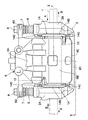
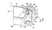
- FIG. 2 is a partially broken front view of the disc brake as viewed from the direction of arrows II-II in FIG.
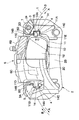
- FIG. 3 is a rear view of the disc brake shown in FIG. 2.
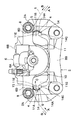
- FIG. 2 is a partially broken plan view showing an attachment member, a friction pad, a pad spring, an urging spring and the like with the caliper in FIG. 1 removed.
- FIG. 5 is a cross-sectional view of the mounting member, friction pad, pad spring, biasing spring, and the like as seen from the direction of arrows VI-VI in FIG. 4.
- 1 indicates a rotating disk.
- This disk 1 rotates in the direction of arrow A in FIG. 1 together with wheels (not shown) when the vehicle travels in the forward direction, for example. When retreating, it rotates in the direction indicated by arrow B.
- Reference numeral 2 denotes a carrier as an attachment member attached to a non-rotating portion of the vehicle.
- the carrier 2 is spaced apart in the rotation direction (circumferential direction) of the disk 1 and straddles the outer periphery of the disk 1 as shown in FIGS.
- the pair of arms 2A, 2A extending in the axial direction of the disk 1 and the proximal end side of each arm 2A are connected so as to be integrated, and the position at the inner side of the disk 1 is It is comprised from the thick support part 2B etc. which are fixed to the non-rotating part of a vehicle.
- the carrier 2 is integrally formed with a reinforcing beam 2C that connects the distal ends of the arms 2A and 2A to each other at a position on the outer side of the disk 1 in a bow shape as shown in FIG.
- the arm portions 2A and 2A of the carrier 2 are integrally connected by the support portion 2B on the inner side of the disk 1 and are integrally connected by the reinforcing beam 2C on the outer side.
- a disc path portion 3 extending in an arc along the outer periphery (rotation locus) of the disc 1 is formed at the intermediate portion of the arm portion 2A in the axial direction of the disc 1 as shown in FIGS. .
- Inner side and outer side pad guides 4 are formed on both sides of the disk 1 in the disk path portion 3 in the axial direction.
- Each arm 2A is provided with a pin hole 2D as shown in FIGS. In these pin holes 2D, slide pins 7 described later are slidably fitted.
- the pad guide 4 is formed as a concave groove having a rectangular shape corresponding to the shape of an ear portion 11A of the friction pad 10 described later. That is, it extends in the direction of sliding displacement. Note that the shape of the groove need not be a complete rectangle.
- the pad guide 4 fits the ears 11A and 11B so as to sandwich the ears 11A and 11B of the friction pad 10 to be described later from above and below (disk radial direction).
- the friction pad 10 is guided in the disk axial direction through these ear portions 11A and 11B.
- a torque receiving surface 5 as a so-called torque receiving portion is formed on the back side wall surface of the pad guide 4.
- the torque receiving surface 5 is used by the friction pad 10 to receive the braking torque generated during the brake operation via the ear portions 11A and 11B.
- the left pad guide 4 positioned on the rotation direction outlet side (hereinafter referred to as the unwinding side) of the disk 1 rotating in the arrow A direction,
- the torque receiving surface 5 on the bottom side receives braking torque received by the friction pad 10 (described later) from the disc 1 during brake operation via the ear portion 11B of the back metal 11 and the guide plate portion 14A of the pad spring 14 (described later).
- the bottom side of the pad guide 4 positioned on the turning-in side (hereinafter referred to as the turning-in side) of the disk 1 rotating in the direction indicated by the arrow A, that is, the torque receiving surface 5 is an ear part of the friction pad 10 during brake operation. It is in a state slightly separated from 11A.
- the caliper 6 is slidably provided on the carrier 2. As shown in FIG. 1, the caliper 6 has an inner leg portion 6A provided on the inner side which is one side of the disc 1 and an inner leg portion so as to straddle the outer peripheral side of the disc 1 between each arm portion 2A of the carrier 2. A bridge portion 6B extending from 6A to the outer side, which is the other side of the disk 1, and extends radially inward from the outer side, which is the front end side of the bridge portion 6B, with the front end side being bifurcated. The outer leg portion 6C is formed.
- the inner leg portion 6A of the caliper 6 is formed with a cylinder (not shown) in which a piston is slidably fitted. Further, the inner leg portion 6A is provided with a pair of attachment portions 6D and 6D protruding in the left and right directions in FIGS. Each mounting portion 6D supports the entire caliper 6 slidably on each arm portion 2A of the carrier 2 via a sliding pin 7 described later.
- the sliding pin 7 is fastened to each mounting portion 6D of the caliper 6 using bolts 8 as shown in FIG.
- the tip side of each sliding pin 7 extends toward the pin hole 2D of each arm 2A of the carrier 2, and is slidably inserted into each pin hole 2D of the carrier 2 as illustrated in FIG. It is fitted.
- Protective boots 9 and 9 are respectively attached between the arm portions 2A and the sliding pins 7 to prevent rainwater and the like from entering between the sliding pins 7 and the pin holes 2D of the arm portions 2A. It is out.
- the friction pad 10 is disposed opposite to both sides of the disk 1. As shown in FIGS. 1 to 6, the friction pad 10 is provided with a plate-shaped back metal 11 extending in a substantially fan shape in the circumferential direction (rotation direction) of the disk 1, and fixed to the surface side of the back metal 11. A lining 12 or the like as a friction material that comes into frictional contact with the surface of the disk 1 is used.
- the back metal 11 of the friction pad 10 is provided with ear portions 11A and 11B having convex shapes as fitting portions on side surfaces located on both sides in the circumferential direction of the disk 1.
- the ears 11A and 11B of the back metal 11 constitute a torque transmission unit that transmits the braking torque received by the friction pad 10 from the disc 1 to the torque receiving surface 5 of the carrier 2 when the vehicle is braked.
- the ears 11A and 11B of the friction pad 10 are formed symmetrically to the left and right as shown in FIGS. 2 and 3, for example, and have the same shape.
- One ear portion 11A is arranged on the turn-in side (turn-in side) of the disc 1 that rotates in the direction of arrow A when the vehicle moves forward, and the other ear portion 11B is on the exit side in the rotation direction of the disc 1 ( It is arranged on the delivery side.
- Biasing springs 15 are provided on the ears 11A located on the side of the disk 1 in the left and right ears 11A and 11B that serve as torque transmission parts of the friction pad 10.
- the back metal 11 of the friction pad 10 is formed with flat surface portions 11C and 11D on both sides in the length direction, that is, on the side surfaces located on the turn-in side and the turn-out side of the disc 1.
- the flat surface portions 11C and 11D extend outward in the radial direction of the disk 1 in a direction substantially perpendicular to the protruding direction of the ear portions 11A and 11B.
- the back metal 11 of the friction pad 10 is provided with caulking portions 11E and 11E located closer to the base ends (roots) of the ear portions 11A and 11B.
- the caulking portion 11 ⁇ / b> E is provided so as to protrude toward one surface (hereinafter referred to as a surface 11 ⁇ / b> F) on which the lining 12 of the back metal 11 is provided.
- the crimping portion 11E positioned on the side of the disk 1 is subjected to crimping in order to fix an urging spring 15 to be described later to the back metal 11 of the friction pad 10. .
- a concave groove 13 is provided in the ear portion 11A of the back metal 11. As shown in FIGS. 7 and 8, the concave groove 13 is formed by partially cutting the distal end (protrusion side) end surface 11A1 of the ear portion 11A into an L shape, and one of the biasing springs 15 described later. A storage groove for storing the portion is configured. Then, the groove depth h of the concave groove 13 with respect to the end surface 11A1 ⁇ of the ear portion 11A is set to a size approximately twice as large as the plate thickness t of an urging spring 15 described later, as shown in FIG.
- the concave groove 13 is disposed at a position closer to the outer side in the radial direction than the center position in the width direction (disk radial direction) of the ear portion 11A.
- the friction pad 10 can share parts on the inner side and the outer side of the disk 1, reducing the number of parts of the disk brake and eliminating the manufacturing complexity. It becomes possible.
- Pad springs 14 and 14 are attached to each arm 2 ⁇ / b> A of the carrier 2.
- the pad springs 14 and 14 elastically support the friction pads 10 on the inner side and the outer side, respectively, and smooth the sliding displacement of these friction pads 10.
- the pad spring 14 is formed by bending (press forming) a stainless steel plate or the like having spring properties as shown in FIGS.
- the pad spring 14 includes a pair of guide plate portions 14A, a connecting plate portion 14B, and a radial urging plate portion 14C.
- the pair of guide plate portions 14A is formed by being bent into a substantially U shape so as to be fitted in each pad guide 4 of the carrier 2, and is formed by being separated from the inner side and the outer side of the disc 1 by hand. Yes.
- the connecting plate portion 14B is formed to extend in the axial direction so as to straddle the outer peripheral side of the disc 1 in order to connect the guide plate portions 14A integrally on the inner side and the outer side of the disc 1.
- the radial urging plate portions 14C and 14C are integrally formed in the radially inner portion of the disk 1 of each guide plate portion 14A.
- Each guide plate portion 14A of the pad spring 14 is fitted and mounted in each pad guide 4 of the carrier 2 as shown in FIGS. 2, 3, 5, and 6, and the back metal 11 of the friction pad 10 is projected. It has a function of guiding in the axial direction of the disk 1 through the shaped ear portions 11A and 11B.
- Each radial urging plate portion 14 ⁇ / b> C elastically contacts the ear portions 11 ⁇ / b> A and 11 ⁇ / b> B of each friction pad 10 (back metal 11) in each pad guide 4 of the carrier 2, thereby 11 is urged toward the radially outer side of the disk 1. Thereby, the backlash of each friction pad 10 is suppressed.
- the urging spring 15 includes an ear portion 11A (side surface portion) that becomes the disk insertion side when the vehicle moves forward among the side surface portions (ear portions 11A and 11B) of the back metal 11 of the friction pad 10, and the carrier 2 that opposes the ear portion 11A. It is provided between the torque receiving surface 5 (facing surface of the mounting member).
- the biasing spring 15 constitutes a biasing unit that biases the friction pad 10 toward the unwinding side of the disk 1.
- the urging spring 15 is formed, for example, by bending (press forming) a stainless steel plate having a spring property having a thickness of t and a constant thickness as shown in FIGS.
- the spring constant k1 of the urging spring 15 is set to the relationship of the following formula 1.
- the spring constant k according to the equation (2) is an inherent characteristic when the caliper 6 vibrates as a rigid body with the caliper 6 attached to the carrier 2 (attachment member) when the caliper 6 is regarded as a vibration source as a cause of brake squeal. It is obtained from the frequency f and the mass m of the friction pad 10.
- the spring constant k1 of the urging spring 15 is set to a value that is smaller than the spring constant k according to Equation 2 and larger than zero by appropriately adjusting the plate thickness t, for example.
- the spring constant k according to Equation 2 is obtained as follows when the natural frequency f is 200 Hz and the mass m is 0.2 kg.
- the natural frequency f is determined by performing an excitation test in which the caliper 6 is vibrated with a hammer or the like with the caliper 6 attached to the vehicle and the carrier 2 and the vibration generated at this time is measured with a measuring instrument. , Identification is possible. Further, the natural frequency of the caliper 6 measured by such an excitation test has a width of 200 Hz to 500 Hz.
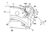
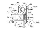
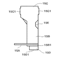
- the biasing spring 15 includes an attachment portion 15A, a first extension portion 15B, a bent portion 15C, a second extension portion 15D, and a boundary portion 15E.
- the attachment portion 15A is fixed and attached to the surface 11F side of the friction pad 10 (back metal 11) by a caulking portion 11E.
- the first extension portion 15B is narrower than the attachment portion 15A (the horizontal direction in FIG. 10 is the width and the vertical direction is the longitudinal direction), and the base end side is connected to the attachment portion 15A (integral formation). Then, it extends toward the other surface (back surface 11G) opposite to the one surface (front surface 11F) of the back metal 11 through the concave groove 13 in a direction away from the disk 1.
- the base end side connected to the attachment portion 15A of the first extension portion 15B has a curved portion 15B1 that approaches the disk 1 once.
- the boundary portion 15E is a boundary between the first extending portion 15B and the bent portion 15C, and is a narrow portion that is narrower than the first extending portion 15B, and the rigidity in the folding direction is reduced. Yes. Further, the width is equal to or less than that of the second extending portion 15D.
- the bent portion 15C is integrally formed on the front end side of the first extending portion 15B, and is bent into an arc shape protruding toward the direction away from the disk 1 on the back surface 11G side of the back metal 11, and is turned back. The side faces toward the disk 1.
- the width of the bent portion 15C is wider than that of the first extending portion 15B and the second extending portion 15D, and the rigidity in the direction in which the arc-shaped curvature changes is enhanced. Furthermore, the reinforcement part 15C1 bent 90 degree
- the second extending portion 15D extends from the front end side of the bent portion 15C to the surface 11F side of the back metal 11 in a direction approaching the disk 1, and the guide plate portion 14A of the pad spring 14 is provided on the torque receiving surface 5 of the carrier 2. It is made to contact (elastic contact) in an elastically deformed state. Further, the tip thereof is a contact portion 15D1 that comes into contact with the disk 1 when the lining 12 is worn.
- the contact portion 15D1 has a tip bent in the A direction in which the vehicle rotates forward.
- the width of the second extending portion 15D is narrower than that of the bent portion 15C and is approximately the same as that of the first extending portion 15B, and is increased by a press so as to increase the rigidity in the bending direction.
- Ribs 15D2 are formed to extend in the direction.
- the urging spring 15 is cantilevered on the friction pad 10 as shown in FIG. 8 when the brake 15 is not operated or when the vehicle is advanced by fixing the mounting portion 15A to the ear 11A side of the back metal 11. It is supported by.
- the ear portion 11A of the friction pad 10 comes into contact with the torque receiving surface 5 of the carrier 2 (guide plate portion 14A of the pad spring 14), and the biasing spring 15 is large.
- the second extending portion 15D is housed in the concave groove 13 of the ear portion 11A together with the first extending portion 15B so as to maintain the cantilever state.
- the biasing spring 15 is disposed at a position that is closer to the outside in the radial direction than the center position in the width direction (the radial direction of the disk) of the ear portion 11A.
- the biasing spring 15 can bias the friction pad 10 toward the disk delivery side at a position that is closer to the outer side in the radial direction than the center position in the width direction of the ear portion 11A. It can be suppressed.
- the disc brake according to the present embodiment has the above-described configuration, and the operation thereof will be described next.
- the brake fluid pressure is supplied to the inner leg portion 6A (cylinder) of the caliper 6 to cause the piston to slide and displace toward the disc 1, whereby the inner friction pad 10 is moved to the disc 1. Press on one side.
- the entire caliper 6 is slid and displaced toward the inner side with respect to the arm portion 2A of the carrier 2, and the outer leg portion 6C is the friction pad 10 on the outer side. Is pressed against the other side of the disk 1.
- the inner and outer friction pads 10 strongly hold the disk 1 rotating in the direction indicated by the arrow A in FIG. 1 to FIG. 3 (when the vehicle moves forward) from both sides in the axial direction.
- the disc 1 can be given a braking force.
- the brake operation is released, the hydraulic pressure supply to the piston is stopped, so that the inner and outer friction pads 10 are separated from the disk 1 and return to the non-braking state again.
- the ear 11A located on the side of the disk 1 in the ear 11A, 11B of the friction pad 10 is illustrated by the biasing spring 15. 2, 3, 5 and 6, the friction pad 10 is constantly urged by a weak force toward the delivery side of the disk 1 (the direction of arrow A in FIG. 2).
- edge part 11B located in the delivery side of the disc 1 is elastically pressed against the torque receiving surface 5 of the pad guide 4 through the guide plate part 14A of the pad spring 14 by the biasing force at this time.
- the biasing spring 15 provided between the ear portion 11A on the disk insertion side and the torque receiving surface 5 prevents the friction pad 10 from rattling in the circumferential direction of the disk 1 due to vibration or the like when the vehicle travels. It can be regulated by.
- the braking torque rotation torque in the direction of arrow A
- the arm portion 2A torque receiving surface 5 of the pad guide 4 on the delivery side. I can accept it.
- the ear portion 11B located on the disk delivery side of the friction pad 10 continues to contact the torque receiving surface 5 of the pad guide 4 via the guide plate portion 14A.
- the ear 11B on the delivery side is in contact with the guide plate portion 14A by the action of the biasing spring 15 before the brake operation and has no clearance, so that the friction pad 10 is moved by the braking torque. There will be no noise.
- each radial urging plate portion 14C is urged outward in the radial direction of the disk 1.
- edge parts 11A and 11B of the friction pad 10 can be elastically pressed to the disk radial direction outer side surface (upper surface in the figure) side of 14 A of guide plates.
- the ear part 11B located on the disk delivery side of the friction pad 10 is located on the disk delivery side by the action of the biasing spring 15 provided on the ear part 11A on the delivery side.
- the braking torque from the disk 1 is received with the torque receiving surface 5 while being elastically pressed against the torque receiving surface 5 of the pad guide 4 (the guide plate portion 14A of the pad spring 14).
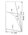
- the spring constant k2 when the deformation of the arm 2A is regarded as a spring is, for example, in FIG.
- each characteristic line extends from the reference point shown in FIG.
- a characteristic line 19 indicated by a one-dot chain line indicates the characteristic of the spring constant of the anti-rattle spring of Patent Document 1.
- the characteristic line 19 has a cantilevered spring characteristic before the inflection point 19A, and the spring constant is larger than the spring constant k.
- the friction pad will resonate with the caliper that vibrates at the natural frequency f to generate brake noise.
- the inflection point 19A and the subsequent spring characteristics are in a cantilever state, and the spring constant is larger than the spring constant in a cantilever state.
- the spring constant at the time of such a double-supported spring characteristic is also larger than the spring constant k. Therefore, there is a possibility that the friction pad will resonate with the caliper that vibrates at the natural frequency f to generate brake noise.
- the spring constant k1 of the biasing spring 15 is set to be relatively small, immediately after the brake operation, the ear portion 11A of the friction pad 10 (back metal 11) is connected to the torque receiving surface 5 of the carrier 2 (guide of the pad spring 14). The brake torque from the disk 1 is received with the torque receiving surface 5 by contacting the plate portion 14A). Even if the ear portion 11A abuts against the torque receiving surface 5 and the urging spring 15 is greatly bent and deformed as shown in FIG. 10, the urging spring 15 is maintained in a cantilevered state. For this reason, the apparent spring constant k1 of the urging spring 15 rises like a characteristic line portion 18A of the characteristic line 18 shown in FIG.
- the characteristic is substantially parallel to k2 (characteristic line 16 shown in FIG. 12). Therefore, the resonance frequency that leads to the squealing of the urging spring 15 can be avoided, and the occurrence of so-called brake squealing including slow braking squealing can be suppressed.
- a slow braking squeal and a low frequency range squeal are likely to occur in a disc brake attached to the rear of the vehicle, and it is effective to attach the biasing spring 15 of the present embodiment to the rear disc brake.
- the spring constant k1 of the urging spring 15 is used, resonance also occurs with respect to the natural frequency (about 2000 Hz) of the three-diameter node mode of the disk 1 when the disk 1 is regarded as a vibration source as a cause of brake squeal. It is possible to avoid the occurrence of brake noise by avoiding the frequency.
- the urging spring 15 is bent by a metal plate having a spring property (for example, a stainless steel plate), so that the mounting portion 15A, the first extension portion 15B, the bending portion are bent as described above.
- the spring constant k1 ⁇ ⁇ ⁇ of the urging spring 15 is set to the above equation 1 by appropriately adjusting the plate thickness t of the urging spring 15 because it is formed as an integral body consisting of the portion 15C and the second extending portion 15D. It can be set to satisfy the relationship.
- the urging spring 15 is arranged at a position closer to the outer side in the radial direction than the center position in the width direction (disk radial direction) of the ear portion 11A.
- the biasing spring 15 can bias the friction pad 10 in a direction in which the moment accompanying the braking torque becomes positive at a position that is closer to the outside in the radial direction than the center position in the width direction of the ear portion 11A. It is possible to suppress the occurrence of couple loss during braking.
- the biasing spring 15 is formed between the ear portion 11A of the friction pad 10 (back metal 11) 11A and 11B, which is the disk insertion side when the vehicle moves forward, and the torque receiving surface 5 of the carrier 2 facing the ear portion 11A. It can be arranged in a compact manner.
- the second extending portion 15D of the biasing spring 15 is formed so as to be in a cantilever state even when the end surface 11A1 of the ear portion 11A abuts against the torque receiving surface 5 (guide plate portion 14A) when the vehicle moves backward. Therefore, the spring constant k1 of the urging spring 15 can be easily set to a small value as in the above formulas 1 to 3, and abnormal noise such as brake squealing is generated during braking in the vehicle reverse direction. Can be suppressed.
- the urging spring 15 is provided on the surface 11F side of the back pad 11 of the friction pad 10 on which the lining 12 is provided, the vehicle space can be used effectively, and the spring necessary for the urging spring 15 is provided. It becomes easy to secure constants and necessary loads (spring force). Further, by providing the urging spring 15 fixed to the back metal 11 of the friction pad 10, the urging spring 15 can be attached to the carrier 2 in a sub-assembly state in which the urging spring 15 is pre-assembled to the friction pad 10. Workability at the time can be improved.
- the attaching portion 15A is fixedly attached to the front surface 11F side of the back metal 11 and attached to the back surface 11G of the disc 1 from the front end side of the attaching portion 15A toward the back surface 11G side of the back metal 11.
- a first extension portion 15B extending in a direction away from the first extension portion 15B, and a first extension portion 15B that is formed on the leading end side of the first extension portion 15B and folded in an arc shape toward the disc 1 on the back surface 11G side of the backing metal 11.
- the bent portion 15C is bent, and the second extending portion 15D extends from the front end side of the bent portion 15C in a direction approaching the disk 1 and elastically contacts the torque receiving surface 5 side of the carrier 2 in an elastically deformed state. is doing.
- the spring length of the urging spring 15 can be set to a sufficient length by the mounting portion 15A, the first extending portion 15B, the bent portion 15C, and the second extending portion 15D.
- the spring constant necessary for the spring 15 (the above-described equations 1 and 2) can be easily secured. And it becomes easy to ensure the required load (spring force) as the urging spring 15, and the vehicle space can be used effectively with the urging spring 15 attached to the friction pad 10.
- the biasing spring 15 formed using a stainless steel plate or the like has a guide plate portion of the pad spring 14 on the torque receiving surface 5 of the carrier 2 such that the second extending portion 15D located on the tip (free end) side thereof. Since it is elastically contacted via 14A in an elastically deformed state, the sliding contact between them can be made smooth, and the occurrence of so-called judder can be satisfactorily suppressed.
- the bent portion 15C of the urging spring 15 has an arc shape at a position on the inner side in the disk circumferential direction (arrow C direction) from the end surface 11A1A of the ear portion 11A of the back metal 11. Since it is configured to be bent, the bent portion 15C of the urging spring 15 and the like can be easily arranged by effectively utilizing the space formed by the pad guide 4 of the carrier 2. In addition, the spring length of the urging spring 15 can be sufficiently ensured, and the urging force (spring force) can be stabilized.
- the urging spring 15 has a contact portion 15D1 that abuts against the disc 1, the urging spring 15 is also used as a wear detection sensor for detecting wear of the lining 12 by the urging spring 15 as a single component. And the number of parts can be reduced.
- the inventors of the present invention have studied to increase the frictional noise when the biasing spring 15 is a wear detection sensor.
- the natural frequency ⁇ r in the rotational direction K and the natural vibration in the vertical direction J shown in FIG. It was found that by making several ⁇ t closer, self-excited vibration is likely to occur and the detection sound is enhanced.
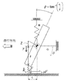
- FIG. 13 shows a motion model of a rigid bar traveling on a friction surface. This takes into account the degree of freedom in parallel translation in the vertical direction and the degree of rotational freedom around the center of gravity when the rigid simple bar travels on the plate.
- the mechanism of self-excited vibration of a simple rod on the friction surface is described below.
- Mass of simple bar Moment of inertia of simple bar: D Support rigidity in translation direction of simple bar: Support rigidity in rotation direction of simple bar: Contact rigidity between simple bar and friction surface: kc Simple bar and friction Coefficient of friction with the surface: ⁇ Vertical drag from the friction surface: Vertical distance of the contact portion from the F center of gravity position: Distance of travel direction of the contact portion from the center of gravity position of p: q Tilt of the simple rod: Vertical direction of the ⁇ simple rod Displacement: y Simple rod rotation angle: ⁇
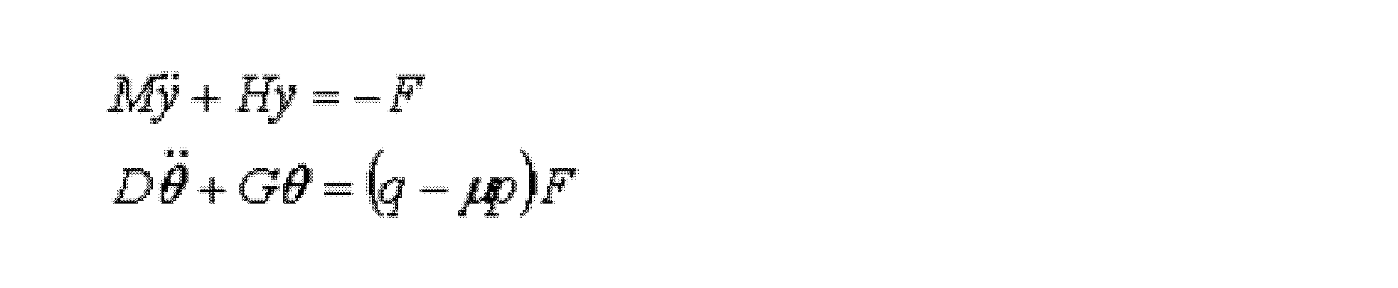
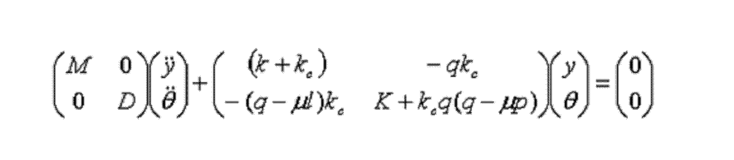
- the translational and rotational equations of motion are as follows.
- Equation 5 is obtained as follows.
- the reaction force from the friction surface may be obtained by multiplying the contact stiffness kc by the displacement amount according to Hooke's law.
- kc ⁇ y becomes the spring force due to translation.
- the spring is extended by the line Z.
- the length of the line Z is q ⁇ tan ⁇ q ⁇ .
- the amount of displacement is ya- ⁇ due to the contraction in translation and the extension direction in rotation, so the vertical drag (reaction force) F is determined as shown in Equation 5.
- the right side of the equation of motion of rotational motion (lower part of equation 4) is the moment around the center of gravity due to the reaction force F and friction force ⁇ F from the friction surface.
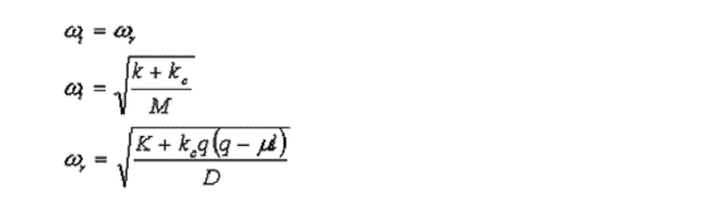
- Equation 7 kc can be regarded as zero when the simple bar and the friction surface are separated, so ⁇ t becomes ⁇ (H / M). It can be seen that ⁇ t increases as the contact stiffness increases when the simple rod and the friction surface contact. On the other hand, when ⁇ r is separated from the simple bar and the friction surface, kc is zero and ⁇ (G / D) as in the above case. When the simple rod and the friction surface are in contact with each other, it can be seen that ⁇ r decreases as the contact rigidity increases under the condition of Equation 8.
- the natural frequency ⁇ t of translational freedom is lower than the natural frequency ⁇ r of rotational freedom (non-contact: ⁇ t ⁇ r), and Therefore, it is required to keep the separation frequency close to each other so that the natural frequencies of the contacts coincide with each other at an early stage.
- a general urging spring comprising a bent portion and a second extending portion extending in a direction approaching the disk from the front end side of the bent portion and elastically deforming to the mounting member side in a state of elastic deformation.
- the rotational direction K By reducing the natural frequency ⁇ r of or increasing the natural frequency ⁇ t in the vertical direction J, it is possible to bring the natural vibration closer. Note that the natural frequency ⁇ r in the rotation direction K may be decreased and the natural frequency ⁇ t in the vertical direction J may be increased.
- the natural frequency ⁇ r in the rotational direction K is reduced by reducing the rigidity of the boundary portion 15E that most affects the rigidity in the rotational direction K. Therefore, the rigidity was lowered by narrowing the width of the boundary portion 15E. Although the number of manufacturing steps is long, the rigidity may be lowered by reducing the thickness of the boundary portion 15E.
- the natural frequency ⁇ t in the rotational direction K is increased by increasing the rigidity of the bent portion 15C that most affects the rigidity in the vertical direction J. Therefore, the rigidity is increased by increasing the width of the bent portion 15C. Furthermore, the reinforcement part 15C1 bent 90 degree
- ribs such as 15D2 may be provided in the bent portion 15C, and there is a method of increasing the thickness.
- the base end side of the biasing spring 15 is fixed to the ear portion 11A of the back metal 11, and the tip end side (extending portion 15D) of the biasing spring 15 is provided on the torque receiving surface 5 of the carrier 2. It is configured to be elastically contacted.
- the present invention is not limited to this.
- an urging spring biasing means
- the pad guide 4 which makes concave shape is formed in the arm part 2A of the carrier 2, and the case where the ear
- the present invention is not limited to this.
- a concave fitting portion may be provided on the back metal of the friction pad, and a convex pad guide may be provided on the arm portion of the attachment member.
- the present invention is not limited to this.
- the present invention can also be applied to a disc brake of a type in which a torque receiving surface as a torque receiver is provided at a position separated from the pad guide (a position different from the pad guide). is there.
- the urging means is provided between the torque transmission portion of the friction pad and the torque receiving surface of the mounting member that is provided on the disk insertion side when the vehicle moves forward, and the torque transmitting portion and the torque receiving surface.
- the friction pad is urged toward the disk delivery side by an extension portion that elastically contacts either one.
- the urging means can be compactly arranged between the torque transmitting portion of the friction pad and the torque transmitting portion on the disk insertion side when the vehicle moves forward, and the torque receiving surface of the mounting member.
- the urging force that urges toward the disk delivery side can be stabilized.
- the extending portion of the urging means is formed so that the cantilever state is maintained until the torque transmitting portion comes into contact with the torque receiving surface of the mounting member when the vehicle moves backward.
- the spring constant of the urging means can be easily set to a smaller value, and the occurrence of abnormal noise such as brake noise during braking in the vehicle reverse direction can be reduced.
- the biasing means is fixed to the back of the friction pad.
- the biasing means can be attached to the attachment member in a sub-assy state in which the biasing means is pre-assembled to the friction pad, and workability during assembly can be improved.
- the urging means is configured to be fixedly provided on one side of the friction pad back metal provided with the lining. Therefore, it becomes easy to secure a spring constant and a necessary load (spring force) necessary for the urging means, and the limited vehicle space can be used effectively.
- the urging means has a mounting portion fixedly attached to one surface side of the back metal, and a base end side connected to the mounting portion and directed to the other surface side opposite to the one surface of the back metal.
- a first extending portion extending in a direction away from the disk, and folded in an arc shape toward the direction approaching the disk on the other surface side of the back metal formed on the front end side of the first extending portion.
- a bent part and a second extension part extending in a direction approaching the disk from the front end side of the bent part and elastically deforming to the attachment member side are provided.
- the spring length of the urging means can be sufficiently secured by the first extending portion, the bent portion and the second extending portion, and the spring constant necessary for the urging means can be easily ensured and necessary. It is easy to secure the load (spring force), and the limited vehicle space can be used effectively.
- the bending portion of the urging means is configured to be bent in an arc shape at a position on the inner side in the circumferential direction of the disk with respect to the end face facing the torque receiving surface of the mounting member in the torque transmission portion of the back metal.
- the urging means is configured to be fixedly provided on the other side of the friction pad back metal opposite to the lining. Accordingly, the urging means can be fixedly provided on the other surface side of the back metal, and the area occupied by the lining provided on the one surface side of the back metal can be increased.
- the urging means is formed on a pad spring provided on the mounting member.
- the urging means can be formed integrally with the pad spring, the number of parts can be reduced, and workability at the time of attachment can be improved.
Landscapes
- Engineering & Computer Science (AREA)
- General Engineering & Computer Science (AREA)
- Mechanical Engineering (AREA)
- Braking Arrangements (AREA)
Abstract
Description





Claims (5)
- ディスクを跨いで車両に固定されて、制動時のトルクを受けるトルク受面が形成され、前記ディスクの両面に対向して設けられる摩擦パッドを前記ディスクに押圧するキャリパが前記ディスクの軸方向に摺動可能に設けられる取付部材を有し、
前記摩擦パッドは、前記取付部材にディスクの周方向両側で支持され、前記取付部材のトルク受面と当接する側面部にトルク伝達部が形成された裏板と、該裏板の一面側に固着して前記ディスクに当接して摩擦力を発生する摩擦材と、前記摩擦パッドをディスクの回出側に向けて付勢する付勢手段と、を有し、
前記付勢手段は、
前記裏板に固定して取付けられる取付部と、
該取付部に基端側が接続され前記ディスクから離間する方向に延出された第1の延出部と、
該第1の延出部の先端側に前記ディスクから離間する方向に向けて弧状に形成され先端が前記ディスク側に向くように折曲げられた折曲げ部と、
該折曲げ部の先端側から前記ディスクに近付く方向に延び前記取付部材側に弾性変形状態で弾接する第2の延出部とを有し、
該第2の延出部の先端は、前記摩擦材が所定量摩耗したときに前記ディスクに当接するようになっており、
前記折曲げ部は、前記第1の延出部と前記折曲げ部との境界部位よりも剛性が高く設定されてなることを特徴とするディスクブレーキ。 - 前記第1の境界部位は、前記第1の延出部よりも剛性が低く、前記折曲げ部は、前記第1の延出部よりも剛性が高く設定されてなることを特徴とする請求項1に記載のディスクブレーキ。
- 前記付勢手段は、金属板で構成され、
前記第1の境界部位は、前記第1の延出部よりも幅が狭い幅狭部となっていることを特徴とする請求項1または2に記載のディスクブレーキ。 - 前記付勢手段は、金属板で構成され、
前記折曲げ部は、前記第1の延出部よりも幅が広い幅広部となっていることを特徴とする請求項1乃至3のいずれかに記載のディスクブレーキ。 - 前記付勢手段は、金属板で構成され、
前記折曲げ部は、幅方向の少なくとも片側が長手方向に沿って折り曲げた補強部を有することを特徴とする請求項4に記載のディスクブレーキ。
Priority Applications (4)
| Application Number | Priority Date | Filing Date | Title |
|---|---|---|---|
| CN201480031142.2A CN105247238B (zh) | 2013-05-31 | 2014-04-30 | 盘式制动器 |
| DE112014002586.0T DE112014002586B4 (de) | 2013-05-31 | 2014-04-30 | Scheibenbremse |
| JP2015519755A JP6086980B2 (ja) | 2013-05-31 | 2014-04-30 | ディスクブレーキ |
| US14/894,433 US9797464B2 (en) | 2013-05-31 | 2014-04-30 | Disk brake |
Applications Claiming Priority (2)
| Application Number | Priority Date | Filing Date | Title |
|---|---|---|---|
| JP2013-116366 | 2013-05-31 | ||
| JP2013116366 | 2013-05-31 |
Publications (1)
| Publication Number | Publication Date |
|---|---|
| WO2014192495A1 true WO2014192495A1 (ja) | 2014-12-04 |
Family
ID=51988533
Family Applications (1)
| Application Number | Title | Priority Date | Filing Date |
|---|---|---|---|
| PCT/JP2014/061992 Ceased WO2014192495A1 (ja) | 2013-05-31 | 2014-04-30 | ディスクブレーキ |
Country Status (5)
| Country | Link |
|---|---|
| US (1) | US9797464B2 (ja) |
| JP (1) | JP6086980B2 (ja) |
| CN (1) | CN105247238B (ja) |
| DE (1) | DE112014002586B4 (ja) |
| WO (1) | WO2014192495A1 (ja) |
Cited By (3)
| Publication number | Priority date | Publication date | Assignee | Title |
|---|---|---|---|---|
| US9797464B2 (en) | 2013-05-31 | 2017-10-24 | Hitachi Automotive Systems, Ltd. | Disk brake |
| WO2019039501A1 (ja) * | 2017-08-25 | 2019-02-28 | 株式会社アドヴィックス | ブレーキパッド摩耗検出器 |
| CN118548304A (zh) * | 2024-07-29 | 2024-08-27 | 万向钱潮股份公司 | 一种刹车装置及车辆 |
Families Citing this family (4)
| Publication number | Priority date | Publication date | Assignee | Title |
|---|---|---|---|---|
| IT201800006504A1 (it) * | 2018-06-20 | 2019-12-20 | Molla per pastiglie d’attrito in una pinza per freno a disco | |
| IT201800006506A1 (it) | 2018-06-20 | 2019-12-20 | Molla per pastiglie d’attrito in una pinza per freno a disco | |
| DE112019003736B4 (de) * | 2018-07-25 | 2025-03-20 | Hitachi Astemo, Ltd. | Scheibenbremse und Bremsklotz |
| DE102019205500B4 (de) * | 2019-04-16 | 2025-06-12 | Zf Active Safety Gmbh | Bremsbelagrückstelleinrichtung für eine Fahrzeugbremsanlage |
Citations (4)
| Publication number | Priority date | Publication date | Assignee | Title |
|---|---|---|---|---|
| JPS5119277A (ja) * | 1974-06-28 | 1976-02-16 | Bendix Corp | |
| JPS57140934A (en) * | 1981-02-20 | 1982-08-31 | Toyota Motor Corp | Abrasion limit alarm of friction pad for disc brake |
| JPH0552381U (ja) * | 1991-12-17 | 1993-07-13 | トキコ株式会社 | パッド摩耗警報装置 |
| JP2012211664A (ja) * | 2011-03-31 | 2012-11-01 | Hitachi Automotive Systems Ltd | ディスクブレーキ |
Family Cites Families (21)
| Publication number | Priority date | Publication date | Assignee | Title |
|---|---|---|---|---|
| US3977499A (en) * | 1974-06-28 | 1976-08-31 | The Bendix Corporation | Disc brake shoe anti-rattle clip |
| JPS5386970A (en) | 1977-01-10 | 1978-07-31 | Aisin Seiki Co Ltd | Disk brake |
| US4460067A (en) * | 1981-02-20 | 1984-07-17 | Toyota Jidosha Kogyo Kabushiki Kaisha | Pad-wear-limit warning device for disc brake |
| JPH0547304Y2 (ja) * | 1989-03-20 | 1993-12-13 | ||
| JPH0552381A (ja) | 1991-08-27 | 1993-03-02 | Sanyo Electric Co Ltd | 空気調和機 |
| JP3213191B2 (ja) * | 1995-01-27 | 2001-10-02 | トキコ株式会社 | ディスクブレーキ |
| JP3273436B2 (ja) * | 1996-07-09 | 2002-04-08 | トキコ株式会社 | ディスクブレーキ |
| JP3816588B2 (ja) * | 1996-07-09 | 2006-08-30 | 株式会社日立製作所 | ディスクブレーキ |
| JPH10331883A (ja) | 1997-05-29 | 1998-12-15 | Aisin Seiki Co Ltd | ディスクブレーキ |
| SE516374C2 (en) | 2000-02-22 | 2002-01-08 | Workpiece controlled shaping of metal, preferably in the form of plates or bands, comprises heating the workpiece across notches or zones to reduce locally the tensile strength | |
| JP4284676B2 (ja) * | 2003-04-07 | 2009-06-24 | 株式会社日立製作所 | ディスクブレーキ |
| JP4332049B2 (ja) * | 2004-03-05 | 2009-09-16 | 本田技研工業株式会社 | ディスクブレーキ |
| US7318503B2 (en) * | 2004-04-26 | 2008-01-15 | Akebono Corporation (North America) | Pad retaining clips |
| US7040464B1 (en) * | 2005-03-18 | 2006-05-09 | Kelsey-Hayes Company | Brake shoe assembly and disc brake assembly including such a brake shoe assembly |
| DE102008022200B4 (de) * | 2008-05-06 | 2025-03-13 | Zf Active Safety Gmbh | Bremsbelaganordnung für Scheibenbremsen |
| JP5047200B2 (ja) * | 2009-01-21 | 2012-10-10 | 日立オートモティブシステムズ株式会社 | ディスクブレーキ |
| JP5277089B2 (ja) | 2009-06-30 | 2013-08-28 | 日立オートモティブシステムズ株式会社 | ディスクブレーキ |
| JP5583533B2 (ja) * | 2009-09-28 | 2014-09-03 | 日立オートモティブシステムズ株式会社 | ディスクブレーキ |
| JP5916875B2 (ja) * | 2012-09-25 | 2016-05-11 | 日立オートモティブシステムズ株式会社 | ディスクブレーキ |
| DE112014002586B4 (de) | 2013-05-31 | 2022-12-29 | Hitachi Astemo, Ltd. | Scheibenbremse |
| JP6134926B2 (ja) * | 2013-06-28 | 2017-05-31 | 日立オートモティブシステムズ株式会社 | ディスクブレーキ |
-
2014
- 2014-04-30 DE DE112014002586.0T patent/DE112014002586B4/de active Active
- 2014-04-30 US US14/894,433 patent/US9797464B2/en active Active
- 2014-04-30 JP JP2015519755A patent/JP6086980B2/ja active Active
- 2014-04-30 WO PCT/JP2014/061992 patent/WO2014192495A1/ja not_active Ceased
- 2014-04-30 CN CN201480031142.2A patent/CN105247238B/zh active Active
Patent Citations (4)
| Publication number | Priority date | Publication date | Assignee | Title |
|---|---|---|---|---|
| JPS5119277A (ja) * | 1974-06-28 | 1976-02-16 | Bendix Corp | |
| JPS57140934A (en) * | 1981-02-20 | 1982-08-31 | Toyota Motor Corp | Abrasion limit alarm of friction pad for disc brake |
| JPH0552381U (ja) * | 1991-12-17 | 1993-07-13 | トキコ株式会社 | パッド摩耗警報装置 |
| JP2012211664A (ja) * | 2011-03-31 | 2012-11-01 | Hitachi Automotive Systems Ltd | ディスクブレーキ |
Cited By (3)
| Publication number | Priority date | Publication date | Assignee | Title |
|---|---|---|---|---|
| US9797464B2 (en) | 2013-05-31 | 2017-10-24 | Hitachi Automotive Systems, Ltd. | Disk brake |
| WO2019039501A1 (ja) * | 2017-08-25 | 2019-02-28 | 株式会社アドヴィックス | ブレーキパッド摩耗検出器 |
| CN118548304A (zh) * | 2024-07-29 | 2024-08-27 | 万向钱潮股份公司 | 一种刹车装置及车辆 |
Also Published As
| Publication number | Publication date |
|---|---|
| DE112014002586B4 (de) | 2022-12-29 |
| DE112014002586T5 (de) | 2016-03-31 |
| JP6086980B2 (ja) | 2017-03-01 |
| CN105247238B (zh) | 2017-09-29 |
| US20160116011A1 (en) | 2016-04-28 |
| US9797464B2 (en) | 2017-10-24 |
| CN105247238A (zh) | 2016-01-13 |
| JPWO2014192495A1 (ja) | 2017-02-23 |
Similar Documents
| Publication | Publication Date | Title |
|---|---|---|
| JP5277089B2 (ja) | ディスクブレーキ | |
| JP6086980B2 (ja) | ディスクブレーキ | |
| US20170102042A1 (en) | A spring of a caliper of a disc brake | |
| CN108291597B (zh) | 盘式制动器 | |
| JP6818098B2 (ja) | ディスクブレーキ | |
| JP4577600B2 (ja) | ディスクブレーキ | |
| JP2015031325A (ja) | ディスクブレーキ | |
| JP6746789B2 (ja) | ディスクブレーキ | |
| US11835100B2 (en) | Disc brake | |
| JP2015010624A (ja) | 車両用ディスクブレーキ | |
| JP6579969B2 (ja) | ディスクブレーキ | |
| US12181008B2 (en) | Disc brake | |
| JP5576965B2 (ja) | ディスクブレーキ及び摩擦パッド | |
| JP5759793B2 (ja) | ディスクブレーキ | |
| JP6757592B2 (ja) | ディスクブレーキ | |
| WO2019012805A1 (ja) | ディスクブレーキ | |
| JP6149273B2 (ja) | ディスクブレーキ | |
| JP2017150589A (ja) | ディスクブレーキ | |
| JP6212758B2 (ja) | ディスクブレーキ | |
| JP2013113420A (ja) | ディスクブレーキ | |
| JP2009041618A (ja) | ディスクブレーキ装置用パッドクリップおよびディスクブレーキ装置 | |
| JP2021173304A (ja) | ディスクブレーキ | |
| JP2008138738A (ja) | ディスクブレーキ | |
| JP2007092961A (ja) | 浮動型ディスクブレーキ |
Legal Events
| Date | Code | Title | Description |
|---|---|---|---|
| 121 | Ep: the epo has been informed by wipo that ep was designated in this application |
Ref document number: 14803889 Country of ref document: EP Kind code of ref document: A1 |
|
| ENP | Entry into the national phase |
Ref document number: 2015519755 Country of ref document: JP Kind code of ref document: A |
|
| WWE | Wipo information: entry into national phase |
Ref document number: 14894433 Country of ref document: US |
|
| WWE | Wipo information: entry into national phase |
Ref document number: 112014002586 Country of ref document: DE |
|
| 122 | Ep: pct application non-entry in european phase |
Ref document number: 14803889 Country of ref document: EP Kind code of ref document: A1 |