WO2014192359A1 - 吸気装置 - Google Patents
吸気装置 Download PDFInfo
- Publication number
- WO2014192359A1 WO2014192359A1 PCT/JP2014/056354 JP2014056354W WO2014192359A1 WO 2014192359 A1 WO2014192359 A1 WO 2014192359A1 JP 2014056354 W JP2014056354 W JP 2014056354W WO 2014192359 A1 WO2014192359 A1 WO 2014192359A1
- Authority
- WO
- WIPO (PCT)
- Prior art keywords
- piece
- intake passage
- surge tank
- intake
- wall
- Prior art date
- Legal status (The legal status is an assumption and is not a legal conclusion. Google has not performed a legal analysis and makes no representation as to the accuracy of the status listed.)
- Ceased
Links
Images


Classifications
-
- F—MECHANICAL ENGINEERING; LIGHTING; HEATING; WEAPONS; BLASTING
- F02—COMBUSTION ENGINES; HOT-GAS OR COMBUSTION-PRODUCT ENGINE PLANTS
- F02M—SUPPLYING COMBUSTION ENGINES IN GENERAL WITH COMBUSTIBLE MIXTURES OR CONSTITUENTS THEREOF
- F02M35/00—Combustion-air cleaners, air intakes, intake silencers, or induction systems specially adapted for, or arranged on, internal-combustion engines
- F02M35/10—Air intakes; Induction systems
- F02M35/1034—Manufacturing and assembling intake systems
- F02M35/10354—Joining multiple sections together
-
- F—MECHANICAL ENGINEERING; LIGHTING; HEATING; WEAPONS; BLASTING
- F02—COMBUSTION ENGINES; HOT-GAS OR COMBUSTION-PRODUCT ENGINE PLANTS
- F02M—SUPPLYING COMBUSTION ENGINES IN GENERAL WITH COMBUSTIBLE MIXTURES OR CONSTITUENTS THEREOF
- F02M35/00—Combustion-air cleaners, air intakes, intake silencers, or induction systems specially adapted for, or arranged on, internal-combustion engines
- F02M35/10—Air intakes; Induction systems
- F02M35/10006—Air intakes; Induction systems characterised by the position of elements of the air intake system in direction of the air intake flow, i.e. between ambient air inlet and supply to the combustion chamber
- F02M35/10026—Plenum chambers
- F02M35/10039—Intake ducts situated partly within or on the plenum chamber housing
-
- F—MECHANICAL ENGINEERING; LIGHTING; HEATING; WEAPONS; BLASTING
- F02—COMBUSTION ENGINES; HOT-GAS OR COMBUSTION-PRODUCT ENGINE PLANTS
- F02M—SUPPLYING COMBUSTION ENGINES IN GENERAL WITH COMBUSTIBLE MIXTURES OR CONSTITUENTS THEREOF
- F02M35/00—Combustion-air cleaners, air intakes, intake silencers, or induction systems specially adapted for, or arranged on, internal-combustion engines
- F02M35/10—Air intakes; Induction systems
- F02M35/10091—Air intakes; Induction systems characterised by details of intake ducts: shapes; connections; arrangements
- F02M35/10144—Connections of intake ducts to each other or to another device
-
- F—MECHANICAL ENGINEERING; LIGHTING; HEATING; WEAPONS; BLASTING
- F02—COMBUSTION ENGINES; HOT-GAS OR COMBUSTION-PRODUCT ENGINE PLANTS
- F02M—SUPPLYING COMBUSTION ENGINES IN GENERAL WITH COMBUSTIBLE MIXTURES OR CONSTITUENTS THEREOF
- F02M35/00—Combustion-air cleaners, air intakes, intake silencers, or induction systems specially adapted for, or arranged on, internal-combustion engines
- F02M35/10—Air intakes; Induction systems
- F02M35/104—Intake manifolds
- F02M35/112—Intake manifolds for engines with cylinders all in one line
-
- F—MECHANICAL ENGINEERING; LIGHTING; HEATING; WEAPONS; BLASTING
- F02—COMBUSTION ENGINES; HOT-GAS OR COMBUSTION-PRODUCT ENGINE PLANTS
- F02M—SUPPLYING COMBUSTION ENGINES IN GENERAL WITH COMBUSTIBLE MIXTURES OR CONSTITUENTS THEREOF
- F02M35/00—Combustion-air cleaners, air intakes, intake silencers, or induction systems specially adapted for, or arranged on, internal-combustion engines
- F02M35/10—Air intakes; Induction systems
- F02M35/1034—Manufacturing and assembling intake systems
- F02M35/10347—Moulding, casting or the like
Definitions
- the present invention relates to an intake system.
- an intake system in which a surge tank and an intake passage are configured by a plurality of pieces.
- Such an intake device is disclosed, for example, in Japanese Unexamined Patent Publication No. 2012-251518.
- JP 2012-251518 A there is disclosed a three-piece intake system of an upper piece positioned at the upper side, a middle piece positioned at the middle, and a lower piece positioned at the lower side.
- the upper piece and the middle piece constitute the downstream portion of the intake passage
- the middle piece and the lower piece constitute the upstream portion of the surge tank and the intake passage.
- the intake passage communicates with the surge tank on the upstream side, and is connected to the intake port of the engine at a flange portion provided at the end of the downstream portion.
- the flange portion is integrally formed with the middle piece.
- the pieces of the intake system are made of resin and joined to each other by vibration welding. That is, the side wall of the surge tank is configured by vibration-welding the lower end surface (welding line) of the upper side wall portion of the middle piece and the upper end surface (welding line) of the lower side wall portion of the lower piece.
- the intake passage of the middle piece provided with the side wall of the surge tank constituted by the upper side wall portion of the middle piece and the lower side wall portion of the lower piece and the flange portion
- the side walls of the downstream portion are formed to be separated from each other and for bonding.
- the flange portion which is the connection portion with the intake port of the internal combustion engine is spaced apart from the side wall of the middle tank surge tank. Since it is provided, a structure susceptible to vibration in which a vibration transmitting portion (flange portion) at the time of operation of the internal combustion engine and a heavy portion (surge tank side portion) of the intake system are connected at a long distance As a result, it is difficult to suppress the vibration of the intake system.
- the present invention has been made to solve the problems as described above, and one object of the present invention is to provide an air intake device capable of achieving downsizing and suppressing vibration.
- an intake system includes a first piece, a surge tank, an intermediate piece joined to the first piece, and an upstream portion of an intake passage communicating with the surge tank. And a second piece joined to the middle piece, wherein the first piece and the middle piece constitute an intake passage downstream portion in communication with the intake passage upstream portion, and the second piece is further downstream of the intake passage And a flange portion connecting the portion and the intake port of the internal combustion engine.
- the second piece joined to the intermediate piece includes the intake passage upstream portion in communication with the surge tank, the intake passage downstream portion and the intake port of the internal combustion engine
- the side wall near the upstream portion of the intake passage communicating with the surge tank and the side wall of the flange portion are connected at least in the joint surface with the intermediate piece in the second piece. It can be a side wall. Therefore, also on the intermediate piece side joined to the second piece, the side wall of the surge tank and the side wall of the intake passage downstream portion are connected to form a single side wall and joined to the single side wall of the second piece be able to.
- the vibration transmission portion (flange portion) and the weight portion (surge tank side portion) of the intake device are connected at a short distance in the second piece. As a result, the vibration of the entire intake system can be suppressed.
- the flange portion of the second piece and the wall portion on the flange portion side of the surge tank of the second piece or the upstream portion of the intake passage are adjacently integrated.
- a first joint is provided which is joined to the intermediate piece in the adjacent and integral part.
- the surge tank of the intermediate piece and the downstream portion of the intake passage of the intermediate piece are disposed adjacent to each other via a single first partition, and the first partition is the second piece And a second joint joined with the first joint.
- the surge tank and the downstream portion of the intake passage can be integrated by the single (common) first partition wall not only on the second piece but also on the intermediate piece side.
- the downstream portion of the intake passage and the surge tank can be integrated via a single (common) partition in a wide range of the side surface of the flange portion side (the downstream side of the intake passage) of the surge tank.
- the intake device can be easily miniaturized, and the mountability of the intake device can be easily improved.
- the first partition wall between the surge tank of the intermediate piece and the downstream portion of the intake passage adjacent to each other is integrated, so that the rigidity of the entire intake device can be easily improved.
- the surge tank includes the first partition, a first surge tank wall opposite to the first partition, and A second surge tank wall connecting the end of the first partition and the end of the first surge tank wall, wherein both the first partition and the second surge tank wall are connected to the surge tank and the intake passage downstream; And partition.
- the surge tank and the downstream portion of the intake passage can be integrated by the common partition in a wider range of the first partition and the second surge tank wall.
- the intake device can be further miniaturized, and the rigidity of the entire intake device can be easily improved.
- the first partition is a longitudinal cross section along the intake passage upstream portion and the intake passage downstream portion, It is formed to extend linearly from the second joint. According to this structure, since the shape of the first partition can be simplified, the first partition and the second joint can be easily formed, for example, when the intermediate piece is formed by resin molding.
- the thickness of the second joint and the thickness of the first joint are equal to each other.
- a common partition wall having a minimum necessary thickness for the downstream portion of the intake passage and the surge tank can be integrated. As a result, it is not necessary to increase the thickness of the partition wall more than necessary.
- a plurality of intake passage upstream portions and a plurality of intake passage downstream portions are provided.
- the flange portion is provided to connect each of the plurality of intake passage downstream portions to each other, and is integrated adjacent to the flange portion side wall portion of the surge tank.
- the downstream end portion of the intake passage downstream portion provided with the flange portion and the surge tank are partitioned adjacently by the common second partition wall.
- the surge tank and the intake passage downstream portion are common via the second partition wall. Can be adjacent to each other. As a result, the overall size of the intake system can be reduced, and the rigidity of the intake system can be improved.
- the second piece is provided to connect the outer surface of the flange portion on the surge tank side and the outer surface of the surge tank or the wall portion on the flange portion upstream side of the intake passage. Containing reinforced ribs. According to this structure, it is possible to reinforce between the flange portion, which is a connection portion with the intake port of the internal combustion engine, and the surge tank or the upstream portion of the intake passage, thereby further improving the rigidity of the intake device. As a result, vibration of the entire intake system can be further suppressed.
- the flange portion and the surge tank of the lower piece or the upstream portion of the intake passage are separate pieces and the reinforcing rib is integrally formed. Can not do it.
- the flange portion and the second piece side portion of the surge tank or the upstream portion of the intake passage are formed in the same second piece, the simple structure only having the reinforcing rib is provided. The rigidity of the intake system can be easily improved.
- the reinforcing rib is formed to extend not only to the portion corresponding to the surge tank of the second piece but also to the outer surface of the wall portion corresponding to the upstream portion of the intake passage of the second piece. According to this structure, since the reinforcing rib can be provided in a wide range from the surge tank to the upstream portion of the intake passage, the rigidity of the intake device can be more effectively improved.
- the reinforcing rib In the configuration in which the reinforcing rib extends to the outer surface of the wall corresponding to the upstream portion of the intake passage of the second piece, preferably, the reinforcing rib is from the end on the surge tank side of the flange portion of the wall of the upstream portion of the intake passage. It is formed to extend in a tangential direction toward the outer surface. According to this structure, since the reinforcing rib can be provided in a wider range, the rigidity of the intake device can be more effectively improved.
- a plurality of intake passage upstream portions and a plurality of intake passage downstream portions are provided.
- a plurality of air intake passages are provided so as to connect with the respective wall portions of the plurality of intake passage upstream portions.
- the intake passage upstream portion of the second piece has a cylindrical portion extending in an arc along the intake passage, and the flange portion is a cylindrical portion extending in an arc. It is formed to be adjacent to the upstream portion of the intake passage.
- the second piece in which the intake passage upstream portion having the cylindrical portion extending in an arc shape is formed can be formed as a single piece by using a rotary slide type mold core.
- a rotary slide type mold core it is necessary to provide an engagement portion on the outer surface of the molded product, and pressing the engagement portion in the rotational direction results in molding of the mold core (cylindrical shape Part) is carried out.
- the flange portion provided on the second piece can also be used as the engagement portion in the extraction step, so the extraction engagement portion is separately provided on the outer surface of the second piece. There is no need to provide it.
- the tubular portion is formed such that the flow passage width increases from the downstream side toward the upstream side. According to this structure, it is possible to form, in the cylindrical portion, a draft at the time of extracting the molded product (cylindrical portion) from the mold core. Thus, the second piece can be more easily formed even when the second piece is formed as a single piece.
- the first piece, the intermediate piece and the second piece are formed of a resin which can be bonded to each other.
- the first piece, the intermediate piece and the second piece can be easily joined using a welding method such as vibration welding.
- one of the two walls conventionally required the side wall of the surge tank and the side wall of the downstream portion of the intake passage
- the gap for joining in the case of providing the two walls are erased respectively As a result, it is possible to reduce the size and mountability of the intake system accordingly.
- an intake system includes an intake system main body portion in which a surge tank and an intake passage communicating with the surge tank and connected to an intake port of the internal combustion engine are formed. It extends around the periphery of the surge tank and extends along the side of the surge tank at a downstream portion near the connection with the intake port, and the side of the surge tank and the downstream portion of the intake passage in the intake system main body And are separated by a single partition.
- the side wall of the surge tank and the side wall of the downstream portion of the intake passage can be connected to be partitioned by a single partition, and as a result, two walls (surge tank conventionally required) It is possible to eliminate one of the side wall and the side wall of the downstream portion of the intake passage and the bonding distance in the case of providing the two wall portions, so that the Can. As a result, it is possible to increase the degree of freedom in design when the intake device is mounted in a limited space, so that the mountability (the ease of mounting) of the intake device can be improved.
- the surge tank and the downstream portion of the intake passage can be integrated through a single partition without spacing apart, the rigidity of the entire intake device can be improved, and vibration of the intake device can be reduced. It can control.
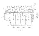
- FIG. 1 is a perspective view from above of an intake device according to an embodiment of the present invention.
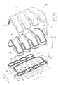
- 1 is a perspective view from below of an air intake device according to an embodiment of the present invention. It is the disassembled perspective view which showed the structure of the intake device by one Embodiment of this invention.
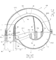
- FIG. 1 is a schematic longitudinal sectional view along an intake passage of an intake device according to an embodiment of the present invention. It is the top view which showed the lower surface side of the lower piece of the intake device by one Embodiment of this invention.
- A is a schematic longitudinal cross-sectional view of an air intake device according to a comparative example.
- B is a schematic longitudinal cross-sectional view of the air intake device according to one embodiment of the present invention.
- C is a typical longitudinal section of the intake device by the modification of one embodiment of the present invention.
- FIGS. 1 to 5 The configuration of an intake system 100 according to an embodiment of the present invention will be described with reference to FIGS. 1 to 5.
- an example of an intake system provided in an in-line four-cylinder engine (not shown) for a vehicle will be described.
- the intake system 100 includes a surge tank 1 (see FIG. 2) and four intake passages 2 branched from the surge tank 1 and disposed downstream of the surge tank 1. Have.
- the intake system 100 is configured to be connected to the cylinder head 90 so that the four intake passages 2 are respectively connected to each cylinder of the engine (internal combustion engine) via an intake port 91 (see FIG. 4). ing.
- the intake device 100 has a three-piece structure in which the intake device main body portion 101 includes an upper piece 3, a middle piece 4 and a lower piece 5.
- the upper piece 3, the middle piece 4 and the lower piece 5 are examples of the “first piece”, the “middle piece” and the “second piece” in the present invention respectively.
- the upper piece 3, the middle piece 4 and the lower piece 5 are formed of a resin material which can be bonded to each other.
- a resin material nylon 6 (PA 6) or the like can be used, for example.
- PA 6 nylon 6
- the upper piece 3, the middle piece 4 and the lower piece 5 are integrally joined to each other by vibration welding, whereby the intake device main body portion 101 is formed.
- the X direction in which the four intake passages 2 are arranged is the horizontal direction
- the middle piece 4 and the lower piece 5 is the vertical direction (Z1 on the upper piece 3 side
- the direction is referred to as the upper direction
- the Z2 direction on the lower piece 5 side is the lower direction
- the Y direction orthogonal to the X direction and the Z direction is the front-rear direction.
- the surge tank 1 includes a partition in the Y2 direction (partitions 41 and 52) and a partition in the Y1 direction (walls 42 and 53). , And the partition wall (wall portion 43) on the Z1 direction side.
- the partition 41 is an example of the "first partition” in the present invention.
- the wall 42 and the wall 43 are examples of the “first surge tank wall” and the “second surge tank wall” in the present invention respectively.
- the partition part 52 is an example of the "2nd partition" of this invention.
- each of the four intake passages 2 communicates with the surge tank 1 and includes an intake passage upstream portion 21 and an intake passage downstream portion 22.
- the intake passage upstream portion 21 communicates with the surge tank 1 at the upstream end portion (inlet portion) 21 a and is a passage portion that curves and extends from the lower portion of the surge tank 1 to the Y1 direction side. ing.
- the intake passage upstream portion 21 is partitioned by the wall portions 54 and 55 in a longitudinal cross section (YZ cross section) along the intake passage 2.
- the intake passage upstream portion 21 is an example of the “circularly extending cylindrical portion” in the present invention.
- the intake passage downstream portion 22 communicates with the intake passage upstream portion 21 at the upstream end, and extends above the surge tank 1 in the Y2 direction to surround the periphery of the surge tank 1 and reaches the downstream end portion 23 It is a passage part.
- a portion (a portion of the range L1) in the vicinity of the downstream end portion 23 (flange portion 51) of the intake passage downstream portion 22 extends in the vertical direction (Z direction) along the Y2 direction side surface of the surge tank 1.
- the intake passage downstream portion 22 includes the wall portions 31, 43, 45, 56, and a partition (partition portions 41 and 52) on the Y2 direction side of the surge tank 1. It is divided by.
- Each intake passage 2 extends to surround the periphery of the surge tank 1 by the intake passage upstream portion 21 and the intake passage downstream portion 22, and intake in the vicinity of a connection portion (flange portion 51) with the intake port 91.
- the passage downstream portion 22 is provided to extend along the side surface of the surge tank 1.
- the Y2 direction side surface of the surge tank 1 in the intake device main body portion 101 and the portion L1 and the downstream end portion 23 of the intake passage downstream portion 22 It is divided by one partition.
- the partition 41 and the wall 43 both define the surge tank 1 and the intake passage downstream portion 22.
- the upper piece 3 is provided so as to cover the upper (Z1 direction side) portion of the middle piece 4, and the intake passage downstream portion 22 of the four intake passages 2 aligned in the X direction.
- Upper piece 3 integrally includes a wall portion 31 which divides intake passage downstream portion 22 in a longitudinal cross section (YZ cross section) along intake passage 2 shown in FIG. 4.
- the upper piece 3 is joined to the middle piece 4 at the joining portion 32.
- the middle piece 4 constitutes the surge tank 1 and is joined to the upper piece 3 on the upper surface side and joined to the lower piece 5 on the lower surface side.
- the middle piece 4 is formed with an upper portion 11 corresponding to approximately 3 ⁇ 4 of the surge tank 1, and the middle piece 4 has a longitudinal cross section (YZ cross section along the intake passage 2).
- the wall portions 42 and 43 which define the upper portion 11 and the partition portion 41 described above are integrally included.
- the wall portion 42 is disposed on the side (the Y1 direction side) opposite to the partition portion 41 in the surge tank 1.
- the wall 43 connects the Z1 direction end of the partition 41 to the Z1 direction end of the wall 42.
- the middle piece 4 constitutes a substantially half of the lower side (Z2 direction side) of the intake passage downstream portion 22 of the intake passage 2.
- the upper piece 3 and the middle piece 4 constitute an intake passage downstream portion 22 communicating with the intake passage upstream portion 21 except for the downstream end portion 23 formed in the lower piece 5.
- the portion of the range L1 extending in the vertical direction (Z direction) along the Y2 direction side surface of the surge tank 1 and the upper portion 11 of the surge tank 1 do not separate from each other. It is arranged to be adjacent via a single partition 41. Further, on the lower end surface of the partition wall portion 41, a second bonding portion 44 to be bonded to a first bonding portion 58 described later of the lower piece 5 is provided.
- the partition portion 41 is formed to extend linearly in the Z direction from the second joint portion 44 in a longitudinal cross section (YZ cross section) along the intake passage 2 (the intake passage upstream portion 21 and the intake passage downstream portion 22) There is.
- the intake passage downstream portion 22 is divided by the partition 41 and the wall 45 (and the wall 31 of the upper piece 3) in the range L1. It is done.
- a joint 46 with the lower piece 5 is provided.
- the partition 41 of the middle piece 4 has a thickness t1 at the second bonding portion 44, and the thickness t1 is for bonding the second bonding portion 44 to the first bonding portion 58 of the lower piece 5. It has a sufficient thickness.
- the lower piece 5 integrally includes an intake passage upstream portion 21 communicating with the surge tank 1 and is joined to the lower surface of the middle piece 4 on the upper surface side.
- the lower piece 12 is provided with the lower portion 12 corresponding to about 1 ⁇ 4 of the surge tank 1 and the intake passage upstream portion 21 having a substantially arc cylindrical shape. The whole of is formed.
- the lower end portion 23 of the intake passage downstream portion 22 having the flange portion 51 connecting the intake passage downstream portion 22 and the intake port 91 is integrally formed on the lower piece 5.
- lower piece 5 integrally has a wall portion 53 and a partition portion 52 which divides lower portion 12 constituting surge tank 1 in a longitudinal cross section (YZ cross section) along intake passage 2 shown in FIG. 4. It contains. Lower piece 5 also includes wall portions 54 and 55 that define intake passage upstream portion 21. Lower piece 5 also includes a wall 56 that defines downstream end portion 23 together with partition 52.
- the intake passage upstream portion 21 of the lower piece 5 is formed of a cylindrical portion extending in an arc shape along the intake passage 2, and the flow passage width is gradually increased from the downstream side toward the upstream side (FIG.
- the gap between the wall 54 and the wall 55 in the longitudinal cross section of the passage 2 is formed to be large.
- the intake passage upstream portion 21 of the lower piece 5 has a single piece cylindrical intake passage shape by using the rotary slide mold core C (see the two-dot chain line in FIG. 4). It is possible to form That is, after the wall portion (wall portion 54 and wall portion 55) is formed in a cylindrical shape around the mold core C corresponding to the intake passage upstream portion 21, the lower piece 5 is relative to the mold core C in the A direction.
- the shape in which the flow passage width of the intake passage upstream portion 21 increases toward the upstream side also functions as a draft of the mold core C.
- the lower piece 5 is joined to the upstream end of the intake passage downstream portion 22 of the middle piece 4 at joints 57 a and 57 b of the downstream end of the intake passage upstream portion 21.
- the flange portion 51 protrudes outward (mainly in the X direction) including the partition wall 52 and the wall 56 at the outer peripheral portion of the downstream end portion 23 of the intake passage downstream portion 22. It is provided as. Specifically, the flange portion 51 is formed so as to connect the respective downstream end portions 23 of the four intake passages 2 in the X direction and to project further outward in the X direction at both end portions in the X direction. . A plurality of holes 51a for connecting with the cylinder head of the engine are formed at positions between the intake passages 2 (the downstream end portions 23) and at both ends of the flange 51 in the X direction. There is.
- the intake device 100 is connected (fastened) to the engine side by inserting a collar and a fastening member (not shown) into the hole 51a.
- the flange portion 51 is adjacent to the upstream side end portion of the cylindrical intake passage upstream portion 21 extending in an arc shape in a longitudinal cross section (YZ cross section) along the intake passage 2 shown in FIG. It is formed as.
- the flange portion 51 (the downstream end portion 23) of the lower piece 5 and the wall portion on the flange portion 51 side (the Y2 direction side) of the lower portion 12 of the surge tank 1 are adjacent and integrated. It has been That is, the flange portion 51 (the downstream end portion 23) and the lower portion 12 of the surge tank 1 are partitioned by the common partition portion 52 without being separated in the Y direction.
- the flange portion 51 is provided so as to connect the plurality of intake passage downstream portions 22 to each other, and is adjacent to and integrated with the wall portion on the flange portion 51 side of the surge tank 1.
- the lower piece 5 is provided with a first joint portion 58 joined to the middle piece 4 on the upper surface of the partition wall 52.
- the joint line of the wall portion constituting flange portion 51 and lower portion 12 of surge tank 1 is formed continuously without interruption. It is done.
- a portion disposed in the partition 52 between the flange 51 and the lower portion 12 is a first joint 58.
- the thickness t1 of the second bonding portion 44 and the thickness t2 of the first bonding portion 58 are substantially equal to each other.
- the thickness t2 is sufficient to join the first joint portion 58 with the second joint portion 44 of the middle piece 4.
- the lower piece 5 performs the second bonding of the middle piece 4 at the first bonding portion 58 of the partition 52 and the bonding portion 57c of the upper end surface of the wall 56.
- the surge tank 1 including the
- reinforcement ribs 59 are provided in portions between the flange portion 51 and the lower portion 12 of the surge tank 1 and the intake passage upstream portion 21. Is provided.
- the reinforcing rib 59 has an outer surface on the surge tank 1 (lower portion 12) side (Y1 direction side) of the flange portion 51, and a wall on the flange portion 51 side (Y2 direction side) of the lower portion 12 and the intake passage upstream portion 21.
- the lower piece 5 is integrally formed so as to connect with the outer surface of the part. That is, as shown in FIG.
- the reinforcing rib 59 is formed to extend not only to the outer surface of the lower portion 12 of the lower piece 5 but also to the outer surface of the wall 55 of the intake passage upstream portion 21. Further, the reinforcing rib 59 is formed to extend in the tangential direction toward the outer surface of the wall portion of the intake passage upstream portion 21 from the end portion of the flange portion 51 on the surge tank 1 side. More specifically, the reinforcing rib 59 extends over a wide range of the length L2 from the lower end portion of the flange portion 51 in the Y2 direction to the intersection point of the tangent drawn to the wall portion 55 of the intake passage upstream portion 21. It is formed. Further, as shown in FIG.
- a plurality of reinforcing ribs 59 are provided so as to connect the flange portion 51 and the respective wall portions of the plurality of intake passage upstream portions 21.
- four reinforcing ribs 59 are formed for each intake passage 2 in total.
- Each reinforcing rib 59 is formed at the central portion of each intake passage 2 in the X direction, and has a plate-like shape with a thickness t3.
- FIG. 6A shows, as a comparative example, an intake device S in which a flange portion is provided on the middle piece and the surge tank and the flange portion are separated in the Y direction with a space D1.
- the conventional configuration is adopted only at the point that the flange portion is provided on the middle piece and the surge tank and the flange portion are separated in the Y direction.
- This is a virtual configuration example configured to be closer to the intake device 100 of
- FIG. 6 (B) shows the intake device 100 of the present embodiment shown in FIGS.
- an intake device 200 is configured in which the device dimensions (dimensions in the Y direction) of the intake device 100 of the present embodiment match the intake device S of the comparative example. It shows.
- the flange portion 51s is formed in the middle piece 4s, and the lower piece 5s includes the intake passage upstream portion 21s and the lower portion of the surge tank 1s. Contains only That is, the lower end portion that constitutes a part of the intake passage downstream portion 22s of the intake passage 2s is not formed in the lower piece 5s. Therefore, the lower piece 5s is joined to the middle piece 4s by vibration welding at the side wall 47s of the surge tank 1s.
- the middle piece 4s and the lower piece 5s are moved (slided) relative to each other on the side wall 47s to perform vibration welding, so that a space D (relative movement) for vibration welding is provided for the distance D1.
- the intake system S is configured such that the bending radius R1 of the intake passage upstream portion 21s is substantially equal to the bending radius R1 of the intake passage upstream portion 21 of the intake device 100 of the present embodiment shown in FIG. An example is shown. Note that the bending radius shown here is the radius of the arc shown generally along the passage center line of the intake passage, and as described above, the channel width is not constant, so An arc) is shown as the radius of the arc.
- a single partition (partitions 41 and 52) is provided between the intake passage downstream portion 22 including the flange 51 and the surge tank 1.
- the lower piece 5 is joined to the middle piece 4 at the first joint portion 58 and the joint portions 57a, 57b, 57c and 57d when viewed in a longitudinal cross section (YZ cross section) along the intake passage 2. In this case, it is not necessary to secure a space for vibration welding inside the intake device 100.
- the surge tank 1 and the intake passage upstream portion 21 can be disposed for the total distance D2 of the thickness t4 of the side wall 47s and the interval D1 compared to the intake system S. It is possible to secure an internal space.
- the size of the intake device 100 is made compact by the length L3 in the Y direction.
- the side wall of the intake device 200 according to the modification of the present embodiment in which the entire length in the Y direction of the device matches the intake device S of the comparative example. It is possible to secure an internal space in which the surge tank 101 and the intake passage upstream portion 121 can be disposed by the total distance D2 of the thickness t4 of 47 s and the interval D1.
- the intake passage upstream portion 121 is configured with a bending radius R2 larger than the radius R1.
- the intake passage upstream portion 121 is an example of the “circularly extending cylindrical portion” in the present invention.
- the intake device S of the comparative example is structurally located in a portion S1 on the Y2 direction side of the surge tank 1s in the intake passage downstream portion 22s, the surge tank 1s and the intake passage upstream.
- a portion S2 on the Y1 direction side in which the portion 21s is disposed is separated from the space D1. Therefore, when the intake device S is attached to the engine side by the flange portion 51s that is a connection portion with the cylinder head, the Y2 direction side portion S1 of the intake device S is the Y1 direction side portion (surge tank 1s and the intake passage upstream portion) 21s) It has a structure to support S2.
- the Y1 direction side portion S2 which is a weight portion, is supported at the tip of the cantilever Y2 direction side portion S1.
- the intake system S it becomes difficult to suppress the vibration of the Y1 direction side portion S2.
- the Y2 direction side portion (the intake passage downstream portion 22) and the Y1 direction side portion (the surge tank 1 and the intake passage upstream portion 21) There is no gap between them, and the flange portion 51 which is the connection portion and the Y1 direction side portion (the surge tank 1 and the intake passage upstream portion 21) are integrally connected in the lower piece 5 by the partition 52 at the shortest distance. .
- the rigidity of the entire intake system 100 is improved as compared with the intake system S of the comparative example, and the vibration in the Y1 direction side portion which is the weight portion is suppressed. Is possible. This point is the same as that of the intake device 200 of the modification shown in FIG. 6 (C).
- the lower piece 5 is provided with the flange portion 51 connecting the intake passage downstream portion 22 and the intake port 91 to the vicinity of the intake passage upstream portion 22 communicating with the surge tank 1 in the lower piece 5.
- Side wall of the lower portion 12 and the side wall of the flange portion 51 by a joint surface (first joint portion 58) with the middle piece 4 to form a single side wall (partition wall portion 52) Can. Therefore, also on the middle piece 4 side joined to the lower piece 5, the side wall of the surge tank 1 (upper portion 11) and the side wall of the intake passage downstream portion 22 are connected to form a single side wall (partition 41). Thus, it can be joined to a single side wall (partition 52) of the lower piece 5.
- the intake device 100 can be miniaturized. Further, in the present embodiment, by providing the flange portion 51 on the lower piece 5, the vibration transmitting portion (flange portion 51) and the weight portion (surge tank 1 side portion) of the intake device 100 are connected at a short distance in the lower piece 5. Therefore, the vibration of the entire intake device 100 can be suppressed.
- the degree of freedom in design for meeting the required specifications can be increased without increasing the size of the device. Is possible. As a result of these, it is possible to increase the degree of freedom of design when mounting the intake system 100 (200) in a limited space, and therefore it is possible to improve the mountability (easiness of mounting) of the intake system. .
- the flange portion 51 of the lower piece 5 and the wall portion on the flange portion 51 side of the surge tank 1 of the lower piece 5 are adjacently integrated by the partition portion 52. Then, a first joint portion 58 joined to the middle piece 4 is provided in the partition portion 52.
- the flange portion 51 and the lower portion 12 of the surge tank 1 can be integrated without being separated, the size can be reduced accordingly.
- the flange portion 51 which is a connecting portion with the intake port 91 is integrated with the surge tank 1 (lower portion 12) in the lower piece 5, the rigidity of the entire intake device 100 can be improved. Vibration of the intake system 100 at the time of driving the engine can also be suppressed.
- the surge tank 1 (upper portion 11) of the middle piece 4 and the intake passage downstream portion 22 of the middle piece 4 are adjacent via the single partition portion 41.
- the partition wall portion 41 is provided with a second joint portion 44 joined to the first joint portion 58 of the lower piece 5.
- the surge tank 1 and the intake passage downstream portion 22 can be integrated by the single (common) partition portion 41.
- the partition 41 and the wall 43 are both provided to separate the surge tank 1 and the intake passage downstream portion 22.
- the surge tank 1 and the intake passage downstream portion 22 can be integrated by the common partition wall in a wider range of the partition wall portion 41 and the wall portion 43.
- the intake device 100 can be further miniaturized, and the rigidity of the entire intake device 100 can be easily improved.
- the partition portion 41 is linearly extended from the second joint portion 44. Form. Thereby, since the shape of the partition part 41 can be simplified, when forming the middle piece 4, the partition part 41 and the 2nd junction part 44 can be formed easily.
- the thickness t1 of the second bonding portion 44 and the thickness t2 of the first bonding portion 58 are equal to each other. Therefore, if the thickness of the second joint portion 44 and the first joint portion 58 is sufficiently secured to join each other, a common partition wall having the minimum necessary thickness for the intake passage downstream portion 22 and the surge tank 1 It can be integrated through (partitions 41 and 52). As a result, it is not necessary to increase the thickness of the partition wall more than necessary.
- a plurality of intake passage upstream portions 21 and a plurality of intake passage downstream portions 22 are provided.
- the flange portion 51 is provided to connect the plurality of intake passage downstream portions 22 with each other, and the wall portion on the flange portion 51 side of the surge tank 1 (lower portion 12) and the flange portion 51 are adjacent to each other. Integrate. As a result, it is not necessary to integrate each of the plurality of intake passage upstream portions 21 with the flange portion 51, and only the flange portion 51 and the surge tank 1 may be integrated, so the structure of the lower piece 5 is simplified. be able to.
- the downstream end portion 23 of the intake passage downstream portion 22 provided with the flange portion 51 is adjacent to the surge tank 1 (lower portion 12) to be a common partition wall portion Divide by 52.
- the surge tank 1 and the intake passage downstream portion 22 can be adjacent via the common partition 52.
- the overall size of the intake system 100 can be reduced, and the rigidity of the intake system 100 can be improved.
- the flange portion 51s of the middle piece 4s and the lower piece 5s are separate pieces. It becomes impossible to form a reinforcement rib.
- the flange portion 51, the surge tank 1 (lower portion 12), and the intake passage upstream portion 21 are formed in the same lower piece 5. Since it is formed, the rigidity of the intake device 100 can be easily improved with a simple configuration in which only the reinforcing rib 59 is provided.
- the reinforcing rib 59 is formed to extend over the range of the length L2 to the outer surface of the wall 55 corresponding to the upstream portion 21 of the intake passage of the lower piece 5. .
- the reinforcing rib 59 can be provided in a wide range from the surge tank 1 to the intake passage upstream portion 21, the rigidity of the intake device 100 can be more effectively improved.
- the reinforcing rib 59 is formed so as to extend in the tangential direction toward the outer surface of the wall portion of the intake passage upstream portion 21 from the end of the flange portion 51 on the surge tank 1 side.
- a plurality of reinforcing ribs 59 are provided so as to connect the flange portion 51 and the respective wall portions of the plurality of intake passage upstream portions 21.
- the rigidity can be improved by the reinforcing rib 59 for each of the individual intake passage upstream portions 21.
- the intake passage upstream portion 21 of the lower piece 5 is formed in a cylindrical shape extending in an arc along the intake passage, and the flange portion 51 is a cylindrical shape extending in an arc. It is formed to be adjacent to the upstream portion 21 of the intake passage.
- the lower piece 5 in which the cylindrical portion (intake passage upstream portion 21) extending in an arc shape is formed can be formed as a single piece by using the rotary slide type mold core C.
- the flange portion 51 provided on the lower piece 5 is rotated relative to the mold core C in the A direction (see FIG. 4) with respect to the process of extracting the lower piece 5 and the mold core C (see FIG. 4). Since it can utilize also as an engaging part in the process of extracting from, it is not necessary to separately provide an engaging part for extraction on the outer surface of the lower piece 5.
- the intake passage upstream portion 21 is formed such that the flow passage width increases from the downstream side toward the upstream side. As a result, a draft at the time of removing the molded product (cylindrical part) from the mold core can be formed in the intake passage upstream portion 21. As a result, the lower piece 5 can be formed more easily.
- the upper piece 3, the middle piece 4 and the lower piece 5 are formed of a resin that can be bonded to each other.
- upper piece 3, middle piece 4 and lower piece 5 can be easily joined by vibration welding.
- the intake system of this invention may be applied to an intake system for an internal combustion engine other than an automobile engine, or to an intake system for an automobile engine other than an in-line four-cylinder engine.
- the intake system may be configured with four or more pieces.
- the example which provided a part (lower part) of a surge tank and the intake passage upstream part in the lower piece in the said embodiment was shown, this invention is not limited to this.
- the lower piece may be provided with only the upstream portion of the intake passage without forming the lower portion of the surge tank.
- the intake passage upstream portion and the flange portion 51 (downstream end portion) may be configured to be partitioned by a single partition portion.
- the reinforcing rib is provided in the range (see FIG. 4) of the length L2 between the flange portion of the lower piece and the surge tank (lower portion) and the intake passage upstream portion.
- the present invention is not limited to this.
- the reinforcing rib may be provided in a range shorter than the length L2.
- the reinforcing rib may be provided only at a portion between the flange portion and the surge tank (lower portion) without extending to the intake passage upstream portion.
- the intake passage upstream portion of the lower piece is formed in a cylindrical shape extending in an arc shape, and can be formed in a single piece using a rotary slide type mold core.
- the lower piece may be divided into upper and lower parts to form an upper lower piece and a lower lower piece with a normal mold, and then the upper lower piece and the lower lower piece may be joined to form the lower piece. In this case, in FIG.
- the middle portion in the vertical direction of the intake passage upstream portion 21 may be divided into two, and the flange portion 51 (downstream end portion 23), the lower portion 12 of the surge tank 1, and the intake passage upstream portion
- the lower piece 5 can be configured by joining the upper lower piece including the upper portion of the upper portion 21 and the lower lower piece including the lower portion of the intake passage upstream portion 21.
- the upper piece, the middle piece, and the lower piece with the resin material which can mutually be joined was shown in the said embodiment, this invention is not limited to this.
- the upper piece, the middle piece, and the lower piece may be made of a material other than a resin material.
Landscapes
- Engineering & Computer Science (AREA)
- Chemical & Material Sciences (AREA)
- Combustion & Propulsion (AREA)
- Mechanical Engineering (AREA)
- General Engineering & Computer Science (AREA)
- Manufacturing & Machinery (AREA)
- Characterised By The Charging Evacuation (AREA)
Priority Applications (3)
| Application Number | Priority Date | Filing Date | Title |
|---|---|---|---|
| CN201490000763.XU CN205207017U (zh) | 2013-05-29 | 2014-03-11 | 进气装置 |
| EP14803709.6A EP2975254B1 (en) | 2013-05-29 | 2014-03-11 | Intake system |
| US14/782,941 US9850862B2 (en) | 2013-05-29 | 2014-03-11 | Air intake apparatus |
Applications Claiming Priority (2)
| Application Number | Priority Date | Filing Date | Title |
|---|---|---|---|
| JP2013112533A JP6160248B2 (ja) | 2013-05-29 | 2013-05-29 | 吸気装置 |
| JP2013-112533 | 2013-05-29 |
Publications (1)
| Publication Number | Publication Date |
|---|---|
| WO2014192359A1 true WO2014192359A1 (ja) | 2014-12-04 |
Family
ID=51988403
Family Applications (1)
| Application Number | Title | Priority Date | Filing Date |
|---|---|---|---|
| PCT/JP2014/056354 Ceased WO2014192359A1 (ja) | 2013-05-29 | 2014-03-11 | 吸気装置 |
Country Status (5)
| Country | Link |
|---|---|
| US (1) | US9850862B2 (https=) |
| EP (1) | EP2975254B1 (https=) |
| JP (1) | JP6160248B2 (https=) |
| CN (1) | CN205207017U (https=) |
| WO (1) | WO2014192359A1 (https=) |
Cited By (1)
| Publication number | Priority date | Publication date | Assignee | Title |
|---|---|---|---|---|
| JP2020183718A (ja) * | 2019-05-07 | 2020-11-12 | トヨタ紡織株式会社 | 車載内燃機関の吸気マニホールド |
Families Citing this family (4)
| Publication number | Priority date | Publication date | Assignee | Title |
|---|---|---|---|---|
| DE102017210833A1 (de) * | 2017-06-27 | 2018-12-27 | Ford Global Technologies, Llc | Hubkolbenbrennkraftmaschine und Kraftfahrzeug |
| JP7024406B2 (ja) * | 2017-12-29 | 2022-02-24 | トヨタ紡織株式会社 | 吸気マニホールド |
| US10808657B2 (en) * | 2018-02-02 | 2020-10-20 | Ford Global Technologies, Llc | Vehicle component with an accessory mounting feature and a method and tool for forming |
| JP7493230B2 (ja) * | 2020-09-26 | 2024-05-31 | 株式会社ミクニ | 吸気マニホールド及び船外機 |
Citations (4)
| Publication number | Priority date | Publication date | Assignee | Title |
|---|---|---|---|---|
| JPH10339224A (ja) * | 1997-06-09 | 1998-12-22 | Inoac Corp | 内燃機関用合成樹脂製吸気マニホールド |
| JP2006057509A (ja) * | 2004-08-19 | 2006-03-02 | Gp Daikyo Corp | 多気筒エンジンの樹脂製吸気マニホールド |
| JP2010285916A (ja) * | 2009-06-10 | 2010-12-24 | Mazda Motor Corp | エンジンの吸気装置 |
| JP2012251518A (ja) | 2011-06-06 | 2012-12-20 | Aisan Industry Co Ltd | 樹脂製インテークマニホールド、樹脂製インテークマニホールドの製造方法 |
Family Cites Families (9)
| Publication number | Priority date | Publication date | Assignee | Title |
|---|---|---|---|---|
| US5636605A (en) * | 1994-06-22 | 1997-06-10 | Toyota Jidosha K.K. | Composite intake manifold for an internal combustion engine |
| JP3542322B2 (ja) | 2000-08-30 | 2004-07-14 | 東洋▲ろ▼機製造株式会社 | 湾曲管部を有する樹脂成形品用の金型 |
| DE10045636B4 (de) * | 2000-09-15 | 2012-04-12 | Audi Ag | Vorrichtung zum Führen eines sekundären Gases |
| JP2004204792A (ja) * | 2002-12-26 | 2004-07-22 | Aisan Ind Co Ltd | 内燃機関の吸気装置 |
| JP4422557B2 (ja) | 2004-06-10 | 2010-02-24 | トヨタ自動車株式会社 | インテークマニホールド |
| JP4625379B2 (ja) * | 2005-07-04 | 2011-02-02 | 株式会社ケーヒン | エンジン用吸気制御装置 |
| EP1748167B1 (en) | 2005-07-04 | 2014-03-26 | Keihin Corporation | Engine intake control device |
| JP4280755B2 (ja) | 2006-05-16 | 2009-06-17 | アイティテクノ 株式会社 | 円弧筒状部を有する成形品の成形型、及び該成形品を成形型から抜取る方法 |
| JP5027014B2 (ja) | 2008-03-04 | 2012-09-19 | 愛三工業株式会社 | 樹脂製インテークマニホールド |
-
2013
- 2013-05-29 JP JP2013112533A patent/JP6160248B2/ja active Active
-
2014
- 2014-03-11 EP EP14803709.6A patent/EP2975254B1/en active Active
- 2014-03-11 US US14/782,941 patent/US9850862B2/en active Active
- 2014-03-11 CN CN201490000763.XU patent/CN205207017U/zh not_active Expired - Lifetime
- 2014-03-11 WO PCT/JP2014/056354 patent/WO2014192359A1/ja not_active Ceased
Patent Citations (4)
| Publication number | Priority date | Publication date | Assignee | Title |
|---|---|---|---|---|
| JPH10339224A (ja) * | 1997-06-09 | 1998-12-22 | Inoac Corp | 内燃機関用合成樹脂製吸気マニホールド |
| JP2006057509A (ja) * | 2004-08-19 | 2006-03-02 | Gp Daikyo Corp | 多気筒エンジンの樹脂製吸気マニホールド |
| JP2010285916A (ja) * | 2009-06-10 | 2010-12-24 | Mazda Motor Corp | エンジンの吸気装置 |
| JP2012251518A (ja) | 2011-06-06 | 2012-12-20 | Aisan Industry Co Ltd | 樹脂製インテークマニホールド、樹脂製インテークマニホールドの製造方法 |
Cited By (2)
| Publication number | Priority date | Publication date | Assignee | Title |
|---|---|---|---|---|
| JP2020183718A (ja) * | 2019-05-07 | 2020-11-12 | トヨタ紡織株式会社 | 車載内燃機関の吸気マニホールド |
| JP7234782B2 (ja) | 2019-05-07 | 2023-03-08 | トヨタ紡織株式会社 | 車載内燃機関の吸気マニホールド |
Also Published As
| Publication number | Publication date |
|---|---|
| US20160061167A1 (en) | 2016-03-03 |
| EP2975254A1 (en) | 2016-01-20 |
| JP2014231771A (ja) | 2014-12-11 |
| EP2975254A4 (en) | 2016-05-11 |
| CN205207017U (zh) | 2016-05-04 |
| JP6160248B2 (ja) | 2017-07-12 |
| US9850862B2 (en) | 2017-12-26 |
| EP2975254B1 (en) | 2018-05-02 |
Similar Documents
| Publication | Publication Date | Title |
|---|---|---|
| WO2014192359A1 (ja) | 吸気装置 | |
| US8176889B2 (en) | Intake manifold for engine | |
| JP6600236B2 (ja) | 車両用エアダクト | |
| JP4968096B2 (ja) | 車両用内燃機関の吸気装置 | |
| KR20170112867A (ko) | 차량용 소음저감 장치 | |
| JP2006017090A (ja) | エンジン | |
| WO2016143199A1 (ja) | 自動二輪車のエアクリーナ装置 | |
| US8695754B2 (en) | Muffler of internal combustion engine | |
| JP2013053582A (ja) | 樹脂製インテークマニホールド | |
| JP6639215B2 (ja) | 吸気マニホルド | |
| JP2014231771A5 (https=) | ||
| KR101129918B1 (ko) | 다기통 내연기관의 흡기 매니폴드 | |
| JP5980139B2 (ja) | 車両用消音器 | |
| JP4853423B2 (ja) | 空調用ダクトの製造方法 | |
| JP6013090B2 (ja) | 樹脂製インテークマニホールド | |
| JP2017186942A (ja) | エアクリーナ | |
| JP2009281333A (ja) | 排気マニホールド | |
| JP2017172514A (ja) | インテークマニホールド | |
| JP4507687B2 (ja) | インテークマニホールド | |
| KR101171574B1 (ko) | 자동 이륜차의 에어 클리너 구조 | |
| JP2019023447A (ja) | エンジンの排気装置 | |
| JP5821785B2 (ja) | 吸気ダクト | |
| JP2012207650A (ja) | 内燃機関用吸気マニホールド | |
| KR101699335B1 (ko) | 플라스틱 흡기 매니폴드 조립 구조 | |
| JP2011094633A (ja) | レゾネータを備える多気筒内燃機関 |
Legal Events
| Date | Code | Title | Description |
|---|---|---|---|
| 121 | Ep: the epo has been informed by wipo that ep was designated in this application |
Ref document number: 14803709 Country of ref document: EP Kind code of ref document: A1 |
|
| WWE | Wipo information: entry into national phase |
Ref document number: 14782941 Country of ref document: US |
|
| WWE | Wipo information: entry into national phase |
Ref document number: 2014803709 Country of ref document: EP |
|
| NENP | Non-entry into the national phase |
Ref country code: DE |