WO2014192359A1 - Intake system - Google Patents
Intake system Download PDFInfo
- Publication number
- WO2014192359A1 WO2014192359A1 PCT/JP2014/056354 JP2014056354W WO2014192359A1 WO 2014192359 A1 WO2014192359 A1 WO 2014192359A1 JP 2014056354 W JP2014056354 W JP 2014056354W WO 2014192359 A1 WO2014192359 A1 WO 2014192359A1
- Authority
- WO
- WIPO (PCT)
- Prior art keywords
- piece
- intake passage
- surge tank
- intake
- wall
- Prior art date
Links
Images


Classifications
-
- F—MECHANICAL ENGINEERING; LIGHTING; HEATING; WEAPONS; BLASTING
- F02—COMBUSTION ENGINES; HOT-GAS OR COMBUSTION-PRODUCT ENGINE PLANTS
- F02M—SUPPLYING COMBUSTION ENGINES IN GENERAL WITH COMBUSTIBLE MIXTURES OR CONSTITUENTS THEREOF
- F02M35/00—Combustion-air cleaners, air intakes, intake silencers, or induction systems specially adapted for, or arranged on, internal-combustion engines
- F02M35/10—Air intakes; Induction systems
- F02M35/1034—Manufacturing and assembling intake systems
- F02M35/10354—Joining multiple sections together
-
- F—MECHANICAL ENGINEERING; LIGHTING; HEATING; WEAPONS; BLASTING
- F02—COMBUSTION ENGINES; HOT-GAS OR COMBUSTION-PRODUCT ENGINE PLANTS
- F02M—SUPPLYING COMBUSTION ENGINES IN GENERAL WITH COMBUSTIBLE MIXTURES OR CONSTITUENTS THEREOF
- F02M35/00—Combustion-air cleaners, air intakes, intake silencers, or induction systems specially adapted for, or arranged on, internal-combustion engines
- F02M35/10—Air intakes; Induction systems
- F02M35/10006—Air intakes; Induction systems characterised by the position of elements of the air intake system in direction of the air intake flow, i.e. between ambient air inlet and supply to the combustion chamber
- F02M35/10026—Plenum chambers
- F02M35/10039—Intake ducts situated partly within or on the plenum chamber housing
-
- F—MECHANICAL ENGINEERING; LIGHTING; HEATING; WEAPONS; BLASTING
- F02—COMBUSTION ENGINES; HOT-GAS OR COMBUSTION-PRODUCT ENGINE PLANTS
- F02M—SUPPLYING COMBUSTION ENGINES IN GENERAL WITH COMBUSTIBLE MIXTURES OR CONSTITUENTS THEREOF
- F02M35/00—Combustion-air cleaners, air intakes, intake silencers, or induction systems specially adapted for, or arranged on, internal-combustion engines
- F02M35/10—Air intakes; Induction systems
- F02M35/10091—Air intakes; Induction systems characterised by details of intake ducts: shapes; connections; arrangements
- F02M35/10144—Connections of intake ducts to each other or to another device
-
- F—MECHANICAL ENGINEERING; LIGHTING; HEATING; WEAPONS; BLASTING
- F02—COMBUSTION ENGINES; HOT-GAS OR COMBUSTION-PRODUCT ENGINE PLANTS
- F02M—SUPPLYING COMBUSTION ENGINES IN GENERAL WITH COMBUSTIBLE MIXTURES OR CONSTITUENTS THEREOF
- F02M35/00—Combustion-air cleaners, air intakes, intake silencers, or induction systems specially adapted for, or arranged on, internal-combustion engines
- F02M35/10—Air intakes; Induction systems
- F02M35/104—Intake manifolds
- F02M35/112—Intake manifolds for engines with cylinders all in one line
-
- F—MECHANICAL ENGINEERING; LIGHTING; HEATING; WEAPONS; BLASTING
- F02—COMBUSTION ENGINES; HOT-GAS OR COMBUSTION-PRODUCT ENGINE PLANTS
- F02M—SUPPLYING COMBUSTION ENGINES IN GENERAL WITH COMBUSTIBLE MIXTURES OR CONSTITUENTS THEREOF
- F02M35/00—Combustion-air cleaners, air intakes, intake silencers, or induction systems specially adapted for, or arranged on, internal-combustion engines
- F02M35/10—Air intakes; Induction systems
- F02M35/1034—Manufacturing and assembling intake systems
- F02M35/10347—Moulding, casting or the like
Definitions
- the present invention relates to an intake system.
- an intake system in which a surge tank and an intake passage are configured by a plurality of pieces.
- Such an intake device is disclosed, for example, in Japanese Unexamined Patent Publication No. 2012-251518.
- JP 2012-251518 A there is disclosed a three-piece intake system of an upper piece positioned at the upper side, a middle piece positioned at the middle, and a lower piece positioned at the lower side.
- the upper piece and the middle piece constitute the downstream portion of the intake passage
- the middle piece and the lower piece constitute the upstream portion of the surge tank and the intake passage.
- the intake passage communicates with the surge tank on the upstream side, and is connected to the intake port of the engine at a flange portion provided at the end of the downstream portion.
- the flange portion is integrally formed with the middle piece.
- the pieces of the intake system are made of resin and joined to each other by vibration welding. That is, the side wall of the surge tank is configured by vibration-welding the lower end surface (welding line) of the upper side wall portion of the middle piece and the upper end surface (welding line) of the lower side wall portion of the lower piece.
- the intake passage of the middle piece provided with the side wall of the surge tank constituted by the upper side wall portion of the middle piece and the lower side wall portion of the lower piece and the flange portion
- the side walls of the downstream portion are formed to be separated from each other and for bonding.
- the flange portion which is the connection portion with the intake port of the internal combustion engine is spaced apart from the side wall of the middle tank surge tank. Since it is provided, a structure susceptible to vibration in which a vibration transmitting portion (flange portion) at the time of operation of the internal combustion engine and a heavy portion (surge tank side portion) of the intake system are connected at a long distance As a result, it is difficult to suppress the vibration of the intake system.
- the present invention has been made to solve the problems as described above, and one object of the present invention is to provide an air intake device capable of achieving downsizing and suppressing vibration.
- an intake system includes a first piece, a surge tank, an intermediate piece joined to the first piece, and an upstream portion of an intake passage communicating with the surge tank. And a second piece joined to the middle piece, wherein the first piece and the middle piece constitute an intake passage downstream portion in communication with the intake passage upstream portion, and the second piece is further downstream of the intake passage And a flange portion connecting the portion and the intake port of the internal combustion engine.
- the second piece joined to the intermediate piece includes the intake passage upstream portion in communication with the surge tank, the intake passage downstream portion and the intake port of the internal combustion engine
- the side wall near the upstream portion of the intake passage communicating with the surge tank and the side wall of the flange portion are connected at least in the joint surface with the intermediate piece in the second piece. It can be a side wall. Therefore, also on the intermediate piece side joined to the second piece, the side wall of the surge tank and the side wall of the intake passage downstream portion are connected to form a single side wall and joined to the single side wall of the second piece be able to.
- the vibration transmission portion (flange portion) and the weight portion (surge tank side portion) of the intake device are connected at a short distance in the second piece. As a result, the vibration of the entire intake system can be suppressed.
- the flange portion of the second piece and the wall portion on the flange portion side of the surge tank of the second piece or the upstream portion of the intake passage are adjacently integrated.
- a first joint is provided which is joined to the intermediate piece in the adjacent and integral part.
- the surge tank of the intermediate piece and the downstream portion of the intake passage of the intermediate piece are disposed adjacent to each other via a single first partition, and the first partition is the second piece And a second joint joined with the first joint.
- the surge tank and the downstream portion of the intake passage can be integrated by the single (common) first partition wall not only on the second piece but also on the intermediate piece side.
- the downstream portion of the intake passage and the surge tank can be integrated via a single (common) partition in a wide range of the side surface of the flange portion side (the downstream side of the intake passage) of the surge tank.
- the intake device can be easily miniaturized, and the mountability of the intake device can be easily improved.
- the first partition wall between the surge tank of the intermediate piece and the downstream portion of the intake passage adjacent to each other is integrated, so that the rigidity of the entire intake device can be easily improved.
- the surge tank includes the first partition, a first surge tank wall opposite to the first partition, and A second surge tank wall connecting the end of the first partition and the end of the first surge tank wall, wherein both the first partition and the second surge tank wall are connected to the surge tank and the intake passage downstream; And partition.
- the surge tank and the downstream portion of the intake passage can be integrated by the common partition in a wider range of the first partition and the second surge tank wall.
- the intake device can be further miniaturized, and the rigidity of the entire intake device can be easily improved.
- the first partition is a longitudinal cross section along the intake passage upstream portion and the intake passage downstream portion, It is formed to extend linearly from the second joint. According to this structure, since the shape of the first partition can be simplified, the first partition and the second joint can be easily formed, for example, when the intermediate piece is formed by resin molding.
- the thickness of the second joint and the thickness of the first joint are equal to each other.
- a common partition wall having a minimum necessary thickness for the downstream portion of the intake passage and the surge tank can be integrated. As a result, it is not necessary to increase the thickness of the partition wall more than necessary.
- a plurality of intake passage upstream portions and a plurality of intake passage downstream portions are provided.
- the flange portion is provided to connect each of the plurality of intake passage downstream portions to each other, and is integrated adjacent to the flange portion side wall portion of the surge tank.
- the downstream end portion of the intake passage downstream portion provided with the flange portion and the surge tank are partitioned adjacently by the common second partition wall.
- the surge tank and the intake passage downstream portion are common via the second partition wall. Can be adjacent to each other. As a result, the overall size of the intake system can be reduced, and the rigidity of the intake system can be improved.
- the second piece is provided to connect the outer surface of the flange portion on the surge tank side and the outer surface of the surge tank or the wall portion on the flange portion upstream side of the intake passage. Containing reinforced ribs. According to this structure, it is possible to reinforce between the flange portion, which is a connection portion with the intake port of the internal combustion engine, and the surge tank or the upstream portion of the intake passage, thereby further improving the rigidity of the intake device. As a result, vibration of the entire intake system can be further suppressed.
- the flange portion and the surge tank of the lower piece or the upstream portion of the intake passage are separate pieces and the reinforcing rib is integrally formed. Can not do it.
- the flange portion and the second piece side portion of the surge tank or the upstream portion of the intake passage are formed in the same second piece, the simple structure only having the reinforcing rib is provided. The rigidity of the intake system can be easily improved.
- the reinforcing rib is formed to extend not only to the portion corresponding to the surge tank of the second piece but also to the outer surface of the wall portion corresponding to the upstream portion of the intake passage of the second piece. According to this structure, since the reinforcing rib can be provided in a wide range from the surge tank to the upstream portion of the intake passage, the rigidity of the intake device can be more effectively improved.
- the reinforcing rib In the configuration in which the reinforcing rib extends to the outer surface of the wall corresponding to the upstream portion of the intake passage of the second piece, preferably, the reinforcing rib is from the end on the surge tank side of the flange portion of the wall of the upstream portion of the intake passage. It is formed to extend in a tangential direction toward the outer surface. According to this structure, since the reinforcing rib can be provided in a wider range, the rigidity of the intake device can be more effectively improved.
- a plurality of intake passage upstream portions and a plurality of intake passage downstream portions are provided.
- a plurality of air intake passages are provided so as to connect with the respective wall portions of the plurality of intake passage upstream portions.
- the intake passage upstream portion of the second piece has a cylindrical portion extending in an arc along the intake passage, and the flange portion is a cylindrical portion extending in an arc. It is formed to be adjacent to the upstream portion of the intake passage.
- the second piece in which the intake passage upstream portion having the cylindrical portion extending in an arc shape is formed can be formed as a single piece by using a rotary slide type mold core.
- a rotary slide type mold core it is necessary to provide an engagement portion on the outer surface of the molded product, and pressing the engagement portion in the rotational direction results in molding of the mold core (cylindrical shape Part) is carried out.
- the flange portion provided on the second piece can also be used as the engagement portion in the extraction step, so the extraction engagement portion is separately provided on the outer surface of the second piece. There is no need to provide it.
- the tubular portion is formed such that the flow passage width increases from the downstream side toward the upstream side. According to this structure, it is possible to form, in the cylindrical portion, a draft at the time of extracting the molded product (cylindrical portion) from the mold core. Thus, the second piece can be more easily formed even when the second piece is formed as a single piece.
- the first piece, the intermediate piece and the second piece are formed of a resin which can be bonded to each other.
- the first piece, the intermediate piece and the second piece can be easily joined using a welding method such as vibration welding.
- one of the two walls conventionally required the side wall of the surge tank and the side wall of the downstream portion of the intake passage
- the gap for joining in the case of providing the two walls are erased respectively As a result, it is possible to reduce the size and mountability of the intake system accordingly.
- an intake system includes an intake system main body portion in which a surge tank and an intake passage communicating with the surge tank and connected to an intake port of the internal combustion engine are formed. It extends around the periphery of the surge tank and extends along the side of the surge tank at a downstream portion near the connection with the intake port, and the side of the surge tank and the downstream portion of the intake passage in the intake system main body And are separated by a single partition.
- the side wall of the surge tank and the side wall of the downstream portion of the intake passage can be connected to be partitioned by a single partition, and as a result, two walls (surge tank conventionally required) It is possible to eliminate one of the side wall and the side wall of the downstream portion of the intake passage and the bonding distance in the case of providing the two wall portions, so that the Can. As a result, it is possible to increase the degree of freedom in design when the intake device is mounted in a limited space, so that the mountability (the ease of mounting) of the intake device can be improved.
- the surge tank and the downstream portion of the intake passage can be integrated through a single partition without spacing apart, the rigidity of the entire intake device can be improved, and vibration of the intake device can be reduced. It can control.
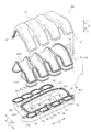
- FIG. 1 is a perspective view from above of an intake device according to an embodiment of the present invention.
- 1 is a perspective view from below of an air intake device according to an embodiment of the present invention. It is the disassembled perspective view which showed the structure of the intake device by one Embodiment of this invention.
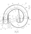
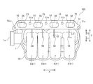
- FIG. 1 is a schematic longitudinal sectional view along an intake passage of an intake device according to an embodiment of the present invention. It is the top view which showed the lower surface side of the lower piece of the intake device by one Embodiment of this invention.
- A is a schematic longitudinal cross-sectional view of an air intake device according to a comparative example.
- B is a schematic longitudinal cross-sectional view of the air intake device according to one embodiment of the present invention.
- C is a typical longitudinal section of the intake device by the modification of one embodiment of the present invention.
- FIGS. 1 to 5 The configuration of an intake system 100 according to an embodiment of the present invention will be described with reference to FIGS. 1 to 5.
- an example of an intake system provided in an in-line four-cylinder engine (not shown) for a vehicle will be described.
- the intake system 100 includes a surge tank 1 (see FIG. 2) and four intake passages 2 branched from the surge tank 1 and disposed downstream of the surge tank 1. Have.
- the intake system 100 is configured to be connected to the cylinder head 90 so that the four intake passages 2 are respectively connected to each cylinder of the engine (internal combustion engine) via an intake port 91 (see FIG. 4). ing.
- the intake device 100 has a three-piece structure in which the intake device main body portion 101 includes an upper piece 3, a middle piece 4 and a lower piece 5.
- the upper piece 3, the middle piece 4 and the lower piece 5 are examples of the “first piece”, the “middle piece” and the “second piece” in the present invention respectively.
- the upper piece 3, the middle piece 4 and the lower piece 5 are formed of a resin material which can be bonded to each other.
- a resin material nylon 6 (PA 6) or the like can be used, for example.
- PA 6 nylon 6
- the upper piece 3, the middle piece 4 and the lower piece 5 are integrally joined to each other by vibration welding, whereby the intake device main body portion 101 is formed.
- the X direction in which the four intake passages 2 are arranged is the horizontal direction
- the middle piece 4 and the lower piece 5 is the vertical direction (Z1 on the upper piece 3 side
- the direction is referred to as the upper direction
- the Z2 direction on the lower piece 5 side is the lower direction
- the Y direction orthogonal to the X direction and the Z direction is the front-rear direction.
- the surge tank 1 includes a partition in the Y2 direction (partitions 41 and 52) and a partition in the Y1 direction (walls 42 and 53). , And the partition wall (wall portion 43) on the Z1 direction side.
- the partition 41 is an example of the "first partition” in the present invention.
- the wall 42 and the wall 43 are examples of the “first surge tank wall” and the “second surge tank wall” in the present invention respectively.
- the partition part 52 is an example of the "2nd partition" of this invention.
- each of the four intake passages 2 communicates with the surge tank 1 and includes an intake passage upstream portion 21 and an intake passage downstream portion 22.
- the intake passage upstream portion 21 communicates with the surge tank 1 at the upstream end portion (inlet portion) 21 a and is a passage portion that curves and extends from the lower portion of the surge tank 1 to the Y1 direction side. ing.
- the intake passage upstream portion 21 is partitioned by the wall portions 54 and 55 in a longitudinal cross section (YZ cross section) along the intake passage 2.
- the intake passage upstream portion 21 is an example of the “circularly extending cylindrical portion” in the present invention.
- the intake passage downstream portion 22 communicates with the intake passage upstream portion 21 at the upstream end, and extends above the surge tank 1 in the Y2 direction to surround the periphery of the surge tank 1 and reaches the downstream end portion 23 It is a passage part.
- a portion (a portion of the range L1) in the vicinity of the downstream end portion 23 (flange portion 51) of the intake passage downstream portion 22 extends in the vertical direction (Z direction) along the Y2 direction side surface of the surge tank 1.
- the intake passage downstream portion 22 includes the wall portions 31, 43, 45, 56, and a partition (partition portions 41 and 52) on the Y2 direction side of the surge tank 1. It is divided by.
- Each intake passage 2 extends to surround the periphery of the surge tank 1 by the intake passage upstream portion 21 and the intake passage downstream portion 22, and intake in the vicinity of a connection portion (flange portion 51) with the intake port 91.
- the passage downstream portion 22 is provided to extend along the side surface of the surge tank 1.
- the Y2 direction side surface of the surge tank 1 in the intake device main body portion 101 and the portion L1 and the downstream end portion 23 of the intake passage downstream portion 22 It is divided by one partition.
- the partition 41 and the wall 43 both define the surge tank 1 and the intake passage downstream portion 22.
- the upper piece 3 is provided so as to cover the upper (Z1 direction side) portion of the middle piece 4, and the intake passage downstream portion 22 of the four intake passages 2 aligned in the X direction.
- Upper piece 3 integrally includes a wall portion 31 which divides intake passage downstream portion 22 in a longitudinal cross section (YZ cross section) along intake passage 2 shown in FIG. 4.
- the upper piece 3 is joined to the middle piece 4 at the joining portion 32.
- the middle piece 4 constitutes the surge tank 1 and is joined to the upper piece 3 on the upper surface side and joined to the lower piece 5 on the lower surface side.
- the middle piece 4 is formed with an upper portion 11 corresponding to approximately 3 ⁇ 4 of the surge tank 1, and the middle piece 4 has a longitudinal cross section (YZ cross section along the intake passage 2).
- the wall portions 42 and 43 which define the upper portion 11 and the partition portion 41 described above are integrally included.
- the wall portion 42 is disposed on the side (the Y1 direction side) opposite to the partition portion 41 in the surge tank 1.
- the wall 43 connects the Z1 direction end of the partition 41 to the Z1 direction end of the wall 42.
- the middle piece 4 constitutes a substantially half of the lower side (Z2 direction side) of the intake passage downstream portion 22 of the intake passage 2.
- the upper piece 3 and the middle piece 4 constitute an intake passage downstream portion 22 communicating with the intake passage upstream portion 21 except for the downstream end portion 23 formed in the lower piece 5.
- the portion of the range L1 extending in the vertical direction (Z direction) along the Y2 direction side surface of the surge tank 1 and the upper portion 11 of the surge tank 1 do not separate from each other. It is arranged to be adjacent via a single partition 41. Further, on the lower end surface of the partition wall portion 41, a second bonding portion 44 to be bonded to a first bonding portion 58 described later of the lower piece 5 is provided.
- the partition portion 41 is formed to extend linearly in the Z direction from the second joint portion 44 in a longitudinal cross section (YZ cross section) along the intake passage 2 (the intake passage upstream portion 21 and the intake passage downstream portion 22) There is.
- the intake passage downstream portion 22 is divided by the partition 41 and the wall 45 (and the wall 31 of the upper piece 3) in the range L1. It is done.
- a joint 46 with the lower piece 5 is provided.
- the partition 41 of the middle piece 4 has a thickness t1 at the second bonding portion 44, and the thickness t1 is for bonding the second bonding portion 44 to the first bonding portion 58 of the lower piece 5. It has a sufficient thickness.
- the lower piece 5 integrally includes an intake passage upstream portion 21 communicating with the surge tank 1 and is joined to the lower surface of the middle piece 4 on the upper surface side.
- the lower piece 12 is provided with the lower portion 12 corresponding to about 1 ⁇ 4 of the surge tank 1 and the intake passage upstream portion 21 having a substantially arc cylindrical shape. The whole of is formed.
- the lower end portion 23 of the intake passage downstream portion 22 having the flange portion 51 connecting the intake passage downstream portion 22 and the intake port 91 is integrally formed on the lower piece 5.
- lower piece 5 integrally has a wall portion 53 and a partition portion 52 which divides lower portion 12 constituting surge tank 1 in a longitudinal cross section (YZ cross section) along intake passage 2 shown in FIG. 4. It contains. Lower piece 5 also includes wall portions 54 and 55 that define intake passage upstream portion 21. Lower piece 5 also includes a wall 56 that defines downstream end portion 23 together with partition 52.
- the intake passage upstream portion 21 of the lower piece 5 is formed of a cylindrical portion extending in an arc shape along the intake passage 2, and the flow passage width is gradually increased from the downstream side toward the upstream side (FIG.
- the gap between the wall 54 and the wall 55 in the longitudinal cross section of the passage 2 is formed to be large.
- the intake passage upstream portion 21 of the lower piece 5 has a single piece cylindrical intake passage shape by using the rotary slide mold core C (see the two-dot chain line in FIG. 4). It is possible to form That is, after the wall portion (wall portion 54 and wall portion 55) is formed in a cylindrical shape around the mold core C corresponding to the intake passage upstream portion 21, the lower piece 5 is relative to the mold core C in the A direction.
- the shape in which the flow passage width of the intake passage upstream portion 21 increases toward the upstream side also functions as a draft of the mold core C.
- the lower piece 5 is joined to the upstream end of the intake passage downstream portion 22 of the middle piece 4 at joints 57 a and 57 b of the downstream end of the intake passage upstream portion 21.
- the flange portion 51 protrudes outward (mainly in the X direction) including the partition wall 52 and the wall 56 at the outer peripheral portion of the downstream end portion 23 of the intake passage downstream portion 22. It is provided as. Specifically, the flange portion 51 is formed so as to connect the respective downstream end portions 23 of the four intake passages 2 in the X direction and to project further outward in the X direction at both end portions in the X direction. . A plurality of holes 51a for connecting with the cylinder head of the engine are formed at positions between the intake passages 2 (the downstream end portions 23) and at both ends of the flange 51 in the X direction. There is.
- the intake device 100 is connected (fastened) to the engine side by inserting a collar and a fastening member (not shown) into the hole 51a.
- the flange portion 51 is adjacent to the upstream side end portion of the cylindrical intake passage upstream portion 21 extending in an arc shape in a longitudinal cross section (YZ cross section) along the intake passage 2 shown in FIG. It is formed as.
- the flange portion 51 (the downstream end portion 23) of the lower piece 5 and the wall portion on the flange portion 51 side (the Y2 direction side) of the lower portion 12 of the surge tank 1 are adjacent and integrated. It has been That is, the flange portion 51 (the downstream end portion 23) and the lower portion 12 of the surge tank 1 are partitioned by the common partition portion 52 without being separated in the Y direction.
- the flange portion 51 is provided so as to connect the plurality of intake passage downstream portions 22 to each other, and is adjacent to and integrated with the wall portion on the flange portion 51 side of the surge tank 1.
- the lower piece 5 is provided with a first joint portion 58 joined to the middle piece 4 on the upper surface of the partition wall 52.
- the joint line of the wall portion constituting flange portion 51 and lower portion 12 of surge tank 1 is formed continuously without interruption. It is done.
- a portion disposed in the partition 52 between the flange 51 and the lower portion 12 is a first joint 58.
- the thickness t1 of the second bonding portion 44 and the thickness t2 of the first bonding portion 58 are substantially equal to each other.
- the thickness t2 is sufficient to join the first joint portion 58 with the second joint portion 44 of the middle piece 4.
- the lower piece 5 performs the second bonding of the middle piece 4 at the first bonding portion 58 of the partition 52 and the bonding portion 57c of the upper end surface of the wall 56.
- the surge tank 1 including the
- reinforcement ribs 59 are provided in portions between the flange portion 51 and the lower portion 12 of the surge tank 1 and the intake passage upstream portion 21. Is provided.
- the reinforcing rib 59 has an outer surface on the surge tank 1 (lower portion 12) side (Y1 direction side) of the flange portion 51, and a wall on the flange portion 51 side (Y2 direction side) of the lower portion 12 and the intake passage upstream portion 21.
- the lower piece 5 is integrally formed so as to connect with the outer surface of the part. That is, as shown in FIG.
- the reinforcing rib 59 is formed to extend not only to the outer surface of the lower portion 12 of the lower piece 5 but also to the outer surface of the wall 55 of the intake passage upstream portion 21. Further, the reinforcing rib 59 is formed to extend in the tangential direction toward the outer surface of the wall portion of the intake passage upstream portion 21 from the end portion of the flange portion 51 on the surge tank 1 side. More specifically, the reinforcing rib 59 extends over a wide range of the length L2 from the lower end portion of the flange portion 51 in the Y2 direction to the intersection point of the tangent drawn to the wall portion 55 of the intake passage upstream portion 21. It is formed. Further, as shown in FIG.
- a plurality of reinforcing ribs 59 are provided so as to connect the flange portion 51 and the respective wall portions of the plurality of intake passage upstream portions 21.
- four reinforcing ribs 59 are formed for each intake passage 2 in total.
- Each reinforcing rib 59 is formed at the central portion of each intake passage 2 in the X direction, and has a plate-like shape with a thickness t3.
- FIG. 6A shows, as a comparative example, an intake device S in which a flange portion is provided on the middle piece and the surge tank and the flange portion are separated in the Y direction with a space D1.
- the conventional configuration is adopted only at the point that the flange portion is provided on the middle piece and the surge tank and the flange portion are separated in the Y direction.
- This is a virtual configuration example configured to be closer to the intake device 100 of
- FIG. 6 (B) shows the intake device 100 of the present embodiment shown in FIGS.
- an intake device 200 is configured in which the device dimensions (dimensions in the Y direction) of the intake device 100 of the present embodiment match the intake device S of the comparative example. It shows.
- the flange portion 51s is formed in the middle piece 4s, and the lower piece 5s includes the intake passage upstream portion 21s and the lower portion of the surge tank 1s. Contains only That is, the lower end portion that constitutes a part of the intake passage downstream portion 22s of the intake passage 2s is not formed in the lower piece 5s. Therefore, the lower piece 5s is joined to the middle piece 4s by vibration welding at the side wall 47s of the surge tank 1s.
- the middle piece 4s and the lower piece 5s are moved (slided) relative to each other on the side wall 47s to perform vibration welding, so that a space D (relative movement) for vibration welding is provided for the distance D1.
- the intake system S is configured such that the bending radius R1 of the intake passage upstream portion 21s is substantially equal to the bending radius R1 of the intake passage upstream portion 21 of the intake device 100 of the present embodiment shown in FIG. An example is shown. Note that the bending radius shown here is the radius of the arc shown generally along the passage center line of the intake passage, and as described above, the channel width is not constant, so An arc) is shown as the radius of the arc.
- a single partition (partitions 41 and 52) is provided between the intake passage downstream portion 22 including the flange 51 and the surge tank 1.
- the lower piece 5 is joined to the middle piece 4 at the first joint portion 58 and the joint portions 57a, 57b, 57c and 57d when viewed in a longitudinal cross section (YZ cross section) along the intake passage 2. In this case, it is not necessary to secure a space for vibration welding inside the intake device 100.
- the surge tank 1 and the intake passage upstream portion 21 can be disposed for the total distance D2 of the thickness t4 of the side wall 47s and the interval D1 compared to the intake system S. It is possible to secure an internal space.
- the size of the intake device 100 is made compact by the length L3 in the Y direction.
- the side wall of the intake device 200 according to the modification of the present embodiment in which the entire length in the Y direction of the device matches the intake device S of the comparative example. It is possible to secure an internal space in which the surge tank 101 and the intake passage upstream portion 121 can be disposed by the total distance D2 of the thickness t4 of 47 s and the interval D1.
- the intake passage upstream portion 121 is configured with a bending radius R2 larger than the radius R1.
- the intake passage upstream portion 121 is an example of the “circularly extending cylindrical portion” in the present invention.
- the intake device S of the comparative example is structurally located in a portion S1 on the Y2 direction side of the surge tank 1s in the intake passage downstream portion 22s, the surge tank 1s and the intake passage upstream.
- a portion S2 on the Y1 direction side in which the portion 21s is disposed is separated from the space D1. Therefore, when the intake device S is attached to the engine side by the flange portion 51s that is a connection portion with the cylinder head, the Y2 direction side portion S1 of the intake device S is the Y1 direction side portion (surge tank 1s and the intake passage upstream portion) 21s) It has a structure to support S2.
- the Y1 direction side portion S2 which is a weight portion, is supported at the tip of the cantilever Y2 direction side portion S1.
- the intake system S it becomes difficult to suppress the vibration of the Y1 direction side portion S2.
- the Y2 direction side portion (the intake passage downstream portion 22) and the Y1 direction side portion (the surge tank 1 and the intake passage upstream portion 21) There is no gap between them, and the flange portion 51 which is the connection portion and the Y1 direction side portion (the surge tank 1 and the intake passage upstream portion 21) are integrally connected in the lower piece 5 by the partition 52 at the shortest distance. .
- the rigidity of the entire intake system 100 is improved as compared with the intake system S of the comparative example, and the vibration in the Y1 direction side portion which is the weight portion is suppressed. Is possible. This point is the same as that of the intake device 200 of the modification shown in FIG. 6 (C).
- the lower piece 5 is provided with the flange portion 51 connecting the intake passage downstream portion 22 and the intake port 91 to the vicinity of the intake passage upstream portion 22 communicating with the surge tank 1 in the lower piece 5.
- Side wall of the lower portion 12 and the side wall of the flange portion 51 by a joint surface (first joint portion 58) with the middle piece 4 to form a single side wall (partition wall portion 52) Can. Therefore, also on the middle piece 4 side joined to the lower piece 5, the side wall of the surge tank 1 (upper portion 11) and the side wall of the intake passage downstream portion 22 are connected to form a single side wall (partition 41). Thus, it can be joined to a single side wall (partition 52) of the lower piece 5.
- the intake device 100 can be miniaturized. Further, in the present embodiment, by providing the flange portion 51 on the lower piece 5, the vibration transmitting portion (flange portion 51) and the weight portion (surge tank 1 side portion) of the intake device 100 are connected at a short distance in the lower piece 5. Therefore, the vibration of the entire intake device 100 can be suppressed.
- the degree of freedom in design for meeting the required specifications can be increased without increasing the size of the device. Is possible. As a result of these, it is possible to increase the degree of freedom of design when mounting the intake system 100 (200) in a limited space, and therefore it is possible to improve the mountability (easiness of mounting) of the intake system. .
- the flange portion 51 of the lower piece 5 and the wall portion on the flange portion 51 side of the surge tank 1 of the lower piece 5 are adjacently integrated by the partition portion 52. Then, a first joint portion 58 joined to the middle piece 4 is provided in the partition portion 52.
- the flange portion 51 and the lower portion 12 of the surge tank 1 can be integrated without being separated, the size can be reduced accordingly.
- the flange portion 51 which is a connecting portion with the intake port 91 is integrated with the surge tank 1 (lower portion 12) in the lower piece 5, the rigidity of the entire intake device 100 can be improved. Vibration of the intake system 100 at the time of driving the engine can also be suppressed.
- the surge tank 1 (upper portion 11) of the middle piece 4 and the intake passage downstream portion 22 of the middle piece 4 are adjacent via the single partition portion 41.
- the partition wall portion 41 is provided with a second joint portion 44 joined to the first joint portion 58 of the lower piece 5.
- the surge tank 1 and the intake passage downstream portion 22 can be integrated by the single (common) partition portion 41.
- the partition 41 and the wall 43 are both provided to separate the surge tank 1 and the intake passage downstream portion 22.
- the surge tank 1 and the intake passage downstream portion 22 can be integrated by the common partition wall in a wider range of the partition wall portion 41 and the wall portion 43.
- the intake device 100 can be further miniaturized, and the rigidity of the entire intake device 100 can be easily improved.
- the partition portion 41 is linearly extended from the second joint portion 44. Form. Thereby, since the shape of the partition part 41 can be simplified, when forming the middle piece 4, the partition part 41 and the 2nd junction part 44 can be formed easily.
- the thickness t1 of the second bonding portion 44 and the thickness t2 of the first bonding portion 58 are equal to each other. Therefore, if the thickness of the second joint portion 44 and the first joint portion 58 is sufficiently secured to join each other, a common partition wall having the minimum necessary thickness for the intake passage downstream portion 22 and the surge tank 1 It can be integrated through (partitions 41 and 52). As a result, it is not necessary to increase the thickness of the partition wall more than necessary.
- a plurality of intake passage upstream portions 21 and a plurality of intake passage downstream portions 22 are provided.
- the flange portion 51 is provided to connect the plurality of intake passage downstream portions 22 with each other, and the wall portion on the flange portion 51 side of the surge tank 1 (lower portion 12) and the flange portion 51 are adjacent to each other. Integrate. As a result, it is not necessary to integrate each of the plurality of intake passage upstream portions 21 with the flange portion 51, and only the flange portion 51 and the surge tank 1 may be integrated, so the structure of the lower piece 5 is simplified. be able to.
- the downstream end portion 23 of the intake passage downstream portion 22 provided with the flange portion 51 is adjacent to the surge tank 1 (lower portion 12) to be a common partition wall portion Divide by 52.
- the surge tank 1 and the intake passage downstream portion 22 can be adjacent via the common partition 52.
- the overall size of the intake system 100 can be reduced, and the rigidity of the intake system 100 can be improved.
- the flange portion 51s of the middle piece 4s and the lower piece 5s are separate pieces. It becomes impossible to form a reinforcement rib.
- the flange portion 51, the surge tank 1 (lower portion 12), and the intake passage upstream portion 21 are formed in the same lower piece 5. Since it is formed, the rigidity of the intake device 100 can be easily improved with a simple configuration in which only the reinforcing rib 59 is provided.
- the reinforcing rib 59 is formed to extend over the range of the length L2 to the outer surface of the wall 55 corresponding to the upstream portion 21 of the intake passage of the lower piece 5. .
- the reinforcing rib 59 can be provided in a wide range from the surge tank 1 to the intake passage upstream portion 21, the rigidity of the intake device 100 can be more effectively improved.
- the reinforcing rib 59 is formed so as to extend in the tangential direction toward the outer surface of the wall portion of the intake passage upstream portion 21 from the end of the flange portion 51 on the surge tank 1 side.
- a plurality of reinforcing ribs 59 are provided so as to connect the flange portion 51 and the respective wall portions of the plurality of intake passage upstream portions 21.
- the rigidity can be improved by the reinforcing rib 59 for each of the individual intake passage upstream portions 21.
- the intake passage upstream portion 21 of the lower piece 5 is formed in a cylindrical shape extending in an arc along the intake passage, and the flange portion 51 is a cylindrical shape extending in an arc. It is formed to be adjacent to the upstream portion 21 of the intake passage.
- the lower piece 5 in which the cylindrical portion (intake passage upstream portion 21) extending in an arc shape is formed can be formed as a single piece by using the rotary slide type mold core C.
- the flange portion 51 provided on the lower piece 5 is rotated relative to the mold core C in the A direction (see FIG. 4) with respect to the process of extracting the lower piece 5 and the mold core C (see FIG. 4). Since it can utilize also as an engaging part in the process of extracting from, it is not necessary to separately provide an engaging part for extraction on the outer surface of the lower piece 5.
- the intake passage upstream portion 21 is formed such that the flow passage width increases from the downstream side toward the upstream side. As a result, a draft at the time of removing the molded product (cylindrical part) from the mold core can be formed in the intake passage upstream portion 21. As a result, the lower piece 5 can be formed more easily.
- the upper piece 3, the middle piece 4 and the lower piece 5 are formed of a resin that can be bonded to each other.
- upper piece 3, middle piece 4 and lower piece 5 can be easily joined by vibration welding.
- the intake system of this invention may be applied to an intake system for an internal combustion engine other than an automobile engine, or to an intake system for an automobile engine other than an in-line four-cylinder engine.
- the intake system may be configured with four or more pieces.
- the example which provided a part (lower part) of a surge tank and the intake passage upstream part in the lower piece in the said embodiment was shown, this invention is not limited to this.
- the lower piece may be provided with only the upstream portion of the intake passage without forming the lower portion of the surge tank.
- the intake passage upstream portion and the flange portion 51 (downstream end portion) may be configured to be partitioned by a single partition portion.
- the reinforcing rib is provided in the range (see FIG. 4) of the length L2 between the flange portion of the lower piece and the surge tank (lower portion) and the intake passage upstream portion.
- the present invention is not limited to this.
- the reinforcing rib may be provided in a range shorter than the length L2.
- the reinforcing rib may be provided only at a portion between the flange portion and the surge tank (lower portion) without extending to the intake passage upstream portion.
- the intake passage upstream portion of the lower piece is formed in a cylindrical shape extending in an arc shape, and can be formed in a single piece using a rotary slide type mold core.
- the lower piece may be divided into upper and lower parts to form an upper lower piece and a lower lower piece with a normal mold, and then the upper lower piece and the lower lower piece may be joined to form the lower piece. In this case, in FIG.
- the middle portion in the vertical direction of the intake passage upstream portion 21 may be divided into two, and the flange portion 51 (downstream end portion 23), the lower portion 12 of the surge tank 1, and the intake passage upstream portion
- the lower piece 5 can be configured by joining the upper lower piece including the upper portion of the upper portion 21 and the lower lower piece including the lower portion of the intake passage upstream portion 21.
- the upper piece, the middle piece, and the lower piece with the resin material which can mutually be joined was shown in the said embodiment, this invention is not limited to this.
- the upper piece, the middle piece, and the lower piece may be made of a material other than a resin material.
Abstract
This intake system is provided with a first piece, a middle piece which configures a surge tank and is joined to the first piece, and a second piece which includes an intake passage upstream portion that communicates with the surge tank and which is joined to the middle piece. The first piece and the middle piece configure an intake passage downstream portion that communicates with the intake passage upstream portion, and the second piece further includes a flange which links the intake passage downstream portion and the intake port of an internal combustion engine.
Description
本発明は、吸気装置に関する。
The present invention relates to an intake system.
従来、サージタンクと吸気通路とを複数のピースにより構成した吸気装置が知られている。このような吸気装置は、たとえば、特開2012-251518号公報に開示されている。
Conventionally, an intake system is known in which a surge tank and an intake passage are configured by a plurality of pieces. Such an intake device is disclosed, for example, in Japanese Unexamined Patent Publication No. 2012-251518.
上記特開2012-251518号公報には、上方に位置するアッパーピースと、中間に位置するミドルピースと、下方に位置するロアピースとの3ピース構成の吸気装置が開示されている。この吸気装置では、アッパーピースとミドルピースとにより、吸気通路の下流部が構成され、ミドルピースとロアピースとによってサージタンクおよび吸気通路の上流部が構成される。吸気通路は、上流側でサージタンクと連通するとともに、下流部の端部に設けられたフランジ部でエンジンの吸気ポートと接続される。
In the above-mentioned JP 2012-251518 A, there is disclosed a three-piece intake system of an upper piece positioned at the upper side, a middle piece positioned at the middle, and a lower piece positioned at the lower side. In this intake system, the upper piece and the middle piece constitute the downstream portion of the intake passage, and the middle piece and the lower piece constitute the upstream portion of the surge tank and the intake passage. The intake passage communicates with the surge tank on the upstream side, and is connected to the intake port of the engine at a flange portion provided at the end of the downstream portion.
この特開2012-251518号公報では、フランジ部は、ミドルピースに一体形成されている。また、吸気装置の各ピースは、樹脂製で振動溶着によって互いに接合されている。すなわち、ミドルピースの上側壁部の下端面(溶着ライン)と、ロアピースの下側壁部の上端面(溶着ライン)とを振動溶着することにより、サージタンクの側壁が構成されている。
In JP 2012-251518 A, the flange portion is integrally formed with the middle piece. Further, the pieces of the intake system are made of resin and joined to each other by vibration welding. That is, the side wall of the surge tank is configured by vibration-welding the lower end surface (welding line) of the upper side wall portion of the middle piece and the upper end surface (welding line) of the lower side wall portion of the lower piece.
なお、振動溶着は、接合する部材の接合部同士を摺動(振動)させる必要があるため、接合部近傍に振動のためのスペースが必要となる。そのため、上記特開2012-251518号公報の吸気装置では、ミドルピースの上側壁部と、ロアピースの下側壁部とにより構成されるサージタンクの側壁と、フランジ部が設けられたミドルピースの吸気通路の下流部(下流側端部)の側壁とは、互いに離間して接合用の間隔を隔てて形成されている。
In addition, since it is necessary to make the joined parts of the members to be joined slide (vibrate) in vibration welding, a space for vibration is required near the joined parts. Therefore, in the intake device of JP 2012-251518 A, the intake passage of the middle piece provided with the side wall of the surge tank constituted by the upper side wall portion of the middle piece and the lower side wall portion of the lower piece and the flange portion The side walls of the downstream portion (downstream side end portion) are formed to be separated from each other and for bonding.
ここで、近年では、吸気装置が搭載される車両などのデザイン性の要求から、吸気装置を含めたエンジンスペースの省スペース化が強く望まれている。しかしながら、上記特開2012-251518号公報のような従来の吸気装置では、サージタンクの側壁と、吸気通路の下流部(下流側端部)の側壁との2つの厚肉部(壁部)を接合用の間隔を隔てて配置する必要があるため、吸気装置に接合用の間隔(スペース)を形成する分だけ吸気装置が大型化し、その結果、吸気装置の小型化を図るのが困難であるという問題点がある。また、上記特開2012-251518号公報のような従来の吸気装置では、内燃機関の吸気ポートとの連結部であるフランジ部が、ミドルピースのサージタンクの側壁から間隔を隔てて離間した位置に設けられているため、内燃機関の作動時の振動伝達部分(フランジ部)と、吸気装置の重量部分(サージタンク側部分)とが長い吸気通路を介して長い距離で連結された振動しやすい構造となり、その結果、吸気装置の振動の抑制を図るのが困難であるという問題点もある。
Here, in recent years, space saving of the engine space including the intake device is strongly desired from the requirement of design of the vehicle etc. on which the intake device is mounted. However, in the conventional intake device as disclosed in JP 2012-251518, the two thick portions (walls) of the side wall of the surge tank and the side wall of the downstream portion (downstream end portion) of the intake passage Since it is necessary to arrange at intervals for joining, the intake system is enlarged by an amount corresponding to the interval (space) for joining in the intake system, and as a result, it is difficult to miniaturize the intake system. There is a problem of that. Further, in the conventional intake device as disclosed in JP 2012-251518 A, the flange portion which is the connection portion with the intake port of the internal combustion engine is spaced apart from the side wall of the middle tank surge tank. Since it is provided, a structure susceptible to vibration in which a vibration transmitting portion (flange portion) at the time of operation of the internal combustion engine and a heavy portion (surge tank side portion) of the intake system are connected at a long distance As a result, it is difficult to suppress the vibration of the intake system.
この発明は、上記のような課題を解決するためになされたものであり、この発明の1つの目的は、小型化および振動の抑制を図ることが可能な吸気装置を提供することである。
The present invention has been made to solve the problems as described above, and one object of the present invention is to provide an air intake device capable of achieving downsizing and suppressing vibration.
上記目的を達成するために、この発明の一の局面における吸気装置は、第1ピースと、サージタンクを構成し、第1ピースと接合される中間ピースと、サージタンクと連通する吸気通路上流部を含み、中間ピースと接合される第2ピースとを備え、第1ピースと中間ピースとは、吸気通路上流部と連通する吸気通路下流部を構成し、第2ピースは、さらに、吸気通路下流部と内燃機関の吸気ポートとを連結するフランジ部を含む。
In order to achieve the above object, an intake system according to one aspect of the present invention includes a first piece, a surge tank, an intermediate piece joined to the first piece, and an upstream portion of an intake passage communicating with the surge tank. And a second piece joined to the middle piece, wherein the first piece and the middle piece constitute an intake passage downstream portion in communication with the intake passage upstream portion, and the second piece is further downstream of the intake passage And a flange portion connecting the portion and the intake port of the internal combustion engine.
この発明の一の局面による吸気装置では、上記のように、サージタンクと連通する吸気通路上流部を含み、中間ピースと接合される第2ピースに、吸気通路下流部と内燃機関の吸気ポートとを連結するフランジ部を設けることによって、第2ピースにおいて、サージタンクと連通する吸気通路上流部近傍の側壁と、フランジ部の側壁とを、少なくとも中間ピースとの接合面で連結して単一の側壁にすることができる。そのため、第2ピースと接合される中間ピース側においても、サージタンクの側壁と吸気通路下流部の側壁とを連結して単一の側壁を形成して第2ピースの単一の側壁と接合することができる。これにより、従来必要だった2つの壁部(サージタンクの側壁および吸気通路の下流部の側壁)のうちの一方と、2つの壁部を設ける場合の接合用の間隔とをそれぞれ抹消することができるので、その分、吸気装置の小型化を図ることができる。また、従来の吸気装置と同じサイズであれば、より吸気性能を向上させた吸気装置を得ることができる。これらの結果、限られたスペースに吸気装置を搭載する際の設計の自由度を増加させることができるので、吸気装置の搭載性(搭載のし易さ)を向上させることができる。また、本発明によれば、第2ピースにフランジ部を設けることによって、振動伝達部分(フランジ部)と、吸気装置の重量部分(サージタンク側部分)とを第2ピースにおいて短距離で連結することができるので、吸気装置全体の振動を抑制することができる。
In the intake system according to one aspect of the present invention, as described above, the second piece joined to the intermediate piece includes the intake passage upstream portion in communication with the surge tank, the intake passage downstream portion and the intake port of the internal combustion engine In the second piece, the side wall near the upstream portion of the intake passage communicating with the surge tank and the side wall of the flange portion are connected at least in the joint surface with the intermediate piece in the second piece. It can be a side wall. Therefore, also on the intermediate piece side joined to the second piece, the side wall of the surge tank and the side wall of the intake passage downstream portion are connected to form a single side wall and joined to the single side wall of the second piece be able to. Thereby, it is possible to respectively erase one of the two walls (the side wall of the surge tank and the side wall of the downstream portion of the intake passage) which was conventionally required, and the bonding distance in the case of providing the two walls. Since it can do, part reduction in size of the intake system can be achieved. Moreover, if it is the same size as the conventional intake device, the intake device which improved intake performance more can be obtained. As a result of these, it is possible to increase the degree of freedom in design when the intake device is mounted in a limited space, and therefore the mountability (easiness of mounting) of the intake device can be improved. Further, according to the present invention, by providing the flange portion on the second piece, the vibration transmission portion (flange portion) and the weight portion (surge tank side portion) of the intake device are connected at a short distance in the second piece. As a result, the vibration of the entire intake system can be suppressed.
上記一の局面による吸気装置において、好ましくは、第2ピースのフランジ部と、第2ピースのサージタンクまたは吸気通路上流部のフランジ部側の壁部とは、隣接して一体化されているとともに、隣接して一体化された部分において中間ピースに対して接合される第1接合部が設けられている。このように構成すれば、フランジ部と、サージタンクの第2ピース側部分または吸気通路上流部とを離間させることなく一体化することができるので、その分だけ小型化を図ることができる。また、内燃機関の吸気ポートとの連結部であるフランジ部が第2ピースにおいてサージタンクの第2ピース側部分または吸気通路上流部と一体化されるので、吸気装置全体の剛性を向上させることができ、その結果、内燃機関の駆動時の吸気装置の振動を効果的に抑制することができる。
In the intake system according to the aforementioned aspect, preferably, the flange portion of the second piece and the wall portion on the flange portion side of the surge tank of the second piece or the upstream portion of the intake passage are adjacently integrated. A first joint is provided which is joined to the intermediate piece in the adjacent and integral part. According to this structure, since the flange portion and the second piece side portion of the surge tank or the upstream portion of the intake passage can be integrated without being separated, downsizing can be achieved accordingly. Further, since the flange portion which is the connection portion with the intake port of the internal combustion engine is integrated with the second piece side portion of the surge tank or the upstream portion of the intake passage in the second piece, the rigidity of the entire intake system can be improved. As a result, the vibration of the intake system at the time of driving the internal combustion engine can be effectively suppressed.
この場合において、好ましくは、中間ピースのサージタンクと、中間ピースの吸気通路下流部とは、単一の第1隔壁を介して隣接するように配置されており、第1隔壁は、第2ピースの第1接合部と接合される第2接合部を含む。このように構成すれば、第2ピースのみならず中間ピース側でも、サージタンクと吸気通路下流部とを単一(共通)の第1隔壁によって一体化することができる。その結果、サージタンクのフランジ部側(吸気通路下流部側)の側面の広い範囲で、吸気通路下流部とサージタンクとを単一(共通)の隔壁を介して一体化することができるので、容易に吸気装置の小型化を図ることができ、吸気装置の搭載性を容易に向上させることができる。また、第2ピースに加えて、中間ピースのサージタンクと吸気通路下流部とが隣接して間の第1隔壁が一体化されるので、吸気装置全体の剛性を容易に向上させることができる。
In this case, preferably, the surge tank of the intermediate piece and the downstream portion of the intake passage of the intermediate piece are disposed adjacent to each other via a single first partition, and the first partition is the second piece And a second joint joined with the first joint. According to this structure, the surge tank and the downstream portion of the intake passage can be integrated by the single (common) first partition wall not only on the second piece but also on the intermediate piece side. As a result, the downstream portion of the intake passage and the surge tank can be integrated via a single (common) partition in a wide range of the side surface of the flange portion side (the downstream side of the intake passage) of the surge tank. The intake device can be easily miniaturized, and the mountability of the intake device can be easily improved. Further, in addition to the second piece, the first partition wall between the surge tank of the intermediate piece and the downstream portion of the intake passage adjacent to each other is integrated, so that the rigidity of the entire intake device can be easily improved.
上記サージタンクと吸気通路下流部とが第1隔壁を介して隣接する構成において、好ましくは、サージタンクは、第1隔壁と、第1隔壁とは反対側の第1サージタンク壁部と、第1隔壁の端部と第1サージタンク壁部の端部とを接続する第2サージタンク壁部とを含み、第1隔壁および第2サージタンク壁部は、共に、サージタンクと吸気通路下流部とを区画している。このように構成すれば、第1隔壁と第2サージタンク壁部とのより広い範囲でサージタンクと吸気通路下流部とを共通の隔壁によって一体化することができる。これにより、吸気装置をより一層小型化することができるとともに、吸気装置全体の剛性を容易に向上させることができる。
Preferably, in the above-described configuration in which the surge tank and the intake passage downstream portion are adjacent to each other via the first partition, the surge tank includes the first partition, a first surge tank wall opposite to the first partition, and A second surge tank wall connecting the end of the first partition and the end of the first surge tank wall, wherein both the first partition and the second surge tank wall are connected to the surge tank and the intake passage downstream; And partition. According to this structure, the surge tank and the downstream portion of the intake passage can be integrated by the common partition in a wider range of the first partition and the second surge tank wall. Thus, the intake device can be further miniaturized, and the rigidity of the entire intake device can be easily improved.
上記第1隔壁が第2ピースの第1接合部と接合される第2接合部を含む構成において、好ましくは、第1隔壁は、吸気通路上流部および吸気通路下流部に沿った縦断面において、第2接合部から直線状に延びるように形成されている。このように構成すれば、第1隔壁の形状を単純にすることができるので、たとえば樹脂成形によって中間ピースを形成する場合に、第1隔壁および第2接合部を容易に形成することができる。
In the configuration including the second joint where the first partition is joined to the first joint of the second piece, preferably, the first partition is a longitudinal cross section along the intake passage upstream portion and the intake passage downstream portion, It is formed to extend linearly from the second joint. According to this structure, since the shape of the first partition can be simplified, the first partition and the second joint can be easily formed, for example, when the intermediate piece is formed by resin molding.
上記第1隔壁が第2ピースの第1接合部と接合される第2接合部を含む構成において、好ましくは、第2接合部の肉厚と、第1接合部の肉厚とは、互いに等しい。このように構成すれば、第2接合部および第1接合部の肉厚を互いに接合するのに十分なだけ確保すれば、吸気通路下流部とサージタンクとを最低限必要な厚みの共通の隔壁を介して一体化することができる。この結果、隔壁部分の肉厚を必要以上に大きくせずに済む。
In the configuration including the second joint where the first partition is joined to the first joint of the second piece, preferably, the thickness of the second joint and the thickness of the first joint are equal to each other. . According to this structure, if the wall thickness of the second joint portion and the first joint portion is sufficiently secured to join each other, a common partition wall having a minimum necessary thickness for the downstream portion of the intake passage and the surge tank Can be integrated. As a result, it is not necessary to increase the thickness of the partition wall more than necessary.
上記中間ピースのサージタンクと、中間ピースの吸気通路下流部とが単一の第1隔壁を介して隣接する構成において、好ましくは、吸気通路上流部および吸気通路下流部は複数設けられており、フランジ部は、複数の吸気通路下流部のそれぞれを互いに接続するように設けられるとともに、サージタンクのフランジ部側の壁部と隣接して一体化されている。このように構成すれば、複数の吸気通路上流部のそれぞれとフランジ部とを一体化させる必要がなく、フランジ部とサージタンクとを一体化させるだけで済むので、第2ピースの構造を簡素化することができる。
In the configuration in which the surge tank of the intermediate piece and the intake passage downstream portion of the intermediate piece are adjacent to each other via a single first partition, preferably, a plurality of intake passage upstream portions and a plurality of intake passage downstream portions are provided. The flange portion is provided to connect each of the plurality of intake passage downstream portions to each other, and is integrated adjacent to the flange portion side wall portion of the surge tank. According to this structure, the structure of the second piece is simplified because it is not necessary to integrate each of the plurality of intake passage upstream portions with the flange portion, and it is sufficient to integrate the flange portion and the surge tank. can do.
この場合において、好ましくは、フランジ部が設けられた吸気通路下流部の下流端部分と、サージタンクとは、隣接して共通の第2隔壁によって区画されている。このように構成すれば、第2ピース側にサージタンクの一部が形成される場合に、中間ピースのみならず第2ピースでも、サージタンクと吸気通路下流部とを共通の第2隔壁を介して隣接させることができる。この結果、吸気装置全体の小型化と、吸気装置の剛性の向上とを図ることができる。
In this case, preferably, the downstream end portion of the intake passage downstream portion provided with the flange portion and the surge tank are partitioned adjacently by the common second partition wall. According to this structure, when a part of the surge tank is formed on the second piece side, not only the intermediate piece but also the second piece, the surge tank and the intake passage downstream portion are common via the second partition wall. Can be adjacent to each other. As a result, the overall size of the intake system can be reduced, and the rigidity of the intake system can be improved.
上記一の局面による吸気装置において、好ましくは、第2ピースは、フランジ部のサージタンク側の外面と、サージタンクまたは吸気通路上流部のフランジ部側の壁部の外面とを接続するように設けられた補強リブを含む。このように構成すれば、内燃機関の吸気ポートとの連結部であるフランジ部とサージタンクまたは吸気通路上流部との間を補強することができるので、吸気装置の剛性をより一層向上させることができ、その結果、吸気装置全体の振動をより抑制することができる。また、従来の吸気装置のようにフランジ部(吸気通路下流部)がミドルピースに設けられる場合には、フランジ部とロアピースのサージタンクまたは吸気通路上流部とが別ピースになり補強リブを一体形成することができない。これに対して、本発明によれば、フランジ部と、サージタンクの第2ピース側部分または吸気通路上流部とが同一の第2ピースに形成されるので、補強リブを設けるだけの簡単な構成で容易に吸気装置の剛性を向上させることができる。
In the intake system according to the aforementioned aspect, preferably, the second piece is provided to connect the outer surface of the flange portion on the surge tank side and the outer surface of the surge tank or the wall portion on the flange portion upstream side of the intake passage. Containing reinforced ribs. According to this structure, it is possible to reinforce between the flange portion, which is a connection portion with the intake port of the internal combustion engine, and the surge tank or the upstream portion of the intake passage, thereby further improving the rigidity of the intake device. As a result, vibration of the entire intake system can be further suppressed. When the flange portion (downstream portion of the intake passage) is provided on the middle piece as in the conventional intake device, the flange portion and the surge tank of the lower piece or the upstream portion of the intake passage are separate pieces and the reinforcing rib is integrally formed. Can not do it. On the other hand, according to the present invention, since the flange portion and the second piece side portion of the surge tank or the upstream portion of the intake passage are formed in the same second piece, the simple structure only having the reinforcing rib is provided. The rigidity of the intake system can be easily improved.
この場合において、好ましくは、補強リブは、第2ピースのサージタンクに対応する部分のみならず、第2ピースの吸気通路上流部に対応する壁部の外面まで延びるように形成されている。このように構成すれば、サージタンクから吸気通路上流部に達する広い範囲で補強リブを設けることができるので、より効果的に吸気装置の剛性を向上させることができる。
In this case, preferably, the reinforcing rib is formed to extend not only to the portion corresponding to the surge tank of the second piece but also to the outer surface of the wall portion corresponding to the upstream portion of the intake passage of the second piece. According to this structure, since the reinforcing rib can be provided in a wide range from the surge tank to the upstream portion of the intake passage, the rigidity of the intake device can be more effectively improved.
上記補強リブが第2ピースの吸気通路上流部に対応する壁部の外面まで延びる構成において、好ましくは、補強リブは、フランジ部のサージタンク側の端部から、吸気通路上流部の壁部の外面に向かう接線方向に延びるように形成されている。このように構成すれば、補強リブをより広い範囲で設けることができるので、より効果的に吸気装置の剛性を向上させることができる。
In the configuration in which the reinforcing rib extends to the outer surface of the wall corresponding to the upstream portion of the intake passage of the second piece, preferably, the reinforcing rib is from the end on the surge tank side of the flange portion of the wall of the upstream portion of the intake passage. It is formed to extend in a tangential direction toward the outer surface. According to this structure, since the reinforcing rib can be provided in a wider range, the rigidity of the intake device can be more effectively improved.
上記補強リブが第2ピースの吸気通路上流部に対応する壁部の外面まで延びる構成において、好ましくは、吸気通路上流部および吸気通路下流部は複数設けられており、補強リブは、フランジ部と、複数の吸気通路上流部の各々の壁部とを接続するように複数設けられている。このように構成すれば、複数の吸気通路上流部を設ける場合にも、個々の吸気通路上流部ごとに補強リブによって剛性を向上させることができる。
In the configuration in which the reinforcement rib extends to the outer surface of the wall corresponding to the intake passage upstream portion of the second piece, preferably, a plurality of intake passage upstream portions and a plurality of intake passage downstream portions are provided. A plurality of air intake passages are provided so as to connect with the respective wall portions of the plurality of intake passage upstream portions. According to this structure, even in the case where a plurality of intake passage upstream portions are provided, the rigidity can be improved by the reinforcing rib for each individual intake passage upstream portion.
上記一の局面による吸気装置において、好ましくは、第2ピースの吸気通路上流部は、吸気通路に沿って円弧状に延びる筒状部を有し、フランジ部は、円弧状に延びる筒状部を有する吸気通路上流部に隣接するように形成されている。このように構成すれば、円弧状に延びる筒状部を有する吸気通路上流部が形成される第2ピースを、回転スライド式の金型コアを用いて単一ピースで形成することができる。ここで、回転スライド式の金型コアを用いる場合、成型品の外表面に係合部を設ける必要があり、係合部を回転方向に押圧することによって金型コアからの成型品(筒状部)の抜き取り工程が行なわれる。これに対して、本発明によれば、第2ピースに設けたフランジ部を抜き取り工程における係合部としても利用することができるので、第2ピースの外表面に抜き取り用の係合部を別途設ける必要がない。
In the intake system according to the aforementioned aspect, preferably, the intake passage upstream portion of the second piece has a cylindrical portion extending in an arc along the intake passage, and the flange portion is a cylindrical portion extending in an arc. It is formed to be adjacent to the upstream portion of the intake passage. According to this structure, the second piece in which the intake passage upstream portion having the cylindrical portion extending in an arc shape is formed can be formed as a single piece by using a rotary slide type mold core. Here, in the case of using a rotary slide type mold core, it is necessary to provide an engagement portion on the outer surface of the molded product, and pressing the engagement portion in the rotational direction results in molding of the mold core (cylindrical shape Part) is carried out. On the other hand, according to the present invention, the flange portion provided on the second piece can also be used as the engagement portion in the extraction step, so the extraction engagement portion is separately provided on the outer surface of the second piece. There is no need to provide it.
この場合において、好ましくは、筒状部は、下流側から上流側に向かうに従って流路幅が大きくなるように形成されている。このように構成すれば、金型コアからの成型品(筒状部)を抜き取る際の抜き勾配を筒状部に形成することができる。これにより、第2ピースを単一ピースで形成する場合にも、より容易に第2ピースを形成することができる。
In this case, preferably, the tubular portion is formed such that the flow passage width increases from the downstream side toward the upstream side. According to this structure, it is possible to form, in the cylindrical portion, a draft at the time of extracting the molded product (cylindrical portion) from the mold core. Thus, the second piece can be more easily formed even when the second piece is formed as a single piece.
上記一の局面による吸気装置において、好ましくは、第1ピース、中間ピースおよび第2ピースは、互いに接合可能な樹脂により形成されている。このように構成すれば、第1ピース、中間ピースおよび第2ピースを振動溶着などの溶着法を用いて容易に接合することができる。その場合にも、従来必要だった2つの壁部(サージタンクの側壁および吸気通路の下流部の側壁)のうちの一方と、2つの壁部を設ける場合の接合用の間隔とをそれぞれ抹消することができるので、その分、吸気装置の小型化および搭載性の向上を図ることができる。
In the air intake system according to the aforementioned aspect, preferably, the first piece, the intermediate piece and the second piece are formed of a resin which can be bonded to each other. According to this structure, the first piece, the intermediate piece and the second piece can be easily joined using a welding method such as vibration welding. Also in this case, one of the two walls conventionally required (the side wall of the surge tank and the side wall of the downstream portion of the intake passage) and the gap for joining in the case of providing the two walls are erased respectively As a result, it is possible to reduce the size and mountability of the intake system accordingly.
なお、本出願では、上記一の局面による吸気装置とは別に、以下のような他の構成も考えられる。
In the present application, apart from the air intake device according to the above-described one aspect, the following other configurations are also conceivable.
すなわち、本出願の他の構成による吸気装置は、サージタンクと、サージタンクと連通するとともに内燃機関の吸気ポートに接続される吸気通路とが形成された吸気装置本体部を備え、吸気通路は、サージタンクの周囲を囲むように延びるとともに、吸気ポートとの接続部近傍の下流部においてサージタンクの側面に沿って延びるように設けられ、吸気装置本体部におけるサージタンクの側面と吸気通路の下流部とは、単一の隔壁部により区画されている。このように構成すれば、サージタンクの側壁と吸気通路の下流部の側壁とを連結して単一の隔壁部により区画することができる、その結果、従来必要だった2つの壁部(サージタンクの側壁および吸気通路の下流部の側壁)のうちの一方と、2つの壁部を設ける場合の接合用の間隔とをそれぞれ抹消することができるので、その分、吸気装置の小型化を図ることができる。この結果、限られたスペースに吸気装置を搭載する際の設計の自由度を増加させることができるので、吸気装置の搭載性(搭載のし易さ)を向上させることができる。また、サージタンクと吸気通路の下流部とを間隔を隔てて離間させることなく単一の隔壁部を介して一体化することができるので、吸気装置全体の剛性を向上させ、吸気装置の振動の抑制を図ることができる。
That is, an intake system according to another configuration of the present application includes an intake system main body portion in which a surge tank and an intake passage communicating with the surge tank and connected to an intake port of the internal combustion engine are formed. It extends around the periphery of the surge tank and extends along the side of the surge tank at a downstream portion near the connection with the intake port, and the side of the surge tank and the downstream portion of the intake passage in the intake system main body And are separated by a single partition. According to this structure, the side wall of the surge tank and the side wall of the downstream portion of the intake passage can be connected to be partitioned by a single partition, and as a result, two walls (surge tank conventionally required) It is possible to eliminate one of the side wall and the side wall of the downstream portion of the intake passage and the bonding distance in the case of providing the two wall portions, so that the Can. As a result, it is possible to increase the degree of freedom in design when the intake device is mounted in a limited space, so that the mountability (the ease of mounting) of the intake device can be improved. In addition, since the surge tank and the downstream portion of the intake passage can be integrated through a single partition without spacing apart, the rigidity of the entire intake device can be improved, and vibration of the intake device can be reduced. It can control.
本発明によれば、上記のように、小型化および振動の抑制を図ることが可能な吸気装置を提供することができる。
According to the present invention, as described above, it is possible to provide an intake system capable of achieving downsizing and suppressing vibration.
以下、本発明の実施形態を図面に基づいて説明する。
Hereinafter, embodiments of the present invention will be described based on the drawings.
図1~図5を参照して、本発明の一実施形態による吸気装置100の構成について説明する。本実施形態では、自動車用の直列4気筒エンジン(図示せず)に設けられる吸気装置の例について説明する。
The configuration of an intake system 100 according to an embodiment of the present invention will be described with reference to FIGS. 1 to 5. In the present embodiment, an example of an intake system provided in an in-line four-cylinder engine (not shown) for a vehicle will be described.
吸気装置100は、図1~図3に示すように、サージタンク1(図2参照)と、サージタンク1から分岐して、サージタンク1の下流に配置された4本の吸気通路2とを備えている。吸気装置100は、シリンダヘッド90に接続されることにより、4本の吸気通路2が吸気ポート91(図4参照)を介してエンジン(内燃機関)の各気筒とそれぞれ接続されるように構成されている。
As shown in FIGS. 1 to 3, the intake system 100 includes a surge tank 1 (see FIG. 2) and four intake passages 2 branched from the surge tank 1 and disposed downstream of the surge tank 1. Have. The intake system 100 is configured to be connected to the cylinder head 90 so that the four intake passages 2 are respectively connected to each cylinder of the engine (internal combustion engine) via an intake port 91 (see FIG. 4). ing.
吸気装置100は、構造的には、図3に示すように、吸気装置本体部101がアッパーピース3と、ミドルピース4と、ロアピース5とから構成される3ピース構造を有する。なお、アッパーピース3と、ミドルピース4と、ロアピース5とは、それぞれ、本発明の「第1ピース」、「中間ピース」および「第2ピース」の一例である。
Structurally, as shown in FIG. 3, the intake device 100 has a three-piece structure in which the intake device main body portion 101 includes an upper piece 3, a middle piece 4 and a lower piece 5. The upper piece 3, the middle piece 4 and the lower piece 5 are examples of the “first piece”, the “middle piece” and the “second piece” in the present invention respectively.
アッパーピース3と、ミドルピース4と、ロアピース5とは、互いに接合可能な樹脂材料により形成されており、樹脂材料としては、たとえばナイロン6(PA6)などを用いることができる。そして、アッパーピース3と、ミドルピース4と、ロアピース5とがそれぞれ振動溶着により互いに一体的に接合されることにより、吸気装置本体部101が形成されている。このように形成された吸気装置本体部101が、サージタンク1と4本の吸気通路2とを一体的に含んでいる。なお、以下では、便宜的に、4本の吸気通路2が並ぶX方向を横方向、アッパーピース3、ミドルピース4およびロアピース5の接合方向であるZ方向を上下方向(アッパーピース3側のZ1方向を上方、ロアピース5側のZ2方向を下方)、X方向およびZ方向と直交するY方向を前後方向という。
The upper piece 3, the middle piece 4 and the lower piece 5 are formed of a resin material which can be bonded to each other. As the resin material, nylon 6 (PA 6) or the like can be used, for example. Then, the upper piece 3, the middle piece 4 and the lower piece 5 are integrally joined to each other by vibration welding, whereby the intake device main body portion 101 is formed. The intake device main body 101 thus formed integrally includes the surge tank 1 and the four intake passages 2. In the following, for convenience, the X direction in which the four intake passages 2 are arranged is the horizontal direction, and the Z direction which is the joining direction of the upper piece 3, the middle piece 4 and the lower piece 5 is the vertical direction (Z1 on the upper piece 3 side The direction is referred to as the upper direction, the Z2 direction on the lower piece 5 side is the lower direction, and the Y direction orthogonal to the X direction and the Z direction is the front-rear direction.
サージタンク1には、図示しないエアクリーナおよびスロットルを介して到達する吸気が取入口1a(図2参照)から流入される。図4に示す吸気通路2に沿った縦断面(YZ断面)において、サージタンク1は、Y2方向側の隔壁(隔壁部41および52)と、Y1方向側の隔壁(壁部42および53)と、Z1方向側の隔壁(壁部43)とによって区画されている。なお、隔壁部41は、本発明の「第1隔壁」の一例である。また、壁部42および壁部43は、それぞれ、本発明の「第1サージタンク壁部」および「第2サージタンク壁部」の一例である。また、隔壁部52は本発明の「第2隔壁」の一例である。
An intake air that reaches the surge tank 1 via an air cleaner and a throttle (not shown) flows into the surge tank 1 from an inlet 1a (see FIG. 2). In the vertical cross section (YZ cross section) along the intake passage 2 shown in FIG. 4, the surge tank 1 includes a partition in the Y2 direction (partitions 41 and 52) and a partition in the Y1 direction (walls 42 and 53). , And the partition wall (wall portion 43) on the Z1 direction side. The partition 41 is an example of the "first partition" in the present invention. The wall 42 and the wall 43 are examples of the “first surge tank wall” and the “second surge tank wall” in the present invention respectively. Moreover, the partition part 52 is an example of the "2nd partition" of this invention.
図1に示すように、4本の吸気通路2は、横方向に並ぶように配置されている。4本の吸気通路2の各々は、図4に示すように、サージタンク1と連通するとともに、吸気通路上流部21と、吸気通路下流部22とを含んでいる。吸気通路上流部21は、上流側端部(入口部)21aでサージタンク1と連通するとともに、サージタンク1の下部からY1方向側に湾曲して延びる通路部分であり、ロアピース5に一体形成されている。言い換えると、吸気通路2のうち、後述するフランジ部51の形成部を除いてロアピース5に形成された通路部分が、吸気通路上流部21である。吸気通路上流部21は、吸気通路2に沿った縦断面(YZ断面)において、壁部54および55によって区画されている。なお、吸気通路上流部21は、本発明の「円弧状に延びる筒状部」の一例である。
As shown in FIG. 1, the four intake passages 2 are arranged side by side in the lateral direction. As shown in FIG. 4, each of the four intake passages 2 communicates with the surge tank 1 and includes an intake passage upstream portion 21 and an intake passage downstream portion 22. The intake passage upstream portion 21 communicates with the surge tank 1 at the upstream end portion (inlet portion) 21 a and is a passage portion that curves and extends from the lower portion of the surge tank 1 to the Y1 direction side. ing. In other words, in the intake passage 2, the passage portion formed in the lower piece 5 excluding the formation portion of the flange portion 51 described later is the intake passage upstream portion 21. The intake passage upstream portion 21 is partitioned by the wall portions 54 and 55 in a longitudinal cross section (YZ cross section) along the intake passage 2. The intake passage upstream portion 21 is an example of the “circularly extending cylindrical portion” in the present invention.
吸気通路下流部22は、上流側端部で吸気通路上流部21と連通するとともに、サージタンク1の周囲を囲むようにサージタンク1の上方をY2方向側に延びて、下流端部分23に至る通路部分である。なお、吸気通路下流部22の下流端部分23(フランジ部51)の近傍部分(範囲L1の部分)は、サージタンク1のY2方向側側面に沿って上下方向(Z方向)に延びている。吸気通路下流部22は、吸気通路2に沿った縦断面(YZ断面)において、壁部31、43、45、56、および、サージタンク1のY2方向側の隔壁(隔壁部41および52)などによって区画されている。
The intake passage downstream portion 22 communicates with the intake passage upstream portion 21 at the upstream end, and extends above the surge tank 1 in the Y2 direction to surround the periphery of the surge tank 1 and reaches the downstream end portion 23 It is a passage part. A portion (a portion of the range L1) in the vicinity of the downstream end portion 23 (flange portion 51) of the intake passage downstream portion 22 extends in the vertical direction (Z direction) along the Y2 direction side surface of the surge tank 1. In the longitudinal section (YZ cross section) along the intake passage 2, the intake passage downstream portion 22 includes the wall portions 31, 43, 45, 56, and a partition (partition portions 41 and 52) on the Y2 direction side of the surge tank 1. It is divided by.
このような吸気通路上流部21および吸気通路下流部22によって、吸気通路2の各々は、サージタンク1の周囲を囲むように延びるとともに、吸気ポート91との接続部(フランジ部51)近傍の吸気通路下流部22において、サージタンク1の側面に沿って延びるように設けられている。本実施形態では、吸気装置本体部101におけるサージタンク1のY2方向側側面と、吸気通路下流部22のうち範囲L1の部分および下流端部分23とは、隔壁部41および52により構成される単一の隔壁によって区画されている。また、隔壁部41および壁部43は、共に、サージタンク1と吸気通路下流部22とを区画している。
Each intake passage 2 extends to surround the periphery of the surge tank 1 by the intake passage upstream portion 21 and the intake passage downstream portion 22, and intake in the vicinity of a connection portion (flange portion 51) with the intake port 91. The passage downstream portion 22 is provided to extend along the side surface of the surge tank 1. In the present embodiment, the Y2 direction side surface of the surge tank 1 in the intake device main body portion 101 and the portion L1 and the downstream end portion 23 of the intake passage downstream portion 22 It is divided by one partition. The partition 41 and the wall 43 both define the surge tank 1 and the intake passage downstream portion 22.
次に、吸気装置本体部101を構成する各ピースの構造について説明する。
Next, the structure of each piece constituting the intake device main body portion 101 will be described.
図1および図3に示すように、アッパーピース3は、ミドルピース4の上側(Z1方向側)部分を覆うように設けられ、X方向に並ぶ4本の各吸気通路2の吸気通路下流部22のうち、上側の略半分を構成する。アッパーピース3は、図4に示す吸気通路2に沿った縦断面(YZ断面)において、吸気通路下流部22を区画する壁部31を一体的に含んでいる。また、アッパーピース3は、接合部32において、ミドルピース4と接合されている。
As shown in FIGS. 1 and 3, the upper piece 3 is provided so as to cover the upper (Z1 direction side) portion of the middle piece 4, and the intake passage downstream portion 22 of the four intake passages 2 aligned in the X direction. Of the upper half. Upper piece 3 integrally includes a wall portion 31 which divides intake passage downstream portion 22 in a longitudinal cross section (YZ cross section) along intake passage 2 shown in FIG. 4. In addition, the upper piece 3 is joined to the middle piece 4 at the joining portion 32.
図3に示すように、ミドルピース4は、サージタンク1を構成し、上面側でアッパーピース3と接合されるとともに、下面側でロアピース5と接合されている。図4に示すように、ミドルピース4には、サージタンク1の概ね3/4程度に相当する上側部分11が形成されており、ミドルピース4は、吸気通路2に沿った縦断面(YZ断面)において、この上側部分11を区画する壁部42および43と、上記の隔壁部41とを一体的に含んでいる。壁部42は、サージタンク1において隔壁部41とは反対側(Y1方向側)に配置されている。壁部43は、隔壁部41のZ1方向側端部と壁部42のZ1方向側端部とを接続している。また、ミドルピース4は、吸気通路2の吸気通路下流部22のうち、下側(Z2方向側)の略半分を構成している。このように、アッパーピース3とミドルピース4とは、ロアピース5に形成された下流端部分23を除いて、吸気通路上流部21と連通する吸気通路下流部22を構成している。
As shown in FIG. 3, the middle piece 4 constitutes the surge tank 1 and is joined to the upper piece 3 on the upper surface side and joined to the lower piece 5 on the lower surface side. As shown in FIG. 4, the middle piece 4 is formed with an upper portion 11 corresponding to approximately 3⁄4 of the surge tank 1, and the middle piece 4 has a longitudinal cross section (YZ cross section along the intake passage 2). In the above, the wall portions 42 and 43 which define the upper portion 11 and the partition portion 41 described above are integrally included. The wall portion 42 is disposed on the side (the Y1 direction side) opposite to the partition portion 41 in the surge tank 1. The wall 43 connects the Z1 direction end of the partition 41 to the Z1 direction end of the wall 42. Further, the middle piece 4 constitutes a substantially half of the lower side (Z2 direction side) of the intake passage downstream portion 22 of the intake passage 2. Thus, the upper piece 3 and the middle piece 4 constitute an intake passage downstream portion 22 communicating with the intake passage upstream portion 21 except for the downstream end portion 23 formed in the lower piece 5.
また、吸気通路下流部22のうち、サージタンク1のY2方向側側面に沿って上下方向(Z方向)に延びる範囲L1の部分と、サージタンク1の上側部分11とは、離間することなく、単一の隔壁部41を介して隣接するように配置されている。そして、この隔壁部41の下端面には、ロアピース5の後述する第1接合部58と接合される第2接合部44が設けられている。隔壁部41は、吸気通路2(吸気通路上流部21および吸気通路下流部22)に沿った縦断面(YZ断面)において、第2接合部44からZ方向に直線状に延びるように形成されている。また、吸気通路2に沿った縦断面(YZ断面)において、範囲L1の部分では、吸気通路下流部22は、隔壁部41と、壁部45(およびアッパーピース3の壁部31)とによって区画されている。壁部45の下端面には、ロアピース5との接合部46が設けられている。また、ミドルピース4の隔壁部41は、第2接合部44において肉厚t1を有しており、肉厚t1は、第2接合部44をロアピース5の第1接合部58と接合させるのに十分な厚みを有する。
Further, in the intake passage downstream portion 22, the portion of the range L1 extending in the vertical direction (Z direction) along the Y2 direction side surface of the surge tank 1 and the upper portion 11 of the surge tank 1 do not separate from each other. It is arranged to be adjacent via a single partition 41. Further, on the lower end surface of the partition wall portion 41, a second bonding portion 44 to be bonded to a first bonding portion 58 described later of the lower piece 5 is provided. The partition portion 41 is formed to extend linearly in the Z direction from the second joint portion 44 in a longitudinal cross section (YZ cross section) along the intake passage 2 (the intake passage upstream portion 21 and the intake passage downstream portion 22) There is. Further, in the longitudinal cross section (YZ cross section) along the intake passage 2, the intake passage downstream portion 22 is divided by the partition 41 and the wall 45 (and the wall 31 of the upper piece 3) in the range L1. It is done. At the lower end surface of the wall 45, a joint 46 with the lower piece 5 is provided. Further, the partition 41 of the middle piece 4 has a thickness t1 at the second bonding portion 44, and the thickness t1 is for bonding the second bonding portion 44 to the first bonding portion 58 of the lower piece 5. It has a sufficient thickness.
ロアピース5は、図2および図3に示すように、サージタンク1と連通する吸気通路上流部21を一体的に含み、上面側でミドルピース4の下面と接合されている。図4に示すように、本実施形態では、ロアピース5には、サージタンク1の概ね1/4程度に相当する下側部分12が形成されているとともに、略円弧筒状の吸気通路上流部21の全体が形成されている。また、ロアピース5には、さらに、吸気通路下流部22と吸気ポート91とを連結するフランジ部51を有する吸気通路下流部22の下流端部分23が一体形成されている。
As shown in FIGS. 2 and 3, the lower piece 5 integrally includes an intake passage upstream portion 21 communicating with the surge tank 1 and is joined to the lower surface of the middle piece 4 on the upper surface side. As shown in FIG. 4, in the present embodiment, the lower piece 12 is provided with the lower portion 12 corresponding to about 1⁄4 of the surge tank 1 and the intake passage upstream portion 21 having a substantially arc cylindrical shape. The whole of is formed. Further, the lower end portion 23 of the intake passage downstream portion 22 having the flange portion 51 connecting the intake passage downstream portion 22 and the intake port 91 is integrally formed on the lower piece 5.
また、ロアピース5は、図4に示す吸気通路2に沿った縦断面(YZ断面)において、サージタンク1を構成する下側部分12を区画する隔壁部52と、壁部53とを一体的に含んでいる。また、ロアピース5は、吸気通路上流部21を区画する壁部54および55を含む。また、ロアピース5は、隔壁部52とともに下流端部分23を区画する壁部56を含んでいる。
Further, lower piece 5 integrally has a wall portion 53 and a partition portion 52 which divides lower portion 12 constituting surge tank 1 in a longitudinal cross section (YZ cross section) along intake passage 2 shown in FIG. 4. It contains. Lower piece 5 also includes wall portions 54 and 55 that define intake passage upstream portion 21. Lower piece 5 also includes a wall 56 that defines downstream end portion 23 together with partition 52.
ここで、ロアピース5の吸気通路上流部21は、吸気通路2に沿って円弧状に延びる筒状部からなるとともに、下流側から上流側に向かうに従って、徐々に流路幅(図4に示す吸気通路2の縦断面における壁部54と壁部55との間の間隔)が大きくなるように形成されている。これにより、本実施形態では、ロアピース5の吸気通路上流部21は、回転スライド式の金型コアC(図4の2点鎖線参照)を用いることによって、単一ピースで筒状の吸気通路形状を形成することが可能となっている。すなわち、吸気通路上流部21に対応する金型コアCの周囲に壁部(壁部54および壁部55)を筒状に形成した後、金型コアCに対してロアピース5をA方向に相対回転させて金型コアCを引き抜くことにより、吸気通路上流部21を形成することが可能である。なお、吸気通路上流部21の流路幅が上流側に向かって大きくなる形状は、金型コアCの抜き勾配としても機能する。ロアピース5は、吸気通路上流部21の下流側端部の接合部57aおよび57bで、ミドルピース4の吸気通路下流部22の上流側端部と接合されている。
Here, the intake passage upstream portion 21 of the lower piece 5 is formed of a cylindrical portion extending in an arc shape along the intake passage 2, and the flow passage width is gradually increased from the downstream side toward the upstream side (FIG. The gap between the wall 54 and the wall 55 in the longitudinal cross section of the passage 2 is formed to be large. Thus, in the present embodiment, the intake passage upstream portion 21 of the lower piece 5 has a single piece cylindrical intake passage shape by using the rotary slide mold core C (see the two-dot chain line in FIG. 4). It is possible to form That is, after the wall portion (wall portion 54 and wall portion 55) is formed in a cylindrical shape around the mold core C corresponding to the intake passage upstream portion 21, the lower piece 5 is relative to the mold core C in the A direction. By rotating and pulling out the mold core C, it is possible to form the intake passage upstream portion 21. The shape in which the flow passage width of the intake passage upstream portion 21 increases toward the upstream side also functions as a draft of the mold core C. The lower piece 5 is joined to the upstream end of the intake passage downstream portion 22 of the middle piece 4 at joints 57 a and 57 b of the downstream end of the intake passage upstream portion 21.
フランジ部51は、図2および図5に示すように、吸気通路下流部22の下流端部分23の外周部において、隔壁部52と壁部56とを含んで外側(主としてX方向)に突出するように設けられている。具体的には、フランジ部51は、4本の吸気通路2の各下流端部分23をX方向に接続するとともに、X方向の両端部でさらにX方向の外側に突出するように形成されている。そして、各吸気通路2(各下流端部分23)の間の位置、および、フランジ部51のX方向の両端部の位置に、エンジンのシリンダヘッドと連結するための孔部51aが複数形成されている。この孔部51aに図示しないカラーおよび締結部材を挿入して、吸気装置100がエンジン側に連結(締結)される。また、本実施形態では、フランジ部51は、図4に示す吸気通路2に沿った縦断面(YZ断面)において、円弧状に延びる筒状の吸気通路上流部21の上流側端部に隣接するように形成されている。
As shown in FIGS. 2 and 5, the flange portion 51 protrudes outward (mainly in the X direction) including the partition wall 52 and the wall 56 at the outer peripheral portion of the downstream end portion 23 of the intake passage downstream portion 22. It is provided as. Specifically, the flange portion 51 is formed so as to connect the respective downstream end portions 23 of the four intake passages 2 in the X direction and to project further outward in the X direction at both end portions in the X direction. . A plurality of holes 51a for connecting with the cylinder head of the engine are formed at positions between the intake passages 2 (the downstream end portions 23) and at both ends of the flange 51 in the X direction. There is. The intake device 100 is connected (fastened) to the engine side by inserting a collar and a fastening member (not shown) into the hole 51a. Further, in the present embodiment, the flange portion 51 is adjacent to the upstream side end portion of the cylindrical intake passage upstream portion 21 extending in an arc shape in a longitudinal cross section (YZ cross section) along the intake passage 2 shown in FIG. It is formed as.
ここで、本実施形態では、ロアピース5のフランジ部51(下流端部分23)と、サージタンク1の下側部分12のフランジ部51側(Y2方向側)の壁部とは、隣接して一体化されている。すなわち、フランジ部51(下流端部分23)と、サージタンク1の下側部分12とが、Y方向に離間することなく共通の隔壁部52によって区画されている。このように、フランジ部51は、複数の吸気通路下流部22のそれぞれを互いに接続するように設けられるとともに、サージタンク1のフランジ部51側の壁部と隣接して一体化されている。そして、ロアピース5には、この隔壁部52の上面においてミドルピース4に対して接合される第1接合部58が設けられている。より具体的には、図3に示すように、ロアピース5の上面には、フランジ部51とサージタンク1の下側部分12とを構成する壁部の接合ラインが途切れることなく連続するように形成されている。この接合ラインのうち、フランジ部51と下側部分12との間の隔壁部52に配置された部分が、第1接合部58である。
Here, in the present embodiment, the flange portion 51 (the downstream end portion 23) of the lower piece 5 and the wall portion on the flange portion 51 side (the Y2 direction side) of the lower portion 12 of the surge tank 1 are adjacent and integrated. It has been That is, the flange portion 51 (the downstream end portion 23) and the lower portion 12 of the surge tank 1 are partitioned by the common partition portion 52 without being separated in the Y direction. Thus, the flange portion 51 is provided so as to connect the plurality of intake passage downstream portions 22 to each other, and is adjacent to and integrated with the wall portion on the flange portion 51 side of the surge tank 1. The lower piece 5 is provided with a first joint portion 58 joined to the middle piece 4 on the upper surface of the partition wall 52. More specifically, as shown in FIG. 3, on the upper surface of lower piece 5, the joint line of the wall portion constituting flange portion 51 and lower portion 12 of surge tank 1 is formed continuously without interruption. It is done. Of the joint line, a portion disposed in the partition 52 between the flange 51 and the lower portion 12 is a first joint 58.
図4に示すように、ロアピース5の隔壁部52は、第1接合部58において肉厚t2を有しており、肉厚t2は、ミドルピース4の隔壁部41の肉厚t1と略等しい(t1=t2)。言い換えると、第2接合部44の肉厚t1と、第1接合部58の肉厚t2とは、互いに略等しい。肉厚t2は、第1接合部58をミドルピース4の第2接合部44と接合させるのに十分な厚みを有する。吸気通路2に沿った縦断面(YZ断面)において、ロアピース5は、隔壁部52の第1接合部58と、壁部56の上端面の接合部57cとで、それぞれミドルピース4の第2接合部44と接合部46とに接合されており、これにより下流端部分23を含む吸気通路下流部22が構成される。同様に、ロアピース5は、隔壁部52の第1接合部58と、壁部53の上端面の接合部57dとでそれぞれミドルピース4と接合されており、これにより上側部分11および下側部分12を含むサージタンク1が構成される。
As shown in FIG. 4, the partition 52 of the lower piece 5 has a thickness t2 at the first joint 58, and the thickness t2 is substantially equal to the thickness t1 of the partition 41 of the middle piece 4 (see FIG. t1 = t2). In other words, the thickness t1 of the second bonding portion 44 and the thickness t2 of the first bonding portion 58 are substantially equal to each other. The thickness t2 is sufficient to join the first joint portion 58 with the second joint portion 44 of the middle piece 4. In the longitudinal cross section (YZ cross section) along the intake passage 2, the lower piece 5 performs the second bonding of the middle piece 4 at the first bonding portion 58 of the partition 52 and the bonding portion 57c of the upper end surface of the wall 56. It is joined to the portion 44 and the joint portion 46, whereby the intake passage downstream portion 22 including the downstream end portion 23 is configured. Similarly, the lower piece 5 is joined to the middle piece 4 at the first joint portion 58 of the partition 52 and the joint portion 57 d of the upper end face of the wall portion 53, whereby the upper portion 11 and the lower portion 12 The surge tank 1 including the
また、図2および図5に示すように、本実施形態では、ロアピース5には、フランジ部51とサージタンク1の下側部分12および吸気通路上流部21との間の部分に、補強リブ59が設けられている。補強リブ59は、フランジ部51のサージタンク1(下側部分12)側(Y1方向側)の外面と、下側部分12および吸気通路上流部21のフランジ部51側(Y2方向側)の壁部の外面とを接続するように、ロアピース5に一体形成されている。すなわち、この補強リブ59は、図4に示すように、ロアピース5の下側部分12の外面のみならず、吸気通路上流部21の壁部55の外面まで延びるように形成されている。また、補強リブ59は、フランジ部51のサージタンク1側の端部から、吸気通路上流部21の壁部の外面に向かう接線方向に延びるように形成されている。より詳細には、フランジ部51のY2方向側の下端部から吸気通路上流部21の壁部55に対して引いた接線の交点部分までの長さL2の広い範囲に渡って、補強リブ59が形成されている。また、図5に示すように、補強リブ59は、フランジ部51と、複数の吸気通路上流部21の各々の壁部とを接続するように複数設けられている。具体的には、補強リブ59は、ロアピース5において、それぞれの吸気通路2毎に形成されて合計4つ設けられている。それぞれの補強リブ59は、各吸気通路2のX方向の中央部に形成され、厚みt3の板状形状を有する。
Further, as shown in FIGS. 2 and 5, in the present embodiment, in the lower piece 5, reinforcement ribs 59 are provided in portions between the flange portion 51 and the lower portion 12 of the surge tank 1 and the intake passage upstream portion 21. Is provided. The reinforcing rib 59 has an outer surface on the surge tank 1 (lower portion 12) side (Y1 direction side) of the flange portion 51, and a wall on the flange portion 51 side (Y2 direction side) of the lower portion 12 and the intake passage upstream portion 21. The lower piece 5 is integrally formed so as to connect with the outer surface of the part. That is, as shown in FIG. 4, the reinforcing rib 59 is formed to extend not only to the outer surface of the lower portion 12 of the lower piece 5 but also to the outer surface of the wall 55 of the intake passage upstream portion 21. Further, the reinforcing rib 59 is formed to extend in the tangential direction toward the outer surface of the wall portion of the intake passage upstream portion 21 from the end portion of the flange portion 51 on the surge tank 1 side. More specifically, the reinforcing rib 59 extends over a wide range of the length L2 from the lower end portion of the flange portion 51 in the Y2 direction to the intersection point of the tangent drawn to the wall portion 55 of the intake passage upstream portion 21. It is formed. Further, as shown in FIG. 5, a plurality of reinforcing ribs 59 are provided so as to connect the flange portion 51 and the respective wall portions of the plurality of intake passage upstream portions 21. Specifically, in the lower piece 5, four reinforcing ribs 59 are formed for each intake passage 2 in total. Each reinforcing rib 59 is formed at the central portion of each intake passage 2 in the X direction, and has a plate-like shape with a thickness t3.
次に、図6を参照して、本実施形態による吸気装置100および本実施形態の変形例による吸気装置200を比較例と対比して説明する。
Next, with reference to FIG. 6, an intake apparatus 100 according to the present embodiment and an intake apparatus 200 according to a modification of the present embodiment will be described in comparison with a comparative example.
図6(A)には、比較例として、フランジ部がミドルピースに設けられ、サージタンクとフランジ部とが間隔D1を隔ててY方向に離間した吸気装置Sを示している。比較例による吸気装置Sは、フランジ部がミドルピースに設けられ、サージタンクとフランジ部とがY方向に離間する点においてのみ従来構成を採用し、他の構成については比較のために本実施形態の吸気装置100に近づけるように構成した仮想的な構成例である。
FIG. 6A shows, as a comparative example, an intake device S in which a flange portion is provided on the middle piece and the surge tank and the flange portion are separated in the Y direction with a space D1. In the intake system S according to the comparative example, the conventional configuration is adopted only at the point that the flange portion is provided on the middle piece and the surge tank and the flange portion are separated in the Y direction. This is a virtual configuration example configured to be closer to the intake device 100 of
また、図6(B)には、図1~図5に示した本実施形態の吸気装置100を示している。図6(C)には、本実施形態の変形例として、本実施形態の吸気装置100の装置寸法(Y方向寸法)を比較例の吸気装置Sと一致するように再構成した吸気装置200を示している。
Further, FIG. 6 (B) shows the intake device 100 of the present embodiment shown in FIGS. In FIG. 6C, as a modified example of the present embodiment, an intake device 200 is configured in which the device dimensions (dimensions in the Y direction) of the intake device 100 of the present embodiment match the intake device S of the comparative example. It shows.
図6(A)に示すように、比較例の吸気装置Sでは、フランジ部51sがミドルピース4sに形成されており、ロアピース5sは、吸気通路上流部21s、および、サージタンク1sの下側部分のみを含んでいる。すなわち、ロアピース5sには吸気通路2sの吸気通路下流部22sの一部を構成する下流端部分が形成されていない。そのため、ロアピース5sは、サージタンク1sの側壁47sにおいて、ミドルピース4sと振動溶着により接合される。この結果、吸気装置Sでは、側壁47sでミドルピース4sとロアピース5sとを相対移動(摺動)させて振動溶着するために、振動溶着のためのスペース(相対移動しろ)として距離D1分だけ、サージタンク1sの側壁47sと吸気通路下流部22sの側壁41sとの間を離間させる必要がある。また、吸気装置Sは、吸気通路上流部21sの曲げ半径R1が、図6(B)に示した本実施形態の吸気装置100の吸気通路上流部21の曲げ半径R1と略等しくなるように構成した例を示している。なお、ここで示した曲げ半径は、吸気通路の通路中心線に概ね沿うように示した円弧の半径であり、上記の通り流路幅が一定ではないので、曲げ半径の目安となる代表線(円弧)を示して、その円弧の半径としている。
As shown in FIG. 6A, in the intake device S of the comparative example, the flange portion 51s is formed in the middle piece 4s, and the lower piece 5s includes the intake passage upstream portion 21s and the lower portion of the surge tank 1s. Contains only That is, the lower end portion that constitutes a part of the intake passage downstream portion 22s of the intake passage 2s is not formed in the lower piece 5s. Therefore, the lower piece 5s is joined to the middle piece 4s by vibration welding at the side wall 47s of the surge tank 1s. As a result, in the intake device S, the middle piece 4s and the lower piece 5s are moved (slided) relative to each other on the side wall 47s to perform vibration welding, so that a space D (relative movement) for vibration welding is provided for the distance D1. It is necessary to separate the side wall 47s of the surge tank 1s and the side wall 41s of the intake passage downstream portion 22s. Further, the intake system S is configured such that the bending radius R1 of the intake passage upstream portion 21s is substantially equal to the bending radius R1 of the intake passage upstream portion 21 of the intake device 100 of the present embodiment shown in FIG. An example is shown. Note that the bending radius shown here is the radius of the arc shown generally along the passage center line of the intake passage, and as described above, the channel width is not constant, so An arc) is shown as the radius of the arc.
図6(B)に示すように、本実施形態による吸気装置100では、フランジ部51を含む吸気通路下流部22と、サージタンク1との間を単一の隔壁(隔壁部41および52)によって区画しているため、吸気通路2に沿った縦断面(YZ断面)で見ると、ロアピース5は、第1接合部58、接合部57a、57b、57cおよび57dでミドルピース4と接合される。この場合には、吸気装置100の内部に振動溶着のためのスペースを確保する必要がなくなる。そのため、本実施形態による吸気装置100では、吸気装置Sと比較して、側壁47sの厚みt4と、間隔D1との合計の距離D2分だけ、サージタンク1や吸気通路上流部21を配置可能な内部スペースを確保することが可能となっている。
As shown in FIG. 6B, in the intake device 100 according to the present embodiment, a single partition (partitions 41 and 52) is provided between the intake passage downstream portion 22 including the flange 51 and the surge tank 1. As divided, the lower piece 5 is joined to the middle piece 4 at the first joint portion 58 and the joint portions 57a, 57b, 57c and 57d when viewed in a longitudinal cross section (YZ cross section) along the intake passage 2. In this case, it is not necessary to secure a space for vibration welding inside the intake device 100. Therefore, in the intake system 100 according to the present embodiment, the surge tank 1 and the intake passage upstream portion 21 can be disposed for the total distance D2 of the thickness t4 of the side wall 47s and the interval D1 compared to the intake system S. It is possible to secure an internal space.
これにより、吸気通路上流部21の曲げ半径R1を等しくした本実施形態による吸気装置100と比較例の吸気装置Sとで比較した場合、距離D2分の内部スペースを確保することができた結果、Y方向の長さL3だけ吸気装置100のサイズがコンパクト化している。
As a result, as a result of being able to secure an internal space for the distance D 2 when comparing the intake device 100 according to the present embodiment in which the bending radius R 1 of the intake passage upstream portion 21 is made equal to the intake device S of the comparative example, The size of the intake device 100 is made compact by the length L3 in the Y direction.
また、図6(C)に示すように、装置のY方向の全長を比較例の吸気装置Sと一致させた本実施形態の変形例による吸気装置200でも、吸気装置Sと比較して、側壁47sの厚みt4と、間隔D1との合計の距離D2分だけ、サージタンク101や吸気通路上流部121を配置可能な内部スペースを確保することが可能となっている。これにより、本実施形態の変形例による吸気装置200では、距離D2分の内部スペースを確保することができた結果、半径R1よりも大きい曲げ半径R2で吸気通路上流部121が構成されている。吸気通路上流部121の曲げ半径を大きくすれば、その分、吸気抵抗を減少させて圧力損失を低減することが可能となる。したがって、本実施形態の変形例の吸気装置200は、比較例の吸気装置Sと比較して、同一寸法で吸気装置の性能向上を図ることが可能となっている。なお、吸気通路上流部121は、本発明の「円弧状に延びる筒状部」の一例である。
Further, as shown in FIG. 6C, compared with the intake device S, the side wall of the intake device 200 according to the modification of the present embodiment in which the entire length in the Y direction of the device matches the intake device S of the comparative example. It is possible to secure an internal space in which the surge tank 101 and the intake passage upstream portion 121 can be disposed by the total distance D2 of the thickness t4 of 47 s and the interval D1. Thus, in the intake device 200 according to the modification of the present embodiment, as a result of securing the internal space for the distance D2, the intake passage upstream portion 121 is configured with a bending radius R2 larger than the radius R1. If the bending radius of the intake passage upstream portion 121 is increased, it is possible to reduce the pressure loss by reducing the intake resistance accordingly. Therefore, it is possible to improve the performance of the intake system with the same size as compared with the intake system S of the comparative example, in the intake system 200 according to the modification of the present embodiment. The intake passage upstream portion 121 is an example of the “circularly extending cylindrical portion” in the present invention.
また、図6(A)に示すように、比較例の吸気装置Sは、構造上は、吸気通路下流部22sのサージタンク1sよりもY2方向側の部分S1と、サージタンク1sおよび吸気通路上流部21sが配置されたY1方向側の部分S2とが、間隔D1を隔てて離間した構造となっている。このため、シリンダヘッドとの連結部であるフランジ部51sで吸気装置Sをエンジン側に取り付けた場合、吸気装置SのY2方向側部分S1が、Y1方向側部分(サージタンク1sおよび吸気通路上流部21s)S2を支持する構造になっている。つまり、吸気装置Sは、フランジ部51sでエンジン側に連結された場合、片持ち梁状のY2方向側部分S1の先端に、重量部分であるY1方向側部分S2が支持される構造となる。その結果、吸気装置Sでは、Y1方向側部分S2が振動するのを抑制するのが困難となる。
Further, as shown in FIG. 6A, the intake device S of the comparative example is structurally located in a portion S1 on the Y2 direction side of the surge tank 1s in the intake passage downstream portion 22s, the surge tank 1s and the intake passage upstream. A portion S2 on the Y1 direction side in which the portion 21s is disposed is separated from the space D1. Therefore, when the intake device S is attached to the engine side by the flange portion 51s that is a connection portion with the cylinder head, the Y2 direction side portion S1 of the intake device S is the Y1 direction side portion (surge tank 1s and the intake passage upstream portion) 21s) It has a structure to support S2. That is, when the intake device S is connected to the engine side by the flange portion 51s, the Y1 direction side portion S2, which is a weight portion, is supported at the tip of the cantilever Y2 direction side portion S1. As a result, in the intake system S, it becomes difficult to suppress the vibration of the Y1 direction side portion S2.
これに対して、図6(B)に示す本実施形態の吸気装置100では、Y2方向側部分(吸気通路下流部22)とY1方向側部分(サージタンク1および吸気通路上流部21)との間に隙間がなく、連結部であるフランジ部51と、Y1方向側部分(サージタンク1および吸気通路上流部21)とが、ロアピース5において隔壁部52により最短距離で一体的に連結されている。このため、本実施形態の吸気装置100は、比較例の吸気装置Sと比べて吸気装置100全体での剛性が向上しており、重量部分であるY1方向側部分が振動するのを抑制することが可能となっている。この点は、図6(C)に示す変形例の吸気装置200も同様である。
On the other hand, in the intake system 100 of the present embodiment shown in FIG. 6B, the Y2 direction side portion (the intake passage downstream portion 22) and the Y1 direction side portion (the surge tank 1 and the intake passage upstream portion 21) There is no gap between them, and the flange portion 51 which is the connection portion and the Y1 direction side portion (the surge tank 1 and the intake passage upstream portion 21) are integrally connected in the lower piece 5 by the partition 52 at the shortest distance. . For this reason, in the intake system 100 of the present embodiment, the rigidity of the entire intake system 100 is improved as compared with the intake system S of the comparative example, and the vibration in the Y1 direction side portion which is the weight portion is suppressed. Is possible. This point is the same as that of the intake device 200 of the modification shown in FIG. 6 (C).
本実施形態では、上記のように、吸気通路下流部22と吸気ポート91とを連結するフランジ部51をロアピース5に設けることによって、ロアピース5において、サージタンク1と連通する吸気通路上流部22近傍の側壁(下側部分12の側壁)と、フランジ部51の側壁とを、ミドルピース4との接合面(第1接合部58)で連結して単一の側壁(隔壁部52)にすることができる。そのため、ロアピース5と接合されるミドルピース4側においても、サージタンク1(上側部分11)の側壁と吸気通路下流部22の側壁とを連結して単一の側壁(隔壁部41)を形成してロアピース5の単一の側壁(隔壁部52)と接合することができる。これにより、吸気装置100の小型化を図ることができる。また、本実施形態では、ロアピース5にフランジ部51を設けることによって、振動伝達部分(フランジ部51)と、吸気装置100の重量部分(サージタンク1側部分)とをロアピース5において短距離で連結することができるので、吸気装置100全体の振動を抑制することができる。
In the present embodiment, as described above, the lower piece 5 is provided with the flange portion 51 connecting the intake passage downstream portion 22 and the intake port 91 to the vicinity of the intake passage upstream portion 22 communicating with the surge tank 1 in the lower piece 5. Side wall of the lower portion 12 and the side wall of the flange portion 51 by a joint surface (first joint portion 58) with the middle piece 4 to form a single side wall (partition wall portion 52) Can. Therefore, also on the middle piece 4 side joined to the lower piece 5, the side wall of the surge tank 1 (upper portion 11) and the side wall of the intake passage downstream portion 22 are connected to form a single side wall (partition 41). Thus, it can be joined to a single side wall (partition 52) of the lower piece 5. Thus, the intake device 100 can be miniaturized. Further, in the present embodiment, by providing the flange portion 51 on the lower piece 5, the vibration transmitting portion (flange portion 51) and the weight portion (surge tank 1 side portion) of the intake device 100 are connected at a short distance in the lower piece 5. Therefore, the vibration of the entire intake device 100 can be suppressed.
なお、近年、吸気装置が搭載される車両のデザイン性向上の観点から、吸気装置を小型化してデザイン性を制限することなく搭載できるようにすること(搭載性の向上)が求められている。本実施形態によれば、吸気装置の小型化を図ることができるので、上記図6(B)に示した本実施形態の吸気装置100のように、デザイン上の要求に対応可能なコンパクトな吸気装置を提供することが可能となる。
In recent years, from the viewpoint of improving the design of a vehicle on which the intake system is mounted, there is a need to miniaturize the intake system so that it can be mounted without limiting the design (improvement of the mountability). According to the present embodiment, since the intake device can be miniaturized, as in the intake device 100 according to the present embodiment shown in FIG. It becomes possible to provide an apparatus.
また、吸気通路上流部の曲げ半径だけでなく、たとえばサージタンクの容積や、吸気通路上流部の入口部(上流側端部)の開口面積、吸気通路の経路長などは、吸気装置の性能に影響し、吸気装置が搭載される車両(エンジン)の仕様に応じて適切に設計する必要がある。このため、上記図6(C)に示した本実施形態の変形例による吸気装置200によれば、装置寸法を大型化させずに、要求仕様を満たすための設計上の自由度を増加させることが可能となる。これらの結果、限られたスペースに吸気装置100(200)を搭載する際の設計の自由度を増加させることができるので、吸気装置の搭載性(搭載のし易さ)を向上させることができる。
In addition to the bending radius at the upstream side of the intake passage, for example, the volume of the surge tank, the opening area of the inlet (upstream end) at the upstream side of the intake passage, the path length of the intake passage, etc. It is necessary to design appropriately according to the specifications of the vehicle (engine) on which the intake system is mounted. Therefore, according to the intake device 200 according to the modification of the present embodiment shown in FIG. 6C, the degree of freedom in design for meeting the required specifications can be increased without increasing the size of the device. Is possible. As a result of these, it is possible to increase the degree of freedom of design when mounting the intake system 100 (200) in a limited space, and therefore it is possible to improve the mountability (easiness of mounting) of the intake system. .
また、本実施形態では、上記のように、ロアピース5のフランジ部51と、ロアピース5のサージタンク1のフランジ部51側の壁部とを、隔壁部52により隣接して一体化させる。そして、ミドルピース4に対して接合される第1接合部58を隔壁部52に設ける。これにより、フランジ部51と、サージタンク1の下側部分12とを離間させることなく一体化することができるので、その分だけ小型化を図ることができる。また、吸気ポート91との連結部であるフランジ部51がロアピース5においてサージタンク1(下側部分12)と一体化されるので、吸気装置100全体の剛性を向上させることができ、その結果、エンジンの駆動時の吸気装置100の振動も抑制することができる。
Further, in the present embodiment, as described above, the flange portion 51 of the lower piece 5 and the wall portion on the flange portion 51 side of the surge tank 1 of the lower piece 5 are adjacently integrated by the partition portion 52. Then, a first joint portion 58 joined to the middle piece 4 is provided in the partition portion 52. As a result, since the flange portion 51 and the lower portion 12 of the surge tank 1 can be integrated without being separated, the size can be reduced accordingly. In addition, since the flange portion 51 which is a connecting portion with the intake port 91 is integrated with the surge tank 1 (lower portion 12) in the lower piece 5, the rigidity of the entire intake device 100 can be improved. Vibration of the intake system 100 at the time of driving the engine can also be suppressed.
また、本実施形態では、上記のように、ミドルピース4のサージタンク1(上側部分11)と、ミドルピース4の吸気通路下流部22とを、単一の隔壁部41を介して隣接するように配置する。そして、隔壁部41に、ロアピース5の第1接合部58と接合される第2接合部44を設ける。これにより、ロアピース5のみならずミドルピース4側でも、サージタンク1と吸気通路下流部22とを単一(共通)の隔壁部41によって一体化することができる。その結果、サージタンク1のフランジ部51側(Y2方向側)の側面全体に渡る広い範囲で、吸気通路下流部22とサージタンク1とを単一(共通)の隔壁(隔壁部41および隔壁部52)を介して一体化することができるので、容易に小型化を図ることができ、吸気装置100の搭載性を容易に向上させることができる。また、ロアピース5に加えて、ミドルピース4のサージタンク1(上側部分11)と吸気通路下流部22とが隣接して間の隔壁が一体化されるので、吸気装置100全体の剛性を容易に向上させることができる。
Further, in the present embodiment, as described above, the surge tank 1 (upper portion 11) of the middle piece 4 and the intake passage downstream portion 22 of the middle piece 4 are adjacent via the single partition portion 41. Place on Then, the partition wall portion 41 is provided with a second joint portion 44 joined to the first joint portion 58 of the lower piece 5. Thereby, not only on the lower piece 5 but also on the middle piece 4 side, the surge tank 1 and the intake passage downstream portion 22 can be integrated by the single (common) partition portion 41. As a result, a single (common) partition wall (partition 41 and partition) of the intake passage downstream portion 22 and the surge tank 1 in a wide range over the entire side surface on the flange 51 side (Y2 direction side) of the surge tank 1 As it can be integrated via 52), miniaturization can be easily achieved, and the mountability of the intake device 100 can be easily improved. Further, in addition to the lower piece 5, the surge tank 1 (upper portion 11) of the middle piece 4 and the intake passage downstream portion 22 are adjacent to each other and the partition wall is integrated, so the rigidity of the entire intake device 100 is facilitated. It can be improved.
また、本実施形態では、上記のように、隔壁部41と、隔壁部41とは反対側の壁部42と、隔壁部41の端部と壁部42の端部とを接続する壁部43とをサージタンク1に設ける。そして、隔壁部41および壁部43を、共に、サージタンク1と吸気通路下流部22とを区画するように設ける。これにより、隔壁部41と壁部43とのより広い範囲でサージタンク1と吸気通路下流部22とを共通の隔壁によって一体化することができる。この結果、吸気装置100をより一層小型化することができるとともに、吸気装置100全体の剛性を容易に向上させることができる。
Further, in the present embodiment, as described above, the wall portion 43 connecting the partition 41, the wall 42 opposite to the partition 41, and the end of the partition 41 and the end of the wall 42 And the surge tank 1. The partition 41 and the wall 43 are both provided to separate the surge tank 1 and the intake passage downstream portion 22. Thus, the surge tank 1 and the intake passage downstream portion 22 can be integrated by the common partition wall in a wider range of the partition wall portion 41 and the wall portion 43. As a result, the intake device 100 can be further miniaturized, and the rigidity of the entire intake device 100 can be easily improved.
また、本実施形態では、上記のように、吸気通路上流部21および吸気通路下流部22に沿った縦断面(YZ断面)において、第2接合部44から直線状に延びるように隔壁部41を形成する。これにより、隔壁部41の形状を単純にすることができるので、ミドルピース4を形成する際に、隔壁部41および第2接合部44を容易に形成することができる。
Further, in the present embodiment, as described above, in the longitudinal cross section (YZ cross section) along the intake passage upstream portion 21 and the intake passage downstream portion 22, the partition portion 41 is linearly extended from the second joint portion 44. Form. Thereby, since the shape of the partition part 41 can be simplified, when forming the middle piece 4, the partition part 41 and the 2nd junction part 44 can be formed easily.
また、本実施形態では、上記のように、第2接合部44の肉厚t1と第1接合部58の肉厚t2とを、互いに等しくする。これにより、第2接合部44および第1接合部58の肉厚を互いに接合するのに十分なだけ確保すれば、吸気通路下流部22とサージタンク1とを最低限必要な厚みの共通の隔壁(隔壁部41および52)を介して一体化することができる。この結果、隔壁部分の肉厚を必要以上に大きくせずに済む。
Further, in the present embodiment, as described above, the thickness t1 of the second bonding portion 44 and the thickness t2 of the first bonding portion 58 are equal to each other. Thereby, if the thickness of the second joint portion 44 and the first joint portion 58 is sufficiently secured to join each other, a common partition wall having the minimum necessary thickness for the intake passage downstream portion 22 and the surge tank 1 It can be integrated through (partitions 41 and 52). As a result, it is not necessary to increase the thickness of the partition wall more than necessary.
また、本実施形態では、上記のように、吸気通路上流部21および吸気通路下流部22を複数設ける。そして、複数の吸気通路下流部22のそれぞれを互いに接続するようにフランジ部51を設けるとともに、サージタンク1(下側部分12)のフランジ部51側の壁部とフランジ部51とを隣接させて一体化させる。これにより、複数の吸気通路上流部21のそれぞれとフランジ部51とを一体化させる必要がなく、フランジ部51とサージタンク1とを一体化させるだけで済むので、ロアピース5の構造を簡素化することができる。
In the present embodiment, as described above, a plurality of intake passage upstream portions 21 and a plurality of intake passage downstream portions 22 are provided. Then, the flange portion 51 is provided to connect the plurality of intake passage downstream portions 22 with each other, and the wall portion on the flange portion 51 side of the surge tank 1 (lower portion 12) and the flange portion 51 are adjacent to each other. Integrate. As a result, it is not necessary to integrate each of the plurality of intake passage upstream portions 21 with the flange portion 51, and only the flange portion 51 and the surge tank 1 may be integrated, so the structure of the lower piece 5 is simplified. be able to.
また、本実施形態では、上記のように、フランジ部51が設けられた吸気通路下流部22の下流端部分23と、サージタンク1(下側部分12)とを、隣接させて共通の隔壁部52によって区画する。これにより、ミドルピース4のみならずロアピース5でも、サージタンク1と吸気通路下流部22とを共通の隔壁部52を介して隣接させることができる。この結果、吸気装置100全体の小型化と、吸気装置100の剛性の向上とを図ることができる。
Further, in the present embodiment, as described above, the downstream end portion 23 of the intake passage downstream portion 22 provided with the flange portion 51 is adjacent to the surge tank 1 (lower portion 12) to be a common partition wall portion Divide by 52. As a result, not only in the middle piece 4 but also in the lower piece 5, the surge tank 1 and the intake passage downstream portion 22 can be adjacent via the common partition 52. As a result, the overall size of the intake system 100 can be reduced, and the rigidity of the intake system 100 can be improved.
また、本実施形態では、上記のように、フランジ部51のサージタンク1側(Y1方向側)の外面と、サージタンク1(下側部分12)のフランジ部51側(Y2方向側)の外面とを接続する補強リブ59をロアピース5に形成する。これにより、吸気ポート91との連結部であるフランジ部51とサージタンク1との間を補強することができるので、吸気装置100の剛性をより一層向上させることができ、その結果、吸気装置100全体の振動をより抑制することができる。また、図6(A)に示した比較例のようにフランジ部51s(吸気通路下流部22s)がミドルピース4sに設けられる場合には、ミドルピース4sのフランジ部51sとロアピース5sとが別ピースになり補強リブを形成することができない。これに対して、図6(B)に示した本実施形態の吸気装置100によれば、フランジ部51とサージタンク1(下側部分12)および吸気通路上流部21とが同一のロアピース5に形成されるので、補強リブ59を設けるだけの簡単な構成で容易に吸気装置100の剛性を向上させることができる。
Further, in the present embodiment, as described above, the outer surface of the flange 51 on the side of the surge tank 1 (Y1 direction) and the outer surface of the flange 51 on the side (Y2 direction) of the surge tank 1 (lower portion 12). And a reinforcing rib 59 connecting the lower piece 5 with the lower piece 5. Thereby, since it is possible to reinforce between the flange portion 51 which is a connecting portion with the intake port 91 and the surge tank 1, the rigidity of the intake device 100 can be further improved, and as a result, the intake device 100 can be improved. The whole vibration can be suppressed more. When the flange portion 51s (intake passage downstream portion 22s) is provided on the middle piece 4s as in the comparative example shown in FIG. 6A, the flange portion 51s of the middle piece 4s and the lower piece 5s are separate pieces. It becomes impossible to form a reinforcement rib. On the other hand, according to the intake device 100 of the present embodiment shown in FIG. 6B, the flange portion 51, the surge tank 1 (lower portion 12), and the intake passage upstream portion 21 are formed in the same lower piece 5. Since it is formed, the rigidity of the intake device 100 can be easily improved with a simple configuration in which only the reinforcing rib 59 is provided.
また、本実施形態では、上記のように、補強リブ59を、ロアピース5の吸気通路上流部21に対応する壁部55の外面までの長さL2の範囲に渡って延びるように形成されている。これにより、サージタンク1から吸気通路上流部21に達する広い範囲で補強リブ59を設けることができるので、より効果的に吸気装置100の剛性を向上させることができる。
Further, in the present embodiment, as described above, the reinforcing rib 59 is formed to extend over the range of the length L2 to the outer surface of the wall 55 corresponding to the upstream portion 21 of the intake passage of the lower piece 5. . As a result, since the reinforcing rib 59 can be provided in a wide range from the surge tank 1 to the intake passage upstream portion 21, the rigidity of the intake device 100 can be more effectively improved.
また、本実施形態では、上記のように、フランジ部51のサージタンク1側の端部から、吸気通路上流部21の壁部の外面に向かう接線方向に延びるように補強リブ59を形成する。これにより、補強リブ59をより広い範囲で設けることができるので、より効果的に吸気装置100の剛性を向上させることができる。
Further, in the present embodiment, as described above, the reinforcing rib 59 is formed so as to extend in the tangential direction toward the outer surface of the wall portion of the intake passage upstream portion 21 from the end of the flange portion 51 on the surge tank 1 side. Thereby, since the reinforcing rib 59 can be provided in a wider range, the rigidity of the intake device 100 can be more effectively improved.
また、本実施形態では、上記のように、補強リブ59を、フランジ部51と、複数の吸気通路上流部21の各々の壁部とを接続するように複数設ける。これにより、複数の吸気通路上流部21を設ける場合にも、個々の吸気通路上流部21ごとに補強リブ59によって剛性を向上させることができる。
Further, in the present embodiment, as described above, a plurality of reinforcing ribs 59 are provided so as to connect the flange portion 51 and the respective wall portions of the plurality of intake passage upstream portions 21. Thus, even when the plurality of intake passage upstream portions 21 are provided, the rigidity can be improved by the reinforcing rib 59 for each of the individual intake passage upstream portions 21.
また、本実施形態では、上記のように、ロアピース5の吸気通路上流部21を吸気通路に沿って円弧状に延びる筒状形状に形成し、フランジ部51を、円弧状に延びる筒状形状を有する吸気通路上流部21に隣接するように形成する。これにより、円弧状に延びる筒状部(吸気通路上流部21)が形成されるロアピース5を、回転スライド式の金型コアCを用いて単一ピースで形成することができる。そして、ロアピース5に設けたフランジ部51を、ロアピース5と金型コアCとの抜き取り工程(ロアピース5を金型コアCに対してA方向(図4参照)に相対回転させて金型コアCから抜き取る工程)における係合部としても利用することができるので、ロアピース5の外表面に抜き取り用の係合部を別途設ける必要がない。
Further, in the present embodiment, as described above, the intake passage upstream portion 21 of the lower piece 5 is formed in a cylindrical shape extending in an arc along the intake passage, and the flange portion 51 is a cylindrical shape extending in an arc. It is formed to be adjacent to the upstream portion 21 of the intake passage. Thereby, the lower piece 5 in which the cylindrical portion (intake passage upstream portion 21) extending in an arc shape is formed can be formed as a single piece by using the rotary slide type mold core C. Then, the flange portion 51 provided on the lower piece 5 is rotated relative to the mold core C in the A direction (see FIG. 4) with respect to the process of extracting the lower piece 5 and the mold core C (see FIG. 4). Since it can utilize also as an engaging part in the process of extracting from, it is not necessary to separately provide an engaging part for extraction on the outer surface of the lower piece 5.
また、本実施形態では、上記のように、吸気通路上流部21を、下流側から上流側に向かうに従って流路幅が大きくなるように形成する。これにより、金型コアからの成型品(筒状部)を抜き取る際の抜き勾配を吸気通路上流部21に形成することができる。この結果、より容易にロアピース5を形成することができる。
Further, in the present embodiment, as described above, the intake passage upstream portion 21 is formed such that the flow passage width increases from the downstream side toward the upstream side. As a result, a draft at the time of removing the molded product (cylindrical part) from the mold core can be formed in the intake passage upstream portion 21. As a result, the lower piece 5 can be formed more easily.
また、本実施形態では、上記のように、アッパーピース3、ミドルピース4およびロアピース5を、互いに接合可能な樹脂により形成する。これにより、アッパーピース3、ミドルピース4およびロアピース5を振動溶着によって容易に接合することができる。その場合にも、図6(A)の比較例におけるサージタンク1sの側壁47sと、フランジ部51sが形成される吸気通路下流部22sの側壁41sとの2つの壁部のうちの一方と、2つの壁部を設ける場合の接合用の間隔D1とをそれぞれ抹消することができるので、その分(距離D2分)、吸気装置100の小型化および搭載性の向上を図ることができる。
Further, in the present embodiment, as described above, the upper piece 3, the middle piece 4 and the lower piece 5 are formed of a resin that can be bonded to each other. Thereby, upper piece 3, middle piece 4 and lower piece 5 can be easily joined by vibration welding. Also in this case, one of two walls of the side wall 47s of the surge tank 1s in the comparative example of FIG. 6A and the side wall 41s of the intake passage downstream portion 22s where the flange portion 51s is formed; Since the space D1 for joining in the case where two wall portions are provided can be erased respectively, it is possible to miniaturize the intake device 100 and improve the mountability thereof (minus the distance D2).
なお、詳細な説明は省略するが、本実施形態の上記の効果は、図6(C)に示した変形例による吸気装置200においても同様に得ることが可能である。
Although the detailed description is omitted, the above-described effect of the present embodiment can be similarly obtained in the intake device 200 according to the modification shown in FIG. 6 (C).
なお、今回開示された実施形態は、すべての点で例示であって制限的なものではないと考えられるべきである。本発明の範囲は、上記した実施形態の説明ではなく特許請求の範囲によって示され、さらに特許請求の範囲と均等の意味および範囲内でのすべての変更が含まれる。
It should be understood that the embodiments disclosed herein are illustrative and non-restrictive in every respect. The scope of the present invention is indicated not by the description of the embodiments described above but by the claims, and further includes all modifications within the meaning and scope equivalent to the claims.
たとえば、上記実施形態では、本発明の吸気装置を、自動車用の直列4気筒エンジン用の吸気装置に適用する例を示したが、本発明はこれに限られない。本発明の吸気装置を、自動車用のエンジン以外の内燃機関用の吸気装置に適用してもよいし、直列4気筒エンジン以外の自動車エンジン用の吸気装置に適用してもよい。
For example, although the example which applied the intake system of this invention to the intake system for in-line four-cylinder engine for motor vehicles was shown in the said embodiment, this invention is not limited to this. The intake system of the present invention may be applied to an intake system for an internal combustion engine other than an automobile engine, or to an intake system for an automobile engine other than an in-line four-cylinder engine.
また、上記実施形態では、アッパーピースと、ミドルピースと、ロアピースとの3ピース構成の吸気装置の例を示したが、本発明はこれに限られない。本発明では、吸気装置を4ピース以上で構成してもよい。
Moreover, although the example of the 3-piece intake device of an upper piece, a middle piece, and a lower piece was shown in the said embodiment, this invention is not limited to this. In the present invention, the intake system may be configured with four or more pieces.
また、上記実施形態では、ロアピースにサージタンクの一部(下側部分)と、吸気通路上流部とを設けた例を示したが、本発明はこれに限られない。ロアピースには、サージタンクの下側部分を形成することなく、吸気通路上流部だけを設けてもよい。この場合、吸気通路上流部とフランジ部51(下流端部分)とが、単一の隔壁部によって区画されるように構成すればよい。
Moreover, although the example which provided a part (lower part) of a surge tank and the intake passage upstream part in the lower piece in the said embodiment was shown, this invention is not limited to this. The lower piece may be provided with only the upstream portion of the intake passage without forming the lower portion of the surge tank. In this case, the intake passage upstream portion and the flange portion 51 (downstream end portion) may be configured to be partitioned by a single partition portion.
また、上記実施形態では、ロアピースのフランジ部とサージタンク(下側部分)との間に補強リブを設けた例を示したが、本発明はこれに限られない。本発明では、フランジ部とサージタンク(下側部分)との間にロアピースに補強リブを設けなくともよい。
Moreover, although the example which provided the reinforcement rib between the flange part of the lower piece and the surge tank (lower part) was shown in the said embodiment, this invention is not limited to this. In the present invention, it is not necessary to provide a reinforcing rib on the lower piece between the flange portion and the surge tank (lower portion).
また、上記実施形態では、ロアピースのフランジ部とサージタンク(下側部分)および吸気通路上流部との間の長さL2の範囲(図4参照)に補強リブを設けた例を示したが、本発明はこれに限られない。補強リブは、長さL2よりも短い範囲に設けてもよい。たとえば、補強リブを吸気通路上流部まで延ばさずに、フランジ部とサージタンク(下側部分)との間の部分にのみ設けてもよい。
In the above embodiment, the reinforcing rib is provided in the range (see FIG. 4) of the length L2 between the flange portion of the lower piece and the surge tank (lower portion) and the intake passage upstream portion. The present invention is not limited to this. The reinforcing rib may be provided in a range shorter than the length L2. For example, the reinforcing rib may be provided only at a portion between the flange portion and the surge tank (lower portion) without extending to the intake passage upstream portion.
また、上記実施形態では、ロアピースの吸気通路上流部を円弧状に延びる筒状形状に形成し、回転スライド式の金型コアを用いて単一ピースで形成可能なように構成した例を示したが、本発明はこれに限られない。ロアピースを上下で2分割して、通常の金型で上側ロアピースと下側ロアピースとを形成した上で、上側ロアピースと下側ロアピースとを接合することによりロアピースを形成してもよい。この場合、図4において、吸気通路上流部21の上下方向の中間部分を2分割すればよく、フランジ部51(下流端部分23)と、サージタンク1の下側部分12と、吸気通路上流部21の上側部分とを含む上側ロアピースと、吸気通路上流部21の下側部分を含む下側ロアピースとを接合して、ロアピース5を構成することができる。
Further, in the above embodiment, an example is shown in which the intake passage upstream portion of the lower piece is formed in a cylindrical shape extending in an arc shape, and can be formed in a single piece using a rotary slide type mold core. However, the present invention is not limited to this. The lower piece may be divided into upper and lower parts to form an upper lower piece and a lower lower piece with a normal mold, and then the upper lower piece and the lower lower piece may be joined to form the lower piece. In this case, in FIG. 4, the middle portion in the vertical direction of the intake passage upstream portion 21 may be divided into two, and the flange portion 51 (downstream end portion 23), the lower portion 12 of the surge tank 1, and the intake passage upstream portion The lower piece 5 can be configured by joining the upper lower piece including the upper portion of the upper portion 21 and the lower lower piece including the lower portion of the intake passage upstream portion 21.
また、上記実施形態では、アッパーピースと、ミドルピースと、ロアピースとを、互いに接合可能な樹脂材料により形成した例を示したが、本発明はこれに限られない。本発明では、アッパーピースと、ミドルピースと、ロアピースとを、樹脂材料以外の材料により形成してもよい。
Moreover, although the example which formed the upper piece, the middle piece, and the lower piece with the resin material which can mutually be joined was shown in the said embodiment, this invention is not limited to this. In the present invention, the upper piece, the middle piece, and the lower piece may be made of a material other than a resin material.
1、101 サージタンク
3 アッパーピース(第1ピース)
4 ミドルピース(中間ピース)
5 ロアピース(第2ピース)
21、121 吸気通路上流部(円弧状に延びる筒状部)
22 吸気通路上流部
41 隔壁部(第1隔壁)
42 壁部(第1サージタンク壁部)
43 壁部(第2サージタンク壁部)
44 第2接合部
51 フランジ部
52 隔壁部(第2隔壁)
58 第1接合部
59 補強リブ
91 吸気ポート
100、200 吸気装置 1, 101surge tank 3 upper piece (first piece)
4 middle piece (middle piece)
5 lower piece (second piece)
21, 121 Intake passage upstream portion (arc-shaped cylindrical portion)
22 intake passageupstream portion 41 partition (first partition)
42 wall (first surge tank wall)
43 wall (second surge tank wall)
44 second joint 51flange 52 partition (second partition)
58 First joint 59Reinforcement rib 91 Intake port 100, 200 Intake device
3 アッパーピース(第1ピース)
4 ミドルピース(中間ピース)
5 ロアピース(第2ピース)
21、121 吸気通路上流部(円弧状に延びる筒状部)
22 吸気通路上流部
41 隔壁部(第1隔壁)
42 壁部(第1サージタンク壁部)
43 壁部(第2サージタンク壁部)
44 第2接合部
51 フランジ部
52 隔壁部(第2隔壁)
58 第1接合部
59 補強リブ
91 吸気ポート
100、200 吸気装置 1, 101
4 middle piece (middle piece)
5 lower piece (second piece)
21, 121 Intake passage upstream portion (arc-shaped cylindrical portion)
22 intake passage
42 wall (first surge tank wall)
43 wall (second surge tank wall)
44 second joint 51
58 First joint 59
Claims (15)
- 第1ピースと、
サージタンクを構成し、前記第1ピースと接合される中間ピースと、
前記サージタンクと連通する吸気通路上流部を含み、前記中間ピースと接合される第2ピースとを備え、
前記第1ピースと前記中間ピースとは、前記吸気通路上流部と連通する吸気通路下流部を構成し、
前記第2ピースは、さらに、前記吸気通路下流部と内燃機関の吸気ポートとを連結するフランジ部を含む、吸気装置。 The first piece,
An intermediate piece constituting a surge tank and joined to the first piece;
A second piece including an intake passage upstream portion in communication with the surge tank and joined to the intermediate piece;
The first piece and the intermediate piece constitute an intake passage downstream portion in communication with the intake passage upstream portion,
The second piece further includes a flange portion connecting the downstream portion of the intake passage and an intake port of an internal combustion engine. - 前記第2ピースの前記フランジ部と、前記第2ピースの前記サージタンクまたは前記吸気通路上流部の前記フランジ部側の壁部とは、隣接して一体化されているとともに、隣接して一体化された部分において前記中間ピースに対して接合される第1接合部が設けられている、請求項1に記載の吸気装置。 The flange portion of the second piece and the surge tank of the second piece or the wall portion on the flange portion side upstream of the intake passage are adjacently integrated and adjacently integrated. Intake device according to claim 1, wherein a first joint is provided, which is joined to the intermediate piece in a defined part.
- 前記中間ピースの前記サージタンクと、前記中間ピースの前記吸気通路下流部とは、単一の第1隔壁を介して隣接するように配置されており、前記第1隔壁は、前記第2ピースの前記第1接合部と接合される第2接合部を含む、請求項2に記載の吸気装置。 The surge tank of the intermediate piece and the downstream portion of the intake passage of the intermediate piece are disposed adjacent to each other via a single first partition, and the first partition is formed of the second piece. The air intake system according to claim 2, further comprising a second joint joined to the first joint.
- 前記サージタンクは、前記第1隔壁と、前記第1隔壁とは反対側の第1サージタンク壁部と、前記第1隔壁の端部と前記第1サージタンク壁部の端部とを接続する第2サージタンク壁部とを含み、
前記第1隔壁および前記第2サージタンク壁部は、共に、前記サージタンクと前記吸気通路下流部とを区画している、請求項3に記載の吸気装置。 The surge tank connects the first partition, a first surge tank wall opposite to the first partition, an end of the first partition, and an end of the first surge tank wall. Including a second surge tank wall,
4. The air intake system according to claim 3, wherein the first partition wall and the second surge tank wall both define the surge tank and a downstream portion of the intake passage. 5. - 前記第1隔壁は、前記吸気通路上流部および前記吸気通路下流部に沿った縦断面において、前記第2接合部から直線状に延びるように形成されている、請求項3または4に記載の吸気装置。 5. The air intake according to claim 3, wherein the first partition is formed to extend linearly from the second joint in a longitudinal cross section along the intake passage upstream portion and the intake passage downstream portion. apparatus.
- 前記第2接合部の肉厚と、前記第1接合部の肉厚とは、互いに等しい、請求項3~5のいずれか1項に記載の吸気装置。 The air intake device according to any one of claims 3 to 5, wherein a thickness of the second bonding portion and a thickness of the first bonding portion are equal to each other.
- 前記吸気通路上流部および前記吸気通路下流部は複数設けられており、
前記フランジ部は、複数の前記吸気通路下流部のそれぞれを互いに接続するように設けられるとともに、前記サージタンクの前記フランジ部側の壁部と隣接して一体化されている、請求項3~6のいずれか1項に記載の吸気装置。 A plurality of the intake passage upstream portion and the intake passage downstream portion are provided,
The flange portion is provided to connect the plurality of intake passage downstream portions to each other, and is integrated adjacent to a wall portion on the flange portion side of the surge tank. The intake device according to any one of the above. - 前記フランジ部が設けられた前記吸気通路下流部の下流端部分と、前記サージタンクとは、隣接して共通の第2隔壁によって区画されている、請求項7に記載の吸気装置。 The air intake system according to claim 7, wherein the downstream end portion of the air intake passage downstream portion provided with the flange portion and the surge tank are separated by a common second partition wall adjacent to each other.
- 前記第2ピースは、前記フランジ部の前記サージタンク側の外面と、前記サージタンクまたは前記吸気通路上流部の前記フランジ部側の壁部の外面とを接続するように設けられた補強リブを含む、請求項1~8のいずれか1項に記載の吸気装置。 The second piece includes a reinforcing rib provided to connect the outer surface of the flange portion on the surge tank side and the outer surface of the surge tank or the wall portion on the flange portion upstream side of the intake passage. An intake system according to any one of claims 1 to 8.
- 前記補強リブは、前記第2ピースの前記サージタンクに対応する部分のみならず、前記第2ピースの前記吸気通路上流部に対応する壁部の外面まで延びるように形成されている、請求項9に記載の吸気装置。 The reinforcement rib is formed to extend not only to the portion corresponding to the surge tank of the second piece but also to the outer surface of the wall portion corresponding to the upstream portion of the intake passage of the second piece. Intake device according to.
- 前記補強リブは、前記フランジ部の前記サージタンク側の端部から、前記吸気通路上流部の壁部の外面に向かう接線方向に延びるように形成されている、請求項10に記載の吸気装置。 The air intake system according to claim 10, wherein the reinforcing rib is formed to extend in a tangential direction from an end of the flange portion on the surge tank side toward an outer surface of a wall portion of the intake passage upstream portion.
- 前記吸気通路上流部および前記吸気通路下流部は複数設けられており、
前記補強リブは、前記フランジ部と、複数の前記吸気通路上流部の各々の壁部とを接続するように複数設けられている、請求項10または11に記載の吸気装置。 A plurality of the intake passage upstream portion and the intake passage downstream portion are provided,
The air intake device according to claim 10, wherein a plurality of the reinforcing ribs are provided to connect the flange portion and each wall portion of the plurality of intake passage upstream portions. - 前記第2ピースの前記吸気通路上流部は、吸気通路に沿って円弧状に延びる筒状部を有し、
前記フランジ部は、前記円弧状に延びる筒状部を有する前記吸気通路上流部に隣接するように形成されている、請求項1~12のいずれか1項に記載の吸気装置。 The intake passage upstream portion of the second piece has a cylindrical portion extending in an arc shape along the intake passage,
The intake system according to any one of claims 1 to 12, wherein the flange portion is formed to be adjacent to the upstream portion of the intake passage having the cylindrical portion extending in the arc shape. - 前記筒状部は、下流側から上流側に向かうに従って流路幅が大きくなるように形成されている、請求項13に記載の吸気装置。 The air intake system according to claim 13, wherein the tubular portion is formed such that the flow passage width increases from the downstream side toward the upstream side.
- 前記第1ピース、前記中間ピースおよび前記第2ピースは、互いに接合可能な樹脂により形成されている、請求項1~14のいずれか1項に記載の吸気装置。 The air intake device according to any one of claims 1 to 14, wherein the first piece, the intermediate piece and the second piece are formed of a resin that can be bonded to each other.
Priority Applications (3)
| Application Number | Priority Date | Filing Date | Title |
|---|---|---|---|
| EP14803709.6A EP2975254B1 (en) | 2013-05-29 | 2014-03-11 | Intake system |
| US14/782,941 US9850862B2 (en) | 2013-05-29 | 2014-03-11 | Air intake apparatus |
| CN201490000763.XU CN205207017U (en) | 2013-05-29 | 2014-03-11 | Air -intake device |
Applications Claiming Priority (2)
| Application Number | Priority Date | Filing Date | Title |
|---|---|---|---|
| JP2013-112533 | 2013-05-29 | ||
| JP2013112533A JP6160248B2 (en) | 2013-05-29 | 2013-05-29 | Intake device |
Publications (1)
| Publication Number | Publication Date |
|---|---|
| WO2014192359A1 true WO2014192359A1 (en) | 2014-12-04 |
Family
ID=51988403
Family Applications (1)
| Application Number | Title | Priority Date | Filing Date |
|---|---|---|---|
| PCT/JP2014/056354 WO2014192359A1 (en) | 2013-05-29 | 2014-03-11 | Intake system |
Country Status (5)
| Country | Link |
|---|---|
| US (1) | US9850862B2 (en) |
| EP (1) | EP2975254B1 (en) |
| JP (1) | JP6160248B2 (en) |
| CN (1) | CN205207017U (en) |
| WO (1) | WO2014192359A1 (en) |
Cited By (1)
| Publication number | Priority date | Publication date | Assignee | Title |
|---|---|---|---|---|
| JP2020183718A (en) * | 2019-05-07 | 2020-11-12 | トヨタ紡織株式会社 | Intake manifold of on-vehicle internal combustion engine |
Families Citing this family (4)
| Publication number | Priority date | Publication date | Assignee | Title |
|---|---|---|---|---|
| DE102017210833A1 (en) * | 2017-06-27 | 2018-12-27 | Ford Global Technologies, Llc | Reciprocating internal combustion engine and motor vehicle |
| JP7024406B2 (en) * | 2017-12-29 | 2022-02-24 | トヨタ紡織株式会社 | Intake manifold |
| US10808657B2 (en) * | 2018-02-02 | 2020-10-20 | Ford Global Technologies, Llc | Vehicle component with an accessory mounting feature and a method and tool for forming |
| JP2022054472A (en) * | 2020-09-26 | 2022-04-07 | 株式会社ミクニ | Intake manifold and outboard motor |
Citations (4)
| Publication number | Priority date | Publication date | Assignee | Title |
|---|---|---|---|---|
| JPH10339224A (en) * | 1997-06-09 | 1998-12-22 | Inoac Corp | Synthetic resin intake manifold for internal combustion engine |
| JP2006057509A (en) * | 2004-08-19 | 2006-03-02 | Gp Daikyo Corp | Resin-made intake manifold for multiple cylinder engine |
| JP2010285916A (en) * | 2009-06-10 | 2010-12-24 | Mazda Motor Corp | Intake device for engine |
| JP2012251518A (en) | 2011-06-06 | 2012-12-20 | Aisan Industry Co Ltd | Resin intake manifold and method of manufacturing the same |
Family Cites Families (9)
| Publication number | Priority date | Publication date | Assignee | Title |
|---|---|---|---|---|
| US5636605A (en) * | 1994-06-22 | 1997-06-10 | Toyota Jidosha K.K. | Composite intake manifold for an internal combustion engine |
| JP3542322B2 (en) | 2000-08-30 | 2004-07-14 | 東洋▲ろ▼機製造株式会社 | Mold for resin molded product having curved tube part |
| DE10045636B4 (en) * | 2000-09-15 | 2012-04-12 | Audi Ag | Apparatus for carrying a secondary gas |
| JP2004204792A (en) * | 2002-12-26 | 2004-07-22 | Aisan Ind Co Ltd | Intake device for internal combustion engine |
| JP4422557B2 (en) | 2004-06-10 | 2010-02-24 | トヨタ自動車株式会社 | Intake manifold |
| JP4625379B2 (en) * | 2005-07-04 | 2011-02-02 | 株式会社ケーヒン | Engine intake control system |
| EP1748167B1 (en) * | 2005-07-04 | 2014-03-26 | Keihin Corporation | Engine intake control device |
| JP4280755B2 (en) | 2006-05-16 | 2009-06-17 | アイティテクノ 株式会社 | Mold for molded product having arc-shaped cylindrical part, and method for removing the molded product from the mold |
| JP5027014B2 (en) | 2008-03-04 | 2012-09-19 | 愛三工業株式会社 | Resin intake manifold |
-
2013
- 2013-05-29 JP JP2013112533A patent/JP6160248B2/en active Active
-
2014
- 2014-03-11 WO PCT/JP2014/056354 patent/WO2014192359A1/en active Application Filing
- 2014-03-11 US US14/782,941 patent/US9850862B2/en active Active
- 2014-03-11 EP EP14803709.6A patent/EP2975254B1/en active Active
- 2014-03-11 CN CN201490000763.XU patent/CN205207017U/en not_active Expired - Lifetime
Patent Citations (4)
| Publication number | Priority date | Publication date | Assignee | Title |
|---|---|---|---|---|
| JPH10339224A (en) * | 1997-06-09 | 1998-12-22 | Inoac Corp | Synthetic resin intake manifold for internal combustion engine |
| JP2006057509A (en) * | 2004-08-19 | 2006-03-02 | Gp Daikyo Corp | Resin-made intake manifold for multiple cylinder engine |
| JP2010285916A (en) * | 2009-06-10 | 2010-12-24 | Mazda Motor Corp | Intake device for engine |
| JP2012251518A (en) | 2011-06-06 | 2012-12-20 | Aisan Industry Co Ltd | Resin intake manifold and method of manufacturing the same |
Cited By (2)
| Publication number | Priority date | Publication date | Assignee | Title |
|---|---|---|---|---|
| JP2020183718A (en) * | 2019-05-07 | 2020-11-12 | トヨタ紡織株式会社 | Intake manifold of on-vehicle internal combustion engine |
| JP7234782B2 (en) | 2019-05-07 | 2023-03-08 | トヨタ紡織株式会社 | Intake manifold for automotive internal combustion engine |
Also Published As
| Publication number | Publication date |
|---|---|
| EP2975254A4 (en) | 2016-05-11 |
| EP2975254B1 (en) | 2018-05-02 |
| JP6160248B2 (en) | 2017-07-12 |
| EP2975254A1 (en) | 2016-01-20 |
| US9850862B2 (en) | 2017-12-26 |
| CN205207017U (en) | 2016-05-04 |
| US20160061167A1 (en) | 2016-03-03 |
| JP2014231771A (en) | 2014-12-11 |
Similar Documents
| Publication | Publication Date | Title |
|---|---|---|
| WO2014192359A1 (en) | Intake system | |
| CN102644531B (en) | Resonant system | |
| US8176889B2 (en) | Intake manifold for engine | |
| EP3438443B1 (en) | Noise reduction device for vehicle | |
| JP4968096B2 (en) | Intake device for internal combustion engine for vehicle | |
| JP6600236B2 (en) | Air duct for vehicle | |
| JP5131037B2 (en) | Outside air introduction duct and its mounting structure | |
| EP0995896A2 (en) | Air intake noise reduction apparatus for automotive vehicle | |
| WO2016143199A1 (en) | Air cleaner device of motorcycle | |
| US8695754B2 (en) | Muffler of internal combustion engine | |
| JP2006017090A (en) | Engine | |
| JP6639215B2 (en) | Intake manifold | |
| JP2014231771A5 (en) | ||
| KR101129918B1 (en) | Intake manifold for multi-cylinder internal combustion engine | |
| JP4853423B2 (en) | Manufacturing method of air conditioning duct | |
| JP2017186942A (en) | Air cleaner | |
| JP6013090B2 (en) | Resin intake manifold | |
| JPH11336625A (en) | Intake device for internal combustion engine | |
| CN110651114A (en) | Muffler for reducing gas noise in the intake system of an internal combustion engine and method for producing such a muffler | |
| JP5243586B2 (en) | Engine intake manifold | |
| JP6013085B2 (en) | Resin intake manifold | |
| JP2019023447A (en) | Exhaust system for engine | |
| JP4507687B2 (en) | Intake manifold | |
| JP6218644B2 (en) | Manufacturing method of intake device | |
| JP7021938B2 (en) | Synthetic resin manifold for internal combustion engine |
Legal Events
| Date | Code | Title | Description |
|---|---|---|---|
| 121 | Ep: the epo has been informed by wipo that ep was designated in this application |
Ref document number: 14803709 Country of ref document: EP Kind code of ref document: A1 |
|
| WWE | Wipo information: entry into national phase |
Ref document number: 14782941 Country of ref document: US |
|
| WWE | Wipo information: entry into national phase |
Ref document number: 2014803709 Country of ref document: EP |
|
| NENP | Non-entry into the national phase |
Ref country code: DE |