JP5243586B2 - Engine intake manifold - Google Patents
Engine intake manifold Download PDFInfo
- Publication number
- JP5243586B2 JP5243586B2 JP2011199462A JP2011199462A JP5243586B2 JP 5243586 B2 JP5243586 B2 JP 5243586B2 JP 2011199462 A JP2011199462 A JP 2011199462A JP 2011199462 A JP2011199462 A JP 2011199462A JP 5243586 B2 JP5243586 B2 JP 5243586B2
- Authority
- JP
- Japan
- Prior art keywords
- intake
- manifold
- chamber
- resonator
- weld bead
- Prior art date
- Legal status (The legal status is an assumption and is not a legal conclusion. Google has not performed a legal analysis and makes no representation as to the accuracy of the status listed.)
- Expired - Fee Related
Links
Images


Description
本発明は、略水平姿勢で並列する複数の吸気分配管を一側壁に備えると共に、他の壁に吸気入口管を備え、内部には吸気入口管と吸気分配管との間を連通するサージ室と、このサージ室に連通路を介して連通するレゾネータ室とを備えるエンジン用吸気マニフォルドに関する。 The present invention comprises a plurality of intake pipes arranged in parallel in a substantially horizontal posture on one side wall, an intake inlet pipe on the other wall, and a surge chamber that communicates between the intake inlet pipe and the intake pipe. In addition, the present invention relates to an engine intake manifold that includes a resonator chamber that communicates with the surge chamber via a communication passage.
従来、自動車において、エンジンの吸気ダクトの上部に、その内部に連通するレゾネータ室を形成し、吸気系に発生する吸気脈動騒音をレゾネータ室の共鳴作用により消音することが、例えば特許文献1に開示されているように、既に知られている。
Conventionally, in an automobile, for example,
ところで、略水平姿勢で並列する複数の吸気分配管を一側壁に備えると共に、他の壁に吸気入口管を備え、内部には吸気入口管と吸気分配管との間を連通するサージ室を備える吸気マニフォルドに、上記の従来技術を適用しようとすると、吸気マニフォルドのサージ室の上方又は下方にレゾネータ室を配置して、両室間を連通させることになるが、こうして構成したレゾネータ付き吸気マニフォルドは、自動車の狭小なエンジンルームに収容される場合には、サージ室の上方又は下方に大きく突出したレゾネータ室がエンジンやボンネットに干渉する虞があるため、そのレゾネータ室に充分な容積を与えることができない嫌いがある。 By the way, a plurality of intake pipes arranged in parallel in a substantially horizontal posture are provided on one side wall, an intake inlet pipe is provided on the other wall, and a surge chamber is provided inside to communicate between the intake inlet pipe and the intake pipe. If the above prior art is applied to the intake manifold, a resonator chamber is arranged above or below the surge chamber of the intake manifold to allow communication between the two chambers. When housed in a narrow engine room of an automobile, the resonator chamber that protrudes greatly above or below the surge chamber may interfere with the engine or bonnet, so that the resonator chamber may have a sufficient volume. There is a dislike you can't.
本発明は、かゝる事情に鑑みてなされたもので、吸気マニフォルド上面及び下面からのレゾネータ室の突出量を小さく抑えながらその容積を充分に確保し得るようにしたコンパクトな前記エンジン用吸気マニフォルドを提供することを目的とする。 The present invention has been made in view of such circumstances, and is a compact intake manifold for an engine that can sufficiently secure the volume while suppressing the protrusion amount of the resonator chamber from the upper surface and the lower surface of the intake manifold. The purpose is to provide.
上記目的を達成するために、本発明は、略水平姿勢で並列する複数の吸気分配管を一側壁に備えると共に、他の壁に吸気入口管を備え、内部には吸気入口管と吸気分配管との間を連通するサージ室と、このサージ室に連通路を介して連通するレゾネータ室とを備えるエンジン用吸気マニフォルドであって、隣り合う吸気分配管の間に、前記レゾネータ室の一部となるレゾネータ小室を形成したものにおいて、前記複数の吸気分配管、前記サージ室の一半部、前記レゾネータ小室、及び前記連通路の一半部となる第1凹溝を有する合成樹脂製の第1マニフォルド半体と、前記サージ室の他半部、及び前記連通路の他半部となる第2凹溝を有する合成樹脂製の第2マニフォルド半体との相対向する接合面を相互に溶着してなり、前記第1マニフォルド半体の下面には、前記サージ室、前記複数の吸気分配管及び前記レゾネータ小室に囲まれる凹部が形成されていて、この凹部を、前記第1及び第2マニフォルド半体相互の溶着時、前記第1マニフォルド半体を支持する支持台のバックアップ凸部の嵌合用としたことをことを第1の特徴とする。 In order to achieve the above object, the present invention includes a plurality of intake pipes arranged in parallel in a substantially horizontal posture on one side wall, an intake inlet pipe on the other wall, and an intake inlet pipe and an intake pipe in the inside. An intake manifold for an engine comprising a surge chamber communicating with the surge chamber and a resonator chamber communicating with the surge chamber via a communication passage, and a portion of the resonator chamber between adjacent intake distribution pipes The first manifold half made of a synthetic resin having a plurality of intake pipes, a half of the surge chamber, a half of the resonator, and a first concave groove serving as a half of the communication passage. The opposite joint surfaces of the body and the second half of the synthetic resin having the second concave groove which is the other half of the surge chamber and the other half of the communication path are welded to each other. , The first manifesto A concave portion surrounded by the surge chamber, the plurality of intake distribution pipes, and the resonator small chamber is formed on the lower surface of the half of the cylinder, and the concave portion is welded to the first and second manifold halves. that that was for fitting of the support of the backup convex portion supporting the first manifold halves shall be the first feature.
さらに本発明は、第1の特徴に加えて、前記第1及び第2マニフォルド半体の両接合面には、前記サージ室及び前記レゾネータ室間を区画するように相互に溶着される下部溶着ビード及び上部溶着ビードをそれぞれ形成し、また前記凹部の天井壁に、前記下部溶着ビードに連続する下部補強溶着ビードを形成すると共に、前記上部溶着ビードに連続して前記下部補強溶着ビードと溶着される上部補強溶着ビードを前記第2マニフォルド半体に形成したことを第2の特徴とする。 The present invention, in addition to the first feature, wherein the the joining surfaces of the first and second manifold halves, lower weld bead to be welded to each other so as to define between the surge chamber and the resonator chamber And a lower reinforcing weld bead continuous with the lower weld bead on the ceiling wall of the recess, and is welded to the lower reinforcing weld bead continuously with the upper weld bead. that the upper reinforcing weld bead is formed in the second manifold half and second features.
本発明の第1の特徴によれば、レゾネータ室の一部を構成するレゾネータ小室は、隣り合う吸気分配管の間のデッドスペースを利用して形成されるので、レゾネータ室に充分な容積を付与し得ると共に、レゾネータ室の吸気マニフォルド下面への不必要な突出を防ぐことができ、したがって吸気マニフォルドのコンパクト化を図りつゝ、レゾネータ室の機能を高めることができる。 According to the first feature of the present invention, the resonator chamber that forms a part of the resonator chamber is formed by using a dead space between adjacent intake pipes, so that a sufficient volume is given to the resonator chamber. In addition, unnecessary protrusion of the resonator chamber to the lower surface of the intake manifold can be prevented. Therefore, the intake manifold can be made compact and the function of the resonator chamber can be enhanced.
その上、第1及び第2マニフォルド半体の二部材の溶着により、レゾネータ付きのコンパクトな吸気マニフォルドを簡単に構成することができ、その際、第1マニフォルド半体下面の、サージ室、複数の吸気分配管及びレゾネータ小室に囲まれる凹部が、第1及び第2マニフォルド半体相互の溶着時、第1マニフォルド半体を支持する支持台のバックアップ凸部の嵌合用凹部とされるので、第1及び第2マニフォルド半体の中間部の撓みを支持台のバックアップ凸部により防ぐことができる。したがって、第1マニフォルド半体の中間部に、バックアップ凸部の嵌合のための専用の凹部を形成する必要がないから、第1マニフォルド半体の本来の構造及び形状を変更することなく、第1及び第2マニフォルド半体の中間部相互の溶着をも確実に行うことができる。 In addition, by welding the two parts of the first and second manifold halves, a compact intake manifold with a resonator can be easily configured . In this case, a surge chamber, a plurality of Since the concave portion surrounded by the intake pipe and the resonator chamber is the concave portion for fitting the backup convex portion of the support base that supports the first manifold half when the first and second manifold halves are welded to each other, the first And the bending of the intermediate part of a 2nd manifold half can be prevented by the backup convex part of a support stand. Accordingly, since it is not necessary to form a dedicated recess for fitting the backup convex portion in the intermediate portion of the first manifold half, the first structure half without changing the original structure and shape. Welding between the intermediate portions of the first and second manifold halves can also be performed reliably.
また特に本発明の第2の特徴によれば、下部及び上部補強溶着ビード相互の溶着により、サージ室及びレゾネータ室間を区画するように相互に溶着される下部及び上部溶着ビードの中間部相互の溶着強度を増強することができる。しかも下部補強溶着ビードは、バックアップ凸部が嵌合する凹部の天井壁を利用して、その上面に形成されるので、バックアップ凸部が嵌合する凹部は、下部補強溶着ビードの略直下に位置することになり、その下部補強溶着ビード周りの撓みを強固に抑え、下部及び上部補強溶着ビード相互の溶着を、より確実に行うことができる。 In particular , according to the second feature of the present invention, the lower and upper reinforcing beads are welded to each other so that the surge chamber and the resonator chamber are separated from each other. The welding strength can be increased. Moreover, since the lower reinforcing weld bead is formed on the upper surface of the concave wall where the backup convex part is fitted, the concave part where the backup convex part is fitted is positioned almost directly below the lower reinforcing weld bead. As a result, the bending around the lower reinforcing weld bead can be strongly suppressed, and the lower and upper reinforcing weld beads can be more reliably welded to each other.
本発明の実施の形態を添付図面に基づいて以下に説明する。 Embodiments of the present invention will be described below with reference to the accompanying drawings.
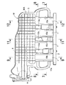
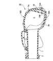
先ず、図1〜図3において、符号Mは自動車に搭載される4気筒エンジンE用の吸気マニフォルドを示す。この吸気マニフォルドMは、図1で左右方向を長手方向とする箱形をなしており、その長手方向に沿う一側壁には、略水平姿勢で並列する4本の吸気分配管1,1…が形成され、これら吸気分配管1,1…の下流端には、これらを相互に一体に連結する共通の取り付けフランジ2が一体に形成される。この取り付けフランジ4は、エンジンEに複数のボルトにより結合されるようになっている。この吸気マニフォルドMは、図2に示すように、自動車のエンジンルームR内に収容される場合、ボンネットBの下面に近接するようにエンジンルームR内の上部に配置される。
First, in FIG. 1 to FIG. 3, a symbol M indicates an intake manifold for a four-cylinder engine E mounted on an automobile. The intake manifold M has a box shape whose longitudinal direction is the left-right direction in FIG. 1, and four
また吸気マニフォルドMの、4本の吸気分配管1,1…の配列方向に沿う一端壁には吸気入口管3が一体に形成され、この吸気入口管3の上流には方形の取り付けフランジ4が一体に形成される。この取り付けフランジ4にはスロットルボディTが複数のボルトにより取り付けられるようになっている。
Further, an
さらに吸気マニフォルドMの内部は、図4〜図9に示すように、吸気入口管3と4本の吸気分配管1,1…との間を連通するサージ室5になっており、このサージ室5には、吸気入口管3のサージ室5への開口端の、吸気分配管1,1…側の端縁から吸気分配管1,1…の配列方向に延びてサージ室5の略中央部に達する吸気案内壁6が配設される。この吸気案内壁6は、図4〜図6に明示するように、サージ室5内方に向うにつれて吸気分配管1,1…から離れるよう吸気入口管3の軸線Xに対して僅かに傾斜している。また吸気案内壁6の、吸気分配管1,1…と反対側の一側面は、吸気入口管3の内周面に連なる平滑面6aに形成される。
Further, the inside of the intake manifold M is a
而して、エンジンの吸気作用に伴ない吸気入口管3に流入した空気は、図4及び図6に矢印D1で示すように、吸気入口管3の内面に連なる吸気案内壁6の平滑面6aによりスムーズに誘導されることにより、圧力損失することなくサージ室5の中央部に到達することができる。したがって、吸気入口管3と、並列する4本の吸気分配管1,1…との各間の距離の長短に拘らず、上記空気は、図4及び図6に矢印D2で示すように、サージ室5の中央部から4本の吸気分配管1,1…へと略均等に分配されることになり、エンジンEの各気筒の吸気効率を高め、エンジン出力の向上に寄与し得る。
Thus, the air that flows into the
また図6及び図9及び図10に示すように、吸気案内壁6の、吸気分配管1,1…側の他側面6bには、相互に間隔を置いて平行に並ぶ上下方向の複数のリブ7,7…を残して、複数の肉抜き凹部8,8…が形成される。吸気案内壁6の、吸気入口管3側の端部には、吸気案内壁6と直交するように延びる補強壁9が一体に連設される。
Further, as shown in FIGS. 6, 9, and 10, on the
而して、複数の肉抜き凹部8,8…により吸気案内壁6の薄肉化が図られると共に、複数のリブ7,7…により吸気案内壁6剛性の強化を図ることができ、サージ室5での吸気圧力の脈動に起因する吸気案内壁6の振動騒音の発生を防ぐことができる。しかも吸気案内壁6の吸気分配管1,1…側の他側面6bは、空気流の誘導には殆ど関与しないから、その他側面6bに形成されたリブ7,7…及び肉抜き凹部8,8…は殆ど吸気抵抗とはならない。かくして、吸気案内壁6に良好な吸気案内機能を発揮させつゝ、吸気案内壁の薄肉化と剛性確保の両方を満足させることができる。
Thus, the
図4〜図9に示すように、吸気マニフォルドMの内部には、さらに、サージ室5に連通路12を介して連通するレゾネータ室10が設けられる。このレゾネータ室10は、前記4本の吸気分配管1,1…の相互間に画成される三つのレゾネータ小室10b〜10dと、吸気分配管1,1…群の両外側部に形成される二つのレゾネータ小室10a,10eと、合計五つのレゾネータ小室10a〜10eを相互に連通すべく、吸気分配管1,1…の上面を横切るように延びるように配置される上下に偏平な連通室11とよりなっており、この連通室11の長手方向一端部が前記連通路12を介してサージ室5の中央部に連通される。その際、レゾネータ小室10a〜10eは、その容積を極力大きく確保すべく、隣接する吸気分配管1,1…の下面より下方へ突出するようにして形成される。但し、望ましくは、レゾネータ小室10a〜10eの吸気分配管1,1…下面よりの突出は、サージ室11の下面の高さより上方位置に止める。
As shown in FIGS. 4 to 9, a
このように、レゾネータ室10の主要部をなす複数のレゾネータ小室10a〜10eは、複数の吸気分配管1,1…の相互間のデッドスペースのみならず、吸気分配管1,1…群の両外側のデッドスペース及びそれらの下方のデッドスペースを利用して形成されるので、レゾネータ室10に充分な容積を付与し得ると共に、レゾネータ室10の吸気マニフォルドM下面への不必要な突出を防ぐことができ、レゾネータ室10による吸気マニフォルドMの大型化を防ぐことができる。また複数のレゾネータ小室10a〜10eの相互間を連通する連通室11は、吸気分配管1,1…の上面を横切るように延びる上下に偏平な形状をなしているので、この連通室11も吸気マニフォルドM上面からの突出を最小限に抑えながら、レゾネータ室10の容積拡張に寄与すると共に、レゾネータ室10による吸気マニフォルドMの大型化を防ぎ、そのコンパクト化を図ることができる。また複数のレゾネータ小室10a〜10eの相互間を連通する連通室11は、吸気分配管1,1…の上面を横切るように延びる上下に偏平な形状をなしているので、この連通室11も吸気マニフォルドM上面からの突出を最小限に抑えながら、レゾネータ室10の容積拡張に寄与すると共に、レゾネータ室10による吸気マニフォルドMの大型化を防ぎ、そのコンパクト化を図ることができる。こうして充分な容積を得たレゾネータ室10は、エンジンEの運転中、共鳴作用により、サージ室5に発生する吸気騒音の所定の周波数帯域での消音を可能にすると共に、エンジンのトルク増加に寄与する。しかも、上記のようにコンパクトに構成されたレゾネータ付き吸気マニフォルドMは、自動車の狭小なエンジンルームR内上部に配置されても、エンジンEやボンネットBとの干渉を回避することができるので、小型自動車用に特に有効である。
As described above, the plurality of resonator
同じく図4〜図9において、上記吸気マニフォルドMは、それぞれ合成樹脂をもって個別に成形される下部の第1マニフォルド半体MAと上部の第2マニフォルド半体MBとで構成され、この両マニフォルド半体MA、MBは、それらの互いに対向する接合面15A,15Bを振動摩擦溶着することにより接合されるようになっている。
4 to 9, the intake manifold M is composed of a lower first manifold half MA and an upper second manifold half MB, which are individually molded with synthetic resin, and both manifold halves. MA and MB are joined together by vibration friction welding their
その第1マニフォルド半体MAには、取り付けフランジ2と、吸気入口管3の一半部3Aと、サージ室5の一半部5Aと、吸気案内壁6の一半部6Aと、吸気分配管1,1…群と、取り付けフランジ2と、レゾネータ小室10a〜10e群と、連通路12の一半部となる浅い第1凹溝12Aとが備えられる。一方、第2マニフォルド半体MBには、吸気入口管3の他半部3Bと、サージ室5の他半部5Bと、吸気案内壁6の他半部6Bと、連通室11と、連通路12の他半部となる深い第2凹溝12Bと、補強壁9の他半部9Bとが備えられる。
The first manifold half MA includes a mounting
第1マニフォルド半体MAの下面には、サージ室5、4本の吸気分配管1,1…及び中間の3つレゾネータ小室10b〜10dに囲まれる3つの凹部13a〜13c が形成され、そのうちの吸気入口管3側で隣接する2つの凹部13a,13bの天井壁は、これら凹部13a,13bに隣接する2本の吸気分配管1,1の管壁に連続して平坦壁16を構成し、この平坦壁16に前記浅い凹溝12Aが形成される。
On the lower surface of the first manifold half MA, there are formed three
吸気案内壁6の一半部6Aは高さが低く形成され、同他半部6Bは高さが高く形成され、その他半部6Bに前記複数のリブ7,7…及び肉抜き凹部8,8…が設けられ、これら肉抜き凹部8,8…の下端は、該他半部6Bの下端面、即ち接合面15Bの手前で終わっている(特に図9、図10参照)。したがって、第1及び第2マニフォルド半体MA、MB相互の溶着と同時に吸気案内壁6の一半部6A及び他半部6B相互の溶着を可能して、強固な吸気案内壁6を構成し得ると共に、これにより吸気マニフォルドMの剛性強化を図ることができ、しかも吸気案内壁6の一半部6A及び他半部6Bの溶着面積の、肉抜き凹部8,8…による減少を回避して、両半部6A,6B相互の溶着強度を高めることができる。
One
第1及び第2マニフォルド半体MA、MBの互いに対向する接合面15A,15Bには、それぞれ吸気入口管3の一部と、サージ室5及びレゾネータ室10全体を囲繞する無端状の第1溶着ビード20A,20Bと、この第1溶着ビード20A,20Bからレゾネータ室10及び連通路12の一側壁に沿って延びる有端の第2溶着ビード21A,21Bと、第1溶着ビード20A,20Bから連通路12の他側壁に沿って延びる有端の第3溶着ビード22A,22Bと、この第3溶着ビード22A,22Bの、第1溶着ビード20A,20Bとの近接部から補強壁9及び吸気案内壁6に沿って延びる有端の第4ビード部23A,23Bとが形成される。
The first and second manifold halves MA and MB face each other on the
また第2マニフォルド半体MBの接合面15Bには、第1〜第4溶着ビード20B〜23Bの幅方向両側に溝24,24を挟んで起立する一対の規制壁25,25(図7参照)が形成される。
Further, on the
図4及び図5において、第1及び第2マニフォルド半体MA、MBの第2〜第4溶着ビード21A〜23A;21B〜23Bの端部21Ae〜23Ae;21Be〜23Beの横幅は、他の主要部の横幅より広く設定される。
4 and 5, the lateral widths of the end portions 21Ae to 23Ae; 21Be to 23Be of the second to
また第1マニフォルド半体MAの前記3つの凹部13a〜13cのうち、前記平坦壁16の形成に関わらない一つの凹部13aの天井壁16の上面は、第1マニフォルド半体MA側の接合面に連続しており、この凹部13aの天井壁16の上面に、有端の第2溶着ビード21Aの中間部と協働して閉じたロ字状の溶着ビードを構成する補強溶着ビード27Aが形成される。これに対応して、第2マニフォルド半体MBの接合面15Bにも補強溶着ビード27Bが形成されると共に、これを囲むように前記規制壁の25の一部が延長される。
Of the three
図8及び図11に示すように、第1及び第2マニフォルド半体MA、MBの接合面15A,15Bの溶着に当たっては、第1マニフォルド半体MAを、その接合面15Aを上向きにして支持台30上に載置し、その接合面15Aの溶着ビード20A〜22A,27Aに、第2マニフォルド半体MBの接合面15Bの溶着ビード20B〜22B,27Bを重ね合わせ、この第2マニフォルド半体MBを上方から押させる押え振動治具31を、吸気マニフォルドMの長手方向に沿って振動させる。
As shown in FIGS. 8 and 11, when welding the
その際、支持台30は、第1マニフォルド半体MAの下面周囲を支承する通常のバックアップ部を備える他に、特に、略中央部に3つのバックアップ凸部30a〜30cを備えており、これらバックアップ凸部30a〜30cは、第1マニフォルド半体MA下面の、サージ室5、4本の吸気分配管1,1…及び中間の3つレゾネータ小室10b〜10dに囲まれて形成された前記3つの凹部13a〜13cに嵌合して、それらの天井面に当接するようになっている。したがって、押え振動治具31により第2マニフォルド半体MBを上方から押さえて振動させたとき、第1及び第2マニフォルド半体MA、MBの中央部の撓みを支持台30のバックアップ凸部30a〜30cにより防ぐことができるため、吸気マニフォルドM周囲の第1溶着ビード20A,20B相互間は勿論、中程の第2〜第4溶着ビード21A〜22A;21B〜22B相互間に均等に摩擦熱を発生させて、両者間を確実に溶着することができる。その溶着代は、第2マニフォルド半体MBの規制壁25が第1マニフォルド半体MAの接合面15Aに当接することにより規制され、またその溶着に伴ない発生するバリは、規制壁25と各溶着ビード間の溝24に収容される。
In this case, the
このように、第1マニフォルド半体MA下面の、サージ室5、4本の吸気分配管1,1…及び中間の3つレゾネータ小室10b〜10dに囲まれて形成された3つの凹部13a〜13cを、支持台30のバックアップ凸部30a〜30cの嵌合用凹部に利用するので、第1マニフォルド半体MAの中央部に、バックアップ凸部30a〜30cの嵌合のための専用の凹部を形成する必要がなく、したがって第1マニフォルド半体MAの本来の構造及び形状を変更することなく、支持台30による第1マニフォルド半体MAの略中央部の支承を強固に行うことができて、両マニフォルド半体MA、MB間に良好な溶着部を形成することができる。図示例の場合、特に、バックアップ凸部30a〜30cが嵌合する凹部13a〜13cは、第1マニフォルド半体MAの第2及び第3溶着ビード21A,22Aの略直下に位置することになるから、その第2及び第3溶着ビード21A,22A周辺部の撓みを強固に抑え、上下の第2及び第3溶着ビード21A,22A〜21B,22B相互の溶着を、より確実に行うことができる。
In this way, the three
また第1及び第2マニフォルド半体MA、MBの第2〜第4溶着ビード21A〜23A;21B〜23Bにおいて、それらの端部21Ae〜23Ae;21Be〜23Beの横幅は、他の主要部の横幅より広く設定されるので、第2〜第4溶着ビード21A〜23A;21B〜23Bの各端部21Ae〜23Ae;21Be〜23Beでは、溶着面積が拡張して、その溶着強度を高めることができる。
Further, in the second and
而して、吸気マニフォルドMの使用状態では、エンジンEの振動等により、特に、有端の第2〜第4溶着ビード21A〜23A;21B〜23Bの各端部の溶着部に集中応力が発生する傾向があるが、その集中応力による、第2〜第4溶着ビード21A〜23A;21B〜23Bの各端部の溶着部の剥離を確実に防ぐことができる。
Thus, when the intake manifold M is in use, concentrated stress is generated due to vibrations of the engine E, etc., particularly at the welded portions of the end portions of the second to
さらに、有端の第2〜第4溶着ビード21A〜23A;21B〜23Bのうち、最も長い第2溶着ビード21A,21Bの中間部には、第2溶着ビード21A,21Bと協働して閉じたロ字状の溶着ビードを構成する補強溶着ビード27A,27Bが連設されるので、補強溶着ビード27A,27B相互の溶着により、第2溶着ビード21A,21Bの中間部相互の溶着強度が増強されることになり、第2溶着ビード21A,21Bの中間部の溶着部の、振動による剥離をも確実に防ぐことができる。
Further, among the second to
しかも、第1マニフォルド半体MA側の補強溶着ビード27Aは、一部のバックアップ凸部30cが嵌合する凹部13cの天井壁14を利用して、その上面に形成されるので、バックアップ凸部30cが嵌合する凹部13cは、補強溶着ビード27Aの略直下に位置することになるから、その補強溶着ビード27A周りの撓みを強固に抑え、上下の補強溶着ビード27A,27B相互の溶着を、より確実に行うことができる。
Moreover, the reinforcing
図5及び図12に示すように、第2マニフォルド半体MBには、サージ室5の、吸気入口管3から離れた角部に、吸気入口管3から離れた最外側の吸気分配管1への空気の流れをスムーズに誘導する断面円弧状の案内壁33が設けられる。
As shown in FIGS. 5 and 12, the second manifold half MB is connected to the corner of the
本発明は上記実施形態に限定されるものではなく、その要旨を逸脱しない範囲で種々の設計変更が可能である。例えば、本発明は、上記4気筒以外の多気筒エンジン用にも適用することができる。また吸気案内壁6の一半部6A及び他半部6Bを略同じ高さに形成して、その両者の他側面6bにリブ7及び肉抜き凹部8を形成することもできる。
The present invention is not limited to the above-described embodiment, and various design changes can be made without departing from the gist thereof. For example, the present invention can be applied to a multi-cylinder engine other than the above-described four cylinders. Alternatively, the
M・・・・・吸気マニフォルド
MA・・・・第1マニフォルド半体
MB・・・・第2マニフォルド半体
1・・・・・吸気分配管
3・・・・・吸気入口管
5・・・・・サージ室
5A・・・・サージ室の一半部
5B・・・・サージ室の他半部
10・・・・レゾネータ室
10b〜10d・・・レゾネータ小室
12・・・・連通路
12A・・・第1凹溝
12B・・・第2凹溝
13a〜13c・・・凹部
15A・・・第1マニフォルド半体側の接合面
15B・・・第2マニフォルド半体側の接合面
21A・・・下部溶着ビード(第1マニフォルド半体側の第2溶着ビード)
21B・・・上部溶着ビード(第2マニフォルド半体側の第2溶着ビード)
27A・・・下部補強溶着ビード
27B・・・上部補強溶着ビード
30・・・・支持台
30a〜30c・・・バックアップ凸部
M ... Intake manifold MA ... First manifold half MB ... Second
21B ... Upper weld bead (second weld bead on the second manifold half)
27A ... Lower
Claims (2)
隣り合う吸気分配管(1)の間に、前記レゾネータ室(10)の一部となるレゾネータ小室(10b〜10d)を形成したものにおいて、
前記複数の吸気分配管(1)、前記サージ室(5)の一半部(5A)、前記レゾネータ小室(10b〜10d)、及び前記連通路(12)の一半部となる第1凹溝(12A)を有する合成樹脂製の第1マニフォルド半体(MA)と、前記サージ室(5)の他半部(5B)、及び前記連通路(12)の他半部となる第2凹溝(12B)を有する合成樹脂製の第2マニフォルド半体(MB)との相対向する接合面(15A,15B)を相互に溶着してなり、
前記第1マニフォルド半体(MA)の下面には、前記サージ室(5)、前記複数の吸気分配管(1)及び前記レゾネータ小室(10b〜10d)に囲まれる凹部(13a〜13c )が形成されていて、この凹部(13a〜13c )を、前記第1及び第2マニフォルド半体(MA、MB)相互の溶着時、前記第1マニフォルド半体(MA)を支持する支持台(30)のバックアップ凸部(30a〜30c)の嵌合用としたことを特徴とするエンジン用吸気マニフォルド。 A plurality of intake pipes (1) arranged in parallel in a substantially horizontal posture are provided on one side wall, and an intake inlet pipe (3) is provided on the other wall, and an intake inlet pipe (3) and an intake pipe (1) are provided inside. An intake manifold for an engine comprising a surge chamber (5) communicating with each other and a resonator chamber (10) communicating with the surge chamber (5) via a communication passage (12),
In what formed the resonator small chamber (10b-10d) used as a part of said resonator chamber (10) between adjacent intake pipes (1) ,
A plurality of intake pipes (1), a half (5A) of the surge chamber (5), a resonator chamber (10b to 10d), and a first groove (12A) serving as a half of the communication passage (12) ) Having a first manifold half (MA) made of synthetic resin, the other half (5B) of the surge chamber (5), and the second groove (12B) serving as the other half of the communication path (12). ) And the second manifold halves (MB) made of synthetic resin having mutually opposite joint surfaces (15A, 15B)
On the lower surface of the first manifold half (MA), recesses (13a-13c) surrounded by the surge chamber (5), the plurality of intake pipes (1), and the resonator small chambers (10b-10d) are formed. The recesses (13a to 13c) are formed on the support base (30) for supporting the first manifold half (MA) when the first and second manifold halves (MA, MB) are welded to each other. engine intake Maniforu de, characterized in that it has a for fitting of the backup protrusions (30 a to 30 c).
前記第1及び第2マニフォルド半体(MA、MB)の両接合面(15A,15B)には、前記サージ室(5)及び前記レゾネータ室(10)間を区画するように相互に溶着される下部溶着ビード(21A)及び上部溶着ビード(21B)をそれぞれ形成し、また前記凹部(13a〜13c )の天井壁(14)に、前記下部溶着ビード(21A)に連続する下部補強溶着ビード(27A)を形成すると共に、前記上部溶着ビード(21B)に連続して前記下部補強溶着ビード(27A)と溶着される上部補強溶着ビード(27B)を前記第2マニフォルド半体(MB)に形成したことを特徴とするエンジン用吸気マニフォルド。 The intake manifold for an engine according to claim 1 ,
Said first and second manifold halves (MA, MB) the joining surfaces of (15A, 15B), the are welded to each other so as to define between the surge chamber (5) and the resonator chamber (10) A lower weld bead (21A) and an upper weld bead (21B) are respectively formed, and a lower reinforcing weld bead (27A) continuous to the lower weld bead (21A) is formed on the ceiling wall (14) of the recesses (13a to 13c). ) to form a, that the upper reinforcing weld beads continuously to the upper weld bead (21B) is welded to the lower reinforcing weld bead (27A) (27B) formed in the second manifold half body (MB) An intake manifold for engines that features
Priority Applications (1)
| Application Number | Priority Date | Filing Date | Title |
|---|---|---|---|
| JP2011199462A JP5243586B2 (en) | 2011-09-13 | 2011-09-13 | Engine intake manifold |
Applications Claiming Priority (1)
| Application Number | Priority Date | Filing Date | Title |
|---|---|---|---|
| JP2011199462A JP5243586B2 (en) | 2011-09-13 | 2011-09-13 | Engine intake manifold |
Related Parent Applications (1)
| Application Number | Title | Priority Date | Filing Date |
|---|---|---|---|
| JP2007262248A Division JP4828500B2 (en) | 2007-10-05 | 2007-10-05 | Engine intake manifold |
Publications (3)
| Publication Number | Publication Date |
|---|---|
| JP2011247274A JP2011247274A (en) | 2011-12-08 |
| JP2011247274A5 JP2011247274A5 (en) | 2012-07-19 |
| JP5243586B2 true JP5243586B2 (en) | 2013-07-24 |
Family
ID=45412796
Family Applications (1)
| Application Number | Title | Priority Date | Filing Date |
|---|---|---|---|
| JP2011199462A Expired - Fee Related JP5243586B2 (en) | 2011-09-13 | 2011-09-13 | Engine intake manifold |
Country Status (1)
| Country | Link |
|---|---|
| JP (1) | JP5243586B2 (en) |
Families Citing this family (2)
| Publication number | Priority date | Publication date | Assignee | Title |
|---|---|---|---|---|
| JP6142477B2 (en) * | 2012-07-31 | 2017-06-07 | アイシン精機株式会社 | Intake manifold |
| JP6656973B2 (en) * | 2016-03-24 | 2020-03-04 | トヨタ紡織株式会社 | Intake manifold |
Family Cites Families (5)
| Publication number | Priority date | Publication date | Assignee | Title |
|---|---|---|---|---|
| JPS5949361A (en) * | 1982-09-14 | 1984-03-21 | Nippon Denso Co Ltd | Air-intake silencer in internal-combustion engine |
| DE4216255A1 (en) * | 1992-05-16 | 1993-11-18 | Mann & Hummel Filter | Intake pipe and process for its manufacture |
| JPH10205401A (en) * | 1997-01-21 | 1998-08-04 | Toyota Motor Corp | Intake manifold with resonator |
| JP2003328883A (en) * | 2002-05-09 | 2003-11-19 | Mitsubishi Electric Corp | Intake device with resonator |
| JP4960775B2 (en) * | 2007-06-28 | 2012-06-27 | 株式会社マーレ フィルターシステムズ | Intake manifold for internal combustion engine |
-
2011
- 2011-09-13 JP JP2011199462A patent/JP5243586B2/en not_active Expired - Fee Related
Also Published As
| Publication number | Publication date |
|---|---|
| JP2011247274A (en) | 2011-12-08 |
Similar Documents
| Publication | Publication Date | Title |
|---|---|---|
| JP4837646B2 (en) | Engine intake manifold | |
| JP5610890B2 (en) | Intake system parts | |
| JP4960775B2 (en) | Intake manifold for internal combustion engine | |
| JP2008184939A (en) | Resin-made intake manifold | |
| JP5243586B2 (en) | Engine intake manifold | |
| JP6160248B2 (en) | Intake device | |
| JP5345966B2 (en) | Exhaust manifold | |
| JP2004124883A (en) | Resonance prevention structure of engine exhaust silencer | |
| JP6565657B2 (en) | Intake device and manufacturing method thereof | |
| JP4828500B2 (en) | Engine intake manifold | |
| JP5934150B2 (en) | Silencer | |
| JP2011247274A5 (en) | ||
| JP5357293B2 (en) | Intake manifold for internal combustion engine | |
| JP6656973B2 (en) | Intake manifold | |
| JP2015014210A (en) | Muffler | |
| JP2012036808A (en) | Duct | |
| JP4422557B2 (en) | Intake manifold | |
| JP6215596B2 (en) | Resin intake manifold | |
| JP3619441B2 (en) | Intake manifold | |
| JP6092639B2 (en) | Silencer | |
| JP2014047738A (en) | Resin intake manifold | |
| JP6660343B2 (en) | Silencer | |
| JP2005098287A (en) | Fuel delivery pipe | |
| JP5591014B2 (en) | duct | |
| JP2005315168A (en) | Muffler separator |
Legal Events
| Date | Code | Title | Description |
|---|---|---|---|
| A521 | Request for written amendment filed |
Free format text: JAPANESE INTERMEDIATE CODE: A523 Effective date: 20111011 |
|
| A621 | Written request for application examination |
Free format text: JAPANESE INTERMEDIATE CODE: A621 Effective date: 20111011 |
|
| A521 | Request for written amendment filed |
Free format text: JAPANESE INTERMEDIATE CODE: A523 Effective date: 20120606 |
|
| A131 | Notification of reasons for refusal |
Free format text: JAPANESE INTERMEDIATE CODE: A131 Effective date: 20120905 |
|
| A521 | Request for written amendment filed |
Free format text: JAPANESE INTERMEDIATE CODE: A523 Effective date: 20121105 |
|
| TRDD | Decision of grant or rejection written | ||
| A01 | Written decision to grant a patent or to grant a registration (utility model) |
Free format text: JAPANESE INTERMEDIATE CODE: A01 Effective date: 20130327 |
|
| A61 | First payment of annual fees (during grant procedure) |
Free format text: JAPANESE INTERMEDIATE CODE: A61 Effective date: 20130404 |
|
| FPAY | Renewal fee payment (event date is renewal date of database) |
Free format text: PAYMENT UNTIL: 20160412 Year of fee payment: 3 |
|
| R150 | Certificate of patent or registration of utility model |
Free format text: JAPANESE INTERMEDIATE CODE: R150 Ref document number: 5243586 Country of ref document: JP Free format text: JAPANESE INTERMEDIATE CODE: R150 |
|
| R250 | Receipt of annual fees |
Free format text: JAPANESE INTERMEDIATE CODE: R250 |
|
| R250 | Receipt of annual fees |
Free format text: JAPANESE INTERMEDIATE CODE: R250 |
|
| R250 | Receipt of annual fees |
Free format text: JAPANESE INTERMEDIATE CODE: R250 |
|
| R250 | Receipt of annual fees |
Free format text: JAPANESE INTERMEDIATE CODE: R250 |
|
| R250 | Receipt of annual fees |
Free format text: JAPANESE INTERMEDIATE CODE: R250 |
|
| R250 | Receipt of annual fees |
Free format text: JAPANESE INTERMEDIATE CODE: R250 |
|
| S111 | Request for change of ownership or part of ownership |
Free format text: JAPANESE INTERMEDIATE CODE: R313111 |
|
| R350 | Written notification of registration of transfer |
Free format text: JAPANESE INTERMEDIATE CODE: R350 |
|
| LAPS | Cancellation because of no payment of annual fees |