WO2014192095A1 - 乗り物用座席 - Google Patents
乗り物用座席 Download PDFInfo
- Publication number
- WO2014192095A1 WO2014192095A1 PCT/JP2013/064880 JP2013064880W WO2014192095A1 WO 2014192095 A1 WO2014192095 A1 WO 2014192095A1 JP 2013064880 W JP2013064880 W JP 2013064880W WO 2014192095 A1 WO2014192095 A1 WO 2014192095A1
- Authority
- WO
- WIPO (PCT)
- Prior art keywords
- seat
- cross member
- frame
- seat back
- vehicle
- Prior art date
- Legal status (The legal status is an assumption and is not a legal conclusion. Google has not performed a legal analysis and makes no representation as to the accuracy of the status listed.)
- Ceased
Links
Images



Classifications
-
- B—PERFORMING OPERATIONS; TRANSPORTING
- B60—VEHICLES IN GENERAL
- B60N—SEATS SPECIALLY ADAPTED FOR VEHICLES; VEHICLE PASSENGER ACCOMMODATION NOT OTHERWISE PROVIDED FOR
- B60N2/00—Seats specially adapted for vehicles; Arrangement or mounting of seats in vehicles
- B60N2/24—Seats specially adapted for vehicles; Arrangement or mounting of seats in vehicles for particular purposes or particular vehicles
- B60N2/26—Seats specially adapted for vehicles; Arrangement or mounting of seats in vehicles for particular purposes or particular vehicles for children
- B60N2/28—Seats readily mountable on, and dismountable from, existing seats or other parts of the vehicle
- B60N2/2887—Fixation to a transversal anchorage bar, e.g. isofix
- B60N2/2893—Fixation to a transversal anchorage bar, e.g. isofix coupled to the seat sub-frame
-
- B—PERFORMING OPERATIONS; TRANSPORTING
- B60—VEHICLES IN GENERAL
- B60N—SEATS SPECIALLY ADAPTED FOR VEHICLES; VEHICLE PASSENGER ACCOMMODATION NOT OTHERWISE PROVIDED FOR
- B60N2/00—Seats specially adapted for vehicles; Arrangement or mounting of seats in vehicles
- B60N2/02—Seats specially adapted for vehicles; Arrangement or mounting of seats in vehicles the seat or part thereof being movable, e.g. adjustable
- B60N2/22—Seats specially adapted for vehicles; Arrangement or mounting of seats in vehicles the seat or part thereof being movable, e.g. adjustable the back-rest being adjustable
-
- B—PERFORMING OPERATIONS; TRANSPORTING
- B60—VEHICLES IN GENERAL
- B60N—SEATS SPECIALLY ADAPTED FOR VEHICLES; VEHICLE PASSENGER ACCOMMODATION NOT OTHERWISE PROVIDED FOR
- B60N2/00—Seats specially adapted for vehicles; Arrangement or mounting of seats in vehicles
- B60N2/68—Seat frames
-
- B—PERFORMING OPERATIONS; TRANSPORTING
- B60—VEHICLES IN GENERAL
- B60N—SEATS SPECIALLY ADAPTED FOR VEHICLES; VEHICLE PASSENGER ACCOMMODATION NOT OTHERWISE PROVIDED FOR
- B60N2/00—Seats specially adapted for vehicles; Arrangement or mounting of seats in vehicles
- B60N2/68—Seat frames
- B60N2/688—Particular seat belt attachment and guiding
-
- B—PERFORMING OPERATIONS; TRANSPORTING
- B60—VEHICLES IN GENERAL
- B60N—SEATS SPECIALLY ADAPTED FOR VEHICLES; VEHICLE PASSENGER ACCOMMODATION NOT OTHERWISE PROVIDED FOR
- B60N2205/00—General mechanical or structural details
- B60N2205/30—Seat or seat parts characterised by comprising plural parts or pieces
- B60N2205/35—Seat, bench or back-rests being split laterally in two or more parts
Definitions
- the present invention relates to a seat for use in a vehicle, for example, an automobile.
- Patent Document 1 proposes a vehicle seat in which first and second lean reinforcement frames are provided in a seat cushion frame and a seat back frame so as to divide them into left and right.
- first and second lean reinforcement frames are provided in a seat cushion frame and a seat back frame so as to divide them into left and right.
- the rear end portion of the seat cushion frame along the first lean reinforcement frame, the upper end portion of the seat back frame along the second lean reinforcement frame, and the end portion of the seat cushion frame are provided.
- a three-point seat belt connecting the buckle is provided, and the partition region of the seat cushion frame including the measuring portion partitioned by the first lean reinforcement frame is relatively set with respect to the partition region of the second lean reinforcement frame. It is easy to deform.
- the first lean reinforcement frame and the second lean reinforcement frame are connected via a reclining device, and the seat back frame can be rotated forward and backward.
- the lean reinforcement frame is provided on both the seat cushion frame and the seat back frame, so that the weight increases.
- the seat is a six-part split side of a so-called 6: 4 split seat
- the first lean reinforcement frame comes directly under the right buttock of the person sitting on the left side (left and right center side as an automobile). For this reason, it is necessary to cover with a cover so that the seat cushion does not get caught in the gear or the like of the reclining device, the thickness of the cushion portion becomes thin and the seating comfort is poor, and the manufacturing cost increases as much as the cover is required.
- An object of the present invention is to provide a vehicle seat that is lightweight, comfortable to sit, and capable of reducing manufacturing costs.
- the vehicle seat includes a seat cushion frame for two-seaters on the 60% side of the 6: 4 split seat, and first and second seat cushion frames for two-seaters on the 60% side of the 6: 4 split seat.
- a seat back frame a first seat back supported by the first seat back frame, a second seat back supported by the second seat back frame, and the seat cushion frame,
- a reclining device for holding the first and second seat back frames so as to be pivotable back and forth; and the first seat back frame and the second seat back frame in the first and second seat backs.
- a lean reinforcement frame provided between right and left compartments of the first and second seat backs, and the first and second seat back frames. Crosslinked to the lower end portion, and a lower cross member for supporting the lower end of the reinforcement reinforcement frame.
- the vehicle seat is light.
- the thickness of the cushion portion can be ensured, the sitting comfort of the vehicle seat can be improved.
- a cover for covering the reclining device is unnecessary, and the manufacturing cost of the vehicle seat can be remarkably reduced.
- the lower cross member includes an in lower cross member on the center side of the vehicle from the position where the lean reinforcement frame is disposed, and an out lower cross member which is not on the center side of the vehicle from the position where the lean reinforcement frame is disposed.
- the in-lower cross member may be higher in rigidity than the out-lower cross member.
- the rigidity of the out lower cross member that is not on the center side of the vehicle is lower than the rigidity of the in lower cross member on the center side of the vehicle than the lean reinforcement frame. For this reason, it is possible to absorb an impact caused by sudden acceleration or deceleration.
- the seat back on the center side of the vehicle of the first and second seat backs can be tilted forward to support the occupant's elbow and can be held at a predetermined angle by the reclining device. Also good.
- the seat back on the center side of the vehicle can be held in a standing state by the reclining device. For this reason, even if an impact is applied from the rear side of the vehicle seat due to a sudden movement of the load, it can sufficiently withstand. Therefore, a member for protecting the back of the vehicle seat is not required, and the cost of the vehicle seat can be reduced accordingly. Further, since the seat back can be held at an appropriate position by the reclining device, it is possible to appropriately cope with the posture of the occupant.
- the reclining device includes an outer reclining device and an inner reclining device, and the vehicle seat is supported by the rear cross member bridged between the outer reclining device and the inner reclining device, and the rear cross member.
- the base bracket and a buckle supported by the base bracket may be further provided, and the buckle may be attached to the base bracket before the base bracket is attached to the rear cross member.
- the buckle is attached in advance to the base bracket before the base bracket is attached to the rear cross member. For this reason, the assembly man-hour of the vehicle seat can be reduced.
- FIG. 1 is a perspective view of a vehicle seat according to an embodiment of the present invention.
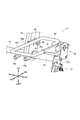
- FIG. 2 is a perspective view of the vehicle seat with the skin and cushion of FIG. 1 removed.
- FIG. 3 is a front view of a vehicle seat from which the safety belt retractor is omitted from FIG.
- FIG. 4 is a perspective view of a vehicle seat in a state where the seat back of FIG. 2 is armrested.
- FIG. 5 is a side view of the seat back in the state of FIG.
- the vehicle seat has a seat cushion frame for 60% of a 6: 4 split seat for two persons and the first and second seats for 60% of the 6: 4 split seat for two persons.
- a reclining device for holding the first and second seat back frames so as to be pivotable back and forth, and between the first seat back frame and the second seat back frame in the first and second seat backs.
- a lean reinforcement frame provided at left and right partition positions of the first and second seat backs, and the first and second seat back frames. Crosslinked to an end, and a lower cross member for supporting the lower end of the reinforcement reinforcement frame.
- the vehicle seat 1 is a 6: 4 divided seat divided into 6: 4 in the left and right directions LH and RH.
- the vehicle seat 1 includes a 40% single-seat seat 2 and a 60% double-seat seats 3 and 4.
- Two-seat seats 3 and 4 are a right seat (hereinafter referred to as a right seat) 3 arranged in the right direction RH, and a central seat (hereinafter referred to as a center seat) 4 arranged in the left direction LH. It becomes more.
- the right seat 3 includes a seat cushion 5, a seat back 6, and a headrest 7.
- the central seat 4 includes a seat cushion 8, a seat back 9, and a headrest 10.
- the single seat 2 includes a seat cushion 11, a seat back 12, and a headrest 13.
- a first buckle 14 that is a buckle is provided on the left side LH of the central seat 4.
- a safety belt 15 is provided on the right side RH of the central seat 4.
- the tongue plate 16 of the safety belt 15 engages with the first buckle 14 as shown by a two-dot chain line in FIG. 1 so that the shoulders and knees of a passenger (not shown) seated on the central seat 4 can be held.
- a third buckle 19 that is a buckle is provided on the left side LH of the right seat 3. By engaging a tongue plate (not shown) with the third buckle 19, the shoulder and knee of a passenger (not shown) seated on the right seat 3 can be held.
- a second buckle 17 that is a buckle is provided on the right side RH of the single-seat seat 2.
- a tongue plate (not shown) is engaged with the second buckle 17 so that the shoulders and knees of an occupant (not shown) seated on the single seat 2 can be held.
- recesses 18 formed so as not to interfere with fixed rails 20, 21 described later.
- the fixed rails 20 and 21 are fixed to the floor 50 of the automobile and are formed symmetrically. As shown in FIG. 2, the fixed rails 20 and 21 have a substantially U-shaped cross section with the tip facing inward, and are formed long in the front and rear FR and RR. Lock holes are formed in the fixed rails 20 and 21 at appropriate front-rear intervals.
- the movable rails 22 and 23 are engaged with the fixed rails 20 and 21. The movable rails 22 and 23 can move forward and backward FR and RR, and the movement can be locked by engaging the lock holes of the fixed rails 20 and 21 at appropriate positions.
- Such basic structures as the fixed rails 20 and 21 and the movable rails 22 and 23 are well-known techniques as disclosed in, for example, Japanese Patent Application Laid-Open No. 2004-243811.
- a front cross member 26 and a rear cross member 27 made of substantially straight pipes are bridged in the left and right directions LH and RH via the legs 24 and 25 on the movable rails 22 and 23.
- a seat cushion frame 28 made of a closed loop pipe is provided on the upper side UP of the front cross member 26 and the rear cross member 27 via a flip-up mechanism 30.
- the seat cushion frame 28 is provided with three spring bars 29 in the front-rear directions FR and RR.
- a side bracket 51 is held at an end of the right side RH of the rear cross member 27 via an outer reclining device 31 so as to be movable and lockable at an appropriate angle.
- the side bracket 51 is supported by welding on the side portion 39b of the seat back frame 39 which is a skeleton of the seat back 6.
- the seat back frame 39 includes a side portion 39b and an upper portion 39a having an inverted L shape with respect to the side portion 39b.
- a tower frame 52 which is a lean reinforcement frame, hangs down from the left LH end of the upper portion 39a.
- a cross pipe 40 is bridged between the side portion 39 b and the tower frame 52.
- an outer lower member 41 which is a lower cross member
- the outer lower member 41 has, for example, an outer diameter of 38.1 millimeters and a plate thickness of 2 millimeters.
- the lower cross member 42 which is a lower cross member, is bridged between the tower frame 52 and an arm 37a described later.
- the inner lower member 42 has, for example, an outer diameter of 42.7 millimeters and a plate thickness of 2 millimeters.
- the out lower cross member 41 may be bridged between the side bracket 51 and the arm 37a, and the in lower cross member 42 may cover the upper lower cross member 41 between the tower frame 52 and the arm 37a.
- An arm 37 a is held at an end of the left side LH of the rear cross member 27 via an inner reclining device 37 so as to be movable and lockable at an appropriate angle.
- An arm 47 is supported on the arm 37a by welding via a reclining device 38.
- the arm 47 is supported by welding on a side portion 46c of the seat back frame 46 which is a skeleton of the seat back 9.
- the seat back frame 46 includes an upper portion 46a, a side portion 46b on the tower frame 52 side, and a side portion 46c on the one-seat seat 2 side.
- a base bracket 36 is supported on the upper surface of the rear cross member 27 by welding.
- the base bracket 36 has an iron plate shape along the upper surface of the rear cross member 27.
- the third buckle 19, the tether anchor 33, the safety belt anchor 34, and the second ISO fix anchor 35 are attached to the base bracket 36 by welding in advance. ing.
- a first ISO fix anchor 32 is supported on the upper surface of the rear cross member 27 by welding.
- a retractor bracket 43 is supported by welding at the end of the left side LH of the cross pipe 40.
- a safety belt retractor 44 is fixed to the upper end portion of the retractor bracket 43.
- a belt guide 45 is supported on the upper portion 39 a of the seat back frame 39.
- the safety belt 15 shown in FIG. 1 is supported by a safety belt retractor 44 so as to be rewound, and passes through a belt guide 45 from the safety belt retractor 44.
- the upper portion 39a of the seat back frame 39 is provided with a stay holder 7a that supports a headrest stay (not shown) of the headrest 7.
- a stay holder 10 a that supports a headrest stay (not shown) of the headrest 10 is provided in the upper portion 46 a of the seat back frame 46.
- a second arm 48 is fixed to the side portion 46 b of the seat back frame 46.
- the second arm 48 is pivotally supported on the tower frame 52 by pins 49 so as to be vertically rotatable.
- the vehicle seat 1 is held by the two-seat seat cushion frame 28, the outer reclining device 31 and the inner reclining device 37 provided on the seat cushion frame 28 so as to be pivotable back and forth. And 60% seat back frames 39 and 46 of the quadrant.
- a tower frame 52 is provided in the left and right partition positions of the seat backs 6 and 9 in the seat back frames 39 and 46, and the lower cross members 41 and 42 bridged to the lower ends of the seat back frames 39 and 46 Supports the lower end.
- the inner lower cross member 42 on the center side of the vehicle (vehicle) from the position where the tower frame 52 is disposed has higher rigidity than the outer lower cross member 41 that is not on the center side. ing.
- the passenger's elbow (not shown) can be supported by rotating the seat back 9 on the center side of the automobile (vehicle) to the lower LWR so as to be tilted to the front FR. Further, the seat back 9 on the center side of the automobile (vehicle) can be held at a predetermined angle by the reclining device 38.
- the third buckle 19 is attached in advance to the base bracket 36 supported by the rear cross member 27 bridged between the reclining devices 31 and 37 before the base bracket 36 is attached to the rear cross member 27.
- the vehicle seat 1 is lightweight. Moreover, since the thickness of the cushion part which is not shown in figure can be ensured, the seating comfort of the vehicle seat 1 can be improved.
- the rigidity of the outer lower member 41 that is not on the center side of the automobile (vehicle) is lower than the rigidity of the inner lower member 42 on the center side of the automobile (vehicle) from the tower frame 52. For this reason, it is possible to absorb an impact caused by sudden acceleration or deceleration.
- the reclining devices 31 and 37 can hold the seat back 9 on the center side of the automobile (vehicle) in a standing state. For this reason, even if the vehicle seat 1 is given an impact from the rear RR due to a sudden movement of the luggage arranged on the rear RR of the vehicle seat 1, it can sufficiently withstand. For this reason, a member for protecting the back portion of the vehicle seat 1 becomes unnecessary, and the cost of the vehicle seat 1 can be reduced accordingly.
- the seat back frame 46 of the seat back 9 of the two-seat seat 4 can be held at an appropriate position by the reclining devices 31 and 37. For this reason, it can respond to a passenger
- the third buckle 19 is attached in advance to the base bracket 36 supported by the rear cross member 27 before the base bracket 36 is attached to the rear cross member 27. For this reason, the assembly man-hour of the vehicle seat 1 can be reduced.
- this invention is not limited to the said embodiment, A various deformation
- an example of an automobile is described as a vehicle, the present invention is not limited to this, and a seat such as an aircraft, a ship, or a vehicle may be used.
Landscapes
- Engineering & Computer Science (AREA)
- Aviation & Aerospace Engineering (AREA)
- Transportation (AREA)
- Mechanical Engineering (AREA)
- Health & Medical Sciences (AREA)
- Child & Adolescent Psychology (AREA)
- General Health & Medical Sciences (AREA)
- Seats For Vehicles (AREA)
Abstract
Description
Claims (4)
- 6:4分割シートの6割側の二人掛け用のシートクッションフレームと、
前記6:4分割シートの6割側の二人掛け用の第1及び第2のシートバックフレームと、
前記第1のシートバックフレームに支持された第1のシートバックと、
前記第2のシートバックフレームに支持された第2のシートバックと、
前記シートクッションフレームに設けられ、前記第1及び第2のシートバックフレームを前後回動自在に保持するリクライニング装置と、
前記第1及び第2のシートバック内で前記第1のシートバックフレームと前記第2のシートバックフレームとの間に設けられ、前記第1及び第2のシートバックの左右の区画位置に設けられたリーンホースメントフレームと、
前記第1及び第2のシートバックフレームの下端部に架橋され、前記リーンホースメントフレームの下端部を支持するロアクロスメンバーと、
を備えた乗り物用座席。 - 前記ロアクロスメンバーは、
前記リーンホースメントフレームの配設位置より前記乗り物の中央側のインロアクロスメンバーと、
前記リーンホースメントフレームの配設位置より前記乗り物の中央側で無いアウトロアクロスメンバーと、を含み、
前記インロアクロスメンバーは、前記アウトロアクロスメンバーよりも剛性が高い
請求項1に記載の乗り物用座席。 - 前記第1及び第2のシートバックのうち前記乗り物の中央側のシートバックは、前側に倒して乗員の肘をサポート可能であると共に、前記リクライニング装置により所定の角度に保持可能である
請求項1又は請求項2に記載の乗り物用座席。 - 前記リクライニング装置は、外側リクライニング装置と内側リクライニング装置とを含み、
前記乗り物用座席は、
前記外側リクライニング装置と前記内側リクライニング装置との間に架橋したリアクロスメンバーと、
前記リアクロスメンバーに支持されたベースブラケットと、
前記ベースブラケットに支持されたバックルと、をさらに備え、
前記バックルは、前記ベースブラケットの前記リアクロスメンバーへの取り付け前に前記ベースブラケットに取り付けられた
請求項1乃至請求項3の何れか1項に記載の乗り物用座席。
Priority Applications (3)
| Application Number | Priority Date | Filing Date | Title |
|---|---|---|---|
| PCT/JP2013/064880 WO2014192095A1 (ja) | 2013-05-29 | 2013-05-29 | 乗り物用座席 |
| CN201380076221.0A CN105392668B (zh) | 2013-05-29 | 2013-05-29 | 交通工具用座椅 |
| JP2015519539A JP6074500B2 (ja) | 2013-05-29 | 2013-05-29 | 乗り物用座席 |
Applications Claiming Priority (1)
| Application Number | Priority Date | Filing Date | Title |
|---|---|---|---|
| PCT/JP2013/064880 WO2014192095A1 (ja) | 2013-05-29 | 2013-05-29 | 乗り物用座席 |
Publications (1)
| Publication Number | Publication Date |
|---|---|
| WO2014192095A1 true WO2014192095A1 (ja) | 2014-12-04 |
Family
ID=51988168
Family Applications (1)
| Application Number | Title | Priority Date | Filing Date |
|---|---|---|---|
| PCT/JP2013/064880 Ceased WO2014192095A1 (ja) | 2013-05-29 | 2013-05-29 | 乗り物用座席 |
Country Status (3)
| Country | Link |
|---|---|
| JP (1) | JP6074500B2 (ja) |
| CN (1) | CN105392668B (ja) |
| WO (1) | WO2014192095A1 (ja) |
Cited By (5)
| Publication number | Priority date | Publication date | Assignee | Title |
|---|---|---|---|---|
| CN104924927A (zh) * | 2015-06-12 | 2015-09-23 | 苏州中航中振汽车饰件有限公司 | 多功能汽车三人座椅 |
| WO2018020734A1 (ja) * | 2016-07-29 | 2018-02-01 | テイ・エス テック株式会社 | 乗物用シート |
| EP3918953A3 (en) * | 2020-05-14 | 2022-02-16 | B/E Aerospace, Inc. | Seat usage prevention device |
| WO2022122485A1 (de) * | 2020-12-11 | 2022-06-16 | Bayerische Motoren Werke Aktiengesellschaft | Fahrzeugsitzanordnung |
| JP2023139958A (ja) * | 2022-03-22 | 2023-10-04 | 日本発條株式会社 | シートバックフレーム及び車両用シート |
Families Citing this family (1)
| Publication number | Priority date | Publication date | Assignee | Title |
|---|---|---|---|---|
| CN107472092A (zh) * | 2017-08-25 | 2017-12-15 | 浙江春风动力股份有限公司 | 全地形车及全地形车靠背结构 |
Citations (3)
| Publication number | Priority date | Publication date | Assignee | Title |
|---|---|---|---|---|
| JP2009101804A (ja) * | 2007-10-22 | 2009-05-14 | Nhk Spring Co Ltd | 車両用シート及び車両用シートの製造方法 |
| JP2010173482A (ja) * | 2009-01-29 | 2010-08-12 | Aisin Seiki Co Ltd | 車両用シートバックフレーム |
| JP2011046255A (ja) * | 2009-08-26 | 2011-03-10 | Honda Motor Co Ltd | 車体後部構造 |
Family Cites Families (9)
| Publication number | Priority date | Publication date | Assignee | Title |
|---|---|---|---|---|
| JPH0139476Y2 (ja) * | 1985-04-30 | 1989-11-27 | ||
| JPH0315742U (ja) * | 1989-06-30 | 1991-02-18 | ||
| JP3225840B2 (ja) * | 1996-05-12 | 2001-11-05 | トヨタ車体株式会社 | シートクッションフレーム |
| JP4041916B2 (ja) * | 1997-10-14 | 2008-02-06 | トヨタ紡織株式会社 | 車両用シート |
| JP2002199956A (ja) * | 2000-12-28 | 2002-07-16 | Tachi S Co Ltd | シート・クッション・フレーム |
| JP2002283891A (ja) * | 2001-03-23 | 2002-10-03 | Johnson Controls Automotive Systems Corp | 車両用シートにおけるシートバックフレーム |
| JP2003061777A (ja) * | 2001-08-27 | 2003-03-04 | Aisin Seiki Co Ltd | シートフレーム |
| JP4539435B2 (ja) * | 2005-05-17 | 2010-09-08 | トヨタ車体株式会社 | 車両用シート |
| US8132862B2 (en) * | 2009-01-29 | 2012-03-13 | Aisin Seiki Kabushiki Kaisha | Seat back frame for vehicle |
-
2013
- 2013-05-29 WO PCT/JP2013/064880 patent/WO2014192095A1/ja not_active Ceased
- 2013-05-29 JP JP2015519539A patent/JP6074500B2/ja not_active Expired - Fee Related
- 2013-05-29 CN CN201380076221.0A patent/CN105392668B/zh active Active
Patent Citations (3)
| Publication number | Priority date | Publication date | Assignee | Title |
|---|---|---|---|---|
| JP2009101804A (ja) * | 2007-10-22 | 2009-05-14 | Nhk Spring Co Ltd | 車両用シート及び車両用シートの製造方法 |
| JP2010173482A (ja) * | 2009-01-29 | 2010-08-12 | Aisin Seiki Co Ltd | 車両用シートバックフレーム |
| JP2011046255A (ja) * | 2009-08-26 | 2011-03-10 | Honda Motor Co Ltd | 車体後部構造 |
Cited By (12)
| Publication number | Priority date | Publication date | Assignee | Title |
|---|---|---|---|---|
| CN104924927A (zh) * | 2015-06-12 | 2015-09-23 | 苏州中航中振汽车饰件有限公司 | 多功能汽车三人座椅 |
| WO2018020734A1 (ja) * | 2016-07-29 | 2018-02-01 | テイ・エス テック株式会社 | 乗物用シート |
| JP2018016274A (ja) * | 2016-07-29 | 2018-02-01 | テイ・エス テック株式会社 | 乗物用シート |
| US11312268B2 (en) | 2016-07-29 | 2022-04-26 | Ts Tech Co., Ltd. | Vehicle seat |
| US11660987B2 (en) | 2016-07-29 | 2023-05-30 | Ts Tech Co., Ltd. | Vehicle seat |
| EP3918953A3 (en) * | 2020-05-14 | 2022-02-16 | B/E Aerospace, Inc. | Seat usage prevention device |
| US11571070B2 (en) | 2020-05-14 | 2023-02-07 | B/E Aerospace, Inc. | Seat usage prevention device |
| US11805915B2 (en) | 2020-05-14 | 2023-11-07 | B/E Aerospace, Inc. | Seat usage prevention device |
| WO2022122485A1 (de) * | 2020-12-11 | 2022-06-16 | Bayerische Motoren Werke Aktiengesellschaft | Fahrzeugsitzanordnung |
| US12330540B2 (en) | 2020-12-11 | 2025-06-17 | Bayerische Motoren Werke Aktiengesellschaft | Vehicle seat arrangement |
| JP2023139958A (ja) * | 2022-03-22 | 2023-10-04 | 日本発條株式会社 | シートバックフレーム及び車両用シート |
| JP7735211B2 (ja) | 2022-03-22 | 2025-09-08 | 日本発條株式会社 | シートバックフレーム及び車両用シート |
Also Published As
| Publication number | Publication date |
|---|---|
| JP6074500B2 (ja) | 2017-02-01 |
| CN105392668A (zh) | 2016-03-09 |
| CN105392668B (zh) | 2017-07-18 |
| JPWO2014192095A1 (ja) | 2017-02-23 |
Similar Documents
| Publication | Publication Date | Title |
|---|---|---|
| JP4743310B2 (ja) | 車両用シート装置 | |
| JP6074500B2 (ja) | 乗り物用座席 | |
| JP2015182683A (ja) | 車両 | |
| AU2012319835B2 (en) | Vehicle seat | |
| JP7014096B2 (ja) | 車両 | |
| JP2021049887A (ja) | 車載シート装置 | |
| JP2017136976A (ja) | 車体フロア構造 | |
| JP5584035B2 (ja) | 育児器具の座席構造および自動車用チャイルドシート | |
| JP2023060071A (ja) | シートクッションフレーム構造 | |
| JP6658304B2 (ja) | 乗物用シート | |
| JP5877184B2 (ja) | 車両用シート | |
| JP6324518B2 (ja) | 乗り物用シート及び乗り物用シートのフレーム構造体製造方法 | |
| JP2017197072A (ja) | 車両用シート | |
| JP2015145244A (ja) | 乗物用シート | |
| JP2013533161A (ja) | シートベルト配置 | |
| US20190070977A1 (en) | Vehicle seat | |
| JP7826925B2 (ja) | 乗物用シート | |
| JP6370112B2 (ja) | 自動車用リアシート | |
| JP2013154856A (ja) | ヘッドレスト装置及び車両用シート | |
| JP2023169658A (ja) | 多目的車両 | |
| JP2016188078A (ja) | 乗物用シート | |
| JP2025076835A (ja) | 車椅子、車椅子の固定構造 | |
| JP2023129634A (ja) | 乗物用シート | |
| JP2008054742A (ja) | シート着座補助装置 | |
| JP2015058014A (ja) | ヘッドレストの組付構造 |
Legal Events
| Date | Code | Title | Description |
|---|---|---|---|
| WWE | Wipo information: entry into national phase |
Ref document number: 201380076221.0 Country of ref document: CN |
|
| 121 | Ep: the epo has been informed by wipo that ep was designated in this application |
Ref document number: 13885542 Country of ref document: EP Kind code of ref document: A1 |
|
| ENP | Entry into the national phase |
Ref document number: 2015519539 Country of ref document: JP Kind code of ref document: A |
|
| NENP | Non-entry into the national phase |
Ref country code: DE |
|
| 122 | Ep: pct application non-entry in european phase |
Ref document number: 13885542 Country of ref document: EP Kind code of ref document: A1 |