WO2014185147A1 - トルクコンバータのロックアップ装置 - Google Patents
トルクコンバータのロックアップ装置 Download PDFInfo
- Publication number
- WO2014185147A1 WO2014185147A1 PCT/JP2014/057721 JP2014057721W WO2014185147A1 WO 2014185147 A1 WO2014185147 A1 WO 2014185147A1 JP 2014057721 W JP2014057721 W JP 2014057721W WO 2014185147 A1 WO2014185147 A1 WO 2014185147A1
- Authority
- WO
- WIPO (PCT)
- Prior art keywords
- coil spring
- small coil
- coil springs
- spring
- small
- Prior art date
- Legal status (The legal status is an assumption and is not a legal conclusion. Google has not performed a legal analysis and makes no representation as to the accuracy of the status listed.)
- Ceased
Links
Images


Classifications
-
- F—MECHANICAL ENGINEERING; LIGHTING; HEATING; WEAPONS; BLASTING
- F16—ENGINEERING ELEMENTS AND UNITS; GENERAL MEASURES FOR PRODUCING AND MAINTAINING EFFECTIVE FUNCTIONING OF MACHINES OR INSTALLATIONS; THERMAL INSULATION IN GENERAL
- F16H—GEARING
- F16H45/00—Combinations of fluid gearings for conveying rotary motion with couplings or clutches
- F16H45/02—Combinations of fluid gearings for conveying rotary motion with couplings or clutches with mechanical clutches for bridging a fluid gearing of the hydrokinetic type
-
- F—MECHANICAL ENGINEERING; LIGHTING; HEATING; WEAPONS; BLASTING
- F16—ENGINEERING ELEMENTS AND UNITS; GENERAL MEASURES FOR PRODUCING AND MAINTAINING EFFECTIVE FUNCTIONING OF MACHINES OR INSTALLATIONS; THERMAL INSULATION IN GENERAL
- F16F—SPRINGS; SHOCK-ABSORBERS; MEANS FOR DAMPING VIBRATION
- F16F15/00—Suppression of vibrations in systems; Means or arrangements for avoiding or reducing out-of-balance forces, e.g. due to motion
- F16F15/10—Suppression of vibrations in rotating systems by making use of members moving with the system
- F16F15/12—Suppression of vibrations in rotating systems by making use of members moving with the system using elastic members or friction-damping members, e.g. between a rotating shaft and a gyratory mass mounted thereon
- F16F15/121—Suppression of vibrations in rotating systems by making use of members moving with the system using elastic members or friction-damping members, e.g. between a rotating shaft and a gyratory mass mounted thereon using springs as elastic members, e.g. metallic springs
- F16F15/123—Wound springs
- F16F15/12353—Combinations of dampers, e.g. with multiple plates, multiple spring sets, i.e. complex configurations
- F16F15/1236—Combinations of dampers, e.g. with multiple plates, multiple spring sets, i.e. complex configurations resulting in a staged spring characteristic, e.g. with multiple intermediate plates
- F16F15/12366—Combinations of dampers, e.g. with multiple plates, multiple spring sets, i.e. complex configurations resulting in a staged spring characteristic, e.g. with multiple intermediate plates acting on multiple sets of springs
-
- F—MECHANICAL ENGINEERING; LIGHTING; HEATING; WEAPONS; BLASTING
- F16—ENGINEERING ELEMENTS AND UNITS; GENERAL MEASURES FOR PRODUCING AND MAINTAINING EFFECTIVE FUNCTIONING OF MACHINES OR INSTALLATIONS; THERMAL INSULATION IN GENERAL
- F16F—SPRINGS; SHOCK-ABSORBERS; MEANS FOR DAMPING VIBRATION
- F16F15/00—Suppression of vibrations in systems; Means or arrangements for avoiding or reducing out-of-balance forces, e.g. due to motion
- F16F15/10—Suppression of vibrations in rotating systems by making use of members moving with the system
- F16F15/12—Suppression of vibrations in rotating systems by making use of members moving with the system using elastic members or friction-damping members, e.g. between a rotating shaft and a gyratory mass mounted thereon
- F16F15/121—Suppression of vibrations in rotating systems by making use of members moving with the system using elastic members or friction-damping members, e.g. between a rotating shaft and a gyratory mass mounted thereon using springs as elastic members, e.g. metallic springs
- F16F15/123—Wound springs
- F16F15/12353—Combinations of dampers, e.g. with multiple plates, multiple spring sets, i.e. complex configurations
- F16F15/1236—Combinations of dampers, e.g. with multiple plates, multiple spring sets, i.e. complex configurations resulting in a staged spring characteristic, e.g. with multiple intermediate plates
- F16F15/12366—Combinations of dampers, e.g. with multiple plates, multiple spring sets, i.e. complex configurations resulting in a staged spring characteristic, e.g. with multiple intermediate plates acting on multiple sets of springs
- F16F15/12373—Combinations of dampers, e.g. with multiple plates, multiple spring sets, i.e. complex configurations resulting in a staged spring characteristic, e.g. with multiple intermediate plates acting on multiple sets of springs the sets of springs being arranged at substantially the same radius
-
- F—MECHANICAL ENGINEERING; LIGHTING; HEATING; WEAPONS; BLASTING
- F16—ENGINEERING ELEMENTS AND UNITS; GENERAL MEASURES FOR PRODUCING AND MAINTAINING EFFECTIVE FUNCTIONING OF MACHINES OR INSTALLATIONS; THERMAL INSULATION IN GENERAL
- F16H—GEARING
- F16H45/00—Combinations of fluid gearings for conveying rotary motion with couplings or clutches
- F16H45/02—Combinations of fluid gearings for conveying rotary motion with couplings or clutches with mechanical clutches for bridging a fluid gearing of the hydrokinetic type
- F16H2045/0205—Combinations of fluid gearings for conveying rotary motion with couplings or clutches with mechanical clutches for bridging a fluid gearing of the hydrokinetic type two chamber system, i.e. without a separated, closed chamber specially adapted for actuating a lock-up clutch
-
- F—MECHANICAL ENGINEERING; LIGHTING; HEATING; WEAPONS; BLASTING
- F16—ENGINEERING ELEMENTS AND UNITS; GENERAL MEASURES FOR PRODUCING AND MAINTAINING EFFECTIVE FUNCTIONING OF MACHINES OR INSTALLATIONS; THERMAL INSULATION IN GENERAL
- F16H—GEARING
- F16H45/00—Combinations of fluid gearings for conveying rotary motion with couplings or clutches
- F16H45/02—Combinations of fluid gearings for conveying rotary motion with couplings or clutches with mechanical clutches for bridging a fluid gearing of the hydrokinetic type
- F16H2045/0221—Combinations of fluid gearings for conveying rotary motion with couplings or clutches with mechanical clutches for bridging a fluid gearing of the hydrokinetic type with damping means
- F16H2045/0226—Combinations of fluid gearings for conveying rotary motion with couplings or clutches with mechanical clutches for bridging a fluid gearing of the hydrokinetic type with damping means comprising two or more vibration dampers
-
- F—MECHANICAL ENGINEERING; LIGHTING; HEATING; WEAPONS; BLASTING
- F16—ENGINEERING ELEMENTS AND UNITS; GENERAL MEASURES FOR PRODUCING AND MAINTAINING EFFECTIVE FUNCTIONING OF MACHINES OR INSTALLATIONS; THERMAL INSULATION IN GENERAL
- F16H—GEARING
- F16H45/00—Combinations of fluid gearings for conveying rotary motion with couplings or clutches
- F16H45/02—Combinations of fluid gearings for conveying rotary motion with couplings or clutches with mechanical clutches for bridging a fluid gearing of the hydrokinetic type
- F16H2045/0221—Combinations of fluid gearings for conveying rotary motion with couplings or clutches with mechanical clutches for bridging a fluid gearing of the hydrokinetic type with damping means
- F16H2045/0226—Combinations of fluid gearings for conveying rotary motion with couplings or clutches with mechanical clutches for bridging a fluid gearing of the hydrokinetic type with damping means comprising two or more vibration dampers
- F16H2045/0231—Combinations of fluid gearings for conveying rotary motion with couplings or clutches with mechanical clutches for bridging a fluid gearing of the hydrokinetic type with damping means comprising two or more vibration dampers arranged in series
-
- F—MECHANICAL ENGINEERING; LIGHTING; HEATING; WEAPONS; BLASTING
- F16—ENGINEERING ELEMENTS AND UNITS; GENERAL MEASURES FOR PRODUCING AND MAINTAINING EFFECTIVE FUNCTIONING OF MACHINES OR INSTALLATIONS; THERMAL INSULATION IN GENERAL
- F16H—GEARING
- F16H45/00—Combinations of fluid gearings for conveying rotary motion with couplings or clutches
- F16H45/02—Combinations of fluid gearings for conveying rotary motion with couplings or clutches with mechanical clutches for bridging a fluid gearing of the hydrokinetic type
- F16H2045/0273—Combinations of fluid gearings for conveying rotary motion with couplings or clutches with mechanical clutches for bridging a fluid gearing of the hydrokinetic type characterised by the type of the friction surface of the lock-up clutch
- F16H2045/0278—Combinations of fluid gearings for conveying rotary motion with couplings or clutches with mechanical clutches for bridging a fluid gearing of the hydrokinetic type characterised by the type of the friction surface of the lock-up clutch comprising only two co-acting friction surfaces
Definitions
- the present invention relates to a torque converter lock-up device, and more particularly to a torque converter lock-up device for transmitting torque and absorbing and damping torsional vibrations.
- the torque converter is often provided with a lock-up device for transmitting torque directly from the front cover to the turbine.
- This lockup device has a piston, a drive plate, a plurality of coil springs, a driven plate, and a spring holder (see Patent Document 1).
- a plurality of large coil springs are arranged on the outer peripheral side and the inner peripheral side. Further, small coil springs having a shorter free length than the large coil springs on the inner peripheral side are arranged on the inner peripheral portions of the plurality of large coil springs on the inner peripheral side. With this configuration, multi-stage torsional characteristics are formed.
- a plurality of large coil springs are disposed on the outer peripheral side, and a plurality of large coil springs and a plurality of small coil springs are disposed on the inner peripheral side. Thereby, a three-stage torsion characteristic is formed.
- the axial thickness in the range from the central portion in the radial direction to the inner peripheral side is thicker than the axial thickness on the outer peripheral side.
- the axial thickness of the whole apparatus comprised from a torque converter and a lockup apparatus may become large.
- the lock-up device since the small coil spring is arranged on the inner peripheral portion of the large coil spring on the inner peripheral side, the diameter of the large coil spring on the inner peripheral side is large. Become. For this reason, the lock-up device has an increased axial thickness on the inner peripheral side. Further, when the diameter of the large coil spring on the inner peripheral side is increased, the radial size of the entire lockup device may be increased.
- the present invention has been made in view of the above problems, and an object of the present invention is to set the torsional characteristics of the lockup device in multiple stages and provide the entire device with the lockup device in the torque converter. This is to reduce the size.
- a lock-up device for a torque converter according to claim 1 is a device for transmitting torque and absorbing / attenuating torsional vibration.
- the lockup device includes an input rotation member, an output rotation member, a plurality of large coil springs, and a plurality of small coil springs.
- the output rotation member is disposed to be rotatable with respect to the input rotation member.
- the plurality of large coil springs are arranged side by side in the circumferential direction on the outer side in the radial direction. The large coil spring is compressed in the rotational direction by the relative rotation of the input rotating member and the output rotating member.
- Each of the plurality of small coil springs is set to have a shorter free length than the large coil spring.
- the small coil spring is movably disposed on the inner periphery of the large coil spring.
- the coil springs are compressed in the order of at least one of the plurality of large coil springs and the plurality of small coil springs by the relative rotation of the input rotation member and the output rotation member.
- this lockup device when the input rotating member and the output rotating member rotate relative to each other and, for example, a torsion angle is generated between the input rotating member and the output rotating member, a plurality of large coil springs are compressed. Thereby, the torsional rigidity in the first stage is formed. Next, when the torsional angle is equal to or greater than the predetermined first angle, any one of the plurality of large coil springs and the plurality of small coil springs is compressed. Thereby, the torsional rigidity of the second stage is formed in the torsional characteristics. Subsequently, when the twist angle becomes equal to or larger than the predetermined second angle, the plurality of large coil springs and the plurality of (all) small coil springs are compressed. Thereby, the torsional rigidity in the third stage is formed. Thus, in this lockup device, the torsional characteristics can be set in multiple stages.
- the plurality of large coil springs are arranged in the circumferential direction on the outer side in the radial direction, and each of the plurality of small coil springs is movably disposed on the inner peripheral portion of the large coil spring.
- a plurality of large coil springs and a plurality of small coil springs are arranged on the outer peripheral side where the axial thickness is small in the torque converter, so even if the lockup device is provided in the torque converter Compared with the prior art, the overall size of the apparatus can be reduced.
- the free lengths of the large coil springs arranged opposite to each other in the radial direction are the same. Moreover, the free length of the small coil spring arrange
- the free lengths of the small coil springs adjacent in the circumferential direction are different.
- the torsional characteristics can be set in multiple stages by setting the free lengths of the small coil springs adjacent in the circumferential direction to different lengths. Specifically, in this case, as the torsion angle increases, the torsional characteristics can be set in multiple stages by compressing the small coil springs in order from the small coil spring having the longer free length. Thus, in this lockup device, the torsional characteristics can be set in multiple stages without adding a coil spring. That is, it is possible to reduce the overall size of the device while setting the torsional characteristics of the lockup device in multiple stages.
- a lockup device for a torque converter is the lockup device according to the third aspect, wherein the plurality of small coil springs include a first small coil spring and a second small coil spring.
- the first small coil spring and the second small coil spring are arranged on the inner peripheral portion of the large coil spring so as to be adjacent to each other in the circumferential direction.
- the free length of the first small coil spring is different from the free length of the second small coil spring.
- the torsional characteristics can be set in multiple stages without adding a space for the coil spring. That is, it is possible to reduce the overall size of the device while setting the torsional characteristics of the lockup device in multiple stages.
- the plurality of small coil springs further include a third small coil spring.
- the first to third small coil springs are arranged on the inner periphery of the large coil spring in the order of the first small coil spring, the second small coil spring, and the third small coil spring in the circumferential direction.
- the free length of the first small coil spring is longer than the free length of either the second small coil spring or the third small coil spring.
- the free length of one of the second small coil spring and the third small coil spring is longer than the free length of the other of the second small coil spring and the third small coil spring.
- the twist angle becomes equal to or greater than the predetermined third angle
- the plurality of large coil springs and the plurality (all) of small coil springs are compressed.
- the torsional rigidity of the fourth stage is formed in the torsional characteristics.
- the torsional characteristics can be set in multiple stages without adding a space for the coil spring. That is, it is possible to reduce the overall size of the device while setting the torsional characteristics of the lockup device in multiple stages.
- a lockup device for a torque converter is the lockup device according to any one of the first to fifth aspects, wherein at least one bending point of a plurality of stages of torsional characteristics indicating a relationship between a torsion angle and torque.
- the rigidity ratio between the Nth torsional rigidity and the (N + 1) th torsional rigidity is set to 1.5 or more and 4.0 or less (N is a natural number).
- the multi-stage torsion characteristic is a characteristic formed by compressing at least one of the large coil spring and the small coil spring according to the torsion angle corresponding to the relative rotation between the input rotation member and the output rotation member. .
- the rigidity ratio between the Nth torsional rigidity and the (N + 1) th torsional rigidity is set to 1.5 or more and 4.0 or less at at least one bending point of a plurality of stages of torsional characteristics. Vibration that may occur when the bending point of the characteristic is exceeded, that is, vibration due to a difference in rigidity can be suppressed. Thus, in this lockup device, the vibration resulting from the coil spring can be reliably suppressed.
- a lockup device for a torque converter is the lockup device according to any one of the first to fifth aspects, further comprising a plurality of parallel coil springs.
- the plurality of parallel coil springs are arranged side by side in the circumferential direction inward in the radial direction from the large coil spring, and operate in parallel with the large coil spring. By the relative rotation of the input rotating member and the output rotating member, the coil springs are compressed in the order of at least one of the plurality of large coil springs, the plurality of small coil springs, and the plurality of parallel coil springs.
- This lockup device further includes a plurality of parallel coil springs on the inner peripheral side of the large coil spring, so that the number of stages of torsional characteristics can be further increased.
- a curve of torsional characteristics up to the maximum torque can be formed smoothly.
- a space is formed in a circumferential direction between the parallel coil spring and the output rotating member.
- a timing for operating the parallel coil spring is determined by forming a space between the parallel coil spring and the output rotating member. For this reason, the operation timing of the parallel coil spring can be easily set by changing the size of this space. That is, a desired torsion characteristic can be easily set.
- a lockup device for a torque converter is the lockup device according to the seventh or eighth aspect, wherein at least one bending point of a plurality of torsional characteristics indicating a relationship between a torsion angle and a torque is Nth.
- the rigidity ratio between the torsional rigidity and the (N + 1) th torsional rigidity is set to 1.5 or more and 4.0 or less (N is a natural number).
- the multistage torsional characteristics are obtained by compressing at least one of the large coil spring, the small coil spring, and the parallel coil spring according to the torsion angle corresponding to the relative rotation between the input rotating member and the output rotating member. It is a characteristic that is formed.
- the rigidity ratio between the Nth torsional rigidity and the (N + 1) th torsional rigidity is set to 1.5 or more and 4.0 or less at at least one bending point of a plurality of stages of torsional characteristics. Vibration that may occur when the bending point of the characteristic is exceeded, that is, vibration due to a difference in rigidity can be suppressed. Thus, in this lockup device, even if the number of stages of torsional characteristics is increased, vibration caused by the coil spring can be reliably suppressed.
- the torsional characteristics of the lockup device can be set in multiple stages, and the overall size of the device can be reduced when the lockup device is provided in the torque converter.
- FIG. 1 shows a schematic longitudinal sectional view of a torque converter 1 as an embodiment of the present invention.
- An engine (not shown) is arranged on the left side of FIG. 1, and a transmission (not shown) is arranged on the right side of FIG.
- the R1 direction in FIG. 1 indicates the forward rotation direction.
- OO shown in FIG. 1 is the rotational axis of the torque converter 1
- arrow R1 shown in FIG. 2 is the rotational direction of the engine
- arrow R2 is the opposite rotational direction.
- the torque converter 1 has a torque converter main body 2 and a lockup device 6.
- the torque converter main body 2 is mainly composed of a front cover 3, an impeller 4, a turbine 5, and the like.
- the configuration of the torque converter main body 2 is the same as the conventional one, and will be described briefly.
- the front cover 3 is a disk-shaped member connected to the crankshaft of the engine.
- the front cover 3 constitutes a hydraulic oil chamber of the torque converter 1 together with the impeller 4.
- the turbine 5 is disposed in the hydraulic oil chamber and opposed to the impeller 4 in the axial direction.
- An inner peripheral portion of the turbine 5 is connected to a turbine hub 11 described later.
- the turbine hub 11 is connected to a main drive shaft (not shown) of the transmission.
- the turbine hub 11 is a cylindrical member.
- the turbine hub 11 is composed of a boss 60 and a conical flange 61 formed on the outer peripheral surface thereof.
- Splines 62 are formed on the inner peripheral surface of the boss 60.
- the spline 62 is in spline engagement with the main drive shaft on the transmission side.
- an outer peripheral surface 63 is formed on the boss 60.
- the outer peripheral surface 63 is located on the axial engine side with respect to the flange 61.
- the lock-up device 6 is a device for absorbing and damping input torsional vibrations while mechanically transmitting torque from the front cover 3 to the turbine 5. That is, the lockup device 6 has a clutch function and a damper function. As shown in FIG. 1, the lockup device 6 is disposed in a space between the front cover 3 and the turbine 5.
- the lockup device 6 mainly includes a piston 8, a drive plate 9, a driven plate 10, and a plurality of torsion springs 12. These members constitute a damper mechanism 13 as a whole.
- the drive plate 9 functions as an input rotating member
- the driven plate 10 functions as an output rotating member
- the torsion spring 12 functions as an elastic member between the two members. Note that the piston 8 and the drive plate 9 may be considered to function as input rotating members.
- the input side member is composed of a piston 8 and a drive plate 9.
- the piston 8 is disposed so as to divide the space between the front cover 3 and the turbine 5 in the axial direction.
- the piston 8 is an annular and disk-shaped member, and is a member that can move in the axial direction by a change in hydraulic pressure in the torque converter 1.
- the piston 8 is disposed close to the axial transmission side of the front cover 3.
- the piston 8 has an annular friction connecting portion 15.
- the friction connecting portion 15 is provided on the outer peripheral side of the piston 8.
- the friction coupling portion 15 is formed in an annular and flat shape.
- the friction coupling portion 15 faces the annular and flat friction surface 3 a of the front cover 3.
- An annular friction facing 16 is mounted on the friction cover 15 on the front cover 3 side.
- a heat treatment such as gas soft nitriding is performed on the surface of the friction connecting portion 15 on the turbine 5 side.
- the outer peripheral side cylindrical part 17 extended in the axial direction transmission side is formed in the outer peripheral side of the piston 8. As shown in FIG. Further, an inner peripheral cylindrical portion 18 extending toward the axial transmission side is formed on the inner peripheral edge of the piston 8. The inner peripheral cylindrical portion 18 is supported in the radial direction by the outer peripheral surface 63 of the boss 60. Thereby, the piston 8 is movable in the axial direction and the rotational direction with respect to the turbine hub 11.
- the drive plate 9 is fixed to the piston 8 and holds the torsion spring 12 and functions as an input member for inputting torque to the torsion spring 12.
- the drive plate 9 is an annular plate member and is disposed on the axial transmission side (turbine 5 side) of the outer peripheral portion of the piston 8.
- the drive plate 9 is carbonitrided on the entire surface.
- the drive plate 9 includes an annular portion 25 on the inner peripheral side, a spring support portion 26 on the outer peripheral side, a first spring contact portion 40 and a second spring contact portion 41.
- the annular portion 25 is fixed to the outer peripheral portion of the piston 8 by a plurality of rivets 28 arranged in the circumferential direction.
- the spring support portion 26 extends from the annular portion 25 to the outer peripheral side, and is disposed on the axial transmission side of the friction coupling portion 15 of the piston 8. That is, the spring support portion 26 is supported on the surface of the friction coupling portion 15 of the piston 8 on the turbine 5 side, and is supported on the inner peripheral surface of the outer peripheral side cylindrical portion 17. Furthermore, as shown in FIG. 2, the spring support portion 26 is provided with a window portion 32. The torsion spring 12 is disposed in the window portion 32. The transmission side of the spring support portion 26 is a bent portion that is bent obliquely.
- the first spring abutting portion 40 is a portion that abuts against one end of the torsion spring 12.
- the first spring contact portions 40 are formed to protrude toward the inner peripheral side at equal intervals in the circumferential direction. Specifically, the first spring contact portion 40 is formed to protrude toward the inner peripheral side by drawing.
- the second spring contact portion 41 is a portion that contacts the other end of the torsion spring 12.
- the second spring contact portion 41 is formed so as to protrude toward the axial transmission side.
- the spring contact portion 41 is formed to project by drawing so as to bend toward the axial transmission side.
- the piston 8, the drive plate 9, and the torsion spring 12 constitute a piston mechanism as a sub assembly.
- the torsion spring 12 is disposed in the window portion 32 (see FIG. 2) of the drive plate 9.
- the torsion spring 12 includes, for example, a large coil spring 20, a small coil spring 21, and a spring seat 29.
- the torsion spring 12 is held by the outer peripheral side of the spring support portion 26 and the annular portion 25. Further, the torsion spring 12 is supported on the axial engine side by the friction coupling portion 15 of the piston 8, and the axial transmission side is supported by a bent portion on the transmission side of the spring support portion 26. Furthermore, as shown in FIG. 2, both ends of the torsion spring 12 are supported in the rotational direction by a first spring contact portion 40 and a second spring contact portion 41.
- the driven plate 10 is a member that outputs torque from the torsion spring 12.
- the driven plate 10 is an annular and disk-shaped member.
- the driven plate 10 is disposed between the axial directions of the turbine 5 and the piston 8.
- the inner peripheral portion of the driven plate 10 is fixed to the flange 61 by a plurality of rivets 47 arranged in the circumferential direction.
- a plurality of spring support claws 51 are formed on the outer peripheral edge of the driven plate 10.
- the spring support claws 51 are in contact with both end portions of the torsion spring 12.
- the driven plate 10 is formed with a notch hole (not shown) for disposing the torsion spring 12.
- the torsion spring 12 includes a large coil spring 20, a small coil spring 21, and a spring seat 29.
- the large coil spring 20 functions as an elastic member between the drive plate 9 and the driven plate 10.
- the large coil spring 20 is disposed radially outward. Specifically, the plurality of large coil springs 20 are arranged in the circumferential direction on the outer side in the radial direction. A plurality of large coil springs 20, for example, eight large coil springs 20, are arranged at equal intervals in the circumferential direction. The free lengths of the large coil springs 20 arranged to face each other in the radial direction are the same. The large coil spring 20 is compressed in the rotational direction by the relative rotation of the drive plate 9 and the driven plate 10.
- the small coil spring 21 functions as an elastic member between the drive plate 9 and the driven plate 10.
- the small coil springs 21 are movably disposed on the inner peripheral portions of the plurality of (for example, eight) large coil springs 20.
- the small coil spring 21 is set to have a shorter free length than the large coil spring 20.
- the small coil spring 21 is movably disposed between the first spring contact portion 40 and the second spring contact portion 41 of the drive plate 9 and the spring support claw 51 of the driven plate 10. . Until the small coil spring 21 is compressed between the first spring contact portion 40 and the second spring contact portion 41 of the drive plate 9 and the spring support claw 51 of the driven plate 10, the small coil spring 21 is not compressed. Is freely movable on the inner periphery of the large coil spring 20. When the small coil spring 21 is compressed between the first spring contact portion 40 and the second spring contact portion 41 of the drive plate 9 and the spring support claw 51 of the driven plate 10, the small coil spring 21 is compressed. Is immovable on the inner periphery of the large coil spring 20.
- each of the plurality of (for example, eight) small coil springs 21 includes a first small coil spring 22 and a second small coil spring 23.
- the 1st small coil spring 22 and the 2nd small coil spring 23 are arrange
- the free length of the first small coil spring 22 is longer than the free length of the second small coil spring 23. That is, the free lengths of the small coil springs 21 adjacent in the circumferential direction are different.
- the eight small coil springs 21 are arranged in the circumferential direction with a first small coil spring 22, a second small coil spring 23, a first small coil spring 22, a second small coil spring 23, and a first small coil spring 23.
- the small coil spring 22, the second small coil spring 23, the first small coil spring 22, and the second small coil spring 23 are arranged in this order.
- the free lengths of the two small coil springs 21 arranged opposite to each other in the radial direction are the same.
- the free lengths of the two first small coil springs 22 arranged to face each other in the radial direction are the same.
- the free lengths of the two second small coil springs 23 arranged to face each other in the radial direction are the same.
- N is a natural number.
- Spring seats 29 are disposed at both ends of the large coil spring 20. Specifically, the spring seat 29 is disposed between the end portion of the large coil spring 20 and the drive plate 9 (the first spring contact portion 40 and the second spring contact portion 41). The spring seat 29 is disposed between the end of the large coil spring 20 and the driven plate 10 (spring support claw 51).
- the torsion spring 12 When torque fluctuation is input from the engine side in the clutch engaged state, the torsion spring 12 is compressed in the rotational direction between the drive plate 9 and the driven plate 10 in the damper mechanism 13. Specifically, the torsion spring 12 is compressed in the rotational direction between the first spring contact portion 40 and the second spring contact portion 41 of the drive plate 9 and the spring support claw 51 of the driven plate 10. At this time, the torsion spring 12 slides on the drive plate 9 and the piston 8 while moving to the outer peripheral side by centrifugal force.
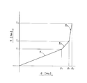
- the torsional characteristics are set in three stages by compressing the coil springs in the order of the large coil spring 20, the first small coil spring 22, and the second small coil spring 23.
- the stiffness ratio K2 / K1 between the first-stage torsional rigidity K1 and the second-stage torsional rigidity K1 is set to 1.5 or more and 4.0 or less.
- the rigidity ratio K3 / K2 between the second stage torsional rigidity K2 and the third stage torsional rigidity K3 is set to be larger than 4.0 is shown.
- the rigidity ratio K3 / K2 may be set to 1.5 or more and 4.0 or less.
- the first stage torsional rigidity K1 is defined by the absolute value of the first torque T1 with respect to the absolute value of the first angle ⁇ 1.
- the second stage torsional stiffness K2 is defined by the absolute value of the difference between the second torque T2 and the first torque T1 with respect to the absolute value of the difference between the second angle ⁇ 2 and the first angle ⁇ 1.
- the third stage torsional stiffness K3 is defined by the absolute value of the difference between the third torque T3 and the second torque T2 with respect to the absolute value of the difference between the third angle ⁇ 3 and the second angle ⁇ 2.
- the torsional characteristics can be set in multiple stages.
- a plurality of large coil springs 20 are arranged side by side in the circumferential direction on the outer side in the radial direction, and each of the plurality of small coil springs 21 moves on the inner peripheral portion of the large coil spring 20. Arranged as possible. That is, in the present lockup device 6, the plurality of large coil springs 20 and the plurality of small coil springs 21 are arranged on the outer peripheral side having a small axial thickness in the torque converter. Even if it is provided, the overall size of the apparatus can be reduced as compared with the prior art.
- the torsional characteristics can be set in multiple stages by setting the free lengths of the small coil springs 21 adjacent in the circumferential direction to different lengths. Specifically, in this case, as the torsion angle ⁇ increases, the torsion characteristics can be set in multiple stages by compressing the small coil springs 21 in order from the small coil spring 21 having the longer free length. Thus, in the present lockup device 6, the torsional characteristics can be set in multiple stages without adding a coil spring. That is, the overall size of the device can be reduced while setting the torsional characteristics of the lockup device 6 in multiple stages.
- the torsional characteristics can be set in multiple stages without adding a space for the coil spring. That is, the overall size of the device can be reduced while setting the torsional characteristics of the lockup device 6 in multiple stages.
- FIG. 4 shows a lockup device according to the second embodiment.
- the configuration of the lockup device of the second embodiment is the same as that of the first embodiment except for the configuration of the small coil spring 21.
- description is abbreviate
- symbol is attached
- the torsion spring 12 is disposed in the window portion 32 of the drive plate 9.
- the torsion spring 12 includes, for example, a large coil spring 20, a small coil spring 21, and a spring seat 29.
- the large coil spring 20 functions as an elastic member between the drive plate 9 and the driven plate 10.
- the large coil spring 20 is disposed radially outward. Specifically, the plurality of large coil springs 20 are arranged in the circumferential direction on the outer side in the radial direction. A plurality of large coil springs 20, for example, eight large coil springs 20, are arranged at equal intervals in the circumferential direction. The free lengths of the large coil springs 20 arranged to face each other in the radial direction are the same. The large coil spring 20 is compressed in the rotational direction by the relative rotation of the drive plate 9 and the driven plate 10.
- the small coil spring 21 functions as an elastic member between the drive plate 9 and the driven plate 10.
- the small coil springs 21 are movably disposed on the inner peripheral portions of the plurality of (for example, eight) large coil springs 20.
- the small coil spring 21 is set to have a shorter free length than the large coil spring 20.
- the small coil spring 21 is movably disposed between the first spring contact portion 40 and the second spring contact portion 41 of the drive plate 9 and the spring support claw 51 of the driven plate 10. . Until the small coil spring 21 is compressed between the first spring contact portion 40 and the second spring contact portion 41 of the drive plate 9 and the spring support claw 51 of the driven plate 10, the small coil spring 21 is not compressed. Is freely movable on the inner periphery of the large coil spring 20. When the small coil spring 21 is compressed between the first spring contact portion 40 and the second spring contact portion 41 of the drive plate 9 and the spring support claw 51 of the driven plate 10, the small coil spring 21 is compressed. Is immovable on the inner periphery of the large coil spring 20.
- each of the plurality of (for example, eight) small coil springs 21 includes a first small coil spring 22, a second small coil spring 23, and a third small coil spring 24.
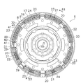
- the first small coil spring 22, the second small coil spring 23, and the third small coil spring 24 are disposed on the inner peripheral portion of the large coil spring 20 at intervals in the circumferential direction. That is, the first to third small coil springs 22, 23, 24 are arranged in the order of the first small coil spring 22, the second small coil spring 23, and the third small coil spring 24 in the circumferential direction. Arranged separately on the inner periphery.
- the free length of the first small coil spring 22 is longer than the free length of the second small coil spring 23 and the free length of the third small coil spring 24.
- the free length of the second small coil spring 23 is longer than the free length of the third small coil spring 24.
- the eight small coil springs 21 are arranged in the circumferential direction with a first small coil spring 22, a second small coil spring 23, a third small coil spring 24, a second small coil spring 23, and a first small coil spring 23.
- the small coil spring 22, the second small coil spring 23, the third small coil spring 24, and the second small coil spring 23 are arranged in this order.
- the free lengths of the two small coil springs 21 arranged opposite to each other in the radial direction are the same.
- the free lengths of the two first small coil springs 22 arranged to face each other in the radial direction are the same.
- the free lengths of the two second small coil springs 23 arranged to face each other in the radial direction are the same.
- the free lengths of the two third small coil springs 24 arranged to face each other in the radial direction are the same.
- N is a natural number.
- Spring seats 29 are disposed at both ends of the large coil spring 20. Specifically, the spring seat 29 is disposed between the end portion of the large coil spring 20 and the drive plate 9 (the first spring contact portion 40 and the second spring contact portion 41). The spring seat 29 is disposed between the end of the large coil spring 20 and the driven plate 10 (spring support claw 51).
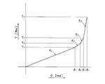
- the torsional characteristics are obtained by compressing the coil springs in the order of the large coil spring 20, the first small coil spring 22, the second small coil spring 23, and the third small coil spring 24. Is set to 4 stages.
- the stiffness ratio K2 / K1 between the first-stage torsional rigidity K1 and the second-stage torsional rigidity K1 is set to 1.5 or more and 4.0 or less.
- the rigidity ratio K3 / K2 between the second stage torsional rigidity K2 and the third stage torsional rigidity K3 is also set to 1.5 or more and 4.0 or less.
- the rigidity ratio K4 / K3 between the third stage torsional rigidity K3 and the fourth stage torsional rigidity K4 is set to be larger than 4.0 is shown.
- the rigidity ratio K4 / K3 may be set to 1.5 or more and 4.0 or less.
- the first stage torsional rigidity K1 is defined by the absolute value of the first torque T1 with respect to the absolute value of the first angle ⁇ 1.
- the second stage torsional stiffness K2 is defined by the absolute value of the difference between the second torque T2 and the first torque T1 with respect to the absolute value of the difference between the second angle ⁇ 2 and the first angle ⁇ 1.
- the third stage torsional stiffness K3 is defined by the absolute value of the difference between the third torque T3 and the first torque T2 with respect to the absolute value of the difference between the third angle ⁇ 3 and the second angle ⁇ 2.
- the fourth stage torsional rigidity K4 is defined by the absolute value of the difference between the fourth torque T4 and the third torque T3 with respect to the absolute value of the difference between the fourth angle ⁇ 4 and the third angle ⁇ 3.
- the torsional characteristics can be set in multiple stages without adding a coil spring. That is, the overall size of the device can be reduced while setting the torsional characteristics of the lockup device 6 in multiple stages.
- FIG. 6 and 7 show a lockup device according to a third embodiment.
- the configuration of the lock-up device of the third embodiment is the same as that of the first embodiment except for the configurations of the drive plate 9, the driven plate 10, the small coil spring 21, and the parallel coil spring 27.
- description is abbreviate
- symbol is attached
- the drive plate 9 is fixed to the piston 8, holds the torsion spring 12, and functions as an input member that inputs torque to the torsion spring 12.
- the drive plate 9 is an annular plate member and is disposed on the axial transmission side (turbine 5 side) of the outer peripheral portion of the piston 8.
- the drive plate 9 is carbonitrided on the entire surface.
- the drive plate 9 includes an annular portion 25 on the inner peripheral side, a spring support portion 26 on the outer peripheral side, a first spring contact portion 40 and a second spring contact portion 41.
- the annular portion 25 is fixed to the outer peripheral portion of the piston 8 by a plurality of rivets 28 arranged in the circumferential direction.
- the spring support portion 26 extends from the annular portion 25 to the outer peripheral side, and is disposed on the axial transmission side of the friction coupling portion 15 of the piston 8. That is, the spring support portion 26 is supported on the surface of the friction coupling portion 15 of the piston 8 on the turbine 5 side, and is supported on the inner peripheral surface of the outer peripheral side cylindrical portion 17. Further, as shown in FIG. 7, the spring support portion 26 is provided with a first window portion 32 and a second window portion 33. The large coil spring 20 is disposed in the first window portion 32. A parallel coil spring 27 to be described later is disposed in the second window portion 33.
- the driven plate 10 is a member that outputs torque from the torsion spring 12.
- the driven plate 10 is an annular and disk-shaped member.
- the driven plate 10 is disposed between the axial directions of the turbine 5 and the piston 8.
- the inner peripheral portion of the driven plate 10 is fixed to the flange 61.
- a plurality of spring support claws 51 are formed on the outer peripheral edge of the driven plate 10.
- the spring support claws 51 are in contact with both ends of the large coil spring 20.
- the driven plate 10 is formed with a notch hole (not shown) for arranging the large coil spring 20.
- the driven plate 10 is formed with a notch 35 for arranging the parallel coil spring 27.
- the torsion spring 12 includes, for example, a large coil spring 20, a small coil spring 21, a parallel coil spring 27, a spring seat 29, and the like.
- the large coil spring 20 functions as an elastic member between the drive plate 9 and the driven plate 10.
- the large coil spring 20 is disposed radially outward. Specifically, the plurality of large coil springs 20 are arranged in the circumferential direction on the outer side in the radial direction. A plurality of large coil springs 20, for example, eight large coil springs 20, are arranged at equal intervals in the circumferential direction. The free lengths of the large coil springs 20 arranged to face each other in the radial direction are the same. The large coil spring 20 is compressed in the rotational direction by the relative rotation of the drive plate 9 and the driven plate 10.
- the small coil spring 21 functions as an elastic member between the drive plate 9 and the driven plate 10.
- the small coil springs 21 are movably disposed on the inner peripheral portions of the plurality of (for example, eight) large coil springs 20.
- the small coil spring 21 is set to have a shorter free length than the large coil spring 20.
- the free lengths of the eight small coil springs 21 are the same.
- the small coil spring 21 is movably disposed between the first spring contact portion 40 and the second spring contact portion 41 of the drive plate 9 and the spring support claw 51 of the driven plate 10. . Until the small coil spring 21 is compressed between the first spring contact portion 40 and the second spring contact portion 41 of the drive plate 9 and the spring support claw 51 of the driven plate 10, the small coil spring 21 is not compressed. Is freely movable on the inner periphery of the large coil spring 20. When the small coil spring 21 is compressed between the first spring contact portion 40 and the second spring contact portion 41 of the drive plate 9 and the spring support claw 51 of the driven plate 10, the small coil spring 21 is compressed. Is immovable on the inner periphery of the large coil spring 20.
- the parallel coil spring 27 functions as an elastic member between the drive plate 9 and the driven plate 10.
- the plurality of (for example, six) parallel coil springs 27 are arranged at intervals in the circumferential direction on the inner side in the radial direction from the plurality of (for example, eight) large coil springs 20.
- the free lengths of the parallel coil springs 27 arranged to face each other in the radial direction are the same.
- the parallel coil spring 27 is disposed in the second window 33 of the drive plate 9. Both end portions of the parallel coil spring 27 are held by the second window portion 33.
- the parallel coil spring 27 is disposed in the cutout hole 35 of the driven plate 10.
- a predetermined space S (gap) is formed between the end of the parallel coil spring 27 and the wall surface of the cutout hole 35 in the circumferential direction. In other words, the free length of the parallel coil spring 27 is set shorter than the circumferential length of the cutout hole 35.
- the parallel coil spring 27 operates in parallel with the large coil spring 20. Specifically, when the twist angle becomes a predetermined angle due to the relative rotation between the drive plate 9 and the driven plate 10, the end of the parallel coil spring 27 comes into contact with the driven plate 10. Thereby, the large coil spring 20 and the parallel coil spring 27 are compressed in parallel.
- the rigidity ratio K ((N + 1) torsional rigidity K (n) and (N + 1) th torsional rigidity K (n + 1).
- the rigidity of the large coil spring 20, the rigidity of the small coil spring 21, and the parallel coil spring 27 are set so that (n + 1) / K (n) is 1.5 or more and 4.0 or less.
- N is a natural number.
- Spring seats 29 are disposed at both ends of the large coil spring 20. Specifically, the spring seat 29 is disposed between the end portion of the large coil spring 20 and the drive plate 9 (the first spring contact portion 40 and the second spring contact portion 41). The spring seat 29 is disposed between the end of the large coil spring 20 and the driven plate 10 (spring support claw 51).
- the spring seats 29 are not arranged at both ends of the parallel coil spring 27 , but the spring seats 29 may be arranged at both ends of the parallel coil spring 27.
- the torsional characteristics are set in three stages by compressing each coil spring in the order of the large coil spring 20, the small coil spring 21, and the parallel coil spring 27.
- the stiffness ratio K2 / K1 between the first-stage torsional rigidity K1 and the second-stage torsional rigidity K1 is set to 1.5 or more and 4.0 or less.
- the rigidity ratio K3 / K2 between the second stage torsional rigidity K2 and the third stage torsional rigidity K3 is set to be larger than 4.0.
- the rigidity ratio K3 / K2 may be set to 1.5 or more and 4.0 or less.
- the first stage torsional rigidity K1 is defined by the absolute value of the first torque T1 with respect to the absolute value of the first angle ⁇ 1.
- the second stage torsional stiffness K2 is defined by the absolute value of the difference between the second torque T2 and the first torque T1 with respect to the absolute value of the difference between the second angle ⁇ 2 and the first angle ⁇ 1.
- the third stage torsional stiffness K3 is defined by the absolute value of the difference between the third torque T3 and the first torque T2 with respect to the absolute value of the difference between the third angle ⁇ 3 and the second angle ⁇ 2.
- each space S (gap) is constant has been described.
- (D) In the third embodiment, an example in which the free lengths of the plurality of small coil springs 21 are the same has been described. However, at least one of the free lengths of the plurality of small coil springs 21 is different. You may set as follows. Thereby, torsional characteristics of three or more steps can be formed. For example, when the same small coil spring 21 as in the first embodiment is used, the four-stage torsional characteristics shown in FIG. 5 can be formed. For example, when the small coil spring 21 similar to that of the second embodiment is used, a five-stage torsion characteristic can be formed.
Landscapes
- Engineering & Computer Science (AREA)
- General Engineering & Computer Science (AREA)
- Mechanical Engineering (AREA)
- Physics & Mathematics (AREA)
- Acoustics & Sound (AREA)
- Aviation & Aerospace Engineering (AREA)
- Mechanical Operated Clutches (AREA)
- Springs (AREA)
Abstract
Description
[トルクコンバータの構成]
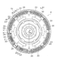
図1は、本発明の一実施形態としてのトルクコンバータ1の縦断面概略図を示している。 図1の左側にエンジン(図示せず)が配置され、図1の右側にトランスミッション(図示せず)が配置されている。図1のR1方向は、正回転方向を示す。また、図1に記載のO-Oがトルクコンバータ1の回転軸線であり、図2に記載の矢印R1がエンジンの回転方向、矢印R2がその反対側回転方向である。
ここでは、図1及び図2を用いて、ロックアップ装置6について説明する。ロックアップ装置6は、フロントカバー3からトルクを機械的にタービン5に伝達しつつ、入力された捩じり振動を吸収・減衰するための装置である。すなわち、ロックアップ装置6は、クラッチ機能とダンパー機能とを有している。ロックアップ装置6は、図1に示すように、フロントカバー3とタービン5との間の空間に、配置されている。ロックアップ装置6は、主に、ピストン8と、ドライブプレート9と、ドリブンプレート10と、複数のトーションスプリング12とから、構成されている。これら部材は、全体でダンパー機構13を構成している。ダンパー機構13において、ドライブプレート9は、入力回転部材として機能し、ドリブンプレート10は出力回転部材として機能し、トーションスプリング12は、両部材間の弾性部材として機能する。なお、ピストン8及びドライブプレート9が、入力回転部材として機能すると考えてもよい。
図2に示すように、トーションスプリング12は、大コイルスプリング20と、小コイルスプリング21と、スプリングシート29とを、有している。
ここでは、トルクコンバータ1の動作について説明する。図示しない油圧作動機構によってフロントカバー3とピストン8の内周部に作動油が供給されると、フロントカバー3とピストン8との間の空間を作動油が外周側に流れていく。作動油は、フロントカバー3と摩擦フェーシング16との間を通ってさらに外周側に流れ、トルクコンバータ1の本体内に流れ込む。この状態では、ピストン機構全体が、軸方向トランスミッション側に移動しており、摩擦連結部15におけるクラッチ連結は、解除されている。
ここでは、ロックアップ装置6の動作について、説明する。ドライブプレート9とドリブンプレート10とが相対回転を開始すると(ドライブプレート9がR1方向に回転すると)、まず、8個の大トーションスプリングが、ドライブプレート9(第1ばね当接部40及び第2ばね当接部41)とドリブンプレート10(ばね支持爪51)との間で、圧縮される。これにより、図3に示すように、1段目の捩り剛性K1が形成される。次に、捩り角度が所定の第1角度θ1以上になると、8個の大コイルスプリング20及び4個の第1小コイルスプリング22が、圧縮される。これにより、2段目の捩り剛性K2が形成される。続いて、捩り角度が所定の第2角度θ2以上になると、8個の大コイルスプリング20、4個の第1小コイルスプリング22、及び4個の第2小コイルスプリング23が、が、圧縮される。これにより、3段目の捩り剛性K3が形成される。なお、ドライブプレート9が、R1方向とは反対の方向に回転した場合も、同様の捩り特性が形成される。
(A1)本ロックアップ装置6では、ドライブプレート9とドリブンプレート10とが相対回転し、例えば、ドライブプレート9とドリブンプレート10との間に捩り角度が生じると、複数の大コイルスプリング20が圧縮される。これにより、捩り特性において、1段目の捩り剛性K1が形成される。次に、捩り角度が所定の第1角度θ1以上になると、複数の大コイルスプリング20及び複数の小コイルスプリング21のいずれか1つが、圧縮される。これにより、捩り特性において、2段目の捩り剛性K2が形成される。続いて、捩り角度が所定の第2角度θ2以上になると、複数の大コイルスプリング20及び複数の(全ての)小コイルスプリング21が、圧縮される。これにより、捩り特性において、3段目の捩り剛性K3が形成される。このように、本ロックアップ装置6では、捩り特性を多段に設定することができる。
図4に、第2実施形態によるロックアップ装置を示す。第2実施形態のロックアップ装置の構成は、小コイルスプリング21の構成を除いて、第1実施形態と同様である。このため、ここでは、第1実施形態と同様の構成については、説明を省略する。また、図4では、第1実施形態と同様の構成については、同じ符号を付している。なお、第2実施形態のトルクコンバータ本体についても、第1実施形態と同様の構成であるため、ここでは、トルクコンバータ本体についても、説明を省略する。
図4に示すように、トーションスプリング12は、ドライブプレート9の窓部32に、配置されている。トーションスプリング12は、例えば大コイルスプリング20、小コイルスプリング21、及びスプリングシート29等から、構成される。
ここでは、ロックアップ装置6の動作について、説明する。ドライブプレート9とドリブンプレート10とが相対回転を開始すると(ドライブプレート9がR1方向に回転すると)、まず、8個の大トーションスプリングが、ドライブプレート9(第1ばね当接部40及び第2ばね当接部41)とドリブンプレート10(ばね支持爪51)との間で、圧縮される。これにより、図5に示すように、1段目の捩り剛性K1が形成される。次に、捩り角度が所定の第1角度θ1以上になると、8個の大コイルスプリング20及び2個の第1小コイルスプリング22が、圧縮される。これにより、2段目の捩り剛性K2が形成される。続いて、捩り角度が所定の第2角度θ2以上になると、8個の大コイルスプリング20、2個の第1小コイルスプリング22、及び4個の第2小コイルスプリング23が、圧縮される。これにより、3段目の捩り剛性K3が形成される。続いて、捩り角度が所定の第3角度θ3以上になると、8個の大コイルスプリング20、2個の第1小コイルスプリング22、4個の第2小コイルスプリング23、及び2個の第3小コイルスプリング24が、圧縮される。これにより、4段目の捩り剛性K4が形成される。なお、ドライブプレート9が、R1方向とは反対の方向に回転した場合も、同様の捩り特性が形成される。
(B1)本ロックアップ装置6では、捩り角度が所定の第1角度θ1以上になると、複数の大コイルスプリング20及び自由長が1番長い小コイルスプリング21(第1小コイルスプリング22)が、圧縮される。これにより、捩り特性において、2段目の捩り剛性K2が形成される。次に、捩り角度が所定の第2角度θ2以上になると、複数の大コイルスプリング20、第1小コイルスプリング22、及び自由長が2番目に長い小コイルスプリング21(第2小コイルスプリング23)が、圧縮される。これにより、捩り特性において、3段目の捩り剛性K3が形成される。続いて、捩り角度が所定の第3角度θ3以上になると、複数の大コイルスプリング20及び複数の(全ての)小コイルスプリング21(第1から第3小コイルスプリング22,23,24)が、圧縮される。これにより、捩り特性において、4段目の捩り剛性K4が形成される。
図6及び図7に、第3実施形態によるロックアップ装置を示す。第3実施形態のロックアップ装置の構成は、ドライブプレート9、ドリブンプレート10、小コイルスプリング21、及び並列コイルスプリング27の構成を除いて、第1実施形態と同様である。このため、ここでは、第1実施形態と同様の構成については、説明を省略する。また、図6及び図7では、第1実施形態と同様の構成については、同じ符号を付している。なお、第3実施形態のトルクコンバータ本体についても、第1実施形態と同様の構成であるため、ここでは、トルクコンバータ本体についても、説明を省略する。
図6及び図7に示すように、ドライブプレート9は、ピストン8に固定され、トーションスプリング12を保持するとともに、トーションスプリング12にトルクを入力する入力部材として、機能する。ドライブプレート9は、環状プレート部材であり、ピストン8の外周部の軸方向トランスミッション側(タービン5側)に配置されている。ドライブプレート9は、全面に浸炭窒化処理が施されている。ドライブプレート9は、内周側の環状部25と、外周側のばね支持部26と、第1ばね当接部40及び第2ばね当接部41とから、構成されている。環状部25は、円周方向に並んだ複数のリベット28によって、ピストン8の外周部に固定されている。
ここでは、ロックアップ装置6の動作について、説明する。ドライブプレート9とドリブンプレート10とが相対回転を開始すると(ドライブプレート9がR1方向に回転すると)、まず、8個の大トーションスプリングが、ドライブプレート9(第1ばね当接部40及び第2ばね当接部41)とドリブンプレート10(ばね支持爪51)との間で、圧縮される。これにより、図3に示すように、1段目の捩り剛性K1が形成される。次に、捩り角度が所定の第1角度θ1以上になると、8個の大コイルスプリング20及び8個の小コイルスプリング21が、圧縮される。これにより、2段目の捩り剛性K2が形成される。続いて、捩り角度が所定の第2角度θ2以上になると、8個の大コイルスプリング20、8個の小コイルスプリング21、及び6個の並列コイルスプリング27が、が、圧縮される。これにより、3段目の捩り剛性K3が形成される。なお、ドライブプレート9が、R1方向とは反対の方向に回転した場合も、同様の捩り特性が形成される。
(C1)本ロックアップ装置6では、大コイルスプリング20の内周側に、複数の並列コイルスプリング27を、さらに備えているので、捩り特性の段数をさらに増やすことができる。このように、捩り特性の段数を増やすことによって、最大トルクに至るまでの捩り特性のカーブを滑らかに形成することができる。
(a)前記第1から第3実施形態では、各大コイルスプリング20の剛性は、同じである場合を想定しているが、この剛性はどのように設定してもよい。また、各小コイルスプリング21(第1から第3小コイルスプリング22,23,24)の剛性は、同じである場合を想定しているが、この剛性はどのように設定してもよい。さらに、各並列コイルスプリング27の剛性は、同じである場合を想定しているが、この剛性はどのように設定してもよい。この場合であっても、前記第1から第3実施形態と同様の効果を得ることができる。
3 フロントカバー
6 ロックアップ装置
9 ドライブプレート(入力回転部材)
10 ドリブンプレート(出力回転部材)
12 トーションスプリング
20 大コイルスプリング
21 小コイルスプリング
22 第1小コイルスプリング
23 第2小コイルスプリング
24 第3小コイルスプリング
27 並列コイルスプリング
S 空間
Claims (9)
- トルクを伝達するとともに捩り振動を吸収・減衰するためのトルクコンバータのロックアップ装置であって、
入力回転部材と、
前記入力回転部材に対して回転可能に配置される出力回転部材と、
径方向外方において円周方向に並べて配置され、前記入力回転部材と前記出力回転部材との相対回転によって回転方向に各別に圧縮される複数の大コイルスプリングと、
前記大コイルスプリングより自由長が短く設定され、前記大コイルスプリングの内周部において移動可能に各別に配置される複数の小コイルスプリングと、
を備え、
前記入力回転部材と前記出力回転部材との相対回転によって、複数の前記大コイルスプリング、複数の前記小コイルスプリングの少なくともいずれか1つの順に、各コイルスプリングは圧縮される、
トルクコンバータのロックアップ装置。 - 径方向に対向して配置される前記大コイルスプリングの自由長は、同じであり、
径方向に対向して配置される前記小コイルスプリングの自由長は、同じである、
請求項1に記載のトルクコンバータのロックアップ装置。 - 円周方向に隣り合う前記小コイルスプリングの自由長は、異なっている、
請求項1又は2に記載のトルクコンバータのロックアップ装置。 - 複数の前記小コイルスプリングには、第1小コイルスプリング及び第2小コイルスプリングが、含まれており、
前記第1小コイルスプリング及び第2小コイルスプリングは、円周方向に隣り合うように、前記大コイルスプリングの内周部に配置され、
前記第1小コイルスプリングの自由長と、前記第2小コイルスプリングの自由長とは、異なっている、
請求項3に記載のトルクコンバータのロックアップ装置。 - 複数の前記小コイルスプリングには、第3小コイルスプリングが、さらに含まれており、
前記第1から第3小コイルスプリングは、円周方向において、前記第1小コイルスプリング、前記第2小コイルスプリング、前記第3小コイルスプリングの順に、前記大コイルスプリングの内周部に各別に配置され、
前記第1小コイルスプリングの自由長は、前記第2小コイルスプリング及び前記第3小コイルスプリングのいずれか一方の自由長より長く、
前記第2小コイルスプリング及び前記第3小コイルスプリングのいずれか一方の自由長は、前記第2小コイルスプリング及び前記第3小コイルスプリングのいずれか他方の自由長より、長い、
請求項4に記載のトルクコンバータのロックアップ装置。 - 前記入力回転部材と前記出力回転部材との相対回転に対応する捩り角度に応じて、前記大コイルスプリング及び前記小コイルスプリングの少なくともいずれか一方を圧縮することによって形成される、前記捩り角度と前記トルクとの関係を示す複数段の捩り特性の少なくとも1つの屈曲点において、第N捩り剛性と第N+1捩り剛性との剛性比が、1.5以上4.0以下に設定される(Nは自然数)、
請求項1から5のいずれかに記載のトルクコンバータのロックアップ装置。 - 前記大コイルスプリングより径方向内方において円周方向に並べて配置され、前記大コイルスプリングと並列に各別に作動する複数の並列コイルスプリング、
をさらに備え、
前記入力回転部材と前記出力回転部材との相対回転によって、複数の前記大コイルスプリング、複数の前記小コイルスプリングの少なくともいずれか1つ、複数の並列コイルスプリングの少なくとも1つの順に、各コイルスプリングが圧縮される、
請求項1から5のいずれかに記載のトルクコンバータのロックアップ装置。 - 前記並列コイルスプリングと、前記入力回転部材及び前記出力回転部材のいずれか一方との間には、円周方向に空間が形成されており、
前記入力回転部材と前記出力回転部材との相対回転に対応する捩り角度が所定の角度になった場合に、複数の並列コイルスプリングの少なくとも1つが、圧縮される、
請求項7に記載のトルクコンバータのロックアップ装置。 - 前記入力回転部材と前記出力回転部材との相対回転に対応する捩り角度に応じて、前記大コイルスプリング、前記小コイルスプリング、及び前記並列コイルスプリングの少なくともいずれか1つを圧縮することによって形成される、前記捩り角度と前記トルクとの関係を示す複数段の捩り特性の少なくとも1つの屈曲点において、第N捩り剛性と第N+1捩り剛性との剛性比が、1.5以上4.0以下に設定される(Nは自然数)、
請求項7又は8に記載のトルクコンバータのロックアップ装置。
Priority Applications (5)
| Application Number | Priority Date | Filing Date | Title |
|---|---|---|---|
| KR1020157032164A KR102196854B1 (ko) | 2013-05-16 | 2014-03-20 | 토크 컨버터의 록업 장치 |
| US14/888,349 US10036459B2 (en) | 2013-05-16 | 2014-03-20 | Lock-up device for torque converter |
| CN202010277757.0A CN111396526B (zh) | 2013-05-16 | 2014-03-20 | 液力变矩器的锁定装置 |
| CN201480025628.5A CN105190103A (zh) | 2013-05-16 | 2014-03-20 | 液力变矩器的锁定装置 |
| DE112014002406.6T DE112014002406T5 (de) | 2013-05-16 | 2014-03-20 | Überbrückungsvorrichtung für einen Drehmomentwandler |
Applications Claiming Priority (2)
| Application Number | Priority Date | Filing Date | Title |
|---|---|---|---|
| JP2013-103681 | 2013-05-16 | ||
| JP2013103681A JP5805704B2 (ja) | 2013-05-16 | 2013-05-16 | トルクコンバータのロックアップ装置 |
Publications (1)
| Publication Number | Publication Date |
|---|---|
| WO2014185147A1 true WO2014185147A1 (ja) | 2014-11-20 |
Family
ID=51898132
Family Applications (1)
| Application Number | Title | Priority Date | Filing Date |
|---|---|---|---|
| PCT/JP2014/057721 Ceased WO2014185147A1 (ja) | 2013-05-16 | 2014-03-20 | トルクコンバータのロックアップ装置 |
Country Status (6)
| Country | Link |
|---|---|
| US (1) | US10036459B2 (ja) |
| JP (1) | JP5805704B2 (ja) |
| KR (1) | KR102196854B1 (ja) |
| CN (2) | CN111396526B (ja) |
| DE (1) | DE112014002406T5 (ja) |
| WO (1) | WO2014185147A1 (ja) |
Cited By (1)
| Publication number | Priority date | Publication date | Assignee | Title |
|---|---|---|---|---|
| EP3271609A4 (en) * | 2015-03-20 | 2019-03-20 | Litens Automotive Partnership | ISOLATOR WITH FIRST AND SECOND SPRING INSULATORS IN ROW |
Families Citing this family (6)
| Publication number | Priority date | Publication date | Assignee | Title |
|---|---|---|---|---|
| JP6174332B2 (ja) * | 2013-02-18 | 2017-08-02 | 株式会社エフ・シー・シー | トルクダンパ装置 |
| JP6745114B2 (ja) * | 2016-02-05 | 2020-08-26 | 株式会社エクセディ | ダンパ装置及びトルクコンバータのロックアップ装置 |
| JP6998648B2 (ja) * | 2016-03-25 | 2022-01-18 | 株式会社エクセディ | スプリング組立体及びそれを備えたトルクコンバータのロックアップ装置 |
| DE102017106230A1 (de) * | 2017-03-23 | 2018-09-27 | Schaeffler Technologies AG & Co. KG | Drehschwingungsdämpfer |
| US10352423B2 (en) * | 2017-05-16 | 2019-07-16 | Valeo Embrayages | Hydrokinetic torque coupling device with centered friction disc |
| CN113324007B (zh) * | 2021-06-29 | 2022-05-13 | 吉林大学 | 一种具有多级减振功能的液力变矩器装置 |
Citations (5)
| Publication number | Priority date | Publication date | Assignee | Title |
|---|---|---|---|---|
| JP2009243599A (ja) * | 2008-03-31 | 2009-10-22 | Aisin Aw Co Ltd | ダンパ装置 |
| JP2010031951A (ja) * | 2008-07-28 | 2010-02-12 | Exedy Corp | ロックアップ装置および流体式動力伝達装置 |
| JP2011179515A (ja) * | 2010-02-26 | 2011-09-15 | Exedy Corp | トルクコンバータ用のロックアップ装置 |
| JP2011252584A (ja) * | 2010-06-04 | 2011-12-15 | Exedy Corp | トルクコンバータ用のロックアップ装置 |
| JP2012219999A (ja) * | 2011-04-14 | 2012-11-12 | Exedy Corp | トルクコンバータ用のロックアップ装置 |
Family Cites Families (15)
| Publication number | Priority date | Publication date | Assignee | Title |
|---|---|---|---|---|
| JPH0266360A (ja) * | 1988-07-07 | 1990-03-06 | Atsugi Unisia Corp | 自動変速機の動力伝達装置 |
| CN1062814C (zh) | 1993-09-17 | 2001-03-07 | 卢克驱动系统有限公司 | 用于带变扭器的机动车的转矩传递系统 |
| DE19909044B4 (de) | 1998-03-07 | 2018-06-21 | Schaeffler Technologies AG & Co. KG | Drehschwingungsdämpfer |
| DE10024191B4 (de) * | 1999-05-21 | 2012-06-28 | Schaeffler Technologies Gmbh & Co. Kg | Drehmomentübertragungseinrichtung |
| DE10342035B4 (de) * | 2002-09-25 | 2006-07-20 | Exedy Corp., Neyagawa | Kolbenverbindungsmechanismus, Überbrückungsvorrichtung für eine fluidische Drehmomentübertragungsvorrichtung, elastischer Verbindungsmechanismus und Verfahren zur Federmontage für einen elastischen Verbindungsmechanismus |
| JP4788545B2 (ja) * | 2006-09-25 | 2011-10-05 | マツダ株式会社 | トルクコンバータ |
| JP4385045B2 (ja) * | 2006-10-02 | 2009-12-16 | 株式会社エクセディ | ダンパー機構 |
| JP2009250288A (ja) * | 2008-04-02 | 2009-10-29 | Exedy Corp | ロックアップ装置 |
| JP4773553B2 (ja) * | 2009-08-26 | 2011-09-14 | 株式会社エクセディ | トルクコンバータ用ロックアップ装置 |
| JP2011122622A (ja) * | 2009-12-09 | 2011-06-23 | Exedy Corp | トルクコンバータ用ロックアップ装置 |
| KR101660478B1 (ko) | 2010-02-26 | 2016-09-27 | 가부시키가이샤 에쿠세디 | 토크 컨버터의 록업 장치 |
| JP4949503B2 (ja) * | 2010-06-04 | 2012-06-13 | 株式会社エクセディ | トルクコンバータ用のロックアップ装置 |
| JP4930867B1 (ja) * | 2010-11-11 | 2012-05-16 | 株式会社エクセディ | トルクコンバータ用ロックアップ装置 |
| WO2012144009A1 (ja) * | 2011-04-18 | 2012-10-26 | トヨタ自動車株式会社 | 車両用トルクコンバータ |
| CN102748506B (zh) * | 2012-06-21 | 2013-12-18 | 中煤张家口煤矿机械有限责任公司 | 电液先导控制开关阀组 |
-
2013
- 2013-05-16 JP JP2013103681A patent/JP5805704B2/ja active Active
-
2014
- 2014-03-20 CN CN202010277757.0A patent/CN111396526B/zh active Active
- 2014-03-20 KR KR1020157032164A patent/KR102196854B1/ko active Active
- 2014-03-20 US US14/888,349 patent/US10036459B2/en active Active
- 2014-03-20 DE DE112014002406.6T patent/DE112014002406T5/de not_active Ceased
- 2014-03-20 CN CN201480025628.5A patent/CN105190103A/zh active Pending
- 2014-03-20 WO PCT/JP2014/057721 patent/WO2014185147A1/ja not_active Ceased
Patent Citations (5)
| Publication number | Priority date | Publication date | Assignee | Title |
|---|---|---|---|---|
| JP2009243599A (ja) * | 2008-03-31 | 2009-10-22 | Aisin Aw Co Ltd | ダンパ装置 |
| JP2010031951A (ja) * | 2008-07-28 | 2010-02-12 | Exedy Corp | ロックアップ装置および流体式動力伝達装置 |
| JP2011179515A (ja) * | 2010-02-26 | 2011-09-15 | Exedy Corp | トルクコンバータ用のロックアップ装置 |
| JP2011252584A (ja) * | 2010-06-04 | 2011-12-15 | Exedy Corp | トルクコンバータ用のロックアップ装置 |
| JP2012219999A (ja) * | 2011-04-14 | 2012-11-12 | Exedy Corp | トルクコンバータ用のロックアップ装置 |
Cited By (2)
| Publication number | Priority date | Publication date | Assignee | Title |
|---|---|---|---|---|
| EP3271609A4 (en) * | 2015-03-20 | 2019-03-20 | Litens Automotive Partnership | ISOLATOR WITH FIRST AND SECOND SPRING INSULATORS IN ROW |
| US10794448B2 (en) | 2015-03-20 | 2020-10-06 | Litens Automotive Partnership | Isolator that includes first and second isolation spring arrangement in series |
Also Published As
| Publication number | Publication date |
|---|---|
| CN105190103A (zh) | 2015-12-23 |
| JP5805704B2 (ja) | 2015-11-04 |
| KR102196854B1 (ko) | 2020-12-30 |
| JP2014224559A (ja) | 2014-12-04 |
| CN111396526B (zh) | 2023-06-27 |
| CN111396526A (zh) | 2020-07-10 |
| DE112014002406T5 (de) | 2016-07-07 |
| US20160061306A1 (en) | 2016-03-03 |
| KR20160010447A (ko) | 2016-01-27 |
| US10036459B2 (en) | 2018-07-31 |
Similar Documents
| Publication | Publication Date | Title |
|---|---|---|
| JP5805704B2 (ja) | トルクコンバータのロックアップ装置 | |
| JP5852701B2 (ja) | 流体式動力伝達装置 | |
| JP5952432B2 (ja) | ダンパ装置および発進装置 | |
| JP5315377B2 (ja) | トルクコンバータ用のロックアップ装置 | |
| JP4773553B2 (ja) | トルクコンバータ用ロックアップ装置 | |
| US9989136B2 (en) | Starting device | |
| JP6252458B2 (ja) | ダンパ装置 | |
| JP2011122640A (ja) | トルクコンバータ用ロックアップ装置 | |
| WO2014185148A1 (ja) | トルクコンバータのロックアップ装置 | |
| US10711862B2 (en) | Damper device | |
| CN105190102B (zh) | 液力变矩器用的锁定装置 | |
| US20100187066A1 (en) | Low friction arc spring damper | |
| JP2020148262A (ja) | トルク変動抑制装置、及びトルクコンバータ | |
| JP2017190844A (ja) | ダンパ装置 | |
| US8382598B2 (en) | Modularity spacer for a damper | |
| JP2020148264A (ja) | トルク変動抑制装置、及びトルクコンバータ | |
| JP7218221B2 (ja) | トルク変動抑制装置、及びトルクコンバータ | |
| CN107208768B (zh) | 液力变矩器的锁定装置 | |
| JP6348425B2 (ja) | トルクコンバータ用のロックアップ装置 | |
| KR101284342B1 (ko) | 토크 컨버터의 댐퍼 클러치 | |
| KR101338444B1 (ko) | 토크 컨버터의 댐퍼 클러치 | |
| JP2015031357A5 (ja) | ||
| JP2015031357A (ja) | トルクコンバータ用ロックアップ装置 |
Legal Events
| Date | Code | Title | Description |
|---|---|---|---|
| WWE | Wipo information: entry into national phase |
Ref document number: 201480025628.5 Country of ref document: CN |
|
| 121 | Ep: the epo has been informed by wipo that ep was designated in this application |
Ref document number: 14797075 Country of ref document: EP Kind code of ref document: A1 |
|
| WWE | Wipo information: entry into national phase |
Ref document number: 14888349 Country of ref document: US |
|
| ENP | Entry into the national phase |
Ref document number: 20157032164 Country of ref document: KR Kind code of ref document: A |
|
| WWE | Wipo information: entry into national phase |
Ref document number: 112014002406 Country of ref document: DE |
|
| 122 | Ep: pct application non-entry in european phase |
Ref document number: 14797075 Country of ref document: EP Kind code of ref document: A1 |