JP2017190844A - ダンパ装置 - Google Patents
ダンパ装置 Download PDFInfo
- Publication number
- JP2017190844A JP2017190844A JP2016081686A JP2016081686A JP2017190844A JP 2017190844 A JP2017190844 A JP 2017190844A JP 2016081686 A JP2016081686 A JP 2016081686A JP 2016081686 A JP2016081686 A JP 2016081686A JP 2017190844 A JP2017190844 A JP 2017190844A
- Authority
- JP
- Japan
- Prior art keywords
- plate
- retaining
- spring
- retaining plate
- divided
- Prior art date
- Legal status (The legal status is an assumption and is not a legal conclusion. Google has not performed a legal analysis and makes no representation as to the accuracy of the status listed.)
- Granted
Links
Images


Classifications
-
- F—MECHANICAL ENGINEERING; LIGHTING; HEATING; WEAPONS; BLASTING
- F16—ENGINEERING ELEMENTS AND UNITS; GENERAL MEASURES FOR PRODUCING AND MAINTAINING EFFECTIVE FUNCTIONING OF MACHINES OR INSTALLATIONS; THERMAL INSULATION IN GENERAL
- F16H—GEARING
- F16H41/00—Rotary fluid gearing of the hydrokinetic type
- F16H41/24—Details
-
- F—MECHANICAL ENGINEERING; LIGHTING; HEATING; WEAPONS; BLASTING
- F16—ENGINEERING ELEMENTS AND UNITS; GENERAL MEASURES FOR PRODUCING AND MAINTAINING EFFECTIVE FUNCTIONING OF MACHINES OR INSTALLATIONS; THERMAL INSULATION IN GENERAL
- F16F—SPRINGS; SHOCK-ABSORBERS; MEANS FOR DAMPING VIBRATION
- F16F15/00—Suppression of vibrations in systems; Means or arrangements for avoiding or reducing out-of-balance forces, e.g. due to motion
- F16F15/10—Suppression of vibrations in rotating systems by making use of members moving with the system
- F16F15/12—Suppression of vibrations in rotating systems by making use of members moving with the system using elastic members or friction-damping members, e.g. between a rotating shaft and a gyratory mass mounted thereon
- F16F15/121—Suppression of vibrations in rotating systems by making use of members moving with the system using elastic members or friction-damping members, e.g. between a rotating shaft and a gyratory mass mounted thereon using springs as elastic members, e.g. metallic springs
- F16F15/123—Wound springs
- F16F15/12353—Combinations of dampers, e.g. with multiple plates, multiple spring sets, i.e. complex configurations
- F16F15/1236—Combinations of dampers, e.g. with multiple plates, multiple spring sets, i.e. complex configurations resulting in a staged spring characteristic, e.g. with multiple intermediate plates
- F16F15/12366—Combinations of dampers, e.g. with multiple plates, multiple spring sets, i.e. complex configurations resulting in a staged spring characteristic, e.g. with multiple intermediate plates acting on multiple sets of springs
-
- F—MECHANICAL ENGINEERING; LIGHTING; HEATING; WEAPONS; BLASTING
- F16—ENGINEERING ELEMENTS AND UNITS; GENERAL MEASURES FOR PRODUCING AND MAINTAINING EFFECTIVE FUNCTIONING OF MACHINES OR INSTALLATIONS; THERMAL INSULATION IN GENERAL
- F16F—SPRINGS; SHOCK-ABSORBERS; MEANS FOR DAMPING VIBRATION
- F16F15/00—Suppression of vibrations in systems; Means or arrangements for avoiding or reducing out-of-balance forces, e.g. due to motion
- F16F15/10—Suppression of vibrations in rotating systems by making use of members moving with the system
- F16F15/12—Suppression of vibrations in rotating systems by making use of members moving with the system using elastic members or friction-damping members, e.g. between a rotating shaft and a gyratory mass mounted thereon
- F16F15/121—Suppression of vibrations in rotating systems by making use of members moving with the system using elastic members or friction-damping members, e.g. between a rotating shaft and a gyratory mass mounted thereon using springs as elastic members, e.g. metallic springs
- F16F15/123—Wound springs
- F16F15/1232—Wound springs characterised by the spring mounting
-
- F—MECHANICAL ENGINEERING; LIGHTING; HEATING; WEAPONS; BLASTING
- F16—ENGINEERING ELEMENTS AND UNITS; GENERAL MEASURES FOR PRODUCING AND MAINTAINING EFFECTIVE FUNCTIONING OF MACHINES OR INSTALLATIONS; THERMAL INSULATION IN GENERAL
- F16F—SPRINGS; SHOCK-ABSORBERS; MEANS FOR DAMPING VIBRATION
- F16F2228/00—Functional characteristics, e.g. variability, frequency-dependence
- F16F2228/06—Stiffness
- F16F2228/066—Variable stiffness
-
- F—MECHANICAL ENGINEERING; LIGHTING; HEATING; WEAPONS; BLASTING
- F16—ENGINEERING ELEMENTS AND UNITS; GENERAL MEASURES FOR PRODUCING AND MAINTAINING EFFECTIVE FUNCTIONING OF MACHINES OR INSTALLATIONS; THERMAL INSULATION IN GENERAL
- F16F—SPRINGS; SHOCK-ABSORBERS; MEANS FOR DAMPING VIBRATION
- F16F2230/00—Purpose; Design features
- F16F2230/0005—Attachment, e.g. to facilitate mounting onto confer adjustability
-
- F—MECHANICAL ENGINEERING; LIGHTING; HEATING; WEAPONS; BLASTING
- F16—ENGINEERING ELEMENTS AND UNITS; GENERAL MEASURES FOR PRODUCING AND MAINTAINING EFFECTIVE FUNCTIONING OF MACHINES OR INSTALLATIONS; THERMAL INSULATION IN GENERAL
- F16F—SPRINGS; SHOCK-ABSORBERS; MEANS FOR DAMPING VIBRATION
- F16F2232/00—Nature of movement
- F16F2232/02—Rotary
-
- F—MECHANICAL ENGINEERING; LIGHTING; HEATING; WEAPONS; BLASTING
- F16—ENGINEERING ELEMENTS AND UNITS; GENERAL MEASURES FOR PRODUCING AND MAINTAINING EFFECTIVE FUNCTIONING OF MACHINES OR INSTALLATIONS; THERMAL INSULATION IN GENERAL
- F16F—SPRINGS; SHOCK-ABSORBERS; MEANS FOR DAMPING VIBRATION
- F16F2236/00—Mode of stressing of basic spring or damper elements or devices incorporating such elements
- F16F2236/08—Torsion
-
- F—MECHANICAL ENGINEERING; LIGHTING; HEATING; WEAPONS; BLASTING
- F16—ENGINEERING ELEMENTS AND UNITS; GENERAL MEASURES FOR PRODUCING AND MAINTAINING EFFECTIVE FUNCTIONING OF MACHINES OR INSTALLATIONS; THERMAL INSULATION IN GENERAL
- F16H—GEARING
- F16H45/00—Combinations of fluid gearings for conveying rotary motion with couplings or clutches
- F16H45/02—Combinations of fluid gearings for conveying rotary motion with couplings or clutches with mechanical clutches for bridging a fluid gearing of the hydrokinetic type
- F16H2045/0221—Combinations of fluid gearings for conveying rotary motion with couplings or clutches with mechanical clutches for bridging a fluid gearing of the hydrokinetic type with damping means
- F16H2045/0226—Combinations of fluid gearings for conveying rotary motion with couplings or clutches with mechanical clutches for bridging a fluid gearing of the hydrokinetic type with damping means comprising two or more vibration dampers
-
- F—MECHANICAL ENGINEERING; LIGHTING; HEATING; WEAPONS; BLASTING
- F16—ENGINEERING ELEMENTS AND UNITS; GENERAL MEASURES FOR PRODUCING AND MAINTAINING EFFECTIVE FUNCTIONING OF MACHINES OR INSTALLATIONS; THERMAL INSULATION IN GENERAL
- F16H—GEARING
- F16H45/00—Combinations of fluid gearings for conveying rotary motion with couplings or clutches
- F16H45/02—Combinations of fluid gearings for conveying rotary motion with couplings or clutches with mechanical clutches for bridging a fluid gearing of the hydrokinetic type
Landscapes
- Engineering & Computer Science (AREA)
- General Engineering & Computer Science (AREA)
- Mechanical Engineering (AREA)
- Physics & Mathematics (AREA)
- Acoustics & Sound (AREA)
- Aviation & Aerospace Engineering (AREA)
- Mechanical Operated Clutches (AREA)
- Springs (AREA)
Abstract
【解決手段】ダンパ装置は、環状のリティニングプレート29と、複数のスプリング部材と、出力プレートと、を備えている。各スプリング部材は、リティニングプレート29に保持される。出力プレートは、スプリング部材を介してリティニングプレート29と弾性的に連結する。リティニングプレート29は、周方向において、複数の分割リティニングプレート291に分割されている。
【選択図】図4
Description
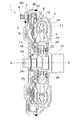
トルクコンバータ1は、図示しないフレキシブルプレートによってエンジン側の部材に連結され、エンジンのクランクシャフトからトランスミッションの入力シャフトにトルクを伝達するための装置である。トルクコンバータ1は、フロントカバー2と、インペラ3と、タービン4と、ステータ5と、ピストンプレート6と、ダンパ装置7と、を備えている。
フロントカバー2は、円板状の部材であり、内周端にはセンターボス2aが設けられ、外周部には、軸方向トランスミッション側に延びる外周側筒状部2bが形成されている。センターボス2aは、軸方向に延びる円筒形状の部材であり、クランクシャフトの中心孔内に挿入されている。フロントカバー2の外周側には、周方向に等間隔で複数のボルト8が固定されている。このボルト8に螺合するナットによって、フレキシブルプレートの外周部がフロントカバー2に固定される。
インペラ3は、主に、インペラシェル10と、その内側に固定された複数のインペラブレード11と、インペラシェル10の内周部に固定されたインペラハブ12とから構成されている。インペラシェル10の外周縁がフロントカバー2の外周側筒状部2bの先端に溶接されている。
タービン4はインペラ3に対して軸方向に対向して配置されている。タービン4は、主に、タービンシェル14と、タービンシェル14のインペラ側の面に固定された複数のタービンブレード15と、タービンシェル14の内周縁に固定されたタービンハブ16とから構成されている。タービンシェル14とタービンハブ16とは複数のリベット17によって固定されている。また、タービンハブ16の内周面には、トランスミッションの入力シャフトに係合するスプラインが形成されている。
ステータ5は、タービン4からインペラ3に戻る作動油の流れを整流するための機構であり、インペラ3の内周部とタービン4の内周部と間に配置されている。ステータ5は、主に、環状のステータシェル20と、ステータシェル20の外周面に設けられた複数のステータブレード21とから構成されている。ステータシェル20はワンウェイクラッチ22を介して筒状の固定シャフト(図示しない)に支持されている。固定シャフトはトランスミッションの入力シャフトの外周面とインペラハブ12の内周面との間を延びている。
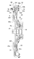
ロックアップ装置60は、フロントカバー2とタービン4との間に配置されており、両者を機械的に連結するための機構である。図2に示すように、ロックアップ装置60は、クラッチ部を構成するピストンプレート6と、ダンパ装置7とを有している。
ピストンプレート6は、クラッチ連結・遮断を行うための部材であり、中心孔が形成された円板状部材である。ピストンプレート6の内周縁には、軸方向エンジン側に延びる内周側筒状部6aが形成されている。内周側筒状部6aはタービンハブ16のエンジン側の外周面によって回転方向及び軸方向に移動可能に支持されている。なお、タービンハブ16のエンジン側の外周面には内周側筒状部6aの内周面に当接する環状のシールリング35が設けられている。これにより、ピストンプレート6の内周縁において軸方向のシールがされている。
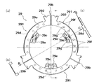
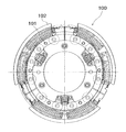
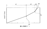
図2及び図3に示すように、ダンパ装置7は、リティニングプレート29と、ドリブンプレート30(出力プレートの一例)と、複数の外周側トーションスプリング31(第1スプリング部材の一例)と、サポートプレート32と、複数の内周側トーションスプリング33(第2スプリング部材の一例)と、を有している。なお、図2は図1のロックアップ装置60を抽出して示す図であり、図3はダンパ装置7の正面図である。図3では、一部の構成部材を省略して示しており、かつ所定角度(後述する図9の屈曲点P1までの角度)だけ捩じられた状態を示している。
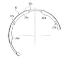
リティニングプレート29は、環状に形成され、ピストンプレート6の外周部のタービン4側に配置されている。リティニングプレート29は、図4に示すように、固定部29aと、複数の第1係合部29bと、複数のスプリング収容部29cと、複数のストッパ部29dと、を有している。なお、図4において、(a)は正面図であり、(b)はB矢視図、(c)はC矢視図である。
図5はドリブンプレート30の正面図である。ドリブンプレート30は、環状で且つ略円板状に形成され、リティニングプレート29のタービン側に配置されている。ドリブンプレート30は、内周部に形成された環状の固定部30aと、外周部に形成された複数の第2係合部30bと、固定部30aの外周側に形成された複数のスプリング作動部30cと、複数の中間ストッパ部30dと、最終ストッパ部30eを有している。
図6はサポートプレート32の正面部分図である。サポートプレート32は、環状に形成され、円板部32aと、複数の第2係合部32bと、外周支持部32cと、複数のストッパ部32dと、を有している。サポートプレート32は、リティニングプレート29及びドリブンプレート30に対して所定の角度範囲で相対回転可能に配置されている。
外周側トーションスプリング31は、この例では3つ設けられている。図3に示すように、各外周側トーションスプリング31は、低剛性コイルスプリング31aと、低剛性コイルスプリング31aより高い捩り剛性を有する高剛性コイルスプリング31bと、を有している。そして、前述のように、低剛性コイルスプリング31a及び高剛性コイルスプリング31bの対向する端面が第2係合部32bに当接しており、両スプリング31a,31bは直列的に作用する。なお、これらの両スプリング31a,31bはともに内側トーションスプリング33よりも自由長さが長い。
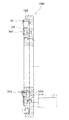
図7及び図8に示すように、まず治具100を準備する。治具100は、複数のピン101を有している。また、治具100は、環状の外壁部102を有している。この外壁部102の内周面に沿うように、サポートプレート32を配置する。なお、外壁部102の内径は、サポートプレート32の外径と略同じである。このため、サポートプレート32を外壁部102内に配置することで、サポートプレート32が位置決めされる。
エンジン回転数が低い領域では、ピストンプレート6のフロントカバー2側とタービン4側の油圧差によってピストンプレート6はタービン4側に移動している。このため、摩擦フェーシング36はフロントカバー2から離れ、ロックアップが解除されている。
以上、本発明の実施形態について説明したが、本発明はこれらに限定されるものではなく、本発明の趣旨を逸脱しない限りにおいて種々の変更が可能である。例えば、上記実施形態では、リティニングプレート29は3つの分割リティニングプレートに分割されているが、分割数はこれに限定されない。
7 :ダンパ装置
29 :リティニングプレート
291 :分割リティニングプレート
292 :分割係合部
29c :スプリング収容部
29e :延長部
29f :固定用取付孔
29g :治具用取付孔
30b :第2係合部
31 :外周側トーションスプリング(第1スプリング部材)
31a :低剛性コイルスプリング
31b :高剛性コイルスプリング
32 :サポートプレート
32b :第2係合部
33 :内側トーションスプリング(第2スプリング部材)
100 :治具
Claims (6)
- 環状のリティニングプレートと、
前記リティニングプレートに保持される複数の第1スプリング部材と、
前記スプリング部材を介して前記リティニングプレートと弾性的に連結する出力プレートと、
を備え、
前記リティニングプレートは、周方向において、複数の分割リティニングプレートに分割されている、
ダンパ装置。 - 前記各分割リティニングプレートは、治具用取付孔を有する、
請求項1に記載のダンパ装置。 - 複数の第2スプリングをさらに備え、
前記各分割リティニングプレートは、径方向内側に延びる延長部を有し、
前記延長部は、前記第2スプリング部材を収容するスプリング収容部と、前記治具用取付孔を有する、
請求項2に記載のダンパ装置。 - 前記リティニングプレートは、入力プレートに固定されるように構成されており、
前記各分割リティニングプレートは、前記入力プレートに固定されるための固定用取付孔を有する、
請求項2又は3に記載のダンパ装置。 - 前記各分割リティニングプレートは、周方向の両端部に、前記第1スプリング部材の端面に当接する分割係合部を有する、
請求項1から4のいずれかに記載のダンパ装置。 - 前記リティニングプレート及び前記出力プレートに対して相対回転可能であり、前記第1スプリング部材を径方向外側から支持するサポートプレートをさらに備え、
前記各第1スプリング部材は、低剛性コイルスプリングと、前記低剛性コイルスプリングよりも捩り剛性が高い高剛性コイルスプリングとを有しており、
前記サポートプレートは、周方向において前記低剛性コイルスプリングと前記高剛性コイルスプリングとの間に配置される第2係合部を有する、
請求項1から5のいずれかに記載のダンパ装置。
Priority Applications (3)
| Application Number | Priority Date | Filing Date | Title |
|---|---|---|---|
| JP2016081686A JP6714420B2 (ja) | 2016-04-15 | 2016-04-15 | ダンパ装置 |
| CN201710205892.2A CN107299973A (zh) | 2016-04-15 | 2017-03-30 | 阻尼器装置 |
| US15/480,600 US10451143B2 (en) | 2016-04-15 | 2017-04-06 | Damper device |
Applications Claiming Priority (1)
| Application Number | Priority Date | Filing Date | Title |
|---|---|---|---|
| JP2016081686A JP6714420B2 (ja) | 2016-04-15 | 2016-04-15 | ダンパ装置 |
Publications (2)
| Publication Number | Publication Date |
|---|---|
| JP2017190844A true JP2017190844A (ja) | 2017-10-19 |
| JP6714420B2 JP6714420B2 (ja) | 2020-06-24 |
Family
ID=60038721
Family Applications (1)
| Application Number | Title | Priority Date | Filing Date |
|---|---|---|---|
| JP2016081686A Active JP6714420B2 (ja) | 2016-04-15 | 2016-04-15 | ダンパ装置 |
Country Status (3)
| Country | Link |
|---|---|
| US (1) | US10451143B2 (ja) |
| JP (1) | JP6714420B2 (ja) |
| CN (1) | CN107299973A (ja) |
Cited By (1)
| Publication number | Priority date | Publication date | Assignee | Title |
|---|---|---|---|---|
| JP2023112328A (ja) * | 2022-02-01 | 2023-08-14 | 株式会社エクセディ | ダンパ装置及びその組立方法 |
Families Citing this family (3)
| Publication number | Priority date | Publication date | Assignee | Title |
|---|---|---|---|---|
| CN108253086A (zh) * | 2018-01-26 | 2018-07-06 | 淄博职业学院 | 一种汽车机械滑行减震减阻节能装置 |
| US11333217B2 (en) * | 2018-08-12 | 2022-05-17 | Schaeffler Technologies AG & Co. KG | Drive assembly including hub assembly extension |
| CN110001675B (zh) * | 2019-04-03 | 2020-07-14 | 株洲时代新材料科技股份有限公司 | 一种连接器 |
Citations (5)
| Publication number | Priority date | Publication date | Assignee | Title |
|---|---|---|---|---|
| JPS63128359U (ja) * | 1987-02-16 | 1988-08-22 | ||
| JPH0297754A (ja) * | 1988-10-05 | 1990-04-10 | Aisin Aw Co Ltd | 流体トルクコンバータのロックアップクラッチにおけるダンパ装置 |
| JPH0979344A (ja) * | 1995-09-14 | 1997-03-25 | Nsk Warner Kk | トルクコンバータ用のダンパー装置 |
| JP2002323111A (ja) * | 2001-04-23 | 2002-11-08 | Aisin Aw Co Ltd | 流体伝動装置 |
| JP2014202328A (ja) * | 2013-04-09 | 2014-10-27 | 株式会社エクセディ | トルクコンバータ用のロックアップ装置 |
Family Cites Families (7)
| Publication number | Priority date | Publication date | Assignee | Title |
|---|---|---|---|---|
| US1071946A (en) * | 1906-08-17 | 1913-09-02 | Morse Chain Co | Sprocket-wheel. |
| US2673475A (en) * | 1951-09-04 | 1954-03-30 | Ebsworth Richard Henry | Power transmission |
| JP2001304378A (ja) * | 2000-04-27 | 2001-10-31 | Nsk Warner Kk | ダンパー構造及びその構造のダンパーを有するトルクコンバータ用ロックアップクラッチ |
| EP2404074B1 (en) * | 2009-03-03 | 2014-01-01 | Litens Automotive Partnership | Decoupler featuring helical wrap clutch spring and coil damper springs |
| JP2013256963A (ja) | 2012-06-11 | 2013-12-26 | Exedy Corp | 流体式動力伝達装置 |
| DE102013210756A1 (de) * | 2013-06-10 | 2014-12-11 | Zf Friedrichshafen Ag | Wellfeder für einen Torsionsschwingungsdämpfer |
| CN106461048B (zh) * | 2014-05-30 | 2019-03-19 | 有能沛思株式会社 | 变矩器的锁定装置 |
-
2016
- 2016-04-15 JP JP2016081686A patent/JP6714420B2/ja active Active
-
2017
- 2017-03-30 CN CN201710205892.2A patent/CN107299973A/zh active Pending
- 2017-04-06 US US15/480,600 patent/US10451143B2/en not_active Expired - Fee Related
Patent Citations (5)
| Publication number | Priority date | Publication date | Assignee | Title |
|---|---|---|---|---|
| JPS63128359U (ja) * | 1987-02-16 | 1988-08-22 | ||
| JPH0297754A (ja) * | 1988-10-05 | 1990-04-10 | Aisin Aw Co Ltd | 流体トルクコンバータのロックアップクラッチにおけるダンパ装置 |
| JPH0979344A (ja) * | 1995-09-14 | 1997-03-25 | Nsk Warner Kk | トルクコンバータ用のダンパー装置 |
| JP2002323111A (ja) * | 2001-04-23 | 2002-11-08 | Aisin Aw Co Ltd | 流体伝動装置 |
| JP2014202328A (ja) * | 2013-04-09 | 2014-10-27 | 株式会社エクセディ | トルクコンバータ用のロックアップ装置 |
Cited By (3)
| Publication number | Priority date | Publication date | Assignee | Title |
|---|---|---|---|---|
| JP2023112328A (ja) * | 2022-02-01 | 2023-08-14 | 株式会社エクセディ | ダンパ装置及びその組立方法 |
| US12473961B2 (en) | 2022-02-01 | 2025-11-18 | Exedy Corporation | Damper device and method of assembling same |
| JP7792258B2 (ja) | 2022-02-01 | 2025-12-25 | 株式会社エクセディ | ダンパ装置及びその組立方法 |
Also Published As
| Publication number | Publication date |
|---|---|
| US10451143B2 (en) | 2019-10-22 |
| US20170299014A1 (en) | 2017-10-19 |
| JP6714420B2 (ja) | 2020-06-24 |
| CN107299973A (zh) | 2017-10-27 |
Similar Documents
| Publication | Publication Date | Title |
|---|---|---|
| JP5852701B2 (ja) | 流体式動力伝達装置 | |
| JP4755277B2 (ja) | トルクコンバータ用ロックアップ装置 | |
| JP4773553B2 (ja) | トルクコンバータ用ロックアップ装置 | |
| JP6117182B2 (ja) | 位相合わせリングに取り付けられる振り子式のおもりを含むトーショナルダンパ装置 | |
| CN103688075B (zh) | 离合器装置 | |
| US10253844B2 (en) | Torsional vibrating damping assembly, in particular mass damper unit | |
| JP2011122622A (ja) | トルクコンバータ用ロックアップ装置 | |
| JP2012077820A (ja) | 流体伝動装置 | |
| JP2017190844A (ja) | ダンパ装置 | |
| WO2014185148A1 (ja) | トルクコンバータのロックアップ装置 | |
| JP5688113B2 (ja) | トルクコンバータ用のロックアップ装置 | |
| US20150126290A1 (en) | Torsional vibration damper | |
| JP3874305B2 (ja) | いくつかの摩擦ステージを有するトーションダンパー | |
| JP2012077810A (ja) | 流体伝動装置およびその製造方法 | |
| CN113195940A (zh) | 液力变矩器的锁止装置 | |
| JP4956496B2 (ja) | 捩り振動低減装置 | |
| JP2019056461A (ja) | ダンパ装置 | |
| JP5684846B2 (ja) | トルクコンバータのロックアップ装置 | |
| JP2014206244A (ja) | トルクコンバータのロックアップ装置 | |
| KR101866937B1 (ko) | 차량용 토크 컨버터 | |
| JP2013245708A (ja) | スプリング固定装置 | |
| CN103797276B (zh) | 扭矩转换器的锁定装置 | |
| JP5598367B2 (ja) | 捩り振動低減装置 | |
| JP7199824B2 (ja) | トルクコンバータ振動吸収装置 | |
| JP2006177418A (ja) | 流体式トルク伝達装置のロックアップ装置 |
Legal Events
| Date | Code | Title | Description |
|---|---|---|---|
| A621 | Written request for application examination |
Free format text: JAPANESE INTERMEDIATE CODE: A621 Effective date: 20190214 |
|
| A977 | Report on retrieval |
Free format text: JAPANESE INTERMEDIATE CODE: A971007 Effective date: 20191206 |
|
| A131 | Notification of reasons for refusal |
Free format text: JAPANESE INTERMEDIATE CODE: A131 Effective date: 20191217 |
|
| A521 | Request for written amendment filed |
Free format text: JAPANESE INTERMEDIATE CODE: A523 Effective date: 20200130 |
|
| TRDD | Decision of grant or rejection written | ||
| A01 | Written decision to grant a patent or to grant a registration (utility model) |
Free format text: JAPANESE INTERMEDIATE CODE: A01 Effective date: 20200526 |
|
| A61 | First payment of annual fees (during grant procedure) |
Free format text: JAPANESE INTERMEDIATE CODE: A61 Effective date: 20200605 |
|
| R150 | Certificate of patent or registration of utility model |
Ref document number: 6714420 Country of ref document: JP Free format text: JAPANESE INTERMEDIATE CODE: R150 |
|
| R250 | Receipt of annual fees |
Free format text: JAPANESE INTERMEDIATE CODE: R250 |