JP2017190844A - Damper gear - Google Patents
Damper gear Download PDFInfo
- Publication number
- JP2017190844A JP2017190844A JP2016081686A JP2016081686A JP2017190844A JP 2017190844 A JP2017190844 A JP 2017190844A JP 2016081686 A JP2016081686 A JP 2016081686A JP 2016081686 A JP2016081686 A JP 2016081686A JP 2017190844 A JP2017190844 A JP 2017190844A
- Authority
- JP
- Japan
- Prior art keywords
- plate
- retaining
- spring
- retaining plate
- divided
- Prior art date
- Legal status (The legal status is an assumption and is not a legal conclusion. Google has not performed a legal analysis and makes no representation as to the accuracy of the status listed.)
- Granted
Links
Images


Classifications
-
- F—MECHANICAL ENGINEERING; LIGHTING; HEATING; WEAPONS; BLASTING
- F16—ENGINEERING ELEMENTS AND UNITS; GENERAL MEASURES FOR PRODUCING AND MAINTAINING EFFECTIVE FUNCTIONING OF MACHINES OR INSTALLATIONS; THERMAL INSULATION IN GENERAL
- F16H—GEARING
- F16H41/00—Rotary fluid gearing of the hydrokinetic type
- F16H41/24—Details
-
- F—MECHANICAL ENGINEERING; LIGHTING; HEATING; WEAPONS; BLASTING
- F16—ENGINEERING ELEMENTS AND UNITS; GENERAL MEASURES FOR PRODUCING AND MAINTAINING EFFECTIVE FUNCTIONING OF MACHINES OR INSTALLATIONS; THERMAL INSULATION IN GENERAL
- F16F—SPRINGS; SHOCK-ABSORBERS; MEANS FOR DAMPING VIBRATION
- F16F15/00—Suppression of vibrations in systems; Means or arrangements for avoiding or reducing out-of-balance forces, e.g. due to motion
- F16F15/10—Suppression of vibrations in rotating systems by making use of members moving with the system
- F16F15/12—Suppression of vibrations in rotating systems by making use of members moving with the system using elastic members or friction-damping members, e.g. between a rotating shaft and a gyratory mass mounted thereon
- F16F15/121—Suppression of vibrations in rotating systems by making use of members moving with the system using elastic members or friction-damping members, e.g. between a rotating shaft and a gyratory mass mounted thereon using springs as elastic members, e.g. metallic springs
- F16F15/123—Wound springs
- F16F15/12353—Combinations of dampers, e.g. with multiple plates, multiple spring sets, i.e. complex configurations
- F16F15/1236—Combinations of dampers, e.g. with multiple plates, multiple spring sets, i.e. complex configurations resulting in a staged spring characteristic, e.g. with multiple intermediate plates
- F16F15/12366—Combinations of dampers, e.g. with multiple plates, multiple spring sets, i.e. complex configurations resulting in a staged spring characteristic, e.g. with multiple intermediate plates acting on multiple sets of springs
-
- F—MECHANICAL ENGINEERING; LIGHTING; HEATING; WEAPONS; BLASTING
- F16—ENGINEERING ELEMENTS AND UNITS; GENERAL MEASURES FOR PRODUCING AND MAINTAINING EFFECTIVE FUNCTIONING OF MACHINES OR INSTALLATIONS; THERMAL INSULATION IN GENERAL
- F16F—SPRINGS; SHOCK-ABSORBERS; MEANS FOR DAMPING VIBRATION
- F16F15/00—Suppression of vibrations in systems; Means or arrangements for avoiding or reducing out-of-balance forces, e.g. due to motion
- F16F15/10—Suppression of vibrations in rotating systems by making use of members moving with the system
- F16F15/12—Suppression of vibrations in rotating systems by making use of members moving with the system using elastic members or friction-damping members, e.g. between a rotating shaft and a gyratory mass mounted thereon
- F16F15/121—Suppression of vibrations in rotating systems by making use of members moving with the system using elastic members or friction-damping members, e.g. between a rotating shaft and a gyratory mass mounted thereon using springs as elastic members, e.g. metallic springs
- F16F15/123—Wound springs
- F16F15/1232—Wound springs characterised by the spring mounting
-
- F—MECHANICAL ENGINEERING; LIGHTING; HEATING; WEAPONS; BLASTING
- F16—ENGINEERING ELEMENTS AND UNITS; GENERAL MEASURES FOR PRODUCING AND MAINTAINING EFFECTIVE FUNCTIONING OF MACHINES OR INSTALLATIONS; THERMAL INSULATION IN GENERAL
- F16F—SPRINGS; SHOCK-ABSORBERS; MEANS FOR DAMPING VIBRATION
- F16F2228/00—Functional characteristics, e.g. variability, frequency-dependence
- F16F2228/06—Stiffness
- F16F2228/066—Variable stiffness
-
- F—MECHANICAL ENGINEERING; LIGHTING; HEATING; WEAPONS; BLASTING
- F16—ENGINEERING ELEMENTS AND UNITS; GENERAL MEASURES FOR PRODUCING AND MAINTAINING EFFECTIVE FUNCTIONING OF MACHINES OR INSTALLATIONS; THERMAL INSULATION IN GENERAL
- F16F—SPRINGS; SHOCK-ABSORBERS; MEANS FOR DAMPING VIBRATION
- F16F2230/00—Purpose; Design features
- F16F2230/0005—Attachment, e.g. to facilitate mounting onto confer adjustability
-
- F—MECHANICAL ENGINEERING; LIGHTING; HEATING; WEAPONS; BLASTING
- F16—ENGINEERING ELEMENTS AND UNITS; GENERAL MEASURES FOR PRODUCING AND MAINTAINING EFFECTIVE FUNCTIONING OF MACHINES OR INSTALLATIONS; THERMAL INSULATION IN GENERAL
- F16F—SPRINGS; SHOCK-ABSORBERS; MEANS FOR DAMPING VIBRATION
- F16F2232/00—Nature of movement
- F16F2232/02—Rotary
-
- F—MECHANICAL ENGINEERING; LIGHTING; HEATING; WEAPONS; BLASTING
- F16—ENGINEERING ELEMENTS AND UNITS; GENERAL MEASURES FOR PRODUCING AND MAINTAINING EFFECTIVE FUNCTIONING OF MACHINES OR INSTALLATIONS; THERMAL INSULATION IN GENERAL
- F16F—SPRINGS; SHOCK-ABSORBERS; MEANS FOR DAMPING VIBRATION
- F16F2236/00—Mode of stressing of basic spring or damper elements or devices incorporating such elements
- F16F2236/08—Torsion
-
- F—MECHANICAL ENGINEERING; LIGHTING; HEATING; WEAPONS; BLASTING
- F16—ENGINEERING ELEMENTS AND UNITS; GENERAL MEASURES FOR PRODUCING AND MAINTAINING EFFECTIVE FUNCTIONING OF MACHINES OR INSTALLATIONS; THERMAL INSULATION IN GENERAL
- F16H—GEARING
- F16H45/00—Combinations of fluid gearings for conveying rotary motion with couplings or clutches
- F16H45/02—Combinations of fluid gearings for conveying rotary motion with couplings or clutches with mechanical clutches for bridging a fluid gearing of the hydrokinetic type
- F16H2045/0221—Combinations of fluid gearings for conveying rotary motion with couplings or clutches with mechanical clutches for bridging a fluid gearing of the hydrokinetic type with damping means
- F16H2045/0226—Combinations of fluid gearings for conveying rotary motion with couplings or clutches with mechanical clutches for bridging a fluid gearing of the hydrokinetic type with damping means comprising two or more vibration dampers
-
- F—MECHANICAL ENGINEERING; LIGHTING; HEATING; WEAPONS; BLASTING
- F16—ENGINEERING ELEMENTS AND UNITS; GENERAL MEASURES FOR PRODUCING AND MAINTAINING EFFECTIVE FUNCTIONING OF MACHINES OR INSTALLATIONS; THERMAL INSULATION IN GENERAL
- F16H—GEARING
- F16H45/00—Combinations of fluid gearings for conveying rotary motion with couplings or clutches
- F16H45/02—Combinations of fluid gearings for conveying rotary motion with couplings or clutches with mechanical clutches for bridging a fluid gearing of the hydrokinetic type
Landscapes
- Engineering & Computer Science (AREA)
- General Engineering & Computer Science (AREA)
- Mechanical Engineering (AREA)
- Physics & Mathematics (AREA)
- Acoustics & Sound (AREA)
- Aviation & Aerospace Engineering (AREA)
- Mechanical Operated Clutches (AREA)
- Springs (AREA)
Abstract
Description
本発明は、ダンパ装置に関するものである。 The present invention relates to a damper device.
トルクコンバータは、フロントカバーからタービンに直接トルクを伝達するためのロックアップ装置を有している。そして、ロックアップ装置は、エンジンの振動を減衰するためのダンパ装置を有している。ダンパ装置は、トーションスプリングと、これを保持するリティニングプレートと、ドリブンプレートとを有している(特許文献1参照)。 The torque converter has a lock-up device for transmitting torque directly from the front cover to the turbine. The lockup device has a damper device for attenuating engine vibration. The damper device includes a torsion spring, a retaining plate that holds the torsion spring, and a driven plate (see Patent Document 1).
上述したようなダンパ装置において、低コスト化が要望されている。本発明の課題は、低コスト化が可能なダンパ装置を提供することにある。 In the damper device as described above, cost reduction is desired. An object of the present invention is to provide a damper device capable of reducing the cost.
本発明のある側面に係るダンパ装置は、環状のリティニングプレートと、複数のスプリング部材と、出力プレートと、を備えている。各スプリング部材は、リティニングプレートに保持される。出力プレートは、スプリング部材を介してリティニングプレートと弾性的に連結する。リティニングプレートは、周方向において、複数の分割リティニングプレートに分割されている。 A damper device according to an aspect of the present invention includes an annular retaining plate, a plurality of spring members, and an output plate. Each spring member is held by the retaining plate. The output plate is elastically connected to the retaining plate via a spring member. The retaining plate is divided into a plurality of divided retaining plates in the circumferential direction.
リティニングプレートは環状であるため、従来、リティニングプレートは、円板状の部材の中央を繰り抜いて形成されていた。そして、この繰り抜かれた部分は端材として廃棄されていた。これに対して、本発明に係るリティニングプレートは、複数の分割リティニングプレートに分割されているため、各分割リティニングプレートをそれぞれ板状の部材から形成することができる。このため、従来のような端材が発生することがなく、低コスト化が可能となる。 Since the retaining plate has an annular shape, the retaining plate is conventionally formed by pulling out the center of a disk-shaped member. And the part pulled out was discarded as a scrap. On the other hand, since the retaining plate according to the present invention is divided into a plurality of divided retaining plates, each divided retaining plate can be formed from a plate-like member. For this reason, there is no occurrence of the end material as in the prior art, and the cost can be reduced.
また、従来、リティニングプレートの一部に傷や打痕のような不良が発生した場合、そのリティニングプレート全体を廃棄していた。これに対して、本発明に係るリティニングプレートは、複数の分割リティニングプレートに分割されているため、一部に傷や打痕のような不良が発生した場合、その不良がある分割リティニングプレートのみを廃棄すればよく、リティニングプレート全体を廃棄する必要が無い。このため、低コスト化が可能である。 Conventionally, when a defect such as a scratch or a dent occurs in a part of the retaining plate, the entire retaining plate has been discarded. On the other hand, since the retaining plate according to the present invention is divided into a plurality of divided retaining plates, when a defect such as a scratch or a dent occurs in a part, the divided retaining plate having the defect is present. It is only necessary to discard the plate, and it is not necessary to discard the entire retaining plate. For this reason, cost reduction is possible.
好ましくは、各分割リティニングプレートは、治具用取付孔を有する。この構成によれば、スプリング部材が組まれた各分割リティニングプレートを治具に取り付けることができる。この治具にセットされた状態で、各分割リティニングプレートを、ピストンプレートなどの他の部材に取り付けることができる。このため、スプリング部材の張力が各分割リティニングプレートに作用していても、各分割リティニングプレートが互いに適切な位置に配置された状態を維持することができる。 Preferably, each divided retaining plate has a jig mounting hole. According to this structure, each division | segmentation retaining plate with which the spring member was assembled can be attached to a jig | tool. Each split retaining plate can be attached to another member such as a piston plate while being set in the jig. For this reason, even if the tension | tensile_strength of a spring member is acting on each division | segmentation retaining plate, the state by which each division | segmentation retaining plate was arrange | positioned in the mutually suitable position can be maintained.
好ましくは、ダンパ装置は、複数の第2スプリングをさらに備える。各分割リティニングプレートは、径方向内側に延びる延長部を有する。延長部は、第2スプリング部材を収容するスプリング収容部と、治具用取付孔を有する。 Preferably, the damper device further includes a plurality of second springs. Each divided retaining plate has an extension extending radially inward. The extension portion has a spring accommodating portion that accommodates the second spring member, and a jig mounting hole.
好ましくは、リティニングプレートは、入力プレートに固定されるように構成されている。そして、各分割リティニングプレートは、入力プレートに固定されるための固定用取付孔を有する。この構成によれば、固定用取付孔を用いて、各分割リティニングプレートを、入力プレートに対してリベットなどで固定することができる。 Preferably, the retaining plate is configured to be fixed to the input plate. Each divided retaining plate has a fixing mounting hole for fixing to the input plate. According to this configuration, each divided retaining plate can be fixed to the input plate with a rivet or the like using the fixing mounting hole.
好ましくは、各分割リティニングプレートは、周方向の両端部に、スプリング部材の端面に当接する第1係合部を有する。 Preferably, each divided retaining plate has a first engagement portion that is in contact with the end face of the spring member at both ends in the circumferential direction.
好ましくは、ダンパ装置は、サポートプレートをさらに備える。サポートプレートは、リティニングプレート及び出力プレートに対して相対回転可能である。また、サポートプレートは、スプリング部材を径方向外側から支持する。各スプリング部材は、低剛性コイルスプリングと高剛性コイルスプリングとを有している。サポートプレートは、周方向において、低剛性コイルスプリングと高剛性コイルスプリングとの間に配置される第2係合部を有する。 Preferably, the damper device further includes a support plate. The support plate is rotatable relative to the retaining plate and the output plate. The support plate supports the spring member from the outside in the radial direction. Each spring member has a low rigidity coil spring and a high rigidity coil spring. The support plate has a second engagement portion disposed between the low-rigidity coil spring and the high-rigidity coil spring in the circumferential direction.
本発明に係るダンパ装置によれば、低コスト化が可能となる。 The damper device according to the present invention can reduce the cost.
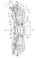
図1は、本発明の一実施形態としてのダンパ装置を含むトルクコンバータ1の断面部分図である。図1の左側にはエンジン(図示せず)が配置され、図の右側にトランスミッション(図示せず)が配置されている。図1に示すO−Oは、トルクコンバータ及びダンパ装置の回転軸Oである。以下の説明において、周方向とは、回転軸Oを中心とする円の周方向を示し、径方向とは、回転軸Oを中心とする円の径方向を示す。
FIG. 1 is a partial sectional view of a
[トルクコンバータ]
トルクコンバータ1は、図示しないフレキシブルプレートによってエンジン側の部材に連結され、エンジンのクランクシャフトからトランスミッションの入力シャフトにトルクを伝達するための装置である。トルクコンバータ1は、フロントカバー2と、インペラ3と、タービン4と、ステータ5と、ピストンプレート6と、ダンパ装置7と、を備えている。
[Torque converter]
The
[フロントカバー]
フロントカバー2は、円板状の部材であり、内周端にはセンターボス2aが設けられ、外周部には、軸方向トランスミッション側に延びる外周側筒状部2bが形成されている。センターボス2aは、軸方向に延びる円筒形状の部材であり、クランクシャフトの中心孔内に挿入されている。フロントカバー2の外周側には、周方向に等間隔で複数のボルト8が固定されている。このボルト8に螺合するナットによって、フレキシブルプレートの外周部がフロントカバー2に固定される。
[front cover]
The
[インペラ]
インペラ3は、主に、インペラシェル10と、その内側に固定された複数のインペラブレード11と、インペラシェル10の内周部に固定されたインペラハブ12とから構成されている。インペラシェル10の外周縁がフロントカバー2の外周側筒状部2bの先端に溶接されている。
[Impeller]
The
[タービン]
タービン4はインペラ3に対して軸方向に対向して配置されている。タービン4は、主に、タービンシェル14と、タービンシェル14のインペラ側の面に固定された複数のタービンブレード15と、タービンシェル14の内周縁に固定されたタービンハブ16とから構成されている。タービンシェル14とタービンハブ16とは複数のリベット17によって固定されている。また、タービンハブ16の内周面には、トランスミッションの入力シャフトに係合するスプラインが形成されている。
[Turbine]
The
[ステータ]
ステータ5は、タービン4からインペラ3に戻る作動油の流れを整流するための機構であり、インペラ3の内周部とタービン4の内周部と間に配置されている。ステータ5は、主に、環状のステータシェル20と、ステータシェル20の外周面に設けられた複数のステータブレード21とから構成されている。ステータシェル20はワンウェイクラッチ22を介して筒状の固定シャフト(図示しない)に支持されている。固定シャフトはトランスミッションの入力シャフトの外周面とインペラハブ12の内周面との間を延びている。
[Stator]
The
フロントカバー2の内周部とタービンハブ16との軸方向間にはスラストワッシャ24が配置されている。また、タービンハブ16とステータ5の内周部との間、及びステータ5とインペラ3との軸方向間には、それぞれスラストベアリング25,26が配置されている。
A
[ロックアップ装置]
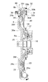
ロックアップ装置60は、フロントカバー2とタービン4との間に配置されており、両者を機械的に連結するための機構である。図2に示すように、ロックアップ装置60は、クラッチ部を構成するピストンプレート6と、ダンパ装置7とを有している。
[Lock-up device]
The
[ピストンプレート]
ピストンプレート6は、クラッチ連結・遮断を行うための部材であり、中心孔が形成された円板状部材である。ピストンプレート6の内周縁には、軸方向エンジン側に延びる内周側筒状部6aが形成されている。内周側筒状部6aはタービンハブ16のエンジン側の外周面によって回転方向及び軸方向に移動可能に支持されている。なお、タービンハブ16のエンジン側の外周面には内周側筒状部6aの内周面に当接する環状のシールリング35が設けられている。これにより、ピストンプレート6の内周縁において軸方向のシールがされている。
[Piston plate]
The
ピストンプレート6の外周側には摩擦連結部6bが形成されている。摩擦連結部6bは、半径方向に所定の長さを有する環状部分であり、フロントカバー2側の面には環状の摩擦フェーシング36が接着されている。このように、ピストンプレート6とフロントカバー2の平坦な摩擦面とによって、ダンパ装置7のクラッチ部が構成されている。
A
[ダンパ装置]
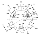
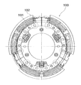
図2及び図3に示すように、ダンパ装置7は、リティニングプレート29と、ドリブンプレート30(出力プレートの一例)と、複数の外周側トーションスプリング31(第1スプリング部材の一例)と、サポートプレート32と、複数の内周側トーションスプリング33(第2スプリング部材の一例)と、を有している。なお、図2は図1のロックアップ装置60を抽出して示す図であり、図3はダンパ装置7の正面図である。図3では、一部の構成部材を省略して示しており、かつ所定角度(後述する図9の屈曲点P1までの角度)だけ捩じられた状態を示している。
[Damper device]
As shown in FIGS. 2 and 3, the
[リティニングプレート]
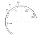
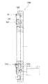
リティニングプレート29は、環状に形成され、ピストンプレート6の外周部のタービン4側に配置されている。リティニングプレート29は、図4に示すように、固定部29aと、複数の第1係合部29bと、複数のスプリング収容部29cと、複数のストッパ部29dと、を有している。なお、図4において、(a)は正面図であり、(b)はB矢視図、(c)はC矢視図である。
[Retaining plate]
The retaining
図2に示すように、固定部29aは、ピストンプレート6の側面に当接し、リベット37によってピストンプレート6に固定されている。詳細には、図4に示すように、リティニングプレート29は、複数の固定用取付孔29fを有している。各固定用取付孔29fは、固定部29aにおいて、周方向に間隔をあけて形成されている。この固定用取付孔29fを用いて、リティニングプレート29をピストンプレート6にリベットで固定する。
As shown in FIG. 2, the fixing
第1係合部29bは、固定部29aから外周側に延び、周方向に等角度間隔で設けられている。図4(b)に示すように、第1係合部29bは、外周端部の一部(周方向の両端部)がタービン側に折り曲げられている。そして、第1係合部29bの周方向の両端面が外周側トーションスプリング31の周方向の端面に当接可能である。
The first
スプリング収容部29cは固定部29aから径方向内側に延びた複数の延長部29eに形成されている。延長部29eは、周方向において2つの第1係合部29bの間に等角度間隔で形成されている。スプリング収容部29cは延長部29eの一部をタービン側に切り起こして形成された開口部である。このスプリング収容部29cに内周側トーションスプリング33が収容されている。
The
ストッパ部29dは、図4(c)に示すように、周方向においてスプリング収容部29cと同じ位置に、外周端の一部をタービン側に折り曲げて形成されている。
As shown in FIG. 4C, the
リティニングプレート29は、周方向において、複数の分割リティニングプレート291に分割されている。リティニングプレート29は、第1係合部29bにおいて分割されている。すなわち、1つの第1係合部29bは、隣接する一対の分割係合部292によって構成されている。なお、本実施形態では、リティニングプレート29は、3つの分割リティニングプレート291に分割されている。
The retaining
分割リティニングプレート291は、複数の治具用取付孔29gを有している。各治具用取付孔29gは、固定部29a及び延長部29eに形成されている。固定部29aに形成された治具用取付孔29gは、周方向において、互いに間隔をあけて配置されている。また、この各治具用取付孔29gは、周方向において、上述した固定用取付孔29fの間に形成されている。
The divided retaining
延長部29eに形成された治具用取付孔29gは、固定用取付孔29fよりも径方向内側に配置されている。本実施形態では、2つの治具用取付孔29gが延長部29eに形成されており、この1対の治具用取付孔29gは、周方向においてスプリング収容部29cを挟むように配置されている。
The
分割リティニングプレート291は、周方向の両端部に、上述した分割係合部292を有している。隣接する一対の分割係合部292が、第1係合部29bを構成する。各分割リティニングプレート291は、互いに同じ形状である。各分割リティニングプレート291は、上述したスプリング収容部29c、ストッパ部29d、及び延長部29eを有している。
The divided retaining
[ドリブンプレート]
図5はドリブンプレート30の正面図である。ドリブンプレート30は、環状で且つ略円板状に形成され、リティニングプレート29のタービン側に配置されている。ドリブンプレート30は、内周部に形成された環状の固定部30aと、外周部に形成された複数の第2係合部30bと、固定部30aの外周側に形成された複数のスプリング作動部30cと、複数の中間ストッパ部30dと、最終ストッパ部30eを有している。
[Driven plate]
FIG. 5 is a front view of the driven
固定部30aは、図2に示すように、タービンシェル14とともにリベット17によりタービンハブ16に固定されている。複数の第2係合部30bは、2個1組の第2係合部30bが周方向に等角度間隔で配置されている。各第2係合部30bは、フロントカバー2側に折り曲げて形成されている。
As shown in FIG. 2, the fixed
スプリング作動部30cは、周方向に延びる円弧状の複数の開口である。このスプリング作動部30cは、周方向において、第2係合部30bが形成されていない領域に形成されている。スプリング作動部30cには、リティニングプレート29のスプリング収容部29c及び内周側トーションスプリング33の一部が収容可能である。また、スプリング作動部30cの周方向の両端には、フロントカバー2側に突出する突出部30f(図2参照)が形成されている。この突出部30fは内周側トーションスプリング33の周方向の端面に当接可能である。
The
中間ストッパ部30dは、1組の第2係合部30bの周方向間に形成され、タービン4側に折り曲げて形成されている。また、最終ストッパ部30eは、1対の第2係合部30bを挟むように形成されており、外周側に突出して形成されている。
The
[サポートプレート]
図6はサポートプレート32の正面部分図である。サポートプレート32は、環状に形成され、円板部32aと、複数の第2係合部32bと、外周支持部32cと、複数のストッパ部32dと、を有している。サポートプレート32は、リティニングプレート29及びドリブンプレート30に対して所定の角度範囲で相対回転可能に配置されている。
[Support plate]
FIG. 6 is a partial front view of the
円板部32aは、外周側トーションスプリング31のタービン4側に配置され、ピストンとともに外周側トーションスプリング31の軸方向の移動を規制している。複数の第2係合部32bは、円板部32aから内周側に延び、さらにフロントカバー2側に延びて先端が外周側に折り曲げられている。この第2係合部32bを挟んで、1対の外周側のトーションスプリング31が配置されている。外周支持部32cは、円板部32aの外周部からフロントカバー2側に延びて形成され、外周側トーションスプリング31の径方向への移動を規制している。ストッパ部32dは、円板部32aの内周部をさらに内周側に延長して形成されたものであり、第2係合部32bから一方向に所定の角度隔てて配置されている。
The
[外周側トーションスプリング]
外周側トーションスプリング31は、この例では3つ設けられている。図3に示すように、各外周側トーションスプリング31は、低剛性コイルスプリング31aと、低剛性コイルスプリング31aより高い捩り剛性を有する高剛性コイルスプリング31bと、を有している。そして、前述のように、低剛性コイルスプリング31a及び高剛性コイルスプリング31bの対向する端面が第2係合部32bに当接しており、両スプリング31a,31bは直列的に作用する。なお、これらの両スプリング31a,31bはともに内側トーションスプリング33よりも自由長さが長い。
[Outer side torsion spring]
In this example, three outer peripheral torsion springs 31 are provided. As shown in FIG. 3, each outer peripheral
[ロックアップ装置の組み立て方法]
図7及び図8に示すように、まず治具100を準備する。治具100は、複数のピン101を有している。また、治具100は、環状の外壁部102を有している。この外壁部102の内周面に沿うように、サポートプレート32を配置する。なお、外壁部102の内径は、サポートプレート32の外径と略同じである。このため、サポートプレート32を外壁部102内に配置することで、サポートプレート32が位置決めされる。
[Assembly method of lock-up device]
As shown in FIGS. 7 and 8, first, a
次に、外周側トーションスプリング31をサポートプレート32に沿って配置する。そして、各分割リティニングプレート291を治具100にセットする。詳細には、分割リティニングプレート291の治具用取付孔29gに治具100のピン101を刺すことによって、分割リティニングプレート291が位置決めされる。
Next, the outer peripheral
以上のように、サポートプレート32及び各分割リティニングプレート291を治具100にセットした状態で、この上からピストンプレート6を載置する。そして、リベット37によって、各分割リティニングプレート291をピストンプレート6に固定する。なお、治具100は、リベット37を配置するための貫通孔103を有している。次に、このアセンブリを治具100から取り外してトルクコンバータに組み込む。
As described above, with the
[動作]
エンジン回転数が低い領域では、ピストンプレート6のフロントカバー2側とタービン4側の油圧差によってピストンプレート6はタービン4側に移動している。このため、摩擦フェーシング36はフロントカバー2から離れ、ロックアップが解除されている。
[Operation]
In the region where the engine speed is low, the
エンジン回転数が上昇すると、前記とは逆にピストンプレート6がフロントカバー2側に移動させられ、摩擦フェーシング36がフロントカバー2の摩擦面に押し付けられる。この結果、フロントカバー2のトルクは、ピストンプレート6から、リティニングプレート29及び外周側及び内周側のトーションスプリング31,33を介してドリブンプレート30に伝達される。さらに、トルクは、ドリブンプレート30からタービン4に伝達される。
When the engine speed increases, the
以上のロックアップ状態においては、外周側及び内周側のトーションスプリング31,33によって、捩り振動が吸収・減衰される。以下、この点について説明する。 In the above lock-up state, torsional vibrations are absorbed and damped by the outer and inner torsion springs 31 and 33. Hereinafter, this point will be described.
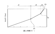
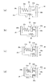
図9は、各トーションスプリング31,33が作動したときの捩り特性を示す図である。また、図10は、捩り特性の各段階で、各トーションスプリング31,33が作動したときのモデル図である。 FIG. 9 is a diagram showing torsional characteristics when the torsion springs 31 and 33 are operated. FIG. 10 is a model diagram when the torsion springs 31 and 33 are actuated at each stage of torsional characteristics.
フロントカバー2から捩り振動が入力され、リティニングプレート29とドリブンプレート30との間に相対回転が生じると、まず、外周側トーションスプリング31がリティニングプレート29とドリブンプレート30との間で回転方向に圧縮される。この状態(図9のJ1で示す領域及び図10(a)で示す状態)では、低剛性コイルスプリング31aのみが圧縮される。なお、低剛性コイルスプリング31a及び高剛性コイルスプリング31bの剛性の設定によっては、J1領域で高剛性コイルスプリング31bが圧縮を始める場合もある。
When torsional vibration is input from the
具体的には、低剛性及び高剛性コイルスプリング31a,31bは、リティニングプレート29の第1係合部29bとドリブンプレート30の第2係合部30bとの間で回転方向に圧縮される。このとき、サポートプレート32は、両スプリング31a,31bとともに回転し、リティニングプレート29及びドリブンプレート30と相対回転する。
Specifically, the low-rigidity and high-rigidity coil springs 31 a and 31 b are compressed in the rotational direction between the
そして、捩り角度θが大きくなると、低剛性コイルスプリング31aが線間密着する前に、サポートプレート32のストッパ部32dがドリブンプレート30の中間ストッパ部30dに当接し、サポートプレート32とドリブンプレート30との相対回転が禁止される。この状態が、図9における第1屈曲点P1に相当する。また、図3はこの状態を示しており、図10では(b)に相当する。
When the torsion angle θ increases, the
この第1屈曲点P1からさらに捩じり角度θが大きくなると、サポートプレート32とドリブンプレート30との相対回転が禁止されているので、高剛性コイルスプリング31bのみが圧縮される。この状態が、図9におけるJ2の領域である。図10では(b)から(c)に移行する状態である。
When the twisting angle θ further increases from the first bending point P1, the relative rotation between the
さらに捩り角度θが大きくなると、リティニングプレート29のスプリング収容部29cに収容された内周側トーションスプリング33がドリブンプレート30の開口(スプリング作動部30c)の端面の突出部30fに当接し(図9の第2屈曲点P2及び図10(c)に相当)、この時点から内周側トーションスプリング33の圧縮が開始される。
When the torsion angle θ is further increased, the inner
第2屈曲点P2移行は、高剛性コイルスプリング31b及び内周側トーションスプリング33が圧縮される。この状態が、図9におけるJ3の領域であり、図10(d)に相当している。そして、最終的には、リティニングプレート29のストッパ部29dがドリブンプレート30の最終ストッパ部30eに当接し、リティニングプレート29とドリブンプレート30との相対回転が禁止される(図9のP3)。
In the transition to the second bending point P2, the high-
[変形例]
以上、本発明の実施形態について説明したが、本発明はこれらに限定されるものではなく、本発明の趣旨を逸脱しない限りにおいて種々の変更が可能である。例えば、上記実施形態では、リティニングプレート29は3つの分割リティニングプレートに分割されているが、分割数はこれに限定されない。
[Modification]
As mentioned above, although embodiment of this invention was described, this invention is not limited to these, A various change is possible unless it deviates from the meaning of this invention. For example, in the above embodiment, the retaining
また、上記実施形態では、治具用取付孔29gは、固定部29aと延長部29eに形成されているが、どちらか一方のみに形成されていてもよい。また、この治具用取付孔29gの数は、上記実施形態の数に限定されない。
Further, in the above embodiment, the
6 :ピストンプレート
7 :ダンパ装置
29 :リティニングプレート
291 :分割リティニングプレート
292 :分割係合部
29c :スプリング収容部
29e :延長部
29f :固定用取付孔
29g :治具用取付孔
30b :第2係合部
31 :外周側トーションスプリング(第1スプリング部材)
31a :低剛性コイルスプリング
31b :高剛性コイルスプリング
32 :サポートプレート
32b :第2係合部
33 :内側トーションスプリング(第2スプリング部材)
100 :治具
6: Piston plate 7: Damper device 29: Retaining plate 291: Divided retaining plate 292: Divided engaging
31a: Low
100: Jig
Claims (6)
前記リティニングプレートに保持される複数の第1スプリング部材と、
前記スプリング部材を介して前記リティニングプレートと弾性的に連結する出力プレートと、
を備え、
前記リティニングプレートは、周方向において、複数の分割リティニングプレートに分割されている、
ダンパ装置。 An annular retaining plate;
A plurality of first spring members held by the retaining plate;
An output plate elastically coupled to the retaining plate via the spring member;
With
The retaining plate is divided into a plurality of divided retaining plates in the circumferential direction.
Damper device.
請求項1に記載のダンパ装置。 Each of the divided retaining plates has a jig mounting hole.
The damper device according to claim 1.
前記各分割リティニングプレートは、径方向内側に延びる延長部を有し、
前記延長部は、前記第2スプリング部材を収容するスプリング収容部と、前記治具用取付孔を有する、
請求項2に記載のダンパ装置。 A plurality of second springs;
Each of the divided retaining plates has an extension extending radially inward,
The extension portion includes a spring accommodating portion that accommodates the second spring member, and the jig mounting hole.
The damper device according to claim 2.
前記各分割リティニングプレートは、前記入力プレートに固定されるための固定用取付孔を有する、
請求項2又は3に記載のダンパ装置。 The retaining plate is configured to be fixed to an input plate;
Each of the divided retaining plates has a fixing mounting hole for fixing to the input plate.
The damper device according to claim 2 or 3.
請求項1から4のいずれかに記載のダンパ装置。 Each of the split retaining plates has split engagement portions that are in contact with the end surface of the first spring member at both ends in the circumferential direction.
The damper device according to any one of claims 1 to 4.
前記各第1スプリング部材は、低剛性コイルスプリングと、前記低剛性コイルスプリングよりも捩り剛性が高い高剛性コイルスプリングとを有しており、
前記サポートプレートは、周方向において前記低剛性コイルスプリングと前記高剛性コイルスプリングとの間に配置される第2係合部を有する、
請求項1から5のいずれかに記載のダンパ装置。 A support plate that is rotatable relative to the retaining plate and the output plate and supports the first spring member from the outside in the radial direction;
Each of the first spring members includes a low-rigidity coil spring and a high-rigidity coil spring having a higher torsional rigidity than the low-rigidity coil spring.
The support plate has a second engagement portion disposed between the low-rigidity coil spring and the high-rigidity coil spring in the circumferential direction.
The damper device according to any one of claims 1 to 5.
Priority Applications (3)
| Application Number | Priority Date | Filing Date | Title |
|---|---|---|---|
| JP2016081686A JP6714420B2 (en) | 2016-04-15 | 2016-04-15 | Damper device |
| CN201710205892.2A CN107299973A (en) | 2016-04-15 | 2017-03-30 | Damper device |
| US15/480,600 US10451143B2 (en) | 2016-04-15 | 2017-04-06 | Damper device |
Applications Claiming Priority (1)
| Application Number | Priority Date | Filing Date | Title |
|---|---|---|---|
| JP2016081686A JP6714420B2 (en) | 2016-04-15 | 2016-04-15 | Damper device |
Publications (2)
| Publication Number | Publication Date |
|---|---|
| JP2017190844A true JP2017190844A (en) | 2017-10-19 |
| JP6714420B2 JP6714420B2 (en) | 2020-06-24 |
Family
ID=60038721
Family Applications (1)
| Application Number | Title | Priority Date | Filing Date |
|---|---|---|---|
| JP2016081686A Active JP6714420B2 (en) | 2016-04-15 | 2016-04-15 | Damper device |
Country Status (3)
| Country | Link |
|---|---|
| US (1) | US10451143B2 (en) |
| JP (1) | JP6714420B2 (en) |
| CN (1) | CN107299973A (en) |
Cited By (1)
| Publication number | Priority date | Publication date | Assignee | Title |
|---|---|---|---|---|
| JP2023112328A (en) * | 2022-02-01 | 2023-08-14 | 株式会社エクセディ | Damper device and its assembly method |
Families Citing this family (3)
| Publication number | Priority date | Publication date | Assignee | Title |
|---|---|---|---|---|
| CN108253086A (en) * | 2018-01-26 | 2018-07-06 | 淄博职业学院 | A kind of automobile mechanical slides damping drag-reduction energy-saving device |
| US11333217B2 (en) * | 2018-08-12 | 2022-05-17 | Schaeffler Technologies AG & Co. KG | Drive assembly including hub assembly extension |
| CN110001675B (en) * | 2019-04-03 | 2020-07-14 | 株洲时代新材料科技股份有限公司 | A kind of interface unit |
Citations (5)
| Publication number | Priority date | Publication date | Assignee | Title |
|---|---|---|---|---|
| JPS63128359U (en) * | 1987-02-16 | 1988-08-22 | ||
| JPH0297754A (en) * | 1988-10-05 | 1990-04-10 | Aisin Aw Co Ltd | Damper device in lockup clutch for fluid torque converter |
| JPH0979344A (en) * | 1995-09-14 | 1997-03-25 | Nsk Warner Kk | Damper device for torque converter |
| JP2002323111A (en) * | 2001-04-23 | 2002-11-08 | Aisin Aw Co Ltd | Fluid transmission |
| JP2014202328A (en) * | 2013-04-09 | 2014-10-27 | 株式会社エクセディ | Lock-up device for torque converter |
Family Cites Families (7)
| Publication number | Priority date | Publication date | Assignee | Title |
|---|---|---|---|---|
| US1071946A (en) * | 1906-08-17 | 1913-09-02 | Morse Chain Co | Sprocket-wheel. |
| US2673475A (en) * | 1951-09-04 | 1954-03-30 | Ebsworth Richard Henry | Power transmission |
| JP2001304378A (en) * | 2000-04-27 | 2001-10-31 | Nsk Warner Kk | Damper structure and lockup clutch for torque converter having damper of the structure |
| EP2404074B1 (en) * | 2009-03-03 | 2014-01-01 | Litens Automotive Partnership | Decoupler featuring helical wrap clutch spring and coil damper springs |
| JP2013256963A (en) | 2012-06-11 | 2013-12-26 | Exedy Corp | Fluid type power transmission device |
| DE102013210756A1 (en) * | 2013-06-10 | 2014-12-11 | Zf Friedrichshafen Ag | Wave spring for a torsional vibration damper |
| CN106461048B (en) * | 2014-05-30 | 2019-03-19 | 有能沛思株式会社 | Torque Converter Locking Device |
-
2016
- 2016-04-15 JP JP2016081686A patent/JP6714420B2/en active Active
-
2017
- 2017-03-30 CN CN201710205892.2A patent/CN107299973A/en active Pending
- 2017-04-06 US US15/480,600 patent/US10451143B2/en not_active Expired - Fee Related
Patent Citations (5)
| Publication number | Priority date | Publication date | Assignee | Title |
|---|---|---|---|---|
| JPS63128359U (en) * | 1987-02-16 | 1988-08-22 | ||
| JPH0297754A (en) * | 1988-10-05 | 1990-04-10 | Aisin Aw Co Ltd | Damper device in lockup clutch for fluid torque converter |
| JPH0979344A (en) * | 1995-09-14 | 1997-03-25 | Nsk Warner Kk | Damper device for torque converter |
| JP2002323111A (en) * | 2001-04-23 | 2002-11-08 | Aisin Aw Co Ltd | Fluid transmission |
| JP2014202328A (en) * | 2013-04-09 | 2014-10-27 | 株式会社エクセディ | Lock-up device for torque converter |
Cited By (3)
| Publication number | Priority date | Publication date | Assignee | Title |
|---|---|---|---|---|
| JP2023112328A (en) * | 2022-02-01 | 2023-08-14 | 株式会社エクセディ | Damper device and its assembly method |
| US12473961B2 (en) | 2022-02-01 | 2025-11-18 | Exedy Corporation | Damper device and method of assembling same |
| JP7792258B2 (en) | 2022-02-01 | 2025-12-25 | 株式会社エクセディ | Damper device and assembly method thereof |
Also Published As
| Publication number | Publication date |
|---|---|
| US10451143B2 (en) | 2019-10-22 |
| US20170299014A1 (en) | 2017-10-19 |
| JP6714420B2 (en) | 2020-06-24 |
| CN107299973A (en) | 2017-10-27 |
Similar Documents
| Publication | Publication Date | Title |
|---|---|---|
| JP5852701B2 (en) | Fluid power transmission device | |
| JP4755277B2 (en) | Lock-up device for torque converter | |
| JP4773553B2 (en) | Lock-up device for torque converter | |
| JP6117182B2 (en) | Torsional damper device with pendulum weight attached to phasing ring | |
| CN103688075B (en) | clutch device | |
| US10253844B2 (en) | Torsional vibrating damping assembly, in particular mass damper unit | |
| JP2011122622A (en) | Lock-up device for torque converter | |
| JP2012077820A (en) | Hydraulic transmission | |
| JP2017190844A (en) | Damper gear | |
| WO2014185148A1 (en) | Lock-up device for torque converter | |
| JP5688113B2 (en) | Lock-up device for torque converter | |
| US20150126290A1 (en) | Torsional vibration damper | |
| JP3874305B2 (en) | Torsion damper with several friction stages | |
| JP2012077810A (en) | Hydraulic transmission apparatus and method of manufacturing the same | |
| CN113195940A (en) | Lockup device for torque converter | |
| JP4956496B2 (en) | Torsional vibration reduction device | |
| JP2019056461A (en) | Damper device | |
| JP5684846B2 (en) | Torque converter lockup device | |
| JP2014206244A (en) | Lock-up device of torque converter | |
| KR101866937B1 (en) | Torque convertor for vehicle | |
| JP2013245708A (en) | Spring fixing device | |
| CN103797276B (en) | Locking device for torque converter | |
| JP5598367B2 (en) | Torsional vibration reduction device | |
| JP7199824B2 (en) | Torque converter vibration absorber | |
| JP2006177418A (en) | Lock-up device of hydraulic torque converter |
Legal Events
| Date | Code | Title | Description |
|---|---|---|---|
| A621 | Written request for application examination |
Free format text: JAPANESE INTERMEDIATE CODE: A621 Effective date: 20190214 |
|
| A977 | Report on retrieval |
Free format text: JAPANESE INTERMEDIATE CODE: A971007 Effective date: 20191206 |
|
| A131 | Notification of reasons for refusal |
Free format text: JAPANESE INTERMEDIATE CODE: A131 Effective date: 20191217 |
|
| A521 | Request for written amendment filed |
Free format text: JAPANESE INTERMEDIATE CODE: A523 Effective date: 20200130 |
|
| TRDD | Decision of grant or rejection written | ||
| A01 | Written decision to grant a patent or to grant a registration (utility model) |
Free format text: JAPANESE INTERMEDIATE CODE: A01 Effective date: 20200526 |
|
| A61 | First payment of annual fees (during grant procedure) |
Free format text: JAPANESE INTERMEDIATE CODE: A61 Effective date: 20200605 |
|
| R150 | Certificate of patent or registration of utility model |
Ref document number: 6714420 Country of ref document: JP Free format text: JAPANESE INTERMEDIATE CODE: R150 |
|
| R250 | Receipt of annual fees |
Free format text: JAPANESE INTERMEDIATE CODE: R250 |