WO2014178240A1 - 冷凍システム - Google Patents
冷凍システム Download PDFInfo
- Publication number
- WO2014178240A1 WO2014178240A1 PCT/JP2014/057678 JP2014057678W WO2014178240A1 WO 2014178240 A1 WO2014178240 A1 WO 2014178240A1 JP 2014057678 W JP2014057678 W JP 2014057678W WO 2014178240 A1 WO2014178240 A1 WO 2014178240A1
- Authority
- WO
- WIPO (PCT)
- Prior art keywords
- compressor
- refrigeration system
- refrigerant
- unit
- cold
- Prior art date
Links
Images
Classifications
-
- F—MECHANICAL ENGINEERING; LIGHTING; HEATING; WEAPONS; BLASTING
- F25—REFRIGERATION OR COOLING; COMBINED HEATING AND REFRIGERATION SYSTEMS; HEAT PUMP SYSTEMS; MANUFACTURE OR STORAGE OF ICE; LIQUEFACTION SOLIDIFICATION OF GASES
- F25B—REFRIGERATION MACHINES, PLANTS OR SYSTEMS; COMBINED HEATING AND REFRIGERATION SYSTEMS; HEAT PUMP SYSTEMS
- F25B9/00—Compression machines, plants or systems, in which the refrigerant is air or other gas of low boiling point
- F25B9/06—Compression machines, plants or systems, in which the refrigerant is air or other gas of low boiling point using expanders
-
- F—MECHANICAL ENGINEERING; LIGHTING; HEATING; WEAPONS; BLASTING
- F25—REFRIGERATION OR COOLING; COMBINED HEATING AND REFRIGERATION SYSTEMS; HEAT PUMP SYSTEMS; MANUFACTURE OR STORAGE OF ICE; LIQUEFACTION SOLIDIFICATION OF GASES
- F25B—REFRIGERATION MACHINES, PLANTS OR SYSTEMS; COMBINED HEATING AND REFRIGERATION SYSTEMS; HEAT PUMP SYSTEMS
- F25B1/00—Compression machines, plants or systems with non-reversible cycle
- F25B1/10—Compression machines, plants or systems with non-reversible cycle with multi-stage compression
-
- F—MECHANICAL ENGINEERING; LIGHTING; HEATING; WEAPONS; BLASTING
- F25—REFRIGERATION OR COOLING; COMBINED HEATING AND REFRIGERATION SYSTEMS; HEAT PUMP SYSTEMS; MANUFACTURE OR STORAGE OF ICE; LIQUEFACTION SOLIDIFICATION OF GASES
- F25B—REFRIGERATION MACHINES, PLANTS OR SYSTEMS; COMBINED HEATING AND REFRIGERATION SYSTEMS; HEAT PUMP SYSTEMS
- F25B11/00—Compression machines, plants or systems, using turbines, e.g. gas turbines
- F25B11/02—Compression machines, plants or systems, using turbines, e.g. gas turbines as expanders
-
- F—MECHANICAL ENGINEERING; LIGHTING; HEATING; WEAPONS; BLASTING
- F25—REFRIGERATION OR COOLING; COMBINED HEATING AND REFRIGERATION SYSTEMS; HEAT PUMP SYSTEMS; MANUFACTURE OR STORAGE OF ICE; LIQUEFACTION SOLIDIFICATION OF GASES
- F25B—REFRIGERATION MACHINES, PLANTS OR SYSTEMS; COMBINED HEATING AND REFRIGERATION SYSTEMS; HEAT PUMP SYSTEMS
- F25B27/00—Machines, plants or systems, using particular sources of energy
-
- F—MECHANICAL ENGINEERING; LIGHTING; HEATING; WEAPONS; BLASTING
- F25—REFRIGERATION OR COOLING; COMBINED HEATING AND REFRIGERATION SYSTEMS; HEAT PUMP SYSTEMS; MANUFACTURE OR STORAGE OF ICE; LIQUEFACTION SOLIDIFICATION OF GASES
- F25B—REFRIGERATION MACHINES, PLANTS OR SYSTEMS; COMBINED HEATING AND REFRIGERATION SYSTEMS; HEAT PUMP SYSTEMS
- F25B41/00—Fluid-circulation arrangements
- F25B41/20—Disposition of valves, e.g. of on-off valves or flow control valves
- F25B41/24—Arrangement of shut-off valves for disconnecting a part of the refrigerant cycle, e.g. an outdoor part
-
- F—MECHANICAL ENGINEERING; LIGHTING; HEATING; WEAPONS; BLASTING
- F25—REFRIGERATION OR COOLING; COMBINED HEATING AND REFRIGERATION SYSTEMS; HEAT PUMP SYSTEMS; MANUFACTURE OR STORAGE OF ICE; LIQUEFACTION SOLIDIFICATION OF GASES
- F25B—REFRIGERATION MACHINES, PLANTS OR SYSTEMS; COMBINED HEATING AND REFRIGERATION SYSTEMS; HEAT PUMP SYSTEMS
- F25B6/00—Compression machines, plants or systems, with several condenser circuits
- F25B6/04—Compression machines, plants or systems, with several condenser circuits arranged in series
-
- F—MECHANICAL ENGINEERING; LIGHTING; HEATING; WEAPONS; BLASTING
- F25—REFRIGERATION OR COOLING; COMBINED HEATING AND REFRIGERATION SYSTEMS; HEAT PUMP SYSTEMS; MANUFACTURE OR STORAGE OF ICE; LIQUEFACTION SOLIDIFICATION OF GASES
- F25B—REFRIGERATION MACHINES, PLANTS OR SYSTEMS; COMBINED HEATING AND REFRIGERATION SYSTEMS; HEAT PUMP SYSTEMS
- F25B2339/00—Details of evaporators; Details of condensers
- F25B2339/04—Details of condensers
- F25B2339/047—Water-cooled condensers
-
- F—MECHANICAL ENGINEERING; LIGHTING; HEATING; WEAPONS; BLASTING
- F25—REFRIGERATION OR COOLING; COMBINED HEATING AND REFRIGERATION SYSTEMS; HEAT PUMP SYSTEMS; MANUFACTURE OR STORAGE OF ICE; LIQUEFACTION SOLIDIFICATION OF GASES
- F25B—REFRIGERATION MACHINES, PLANTS OR SYSTEMS; COMBINED HEATING AND REFRIGERATION SYSTEMS; HEAT PUMP SYSTEMS
- F25B2400/00—General features or devices for refrigeration machines, plants or systems, combined heating and refrigeration systems or heat-pump systems, i.e. not limited to a particular subgroup of F25B
- F25B2400/07—Details of compressors or related parts
- F25B2400/072—Intercoolers therefor
-
- F—MECHANICAL ENGINEERING; LIGHTING; HEATING; WEAPONS; BLASTING
- F25—REFRIGERATION OR COOLING; COMBINED HEATING AND REFRIGERATION SYSTEMS; HEAT PUMP SYSTEMS; MANUFACTURE OR STORAGE OF ICE; LIQUEFACTION SOLIDIFICATION OF GASES
- F25B—REFRIGERATION MACHINES, PLANTS OR SYSTEMS; COMBINED HEATING AND REFRIGERATION SYSTEMS; HEAT PUMP SYSTEMS
- F25B2400/00—General features or devices for refrigeration machines, plants or systems, combined heating and refrigeration systems or heat-pump systems, i.e. not limited to a particular subgroup of F25B
- F25B2400/07—Details of compressors or related parts
- F25B2400/075—Details of compressors or related parts with parallel compressors
-
- F—MECHANICAL ENGINEERING; LIGHTING; HEATING; WEAPONS; BLASTING
- F25—REFRIGERATION OR COOLING; COMBINED HEATING AND REFRIGERATION SYSTEMS; HEAT PUMP SYSTEMS; MANUFACTURE OR STORAGE OF ICE; LIQUEFACTION SOLIDIFICATION OF GASES
- F25B—REFRIGERATION MACHINES, PLANTS OR SYSTEMS; COMBINED HEATING AND REFRIGERATION SYSTEMS; HEAT PUMP SYSTEMS
- F25B2400/00—General features or devices for refrigeration machines, plants or systems, combined heating and refrigeration systems or heat-pump systems, i.e. not limited to a particular subgroup of F25B
- F25B2400/14—Power generation using energy from the expansion of the refrigerant
-
- F—MECHANICAL ENGINEERING; LIGHTING; HEATING; WEAPONS; BLASTING
- F25—REFRIGERATION OR COOLING; COMBINED HEATING AND REFRIGERATION SYSTEMS; HEAT PUMP SYSTEMS; MANUFACTURE OR STORAGE OF ICE; LIQUEFACTION SOLIDIFICATION OF GASES
- F25B—REFRIGERATION MACHINES, PLANTS OR SYSTEMS; COMBINED HEATING AND REFRIGERATION SYSTEMS; HEAT PUMP SYSTEMS
- F25B25/00—Machines, plants or systems, using a combination of modes of operation covered by two or more of the groups F25B1/00 - F25B23/00
- F25B25/005—Machines, plants or systems, using a combination of modes of operation covered by two or more of the groups F25B1/00 - F25B23/00 using primary and secondary systems
Definitions
- the present invention relates to a compressor that compresses a refrigerant, a heat exchanger that cools the compressed refrigerant, an expansion turbine that generates cold heat by expanding the cooled refrigerant, and cooling by cold heat.
- the present invention relates to a technical field of a refrigeration system having a refrigeration cycle in which a cooling unit for cooling an object is sequentially provided.
- Refrigeration systems that cool an object by cooling a refrigerant by a refrigeration cycle using a compressor or an expansion turbine are widely known.
- this type of refrigeration system as shown in Patent Document 1 and Patent Document 2, for example, a plurality of compressors and expansion turbines are provided in series on a circulation path through which a refrigerant flows to compress and expand in multiple stages. Those that improve the cooling capacity are known.
- the present invention has been made in view of the above-described problems, and an object thereof is to provide a refrigeration system that can be laid efficiently in a limited arrangement space while ensuring excellent reliability.
- a refrigerator system includes a compressor that compresses a refrigerant, a heat exchanger that cools the compressed refrigerant, and the cooled refrigerant on a circulation path through which the refrigerant flows.
- an abnormality for example, a failure
- the other rotating machine can be made to function as a backup, so that the operation can be continued.
- a rotating machine tends to have a higher risk of occurrence of an abnormality than other components. Therefore, in the present invention, by providing a backup only for a rotating machine with a high risk of occurrence of abnormality, it is possible to improve reliability while suppressing an increase in the size of the entire system.
- a plurality of the compressors or the expansion turbines provided in parallel to the circulation path are configured to be able to be connected to and disconnected from the circulation path via switching valves. According to this aspect, when an abnormality occurs in the rotating machine such as the compressor or the expansion turbine, the operation can be continued by switching to the backup rotating machine by opening and closing the switching valve.
- the expansion turbine is housed in a cold box thermally insulated from the outside together with the cooling unit, and the compressor is housed in a compressor unit different from the cold box, The compressor unit is disposed at a position farther from the cooling object than the cold box.
- the expansion turbine that generates cold heat together with the cooling unit in a cold box that is thermally insulated from the outside, heat loss can be suppressed and cooling efficiency can be improved.
- the refrigerant in the compressor becomes relatively hot, it is stored in a compressor unit separate from the cold box.
- the compressor unit at a position farther from the object to be cooled than the cold box, it is possible to realize a refrigeration system that can be installed in a small installation space around the object to be cooled while ensuring the refrigeration capacity.
- a plurality of the compressor units may be provided in parallel to the cold box via a switching valve.
- the plurality of compressor units by configuring the plurality of compressor units to be selectable by the switching valve, even if an abnormality occurs in the compressor unit used during normal operation, other compressor units can be selected. By switching, operation can be continued and stable operation becomes possible.
- a plurality of the cold boxes and the compressor units may be provided for each of the objects to be cooled.
- a plurality of cold boxes and compressor units are provided for each object to be cooled, so that a more reliable system can be constructed.
- the compressor includes a first compressor, a second compressor, and a third compressor provided in series on the circulation path, and the first compressor
- the second compressor is connected to the output shaft of the first electric motor together with the second compressor
- the third compressor is connected to the output shaft of the second electric motor together with the expansion turbine.
- a plurality of compressors are provided in series on the circulation path so that multistage compression is possible.
- the first compressor is connected to the output shaft of the first electric motor together with the second compressor, so that the configuration can be simplified as compared with the case where a power source is provided for each compressor.
- the third compressor is also connected to the output shaft of the second electric motor together with the expansion turbine.
- the power generated in the expansion turbine contributes to the compression power of the third compressor. Therefore, efficiency can be improved.
- an abnormality for example, a failure
- another rotating machine can be made to function as a backup, so that the operation can be continued.
- a rotating machine tends to have a higher risk of occurrence of an abnormality than other components. Therefore, in the present invention, by providing a backup only for a rotating machine with a high risk of occurrence of abnormality, it is possible to improve reliability while suppressing an increase in the size of the entire system.
- FIG. 1 is a schematic diagram showing an overall configuration of a refrigeration system according to the present embodiment. The example of operation of the switching valve in the refrigeration system shown in FIG. 1 is shown. It is a schematic diagram which shows the whole structure of the refrigeration system which concerns on a 1st modification. It is a figure which shows the detail of the area
- FIG. 6 is a schematic diagram illustrating an overall configuration of a refrigeration system 100 ′ according to related technology.
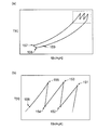
- FIG. 7 is a TS diagram of the Brayton cycle adopted by the refrigeration system 100 ′, in which the vertical axis indicates the temperature T [K] and the horizontal axis indicates the entropy S [KJ / kgK].
- FIG. 7B is an enlarged view of the area surrounded by the broken line in FIG.
- the refrigeration system 100 ′ expands the refrigerant 102 after the cooling, the compressor 102 that compresses the refrigerant, the heat exchanger 103 that cools the compressed refrigerant by exchanging heat with the cooling water, on the circulation path 101 through which the refrigerant flows.
- An expansion turbine 104, a cooling unit 105 including a heat exchanger for exchanging heat between the refrigerant and an object to be cooled, and a cold heat recovery heat exchanger 106 for recovering the cold heat of the refrigerant are sequentially provided.
- a counter-current heat exchanger type Brayton cycle is formed by the refrigeration cycle.
- the refrigeration system 100 ′ is intended for cooling a superconducting device (not shown) that uses a superconductor in a cryogenic state.
- a superconducting device (not shown) that uses a superconductor in a cryogenic state.
- liquid nitrogen is circulated as a refrigerant therein
- FIG. 6 shows only a circulation path 150 through which the liquid nitrogen circulates.
- the circulation path 150 is configured to exchange heat with the refrigerant flowing in the circulation path 101 of the refrigeration system 100 ′ in the cooling unit 105. Thereby, the liquid nitrogen flowing through the circulation path 150 heated by the heat load of the superconducting device is cooled by exchanging heat with the refrigerant flowing through the circulation path 101 cooled by the refrigeration system 100 ′.
- neon or the like is used as the refrigerant in the circulation path 101 of the refrigeration system 100 ′, but the present invention is not limited to this, and it goes without saying that the type of gas can be changed as appropriate according to the cooling temperature or the like. Yes.
- the refrigeration system 100 ′ includes a plurality of compressors 102a, 102b, 102c and heat exchangers 103a, 103b, 103c on a circulation path 101.
- the heat exchangers 103a, 103b, and 103c are provided on the downstream side of the compressors 102a, 102b, and 102c, respectively, and can cool the refrigerant that has been heated by adiabatic compression by exchanging heat with cooling water. Yes.
- the refrigerant flowing in the circulation path 101 is first adiabatically compressed by the compressor 102a on the most upstream side and the temperature rises (corresponding to reference numeral 151 in FIG. 7B), and then in the heat exchanger 103a provided on the downstream side. Cooling is performed by exchanging heat with cooling water (corresponding to reference numeral 152 in FIG. 7B). Then, after the refrigerant is adiabatically compressed again by the compressor 102b and the temperature rises (corresponding to reference numeral 153 in FIG. 7B), the refrigerant is cooled by exchanging heat with cooling water in the heat exchanger 103b provided on the downstream side. (Corresponding to reference numeral 154 in FIG. 7B).
- the refrigerant is adiabatically compressed again by the compressor 102c and the temperature rises (corresponding to reference numeral 155 in FIG. 7b), the refrigerant is cooled by exchanging heat with cooling water in the heat exchanger 103c provided on the downstream side. (Corresponding to reference numeral 156 in FIG. 7B).
- efficiency is improved by repeating adiabatic compression by the compressor 102 and cooling by the heat exchanger 103 over a plurality of stages. That is, by repeating adiabatic compression and cooling over a plurality of stages, the Brayton cycle compression process is brought close to ideal isothermal compression.
- the temperature of the refrigerant that has passed through the heat exchanger 103c is further cooled by the cold heat recovery heat exchanger 106 (corresponding to the reference numeral 157 in FIG. 7A), and then adiabatically expanded by the expansion turbine 104 to generate cold ( (Corresponding to reference numeral 158 in FIG. 7A).
- the expansion turbine 104 corresponds to the reference numeral 158 in FIG. 7A.
- FIG. 6 a refrigeration system 100 ′ having a single expansion turbine 104 is shown. However, similarly to the compressor 102, a plurality of expansion turbines may be provided in series with the circulation path 101. Good.
- the refrigerant discharged from the expansion turbine 104 is heat-exchanged with the liquid nitrogen flowing through the circulation path 150 in the superconducting device to be cooled in the cooling unit 105, and the temperature rises due to the heat load (reference numeral in FIG. 7A). 159).
- the refrigerant whose temperature has been raised in the cooling unit 105 is introduced into the cold heat recovery heat exchanger 106, and the remaining cold heat is recovered by exchanging heat with the high-temperature compressed refrigerant that has passed through the heat exchanger 103c.
- transduced into the expansion turbine 104 can be reduced using the cold heat which has remained in the refrigerant
- a Brayton cycle is configured using a plurality of rotating machines such as the compressor 102 and the expansion turbine 104.
- the upstream two compressors 102a and 102b are connected to both ends of the output shaft 108a of the electric motor 107a which is a common power source, respectively, thereby constituting the first unit 109a, thereby reducing the number of parts. It can be installed in a small installation space.
- the downstream compressor 102c and the expansion turbine 104 are also connected to both ends of the output shaft 108b of the electric motor 107b, which is a common power source, to constitute the second unit 109b, thereby reducing the number of parts.
- the power generated by the expansion turbine 104 contributes to the compression power of the compressor 102c, so that the efficiency is improved.
- compressor 102 or the expansion turbine 104 connected on the output shaft 108 of the common electric motor may be unitized by being placed on a gantry (not shown).
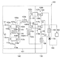
- FIG. 1 is a schematic diagram illustrating an overall configuration of a refrigeration system 100 according to the present embodiment.
- a superconducting device is shown as a cooling target 160
- a pump 170 for circulating liquid nitrogen is shown on a circulation path 150 for cooling the cooling target 160.
- the refrigeration system 100 can perform cooling based on basically the same Brayton cycle as the refrigeration system 100 ′ described above, but at least one of the rotating machines such as the compressor 102 or the expansion turbine 104 is provided in the circulation path 101. On the other hand, it is different in that a plurality are provided in parallel.
- the compressors 112a and 112b are provided at both ends of the output shaft 118a of the common motor 117a.
- a backup unit 119 a is provided in parallel to the circulation path 101.
- the first unit 109a and the backup unit 119a can be selected by switching the switching valves V1 and V2, and the backup unit 119a is selected when an abnormality occurs in the first unit 109a used in normal operation. To be operated.
- the heat exchanger 103a is shared between the first unit 109a and the backup unit 119a. This is because the heat exchanger 103a is not a rotating machine such as the compressors 102a and 102b, so the risk of occurrence of abnormality is low, and space is saved by sharing between the units.
- the heat exchanger 103a is provided with switching valves V3 and V4 on the downstream side between the first unit 109a and the backup unit 119a, respectively, and can be switched according to the unit used. .
- a backup in which the compressors 112c and 114 are provided at both ends of the output shaft 118b of the common electric motor 117b.
- the unit 119b is provided in parallel to the circulation path 101.
- the second unit 109b and the backup unit 119b can be selected by switching the switching valves V5 and V6, and the backup unit 119b is selected when an abnormality occurs in the second unit 109b used in the normal state. To be operated.
- the heat exchanger 103b is shared between the second unit 109b and the backup unit 119b. This is because the heat exchanger 103b is not a rotating machine such as the compressor 102c or the expansion turbine 104, and therefore has a low risk of abnormality, and is shared between units to save space.
- the heat exchanger 103c and the cold heat recovery heat exchanger 106 are provided with a switching valve V7 and a valve 8 between the second unit 109b and the backup unit 119b, respectively, on the downstream side thereof, depending on the unit used. Can be switched.
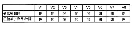
- FIG. 2 shows an operation example of the switching valves V1 to V8 in the refrigeration system 100 shown in FIG.
- the upper part of FIG. 2 shows the state of the switching valves V1 to V8 when the refrigeration system 100 is operating normally (during normal operation).
- the refrigerant is guided to the first unit 109a side by opening the switching valve V1, and the refrigerant to the backup unit 119a side is blocked by closing V2.
- the switching valve V3 and closing the switching valve V4 the refrigerant compressed by the compressor 102a is guided to the downstream compressor 102b through the heat exchanger 103a.
- the refrigerant is guided to the second unit 109b side by opening the switching valve V5, and the refrigerant to the backup unit 119b side is blocked by closing V6.
- the switching valve V7 and closing the switching valve V8 the refrigerant compressed by the compressor 102c is guided to the downstream expansion turbine 104 via the heat exchanger 103c and the cold recovery heat exchanger 106. .
- FIG. 2 shows the state of the switching valves V1 to V8 when an abnormality has occurred in the compressor 102a or 102b constituting the first unit 109a used during normal operation of the refrigeration system 100.
- the refrigerant to the first unit 109a side where an abnormality has occurred is shut off by closing the switching valve V1, and the refrigerant is introduced to the backup unit 119a side by opening V2.
- the switching valve V3 and opening the switching valve V4 the refrigerant compressed by the compressor 112a is guided to the downstream compressor 112b through the heat exchanger 103a.
- the open / close states of the switching valves V5 to V8 are not different from the upper stage.
- the switching valves V5 to V8 are operated by the same concept (specifically, to the second unit 109b). Then, the switching valve V5 is closed and the switching valve V6 is opened to introduce the refrigerant to the backup unit 119b side, and the switching valve V7 is closed and the switching valve V8 is opened.
- the refrigerant that has passed through the compressor 112c is guided to the expansion turbine 114 through the heat exchanger 103c and the cold recovery heat exchanger 106).
- switching the switching valves V1 to V8 By switching the switching valves V1 to V8 in this way, the backup unit can be driven and the operation of the refrigeration system 100 can be continued even when an abnormality occurs in the main unit.
- Such switching operation of the switching valves V1 to V8 may be performed manually when the operator finds an abnormality, or the abnormality can be corrected by incorporating a control program into a controller composed of a microprocessor or the like. Switching may be automatically controlled when it is detected.
- expansion turbines 104 and 114, a cooling unit 105, and a cold recovery heat exchanger 106 that are arranged on the cooling target side and through which relatively low-temperature cold heat flows are connected to the outside. It is housed as a unit in a cold box 130 that can be insulated.
- the cold box 130 has, for example, a vacuum heat insulating layer between the inner and outer surfaces to prevent heat from entering from the outside, and the relatively low temperature expansion turbines 104 and 114, the heat exchanger 105, and the cold recovery heat exchanger 106. Prevent heat loss from.
- the compressors 102a, 102b, and 102c and the heat exchangers 103a, 103b, and 103c are integrated together as a compressor unit 140 outside the cold box 130 because a relatively high-temperature refrigerant flows.
- the cold box 130 is disposed closer to the object to be cooled than the compressor unit 140. Thereby, the cold heat generated in the cold box 130 can be supplied to the object to be cooled with a small loss, and good refrigeration efficiency can be achieved.
- the compressor unit 140 since the compressor unit 140 is configured as a separate body from the cold box 130, the compressor unit 140 can be dispersed and arranged at positions away from the cold box 130. As a result, even when there is little laying space around the object to be cooled, only the cold box 130 is arranged in the vicinity of the object to be cooled, and the compressor unit 140 is distributed in a distant space so that a narrow laying space is obtained. Also, the refrigeration apparatus 100 can be introduced.
- the refrigeration system 100 by providing a plurality of rotating machines responsible for the compression process and the expansion process in the refrigeration cycle in parallel with the circulation path 101 through which the refrigerant flows, Even if an abnormality (for example, a failure) occurs in one of the rotating machines, the other rotating machine can be made to function as a backup, so that the operation can be continued.
- rotating machines tend to be at a higher risk of anomalies than other components, so by providing backups only for rotating machines with a higher risk of anomalies, the overall system size can be increased. The reliability can be improved while suppressing.
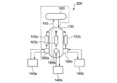
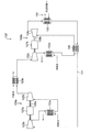
- FIG. 3 is a schematic diagram showing the overall configuration of the refrigeration system 200 according to the first modification.
- the same reference numerals are assigned to portions common to the above-described embodiment, and overlapping descriptions are omitted as appropriate.
- the refrigeration system 200 according to the first modification is common to the above-described embodiment in that the refrigeration system 200 includes a cold box 130 and a compressor unit 140, but three compressions are performed for one cold box 130. The difference is that machine units 140a, 140b, 140c are provided. Each compressor unit 140 is connected to the cold box 130 via a pipe for circulating the refrigerant.
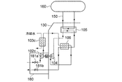
- FIG. 4 is a diagram showing details of a region surrounded by a broken line in FIG. In FIG. 4, one of the three systems provided corresponding to the three compressor units shown in FIG. 3 is representatively shown, and the other two systems have the same configuration.
- a box 180 is provided between each compressor unit 140 and the cold box 130.
- Each box 180 includes switching valves 181a and 181b for switching the communication state of the refrigerant inlet / outlet line between the compressor unit 140 and the cold box 130, the compressor 102c of the second compressor unit 109b, and the electric motor 107b.
- Compressor connection piping is arranged.
- the box 180 is supplied with the refrigerant compressed by the compressors 102a and 102b in the compressor unit 140, and is further compressed by the compression unit 102c to be sent to the heat exchanger 103c via the compressed gas connection line.
- the switching valves 181a and 181b may also serve as V5 and V1.
- the refrigeration system 200 When the refrigeration system 200 is operating normally, the refrigeration system 200 is operated by selectively driving any one of the three compressor units 140. The selected compression When an abnormality occurs in the compressor unit 140, the switching valves 181a and 181b in each box 180 are operated to switch to the other two compressor units 140 and the operation of the refrigeration system 200 is continued. .
- a plurality of the three compressor units 140 may be simultaneously operated in parallel. In this case, since the load per one compressor unit 140 is reduced, the efficiency of the system can be improved. However, since the backup compressor unit 140 is substantially reduced by that amount, compression is performed from the balance. The number of operations of the machine unit 140 may be determined.
- each compressor unit 140 can be arranged away from the cold box 130 that must be arranged near the object to be cooled, it is a case where a wide installation space necessary for the entire refrigeration system cannot be secured around the object to be cooled.
- the refrigeration system 200 that can be arranged in a small installation space can be realized.
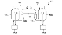
- FIG. 5 is a schematic diagram illustrating an overall configuration of a refrigeration system 300 according to a second modification. Note that in FIG. 5, the same reference numerals are given to portions common to the above-described embodiment, and redundant description will be omitted as appropriate.
- the refrigeration system 300 according to the second modification is common to the above-described embodiment in that the refrigeration system 300 includes a cold box 130 and a compressor unit 140, but includes two cold boxes 130a and 130b. The difference is that one compressor unit 140a, 140b is provided for each cold box 130. That is, one cold box 130 and one compressor unit 140 are set as a set and provided with a backup.
- the set of the cold box 130a and the compressor unit 140a is operated during normal operation of the refrigeration system 300, and the set of the cold box 130b and the compressor unit 140b is operated when a failure occurs. By switching, continuous operation is possible.
- the present invention includes a compressor that compresses a refrigerant on a circulation path through which the refrigerant flows, a heat exchanger that cools the compressed refrigerant, an expansion turbine that expands the cooled refrigerant to generate cold, and
- the present invention can be used in a refrigeration system having a refrigeration cycle in which a cooling unit that cools an object to be cooled by cold heat is sequentially provided.
Landscapes
- Engineering & Computer Science (AREA)
- Physics & Mathematics (AREA)
- Mechanical Engineering (AREA)
- Thermal Sciences (AREA)
- General Engineering & Computer Science (AREA)
- Devices That Are Associated With Refrigeration Equipment (AREA)
- Structures Of Non-Positive Displacement Pumps (AREA)
Priority Applications (6)
| Application Number | Priority Date | Filing Date | Title |
|---|---|---|---|
| ES14791203T ES2751347T3 (es) | 2013-05-02 | 2014-03-20 | Sistema de refrigeración |
| KR1020157033129A KR101762056B1 (ko) | 2013-05-02 | 2014-03-20 | 냉동 시스템 |
| CN201480024722.9A CN105209836B (zh) | 2013-05-02 | 2014-03-20 | 冷冻系统 |
| RU2015151396A RU2627996C2 (ru) | 2013-05-02 | 2014-03-20 | Система охлаждения |
| EP14791203.4A EP2975337B1 (en) | 2013-05-02 | 2014-03-20 | Refrigerating system |
| US14/888,235 US10168078B2 (en) | 2013-05-02 | 2014-03-20 | Refrigeration system |
Applications Claiming Priority (2)
| Application Number | Priority Date | Filing Date | Title |
|---|---|---|---|
| JP2013-097143 | 2013-05-02 | ||
| JP2013097143A JP5782065B2 (ja) | 2013-05-02 | 2013-05-02 | 冷凍システム |
Publications (1)
| Publication Number | Publication Date |
|---|---|
| WO2014178240A1 true WO2014178240A1 (ja) | 2014-11-06 |
Family
ID=51843375
Family Applications (1)
| Application Number | Title | Priority Date | Filing Date |
|---|---|---|---|
| PCT/JP2014/057678 WO2014178240A1 (ja) | 2013-05-02 | 2014-03-20 | 冷凍システム |
Country Status (8)
| Country | Link |
|---|---|
| US (1) | US10168078B2 (ko) |
| EP (1) | EP2975337B1 (ko) |
| JP (1) | JP5782065B2 (ko) |
| KR (1) | KR101762056B1 (ko) |
| CN (1) | CN105209836B (ko) |
| ES (1) | ES2751347T3 (ko) |
| RU (1) | RU2627996C2 (ko) |
| WO (1) | WO2014178240A1 (ko) |
Cited By (3)
| Publication number | Priority date | Publication date | Assignee | Title |
|---|---|---|---|---|
| US20170233083A1 (en) * | 2016-02-16 | 2017-08-17 | The Boeing Company | Thermal management systems and methods |
| CN107429954A (zh) * | 2015-05-01 | 2017-12-01 | 株式会社前川制作所 | 冷冻机以及冷冻机的运转方法 |
| US9970449B2 (en) | 2013-11-11 | 2018-05-15 | Mayekawa Mfg. Co., Ltd. | Expander-integrated compressor, refrigerator and operating method for refrigerator |
Families Citing this family (17)
| Publication number | Priority date | Publication date | Assignee | Title |
|---|---|---|---|---|
| KR101722608B1 (ko) * | 2015-06-15 | 2017-04-03 | 대우조선해양 주식회사 | 증발가스 처리 시스템 및 방법 |
| KR101722606B1 (ko) * | 2015-06-15 | 2017-04-03 | 대우조선해양 주식회사 | 증발가스 처리 시스템 및 방법 |
| KR101722603B1 (ko) * | 2015-06-15 | 2017-04-03 | 대우조선해양 주식회사 | 증발가스 처리 시스템 및 방법 |
| KR101722604B1 (ko) * | 2015-06-15 | 2017-04-03 | 대우조선해양 주식회사 | 증발가스 처리 시스템 및 방법 |
| KR101722607B1 (ko) * | 2015-06-15 | 2017-04-03 | 대우조선해양 주식회사 | 증발가스 처리 시스템 및 방법 |
| KR101722605B1 (ko) * | 2015-06-15 | 2017-04-03 | 대우조선해양 주식회사 | 증발가스 처리 시스템 및 방법 |
| KR101670882B1 (ko) * | 2015-06-15 | 2016-10-31 | 대우조선해양 주식회사 | 증발가스 처리 시스템 및 방법 |
| KR101670883B1 (ko) * | 2015-06-15 | 2016-10-31 | 대우조선해양 주식회사 | 증발가스 처리 시스템 및 방법 |
| JP6650754B2 (ja) * | 2015-12-25 | 2020-02-19 | 株式会社前川製作所 | 膨張機一体型圧縮機及び冷凍機 |
| CN107560208B (zh) * | 2016-06-30 | 2020-08-04 | 新特能源股份有限公司 | 一种氟利昂制冷系统 |
| WO2018132785A1 (en) | 2017-01-16 | 2018-07-19 | Praxair Technology, Inc. | Refrigeration cycle for liquid oxygen densification |
| JP2020007986A (ja) * | 2018-07-10 | 2020-01-16 | 住友重機械工業株式会社 | クライオポンプシステム |
| CN110375450A (zh) * | 2019-07-03 | 2019-10-25 | 天津大学 | 一种二氧化碳制冷热泵系统 |
| FR3099820B1 (fr) * | 2019-08-05 | 2022-11-04 | Air Liquide | Dispositif et installation de réfrigération |
| FR3099815B1 (fr) * | 2019-08-05 | 2021-09-10 | Air Liquide | Dispositif et installation de réfrigération |
| WO2022062272A1 (zh) * | 2020-09-27 | 2022-03-31 | 李华玉 | 回热式热力循环与新型回热机械压缩式热泵 |
| JP2022087607A (ja) * | 2020-12-01 | 2022-06-13 | 株式会社前川製作所 | 冷凍システム |
Citations (5)
| Publication number | Priority date | Publication date | Assignee | Title |
|---|---|---|---|---|
| JPH02143057A (ja) * | 1988-11-24 | 1990-06-01 | Hitachi Ltd | 極低温寒冷発生装置 |
| JPH05272357A (ja) * | 1992-03-27 | 1993-10-19 | Nippon Sanso Kk | 圧縮機及びその運転方法 |
| JPH09329034A (ja) | 1996-06-11 | 1997-12-22 | Ishikawajima Harima Heavy Ind Co Ltd | 閉サイクルガスタービン |
| JP2003148824A (ja) | 2001-11-13 | 2003-05-21 | Daikin Ind Ltd | 空気調和装置 |
| JP2009210138A (ja) * | 2008-02-29 | 2009-09-17 | Mitsubishi Heavy Ind Ltd | 冷凍サイクルシステム |
Family Cites Families (17)
| Publication number | Priority date | Publication date | Assignee | Title |
|---|---|---|---|---|
| US2737031A (en) * | 1952-02-12 | 1956-03-06 | William A Wulle | Heat energy-converting system and process |
| US3677019A (en) | 1969-08-01 | 1972-07-18 | Union Carbide Corp | Gas liquefaction process and apparatus |
| US3668884A (en) | 1970-05-05 | 1972-06-13 | William H Nebgen | Refrigeration system, heat recovery system, refrigerated gas compression system and brayton cycle system |
| JPS58217163A (ja) * | 1982-06-10 | 1983-12-17 | 株式会社前川製作所 | 圧縮式冷凍サイクルの冷凍能力増加装置 |
| JPS60207888A (ja) * | 1984-03-31 | 1985-10-19 | 株式会社東芝 | ヘリウム液化装置 |
| JPH0652145B2 (ja) * | 1987-12-12 | 1994-07-06 | 中島 茂 | 超低温冷凍装置 |
| JPH0784961B2 (ja) * | 1990-07-23 | 1995-09-13 | 株式会社日立製作所 | ヘリウム液化冷凍機 |
| JPH06101919A (ja) * | 1992-09-18 | 1994-04-12 | Hitachi Ltd | 極低温冷凍装置 |
| AUPM485694A0 (en) | 1994-04-05 | 1994-04-28 | Bhp Petroleum Pty. Ltd. | Liquefaction process |
| US6112550A (en) * | 1998-12-30 | 2000-09-05 | Praxair Technology, Inc. | Cryogenic rectification system and hybrid refrigeration generation |
| JP4457928B2 (ja) | 2005-03-15 | 2010-04-28 | ダイキン工業株式会社 | 冷凍装置 |
| JP4241699B2 (ja) * | 2005-09-12 | 2009-03-18 | 三菱重工業株式会社 | 空気冷媒冷凍システム、空気冷媒冷凍システムによるバックアップ方法 |
| US8020406B2 (en) * | 2007-11-05 | 2011-09-20 | David Vandor | Method and system for the small-scale production of liquified natural gas (LNG) from low-pressure gas |
| JP4644278B2 (ja) | 2008-10-03 | 2011-03-02 | パナソニック株式会社 | 冷凍サイクル装置 |
| WO2010113158A1 (en) * | 2009-04-01 | 2010-10-07 | Linum Systems, Ltd. | Waste heat air conditioning system |
| UA97163C2 (ru) * | 2010-03-01 | 2012-01-10 | Восточноукраинский Национальный Университет Имени Владимира Даля | Воздушная холодильная машина крайнюка |
| AU2012324797C1 (en) | 2011-10-21 | 2018-08-16 | Single Buoy Moorings Inc. | Multi nitrogen expansion process for LNG production |
-
2013
- 2013-05-02 JP JP2013097143A patent/JP5782065B2/ja active Active
-
2014
- 2014-03-20 WO PCT/JP2014/057678 patent/WO2014178240A1/ja active Application Filing
- 2014-03-20 RU RU2015151396A patent/RU2627996C2/ru active
- 2014-03-20 ES ES14791203T patent/ES2751347T3/es active Active
- 2014-03-20 US US14/888,235 patent/US10168078B2/en active Active
- 2014-03-20 EP EP14791203.4A patent/EP2975337B1/en active Active
- 2014-03-20 KR KR1020157033129A patent/KR101762056B1/ko active IP Right Grant
- 2014-03-20 CN CN201480024722.9A patent/CN105209836B/zh active Active
Patent Citations (5)
| Publication number | Priority date | Publication date | Assignee | Title |
|---|---|---|---|---|
| JPH02143057A (ja) * | 1988-11-24 | 1990-06-01 | Hitachi Ltd | 極低温寒冷発生装置 |
| JPH05272357A (ja) * | 1992-03-27 | 1993-10-19 | Nippon Sanso Kk | 圧縮機及びその運転方法 |
| JPH09329034A (ja) | 1996-06-11 | 1997-12-22 | Ishikawajima Harima Heavy Ind Co Ltd | 閉サイクルガスタービン |
| JP2003148824A (ja) | 2001-11-13 | 2003-05-21 | Daikin Ind Ltd | 空気調和装置 |
| JP2009210138A (ja) * | 2008-02-29 | 2009-09-17 | Mitsubishi Heavy Ind Ltd | 冷凍サイクルシステム |
Cited By (7)
| Publication number | Priority date | Publication date | Assignee | Title |
|---|---|---|---|---|
| US9970449B2 (en) | 2013-11-11 | 2018-05-15 | Mayekawa Mfg. Co., Ltd. | Expander-integrated compressor, refrigerator and operating method for refrigerator |
| CN107429954A (zh) * | 2015-05-01 | 2017-12-01 | 株式会社前川制作所 | 冷冻机以及冷冻机的运转方法 |
| EP3249319A4 (en) * | 2015-05-01 | 2018-02-21 | Mayekawa Mfg. Co., Ltd. | Refrigerator and operation method for refrigerator |
| US10415857B2 (en) | 2015-05-01 | 2019-09-17 | Mayekawa Mfg. Co., Ltd. | Refrigerator and operation method for refrigerator |
| CN107429954B (zh) * | 2015-05-01 | 2020-05-26 | 株式会社前川制作所 | 冷冻机以及冷冻机的运转方法 |
| US20170233083A1 (en) * | 2016-02-16 | 2017-08-17 | The Boeing Company | Thermal management systems and methods |
| US10017032B2 (en) * | 2016-02-16 | 2018-07-10 | The Boeing Company | Thermal management systems and methods |
Also Published As
| Publication number | Publication date |
|---|---|
| RU2627996C2 (ru) | 2017-08-14 |
| KR101762056B1 (ko) | 2017-07-26 |
| RU2015151396A (ru) | 2017-06-07 |
| CN105209836A (zh) | 2015-12-30 |
| EP2975337A4 (en) | 2016-12-21 |
| KR20160002990A (ko) | 2016-01-08 |
| US20160076793A1 (en) | 2016-03-17 |
| EP2975337B1 (en) | 2019-09-18 |
| US10168078B2 (en) | 2019-01-01 |
| EP2975337A1 (en) | 2016-01-20 |
| ES2751347T3 (es) | 2020-03-31 |
| JP5782065B2 (ja) | 2015-09-24 |
| JP2014219125A (ja) | 2014-11-20 |
| CN105209836B (zh) | 2017-08-04 |
Similar Documents
| Publication | Publication Date | Title |
|---|---|---|
| JP5782065B2 (ja) | 冷凍システム | |
| KR101735623B1 (ko) | 브레이턴 사이클 냉동기 | |
| US11022349B2 (en) | Hydronic system for combining free cooling and mechanical cooling | |
| KR101859231B1 (ko) | 냉장 냉동 복합 시스템 | |
| CN108474371B (zh) | 双氦气压缩机 | |
| JP2014206330A (ja) | チラー装置 | |
| EP3465029A1 (en) | Air and water cooled chiller for free cooling applications | |
| JP5380310B2 (ja) | 極低温冷凍機 | |
| JP2010169309A (ja) | 空気調和機 | |
| JP3995825B2 (ja) | 空調機 | |
| JP2019095079A (ja) | 高温超電導電力機器用冷却システム及びその運転方法 | |
| WO2023135958A1 (ja) | 冷凍装置 | |
| JP2011257036A (ja) | 温度調整装置 | |
| WO2018003099A1 (ja) | 冷却装置 | |
| WO2018216112A1 (ja) | 冷凍サイクル装置 | |
| JP2021127885A (ja) | 極低温システム | |
| JP2022087916A (ja) | 熱源設備 | |
| JP5315102B2 (ja) | 冷凍機及び冷凍空調システム | |
| JP2011202862A (ja) | 冷凍装置 | |
| JP2017211129A (ja) | 空調システム | |
| JP2017116122A (ja) | 熱交換装置 |
Legal Events
| Date | Code | Title | Description |
|---|---|---|---|
| 121 | Ep: the epo has been informed by wipo that ep was designated in this application |
Ref document number: 14791203 Country of ref document: EP Kind code of ref document: A1 |
|
| WWE | Wipo information: entry into national phase |
Ref document number: 2014791203 Country of ref document: EP |
|
| WWE | Wipo information: entry into national phase |
Ref document number: 14888235 Country of ref document: US |
|
| NENP | Non-entry into the national phase |
Ref country code: DE |
|
| ENP | Entry into the national phase |
Ref document number: 20157033129 Country of ref document: KR Kind code of ref document: A |
|
| ENP | Entry into the national phase |
Ref document number: 2015151396 Country of ref document: RU Kind code of ref document: A |