WO2014167810A1 - 危険車両通知装置、危険車両通知プログラム製品、危険車両通知方法 - Google Patents
危険車両通知装置、危険車両通知プログラム製品、危険車両通知方法 Download PDFInfo
- Publication number
- WO2014167810A1 WO2014167810A1 PCT/JP2014/001951 JP2014001951W WO2014167810A1 WO 2014167810 A1 WO2014167810 A1 WO 2014167810A1 JP 2014001951 W JP2014001951 W JP 2014001951W WO 2014167810 A1 WO2014167810 A1 WO 2014167810A1
- Authority
- WO
- WIPO (PCT)
- Prior art keywords
- vehicle
- dangerous
- determination
- unit
- target
- Prior art date
- Legal status (The legal status is an assumption and is not a legal conclusion. Google has not performed a legal analysis and makes no representation as to the accuracy of the status listed.)
- Ceased
Links
Images


Classifications
-
- G—PHYSICS
- G08—SIGNALLING
- G08G—TRAFFIC CONTROL SYSTEMS
- G08G1/00—Traffic control systems for road vehicles
- G08G1/123—Traffic control systems for road vehicles indicating the position of vehicles, e.g. scheduled vehicles; Managing passenger vehicles circulating according to a fixed timetable, e.g. buses, trains, trams
- G08G1/133—Traffic control systems for road vehicles indicating the position of vehicles, e.g. scheduled vehicles; Managing passenger vehicles circulating according to a fixed timetable, e.g. buses, trains, trams within the vehicle ; Indicators inside the vehicles or at stops
- G08G1/137—Traffic control systems for road vehicles indicating the position of vehicles, e.g. scheduled vehicles; Managing passenger vehicles circulating according to a fixed timetable, e.g. buses, trains, trams within the vehicle ; Indicators inside the vehicles or at stops the indicator being in the form of a map
-
- G—PHYSICS
- G08—SIGNALLING
- G08G—TRAFFIC CONTROL SYSTEMS
- G08G1/00—Traffic control systems for road vehicles
- G08G1/16—Anti-collision systems
- G08G1/161—Decentralised systems, e.g. inter-vehicle communication
- G08G1/162—Decentralised systems, e.g. inter-vehicle communication event-triggered
-
- G—PHYSICS
- G09—EDUCATION; CRYPTOGRAPHY; DISPLAY; ADVERTISING; SEALS
- G09B—EDUCATIONAL OR DEMONSTRATION APPLIANCES; APPLIANCES FOR TEACHING, OR COMMUNICATING WITH, THE BLIND, DEAF OR MUTE; MODELS; PLANETARIA; GLOBES; MAPS; DIAGRAMS
- G09B29/00—Maps; Plans; Charts; Diagrams, e.g. route diagram
- G09B29/003—Maps
- G09B29/006—Representation of non-cartographic information on maps, e.g. population distribution, wind direction, radiation levels, air and sea routes
-
- G—PHYSICS
- G09—EDUCATION; CRYPTOGRAPHY; DISPLAY; ADVERTISING; SEALS
- G09B—EDUCATIONAL OR DEMONSTRATION APPLIANCES; APPLIANCES FOR TEACHING, OR COMMUNICATING WITH, THE BLIND, DEAF OR MUTE; MODELS; PLANETARIA; GLOBES; MAPS; DIAGRAMS
- G09B29/00—Maps; Plans; Charts; Diagrams, e.g. route diagram
- G09B29/10—Map spot or coordinate position indicators; Map reading aids
Definitions
- This disclosure relates to a technique for notifying a driver of other dangerous vehicles existing around a vehicle using inter-vehicle communication.
- Patent Document 1 a technique for displaying the position and traveling direction of a vehicle (that is, a surrounding vehicle) existing around a vehicle, acquired by using inter-vehicle communication, superimposed on a map image. There is.
- An object of the present disclosure is to provide a dangerous vehicle notification device, a dangerous vehicle notification program product, and a dangerous vehicle notification method capable of notifying a driver of a vehicle whether or not a surrounding vehicle is driving dangerously. It is in.
- the dangerous vehicle notification device is provided as follows.
- the dangerous vehicle notification device is mounted on a vehicle and transmits / receives data via wireless communication to / from another dangerous vehicle notification device that is mounted on each of a plurality of other vehicles different from the vehicle and has the same function.
- the dangerous vehicle notification device transmits a position detection unit that detects the position of the vehicle, position data indicating the position of the vehicle, and a position indicating the position of each other vehicle transmitted by each other vehicle.
- an in-vehicle communication device for receiving data.
- the dangerous vehicle notification device is (i) a mark display processing unit that displays on the display a mark indicating the position of each other vehicle based on the position data of each other vehicle received by the in-vehicle communication device, (ii) A determination information acquisition unit for acquiring determination information used to determine whether or not the vehicle is driving dangerously; (iii) the determination information acquired by the determination information acquisition unit; A transmission control unit that transmits via an in-vehicle communication device, (iv) the information for determination used to determine whether or not each other vehicle transmits a dangerous driving for each other vehicle, A reception control unit that receives via an in-vehicle communication device; (v) a dangerous vehicle determination that determines whether or not each other vehicle is driving dangerously from the determination information of each other vehicle received by the reception control unit; A part.
- the dangerous vehicle notification device determines that the mark indicating the position of the target other vehicle that is the other vehicle determined to be dangerously driven by the dangerous vehicle determination unit is dangerously driven.
- a dangerous vehicle display processing unit for displaying in a first display mode different from the second display mode for displaying the mark indicating the position of each other vehicle that has not been provided.
- the dangerous vehicle determination unit of the dangerous vehicle notification device mounted on the vehicle is a vehicle in which the other vehicle is performing dangerous driving based on the determination information of the other vehicle transmitted by the other vehicle. It is determined whether or not. Then, the target other vehicle determined to be a vehicle that is driving dangerously is displayed on the display in a display mode (also referred to as a display format) that is different from that of the other vehicle that is determined not to perform other dangerous driving.
- the driver of the vehicle can recognize whether or not the other vehicle traveling around the vehicle is a dangerous driving vehicle by looking at the display. Therefore, according to the above configuration, it is possible to notify the driver of the vehicle whether or not the surrounding vehicle is driving dangerously.
- the dangerous vehicle notification program product is provided as follows. That is, the computer is included in the dangerous vehicle notification device of the first example, the determination information acquisition unit, the transmission control unit, the reception control unit, the mark display processing unit, the dangerous vehicle determination unit, And a dangerous vehicle notification program product recorded in a computer-readable non-transition storage medium, including instructions for functioning as the dangerous vehicle display processing unit.
- the dangerous vehicle notification program product is provided as follows. That is, the determination information acquisition unit, the transmission control unit, the reception control unit, the mark display processing unit, and the dangerous vehicle determination, which are executed by a computer and included in the dangerous vehicle notification device of the first example. And a dangerous vehicle notification method for realizing the function as the dangerous vehicle display processing unit.
- FIG. 1 is a diagram illustrating an example of a schematic configuration of a vehicle-to-vehicle communication system (hereinafter, referred to as a dangerous vehicle notification system) 100 to which a dangerous vehicle notification device 1 according to the present disclosure is applied.
- the dangerous vehicle notification system 100 includes a dangerous vehicle notification device 1 that is used one by one for each of a plurality of vehicles.
- the plurality of vehicles include a vehicle A and a plurality of vehicles B that are not shown in FIG.
- Vehicle A is referred to as a main vehicle or simply a vehicle, and vehicle B is also referred to as another vehicle.
- the relationship between these main vehicles and other vehicles is relatively determined. If one vehicle B is the main vehicle, the vehicle A naturally becomes another vehicle for the vehicle B.
- the host vehicle for the certain apparatus it is also referred to as the host vehicle for the certain apparatus.
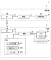
- FIG. 2 is a diagram illustrating an example of a schematic configuration of the dangerous vehicle notification device 1.
- the dangerous vehicle notification device 1 includes a mobile terminal 2 and a communication device 3.
- the mobile terminal 2 obtains data to be transmitted to other vehicles (hereinafter simply referred to as surrounding vehicles) existing around the main vehicle where the mobile terminal 2 is mounted, and displays the data received from the surrounding vehicles on the display 27. It is a device for notifying the driver of the main vehicle via.
- the periphery of the main vehicle means a range in which the communication device 3 described later can perform wireless communication.
- the mobile terminal 2 may be configured to use a known multifunction mobile phone such as a smartphone. As an example, the mobile terminal 2 is temporarily fixed in the passenger compartment so that the driver of the main vehicle can visually recognize the display 27 of the mobile terminal 2.
- the mounting orientation of the mobile terminal 2 with respect to the main vehicle (the orientation of the mobile terminal 2 with respect to the front-rear direction of the main vehicle, the angle of the own terminal with respect to the horizontal plane, etc.) is set in the mobile terminal 2 in advance.
- the display 27 is directed to the driver's seat at 110 degrees with respect to the horizontal plane, and the mapping component to the horizontal plane in the vertical direction of the mobile terminal 2 matches the front-rear direction of the main vehicle. Install.
- the mounting posture of the mobile terminal 2 on the vehicle is not limited to this, and may be set by a driver.
- the mobile terminal 2 includes a mobile side Bluetooth (registered trademark, hereinafter referred to as BT) communication unit 21, a detection unit 22, a memory 26, a display 27, and a mobile side control circuit 28 in order to realize the above-described device function. I have.
- BT mobile side Bluetooth
- the portable-side BT communication unit 21 includes a transmission / reception antenna and exchanges information with the communication device 3 of the main vehicle by performing communication according to the Bluetooth standard (hereinafter referred to as BT communication).
- BT communication the Bluetooth standard
- the configuration in which the communication between the mobile terminal 2 and the communication device 3 is performed by BT communication is shown, but the configuration is not necessarily limited thereto.
- it may be configured to perform wireless communication according to short-range wireless communication standards such as ZigBee (registered trademark) or wireless LAN standards such as IEEE 802.11, or may be configured to perform wired communication such as USB communication.
- the portable BT communication unit 21 is also referred to as a separate communication unit or an additional communication unit.
- the detection unit 22 acquires various data for generating information for determining whether or not the driving of the main vehicle is a safe driving.
- the detection unit 22 includes a GPS receiver 221 that receives radio waves from a GPS (Global Positioning System) satellite, an acceleration sensor 222 that detects acceleration acting on the terminal, an angular velocity acting on the terminal, A gyro sensor 223 for detecting an angle is provided.
- GPS Global Positioning System
- the memory 26 is electrically rewritable for storing the map data for route guidance and the program 4 for operating a portable terminal such as a known multi-function mobile phone as the portable terminal 2 according to the present embodiment. It is a non-volatile memory.
- the memory 26 may be a storage medium that is removable from the portable terminal 2 such as an SD card.
- the memory 26 is configured not to erase the stored data unless an instruction to erase is given by an operation by the driver.
- the program 4 for causing a known mobile terminal to operate as the mobile terminal 2 according to the present embodiment may be installed in a storage area such as a ROM provided in the mobile-side control circuit 28 described later. This program 4 is also referred to as a dangerous vehicle notification program product.
- the display 27 displays text and images based on signals input from the mobile control circuit 28.
- the display 27 is capable of full-color display and can be configured using a TFT liquid crystal display, an organic EL display, or the like.
- the portable-side control circuit 28 is configured as a normal computer, and has a well-known CPU, memory such as ROM, RAM, and EEPROM, I / O, and a bus line for connecting these configurations (all not shown). Etc.).
- the portable side control circuit 28 executes various processes by the CPU executing programs stored in advance in the ROM or the memory 26 based on various information input from the portable side BT communication unit 21 and the detection unit 22.
- the portable control circuit 28 may be realized as a hardware configuration as one or a plurality of ICs.
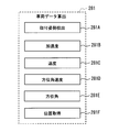
- the portable side control circuit 28 includes a vehicle data calculation unit 281, an internal memory 282, and a transmission control unit 283 as functional blocks for processing data to be transmitted to surrounding vehicles.
- a reception control unit 284 As a functional block for processing data received from surrounding vehicles, a reception control unit 284, a vehicle identification unit 285, a dangerous vehicle determination unit 286, a map image drawing unit 287, a surrounding vehicle display unit 288, and a risk determination continuation unit 289.
- the internal memory 282 is constructed in an electrically rewritable memory such as a RAM or an EEPROM.
- the vehicle data calculation unit 281 calculates various data (vehicle data) related to the traveling state of the main vehicle from various sensor data sequentially detected by the detection unit 22 and stores the data in the internal memory 282.
- the vehicle data calculated by the vehicle data calculation unit 281 includes, for example, the position of the mobile terminal 2 (that is, the position of the main vehicle), the traveling speed of the main vehicle, the acceleration acting on the main vehicle, and the traveling direction of the main vehicle. (Hereinafter referred to as azimuth angle) and azimuth velocity.
- azimuth angle azimuth angle
- azimuth velocity azimuth velocity
- the vehicle data may be only the position and acceleration of the main vehicle.
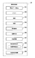
- the vehicle data calculation unit 281 includes, as shown in FIG. 4, an own terminal mounting posture detection unit 281A, an acceleration calculation unit 281B, a speed calculation unit 281C, and an azimuth angular velocity calculation unit 281D. , An azimuth angle calculation unit 281E, and a position acquisition unit 281F.
- the vehicle data calculation unit 281 can also be said to function as a determination information acquisition unit, while vehicle data is also referred to as determination information.
- the own terminal mounting posture detection unit 281A detects the mounting posture of the mobile terminal 2 with respect to the main vehicle.
- the mounting posture with respect to the main vehicle is set in advance as in the present embodiment, the set value is used, but the present invention is not limited to this.
- the portable terminal 2 provided with the acceleration sensor 222 and the gyro sensor 223, the direction of the own terminal and the inclination with respect to a horizontal surface can be detected from these sensor data by a known technique.
- the front-rear direction of the main vehicle may be detected from the time-series data of the position of the main vehicle calculated by the position acquisition unit 281F, which will be described later, and the direction of the own terminal relative to the front-rear direction may be calculated.
- the front-rear direction of the main vehicle is determined by detecting a section traveling on a straight road from the time-series data of the position of the main vehicle calculated by the position acquisition unit 281F, and indicating the moving direction when traveling on the straight section. What is necessary is just to set it as the front-back direction of a main vehicle.
- acceleration acting in the front-rear direction of the main vehicle can be obtained from sensor values such as acceleration acting on the own terminal.
- the acceleration calculation unit 281B sequentially calculates the longitudinal component of the main vehicle (hereinafter simply referred to as acceleration) from the acceleration acting on the terminal from the mounting posture detected by the terminal mounting posture detection unit 281A.
- acceleration is expressed as a positive value in the traveling direction
- the acceleration in the deceleration direction is expressed as a negative value.
- only the longitudinal component of the main vehicle in the acceleration acting on the terminal is calculated.
- the vehicle width direction component in the acceleration acting on the terminal is calculated separately. It is good also as composition to do.
- This acceleration calculation unit 281B can also be referred to as an acceleration acquisition unit.
- the speed calculation unit 281C sequentially calculates the traveling speed of the main vehicle by integrating the acceleration in the vehicle longitudinal direction calculated by the acceleration calculation unit 281B.
- the speed calculation unit 281C is also referred to as a travel speed acquisition unit.
- the azimuth angular velocity calculation unit 281D sequentially calculates the azimuth angular velocity (rad / sec) acting on the main vehicle from the mounting posture detected by the own terminal mounting posture detection unit 281A and the angular velocity change detected by the gyro sensor 223.
- This azimuth angular velocity calculation unit 281D is also referred to as an azimuth angular velocity acquisition unit.
- the azimuth angle calculation unit 281E calculates the angle change of the own terminal by integrating the angular velocity detected by the gyro sensor 223, and further, the direction of the own terminal and the direction of the main vehicle detected by the own terminal mounting posture detection unit 281A. From the relative relationship, the azimuth angle (rad) of the main vehicle is sequentially calculated.
- the position acquisition unit 281F sequentially detects the position of the main vehicle based on information obtained from each sensor such as the acceleration sensor 222 and the gyro sensor 223 in addition to the information on the position of the main vehicle received by the GPS receiver 221. Do. Since these sensors have errors of different properties, they are configured to detect the position of the main vehicle while being complemented by a plurality of sensors, but depending on the accuracy of each sensor, It may be configured in part, or may be configured using a sensor other than those described above. That is, the position acquisition unit 281F may be configured to detect the position of the main vehicle using only the GPS receiver 24. The position of the main vehicle is represented by latitude and longitude.
- the speed calculation unit 281C may calculate the travel speed by calculating the movement distance per unit time from the positions of a plurality of main vehicles arranged in time series.
- the acceleration calculation part B can handle the value which carried out the time differentiation of the running speed calculated sequentially as an acceleration.
- the azimuth angle calculation unit 281E may calculate and calculate the direction in which the approximate line obtained by the least square method extends from a plurality of positions arranged in time series, for example. Moreover, what is necessary is just to set it as the structure which calculates
- the azimuth velocity calculation unit 281D may obtain the azimuth angle sequentially calculated by the azimuth calculation unit 281E by performing time differentiation.
- the vehicle data calculated by the vehicle data calculation unit 281 as described above is stored in the internal memory 282 with information on the calculated time (that is, a time stamp).
- a time stamp information on the calculated time
- the data stored in the internal memory 282 is erased in order from the oldest information. That's fine.
- other vehicle data that has been stored for a certain period of time may be deleted.
- the transmission control unit 283 performs control for transmitting the vehicle data stored in the internal memory 282 to the communication device 3 via the portable BT communication unit 21.
- the transmission control unit 283 reads the vehicle data stored in the internal memory 282 when receiving an acquisition request for main vehicle information from the communication device 3 of the main vehicle via the portable BT communication unit 21. Then, the read vehicle data is transmitted to the communication device 3 via the portable-side BT communication unit 21.
- the data to be read is only the latest data (that is, the latest time stamp), but other past vehicle data for a plurality of time points may be read and transmitted from the latest data.
- the vehicle data is transmitted to surrounding vehicles as vehicle information to which an identification ID for identifying the vehicle is assigned.
- the reception control unit 284 receives the vehicle information of the surrounding vehicle received from the surrounding vehicle by the communication device 3 of the main vehicle via the portable side BT communication unit 21.
- the vehicle information of the surrounding vehicles includes an identification ID, a vehicle position, an azimuth angle, a traveling speed, an acceleration, an azimuth angular velocity, and the like, similarly to the vehicle information of the main vehicle.
- the vehicle identification unit 285 identifies whether the vehicle ID is transmitted from the same vehicle or from a different vehicle, based on the identification ID included in the vehicle information of the surrounding vehicle. Then, the vehicle information is classified for each vehicle and stored in the internal memory 282.
- the dangerous vehicle determination unit 286 determines, based on the vehicle information of the surrounding vehicles, whether the vehicle is in a dangerous driving (hereinafter referred to as a dangerous vehicle) for each surrounding vehicle. Details of the process for determining whether or not the surrounding vehicle is a dangerous vehicle will be described later.
- the map image drawing unit 287 reads the map data near the current main vehicle position from the memory 26 and draws the map image so that the main vehicle is displayed near the center of the screen.
- the range of the map data read from the memory 26 is determined by the current main vehicle position and the set display scale of the map image.
- the surrounding vehicle display unit 288 draws the map image drawn by the map image drawing unit 287 by superimposing marks representing the position and azimuth of the surrounding vehicle identified for each vehicle by the vehicle identification unit 285.
- the surrounding vehicle determined as the dangerous vehicle by the dangerous vehicle determination unit 286 is the mark of the normal vehicle so that it can be distinguished from the vehicle not determined as the dangerous vehicle (hereinafter referred to as a normal vehicle).
- the display is performed with marks having different display modes (or display formats) such as colors and shapes.
- the display mode for distinguishing between the normal vehicle and the dangerous vehicle is not limited to color and shape, but may be implemented by using blinking, color change, text, or the like.
- the mark representing the dangerous vehicle is displayed in front of the driver as compared with the normal vehicle. As a result, even when the marks of the surrounding vehicles are densely overlapped and displayed, the marks representing the dangerous vehicles can be displayed without being hidden.
- a function for displaying a dangerous vehicle is referred to as a dangerous vehicle display unit 288A.
- the surrounding vehicle display unit 288 is also referred to as a mark display processing unit, and the dangerous vehicle display unit 288A is also referred to as a dangerous vehicle display processing unit.
- the danger determination continuation unit 289 maintains the determination that the vehicle is a dangerous vehicle as long as the vehicle that has been determined to be a dangerous vehicle by the dangerous vehicle determination unit 286 is communicating with the surrounding vehicle. . This is because a vehicle that has once made a dangerous driving is considered to have a high possibility of dangerous driving again even if it temporarily stops dangerous driving. That is, the danger determination continuation unit 289 can notify the driver of the main vehicle A of a vehicle that is not currently in a dangerous driving but is likely to perform a dangerous driving again. Note that a dangerous vehicle determination process, which will be described later, is not performed on a vehicle that has been determined to be a dangerous vehicle as long as the determination that the vehicle is a dangerous vehicle is maintained in the danger determination continuation unit 289.
- the condition for returning from a dangerous vehicle to a normal vehicle is, for example, that the vehicle information from the dangerous vehicle cannot be received for a certain time (for example, 30 seconds) or more, for example, when the dangerous vehicle goes out of a range where wireless communication with the main vehicle is possible. And when.
- a configuration may be adopted in which the vehicle is returned from the dangerous vehicle to the normal vehicle after a predetermined time (for example, 1 minute) has elapsed since the vehicle is determined to be dangerous.
- the communication device 3 transmits and receives information to and from the communication device 3 of the surrounding vehicle by inter-vehicle communication.
- the communicator 3 is not limited to the configuration mounted on the vehicle, but may be configured such that a portable device is brought into the vehicle by each driver.
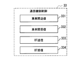
- the communication device 3 includes a communication device side BT communication unit 31, an inter-vehicle communication unit 32, and a communication device side control circuit 33. This communication device 3 is also referred to as an in-vehicle communication device.
- the communication device side BT communication unit 31 includes a transmission / reception antenna, and exchanges information by performing BT communication with the mobile terminal 2 of the main vehicle.
- the communication device side BT communication unit 31 is also referred to as a separate communication unit or an additional communication unit.
- the vehicle-to-vehicle communication unit 32 includes a transmission / reception antenna, and performs vehicle-to-vehicle communication with a communication device 3 of a surrounding vehicle to transmit and receive information by wireless communication without using a telephone network.
- the range in which vehicle-to-vehicle communication is performed differs depending on the frequency band used for wireless communication.
- Vehicle-to-vehicle communication is performed with the vehicle communication device 3.
- inter-vehicle communication is performed with a communication device 3 of a surrounding vehicle existing in a range of a radius of about 500 m around the position of the main vehicle.
- the inter-vehicle communication unit 32 transmits information at a transmission cycle (for example, every 100 milliseconds) in accordance with an instruction from the communication device side control circuit 33.
- the communicator-side control circuit 33 is configured as a normal computer, and has a well-known CPU, memory such as ROM, RAM, and EEPROM, I / O, and a bus line connecting these configurations (both shown in the figure). (Not shown).
- the communicator side control circuit 33 executes various processes by the CPU executing programs stored in advance in the ROM based on various information input from the communicator side BT communication unit 31 and the inter-vehicle communication unit 32. To do.
- the communication device side control circuit 33 may be realized as a hardware configuration as one or a plurality of ICs.
- the communicator-side control circuit 33 includes, as functional blocks, an inter-vehicle communication transmission control unit 331, an inter-vehicle communication reception control unit 332, a BT communication transmission control unit 333, and a BT communication reception.
- a control unit 334 is provided.
- the reception control unit for BT communication 334 receives the vehicle data transmitted from the mobile terminal 2 via the communication device side BT communication unit 31.
- the inter-vehicle communication transmission control unit 331 generates vehicle information of the main vehicle from the vehicle data received by the BT communication reception control unit 334 and transmits the vehicle information via the inter-vehicle communication unit 32.
- the inter-vehicle communication reception control unit 332 receives the vehicle information of the peripheral vehicle transmitted from the communication device 3 of the peripheral vehicle via the inter-vehicle communication unit 32.
- the BT communication transmission control unit 333 transmits the vehicle information received by the inter-vehicle communication reception control unit 332 to the mobile terminal 2 of the main vehicle via the communication device side BT communication unit 31.
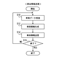
- vehicle information transmission related processing when the main vehicle information is transmitted to surrounding vehicles in the communication device side control circuit 33 of the communication device 3.
- each section is expressed as S10, for example.
- each section can be divided into a plurality of subsections, while a plurality of sections can be combined into one section.
- each section configured in this manner can be referred to as a device, module, or means.
- each of the above sections or a combination thereof includes (ii) not only a section of software combined with a hardware unit (eg, a computer) but also (ii) hardware. It can be implemented as a section of wear (e.g., integrated circuit, wiring logic circuit) with or without associated device functionality.
- the hardware section can be configured inside the microcomputer.
- the flowchart of FIG. 6 may be configured to start when the power of the communication device 3 and the portable terminal 2 is turned on.
- the reception control unit 334 for BT communication performs vehicle data reception processing, and proceeds to S12.
- the vehicle data acquisition request is transmitted to the portable terminal 2 via the communication device side BT communication unit 31, and the vehicle data returned from the portable terminal 2 in response to the acquisition request is The data is received via the communication device side BT communication unit 31.
- the communication device 3 transmits a vehicle data acquisition request to the portable terminal 2, and the BT communication reception control unit 334 receives vehicle data returned in response to the acquisition request.
- the latest vehicle data stored in the internal memory 282 may be transmitted from the portable terminal 2 at regular intervals, and the received vehicle data may be sequentially received by the BT communication reception control unit 334. .
- the vehicle-to-vehicle communication transmission control unit 331 performs vehicle information generation processing, and proceeds to S14.
- the vehicle information generation process of S12 an identification number for identifying the vehicle is given to the vehicle data received by the reception control unit 334 for BT communication, and vehicle information for transmission by inter-vehicle communication is generated.
- the device ID assigned uniquely to the communication device 3 is used as the identification number, but is not limited thereto.
- a vehicle ID assigned to each vehicle or a mobile terminal ID (for example, a manufacturing number) assigned to the mobile terminal 2 can be used.
- generated vehicle data and the transmission control part 331 for vehicle-to-vehicle communication showed the structure which implements the process which provides apparatus ID to the main vehicle information, it did not necessarily show to this. Not exclusively.
- the vehicle-to-vehicle communication transmission control unit 331 receives the sensor values of various sensors provided in the mobile terminal 2, and the vehicle-to-vehicle communication transmission control unit 331 generates main vehicle information based on the sensor values. Also good.
- the communication device 3 includes at least a satellite positioning system receiver such as the GPS receiver 24, main vehicle information is generated from the position of the communication device 3 of the main vehicle that can be detected using this receiver. It is good also as a structure.
- the azimuth angle of the main vehicle may be calculated from the position of the communication device 3 of the main vehicle by using a method similar to the above-described method of calculating from the time series data of the main vehicle position. Furthermore, when the communication device 3 is connected to a yaw rate sensor or a vehicle speed sensor (both not shown) included in the main vehicle by a CAN bus or the like, and if the sensor values of these various sensors can be obtained, Vehicle information may be generated based on the sensor value.
- the vehicle-to-vehicle communication transmission control unit 331 performs vehicle information transmission processing, and proceeds to S16.
- the vehicle information transmission process of S14 the vehicle information of the main vehicle generated in the vehicle information generation process is transmitted to surrounding vehicles via the inter-vehicle communication unit 32. Transmission of vehicle information shall be performed according to the transmission period of the vehicle-to-vehicle communication in the communication apparatus 3, such as every 100 msec.
- S16 YES If it is the end timing of the vehicle information transmission related processing in S16 (S16 YES), the flow is ended. On the other hand, when it is not the end timing of the vehicle information transmission related process (NO in S16), the process returns to S10 and the flow is repeated.
- An example of the end timing of the vehicle information transmission related process is when at least one of the power of the communication device 3 and the portable terminal 2 is turned off.
- the flowchart of FIG. 7 may be configured to start when the communication device 3 and the portable terminal 2 are turned on, as in the vehicle information transmission related process of FIG.
- the vehicle-to-vehicle communication reception control unit 332 performs vehicle information reception processing, and proceeds to S22.
- the vehicle information reception process of S20 the vehicle information transmitted by the surrounding vehicle via the inter-vehicle communication unit 32 is received.
- the vehicle information of surrounding vehicles shall be received sequentially.
- the transmission control unit 333 for BT communication performs a transfer process and proceeds to S24.
- vehicle information of surrounding vehicles is transmitted to the portable terminal 2 via the communication device side BT communication unit 31.
- vehicle information received by S20 shall be sequentially transferred to the portable terminal 2 by performing S22 sequentially, it is not restricted to this.
- a fixed transfer cycle (100 milliseconds) may be set, and vehicle information of surrounding vehicles received during that time may be transferred collectively.
- S24 YES If it is the end timing of the vehicle information reception related process in S24 (S24 YES), the flow ends. On the other hand, when it is not the end timing of the vehicle information reception related process (NO in S24), the process returns to S20 and the flow is repeated.
- An example of the end timing of the vehicle information reception related process is when the power of at least one of the communication device 3 or the portable terminal 2 is turned off.
- dangerous vehicle determination processing for determining whether or not the surrounding vehicle is a dangerous vehicle in the dangerous vehicle determination unit 286 will be described using the flowchart shown in FIG.
- the flowchart of FIG. 8 is executed for each surrounding vehicle when, for example, the vehicle information of the surrounding vehicle is received.
- the surrounding vehicle that is the target of the dangerous vehicle determination process is referred to as a target vehicle or a target other vehicle in order to distinguish it from other surrounding vehicles.
- this threshold value Ath may be another value (for example, 0.5 G), and a value obtained by determining the acceleration of the vehicle determined to be dangerous from past observation data may be used.
- a different threshold Ath may be set for each vehicle type. For example, 0.6G for passenger cars, 0.7G for vans, 0.5G for trucks less than 4t, 0.45G for trucks and buses of 4t to 10t and less. Of course, these values may be appropriately designed values.
- S30 becomes YES and the process moves to S34.
- S30 is NO and the process proceeds to S31.
- the traveling speed of the target vehicle is greater than a predetermined threshold value Vth.
- the threshold value Vth may be, for example, the legal speed of the road on which the target vehicle is traveling.
- the legal speed of the road on which the target vehicle is traveling may be determined based on the type of road on which the target vehicle is traveling from map data stored in the memory 26.
- S31 when the traveling speed of the target vehicle is higher than Vth, S31 becomes YES and the process proceeds to S34.
- S31 is NO and the process proceeds to S32.
- a predetermined threshold value is added to the average value (average traveling speed or average speed) of the traveling speeds of other surrounding vehicles that travel around the target vehicle (mainly front and rear). It is determined whether or not the value is greater than the specified value.
- the threshold value Wth is 10 km / h as an example, but may be a value such as 5 km / h, or may be a value determined according to the average speed (20% of the average speed).
- the vehicle has an azimuth angle.
- the range in the front-rear direction of the target vehicle is not limited to 50 m, and may be other values, for example, a distance proportional to the traveling speed of the target vehicle.
- the azimuth angle condition has been made in view of the following concerns. For example, at an intersection or the like, there are a mixture of vehicles that are stopped and vehicles that are traveling, so if the average speed is calculated using all these vehicles as a population, it becomes an inappropriate value.
- the azimuth difference between the vehicle forming the population for calculating the average speed and the target vehicle is set to 10 degrees or less. Of course, other values (for example, 5 degrees) may be used. .
- the above-described front-rear direction is not limited to the front and back, but includes a range including diagonally forward and diagonally rear, but is not limited thereto.
- the vehicle that makes the population for calculating the average speed is a vehicle that travels in the same lane as the target vehicle, so that the average speed can be calculated with higher accuracy. This is because even if the road is the same, the speed of the flow of the vehicle may be different if the lane is different.
- traveling lanes are equal or not is calculated from a vehicle position and azimuth angle of the target vehicle by calculating a straight line extending the target vehicle in the longitudinal direction of the target vehicle, and the shortest distance from the surrounding vehicle of the target vehicle to the straight line is within 1 m. In some cases, it may be determined that the traveling lanes are equal. Moreover, you may determine whether the driving
- S32 when the traveling speed of the target vehicle is larger than the value obtained by adding a predetermined threshold (Wth) to the average speed of the vehicle traveling around the target vehicle, S32 becomes YES and the process proceeds to S34.
- Wth predetermined threshold
- S32 when the traveling speed of the target vehicle is equal to or less than the value obtained by adding a predetermined threshold (Wth) to the average speed of the vehicles traveling around the target vehicle, S32 is NO and the process proceeds to S33. If there is no suitable vehicle around the target vehicle and the average speed cannot be calculated, S32 is NO and the process proceeds to S33.
- the threshold Yth is 0.07 rad / sec ( ⁇ 4 deg / sec), but may be other values, and is a value obtained from past observation data of the azimuth velocity of the vehicle determined to be dangerous. May be used.
- S33 when the azimuth velocity of the target vehicle is larger than the threshold value Yth, S33 becomes YES and proceeds to S34.
- S33 is NO and the process proceeds to S35.
- the dangerous vehicle determination unit 286 stores, in the internal memory 282, the identification ID of the surrounding vehicle determined as the dangerous vehicle, separately from the identification ID of the normal vehicle so that it can be recognized as a dangerous vehicle.
- the dangerous vehicle determination unit 286 stores the identification ID of the surrounding vehicle determined as a normal vehicle in the internal memory 282 so that it can be recognized as a normal vehicle.
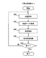
- peripheral vehicle display-related processes for displaying information on the surrounding vehicles (positions of the surrounding vehicles, whether or not the vehicle is dangerous, etc.) on the display 27.
- This flowchart is started when, for example, the power of the communication device 3 and the portable terminal 2 is turned on.
- a position acquisition process is performed, and the process proceeds to S42.
- the map image drawing unit 287 reads the main vehicle position information stored in the internal memory 282 with the latest time stamp (that is, the latest main vehicle position information).
- the map image drawing unit 287 performs map data acquisition processing, and proceeds to S44.
- map data acquisition process of S41 map data near the current main vehicle position is read from the memory 26.
- the range of the map data read from the memory 26 is determined by the current position of the main vehicle and the display scale of the map image.
- the map image drawing unit 287 performs the map image drawing process and proceeds to S46.
- a map image is generated from the map data read in S41 so that the current main vehicle position is arranged near the center of the screen.
- the surrounding vehicle display unit 288 performs the surrounding vehicle drawing process and proceeds to S48.
- the surrounding vehicle drawing process of S46 the surrounding vehicle display unit 288 superimposes the mark representing the position and azimuth of the surrounding vehicle identified for each vehicle by the vehicle identifying unit 285 on the map image generated in S46. And draw.
- the vehicle is displayed with a mark having a different display mode such as a color and a shape from the mark of the normal vehicle.
- A represents the main vehicle
- B1 to B6 represent surrounding vehicles for the main vehicle.
- Each of A and B1 to B6 includes the dangerous vehicle notification device 1, and all of them are in a range where wireless communication can be performed by the communication device 3.
- B1 to B4 are normal vehicles
- B5 and B6 are dangerous vehicles.
- the normal vehicles B1 to B4 are represented by isosceles triangles as shown in FIG. 11, and each vehicle travels in the direction of the apex of the isosceles triangle. That is, the direction of the isosceles triangle represents the azimuth angle of the vehicle.
- the marks indicating these normal vehicles B1 to B4 are displayed in gray, for example.
- the main vehicle A is arranged near the center of the screen (slightly below the center) and is displayed with a mark different from that of the normal vehicle and the dangerous vehicle so that it can be distinguished from the surrounding vehicles.
- the main vehicle may be displayed in blue.
- the dangerous vehicles B5 and B6 are displayed as isosceles triangles painted in, for example, yellow, orange, red, etc. so that it can be understood at a glance that they are dangerous vehicles. Further, an exclamation mark or the like may be displayed inside.
- an isosceles triangle is used as a mark indicating the position and azimuth of each vehicle, but other figures such as arrows may be used.
- the driver of the main vehicle A can recognize at a glance whether or not the surrounding vehicle is a dangerous driving vehicle. For example, when the surrounding vehicle running in front of the main vehicle is a dangerous vehicle, it is possible to take measures such as making the inter-vehicle distance longer than usual, and further safe driving can be attempted. Become.
- the operation and effect in the present embodiment are as follows. First, according to the above configuration, whether or not the other vehicle is a dangerous driving vehicle (that is, a dangerous vehicle) is determined based on the other vehicle determination information transmitted by the other vehicle. However, the dangerous vehicle is displayed in a display mode different from other vehicles that are not dangerous vehicles. The driver of the main vehicle can recognize whether or not the other vehicle traveling around the vehicle is a dangerous driving vehicle by looking at the display. Therefore, it is possible to notify the driver of the main vehicle whether or not the surrounding vehicle is driving dangerously.
- a dangerous driving vehicle that is, a dangerous vehicle
- the present embodiment it is configured such that whether the surrounding vehicle is a dangerous vehicle is determined by the main vehicle on the receiving side.
- a configuration is also conceivable in which, in the surrounding vehicle on the transmission side, it is determined whether or not the surrounding vehicle itself is a dangerous vehicle and the determination result is transmitted to the main vehicle.
- the determination criteria for determining the dangerous vehicle that is, the above-described various threshold values
- the reliability with respect to the determination result transmitted by the surrounding vehicle is lowered.
- whether or not the surrounding vehicle is a dangerous vehicle is determined by the main vehicle on the receiving side, thereby improving the reliability of whether or not the vehicle is a dangerous vehicle. it can. Further, if the driver of the main vehicle can set various threshold values (Ath, Vth, Wth, and Yth) used for determining whether or not the other vehicle is driving dangerously, the driver's preference A dangerous vehicle can be determined accordingly.
- the communication area since the area that can be used for vehicle-to-vehicle communication is limited, when the determination result is separately transmitted in addition to the vehicle information such as acceleration, the communication area may be insufficient. However, regarding vehicle information such as acceleration, since an area used in inter-vehicle communication has already been secured, there is no fear of lack of a communication area. Therefore, as in this embodiment, the surrounding vehicle transmits vehicle information of the vehicle and determines whether or not the main vehicle on the receiving side is a dangerous vehicle, thereby making the communication area more efficient. The present embodiment can be implemented more smoothly.
- the traveling speed of the target vehicle is compared with the average value (average speed) of the traveling speeds of other surrounding vehicles that travel around the target vehicle.
- the present invention is not limited to this. Whether or not the vehicle is a dangerous vehicle may be determined based on other statistical criteria. For example, in a normal distribution in which the traveling speed of other surrounding vehicles traveling around the target vehicle is a population, when the traveling speed of the target vehicle falls outside the range of minus 1 ⁇ to plus 1 ⁇ , It is good also as a structure to determine.
- the surrounding vehicles are distinguished in two stages, that is, a normal vehicle and a dangerous vehicle, but the present invention is not limited to this.
- a surrounding vehicle that exceeds 10 km / h and a surrounding vehicle that exceeds 30 km / h with respect to a threshold value Vth for determining whether or not the vehicle is performing dangerous driving based on the traveling speed may be a dangerous vehicle.
- the travel speed threshold Vth may be further divided into a plurality of stages, and the degree of danger may be evaluated in a plurality of stages.
- the dangerous vehicle display unit 288A displays in different display modes depending on the danger level of the surrounding vehicle. For example, the higher the degree of danger, the more the display mode is conspicuous for the driver of the main vehicle, such as the red color or blinking at a faster cycle, and the closer the degree of danger, the closer to the normal vehicle. Furthermore, the danger level of the dangerous vehicle may be reduced with the passage of time, and the surrounding vehicle display unit 288 may bring the display mode closer to the mark of the normal vehicle in accordance with the danger level.
- the configuration is described in which the degree of danger is evaluated in a plurality of stages by taking the traveling speed as an example. However, for other accelerations and azimuth angular velocities, similarly, the degree of danger is evaluated using a threshold of a plurality of stages. May be.
- the dangerous vehicle determination unit 286 may determine whether or not the main vehicle itself is a dangerous vehicle from the vehicle information of the main vehicle. Accordingly, the dangerous vehicle display unit 288A displays a display mode of an icon indicating the main vehicle so that it can be recognized that the vehicle is a dangerous vehicle. As a result, the driver of the main vehicle himself / herself can be made aware of how it is viewed from the surrounding vehicles, and the driver of the main vehicle can be encouraged to try safe driving.
- the dangerous vehicle determination unit 286 may determine whether or not the surrounding vehicle (simply a target vehicle) is meandering from the time-series data of the azimuth angular velocity and the direction change of the surrounding vehicle. Whether or not the meandering operation is performed may be determined as the meandering operation when, for example, the azimuth velocity (or azimuth angle) vibrates in a certain width or more within a certain time and the vibrations exceed a certain width.
- the dangerous vehicle display unit 288A may display in a display mode different from that of the normal vehicle and other dangerous vehicles.
- the map data is stored in the memory 26.
- the present invention is not limited to this.
- the mobile terminal 2 can use a mobile phone line or the like, a configuration may be adopted in which necessary map data is acquired by accessing an external server (not shown).
- the program 4 may also be stored on an external server.
Landscapes
- Engineering & Computer Science (AREA)
- Physics & Mathematics (AREA)
- General Physics & Mathematics (AREA)
- Theoretical Computer Science (AREA)
- Educational Technology (AREA)
- Educational Administration (AREA)
- Business, Economics & Management (AREA)
- Mathematical Physics (AREA)
- Radar, Positioning & Navigation (AREA)
- Remote Sensing (AREA)
- Life Sciences & Earth Sciences (AREA)
- Ecology (AREA)
- Traffic Control Systems (AREA)
- Instructional Devices (AREA)
Priority Applications (1)
| Application Number | Priority Date | Filing Date | Title |
|---|---|---|---|
| US14/782,577 US9601017B2 (en) | 2013-04-09 | 2014-04-03 | Reckless-vehicle reporting apparatus, reckless-vehicle reporting program product, and reckless-vehicle reporting method |
Applications Claiming Priority (2)
| Application Number | Priority Date | Filing Date | Title |
|---|---|---|---|
| JP2013081530A JP6123443B2 (ja) | 2013-04-09 | 2013-04-09 | 危険車両通知装置、危険車両通知プログラム、危険車両通知プログラムを記録した記録媒体 |
| JP2013-081530 | 2013-04-09 |
Publications (1)
| Publication Number | Publication Date |
|---|---|
| WO2014167810A1 true WO2014167810A1 (ja) | 2014-10-16 |
Family
ID=51689232
Family Applications (1)
| Application Number | Title | Priority Date | Filing Date |
|---|---|---|---|
| PCT/JP2014/001951 Ceased WO2014167810A1 (ja) | 2013-04-09 | 2014-04-03 | 危険車両通知装置、危険車両通知プログラム製品、危険車両通知方法 |
Country Status (3)
| Country | Link |
|---|---|
| US (1) | US9601017B2 (https=) |
| JP (1) | JP6123443B2 (https=) |
| WO (1) | WO2014167810A1 (https=) |
Cited By (2)
| Publication number | Priority date | Publication date | Assignee | Title |
|---|---|---|---|---|
| JP2016099778A (ja) * | 2014-11-20 | 2016-05-30 | パナソニックIpマネジメント株式会社 | 端末装置 |
| JP2020030689A (ja) * | 2018-08-23 | 2020-02-27 | トヨタ自動車株式会社 | 情報システム、情報処理方法およびプログラム |
Families Citing this family (19)
| Publication number | Priority date | Publication date | Assignee | Title |
|---|---|---|---|---|
| JP5990553B2 (ja) * | 2014-04-22 | 2016-09-14 | 株式会社日立製作所 | 携帯端末用プログラム、携帯端末、自動車運転特性診断システム、自動車加速度算出方法 |
| KR102573705B1 (ko) * | 2015-11-24 | 2023-09-04 | 삼성디스플레이 주식회사 | 디스플레이 제어 시스템 |
| WO2017123719A1 (en) * | 2016-01-13 | 2017-07-20 | Copen Travis | Wireless tilt sensor system and method |
| JP6848198B2 (ja) * | 2016-03-31 | 2021-03-24 | 日本電気株式会社 | 運転状態判定装置、運転状態判定方法、プログラム |
| JP2018151716A (ja) * | 2017-03-10 | 2018-09-27 | オムロン株式会社 | 情報処理装置、リスク回避通知方法、およびリスク回避通知プログラム |
| CN110431610B (zh) * | 2017-03-31 | 2021-12-21 | 本田技研工业株式会社 | 车载装置、信息管理系统及方法 |
| US11328210B2 (en) | 2017-12-29 | 2022-05-10 | Micron Technology, Inc. | Self-learning in distributed architecture for enhancing artificial neural network |
| US20210316720A1 (en) * | 2018-01-09 | 2021-10-14 | State Farm Mutual Automobile Insurance Company | Vehicle collision alert system and method for directing collision avoidance action |
| JP2018077908A (ja) * | 2018-01-31 | 2018-05-17 | エイディシーテクノロジー株式会社 | 通信装置 |
| US10522038B2 (en) * | 2018-04-19 | 2019-12-31 | Micron Technology, Inc. | Systems and methods for automatically warning nearby vehicles of potential hazards |
| JPWO2020065708A1 (ja) * | 2018-09-25 | 2021-08-30 | 株式会社ウフル | コンピュータシステム、危険運転車両通知方法及びプログラム |
| JP7292484B2 (ja) * | 2018-11-28 | 2023-06-16 | 京セラ株式会社 | 画像処理装置、撮像装置及び移動体 |
| JP7197428B2 (ja) * | 2019-05-08 | 2022-12-27 | 日立建機株式会社 | 車両制御システム |
| DE102019117689B4 (de) * | 2019-07-01 | 2025-10-23 | Bayerische Motoren Werke Aktiengesellschaft | Verfahren und Steuereinheit zur Darstellung einer Verkehrssituation durch Ausblenden von Verkehrsteilnehmer-Symbolen |
| JP7379273B2 (ja) * | 2020-06-01 | 2023-11-14 | 日立建機株式会社 | 車両制御システム |
| JP7809647B2 (ja) * | 2020-11-16 | 2026-02-02 | 株式会社小糸製作所 | 車両用表示システム |
| JP7607473B2 (ja) * | 2021-03-10 | 2024-12-27 | パイオニア株式会社 | 携帯端末、測位方法、プログラム及び記憶媒体 |
| KR102588983B1 (ko) * | 2022-03-29 | 2023-10-17 | 포티투닷 주식회사 | 차량 내 인터페이스를 제공하는 장치 및 방법 |
| CN115376115B (zh) * | 2022-10-25 | 2023-01-17 | 中国第一汽车股份有限公司 | 鲁莽驾驶行为标记方法、车辆、云端服务器和存储介质 |
Citations (3)
| Publication number | Priority date | Publication date | Assignee | Title |
|---|---|---|---|---|
| JP2002211265A (ja) * | 2001-01-16 | 2002-07-31 | Data Tec:Kk | 車両の運転技術診断システム及びその構成用品、運転技術診断方法 |
| JP2003346287A (ja) * | 2002-05-28 | 2003-12-05 | Koyo Seiko Co Ltd | 車両及びこれに用いられる情報通信方法、並びに車両用情報通信システム |
| JP2011129106A (ja) * | 2009-11-19 | 2011-06-30 | Sanyo Electric Co Ltd | 無線装置 |
Family Cites Families (7)
| Publication number | Priority date | Publication date | Assignee | Title |
|---|---|---|---|---|
| JP4111773B2 (ja) | 2002-08-19 | 2008-07-02 | アルパイン株式会社 | ナビゲーション装置の地図表示方法 |
| KR100498965B1 (ko) * | 2003-04-22 | 2005-07-01 | 삼성전자주식회사 | 차량간 임시 무선 네트워크를 이용한 차량 운행정보 교환방법 및 시스템 |
| US20060291482A1 (en) * | 2005-06-23 | 2006-12-28 | Cisco Technology, Inc. | Method and apparatus for providing a metropolitan mesh network |
| US7822384B2 (en) * | 2006-10-12 | 2010-10-26 | At&T Intellectual Property I, L.P. | Methods, systems, and computer program products for providing mobile ad hoc cooperative communication systems and related devices |
| US8522013B2 (en) * | 2009-08-31 | 2013-08-27 | Telcordia Technologies, Inc. | System and methods to perform public key infrastructure (PKI) operations in vehicle networks using one-way communications infrastructure |
| US8447231B2 (en) * | 2010-10-29 | 2013-05-21 | GM Global Technology Operations LLC | Intelligent telematics information dissemination using delegation, fetch, and share algorithms |
| JP2014203399A (ja) | 2013-04-09 | 2014-10-27 | 株式会社デンソー | ドライバ情報表示装置、ドライバ情報表示プログラム、ドライバ情報表示プログラムを記録した記録媒体 |
-
2013
- 2013-04-09 JP JP2013081530A patent/JP6123443B2/ja active Active
-
2014
- 2014-04-03 US US14/782,577 patent/US9601017B2/en active Active
- 2014-04-03 WO PCT/JP2014/001951 patent/WO2014167810A1/ja not_active Ceased
Patent Citations (3)
| Publication number | Priority date | Publication date | Assignee | Title |
|---|---|---|---|---|
| JP2002211265A (ja) * | 2001-01-16 | 2002-07-31 | Data Tec:Kk | 車両の運転技術診断システム及びその構成用品、運転技術診断方法 |
| JP2003346287A (ja) * | 2002-05-28 | 2003-12-05 | Koyo Seiko Co Ltd | 車両及びこれに用いられる情報通信方法、並びに車両用情報通信システム |
| JP2011129106A (ja) * | 2009-11-19 | 2011-06-30 | Sanyo Electric Co Ltd | 無線装置 |
Non-Patent Citations (1)
| Title |
|---|
| YUJI HATTA ET AL.: "Vehicular- Collision Avoidance Support System (VCASS) : Development of collision warning system based on dynamic position estimation", IEICE TECHNICAL REPORT IN 2004-203, vol. 104, no. 691, 24 February 2005 (2005-02-24), pages 23 - 28 * |
Cited By (3)
| Publication number | Priority date | Publication date | Assignee | Title |
|---|---|---|---|---|
| JP2016099778A (ja) * | 2014-11-20 | 2016-05-30 | パナソニックIpマネジメント株式会社 | 端末装置 |
| JP2020030689A (ja) * | 2018-08-23 | 2020-02-27 | トヨタ自動車株式会社 | 情報システム、情報処理方法およびプログラム |
| JP7155750B2 (ja) | 2018-08-23 | 2022-10-19 | トヨタ自動車株式会社 | 情報システムおよびプログラム |
Also Published As
| Publication number | Publication date |
|---|---|
| US9601017B2 (en) | 2017-03-21 |
| JP6123443B2 (ja) | 2017-05-10 |
| US20160042642A1 (en) | 2016-02-11 |
| JP2014203398A (ja) | 2014-10-27 |
Similar Documents
| Publication | Publication Date | Title |
|---|---|---|
| JP6123443B2 (ja) | 危険車両通知装置、危険車両通知プログラム、危険車両通知プログラムを記録した記録媒体 | |
| US20220289228A1 (en) | Hmi control device, hmi control method, and hmi control program product | |
| JP6662828B2 (ja) | 運転支援システム、運転支援装置および運転支援方法 | |
| US10336257B2 (en) | Rear vision system for a vehicle and method of using the same | |
| US11508161B2 (en) | Driving support system and server device | |
| JP5472163B2 (ja) | 速度規制値通知装置及び速度規制値通知システム | |
| JP6551209B2 (ja) | 運転支援装置 | |
| JP4992755B2 (ja) | 交差点運転支援システム、車載器、及び、路側機 | |
| JP5257252B2 (ja) | 運転支援装置および運転支援システム | |
| US20080015772A1 (en) | Drive-assist information providing system for driver of vehicle | |
| WO2014208081A1 (ja) | ヘッドアップディスプレイ及びプログラム製品 | |
| EP3207494B1 (en) | Systems and methods for traffic sign validation | |
| CN111161551B (zh) | 用于检测、警报和响应紧急车辆的设备、系统和方法 | |
| CN107054218A (zh) | 标识信息显示装置和方法 | |
| JP2012123625A (ja) | 車両運転推定システム | |
| WO2018103848A1 (en) | Systems and methods for regulation of autonomous cruise control | |
| JP2009187413A (ja) | 車載装置、車両走行支援システム | |
| JP2011221573A (ja) | 運転支援装置および運転支援システム | |
| JP2019109707A (ja) | 表示制御装置、表示制御方法および車両 | |
| JP2009037457A (ja) | 運転支援システム | |
| WO2014167809A1 (ja) | ドライバ情報表示装置、ドライバ情報表示プログラム製品、ドライバ情報表示方法 | |
| JP2008210256A (ja) | 運転支援装置 | |
| JP2014115931A (ja) | 運転支援装置、運転支援制御装置および運転支援制御方法 | |
| JP2004341893A (ja) | 車載システム | |
| JP4239856B2 (ja) | 通信装置及びプログラム |
Legal Events
| Date | Code | Title | Description |
|---|---|---|---|
| 121 | Ep: the epo has been informed by wipo that ep was designated in this application |
Ref document number: 14783162 Country of ref document: EP Kind code of ref document: A1 |
|
| WWE | Wipo information: entry into national phase |
Ref document number: 14782577 Country of ref document: US |
|
| NENP | Non-entry into the national phase |
Ref country code: DE |
|
| 122 | Ep: pct application non-entry in european phase |
Ref document number: 14783162 Country of ref document: EP Kind code of ref document: A1 |