WO2014167810A1 - Reckless vehicle notifying device, reckless vehicle notifying program product, and reckless vehicle notifying method - Google Patents
Reckless vehicle notifying device, reckless vehicle notifying program product, and reckless vehicle notifying method Download PDFInfo
- Publication number
- WO2014167810A1 WO2014167810A1 PCT/JP2014/001951 JP2014001951W WO2014167810A1 WO 2014167810 A1 WO2014167810 A1 WO 2014167810A1 JP 2014001951 W JP2014001951 W JP 2014001951W WO 2014167810 A1 WO2014167810 A1 WO 2014167810A1
- Authority
- WO
- WIPO (PCT)
- Prior art keywords
- vehicle
- dangerous
- determination
- unit
- target
- Prior art date
Links
Images


Classifications
-
- G—PHYSICS
- G08—SIGNALLING
- G08G—TRAFFIC CONTROL SYSTEMS
- G08G1/00—Traffic control systems for road vehicles
- G08G1/123—Traffic control systems for road vehicles indicating the position of vehicles, e.g. scheduled vehicles; Managing passenger vehicles circulating according to a fixed timetable, e.g. buses, trains, trams
- G08G1/133—Traffic control systems for road vehicles indicating the position of vehicles, e.g. scheduled vehicles; Managing passenger vehicles circulating according to a fixed timetable, e.g. buses, trains, trams within the vehicle ; Indicators inside the vehicles or at stops
- G08G1/137—Traffic control systems for road vehicles indicating the position of vehicles, e.g. scheduled vehicles; Managing passenger vehicles circulating according to a fixed timetable, e.g. buses, trains, trams within the vehicle ; Indicators inside the vehicles or at stops the indicator being in the form of a map
-
- G—PHYSICS
- G08—SIGNALLING
- G08G—TRAFFIC CONTROL SYSTEMS
- G08G1/00—Traffic control systems for road vehicles
- G08G1/16—Anti-collision systems
- G08G1/161—Decentralised systems, e.g. inter-vehicle communication
- G08G1/162—Decentralised systems, e.g. inter-vehicle communication event-triggered
-
- G—PHYSICS
- G09—EDUCATION; CRYPTOGRAPHY; DISPLAY; ADVERTISING; SEALS
- G09B—EDUCATIONAL OR DEMONSTRATION APPLIANCES; APPLIANCES FOR TEACHING, OR COMMUNICATING WITH, THE BLIND, DEAF OR MUTE; MODELS; PLANETARIA; GLOBES; MAPS; DIAGRAMS
- G09B29/00—Maps; Plans; Charts; Diagrams, e.g. route diagram
- G09B29/003—Maps
- G09B29/006—Representation of non-cartographic information on maps, e.g. population distribution, wind direction, radiation levels, air and sea routes
-
- G—PHYSICS
- G09—EDUCATION; CRYPTOGRAPHY; DISPLAY; ADVERTISING; SEALS
- G09B—EDUCATIONAL OR DEMONSTRATION APPLIANCES; APPLIANCES FOR TEACHING, OR COMMUNICATING WITH, THE BLIND, DEAF OR MUTE; MODELS; PLANETARIA; GLOBES; MAPS; DIAGRAMS
- G09B29/00—Maps; Plans; Charts; Diagrams, e.g. route diagram
- G09B29/10—Map spot or coordinate position indicators; Map reading aids
Definitions
- This disclosure relates to a technique for notifying a driver of other dangerous vehicles existing around a vehicle using inter-vehicle communication.
- Patent Document 1 a technique for displaying the position and traveling direction of a vehicle (that is, a surrounding vehicle) existing around a vehicle, acquired by using inter-vehicle communication, superimposed on a map image. There is.
- An object of the present disclosure is to provide a dangerous vehicle notification device, a dangerous vehicle notification program product, and a dangerous vehicle notification method capable of notifying a driver of a vehicle whether or not a surrounding vehicle is driving dangerously. It is in.
- the dangerous vehicle notification device is provided as follows.
- the dangerous vehicle notification device is mounted on a vehicle and transmits / receives data via wireless communication to / from another dangerous vehicle notification device that is mounted on each of a plurality of other vehicles different from the vehicle and has the same function.
- the dangerous vehicle notification device transmits a position detection unit that detects the position of the vehicle, position data indicating the position of the vehicle, and a position indicating the position of each other vehicle transmitted by each other vehicle.
- an in-vehicle communication device for receiving data.
- the dangerous vehicle notification device is (i) a mark display processing unit that displays on the display a mark indicating the position of each other vehicle based on the position data of each other vehicle received by the in-vehicle communication device, (ii) A determination information acquisition unit for acquiring determination information used to determine whether or not the vehicle is driving dangerously; (iii) the determination information acquired by the determination information acquisition unit; A transmission control unit that transmits via an in-vehicle communication device, (iv) the information for determination used to determine whether or not each other vehicle transmits a dangerous driving for each other vehicle, A reception control unit that receives via an in-vehicle communication device; (v) a dangerous vehicle determination that determines whether or not each other vehicle is driving dangerously from the determination information of each other vehicle received by the reception control unit; A part.
- the dangerous vehicle notification device determines that the mark indicating the position of the target other vehicle that is the other vehicle determined to be dangerously driven by the dangerous vehicle determination unit is dangerously driven.
- a dangerous vehicle display processing unit for displaying in a first display mode different from the second display mode for displaying the mark indicating the position of each other vehicle that has not been provided.
- the dangerous vehicle determination unit of the dangerous vehicle notification device mounted on the vehicle is a vehicle in which the other vehicle is performing dangerous driving based on the determination information of the other vehicle transmitted by the other vehicle. It is determined whether or not. Then, the target other vehicle determined to be a vehicle that is driving dangerously is displayed on the display in a display mode (also referred to as a display format) that is different from that of the other vehicle that is determined not to perform other dangerous driving.
- the driver of the vehicle can recognize whether or not the other vehicle traveling around the vehicle is a dangerous driving vehicle by looking at the display. Therefore, according to the above configuration, it is possible to notify the driver of the vehicle whether or not the surrounding vehicle is driving dangerously.
- the dangerous vehicle notification program product is provided as follows. That is, the computer is included in the dangerous vehicle notification device of the first example, the determination information acquisition unit, the transmission control unit, the reception control unit, the mark display processing unit, the dangerous vehicle determination unit, And a dangerous vehicle notification program product recorded in a computer-readable non-transition storage medium, including instructions for functioning as the dangerous vehicle display processing unit.
- the dangerous vehicle notification program product is provided as follows. That is, the determination information acquisition unit, the transmission control unit, the reception control unit, the mark display processing unit, and the dangerous vehicle determination, which are executed by a computer and included in the dangerous vehicle notification device of the first example. And a dangerous vehicle notification method for realizing the function as the dangerous vehicle display processing unit.
- FIG. 1 is a diagram illustrating an example of a schematic configuration of a vehicle-to-vehicle communication system (hereinafter, referred to as a dangerous vehicle notification system) 100 to which a dangerous vehicle notification device 1 according to the present disclosure is applied.
- the dangerous vehicle notification system 100 includes a dangerous vehicle notification device 1 that is used one by one for each of a plurality of vehicles.
- the plurality of vehicles include a vehicle A and a plurality of vehicles B that are not shown in FIG.
- Vehicle A is referred to as a main vehicle or simply a vehicle, and vehicle B is also referred to as another vehicle.
- the relationship between these main vehicles and other vehicles is relatively determined. If one vehicle B is the main vehicle, the vehicle A naturally becomes another vehicle for the vehicle B.
- the host vehicle for the certain apparatus it is also referred to as the host vehicle for the certain apparatus.
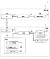
- FIG. 2 is a diagram illustrating an example of a schematic configuration of the dangerous vehicle notification device 1.
- the dangerous vehicle notification device 1 includes a mobile terminal 2 and a communication device 3.
- the mobile terminal 2 obtains data to be transmitted to other vehicles (hereinafter simply referred to as surrounding vehicles) existing around the main vehicle where the mobile terminal 2 is mounted, and displays the data received from the surrounding vehicles on the display 27. It is a device for notifying the driver of the main vehicle via.
- the periphery of the main vehicle means a range in which the communication device 3 described later can perform wireless communication.
- the mobile terminal 2 may be configured to use a known multifunction mobile phone such as a smartphone. As an example, the mobile terminal 2 is temporarily fixed in the passenger compartment so that the driver of the main vehicle can visually recognize the display 27 of the mobile terminal 2.
- the mounting orientation of the mobile terminal 2 with respect to the main vehicle (the orientation of the mobile terminal 2 with respect to the front-rear direction of the main vehicle, the angle of the own terminal with respect to the horizontal plane, etc.) is set in the mobile terminal 2 in advance.
- the display 27 is directed to the driver's seat at 110 degrees with respect to the horizontal plane, and the mapping component to the horizontal plane in the vertical direction of the mobile terminal 2 matches the front-rear direction of the main vehicle. Install.
- the mounting posture of the mobile terminal 2 on the vehicle is not limited to this, and may be set by a driver.
- the mobile terminal 2 includes a mobile side Bluetooth (registered trademark, hereinafter referred to as BT) communication unit 21, a detection unit 22, a memory 26, a display 27, and a mobile side control circuit 28 in order to realize the above-described device function. I have.
- BT mobile side Bluetooth
- the portable-side BT communication unit 21 includes a transmission / reception antenna and exchanges information with the communication device 3 of the main vehicle by performing communication according to the Bluetooth standard (hereinafter referred to as BT communication).
- BT communication the Bluetooth standard
- the configuration in which the communication between the mobile terminal 2 and the communication device 3 is performed by BT communication is shown, but the configuration is not necessarily limited thereto.
- it may be configured to perform wireless communication according to short-range wireless communication standards such as ZigBee (registered trademark) or wireless LAN standards such as IEEE 802.11, or may be configured to perform wired communication such as USB communication.
- the portable BT communication unit 21 is also referred to as a separate communication unit or an additional communication unit.
- the detection unit 22 acquires various data for generating information for determining whether or not the driving of the main vehicle is a safe driving.
- the detection unit 22 includes a GPS receiver 221 that receives radio waves from a GPS (Global Positioning System) satellite, an acceleration sensor 222 that detects acceleration acting on the terminal, an angular velocity acting on the terminal, A gyro sensor 223 for detecting an angle is provided.
- GPS Global Positioning System
- the memory 26 is electrically rewritable for storing the map data for route guidance and the program 4 for operating a portable terminal such as a known multi-function mobile phone as the portable terminal 2 according to the present embodiment. It is a non-volatile memory.
- the memory 26 may be a storage medium that is removable from the portable terminal 2 such as an SD card.
- the memory 26 is configured not to erase the stored data unless an instruction to erase is given by an operation by the driver.
- the program 4 for causing a known mobile terminal to operate as the mobile terminal 2 according to the present embodiment may be installed in a storage area such as a ROM provided in the mobile-side control circuit 28 described later. This program 4 is also referred to as a dangerous vehicle notification program product.
- the display 27 displays text and images based on signals input from the mobile control circuit 28.
- the display 27 is capable of full-color display and can be configured using a TFT liquid crystal display, an organic EL display, or the like.
- the portable-side control circuit 28 is configured as a normal computer, and has a well-known CPU, memory such as ROM, RAM, and EEPROM, I / O, and a bus line for connecting these configurations (all not shown). Etc.).
- the portable side control circuit 28 executes various processes by the CPU executing programs stored in advance in the ROM or the memory 26 based on various information input from the portable side BT communication unit 21 and the detection unit 22.
- the portable control circuit 28 may be realized as a hardware configuration as one or a plurality of ICs.
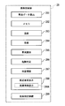
- the portable side control circuit 28 includes a vehicle data calculation unit 281, an internal memory 282, and a transmission control unit 283 as functional blocks for processing data to be transmitted to surrounding vehicles.
- a reception control unit 284 As a functional block for processing data received from surrounding vehicles, a reception control unit 284, a vehicle identification unit 285, a dangerous vehicle determination unit 286, a map image drawing unit 287, a surrounding vehicle display unit 288, and a risk determination continuation unit 289.
- the internal memory 282 is constructed in an electrically rewritable memory such as a RAM or an EEPROM.
- the vehicle data calculation unit 281 calculates various data (vehicle data) related to the traveling state of the main vehicle from various sensor data sequentially detected by the detection unit 22 and stores the data in the internal memory 282.
- the vehicle data calculated by the vehicle data calculation unit 281 includes, for example, the position of the mobile terminal 2 (that is, the position of the main vehicle), the traveling speed of the main vehicle, the acceleration acting on the main vehicle, and the traveling direction of the main vehicle. (Hereinafter referred to as azimuth angle) and azimuth velocity.
- azimuth angle azimuth angle
- azimuth velocity azimuth velocity
- the vehicle data may be only the position and acceleration of the main vehicle.
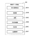
- the vehicle data calculation unit 281 includes, as shown in FIG. 4, an own terminal mounting posture detection unit 281A, an acceleration calculation unit 281B, a speed calculation unit 281C, and an azimuth angular velocity calculation unit 281D. , An azimuth angle calculation unit 281E, and a position acquisition unit 281F.
- the vehicle data calculation unit 281 can also be said to function as a determination information acquisition unit, while vehicle data is also referred to as determination information.
- the own terminal mounting posture detection unit 281A detects the mounting posture of the mobile terminal 2 with respect to the main vehicle.
- the mounting posture with respect to the main vehicle is set in advance as in the present embodiment, the set value is used, but the present invention is not limited to this.
- the portable terminal 2 provided with the acceleration sensor 222 and the gyro sensor 223, the direction of the own terminal and the inclination with respect to a horizontal surface can be detected from these sensor data by a known technique.
- the front-rear direction of the main vehicle may be detected from the time-series data of the position of the main vehicle calculated by the position acquisition unit 281F, which will be described later, and the direction of the own terminal relative to the front-rear direction may be calculated.
- the front-rear direction of the main vehicle is determined by detecting a section traveling on a straight road from the time-series data of the position of the main vehicle calculated by the position acquisition unit 281F, and indicating the moving direction when traveling on the straight section. What is necessary is just to set it as the front-back direction of a main vehicle.
- acceleration acting in the front-rear direction of the main vehicle can be obtained from sensor values such as acceleration acting on the own terminal.
- the acceleration calculation unit 281B sequentially calculates the longitudinal component of the main vehicle (hereinafter simply referred to as acceleration) from the acceleration acting on the terminal from the mounting posture detected by the terminal mounting posture detection unit 281A.
- acceleration is expressed as a positive value in the traveling direction
- the acceleration in the deceleration direction is expressed as a negative value.
- only the longitudinal component of the main vehicle in the acceleration acting on the terminal is calculated.
- the vehicle width direction component in the acceleration acting on the terminal is calculated separately. It is good also as composition to do.
- This acceleration calculation unit 281B can also be referred to as an acceleration acquisition unit.
- the speed calculation unit 281C sequentially calculates the traveling speed of the main vehicle by integrating the acceleration in the vehicle longitudinal direction calculated by the acceleration calculation unit 281B.
- the speed calculation unit 281C is also referred to as a travel speed acquisition unit.
- the azimuth angular velocity calculation unit 281D sequentially calculates the azimuth angular velocity (rad / sec) acting on the main vehicle from the mounting posture detected by the own terminal mounting posture detection unit 281A and the angular velocity change detected by the gyro sensor 223.
- This azimuth angular velocity calculation unit 281D is also referred to as an azimuth angular velocity acquisition unit.
- the azimuth angle calculation unit 281E calculates the angle change of the own terminal by integrating the angular velocity detected by the gyro sensor 223, and further, the direction of the own terminal and the direction of the main vehicle detected by the own terminal mounting posture detection unit 281A. From the relative relationship, the azimuth angle (rad) of the main vehicle is sequentially calculated.
- the position acquisition unit 281F sequentially detects the position of the main vehicle based on information obtained from each sensor such as the acceleration sensor 222 and the gyro sensor 223 in addition to the information on the position of the main vehicle received by the GPS receiver 221. Do. Since these sensors have errors of different properties, they are configured to detect the position of the main vehicle while being complemented by a plurality of sensors, but depending on the accuracy of each sensor, It may be configured in part, or may be configured using a sensor other than those described above. That is, the position acquisition unit 281F may be configured to detect the position of the main vehicle using only the GPS receiver 24. The position of the main vehicle is represented by latitude and longitude.
- the speed calculation unit 281C may calculate the travel speed by calculating the movement distance per unit time from the positions of a plurality of main vehicles arranged in time series.
- the acceleration calculation part B can handle the value which carried out the time differentiation of the running speed calculated sequentially as an acceleration.
- the azimuth angle calculation unit 281E may calculate and calculate the direction in which the approximate line obtained by the least square method extends from a plurality of positions arranged in time series, for example. Moreover, what is necessary is just to set it as the structure which calculates
- the azimuth velocity calculation unit 281D may obtain the azimuth angle sequentially calculated by the azimuth calculation unit 281E by performing time differentiation.
- the vehicle data calculated by the vehicle data calculation unit 281 as described above is stored in the internal memory 282 with information on the calculated time (that is, a time stamp).
- a time stamp information on the calculated time
- the data stored in the internal memory 282 is erased in order from the oldest information. That's fine.
- other vehicle data that has been stored for a certain period of time may be deleted.
- the transmission control unit 283 performs control for transmitting the vehicle data stored in the internal memory 282 to the communication device 3 via the portable BT communication unit 21.
- the transmission control unit 283 reads the vehicle data stored in the internal memory 282 when receiving an acquisition request for main vehicle information from the communication device 3 of the main vehicle via the portable BT communication unit 21. Then, the read vehicle data is transmitted to the communication device 3 via the portable-side BT communication unit 21.
- the data to be read is only the latest data (that is, the latest time stamp), but other past vehicle data for a plurality of time points may be read and transmitted from the latest data.
- the vehicle data is transmitted to surrounding vehicles as vehicle information to which an identification ID for identifying the vehicle is assigned.
- the reception control unit 284 receives the vehicle information of the surrounding vehicle received from the surrounding vehicle by the communication device 3 of the main vehicle via the portable side BT communication unit 21.
- the vehicle information of the surrounding vehicles includes an identification ID, a vehicle position, an azimuth angle, a traveling speed, an acceleration, an azimuth angular velocity, and the like, similarly to the vehicle information of the main vehicle.
- the vehicle identification unit 285 identifies whether the vehicle ID is transmitted from the same vehicle or from a different vehicle, based on the identification ID included in the vehicle information of the surrounding vehicle. Then, the vehicle information is classified for each vehicle and stored in the internal memory 282.
- the dangerous vehicle determination unit 286 determines, based on the vehicle information of the surrounding vehicles, whether the vehicle is in a dangerous driving (hereinafter referred to as a dangerous vehicle) for each surrounding vehicle. Details of the process for determining whether or not the surrounding vehicle is a dangerous vehicle will be described later.
- the map image drawing unit 287 reads the map data near the current main vehicle position from the memory 26 and draws the map image so that the main vehicle is displayed near the center of the screen.
- the range of the map data read from the memory 26 is determined by the current main vehicle position and the set display scale of the map image.
- the surrounding vehicle display unit 288 draws the map image drawn by the map image drawing unit 287 by superimposing marks representing the position and azimuth of the surrounding vehicle identified for each vehicle by the vehicle identification unit 285.
- the surrounding vehicle determined as the dangerous vehicle by the dangerous vehicle determination unit 286 is the mark of the normal vehicle so that it can be distinguished from the vehicle not determined as the dangerous vehicle (hereinafter referred to as a normal vehicle).
- the display is performed with marks having different display modes (or display formats) such as colors and shapes.
- the display mode for distinguishing between the normal vehicle and the dangerous vehicle is not limited to color and shape, but may be implemented by using blinking, color change, text, or the like.
- the mark representing the dangerous vehicle is displayed in front of the driver as compared with the normal vehicle. As a result, even when the marks of the surrounding vehicles are densely overlapped and displayed, the marks representing the dangerous vehicles can be displayed without being hidden.
- a function for displaying a dangerous vehicle is referred to as a dangerous vehicle display unit 288A.
- the surrounding vehicle display unit 288 is also referred to as a mark display processing unit, and the dangerous vehicle display unit 288A is also referred to as a dangerous vehicle display processing unit.
- the danger determination continuation unit 289 maintains the determination that the vehicle is a dangerous vehicle as long as the vehicle that has been determined to be a dangerous vehicle by the dangerous vehicle determination unit 286 is communicating with the surrounding vehicle. . This is because a vehicle that has once made a dangerous driving is considered to have a high possibility of dangerous driving again even if it temporarily stops dangerous driving. That is, the danger determination continuation unit 289 can notify the driver of the main vehicle A of a vehicle that is not currently in a dangerous driving but is likely to perform a dangerous driving again. Note that a dangerous vehicle determination process, which will be described later, is not performed on a vehicle that has been determined to be a dangerous vehicle as long as the determination that the vehicle is a dangerous vehicle is maintained in the danger determination continuation unit 289.
- the condition for returning from a dangerous vehicle to a normal vehicle is, for example, that the vehicle information from the dangerous vehicle cannot be received for a certain time (for example, 30 seconds) or more, for example, when the dangerous vehicle goes out of a range where wireless communication with the main vehicle is possible. And when.
- a configuration may be adopted in which the vehicle is returned from the dangerous vehicle to the normal vehicle after a predetermined time (for example, 1 minute) has elapsed since the vehicle is determined to be dangerous.
- the communication device 3 transmits and receives information to and from the communication device 3 of the surrounding vehicle by inter-vehicle communication.
- the communicator 3 is not limited to the configuration mounted on the vehicle, but may be configured such that a portable device is brought into the vehicle by each driver.
- the communication device 3 includes a communication device side BT communication unit 31, an inter-vehicle communication unit 32, and a communication device side control circuit 33. This communication device 3 is also referred to as an in-vehicle communication device.
- the communication device side BT communication unit 31 includes a transmission / reception antenna, and exchanges information by performing BT communication with the mobile terminal 2 of the main vehicle.
- the communication device side BT communication unit 31 is also referred to as a separate communication unit or an additional communication unit.
- the vehicle-to-vehicle communication unit 32 includes a transmission / reception antenna, and performs vehicle-to-vehicle communication with a communication device 3 of a surrounding vehicle to transmit and receive information by wireless communication without using a telephone network.
- the range in which vehicle-to-vehicle communication is performed differs depending on the frequency band used for wireless communication.
- Vehicle-to-vehicle communication is performed with the vehicle communication device 3.
- inter-vehicle communication is performed with a communication device 3 of a surrounding vehicle existing in a range of a radius of about 500 m around the position of the main vehicle.
- the inter-vehicle communication unit 32 transmits information at a transmission cycle (for example, every 100 milliseconds) in accordance with an instruction from the communication device side control circuit 33.
- the communicator-side control circuit 33 is configured as a normal computer, and has a well-known CPU, memory such as ROM, RAM, and EEPROM, I / O, and a bus line connecting these configurations (both shown in the figure). (Not shown).
- the communicator side control circuit 33 executes various processes by the CPU executing programs stored in advance in the ROM based on various information input from the communicator side BT communication unit 31 and the inter-vehicle communication unit 32. To do.
- the communication device side control circuit 33 may be realized as a hardware configuration as one or a plurality of ICs.
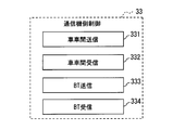
- the communicator-side control circuit 33 includes, as functional blocks, an inter-vehicle communication transmission control unit 331, an inter-vehicle communication reception control unit 332, a BT communication transmission control unit 333, and a BT communication reception.
- a control unit 334 is provided.
- the reception control unit for BT communication 334 receives the vehicle data transmitted from the mobile terminal 2 via the communication device side BT communication unit 31.
- the inter-vehicle communication transmission control unit 331 generates vehicle information of the main vehicle from the vehicle data received by the BT communication reception control unit 334 and transmits the vehicle information via the inter-vehicle communication unit 32.
- the inter-vehicle communication reception control unit 332 receives the vehicle information of the peripheral vehicle transmitted from the communication device 3 of the peripheral vehicle via the inter-vehicle communication unit 32.
- the BT communication transmission control unit 333 transmits the vehicle information received by the inter-vehicle communication reception control unit 332 to the mobile terminal 2 of the main vehicle via the communication device side BT communication unit 31.
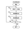
- vehicle information transmission related processing when the main vehicle information is transmitted to surrounding vehicles in the communication device side control circuit 33 of the communication device 3.
- each section is expressed as S10, for example.
- each section can be divided into a plurality of subsections, while a plurality of sections can be combined into one section.
- each section configured in this manner can be referred to as a device, module, or means.
- each of the above sections or a combination thereof includes (ii) not only a section of software combined with a hardware unit (eg, a computer) but also (ii) hardware. It can be implemented as a section of wear (e.g., integrated circuit, wiring logic circuit) with or without associated device functionality.
- the hardware section can be configured inside the microcomputer.
- the flowchart of FIG. 6 may be configured to start when the power of the communication device 3 and the portable terminal 2 is turned on.
- the reception control unit 334 for BT communication performs vehicle data reception processing, and proceeds to S12.
- the vehicle data acquisition request is transmitted to the portable terminal 2 via the communication device side BT communication unit 31, and the vehicle data returned from the portable terminal 2 in response to the acquisition request is The data is received via the communication device side BT communication unit 31.
- the communication device 3 transmits a vehicle data acquisition request to the portable terminal 2, and the BT communication reception control unit 334 receives vehicle data returned in response to the acquisition request.
- the latest vehicle data stored in the internal memory 282 may be transmitted from the portable terminal 2 at regular intervals, and the received vehicle data may be sequentially received by the BT communication reception control unit 334. .
- the vehicle-to-vehicle communication transmission control unit 331 performs vehicle information generation processing, and proceeds to S14.
- the vehicle information generation process of S12 an identification number for identifying the vehicle is given to the vehicle data received by the reception control unit 334 for BT communication, and vehicle information for transmission by inter-vehicle communication is generated.
- the device ID assigned uniquely to the communication device 3 is used as the identification number, but is not limited thereto.
- a vehicle ID assigned to each vehicle or a mobile terminal ID (for example, a manufacturing number) assigned to the mobile terminal 2 can be used.
- generated vehicle data and the transmission control part 331 for vehicle-to-vehicle communication showed the structure which implements the process which provides apparatus ID to the main vehicle information, it did not necessarily show to this. Not exclusively.
- the vehicle-to-vehicle communication transmission control unit 331 receives the sensor values of various sensors provided in the mobile terminal 2, and the vehicle-to-vehicle communication transmission control unit 331 generates main vehicle information based on the sensor values. Also good.
- the communication device 3 includes at least a satellite positioning system receiver such as the GPS receiver 24, main vehicle information is generated from the position of the communication device 3 of the main vehicle that can be detected using this receiver. It is good also as a structure.
- the azimuth angle of the main vehicle may be calculated from the position of the communication device 3 of the main vehicle by using a method similar to the above-described method of calculating from the time series data of the main vehicle position. Furthermore, when the communication device 3 is connected to a yaw rate sensor or a vehicle speed sensor (both not shown) included in the main vehicle by a CAN bus or the like, and if the sensor values of these various sensors can be obtained, Vehicle information may be generated based on the sensor value.
- the vehicle-to-vehicle communication transmission control unit 331 performs vehicle information transmission processing, and proceeds to S16.
- the vehicle information transmission process of S14 the vehicle information of the main vehicle generated in the vehicle information generation process is transmitted to surrounding vehicles via the inter-vehicle communication unit 32. Transmission of vehicle information shall be performed according to the transmission period of the vehicle-to-vehicle communication in the communication apparatus 3, such as every 100 msec.
- S16 YES If it is the end timing of the vehicle information transmission related processing in S16 (S16 YES), the flow is ended. On the other hand, when it is not the end timing of the vehicle information transmission related process (NO in S16), the process returns to S10 and the flow is repeated.
- An example of the end timing of the vehicle information transmission related process is when at least one of the power of the communication device 3 and the portable terminal 2 is turned off.
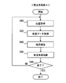
- the flowchart of FIG. 7 may be configured to start when the communication device 3 and the portable terminal 2 are turned on, as in the vehicle information transmission related process of FIG.
- the vehicle-to-vehicle communication reception control unit 332 performs vehicle information reception processing, and proceeds to S22.
- the vehicle information reception process of S20 the vehicle information transmitted by the surrounding vehicle via the inter-vehicle communication unit 32 is received.
- the vehicle information of surrounding vehicles shall be received sequentially.
- the transmission control unit 333 for BT communication performs a transfer process and proceeds to S24.
- vehicle information of surrounding vehicles is transmitted to the portable terminal 2 via the communication device side BT communication unit 31.
- vehicle information received by S20 shall be sequentially transferred to the portable terminal 2 by performing S22 sequentially, it is not restricted to this.
- a fixed transfer cycle (100 milliseconds) may be set, and vehicle information of surrounding vehicles received during that time may be transferred collectively.
- S24 YES If it is the end timing of the vehicle information reception related process in S24 (S24 YES), the flow ends. On the other hand, when it is not the end timing of the vehicle information reception related process (NO in S24), the process returns to S20 and the flow is repeated.
- An example of the end timing of the vehicle information reception related process is when the power of at least one of the communication device 3 or the portable terminal 2 is turned off.
- dangerous vehicle determination processing for determining whether or not the surrounding vehicle is a dangerous vehicle in the dangerous vehicle determination unit 286 will be described using the flowchart shown in FIG.
- the flowchart of FIG. 8 is executed for each surrounding vehicle when, for example, the vehicle information of the surrounding vehicle is received.
- the surrounding vehicle that is the target of the dangerous vehicle determination process is referred to as a target vehicle or a target other vehicle in order to distinguish it from other surrounding vehicles.
- this threshold value Ath may be another value (for example, 0.5 G), and a value obtained by determining the acceleration of the vehicle determined to be dangerous from past observation data may be used.
- a different threshold Ath may be set for each vehicle type. For example, 0.6G for passenger cars, 0.7G for vans, 0.5G for trucks less than 4t, 0.45G for trucks and buses of 4t to 10t and less. Of course, these values may be appropriately designed values.
- S30 becomes YES and the process moves to S34.
- S30 is NO and the process proceeds to S31.
- the traveling speed of the target vehicle is greater than a predetermined threshold value Vth.
- the threshold value Vth may be, for example, the legal speed of the road on which the target vehicle is traveling.
- the legal speed of the road on which the target vehicle is traveling may be determined based on the type of road on which the target vehicle is traveling from map data stored in the memory 26.
- S31 when the traveling speed of the target vehicle is higher than Vth, S31 becomes YES and the process proceeds to S34.
- S31 is NO and the process proceeds to S32.
- a predetermined threshold value is added to the average value (average traveling speed or average speed) of the traveling speeds of other surrounding vehicles that travel around the target vehicle (mainly front and rear). It is determined whether or not the value is greater than the specified value.
- the threshold value Wth is 10 km / h as an example, but may be a value such as 5 km / h, or may be a value determined according to the average speed (20% of the average speed).
- the vehicle has an azimuth angle.
- the range in the front-rear direction of the target vehicle is not limited to 50 m, and may be other values, for example, a distance proportional to the traveling speed of the target vehicle.
- the azimuth angle condition has been made in view of the following concerns. For example, at an intersection or the like, there are a mixture of vehicles that are stopped and vehicles that are traveling, so if the average speed is calculated using all these vehicles as a population, it becomes an inappropriate value.
- the azimuth difference between the vehicle forming the population for calculating the average speed and the target vehicle is set to 10 degrees or less. Of course, other values (for example, 5 degrees) may be used. .
- the above-described front-rear direction is not limited to the front and back, but includes a range including diagonally forward and diagonally rear, but is not limited thereto.
- the vehicle that makes the population for calculating the average speed is a vehicle that travels in the same lane as the target vehicle, so that the average speed can be calculated with higher accuracy. This is because even if the road is the same, the speed of the flow of the vehicle may be different if the lane is different.
- traveling lanes are equal or not is calculated from a vehicle position and azimuth angle of the target vehicle by calculating a straight line extending the target vehicle in the longitudinal direction of the target vehicle, and the shortest distance from the surrounding vehicle of the target vehicle to the straight line is within 1 m. In some cases, it may be determined that the traveling lanes are equal. Moreover, you may determine whether the driving
- S32 when the traveling speed of the target vehicle is larger than the value obtained by adding a predetermined threshold (Wth) to the average speed of the vehicle traveling around the target vehicle, S32 becomes YES and the process proceeds to S34.
- Wth predetermined threshold
- S32 when the traveling speed of the target vehicle is equal to or less than the value obtained by adding a predetermined threshold (Wth) to the average speed of the vehicles traveling around the target vehicle, S32 is NO and the process proceeds to S33. If there is no suitable vehicle around the target vehicle and the average speed cannot be calculated, S32 is NO and the process proceeds to S33.
- the threshold Yth is 0.07 rad / sec ( ⁇ 4 deg / sec), but may be other values, and is a value obtained from past observation data of the azimuth velocity of the vehicle determined to be dangerous. May be used.
- S33 when the azimuth velocity of the target vehicle is larger than the threshold value Yth, S33 becomes YES and proceeds to S34.
- S33 is NO and the process proceeds to S35.
- the dangerous vehicle determination unit 286 stores, in the internal memory 282, the identification ID of the surrounding vehicle determined as the dangerous vehicle, separately from the identification ID of the normal vehicle so that it can be recognized as a dangerous vehicle.
- the dangerous vehicle determination unit 286 stores the identification ID of the surrounding vehicle determined as a normal vehicle in the internal memory 282 so that it can be recognized as a normal vehicle.
- peripheral vehicle display-related processes for displaying information on the surrounding vehicles (positions of the surrounding vehicles, whether or not the vehicle is dangerous, etc.) on the display 27.
- This flowchart is started when, for example, the power of the communication device 3 and the portable terminal 2 is turned on.
- a position acquisition process is performed, and the process proceeds to S42.
- the map image drawing unit 287 reads the main vehicle position information stored in the internal memory 282 with the latest time stamp (that is, the latest main vehicle position information).
- the map image drawing unit 287 performs map data acquisition processing, and proceeds to S44.
- map data acquisition process of S41 map data near the current main vehicle position is read from the memory 26.
- the range of the map data read from the memory 26 is determined by the current position of the main vehicle and the display scale of the map image.
- the map image drawing unit 287 performs the map image drawing process and proceeds to S46.
- a map image is generated from the map data read in S41 so that the current main vehicle position is arranged near the center of the screen.
- the surrounding vehicle display unit 288 performs the surrounding vehicle drawing process and proceeds to S48.
- the surrounding vehicle drawing process of S46 the surrounding vehicle display unit 288 superimposes the mark representing the position and azimuth of the surrounding vehicle identified for each vehicle by the vehicle identifying unit 285 on the map image generated in S46. And draw.
- the vehicle is displayed with a mark having a different display mode such as a color and a shape from the mark of the normal vehicle.
- A represents the main vehicle
- B1 to B6 represent surrounding vehicles for the main vehicle.
- Each of A and B1 to B6 includes the dangerous vehicle notification device 1, and all of them are in a range where wireless communication can be performed by the communication device 3.
- B1 to B4 are normal vehicles
- B5 and B6 are dangerous vehicles.
- the normal vehicles B1 to B4 are represented by isosceles triangles as shown in FIG. 11, and each vehicle travels in the direction of the apex of the isosceles triangle. That is, the direction of the isosceles triangle represents the azimuth angle of the vehicle.
- the marks indicating these normal vehicles B1 to B4 are displayed in gray, for example.
- the main vehicle A is arranged near the center of the screen (slightly below the center) and is displayed with a mark different from that of the normal vehicle and the dangerous vehicle so that it can be distinguished from the surrounding vehicles.
- the main vehicle may be displayed in blue.
- the dangerous vehicles B5 and B6 are displayed as isosceles triangles painted in, for example, yellow, orange, red, etc. so that it can be understood at a glance that they are dangerous vehicles. Further, an exclamation mark or the like may be displayed inside.
- an isosceles triangle is used as a mark indicating the position and azimuth of each vehicle, but other figures such as arrows may be used.
- the driver of the main vehicle A can recognize at a glance whether or not the surrounding vehicle is a dangerous driving vehicle. For example, when the surrounding vehicle running in front of the main vehicle is a dangerous vehicle, it is possible to take measures such as making the inter-vehicle distance longer than usual, and further safe driving can be attempted. Become.
- the operation and effect in the present embodiment are as follows. First, according to the above configuration, whether or not the other vehicle is a dangerous driving vehicle (that is, a dangerous vehicle) is determined based on the other vehicle determination information transmitted by the other vehicle. However, the dangerous vehicle is displayed in a display mode different from other vehicles that are not dangerous vehicles. The driver of the main vehicle can recognize whether or not the other vehicle traveling around the vehicle is a dangerous driving vehicle by looking at the display. Therefore, it is possible to notify the driver of the main vehicle whether or not the surrounding vehicle is driving dangerously.
- a dangerous driving vehicle that is, a dangerous vehicle
- the present embodiment it is configured such that whether the surrounding vehicle is a dangerous vehicle is determined by the main vehicle on the receiving side.
- a configuration is also conceivable in which, in the surrounding vehicle on the transmission side, it is determined whether or not the surrounding vehicle itself is a dangerous vehicle and the determination result is transmitted to the main vehicle.
- the determination criteria for determining the dangerous vehicle that is, the above-described various threshold values
- the reliability with respect to the determination result transmitted by the surrounding vehicle is lowered.
- whether or not the surrounding vehicle is a dangerous vehicle is determined by the main vehicle on the receiving side, thereby improving the reliability of whether or not the vehicle is a dangerous vehicle. it can. Further, if the driver of the main vehicle can set various threshold values (Ath, Vth, Wth, and Yth) used for determining whether or not the other vehicle is driving dangerously, the driver's preference A dangerous vehicle can be determined accordingly.
- the communication area since the area that can be used for vehicle-to-vehicle communication is limited, when the determination result is separately transmitted in addition to the vehicle information such as acceleration, the communication area may be insufficient. However, regarding vehicle information such as acceleration, since an area used in inter-vehicle communication has already been secured, there is no fear of lack of a communication area. Therefore, as in this embodiment, the surrounding vehicle transmits vehicle information of the vehicle and determines whether or not the main vehicle on the receiving side is a dangerous vehicle, thereby making the communication area more efficient. The present embodiment can be implemented more smoothly.
- the traveling speed of the target vehicle is compared with the average value (average speed) of the traveling speeds of other surrounding vehicles that travel around the target vehicle.
- the present invention is not limited to this. Whether or not the vehicle is a dangerous vehicle may be determined based on other statistical criteria. For example, in a normal distribution in which the traveling speed of other surrounding vehicles traveling around the target vehicle is a population, when the traveling speed of the target vehicle falls outside the range of minus 1 ⁇ to plus 1 ⁇ , It is good also as a structure to determine.
- the surrounding vehicles are distinguished in two stages, that is, a normal vehicle and a dangerous vehicle, but the present invention is not limited to this.
- a surrounding vehicle that exceeds 10 km / h and a surrounding vehicle that exceeds 30 km / h with respect to a threshold value Vth for determining whether or not the vehicle is performing dangerous driving based on the traveling speed may be a dangerous vehicle.
- the travel speed threshold Vth may be further divided into a plurality of stages, and the degree of danger may be evaluated in a plurality of stages.
- the dangerous vehicle display unit 288A displays in different display modes depending on the danger level of the surrounding vehicle. For example, the higher the degree of danger, the more the display mode is conspicuous for the driver of the main vehicle, such as the red color or blinking at a faster cycle, and the closer the degree of danger, the closer to the normal vehicle. Furthermore, the danger level of the dangerous vehicle may be reduced with the passage of time, and the surrounding vehicle display unit 288 may bring the display mode closer to the mark of the normal vehicle in accordance with the danger level.
- the configuration is described in which the degree of danger is evaluated in a plurality of stages by taking the traveling speed as an example. However, for other accelerations and azimuth angular velocities, similarly, the degree of danger is evaluated using a threshold of a plurality of stages. May be.
- the dangerous vehicle determination unit 286 may determine whether or not the main vehicle itself is a dangerous vehicle from the vehicle information of the main vehicle. Accordingly, the dangerous vehicle display unit 288A displays a display mode of an icon indicating the main vehicle so that it can be recognized that the vehicle is a dangerous vehicle. As a result, the driver of the main vehicle himself / herself can be made aware of how it is viewed from the surrounding vehicles, and the driver of the main vehicle can be encouraged to try safe driving.
- the dangerous vehicle determination unit 286 may determine whether or not the surrounding vehicle (simply a target vehicle) is meandering from the time-series data of the azimuth angular velocity and the direction change of the surrounding vehicle. Whether or not the meandering operation is performed may be determined as the meandering operation when, for example, the azimuth velocity (or azimuth angle) vibrates in a certain width or more within a certain time and the vibrations exceed a certain width.
- the dangerous vehicle display unit 288A may display in a display mode different from that of the normal vehicle and other dangerous vehicles.
- the map data is stored in the memory 26.
- the present invention is not limited to this.
- the mobile terminal 2 can use a mobile phone line or the like, a configuration may be adopted in which necessary map data is acquired by accessing an external server (not shown).
- the program 4 may also be stored on an external server.
Abstract
On the basis of other vehicle determination information transmitted by each of a plurality of other vehicles (B), a reckless vehicle determination unit (286) of a vehicle (A) determines whether each of the other vehicles is a recklessly driving vehicle. A target other vehicle determined to be a recklessly driving vehicle is displayed on a display (27) in a different display mode from other vehicles determined to be not recklessly driving.
Description
本開示は、2013年4月9日に出願された日本出願番号2013-81530号に基づくもので、ここにその記載内容を援用する。
This disclosure is based on Japanese Patent Application No. 2013-81530 filed on April 9, 2013, the contents of which are incorporated herein by reference.
本開示は、車々間通信を利用して、車両の周囲に存在する他の危険車両を運転者に通知する技術に関する。
This disclosure relates to a technique for notifying a driver of other dangerous vehicles existing around a vehicle using inter-vehicle communication.
従来、特許文献1に開示されているように、車々間通信を利用して取得した、車両の周辺に存在する車両(すなわち周辺車両)の位置や進行方向を、地図画像に重畳させて表示する技術がある。
2. Description of the Related Art Conventionally, as disclosed in Patent Document 1, a technique for displaying the position and traveling direction of a vehicle (that is, a surrounding vehicle) existing around a vehicle, acquired by using inter-vehicle communication, superimposed on a map image. There is.
しかし、特許文献1に開示の技術のように、周辺車両の位置や進行方向を表示するだけでは、その周辺車両を運転するドライバが安全運転しているのか、危険運転しているのかが不明であった。運転者としては、周辺車両が危険運転をしていることを知ることが出来れば、車間距離を標準よりも長めにとるなどの対策をとることができるようになる。
However, as with the technique disclosed in Patent Document 1, it is unclear whether the driver driving the surrounding vehicle is driving safely or driving dangerously only by displaying the position and traveling direction of the surrounding vehicle. there were. As a driver, if it is possible to know that the surrounding vehicle is driving dangerously, it is possible to take measures such as making the inter-vehicle distance longer than the standard distance.
本開示の目的とするところは、周辺車両が危険運転しているか否かを車両のドライバへ通知することが可能になる危険車両通知装置、危険車両通知プログラム製品、危険車両通知方法を提供することにある。
An object of the present disclosure is to provide a dangerous vehicle notification device, a dangerous vehicle notification program product, and a dangerous vehicle notification method capable of notifying a driver of a vehicle whether or not a surrounding vehicle is driving dangerously. It is in.
その目的を達成するための本開示の第1の例によれば、危険車両通知装置は次のように提供される。危険車両通知装置は、車両に搭載され、この車両とは異なる複数の他車両の各々に搭載されるところの、機能において同一である他危険車両通知装置と、無線通信を介してデータを送受信する。更に、危険車両通知装置は、前記車両の位置を検出する位置検出部と、前記車両の位置を示す位置データを送信するとともに、前記各他車両が送信した、前記各他車両の位置を示す位置データを受信する車載通信機とを備える。さらに、危険車両通知装置は、(i)前記車載通信機で受信した前記各他車両の位置データに基づいて前記各他車両の位置を示すマークをディスプレイに表示するマーク表示処理部、(ii)前記車両にて危険運転をしているか否かを判定するために用いられる判定用情報を取得する判定用情報取得部、(iii)前記判定用情報取得部が取得した前記判定用情報を、前記車載通信機を介して送信する送信制御部、(iv)前記各他車両が送信した、前記各他車両についての危険運転をしているか否かを判定するために用いられる判定用情報を、前記車載通信機を介して受信する受信制御部、(v)前記受信制御部で受信した前記各他車両の判定用情報から前記各他車両が危険運転をしているか否かを判定する危険車両判定部とを備える。さらに、危険車両通知装置は、前記危険車両判定部で危険運転をしていると判定された前記他車両であるところのターゲット他車両の位置を示す前記マークを、危険運転をしていると判定されていない各他車両の位置を示す前記マークを表示する第2表示モードとは異なる第1表示モードで表示する危険車両表示処理部とを備える。
According to the first example of the present disclosure for achieving the object, the dangerous vehicle notification device is provided as follows. The dangerous vehicle notification device is mounted on a vehicle and transmits / receives data via wireless communication to / from another dangerous vehicle notification device that is mounted on each of a plurality of other vehicles different from the vehicle and has the same function. . Furthermore, the dangerous vehicle notification device transmits a position detection unit that detects the position of the vehicle, position data indicating the position of the vehicle, and a position indicating the position of each other vehicle transmitted by each other vehicle. And an in-vehicle communication device for receiving data. Further, the dangerous vehicle notification device is (i) a mark display processing unit that displays on the display a mark indicating the position of each other vehicle based on the position data of each other vehicle received by the in-vehicle communication device, (ii) A determination information acquisition unit for acquiring determination information used to determine whether or not the vehicle is driving dangerously; (iii) the determination information acquired by the determination information acquisition unit; A transmission control unit that transmits via an in-vehicle communication device, (iv) the information for determination used to determine whether or not each other vehicle transmits a dangerous driving for each other vehicle, A reception control unit that receives via an in-vehicle communication device; (v) a dangerous vehicle determination that determines whether or not each other vehicle is driving dangerously from the determination information of each other vehicle received by the reception control unit; A part. Furthermore, the dangerous vehicle notification device determines that the mark indicating the position of the target other vehicle that is the other vehicle determined to be dangerously driven by the dangerous vehicle determination unit is dangerously driven. A dangerous vehicle display processing unit for displaying in a first display mode different from the second display mode for displaying the mark indicating the position of each other vehicle that has not been provided.
以上の構成では、車両に搭載された危険車両通知装置の危険車両判定部は、他車両が送信する当該他車両の判定用情報に基づいて、当該他車両が危険運転をしている車両であるか否かを判定する。そして、危険運転をしている車両であると判定したターゲット他車両は、他の危険運転をしていないと判定されている他車両とは異なる表示モード(表示形式ともいえる)でディスプレイに表示される。車両のドライバは、ディスプレイを見ることで周囲を走行する他車両が、危険運転をしている車両であるか否かを認識することができる。したがって、以上の構成によれば、周辺車両が危険運転しているか否かを車両のドライバへ通知することが可能になる。
In the above configuration, the dangerous vehicle determination unit of the dangerous vehicle notification device mounted on the vehicle is a vehicle in which the other vehicle is performing dangerous driving based on the determination information of the other vehicle transmitted by the other vehicle. It is determined whether or not. Then, the target other vehicle determined to be a vehicle that is driving dangerously is displayed on the display in a display mode (also referred to as a display format) that is different from that of the other vehicle that is determined not to perform other dangerous driving. The The driver of the vehicle can recognize whether or not the other vehicle traveling around the vehicle is a dangerous driving vehicle by looking at the display. Therefore, according to the above configuration, it is possible to notify the driver of the vehicle whether or not the surrounding vehicle is driving dangerously.
また、本開示の第2の例によれば、危険車両通知プログラム製品は、次のように提供される。即ち、コンピュータを、前記第1の例の危険車両通知装置に含まれるところの、前記判定用情報取得部、前記送信制御部、前記受信制御部、前記マーク表示処理部、前記危険車両判定部、および前記危険車両表示処理部として機能させるインストラクションを含み、コンピュータ読取可能な非遷移の記憶媒体に記録された危険車両通知プログラム製品として提供される。
Also, according to the second example of the present disclosure, the dangerous vehicle notification program product is provided as follows. That is, the computer is included in the dangerous vehicle notification device of the first example, the determination information acquisition unit, the transmission control unit, the reception control unit, the mark display processing unit, the dangerous vehicle determination unit, And a dangerous vehicle notification program product recorded in a computer-readable non-transition storage medium, including instructions for functioning as the dangerous vehicle display processing unit.
さらに、本開示の第3の例によれば、危険車両通知プログラム製品は、次のように提供される。即ち、コンピュータによって実行され、前記第1の例の危険車両通知装置に含まれるところの、前記判定用情報取得部、前記送信制御部、前記受信制御部、前記マーク表示処理部、前記危険車両判定部、および前記危険車両表示処理部として機能を実現するための危険車両通知方法として提供される。
Furthermore, according to the third example of the present disclosure, the dangerous vehicle notification program product is provided as follows. That is, the determination information acquisition unit, the transmission control unit, the reception control unit, the mark display processing unit, and the dangerous vehicle determination, which are executed by a computer and included in the dangerous vehicle notification device of the first example. And a dangerous vehicle notification method for realizing the function as the dangerous vehicle display processing unit.
本開示についての上記目的およびその他の目的、特徴や利点は、添付の図面を参照しながら下記の詳細な記述により、より明確になる。
本開示の実施形態に係る危険車両通知装置を適用した危険車両通知システムの概略的な構成を示す図であり、
危険車両通知装置の概略的な構成の一例を示す図であり、
本実施形態における携帯側制御回路の概略的な構成の一例を示す機能ブロック図であり、
車両データ算出部の概略的な構成の一例を示す機能ブロック図であり、
本実施形態における通信機側制御回路の概略的な構成の一例を示す機能ブロック図であり、
車両情報送信関連処理の流れを示すフローチャートであり、
車両情報受信関連処理の流れを示すフローチャートであり、
危険車両判定処理の流れを示すフローチャートであり、
周辺車両表示関連処理の流れを示すフローチャートであり、
ディスプレイの表示画面の一例である。
The above and other objects, features and advantages of the present disclosure will become more apparent from the following detailed description with reference to the accompanying drawings.
It is a diagram showing a schematic configuration of a dangerous vehicle notification system to which a dangerous vehicle notification device according to an embodiment of the present disclosure is applied, It is a diagram showing an example of a schematic configuration of a dangerous vehicle notification device, It is a functional block diagram showing an example of a schematic configuration of a portable side control circuit in the present embodiment, It is a functional block diagram showing an example of a schematic configuration of a vehicle data calculation unit, It is a functional block diagram showing an example of a schematic configuration of a communication device side control circuit in the present embodiment, It is a flowchart showing a flow of vehicle information transmission related processing, It is a flowchart showing a flow of vehicle information reception related processing, It is a flowchart showing the flow of dangerous vehicle determination processing, It is a flowchart showing the flow of the surrounding vehicle display related processing, It is an example of the display screen of a display.
以下、本開示の実施形態を、図1~10を用いて説明する。図1は、本開示に係る危険車両通知装置1を適用した車車間通信システム(以降、危険車両通知システムとする)100の概略的な構成の一例を示す図である。この危険車両通知システム100は、複数の車両の各々で1つずつ用いられる危険車両通知装置1を備えている。複数の車両は、車両Aと、図1には図示されていないが、少なくとも2つ以上の複数の車両Bを含む。なお、車両Aは、主車両あるいは、単に車両と言及され、また、車両Bは他車両とも言及される。また、これらの主車両、他車両の関係は、相対的に定まるものであり、仮に一つの車両Bを主車両とすると、当然ながら車両Aは車両Bにとっての他車両となる。尚、ある装置を搭載する車両を引用する場合は、そのある装置についてのホスト車両とも言及される。
Hereinafter, embodiments of the present disclosure will be described with reference to FIGS. FIG. 1 is a diagram illustrating an example of a schematic configuration of a vehicle-to-vehicle communication system (hereinafter, referred to as a dangerous vehicle notification system) 100 to which a dangerous vehicle notification device 1 according to the present disclosure is applied. The dangerous vehicle notification system 100 includes a dangerous vehicle notification device 1 that is used one by one for each of a plurality of vehicles. The plurality of vehicles include a vehicle A and a plurality of vehicles B that are not shown in FIG. Vehicle A is referred to as a main vehicle or simply a vehicle, and vehicle B is also referred to as another vehicle. In addition, the relationship between these main vehicles and other vehicles is relatively determined. If one vehicle B is the main vehicle, the vehicle A naturally becomes another vehicle for the vehicle B. In addition, when quoting the vehicle carrying a certain apparatus, it is also referred to as the host vehicle for the certain apparatus.
ここで、図2を用いて、危険車両通知装置1の概略的な構成について説明を行う。図2は、危険車両通知装置1の概略的な構成の一例を示す図である。図2に示すように危険車両通知装置1は、携帯端末2及び通信機3を備えている。
Here, a schematic configuration of the dangerous vehicle notification device 1 will be described with reference to FIG. FIG. 2 is a diagram illustrating an example of a schematic configuration of the dangerous vehicle notification device 1. As shown in FIG. 2, the dangerous vehicle notification device 1 includes a mobile terminal 2 and a communication device 3.
携帯端末2は、これが搭載されているところの主車両の周辺に存在する他車両(以降、単に周辺車両)に送信するためのデータを取得するとともに、周辺車両から受信したデータを、ディスプレイ27を介して主車両のドライバに通知するためのデバイスである。なお、主車両の周辺とは、後述する通信機3が無線通信可能な範囲を意味する。携帯端末2としては、公知のスマートフォン等の多機能携帯電話機を利用する構成とすればよい。携帯端末2は、一例として、主車両のドライバが携帯端末2のディスプレイ27を視認できるように車室内に一時的に固定される。また、本実施形態では、より好ましい形態として、主車両に対する携帯端末2の取付姿勢(主車両の前後方向に対する携帯端末2の向きや、水平面に対する自端末の角度など)を予め携帯端末2に設定しておき、その設定に従った位置に取り付けられるものとする。例えば、ディスプレイ27が水平面に対して110度を為して運転者席の方に向き、かつ、携帯端末2の上下方向の水平面への写像成分と主車両の前後方向とが一致するように、設置する。もちろん、車両への携帯端末2への取付姿勢はこれに限らず、ドライバによって設定すれば良い。
The mobile terminal 2 obtains data to be transmitted to other vehicles (hereinafter simply referred to as surrounding vehicles) existing around the main vehicle where the mobile terminal 2 is mounted, and displays the data received from the surrounding vehicles on the display 27. It is a device for notifying the driver of the main vehicle via. In addition, the periphery of the main vehicle means a range in which the communication device 3 described later can perform wireless communication. The mobile terminal 2 may be configured to use a known multifunction mobile phone such as a smartphone. As an example, the mobile terminal 2 is temporarily fixed in the passenger compartment so that the driver of the main vehicle can visually recognize the display 27 of the mobile terminal 2. Moreover, in this embodiment, as a more preferable form, the mounting orientation of the mobile terminal 2 with respect to the main vehicle (the orientation of the mobile terminal 2 with respect to the front-rear direction of the main vehicle, the angle of the own terminal with respect to the horizontal plane, etc.) is set in the mobile terminal 2 in advance. In addition, it shall be attached to the position according to the setting. For example, the display 27 is directed to the driver's seat at 110 degrees with respect to the horizontal plane, and the mapping component to the horizontal plane in the vertical direction of the mobile terminal 2 matches the front-rear direction of the main vehicle. Install. Of course, the mounting posture of the mobile terminal 2 on the vehicle is not limited to this, and may be set by a driver.
また、携帯端末2は、上述したデバイスとしての機能を実現するために、携帯側Bluetooth(登録商標、以下BT)通信部21、検出部22、メモリ26、ディスプレイ27、及び携帯側制御回路28を備えている。
In addition, the mobile terminal 2 includes a mobile side Bluetooth (registered trademark, hereinafter referred to as BT) communication unit 21, a detection unit 22, a memory 26, a display 27, and a mobile side control circuit 28 in order to realize the above-described device function. I have.
携帯側BT通信部21は、送受信アンテナを備え、主車両の通信機3との間でBluetoothの規格に従った通信(以下、BT通信)を行うことで、情報のやり取りを行う。なお、本実施形態では、携帯端末2と通信機3との間での通信を、BT通信で行う構成を示したが、必ずしもこれに限らない。例えばZigBee(登録商標)等の近距離無線通信規格やIEEE802.11等の無線LAN規格などに従った無線通信によって行う構成としてもよいし、USB通信等の有線通信によって行う構成としてもよい。尚、携帯側BT通信部21は、別通信部あるいは付加通信部とも言及される。
The portable-side BT communication unit 21 includes a transmission / reception antenna and exchanges information with the communication device 3 of the main vehicle by performing communication according to the Bluetooth standard (hereinafter referred to as BT communication). In the present embodiment, the configuration in which the communication between the mobile terminal 2 and the communication device 3 is performed by BT communication is shown, but the configuration is not necessarily limited thereto. For example, it may be configured to perform wireless communication according to short-range wireless communication standards such as ZigBee (registered trademark) or wireless LAN standards such as IEEE 802.11, or may be configured to perform wired communication such as USB communication. The portable BT communication unit 21 is also referred to as a separate communication unit or an additional communication unit.
検出部22は、主車両の走行が安全運転であるか否かを判定するための情報を生成するための種々のデータを取得する。たとえば本実施形態においては、検出部22は、GPS(Global Positioning System)衛星からの電波を受信するGPS受信機221、自端末に作用する加速度を検出する加速度センサ222、自端末に作用する角速度や角度を検出するジャイロセンサ223、を備えている。
The detection unit 22 acquires various data for generating information for determining whether or not the driving of the main vehicle is a safe driving. For example, in the present embodiment, the detection unit 22 includes a GPS receiver 221 that receives radio waves from a GPS (Global Positioning System) satellite, an acceleration sensor 222 that detects acceleration acting on the terminal, an angular velocity acting on the terminal, A gyro sensor 223 for detecting an angle is provided.
メモリ26は、経路案内用の地図データ、および、公知の多機能携帯電話機などの携帯端末を本実施形態に係る携帯端末2として動作させるためのプログラム4を保存するための電気的に書き換え可能な不揮発性メモリである。メモリ26は、SDカード等の携帯端末2から取り外し可能な記憶媒体であってもよい。例えば、メモリ26は、ドライバによる操作によって消去の指示が行われない限り、保存したデータを消去しない構成とする。なお、公知の携帯端末を本実施形態に係る携帯端末2として動作させるためのプログラム4は、後述する携帯側制御回路28が備えるROMなどの記憶領域にインストールされていてもよい。このプログラム4は危険車両通知プログラム製品とも言及される。
The memory 26 is electrically rewritable for storing the map data for route guidance and the program 4 for operating a portable terminal such as a known multi-function mobile phone as the portable terminal 2 according to the present embodiment. It is a non-volatile memory. The memory 26 may be a storage medium that is removable from the portable terminal 2 such as an SD card. For example, the memory 26 is configured not to erase the stored data unless an instruction to erase is given by an operation by the driver. Note that the program 4 for causing a known mobile terminal to operate as the mobile terminal 2 according to the present embodiment may be installed in a storage area such as a ROM provided in the mobile-side control circuit 28 described later. This program 4 is also referred to as a dangerous vehicle notification program product.
ディスプレイ27は、携帯側制御回路28から入力される信号に基づいてテキストや画像を表示する。例えばディスプレイ27は、フルカラー表示が可能なものであって、TFT液晶ディスプレイ、有機ELディスプレイ等を用いて構成することができる。
The display 27 displays text and images based on signals input from the mobile control circuit 28. For example, the display 27 is capable of full-color display and can be configured using a TFT liquid crystal display, an organic EL display, or the like.
携帯側制御回路28は、通常のコンピュータとして構成されており、内部には周知のCPU、ROMやRAMやEEPROMなどのメモリ、I/O、及びこれらの構成を接続するバスライン(いずれも図示せず)などが備えられている。携帯側制御回路28は、携帯側BT通信部21、検出部22から入力された各種情報に基づき、ROMあるいはメモリ26に予め記憶されているプログラムをCPUが実行することによって各種の処理を実行する。また、携帯側制御回路28は、1つあるいは複数のIC等としてハードウエアの構成として実現してもよい。
The portable-side control circuit 28 is configured as a normal computer, and has a well-known CPU, memory such as ROM, RAM, and EEPROM, I / O, and a bus line for connecting these configurations (all not shown). Etc.). The portable side control circuit 28 executes various processes by the CPU executing programs stored in advance in the ROM or the memory 26 based on various information input from the portable side BT communication unit 21 and the detection unit 22. . The portable control circuit 28 may be realized as a hardware configuration as one or a plurality of ICs.
図3に示すように、携帯側制御回路28は、周辺車両へ送信するデータを処理するための機能ブロックとして、車両データ算出部281、内部メモリ282、および送信制御部283を備えている。また、周辺車両から受信したデータを処理するための機能ブロックとして、受信制御部284、車両識別部285、危険車両判定部286、地図画像描画部287、周辺車両表示部288、および危険判定継続部289を備えている。内部メモリ282は、例えばRAMやEEPROM等の電気的に書き換え可能なメモリに構築されるものとする。なお、ここでは、便宜上、一般的な多機能携帯電話機が有している機能に関する構成のうち、本開示の説明に不要なものについては説明を省略している。
As shown in FIG. 3, the portable side control circuit 28 includes a vehicle data calculation unit 281, an internal memory 282, and a transmission control unit 283 as functional blocks for processing data to be transmitted to surrounding vehicles. In addition, as a functional block for processing data received from surrounding vehicles, a reception control unit 284, a vehicle identification unit 285, a dangerous vehicle determination unit 286, a map image drawing unit 287, a surrounding vehicle display unit 288, and a risk determination continuation unit 289. It is assumed that the internal memory 282 is constructed in an electrically rewritable memory such as a RAM or an EEPROM. Here, for the sake of convenience, among the configurations related to the functions of a general multi-function mobile phone, those that are not necessary for the description of the present disclosure are omitted.
車両データ算出部281は、検出部22で逐次検出する種々のセンサデータから、主車両の走行状態に関する種々のデータ(車両データ)を算出し、内部メモリ282に格納する。車両データ算出部281で算出される車両データは、一例として、携帯端末2の位置(すなわち、主車両の位置)、主車両の走行速度、主車両に作用している加速度、主車両の進行方向(以降、方位角とする)、および方位角速度を含む。ただし、本実施形態を実施する上で、必ずしもこれらの全ての種類のデータが必要とは限らない。安全運転であるか否かを判定するために用いるデータを取得出来ればよく、これらうちの少なくとも1つを含んでいればよい。たとえば、車両データは、主車両の位置と加速度だけであってもよい。これらの車両データを取得するための機能ブロックとして、車両データ算出部281は、図4に示すように、自端末取付姿勢検出部281A、加速度算出部281B、速度算出部281C、方位角速度算出部281D、方位角算出部281E、および位置取得部281Fを備えている。なお、この車両データ算出部281は、判定用情報取得部としても機能するとも言え、一方、車両データは判定用情報とも言及される。
The vehicle data calculation unit 281 calculates various data (vehicle data) related to the traveling state of the main vehicle from various sensor data sequentially detected by the detection unit 22 and stores the data in the internal memory 282. The vehicle data calculated by the vehicle data calculation unit 281 includes, for example, the position of the mobile terminal 2 (that is, the position of the main vehicle), the traveling speed of the main vehicle, the acceleration acting on the main vehicle, and the traveling direction of the main vehicle. (Hereinafter referred to as azimuth angle) and azimuth velocity. However, not all of these types of data are necessarily required when implementing this embodiment. It is sufficient that data used for determining whether or not the vehicle is safe driving can be acquired, and it is sufficient that at least one of them is included. For example, the vehicle data may be only the position and acceleration of the main vehicle. As functional blocks for acquiring these vehicle data, the vehicle data calculation unit 281 includes, as shown in FIG. 4, an own terminal mounting posture detection unit 281A, an acceleration calculation unit 281B, a speed calculation unit 281C, and an azimuth angular velocity calculation unit 281D. , An azimuth angle calculation unit 281E, and a position acquisition unit 281F. The vehicle data calculation unit 281 can also be said to function as a determination information acquisition unit, while vehicle data is also referred to as determination information.
自端末取付姿勢検出部281Aは、主車両に対する携帯端末2の取付姿勢を検出する。本実施形態のように主車両に対する取付姿勢が予め設定されている場合は、その設定値を用いることとするが、これに限らない。たとえば、加速度センサ222およびジャイロセンサ223を備える携帯端末2であれば、これらのセンサデータから公知の技術によって、自端末の向きや、水平面に対する傾きを検出することができる。そして、後述する位置取得部281Fで算出される主車両の位置の時系列データから主車両の前後方向を検出し、その前後方向に対する自端末の向きを算出すればよい。たとえば主車両の前後方向は、位置取得部281Fで算出される主車両の位置の時系列データから直線道路を走行している区間を検出し、その直線区間を走行している際の移動方向を主車両の前後方向とすればよい。主車両に対する携帯端末2の取付姿勢を検出することで、たとえば自端末に作用する加速度などのセンサ値から、主車両の前後方向に作用する加速度を求めることできるようになる。
The own terminal mounting posture detection unit 281A detects the mounting posture of the mobile terminal 2 with respect to the main vehicle. When the mounting posture with respect to the main vehicle is set in advance as in the present embodiment, the set value is used, but the present invention is not limited to this. For example, if it is the portable terminal 2 provided with the acceleration sensor 222 and the gyro sensor 223, the direction of the own terminal and the inclination with respect to a horizontal surface can be detected from these sensor data by a known technique. Then, the front-rear direction of the main vehicle may be detected from the time-series data of the position of the main vehicle calculated by the position acquisition unit 281F, which will be described later, and the direction of the own terminal relative to the front-rear direction may be calculated. For example, the front-rear direction of the main vehicle is determined by detecting a section traveling on a straight road from the time-series data of the position of the main vehicle calculated by the position acquisition unit 281F, and indicating the moving direction when traveling on the straight section. What is necessary is just to set it as the front-back direction of a main vehicle. By detecting the mounting posture of the mobile terminal 2 with respect to the main vehicle, for example, acceleration acting in the front-rear direction of the main vehicle can be obtained from sensor values such as acceleration acting on the own terminal.
加速度算出部281Bは、自端末取付姿勢検出部281Aが検出した取付姿勢から、自端末に作用する加速度のうち、主車両の前後方向成分(これを以降、単に加速度とする)を逐次算出する。なお、加速度は進行方向に生じる加速度を正の値で表し、減速方向の加速度は負の値で表す。また、本実施形態では、自端末に作用する加速度のうちの主車両の前後方向成分のみを算出する構成としたが、同様に、自端末に作用する加速度のうちの車両幅方向成分を別途算出する構成としても良い。この加速度算出部281Bは加速度取得部とも言及できる。
The acceleration calculation unit 281B sequentially calculates the longitudinal component of the main vehicle (hereinafter simply referred to as acceleration) from the acceleration acting on the terminal from the mounting posture detected by the terminal mounting posture detection unit 281A. Note that the acceleration is expressed as a positive value in the traveling direction, and the acceleration in the deceleration direction is expressed as a negative value. In the present embodiment, only the longitudinal component of the main vehicle in the acceleration acting on the terminal is calculated. Similarly, the vehicle width direction component in the acceleration acting on the terminal is calculated separately. It is good also as composition to do. This acceleration calculation unit 281B can also be referred to as an acceleration acquisition unit.
速度算出部281Cは、加速度算出部281Bが算出した、車両前後方向の加速度を積分することで、主車両の走行速度を逐次算出する。この速度算出部281Cは走行速度取得部とも言及される。また、方位角速度算出部281Dは、自端末取付姿勢検出部281Aが検出した取付姿勢と、ジャイロセンサ223が検出した角速度変化から、主車両に作用する方位角速度(rad/sec)を逐次算出する。この方位角速度算出部281Dは方位角速度取得部とも言及される。方位角算出部281Eは、ジャイロセンサ223が検出した角速度を積分することで自端末の角度変化を算出し、さらに、自端末取付姿勢検出部281Aが検出した自端末の向きと主車両の向きの相対関係から、主車両の方位角(rad)を逐次算出する。
The speed calculation unit 281C sequentially calculates the traveling speed of the main vehicle by integrating the acceleration in the vehicle longitudinal direction calculated by the acceleration calculation unit 281B. The speed calculation unit 281C is also referred to as a travel speed acquisition unit. Further, the azimuth angular velocity calculation unit 281D sequentially calculates the azimuth angular velocity (rad / sec) acting on the main vehicle from the mounting posture detected by the own terminal mounting posture detection unit 281A and the angular velocity change detected by the gyro sensor 223. This azimuth angular velocity calculation unit 281D is also referred to as an azimuth angular velocity acquisition unit. The azimuth angle calculation unit 281E calculates the angle change of the own terminal by integrating the angular velocity detected by the gyro sensor 223, and further, the direction of the own terminal and the direction of the main vehicle detected by the own terminal mounting posture detection unit 281A. From the relative relationship, the azimuth angle (rad) of the main vehicle is sequentially calculated.
位置取得部281Fは、GPS受信機221が受信する主車両の位置の情報に加えて、加速度センサ222およびジャイロセンサ223といった各センサから得られる情報をもとに、主車両の位置の検出を逐次行う。これらのセンサは、各々が性質の異なる誤差を持っているため、複数のセンサにより各々補完しながら主車両の位置の検出するように構成されているが、各センサの精度によっては上述した内の一部で構成してもよいし、上述した以外のセンサを用いる構成としてもよい。すなわち、位置取得部281Fは、GPS受信機24のみを用いて主車両の位置を検出する構成であっても良い。なお、主車両の位置は緯度および経度で表す。
The position acquisition unit 281F sequentially detects the position of the main vehicle based on information obtained from each sensor such as the acceleration sensor 222 and the gyro sensor 223 in addition to the information on the position of the main vehicle received by the GPS receiver 221. Do. Since these sensors have errors of different properties, they are configured to detect the position of the main vehicle while being complemented by a plurality of sensors, but depending on the accuracy of each sensor, It may be configured in part, or may be configured using a sensor other than those described above. That is, the position acquisition unit 281F may be configured to detect the position of the main vehicle using only the GPS receiver 24. The position of the main vehicle is represented by latitude and longitude.
なお、以上の加速度などの値を算出する方法は、上述したものに限定しない。たとえば速度算出部281Cは、時系列に並んだ複数の主車両の位置から、単位時間あたりの移動距離を算出することで、走行速度を算出すればよい。また、加速度算出部Bは、逐次算出する走行速度の時間微分した値を加速度として扱うことができる。
Note that the method for calculating the above acceleration and the like is not limited to the above. For example, the speed calculation unit 281C may calculate the travel speed by calculating the movement distance per unit time from the positions of a plurality of main vehicles arranged in time series. Moreover, the acceleration calculation part B can handle the value which carried out the time differentiation of the running speed calculated sequentially as an acceleration.
方位角算出部281Eは、たとえば、時系列に並んだ複数の位置から最小二乗法で求めた近似線が伸びる方向を算出して求めればよい。また、携帯端末2が地磁気センサを備えており、この地磁気センサの検出結果を利用可能な場合には、この地磁気センサの検出結果を利用して主車両の方位角を求める構成とすればよい。方位角速度算出部281Dは、方位角算出部281Eが逐次算出する方位角を時間微分して求めてよい。
The azimuth angle calculation unit 281E may calculate and calculate the direction in which the approximate line obtained by the least square method extends from a plurality of positions arranged in time series, for example. Moreover, what is necessary is just to set it as the structure which calculates | requires the azimuth | direction angle of a main vehicle using the detection result of this geomagnetic sensor, when the portable terminal 2 is provided with the geomagnetic sensor and the detection result of this geomagnetic sensor can be utilized. The azimuth velocity calculation unit 281D may obtain the azimuth angle sequentially calculated by the azimuth calculation unit 281E by performing time differentiation.
以上で車両データ算出部281が算出した車両データは、その算出した時刻の情報(つまり、タイムスタンプ)を付与して、内部メモリ282に格納される。内部メモリ282に新たなデータが格納される際に、割り当てられたメモリ容量を超える場合には、内部メモリ282に格納されているデータのうちで、より古い情報から順に消去していく構成とすればよい。もちろん、その他、記憶してから一定時間経過した車両データを消去する構成としてもよい。
The vehicle data calculated by the vehicle data calculation unit 281 as described above is stored in the internal memory 282 with information on the calculated time (that is, a time stamp). When new data is stored in the internal memory 282, if the allocated memory capacity is exceeded, the data stored in the internal memory 282 is erased in order from the oldest information. That's fine. Of course, other vehicle data that has been stored for a certain period of time may be deleted.
送信制御部283は、内部メモリ282に格納されている車両データを、携帯側BT通信部21を介して通信機3に送信するための制御を実施する。例えば送信制御部283は、主車両の通信機3から携帯側BT通信部21を介して主車両情報の取得要求を受けた場合に、内部メモリ282に蓄積されている車両データを読み出す。そして、読み出した車両データを、携帯側BT通信部21を介して通信機3に送信する。なお、読み出すデータは、最新のもの(すなわちタイムスタンプが最も新しいもの)だけとするが、そのほか、最新のものから複数時点分の過去の車両データを読み出して送信する構成であってもよい。なお、詳細は後述するが、車車間通信用送信制御部331において車両データは、車両を識別するための識別IDを付与された車両情報として周辺車両に送信される。
The transmission control unit 283 performs control for transmitting the vehicle data stored in the internal memory 282 to the communication device 3 via the portable BT communication unit 21. For example, the transmission control unit 283 reads the vehicle data stored in the internal memory 282 when receiving an acquisition request for main vehicle information from the communication device 3 of the main vehicle via the portable BT communication unit 21. Then, the read vehicle data is transmitted to the communication device 3 via the portable-side BT communication unit 21. Note that the data to be read is only the latest data (that is, the latest time stamp), but other past vehicle data for a plurality of time points may be read and transmitted from the latest data. Although details will be described later, in the inter-vehicle communication transmission control unit 331, the vehicle data is transmitted to surrounding vehicles as vehicle information to which an identification ID for identifying the vehicle is assigned.
受信制御部284は、主車両の通信機3が周辺車両から受信した周辺車両の車両情報を、携帯側BT通信部21を介して受信する。なお、周辺車両の車両情報は、主車両の車両情報と同様に、識別ID、車両位置、方位角、走行速度、加速度、および方位角速度などを含んでいる。
The reception control unit 284 receives the vehicle information of the surrounding vehicle received from the surrounding vehicle by the communication device 3 of the main vehicle via the portable side BT communication unit 21. Note that the vehicle information of the surrounding vehicles includes an identification ID, a vehicle position, an azimuth angle, a traveling speed, an acceleration, an azimuth angular velocity, and the like, similarly to the vehicle information of the main vehicle.
車両識別部285は、周辺車両の車両情報に含まれている識別IDから、同一車両から送信されたものであるか、異なる車両から送信されたものであるかを識別する。そして、車両ごとに車両情報を分別して、内部メモリ282に格納する。
The vehicle identification unit 285 identifies whether the vehicle ID is transmitted from the same vehicle or from a different vehicle, based on the identification ID included in the vehicle information of the surrounding vehicle. Then, the vehicle information is classified for each vehicle and stored in the internal memory 282.
危険車両判定部286は、周辺車両の車両情報から、周辺車両ごとに、危険運転をしている車両(以降、危険車両とする)であるか否かを判定する。周辺車両が危険車両であるか否かを判定する処理についての詳細は、後述する。
The dangerous vehicle determination unit 286 determines, based on the vehicle information of the surrounding vehicles, whether the vehicle is in a dangerous driving (hereinafter referred to as a dangerous vehicle) for each surrounding vehicle. Details of the process for determining whether or not the surrounding vehicle is a dangerous vehicle will be described later.
地図画像描画部287は、メモリ26から、現在の主車両位置付近の地図データを読み出し、主車両が画面の中心付近に表示されるように地図画像を描画する。メモリ26から読み出してくる地図データの範囲は、現在の主車両位置と、設定されている地図画像の表示縮尺によって決定される。
The map image drawing unit 287 reads the map data near the current main vehicle position from the memory 26 and draws the map image so that the main vehicle is displayed near the center of the screen. The range of the map data read from the memory 26 is determined by the current main vehicle position and the set display scale of the map image.
周辺車両表示部288は、地図画像描画部287が描画した地図画像に、車両識別部285で車両毎に識別された周辺車両の位置及び方位角を表すマークを重畳させて描画する。ここで、危険車両判定部286で危険車両であると判定された周辺車両は、危険車両と判定されていない車両(以降、通常車両とする)と区別がつくように、通常車両のマークとは色や形状などの表示モード(あるいは表示形式とも言える)が異なるマークで表示する。通常車両と危険車両を区別するための表示モードは、色や形状だけではなく、点滅や、色の変化や、テキストなどを用いたり、これらを組み合わせて実施したりしてもよい。また、危険車両を表すマークは、通常車両よりも、ドライバから見て手前に表示するようにする。これによって、周辺車両のマークが密集して重なりあって表示している場合でも、危険車両を表すマークが隠れること無く表示することができる。
The surrounding vehicle display unit 288 draws the map image drawn by the map image drawing unit 287 by superimposing marks representing the position and azimuth of the surrounding vehicle identified for each vehicle by the vehicle identification unit 285. Here, the surrounding vehicle determined as the dangerous vehicle by the dangerous vehicle determination unit 286 is the mark of the normal vehicle so that it can be distinguished from the vehicle not determined as the dangerous vehicle (hereinafter referred to as a normal vehicle). The display is performed with marks having different display modes (or display formats) such as colors and shapes. The display mode for distinguishing between the normal vehicle and the dangerous vehicle is not limited to color and shape, but may be implemented by using blinking, color change, text, or the like. Further, the mark representing the dangerous vehicle is displayed in front of the driver as compared with the normal vehicle. As a result, even when the marks of the surrounding vehicles are densely overlapped and displayed, the marks representing the dangerous vehicles can be displayed without being hidden.
なお、各周辺車両の車両情報を受信し、その車両位置が更新される毎に、各周辺車両の車両位置を表すマークも移動させる。また、便宜上、本実施形態では、危険車両を表示する機能を危険車両表示部288Aとする。この周辺車両表示部288はマーク表示処理部とも言及され、危険車両表示部288Aは危険車両表示処理部とも言及される。
It should be noted that each time the vehicle information of each surrounding vehicle is received and the vehicle position is updated, the mark indicating the vehicle position of each surrounding vehicle is also moved. For the sake of convenience, in the present embodiment, a function for displaying a dangerous vehicle is referred to as a dangerous vehicle display unit 288A. The surrounding vehicle display unit 288 is also referred to as a mark display processing unit, and the dangerous vehicle display unit 288A is also referred to as a dangerous vehicle display processing unit.
危険判定継続部289は、危険車両判定部286で危険車両であると判定された周辺車両に対して、その周辺車両と車車間通信を実施している限り、危険車両であるという判定を維持する。これは、一度危険運転をした車両は、一時的に危険運転をしなくなったとしても、再び危険運転をする可能性が高いことを考慮しているためである。すなわち、この危険判定継続部289によって、現在は危険運転をしていないが、再び危険運転をする可能性が高い車両を主車両Aのドライバに通知することができる。なお、一度危険車両と判定された車両については、この危険判定継続部289で危険車両であるという判定が維持されている限り、後述する危険車両判定処理は実施しない。
The danger determination continuation unit 289 maintains the determination that the vehicle is a dangerous vehicle as long as the vehicle that has been determined to be a dangerous vehicle by the dangerous vehicle determination unit 286 is communicating with the surrounding vehicle. . This is because a vehicle that has once made a dangerous driving is considered to have a high possibility of dangerous driving again even if it temporarily stops dangerous driving. That is, the danger determination continuation unit 289 can notify the driver of the main vehicle A of a vehicle that is not currently in a dangerous driving but is likely to perform a dangerous driving again. Note that a dangerous vehicle determination process, which will be described later, is not performed on a vehicle that has been determined to be a dangerous vehicle as long as the determination that the vehicle is a dangerous vehicle is maintained in the danger determination continuation unit 289.
なお、危険車両から通常車両に戻す条件は、たとえば、危険車両が主車両と無線通信可能な範囲から出るなどして、当該危険車両からの車両情報が一定時間(たとえば30秒)以上受信できなくなった時とする。もちろん、その他の実施形態として、危険車両と判定されてから一定時間(たとえば1分)経過すると危険車両から通常車両に戻す構成としても良い。
The condition for returning from a dangerous vehicle to a normal vehicle is, for example, that the vehicle information from the dangerous vehicle cannot be received for a certain time (for example, 30 seconds) or more, for example, when the dangerous vehicle goes out of a range where wireless communication with the main vehicle is possible. And when. Of course, as another embodiment, a configuration may be adopted in which the vehicle is returned from the dangerous vehicle to the normal vehicle after a predetermined time (for example, 1 minute) has elapsed since the vehicle is determined to be dangerous.
図2に戻って、通信機3は、周辺車両の通信機3との間で車車間通信によって情報の送受信を行う。通信機3は、車両に搭載される構成に限らず、携行可能なものが各ドライバによって車両に持ち込まれる構成であってもよい。通信機3は、通信機側BT通信部31、車車間通信部32、及び通信機側制御回路33を備えている。この通信機3は車載通信機とも言及される。
Returning to FIG. 2, the communication device 3 transmits and receives information to and from the communication device 3 of the surrounding vehicle by inter-vehicle communication. The communicator 3 is not limited to the configuration mounted on the vehicle, but may be configured such that a portable device is brought into the vehicle by each driver. The communication device 3 includes a communication device side BT communication unit 31, an inter-vehicle communication unit 32, and a communication device side control circuit 33. This communication device 3 is also referred to as an in-vehicle communication device.
通信機側BT通信部31は、送受信アンテナを備え、主車両の携帯端末2との間でBT通信を行うことで、情報のやり取りを行う。尚、通信機側BT通信部31は、別通信部あるいは付加通信部とも言及される。
The communication device side BT communication unit 31 includes a transmission / reception antenna, and exchanges information by performing BT communication with the mobile terminal 2 of the main vehicle. The communication device side BT communication unit 31 is also referred to as a separate communication unit or an additional communication unit.
車車間通信部32は、送受信アンテナを備え、周辺車両の通信機3との間で、電話網を介さずに無線通信によって情報の送受信を行う車車間通信を行う。車車間通信を実施する範囲は無線通信に用いる周波数帯によって異なり、例えば、700MHz帯の電波を用いた無線通信の場合には、主車両位置を中心とした例えば半径約1kmの範囲に存在する周辺車両の通信機3との間で車車間通信を行う。また、5.9GHz帯の電波を用いた無線通信の場合には、主車両位置を中心とした例えば半径約500mの範囲に存在する周辺車両の通信機3との間で車車間通信を行う。車車間通信部32は、通信機側制御回路33の指示に従った送信周期(たとえば100ミリ秒毎)で情報を送信する。
The vehicle-to-vehicle communication unit 32 includes a transmission / reception antenna, and performs vehicle-to-vehicle communication with a communication device 3 of a surrounding vehicle to transmit and receive information by wireless communication without using a telephone network. The range in which vehicle-to-vehicle communication is performed differs depending on the frequency band used for wireless communication. Vehicle-to-vehicle communication is performed with the vehicle communication device 3. In the case of wireless communication using a 5.9 GHz band radio wave, inter-vehicle communication is performed with a communication device 3 of a surrounding vehicle existing in a range of a radius of about 500 m around the position of the main vehicle. The inter-vehicle communication unit 32 transmits information at a transmission cycle (for example, every 100 milliseconds) in accordance with an instruction from the communication device side control circuit 33.
通信機側制御回路33は、通常のコンピュータとして構成されており、内部には周知のCPU、ROMやRAMやEEPROMなどのメモリ、I/O、及びこれらの構成を接続するバスライン(いずれも図示せず)などが備えられている。通信機側制御回路33は、通信機側BT通信部31、車車間通信部32から入力された各種情報に基づき、ROMに予め記憶されているプログラムをCPUが実行することによって各種の処理を実行する。また、通信機側制御回路33は、1つあるいは複数のIC等としてハードウエアの構成として実現してもよい。
The communicator-side control circuit 33 is configured as a normal computer, and has a well-known CPU, memory such as ROM, RAM, and EEPROM, I / O, and a bus line connecting these configurations (both shown in the figure). (Not shown). The communicator side control circuit 33 executes various processes by the CPU executing programs stored in advance in the ROM based on various information input from the communicator side BT communication unit 31 and the inter-vehicle communication unit 32. To do. The communication device side control circuit 33 may be realized as a hardware configuration as one or a plurality of ICs.
図5に示すように、通信機側制御回路33は、機能ブロックとして、車車間通信用送信制御部331、車車間通信用受信制御部332、BT通信用送信制御部333、及びBT通信用受信制御部334を備えている。
As shown in FIG. 5, the communicator-side control circuit 33 includes, as functional blocks, an inter-vehicle communication transmission control unit 331, an inter-vehicle communication reception control unit 332, a BT communication transmission control unit 333, and a BT communication reception. A control unit 334 is provided.
BT通信用受信制御部334は、携帯端末2から送信された車両データを、通信機側BT通信部31を介して受信する。車車間通信用送信制御部331は、BT通信用受信制御部334で受信した車両データから主車両の車両情報を生成して、車車間通信部32を介して送信する。
The reception control unit for BT communication 334 receives the vehicle data transmitted from the mobile terminal 2 via the communication device side BT communication unit 31. The inter-vehicle communication transmission control unit 331 generates vehicle information of the main vehicle from the vehicle data received by the BT communication reception control unit 334 and transmits the vehicle information via the inter-vehicle communication unit 32.
車車間通信用受信制御部332は、周辺車両の通信機3から送信された当該周辺車両の車両情報を、車車間通信部32を介して受信する。BT通信用送信制御部333では、車車間通信用受信制御部332で受信した車両情報を、通信機側BT通信部31を介して主車両の携帯端末2に送信する。
The inter-vehicle communication reception control unit 332 receives the vehicle information of the peripheral vehicle transmitted from the communication device 3 of the peripheral vehicle via the inter-vehicle communication unit 32. The BT communication transmission control unit 333 transmits the vehicle information received by the inter-vehicle communication reception control unit 332 to the mobile terminal 2 of the main vehicle via the communication device side BT communication unit 31.
ここで、図6のフローチャートを用いて、通信機3の通信機側制御回路33における、主車両情報を周辺車両へ送信する際の一連の処理(以下、車両情報送信関連処理)についての説明を行う。
Here, with reference to the flowchart of FIG. 6, a description will be given of a series of processing (hereinafter, vehicle information transmission related processing) when the main vehicle information is transmitted to surrounding vehicles in the communication device side control circuit 33 of the communication device 3. Do.
ここで、この出願に記載されるフローチャート、あるいは、フローチャートの処理は、複数のセクション(あるいはステップと言及される)から構成され、各セクションは、たとえば、S10と表現される。さらに、各セクションは、複数のサブセクションに分割されることができる、一方、複数のセクションが合わさって一つのセクションにすることも可能である。さらに、このように構成される各セクションは、デバイス、モジュール、ミーンズとして言及されることができる。また、上記の複数のセクションの各々あるいは組合わさったものは、先に説明したように、(i)ハードウエアユニット(例えば、コンピュータ)と組み合わさったソフトウエアのセクションのみならず、(ii)ハードウエア(例えば、集積回路、配線論理回路)のセクションとして、関連する装置の機能を含みあるいは含まずに実現できる。さらに、ハードウエアのセクションは、マイクロコンピュータの内部に構成されることもできる。
Here, the flowchart described in this application or the process of the flowchart is configured by a plurality of sections (or referred to as steps), and each section is expressed as S10, for example. Furthermore, each section can be divided into a plurality of subsections, while a plurality of sections can be combined into one section. Further, each section configured in this manner can be referred to as a device, module, or means. In addition, as described above, each of the above sections or a combination thereof includes (ii) not only a section of software combined with a hardware unit (eg, a computer) but also (ii) hardware. It can be implemented as a section of wear (e.g., integrated circuit, wiring logic circuit) with or without associated device functionality. Furthermore, the hardware section can be configured inside the microcomputer.
図6のフローチャートは、通信機3および携帯端末2の電源がオンになったときに開始する構成とすればよい。
The flowchart of FIG. 6 may be configured to start when the power of the communication device 3 and the portable terminal 2 is turned on.
まず、S10では、BT通信用受信制御部334が車両データ受信処理を行って、S12に移る。S10の車両データ受信処理では、通信機側BT通信部31を介して、車両データの取得要求を携帯端末2に送信し、この取得要求に応じて携帯端末2から返信されてくる車両データを、通信機側BT通信部31を介して受信する。
First, in S10, the reception control unit 334 for BT communication performs vehicle data reception processing, and proceeds to S12. In the vehicle data reception process of S10, the vehicle data acquisition request is transmitted to the portable terminal 2 via the communication device side BT communication unit 31, and the vehicle data returned from the portable terminal 2 in response to the acquisition request is The data is received via the communication device side BT communication unit 31.
なお、本実施形態では通信機3から車両データの取得要求を携帯端末2に送信し、この取得要求に応じて返信されてくる車両データをBT通信用受信制御部334が受信する構成としたが、これに限らない。例えば、携帯端末2から、内部メモリ282に格納されている最新の車両データを一定時間ごとに送信し、この送信されてくる車両データをBT通信用受信制御部334が逐次受信する構成としてもよい。
In the present embodiment, the communication device 3 transmits a vehicle data acquisition request to the portable terminal 2, and the BT communication reception control unit 334 receives vehicle data returned in response to the acquisition request. Not limited to this. For example, the latest vehicle data stored in the internal memory 282 may be transmitted from the portable terminal 2 at regular intervals, and the received vehicle data may be sequentially received by the BT communication reception control unit 334. .
S12では、車車間通信用送信制御部331が車両情報生成処理を行って、S14に移る。S12の車両情報生成処理では、BT通信用受信制御部334が受信した車両データに、車両を識別するための識別番号を付与し、車車間通信で送信するための車両情報を生成する。本実施形態では、識別番号として通信機3固有に割り当てられている機器IDを用いるが、これに限らない。機器IDのほか、車両ごとに割り当てられている車両IDや、携帯端末2に割り当てられている携帯端末ID(たとえば製造番号など)を用いることができる。
In S12, the vehicle-to-vehicle communication transmission control unit 331 performs vehicle information generation processing, and proceeds to S14. In the vehicle information generation process of S12, an identification number for identifying the vehicle is given to the vehicle data received by the reception control unit 334 for BT communication, and vehicle information for transmission by inter-vehicle communication is generated. In the present embodiment, the device ID assigned uniquely to the communication device 3 is used as the identification number, but is not limited thereto. In addition to the device ID, a vehicle ID assigned to each vehicle or a mobile terminal ID (for example, a manufacturing number) assigned to the mobile terminal 2 can be used.
また、本実施形態では、携帯端末2で車両データを生成し、車車間通信用送信制御部331は、その主車両情報に機器IDを付与する処理を実施する構成を示したが、必ずしもこれに限らない。例えば、携帯端末2に備えられる種々のセンサのセンサ値を車車間通信用送信制御部331が受信し、それらのセンサ値に基づいて車車間通信用送信制御部331が主車両情報を生成してもよい。また、通信機3に、GPS受信機24のような衛星測位システムの受信機を少なくとも含む場合には、この受信機を用いて検出できる主車両の通信機3の位置から主車両情報を生成する構成としてもよい。この場合、主車両の方位角などは、主車両位置の時系列データから算出する前述の方法と同様の方法を用いることで、主車両の通信機3の位置から算出する構成とすればよい。さらには、通信機3が、主車両が備えるヨーレートセンサや車速センサ(何れも図示略)などとCANバスなどによって接続されており、これら種々のセンサのセンサ値を取得できる場合には、これらのセンサ値に基づいて車両情報を生成しても良い。
Moreover, in this embodiment, although the mobile terminal 2 produced | generated vehicle data and the transmission control part 331 for vehicle-to-vehicle communication showed the structure which implements the process which provides apparatus ID to the main vehicle information, it did not necessarily show to this. Not exclusively. For example, the vehicle-to-vehicle communication transmission control unit 331 receives the sensor values of various sensors provided in the mobile terminal 2, and the vehicle-to-vehicle communication transmission control unit 331 generates main vehicle information based on the sensor values. Also good. Further, when the communication device 3 includes at least a satellite positioning system receiver such as the GPS receiver 24, main vehicle information is generated from the position of the communication device 3 of the main vehicle that can be detected using this receiver. It is good also as a structure. In this case, the azimuth angle of the main vehicle may be calculated from the position of the communication device 3 of the main vehicle by using a method similar to the above-described method of calculating from the time series data of the main vehicle position. Furthermore, when the communication device 3 is connected to a yaw rate sensor or a vehicle speed sensor (both not shown) included in the main vehicle by a CAN bus or the like, and if the sensor values of these various sensors can be obtained, Vehicle information may be generated based on the sensor value.
S14では、車車間通信用送信制御部331が車両情報送信処理を行って、S16に移る。S14の車両情報送信処理では、車両情報生成処理で生成した主車両の車両情報を、車車間通信部32を介して周辺車両へ送信する。車両情報の送信は、例えば100msecごとなどの通信機3での車車間通信の送信周期に従って行うものとする。
In S14, the vehicle-to-vehicle communication transmission control unit 331 performs vehicle information transmission processing, and proceeds to S16. In the vehicle information transmission process of S14, the vehicle information of the main vehicle generated in the vehicle information generation process is transmitted to surrounding vehicles via the inter-vehicle communication unit 32. Transmission of vehicle information shall be performed according to the transmission period of the vehicle-to-vehicle communication in the communication apparatus 3, such as every 100 msec.
S16で、車両情報送信関連処理の終了タイミングであった場合(S16 YES)には、フローを終了する。一方、車両情報送信関連処理の終了タイミングでなかった場合(S16 NO)には、S10に戻ってフローを繰り返す。車両情報送信関連処理の終了タイミングの一例としては、通信機3および携帯端末2の少なくとも何れかの電源がオフになったときなどがある。
If it is the end timing of the vehicle information transmission related processing in S16 (S16 YES), the flow is ended. On the other hand, when it is not the end timing of the vehicle information transmission related process (NO in S16), the process returns to S10 and the flow is repeated. An example of the end timing of the vehicle information transmission related process is when at least one of the power of the communication device 3 and the portable terminal 2 is turned off.
次に、図7のフローチャートを用いて、通信機3の通信機側制御回路33における、周辺車両の車両情報を受信する際の一連の処理(以下、車両情報受信関連処理)についての説明を行う。図7のフローチャートは、図6の車両情報送信関連処理と同様に、通信機3および携帯端末2の電源がオンになったときに開始する構成とすればよい。
Next, a series of processing (hereinafter, vehicle information reception related processing) when receiving vehicle information of surrounding vehicles in the communication device side control circuit 33 of the communication device 3 will be described using the flowchart of FIG. . The flowchart of FIG. 7 may be configured to start when the communication device 3 and the portable terminal 2 are turned on, as in the vehicle information transmission related process of FIG.
まず、S20では、車車間通信用受信制御部332が車両情報受信処理を行って、S22に移る。S20の車両情報受信処理では、車車間通信部32を介して周辺車両が送信した車両情報を受信する。なお、周辺車両の車両情報は、逐次受信するものとする。
First, in S20, the vehicle-to-vehicle communication reception control unit 332 performs vehicle information reception processing, and proceeds to S22. In the vehicle information reception process of S20, the vehicle information transmitted by the surrounding vehicle via the inter-vehicle communication unit 32 is received. In addition, the vehicle information of surrounding vehicles shall be received sequentially.
S22では、BT通信用送信制御部333が転送処理を実施してS24に移る。このS22の転送処理では、通信機側BT通信部31を介して、周辺車両の車両情報を携帯端末2に送信する。なお、S20で受信した車両情報は、逐次S22の実行することで、携帯端末2に逐次転送されるものとするが、これに限らない。一定の転送周期(100ミリ秒)を設定し、その間に受信した周辺車両の車両情報をまとめて転送する構成としても良い。
In S22, the transmission control unit 333 for BT communication performs a transfer process and proceeds to S24. In the transfer process of S <b> 22, vehicle information of surrounding vehicles is transmitted to the portable terminal 2 via the communication device side BT communication unit 31. In addition, although the vehicle information received by S20 shall be sequentially transferred to the portable terminal 2 by performing S22 sequentially, it is not restricted to this. A fixed transfer cycle (100 milliseconds) may be set, and vehicle information of surrounding vehicles received during that time may be transferred collectively.
S24で、車両情報受信関連処理の終了タイミングであった場合(S24 YES)には、フローを終了する。一方、車両情報受信関連処理の終了タイミングでなかった場合(S24 NO)には、S20に戻ってフローを繰り返す。車両情報受信関連処理の終了タイミングの一例としては、通信機3または携帯端末2の少なくとも何れかの電源がオフになったときなどがある。
If it is the end timing of the vehicle information reception related process in S24 (S24 YES), the flow ends. On the other hand, when it is not the end timing of the vehicle information reception related process (NO in S24), the process returns to S20 and the flow is repeated. An example of the end timing of the vehicle information reception related process is when the power of at least one of the communication device 3 or the portable terminal 2 is turned off.
また、図8に示すフローチャートを用いて、危険車両判定部286における、周辺車両が危険車両であるか否かを判定する処理(以下、危険車両判定処理)の流れを説明する。この図8のフローチャートは、たとえば周辺車両の車両情報を受信した時に、それぞれの周辺車両ごとに実行される。便宜上、ここで危険車両判定処理のターゲットとする周辺車両を、他の周辺車両と区別するため、ターゲット車両あるいはターゲット他車両と称する。
Further, the flow of processing (hereinafter referred to as dangerous vehicle determination processing) for determining whether or not the surrounding vehicle is a dangerous vehicle in the dangerous vehicle determination unit 286 will be described using the flowchart shown in FIG. The flowchart of FIG. 8 is executed for each surrounding vehicle when, for example, the vehicle information of the surrounding vehicle is received. For the sake of convenience, the surrounding vehicle that is the target of the dangerous vehicle determination process is referred to as a target vehicle or a target other vehicle in order to distinguish it from other surrounding vehicles.
まず、S30では、ターゲット車両の車両情報に含まれる加速度の大きさが所定の閾値Athより大きいか否かを判定する。閾値Athは、1G=9.81m/sec/secとして、たとえば、0.6Gとする。もちろん、この閾値Athはその他の値(たとえば、0.5G)であってもよく、危険と判定する車両の加速度を過去の観測データから求めた値を用いればよい。さらに、車両情報から車両の種別も取得できる場合には、車両の種別ごとに異なる閾値Athを設定してもよい。たとえば、乗用車の場合は0.6G、バンの場合は0.7G、4t未満のトラックの場合は0.5G、4t以上10t以下のトラックやバスの場合は0.45Gなどとすればよい。もちろん、これらの値は適宜設計された値としても良い。S30で、ターゲット車両の加速度の大きさが閾値Athよりも大きい場合は、S30がYESとなってS34に移る。一方、ターゲット車両の加速度の大きさが閾値Ath以下である場合は、S30がNOとなってS31に移る。
First, in S30, it is determined whether or not the magnitude of acceleration included in the vehicle information of the target vehicle is greater than a predetermined threshold Ath. The threshold Ath is 1G = 9.81 m / sec / sec, for example, 0.6G. Of course, this threshold value Ath may be another value (for example, 0.5 G), and a value obtained by determining the acceleration of the vehicle determined to be dangerous from past observation data may be used. Further, when the vehicle type can also be acquired from the vehicle information, a different threshold Ath may be set for each vehicle type. For example, 0.6G for passenger cars, 0.7G for vans, 0.5G for trucks less than 4t, 0.45G for trucks and buses of 4t to 10t and less. Of course, these values may be appropriately designed values. If the magnitude of the acceleration of the target vehicle is larger than the threshold value Ath in S30, S30 becomes YES and the process moves to S34. On the other hand, when the magnitude of the acceleration of the target vehicle is equal to or less than the threshold value Ath, S30 is NO and the process proceeds to S31.
S31では、ターゲット車両の走行速度が所定の閾値Vthより大きいか否かを判定する。閾値Vthは、たとえば、ターゲット車両が走行している道路の法定速度とすればよい。ターゲット車両が走行している道路の法定速度は、メモリ26が記憶する地図データから、ターゲット車両が走行している道路の種類を取得し、その道路の種類に応じて決定とすればよい。S31で、ターゲット車両の走行速度がVthよりも大きい場合は、S31がYESとなってS34に移る。一方、ターゲット車両の走行速度が閾値Vth以下である場合は、S31がNOとなってS32に進む。
In S31, it is determined whether or not the traveling speed of the target vehicle is greater than a predetermined threshold value Vth. The threshold value Vth may be, for example, the legal speed of the road on which the target vehicle is traveling. The legal speed of the road on which the target vehicle is traveling may be determined based on the type of road on which the target vehicle is traveling from map data stored in the memory 26. In S31, when the traveling speed of the target vehicle is higher than Vth, S31 becomes YES and the process proceeds to S34. On the other hand, when the traveling speed of the target vehicle is equal to or less than the threshold value Vth, S31 is NO and the process proceeds to S32.
S32では、ターゲット車両の走行速度が、ターゲット車両の周辺(主に前後)を走行する他の周辺車両の走行速度の平均値(平均走行速度あるいは平均速度)に、所定の閾値(Wth)を加えた値よりも大きいか否かを判定する。閾値Wthとしては、一例として10km/hとするが、その他、5km/hなどの値であっても良いし、平均速度に応じて定まる値(平均速度の20%)であってもよい。
In S32, a predetermined threshold value (Wth) is added to the average value (average traveling speed or average speed) of the traveling speeds of other surrounding vehicles that travel around the target vehicle (mainly front and rear). It is determined whether or not the value is greater than the specified value. The threshold value Wth is 10 km / h as an example, but may be a value such as 5 km / h, or may be a value determined according to the average speed (20% of the average speed).
また、ターゲット車両の周辺を走行する他の車両は、ターゲット車両の前後方向それぞれの例えば50m以内に存在し、かつ、ターゲット車両の方位角との差(方位角差)が±10度以内となる方位角となっている車両とする。ターゲット車両の前後方向範囲は、50mに限らずその他の値でよく、たとえばターゲット車両の走行速度に比例する距離としても良い。方位角の条件は次に述べる懸念を鑑みて為されたものである。たとえば交差点などでは、停車している車両と、走行している車両が混在するため、これら全ての車両を母集団として平均速度を算出すると、不適切な値となってしまう。そこで、ターゲット車両の方位角とおよそ等しい方位角となっている他の周辺車両を、平均速度を算出する上での母集団とすることで、交差点で信号待ちしている車両や対向車線を走行する車両によるノイズを取り除き、より精度の高い平均速度を算出することができる。なお、本実施形態では、平均速度を算出するための母集団を為す車両とターゲット車両との方位角差を10度以内としたが、もちろん、その他の値(たとえば5度)であってもよい。
Further, other vehicles traveling around the target vehicle exist within, for example, 50 m in the front-rear direction of the target vehicle, and the difference from the azimuth angle of the target vehicle (azimuth angle difference) is within ± 10 degrees. The vehicle has an azimuth angle. The range in the front-rear direction of the target vehicle is not limited to 50 m, and may be other values, for example, a distance proportional to the traveling speed of the target vehicle. The azimuth angle condition has been made in view of the following concerns. For example, at an intersection or the like, there are a mixture of vehicles that are stopped and vehicles that are traveling, so if the average speed is calculated using all these vehicles as a population, it becomes an inappropriate value. Therefore, other neighboring vehicles that have an azimuth angle approximately equal to the azimuth angle of the target vehicle are used as the population for calculating the average speed, so that the vehicle is waiting for traffic lights at the intersection and on the opposite lane. It is possible to remove the noise caused by the vehicle and to calculate the average speed with higher accuracy. In the present embodiment, the azimuth difference between the vehicle forming the population for calculating the average speed and the target vehicle is set to 10 degrees or less. Of course, other values (for example, 5 degrees) may be used. .
また、上述の前後方向は、真正面および真後ろに限らず、斜め前方および斜め後方を含む範囲とするが、これに限らない。より好ましい形態として、平均速度を算出する母集団を為す車両を、ターゲット車両と同じ車線を走行する車両とすることで、より精度の高い平均速度を算出することができる。これは、同じ道路であっても、車線が異なれば車両の流れの速度は異なる場合があるからである。走行する車線が等しいか否かは、ターゲット車両の車両位置と方位角からターゲット車両をその車両前後方向に延長した直線を算出し、ターゲット車両の周辺車両から当該直線への最短距離が1m以内である場合に、走行する車線が等しいと判断すればよい。また、走行する車線が等しいか否かは、その他の公知の技術を用いて判定してもよい。
In addition, the above-described front-rear direction is not limited to the front and back, but includes a range including diagonally forward and diagonally rear, but is not limited thereto. As a more preferable form, the vehicle that makes the population for calculating the average speed is a vehicle that travels in the same lane as the target vehicle, so that the average speed can be calculated with higher accuracy. This is because even if the road is the same, the speed of the flow of the vehicle may be different if the lane is different. Whether the traveling lanes are equal or not is calculated from a vehicle position and azimuth angle of the target vehicle by calculating a straight line extending the target vehicle in the longitudinal direction of the target vehicle, and the shortest distance from the surrounding vehicle of the target vehicle to the straight line is within 1 m. In some cases, it may be determined that the traveling lanes are equal. Moreover, you may determine whether the driving | running | working lane is equal using another well-known technique.
S32で、ターゲット車両の走行速度が、ターゲット車両周辺を走行する車両の平均速度に所定の閾値(Wth)を加えた値よりも大きい場合には、S32がYESとなってS34に移る。一方、ターゲット車両の走行速度が、ターゲット車両周辺を走行する車両の平均速度に所定の閾値(Wth)を加えた値以下となっている場合には、S32がNOとなってS33に進む。なお、ターゲット車両の周辺に適当な車両が存在せず、平均速度が算出できない場合には、S32はNOとなってS33に進む。
In S32, when the traveling speed of the target vehicle is larger than the value obtained by adding a predetermined threshold (Wth) to the average speed of the vehicle traveling around the target vehicle, S32 becomes YES and the process proceeds to S34. On the other hand, when the traveling speed of the target vehicle is equal to or less than the value obtained by adding a predetermined threshold (Wth) to the average speed of the vehicles traveling around the target vehicle, S32 is NO and the process proceeds to S33. If there is no suitable vehicle around the target vehicle and the average speed cannot be calculated, S32 is NO and the process proceeds to S33.
S33では、ターゲット車両の方位角速度が、所定の閾値Ythより大きいか否かを判定する。本実施形態において閾値Ythは、0.07rad/sec(≒4deg/sec)とするが、その他の値であってもよく、危険と判定される車両の方位角速度を過去の観測データから求めた値を用いればよい。S33で、ターゲット車両の方位角速度が閾値Ythよりも大きい場合は、S33がYESとなってS34に移る。一方、ターゲット車両の方位角速度が閾値Yth以下である場合は、S33がNOとなってS35に移る。
In S33, it is determined whether or not the azimuth velocity of the target vehicle is greater than a predetermined threshold Yth. In the present embodiment, the threshold Yth is 0.07 rad / sec (≈4 deg / sec), but may be other values, and is a value obtained from past observation data of the azimuth velocity of the vehicle determined to be dangerous. May be used. In S33, when the azimuth velocity of the target vehicle is larger than the threshold value Yth, S33 becomes YES and proceeds to S34. On the other hand, when the azimuth velocity of the target vehicle is equal to or less than the threshold Yth, S33 is NO and the process proceeds to S35.
S34では、ターゲット車両が危険車両であると判定し、危険車両判定処理を終了する。危険車両判定部286は、危険車両と判定した周辺車両の識別IDを、危険車両であることが分かるように通常車両の識別IDと区別して内部メモリ282に記憶する。
In S34, it is determined that the target vehicle is a dangerous vehicle, and the dangerous vehicle determination process is terminated. The dangerous vehicle determination unit 286 stores, in the internal memory 282, the identification ID of the surrounding vehicle determined as the dangerous vehicle, separately from the identification ID of the normal vehicle so that it can be recognized as a dangerous vehicle.
S35では、ターゲット車両が通常車両であると判定し、危険車両判定処理を終了する。危険車両判定部286は、通常車両と判定した周辺車両の識別IDを、通常車両であることが分かるように、内部メモリ282に記憶する。
In S35, it is determined that the target vehicle is a normal vehicle, and the dangerous vehicle determination process ends. The dangerous vehicle determination unit 286 stores the identification ID of the surrounding vehicle determined as a normal vehicle in the internal memory 282 so that it can be recognized as a normal vehicle.
ここで、図9のフローチャートを用いて、周辺車両の情報(周辺車両の位置や、危険車両であるか否かなど)をディスプレイ27に表示するための一連の処理(以下、周辺車両表示関連処理)についての説明を行う。このフローチャートは、たとえば通信機3および携帯端末2の電源がオンになった時に開始されるものとする。
Here, with reference to the flowchart of FIG. 9, a series of processes (hereinafter referred to as peripheral vehicle display-related processes) for displaying information on the surrounding vehicles (positions of the surrounding vehicles, whether or not the vehicle is dangerous, etc.) on the display 27. ). This flowchart is started when, for example, the power of the communication device 3 and the portable terminal 2 is turned on.
まず、S40では、位置取得処理を実施してS42に進む。このS40の位置取得処理では、内部メモリ282に格納されている主車両位置情報のうち、最もタイムスタンプが新しいもの(すなわち最新の主車両位置情報)を地図画像描画部287が読み出す。
First, in S40, a position acquisition process is performed, and the process proceeds to S42. In the position acquisition process of S40, the map image drawing unit 287 reads the main vehicle position information stored in the internal memory 282 with the latest time stamp (that is, the latest main vehicle position information).
S42では、地図画像描画部287が地図データ取得処理を実施してS44に進む。このS41の地図データ取得処理では、メモリ26から現在の主車両位置付近の地図データを読み出す。メモリ26から読み出してくる地図データの範囲は、現在の主車両の位置と、地図画像の表示縮尺によって決定される。
In S42, the map image drawing unit 287 performs map data acquisition processing, and proceeds to S44. In the map data acquisition process of S41, map data near the current main vehicle position is read from the memory 26. The range of the map data read from the memory 26 is determined by the current position of the main vehicle and the display scale of the map image.
S44では、地図画像描画部287が地図画像描画処理を実施してS46に進む。このS42の地図画像描画処理では、S41で読みだした地図データから、現在の主車両位置が画面の中心近傍に配置されるように地図画像を生成する。
In S44, the map image drawing unit 287 performs the map image drawing process and proceeds to S46. In the map image drawing process in S42, a map image is generated from the map data read in S41 so that the current main vehicle position is arranged near the center of the screen.
S46では、周辺車両表示部288が周辺車両描画処理を実施してS48に進む。このS46の周辺車両描画処理では、周辺車両表示部288が、車両識別部285で車両毎に識別された周辺車両の位置及び方位角を表すマークを、S46で生成された地図画像に、重畳させて描画する。このとき、周辺車両が危険車両と判定されている場合には、通常車両のマークとは色や形状などの表示モードが異なるマークで表示する。
In S46, the surrounding vehicle display unit 288 performs the surrounding vehicle drawing process and proceeds to S48. In the surrounding vehicle drawing process of S46, the surrounding vehicle display unit 288 superimposes the mark representing the position and azimuth of the surrounding vehicle identified for each vehicle by the vehicle identifying unit 285 on the map image generated in S46. And draw. At this time, when it is determined that the surrounding vehicle is a dangerous vehicle, the vehicle is displayed with a mark having a different display mode such as a color and a shape from the mark of the normal vehicle.
S48では、周辺車両表示関連処理の終了タイミングであった場合(S46でYES)には、フローを終了する。一方、周辺車両表示関連処理の終了タイミングでなかった場合(S46でNO)には、S40に戻ってフローを繰り返す(すなわち、画像が逐次更新されていく)。周辺車両表示関連処理の終了タイミングの一例としては、携帯端末2と通信機3との接続が切断された時や、通信機3の電源がオフとなった時などがある。
In S48, if it is the end timing of the related vehicle display related processing (YES in S46), the flow is ended. On the other hand, if it is not the end timing of the surrounding vehicle display related process (NO in S46), the process returns to S40 and the flow is repeated (that is, the images are sequentially updated). As an example of the end timing of the peripheral vehicle display related processing, there is a time when the connection between the portable terminal 2 and the communication device 3 is disconnected, or when the power of the communication device 3 is turned off.
ここで、図10を用いて、以上で述べた各処理を実施したディスプレイ27の表示画面の一例を説明する。図10中のAは、主車両を表しており、B1~B6は主車両にとっての周辺車両を表している。AおよびB1~B6は、それぞれ危険車両通知装置1を備えており、かつ、いずれも通信機3で無線通信可能な範囲に存在している。この例においては、B1~B4が通常車両であり、B5およびB6が危険車両を示している。
Here, an example of the display screen of the display 27 on which the above-described processes are performed will be described with reference to FIG. In FIG. 10, A represents the main vehicle, and B1 to B6 represent surrounding vehicles for the main vehicle. Each of A and B1 to B6 includes the dangerous vehicle notification device 1, and all of them are in a range where wireless communication can be performed by the communication device 3. In this example, B1 to B4 are normal vehicles, and B5 and B6 are dangerous vehicles.
たとえば、周辺車両B5は、通常車両B1に対して接近しすぎ、急ブレーキ操作を行ったため、図8に示すフローチャートにおいてS30がYESとなって、危険車両となったものとする。また、周辺車両B6は、減速が不十分なまま交差点で曲がったため、方位角速度が閾値Ythを超過し、S33がYESとなった例を表している。
For example, it is assumed that the surrounding vehicle B5 is too close to the normal vehicle B1 and performs a sudden braking operation, so that S30 is YES in the flowchart shown in FIG. In addition, since the surrounding vehicle B6 bends at the intersection with insufficient deceleration, the azimuth velocity exceeds the threshold value Yth and S33 is YES.
通常車両B1~4は、図11に示すように二等辺三角形で表し、二等辺三角形の頂点の方向に各車両は進行している。すなわち、二等辺三角形の向きが車両の方位角を表している。これら通常車両B1~4を示すマークは、例えば灰色などで表示されている。
The normal vehicles B1 to B4 are represented by isosceles triangles as shown in FIG. 11, and each vehicle travels in the direction of the apex of the isosceles triangle. That is, the direction of the isosceles triangle represents the azimuth angle of the vehicle. The marks indicating these normal vehicles B1 to B4 are displayed in gray, for example.
主車両Aは、画面の中心近傍(中心よりやや下方)に配置され、通常車両とも危険車両とも異なるマークで表示とすることで、周辺車両と区別できるようにしている。たとえば主車両は青色で表示すれば良い。危険車両B5およびB6は、危険車両であることが一目で分かるように、例えば黄色や橙、赤色などで塗られた二等辺三角形で表示する。さらに、内部にエクスクラメーションマークなどを表示してもよい。なお、本実施形態において、各車両の位置および方位角を示すマークとして二等辺三角形を用いたが、その他、矢印などの図形を用いても良い。
The main vehicle A is arranged near the center of the screen (slightly below the center) and is displayed with a mark different from that of the normal vehicle and the dangerous vehicle so that it can be distinguished from the surrounding vehicles. For example, the main vehicle may be displayed in blue. The dangerous vehicles B5 and B6 are displayed as isosceles triangles painted in, for example, yellow, orange, red, etc. so that it can be understood at a glance that they are dangerous vehicles. Further, an exclamation mark or the like may be displayed inside. In the present embodiment, an isosceles triangle is used as a mark indicating the position and azimuth of each vehicle, but other figures such as arrows may be used.
図10に示す画面を見ることで、主車両Aのドライバは周辺車両が危険運転をしている車両か否かをひと目で認識することができる。そして、例えば主車両前方を走行している周辺車両が危険車両である場合には、車間距離を通常よりも長くするなどの対策を講じることができ、より一層の安全運転を心がけることが可能となる。
By viewing the screen shown in FIG. 10, the driver of the main vehicle A can recognize at a glance whether or not the surrounding vehicle is a dangerous driving vehicle. For example, when the surrounding vehicle running in front of the main vehicle is a dangerous vehicle, it is possible to take measures such as making the inter-vehicle distance longer than usual, and further safe driving can be attempted. Become.
すなわち、本実施形態における作動および効果は、以下の通りである。まず、以上の構成によると、他車両が送信する他車両の判定用情報に基づいて、当該他車両が危険運転をしている車両(すなわち危険車両)であるか否かが判定され、ディスプレイ上でも、危険車両は、危険車両ではない他の車両とは異なる表示モードで表示される。主車両のドライバは、このディスプレイを見ることで周囲を走行する他車両が、危険運転をしている車両であるか否かを認識することができる。したがって、周辺車両が危険運転しているか否かを主車両のドライバへ通知することが可能になる。
That is, the operation and effect in the present embodiment are as follows. First, according to the above configuration, whether or not the other vehicle is a dangerous driving vehicle (that is, a dangerous vehicle) is determined based on the other vehicle determination information transmitted by the other vehicle. However, the dangerous vehicle is displayed in a display mode different from other vehicles that are not dangerous vehicles. The driver of the main vehicle can recognize whether or not the other vehicle traveling around the vehicle is a dangerous driving vehicle by looking at the display. Therefore, it is possible to notify the driver of the main vehicle whether or not the surrounding vehicle is driving dangerously.
また、本実施形態では、周辺車両が危険車両であるか否かは受信側である主車両で判定する構成とした。その他の形態として、送信側の周辺車両において、当該周辺車両自身が危険車両であるか否かを判定し、その判定結果を主車両に送信する構成も考えられる。しかしながら、送信側自身が危険車両か否かを判定して通知する構成では、危険車両と判定する判定基準(すなわち、上述の種々の閾値)が主車両にとって不明である。このため、周辺車両が送信する判定結果に対する信頼性が低下する恐れがある。
Further, in the present embodiment, it is configured such that whether the surrounding vehicle is a dangerous vehicle is determined by the main vehicle on the receiving side. As another form, a configuration is also conceivable in which, in the surrounding vehicle on the transmission side, it is determined whether or not the surrounding vehicle itself is a dangerous vehicle and the determination result is transmitted to the main vehicle. However, in the configuration in which it is determined whether or not the transmission side itself is a dangerous vehicle, the determination criteria for determining the dangerous vehicle (that is, the above-described various threshold values) are unknown to the main vehicle. For this reason, there is a possibility that the reliability with respect to the determination result transmitted by the surrounding vehicle is lowered.
一方で、本実施形態のように、周辺車両が危険車両であるか否かは受信側である主車両で判定する構成とすることで、危険車両であるか否かの信頼性を高めることができる。また、他車両が危険運転をしているか否かを判定するために用いられる種々の閾値(Ath、Vth、Wth、およびYth)を、主車両のドライバが設定できる構成とすれば、ドライバの好み応じた危険車両の判定をすることができる。
On the other hand, as in the present embodiment, whether or not the surrounding vehicle is a dangerous vehicle is determined by the main vehicle on the receiving side, thereby improving the reliability of whether or not the vehicle is a dangerous vehicle. it can. Further, if the driver of the main vehicle can set various threshold values (Ath, Vth, Wth, and Yth) used for determining whether or not the other vehicle is driving dangerously, the driver's preference A dangerous vehicle can be determined accordingly.
さらには、車車間通信に利用可能な領域は有限であるため、加速度などの車両情報の他に別途、判定結果を送信する場合、通信領域が足りなくなってしまう恐れが生じる。しかしながら、加速度などの車両情報に関しては既に車車間通信において利用される領域が確保されているため、通信領域の不足を心配する恐れがない。従って、本実施形態のように、周辺車両はその車両の車両情報を送信し、受信側である主車両にて危険車両であるか否かを判定する構成とすることで、通信領域をより効率的に運用し、本実施形態をより円滑に実施することができる。
Furthermore, since the area that can be used for vehicle-to-vehicle communication is limited, when the determination result is separately transmitted in addition to the vehicle information such as acceleration, the communication area may be insufficient. However, regarding vehicle information such as acceleration, since an area used in inter-vehicle communication has already been secured, there is no fear of lack of a communication area. Therefore, as in this embodiment, the surrounding vehicle transmits vehicle information of the vehicle and determines whether or not the main vehicle on the receiving side is a dangerous vehicle, thereby making the communication area more efficient. The present embodiment can be implemented more smoothly.
なお、本実施形態では図8に示す危険車両判定処理のS32において、ターゲット車両の走行速度が、ターゲット車両の周辺を走行する他の周辺車両の走行速度の平均値(平均速度)と比較して、危険車両であるか否かを判定する構成としたが、これに限らない。その他の統計的な基準によって、危険車両であるか否かを判定しても良い。たとえば、ターゲット車両の周辺を走行する他の周辺車両の走行速度を母集団とする正規分布において、ターゲット車両の走行速度がマイナス1σ~プラス1σの範囲から外れる値となっている場合に危険車両と判定する構成としても良い。
In this embodiment, in S32 of the dangerous vehicle determination process shown in FIG. 8, the traveling speed of the target vehicle is compared with the average value (average speed) of the traveling speeds of other surrounding vehicles that travel around the target vehicle. However, the present invention is not limited to this. Whether or not the vehicle is a dangerous vehicle may be determined based on other statistical criteria. For example, in a normal distribution in which the traveling speed of other surrounding vehicles traveling around the target vehicle is a population, when the traveling speed of the target vehicle falls outside the range of minus 1σ to plus 1σ, It is good also as a structure to determine.
(変形例1)
また、本実施形態では、周辺車両を通常車両か危険車両かの2段階で区別したがこれに限らない。たとえば、走行速度から危険運転をしているか否かを判定するための閾値Vthに対して、10km/h超過している周辺車両と、30km/h超過している周辺車両とでは、危険車両でもそれぞれ危険の度合いが異なる。したがって、走行速度の閾値Vthを更に複数の段階に分けて、危険の度合いを複数段階で評価する構成としても良い。 (Modification 1)
In the present embodiment, the surrounding vehicles are distinguished in two stages, that is, a normal vehicle and a dangerous vehicle, but the present invention is not limited to this. For example, a surrounding vehicle that exceeds 10 km / h and a surrounding vehicle that exceeds 30 km / h with respect to a threshold value Vth for determining whether or not the vehicle is performing dangerous driving based on the traveling speed may be a dangerous vehicle. Each has a different degree of danger. Accordingly, the travel speed threshold Vth may be further divided into a plurality of stages, and the degree of danger may be evaluated in a plurality of stages.
危険車両の危険度合いを複数段階で判定する場合には、危険車両表示部288Aは、その周辺車両の危険度合いに応じて異なる表示モードで表示することが好ましい。例えば、危険度合いが高ければ高いほど、より赤い色にしたり早い周期で点滅させたりなどの主車両のドライバにとって目立つ表示モードとし、危険度合いは小さいほど通常車両に近い表示をすればよい。さらには、時間の経過とともに危険車両の危険度合いを低下させていき、その危険度合いに応じて、周辺車両表示部288は、その表示モードを通常車両のマークに近づけていってもよい。なお、この変形例では、走行速度を例にとって危険度合いを複数段階で評価する構成を説明したが、その他の、加速度や方位角速度についても同様に複数段階の閾値を用いて、危険度合いを評価してもよい。
When determining the danger level of a dangerous vehicle in a plurality of stages, it is preferable that the dangerous vehicle display unit 288A displays in different display modes depending on the danger level of the surrounding vehicle. For example, the higher the degree of danger, the more the display mode is conspicuous for the driver of the main vehicle, such as the red color or blinking at a faster cycle, and the closer the degree of danger, the closer to the normal vehicle. Furthermore, the danger level of the dangerous vehicle may be reduced with the passage of time, and the surrounding vehicle display unit 288 may bring the display mode closer to the mark of the normal vehicle in accordance with the danger level. In this modification, the configuration is described in which the degree of danger is evaluated in a plurality of stages by taking the traveling speed as an example. However, for other accelerations and azimuth angular velocities, similarly, the degree of danger is evaluated using a threshold of a plurality of stages. May be.
(変形例2)
また、危険車両判定部286は、主車両の車両情報から、主車両自身が危険車両であるか否かを判定しても良い。また、それにともなって、危険車両表示部288Aは主車両を示すアイコンの表示モードを危険車両であることが分かるように表示する。これによって、主車両のドライバ自身も周辺車両からどのように見られているかを意識させ、主車両のドライバにより安全運転を心がけるように働きかけることができる。 (Modification 2)
Further, the dangerousvehicle determination unit 286 may determine whether or not the main vehicle itself is a dangerous vehicle from the vehicle information of the main vehicle. Accordingly, the dangerous vehicle display unit 288A displays a display mode of an icon indicating the main vehicle so that it can be recognized that the vehicle is a dangerous vehicle. As a result, the driver of the main vehicle himself / herself can be made aware of how it is viewed from the surrounding vehicles, and the driver of the main vehicle can be encouraged to try safe driving.
また、危険車両判定部286は、主車両の車両情報から、主車両自身が危険車両であるか否かを判定しても良い。また、それにともなって、危険車両表示部288Aは主車両を示すアイコンの表示モードを危険車両であることが分かるように表示する。これによって、主車両のドライバ自身も周辺車両からどのように見られているかを意識させ、主車両のドライバにより安全運転を心がけるように働きかけることができる。 (Modification 2)
Further, the dangerous
(変形例3)
また、危険車両判定部286は、周辺車両の方位角速度や方位の変化の時系列データから、当該周辺車両(単にターゲット車両とする)が蛇行運転しているか否かを判定してもよい。蛇行運転しているか否かは、例えば、一定時間内において方位角速度(または方位角)が異なる方向に一定幅以上振動した場合に、蛇行運転と判定すればよい。また、地図データからターゲット車両が走行している道路の形状が取得できる場合には、その道路の形状において、ターゲット車両が実施している方位角速度の変化が適切か否かによって蛇行運転しているかを判定してもよい。この変形例において、ターゲット車両が蛇行運転している場合には、危険車両表示部288Aは通常車両とも他の危険車両とも異なる表示モードで表示してもよい。 (Modification 3)
Further, the dangerousvehicle determination unit 286 may determine whether or not the surrounding vehicle (simply a target vehicle) is meandering from the time-series data of the azimuth angular velocity and the direction change of the surrounding vehicle. Whether or not the meandering operation is performed may be determined as the meandering operation when, for example, the azimuth velocity (or azimuth angle) vibrates in a certain width or more within a certain time and the vibrations exceed a certain width. In addition, if the shape of the road on which the target vehicle is traveling can be obtained from the map data, whether the target vehicle is meandering depending on whether the change in the azimuth speed performed by the target vehicle is appropriate May be determined. In this modification, when the target vehicle is meandering, the dangerous vehicle display unit 288A may display in a display mode different from that of the normal vehicle and other dangerous vehicles.
また、危険車両判定部286は、周辺車両の方位角速度や方位の変化の時系列データから、当該周辺車両(単にターゲット車両とする)が蛇行運転しているか否かを判定してもよい。蛇行運転しているか否かは、例えば、一定時間内において方位角速度(または方位角)が異なる方向に一定幅以上振動した場合に、蛇行運転と判定すればよい。また、地図データからターゲット車両が走行している道路の形状が取得できる場合には、その道路の形状において、ターゲット車両が実施している方位角速度の変化が適切か否かによって蛇行運転しているかを判定してもよい。この変形例において、ターゲット車両が蛇行運転している場合には、危険車両表示部288Aは通常車両とも他の危険車両とも異なる表示モードで表示してもよい。 (Modification 3)
Further, the dangerous
なお、本実施形態において、地図データはメモリ26に格納されているものとしたが、これに限らない。例えば、携帯端末2が携帯電話回線などを利用可能な場合には、外部サーバ(図示略)にアクセスして必要な地図データを取得する構成としてもよい。プログラム4もまた、外部サーバに保存されていてもよい。
In this embodiment, the map data is stored in the memory 26. However, the present invention is not limited to this. For example, when the mobile terminal 2 can use a mobile phone line or the like, a configuration may be adopted in which necessary map data is acquired by accessing an external server (not shown). The program 4 may also be stored on an external server.
本開示は、実施例に準拠して記述されたが、本開示は当該実施例や構造に限定されるものではないと理解される。本開示は、様々な変形例や均等範囲内の変形をも包含する。加えて、様々な組み合わせや形態、さらには、それらに一要素のみ、それ以上、あるいはそれ以下、を含む他の組み合わせや形態をも、本開示の範疇や思想範囲に入るものである。
Although the present disclosure has been described based on the embodiments, it is understood that the present disclosure is not limited to the embodiments and structures. The present disclosure includes various modifications and modifications within the equivalent range. In addition, various combinations and forms, as well as other combinations and forms including only one element, more or less, are within the scope and spirit of the present disclosure.
Claims (14)
- 複数の他車両(B)の各々にあり、機能において同一であるところの他危険車両通知装置(1)と、無線通信を介してデータを送受信するところの、前記他車両とは異なる車両(A)にある危険車両通知装置(1)であって、
前記車両の位置を検出する位置検出部(221)と、
前記車両の位置を示す位置データを送信するとともに、前記各他車両が送信した、前記各他車両の位置を示す位置データを受信する車載通信機(3)と、
前記車載通信機で受信した前記各他車両の位置データに基づいて前記各他車両の位置を示すマークをディスプレイ(27)に表示するマーク表示処理部(288)と、
前記車両にて危険運転をしているか否かを判定するために用いられる判定用情報を取得する判定用情報取得部(281)と、
前記判定用情報取得部が取得した前記判定用情報を、前記車載通信機を介して送信する送信制御部(283)と、
前記各他車両が送信した、前記各他車両についての危険運転をしているか否かを判定するために用いられる判定用情報を、前記車載通信機を介して受信する受信制御部(284)と、
前記受信制御部で受信した前記各他車両の判定用情報から前記各他車両が危険運転をしているか否かを判定する危険車両判定部(286)と、
前記危険車両判定部で危険運転をしていると判定された前記他車両であるところのターゲット他車両の位置を示す前記マークを、危険運転をしていると判定されていない各他車両の位置を示す前記マークを表示する第2表示モードとは異なる第1表示モードで表示する危険車両表示処理部(288A)と、
を備える危険車両通知装置。 A vehicle (A) that is in each of a plurality of other vehicles (B) and is different from the other vehicles that transmit / receive data to / from other dangerous vehicle notification device (1) that has the same function. ) A dangerous vehicle notification device (1)
A position detector (221) for detecting the position of the vehicle;
An in-vehicle communication device (3) for transmitting position data indicating the position of the vehicle and receiving position data indicating the position of each other vehicle transmitted by each other vehicle;
A mark display processing unit (288) for displaying on the display (27) a mark indicating the position of each other vehicle based on the position data of each other vehicle received by the in-vehicle communication device;
A determination information acquisition unit (281) for acquiring determination information used to determine whether or not the vehicle is driving dangerously;
A transmission control unit (283) for transmitting the determination information acquired by the determination information acquisition unit via the in-vehicle communication device;
A reception control unit (284) for receiving, via the in-vehicle communication device, determination information used for determining whether or not each other vehicle is performing dangerous driving, transmitted from each other vehicle; ,
A dangerous vehicle determination unit (286) for determining whether or not each other vehicle is driving dangerously from the information for determination of each other vehicle received by the reception control unit;
The mark indicating the position of the target other vehicle that is the other vehicle determined to be dangerously driven by the dangerous vehicle determination unit is the position of each other vehicle that is not determined to be dangerously driven. A dangerous vehicle display processing unit (288A) for displaying in a first display mode different from the second display mode for displaying the mark indicating
A dangerous vehicle notification device comprising: - 請求項1において、
携帯端末を備え、
この携帯端末は、前記ディスプレイと、
前記判定用情報取得部、前記送信制御部、前記受信制御部、前記マーク表示処理部、前記危険車両判定部、および前記危険車両表示処理部として動作するコンピュータ(28)と、を備え、
前記車載通信機は第1の別通信部(31)を備え、前記携帯端末は、前記第1の別通信機と互いに通信を行うための第2の別通信部(21)を備える
危険車両通知装置。 In claim 1,
With a mobile device,
The portable terminal includes the display,
A computer that operates as the determination information acquisition unit, the transmission control unit, the reception control unit, the mark display processing unit, the dangerous vehicle determination unit, and the dangerous vehicle display processing unit,
The in-vehicle communication device includes a first separate communication unit (31), and the portable terminal includes a second separate communication unit (21) for communicating with the first separate communication device. apparatus. - 請求項1また2において、
前記判定用情報取得部は、前記車両に作用する加速度を取得する加速度取得部(281B)を備え、
前記判定用情報は、前記加速度取得部で取得した加速度を含んでおり、
前記危険車両判定部は、前記ターゲット他車両の加速度が一定閾値(Ath)よりも大きい場合に、前記ターゲット他車両は危険運転をしていると判定する
危険車両通知装置。 In claim 1 or 2,
The determination information acquisition unit includes an acceleration acquisition unit (281B) that acquires acceleration acting on the vehicle,
The determination information includes the acceleration acquired by the acceleration acquisition unit,
The dangerous vehicle determination device determines that the target other vehicle is driving dangerously when an acceleration of the target other vehicle is larger than a certain threshold (Ath). - 請求項1から3の何れか1項において、
前記判定用情報取得部は、前記車両の走行速度を取得する走行速度取得部(281C)を備え、
前記判定用情報は、前記走行速度取得部で取得した走行速度を含んでおり、
前記危険車両判定部は、前記ターゲット他車両の走行速度が一定閾値(Vth)よりも大きい場合に、前記ターゲット他車両は危険運転をしていると判定する
危険車両通知装置。 In any one of Claims 1-3,
The determination information acquisition unit includes a travel speed acquisition unit (281C) that acquires the travel speed of the vehicle,
The information for determination includes the traveling speed acquired by the traveling speed acquisition unit,
The dangerous vehicle determination device determines that the target other vehicle is driving dangerously when the traveling speed of the target other vehicle is larger than a certain threshold (Vth). - 請求項1から4の何れか1項において、
前記判定用情報取得部は、前記車両の走行速度を取得する走行速度取得部(281C)を備え、
前記判定用情報は、前記走行速度取得部で取得した走行速度を含んでおり、
前記危険車両判定部は、前記ターゲット他車両の走行速度がターゲット他車両の周辺を走行するいくつかの他車両であるところの周辺他車両の平均走行速度に所定の閾値(Wth)を加えて得られた値よりも大きい場合に、当該ターゲット他車両は危険運転をしていると判定する
危険車両通知装置。 In any one of Claims 1-4,
The determination information acquisition unit includes a travel speed acquisition unit (281C) that acquires the travel speed of the vehicle,
The information for determination includes the traveling speed acquired by the traveling speed acquisition unit,
The dangerous vehicle determination unit is obtained by adding a predetermined threshold value (Wth) to the average traveling speed of the surrounding other vehicles where the traveling speed of the target other vehicle is a number of other vehicles traveling around the target other vehicle. A dangerous vehicle notification device that determines that the target other vehicle is driving dangerously when the value is larger than the given value. - 請求項5において、
前記平均走行速度を算出するのに用いられる前記いくつかの周辺他車両の各々は、危険運転していると判定される前記ターゲット他車両から一定距離以内に存在し、かつ、前記ターゲット他車両との方位角差が一定値以内の方位角となっている
危険車両通知装置。 In claim 5,
Each of the several other surrounding vehicles used to calculate the average traveling speed exists within a certain distance from the target other vehicle determined to be driving dangerously, and Dangerous vehicle notification device in which the difference in azimuth is within a certain value. - 請求項1から6の何れか1項において、
前記判定用情報取得部は、前記車両の方位角速度を取得する方位角速度取得部(281D)を備え、
前記判定用情報は、前記方位角速度取得部で取得した方位角速度を含んでおり、
前記危険車両判定部は、前記ターゲット他車両の方位角速度が一定閾値(Yth)よりも大きい場合に、前記ターゲット他車両は危険運転をしていると判定する
危険車両通知装置。 In any one of Claim 1 to 6,
The determination information acquisition unit includes an azimuth angular velocity acquisition unit (281D) that acquires the azimuth angular velocity of the vehicle,
The determination information includes the azimuth angular velocity acquired by the azimuth angular velocity acquisition unit,
The dangerous vehicle determination device determines that the target other vehicle is driving dangerously when an azimuth velocity of the target other vehicle is larger than a certain threshold (Yth). - 請求項3から7の何れか1項において、
前記危険車両判定部が、危険運転をしているか否かを判定するために用いられる閾値は、前記車両のドライバによって変更可能である
危険車両通知装置。 In any one of Claim 3 to 7,
The dangerous vehicle notification device, wherein a threshold used by the dangerous vehicle determination unit to determine whether or not the vehicle is performing dangerous driving can be changed by a driver of the vehicle. - 請求項1から8の何れか1項において、
前記危険車両判定部は、複数の段階にて、複数の閾値を用いて危険運転をしているかを判定し、
前記危険車両表示処理部は、前記複数の段階のうちの判定された段階に従った表示モードで前記マークを表示する
危険車両通知装置。 In any one of Claim 1 to 8,
The dangerous vehicle determination unit determines whether a dangerous driving is performed using a plurality of thresholds in a plurality of stages,
The dangerous vehicle display processing unit displays the mark in a display mode according to a determined stage among the plurality of stages. - 請求項1から9の何れか1項において、
前記危険車両判定部は、前記車両の判定用情報から前記車両が危険運転しているか否かを判定し、
前記危険車両表示処理部は、前記車両が危険運転していると判定した場合には前記ディスプレイに前記車両が危険運転をしていることが判定されたことを示す
危険車両通知装置。 In any one of Claim 1 to 9,
The dangerous vehicle determination unit determines whether the vehicle is driving dangerously from the vehicle determination information,
When the dangerous vehicle display processing unit determines that the vehicle is driving dangerously, the dangerous vehicle notification device indicates that the display determines that the vehicle is driving dangerously. - 請求項1から10の何れか1項において、
前記危険車両判定部で危険運転をしていると一旦判定された前記ターゲット他車両から判定用情報の受信を継続している限り、前記ターゲット他車両で危険運転をしているという判定を維持する危険判定継続部(289)を備える
危険車両通知装置。 In any one of Claim 1 to 10,
The determination that the target other vehicle is driving dangerously is maintained as long as the information for determination is continuously received from the target other vehicle once determined to be dangerous driving by the dangerous vehicle determination unit. A dangerous vehicle notification device comprising a danger determination continuation unit (289). - 請求項1から11の何れか1項において、
前記危険車両表示処理部は、第1のマークであるところの前記危険車両判定部で危険運転をしていると判定された前記ターゲット他車両の位置を示すマークが、第2のマークであるところの前記危険車両判定部で危険運転をしていると判定されていない前記複数の他車両の一つの他車両の位置を示すマークとが、互いに重なる場合には、前記第1のマークを、前記第2のマークより、前記車両のドライバにより近くに見えるようにディスプレイに表示する
危険車両通知装置。 In any one of Claims 1-11,
In the dangerous vehicle display processing unit, the mark indicating the position of the target other vehicle that is determined to be dangerously driven by the dangerous vehicle determination unit that is the first mark is the second mark. When the mark indicating the position of one other vehicle of the plurality of other vehicles that is not determined to be in dangerous driving by the dangerous vehicle determination unit is overlapped with each other, the first mark is A dangerous vehicle notification device for displaying on a display so as to be closer to the driver of the vehicle than the second mark. - コンピュータを、請求項1から12の何れか1項に記載の前記危険車両通知装置に含まれるところの前記判定用情報取得部、前記送信制御部、前記受信制御部、前記マーク表示処理部、前記危険車両判定部、および前記危険車両表示処理部として機能させるインストラクションを含み、コンピュータ読取可能な非遷移の記憶媒体(26)に記録された危険車両通知プログラム製品(4)。 The computer includes a determination information acquisition unit, the transmission control unit, the reception control unit, the mark display processing unit, which are included in the dangerous vehicle notification device according to any one of claims 1 to 12. A dangerous vehicle notification program product (4) recorded on a computer-readable non-transition storage medium (26) including a dangerous vehicle determination unit and an instruction to function as the dangerous vehicle display processing unit.
- 複数の他車両(B)の各々にあり、機能において同一であるところの他危険車両通知装置(1)と、無線通信を介してデータを送受信するところの、他車両とは異なる車両(A)にある危険車両通知装置(1)で行われる、コンピュータに実行される危険車両通知のための方法であって、
前記車両通知装置は、
前記車両の位置である位置を検出する位置検出部(221)と、
前記車両の位置を示す位置データを送信するとともに、前記各他車両が送信した、前記各他車両の位置を示す位置データを受信する車載通信機(3)と、を備え、
前記方法は、
前記車両にて危険運転をしているか否かを判定するために用いられる判定用情報を取得すること、
取得された前記判定用情報を、前記車載通信機を介して送信すること、
前記各他車両が送信した、前記各他車両についての危険運転をしているか否かを判定するために用いられる判定用情報を、前記車載通信機を介して受信すること、
受信された前記各他車両の判定用情報から前記各他車両が危険運転をしているか否かを判定すること、そして
複数の他車両のうちのターゲット他車両で危険運転をしていると判定された場合には、前記ターゲット他車両の位置を示す前記マークを、危険運転をしていると判定されていない各他車両の位置を示す前記マークを表示する第2モードとは異なるところの第1モードで表示すること、
を含む危険車両通知の方法。 A vehicle (A) that is in each of a plurality of other vehicles (B) and is different from the other vehicles in that data is transmitted / received to / from other dangerous vehicle notification device (1) having the same function. A dangerous vehicle notification method executed by a computer performed by the dangerous vehicle notification device (1)
The vehicle notification device includes:
A position detector (221) for detecting a position that is the position of the vehicle;
An in-vehicle communication device (3) for transmitting position data indicating the position of the vehicle and receiving position data indicating the position of each other vehicle transmitted by each other vehicle;
The method
Obtaining information for determination used to determine whether or not the vehicle is driving dangerously;
Transmitting the acquired information for determination via the in-vehicle communication device;
Receiving the determination information used to determine whether or not each other vehicle is performing a dangerous driving, transmitted from each other vehicle, via the in-vehicle communication device;
It is determined from the received determination information for each other vehicle whether each other vehicle is driving dangerously, and it is determined that the target other vehicle is driving dangerously among a plurality of other vehicles. In the case of the second mode, the mark indicating the position of the target other vehicle is different from the second mode in which the mark indicating the position of each other vehicle that is not determined to be in dangerous driving is displayed. Display in 1 mode,
Dangerous vehicle notification method including.
Priority Applications (1)
| Application Number | Priority Date | Filing Date | Title |
|---|---|---|---|
| US14/782,577 US9601017B2 (en) | 2013-04-09 | 2014-04-03 | Reckless-vehicle reporting apparatus, reckless-vehicle reporting program product, and reckless-vehicle reporting method |
Applications Claiming Priority (2)
| Application Number | Priority Date | Filing Date | Title |
|---|---|---|---|
| JP2013-081530 | 2013-04-09 | ||
| JP2013081530A JP6123443B2 (en) | 2013-04-09 | 2013-04-09 | Dangerous vehicle notification device, dangerous vehicle notification program, and recording medium recording dangerous vehicle notification program |
Publications (1)
| Publication Number | Publication Date |
|---|---|
| WO2014167810A1 true WO2014167810A1 (en) | 2014-10-16 |
Family
ID=51689232
Family Applications (1)
| Application Number | Title | Priority Date | Filing Date |
|---|---|---|---|
| PCT/JP2014/001951 WO2014167810A1 (en) | 2013-04-09 | 2014-04-03 | Reckless vehicle notifying device, reckless vehicle notifying program product, and reckless vehicle notifying method |
Country Status (3)
| Country | Link |
|---|---|
| US (1) | US9601017B2 (en) |
| JP (1) | JP6123443B2 (en) |
| WO (1) | WO2014167810A1 (en) |
Cited By (2)
| Publication number | Priority date | Publication date | Assignee | Title |
|---|---|---|---|---|
| JP5880904B1 (en) * | 2014-11-20 | 2016-03-09 | パナソニックIpマネジメント株式会社 | Terminal device |
| JP2020030689A (en) * | 2018-08-23 | 2020-02-27 | トヨタ自動車株式会社 | Information system, information processing method, and program |
Families Citing this family (15)
| Publication number | Priority date | Publication date | Assignee | Title |
|---|---|---|---|---|
| JP5990553B2 (en) * | 2014-04-22 | 2016-09-14 | 株式会社日立製作所 | Program for portable terminal, portable terminal, vehicle driving characteristic diagnosis system, vehicle acceleration calculation method |
| KR102573705B1 (en) * | 2015-11-24 | 2023-09-04 | 삼성디스플레이 주식회사 | Display control system |
| WO2017123719A1 (en) * | 2016-01-13 | 2017-07-20 | Copen Travis | Wireless tilt sensor system and method |
| JP6848198B2 (en) * | 2016-03-31 | 2021-03-24 | 日本電気株式会社 | Operating condition determination device, operating condition determination method, program |
| JP2018151716A (en) * | 2017-03-10 | 2018-09-27 | オムロン株式会社 | Information processing device, risk avoidance notification method, and risk avoidance notification program |
| JP7016351B2 (en) * | 2017-03-31 | 2022-02-14 | 本田技研工業株式会社 | In-vehicle devices, information management servers, information management systems, and methods |
| US11328210B2 (en) | 2017-12-29 | 2022-05-10 | Micron Technology, Inc. | Self-learning in distributed architecture for enhancing artificial neural network |
| US10762785B1 (en) * | 2018-01-09 | 2020-09-01 | State Farm Mutual Automobile Insurance Company | Vehicle collision alert system and method |
| JP2018077908A (en) * | 2018-01-31 | 2018-05-17 | エイディシーテクノロジー株式会社 | Communication device |
| US10522038B2 (en) * | 2018-04-19 | 2019-12-31 | Micron Technology, Inc. | Systems and methods for automatically warning nearby vehicles of potential hazards |
| JPWO2020065708A1 (en) * | 2018-09-25 | 2021-08-30 | 株式会社ウフル | Computer system, dangerous driving vehicle notification method and program |
| JP7197428B2 (en) | 2019-05-08 | 2022-12-27 | 日立建機株式会社 | vehicle control system |
| DE102019117689A1 (en) * | 2019-07-01 | 2021-01-07 | Bayerische Motoren Werke Aktiengesellschaft | Method and control unit for displaying a traffic situation by hiding traffic user symbols |
| JPWO2022102374A1 (en) * | 2020-11-16 | 2022-05-19 | ||
| KR102588983B1 (en) * | 2022-03-29 | 2023-10-17 | 포티투닷 주식회사 | Apparatus and method for providing an in-vehicle interface |
Citations (3)
| Publication number | Priority date | Publication date | Assignee | Title |
|---|---|---|---|---|
| JP2002211265A (en) * | 2001-01-16 | 2002-07-31 | Data Tec:Kk | Vehicle driving technique diagnostic system, components for the system and diagnosis method for vehicle driving technique |
| JP2003346287A (en) * | 2002-05-28 | 2003-12-05 | Koyo Seiko Co Ltd | Vehicle, information communication method used therefor, and information communication system for vehicle |
| JP2011129106A (en) * | 2009-11-19 | 2011-06-30 | Sanyo Electric Co Ltd | Radio apparatus |
Family Cites Families (7)
| Publication number | Priority date | Publication date | Assignee | Title |
|---|---|---|---|---|
| JP4111773B2 (en) | 2002-08-19 | 2008-07-02 | アルパイン株式会社 | Map display method of navigation device |
| KR100498965B1 (en) * | 2003-04-22 | 2005-07-01 | 삼성전자주식회사 | A System and Method For Communicating Vehicle Driving Information Using Ad Hoc Network |
| US20060291482A1 (en) * | 2005-06-23 | 2006-12-28 | Cisco Technology, Inc. | Method and apparatus for providing a metropolitan mesh network |
| US7822384B2 (en) * | 2006-10-12 | 2010-10-26 | At&T Intellectual Property I, L.P. | Methods, systems, and computer program products for providing mobile ad hoc cooperative communication systems and related devices |
| JP2013503403A (en) * | 2009-08-31 | 2013-01-31 | テルコーディア テクノロジーズ インコーポレイテッド | System and method for detecting and evicting malicious vehicles in a vehicle communication network |
| US8447231B2 (en) * | 2010-10-29 | 2013-05-21 | GM Global Technology Operations LLC | Intelligent telematics information dissemination using delegation, fetch, and share algorithms |
| JP2014203399A (en) | 2013-04-09 | 2014-10-27 | 株式会社デンソー | Driver information display device, driver information display program, and recording medium having driver information display program recorded therein |
-
2013
- 2013-04-09 JP JP2013081530A patent/JP6123443B2/en active Active
-
2014
- 2014-04-03 WO PCT/JP2014/001951 patent/WO2014167810A1/en active Application Filing
- 2014-04-03 US US14/782,577 patent/US9601017B2/en active Active
Patent Citations (3)
| Publication number | Priority date | Publication date | Assignee | Title |
|---|---|---|---|---|
| JP2002211265A (en) * | 2001-01-16 | 2002-07-31 | Data Tec:Kk | Vehicle driving technique diagnostic system, components for the system and diagnosis method for vehicle driving technique |
| JP2003346287A (en) * | 2002-05-28 | 2003-12-05 | Koyo Seiko Co Ltd | Vehicle, information communication method used therefor, and information communication system for vehicle |
| JP2011129106A (en) * | 2009-11-19 | 2011-06-30 | Sanyo Electric Co Ltd | Radio apparatus |
Non-Patent Citations (1)
| Title |
|---|
| YUJI HATTA ET AL.: "Vehicular- Collision Avoidance Support System (VCASS) : Development of collision warning system based on dynamic position estimation", IEICE TECHNICAL REPORT IN 2004-203, vol. 104, no. 691, 24 February 2005 (2005-02-24), pages 23 - 28 * |
Cited By (4)
| Publication number | Priority date | Publication date | Assignee | Title |
|---|---|---|---|---|
| JP5880904B1 (en) * | 2014-11-20 | 2016-03-09 | パナソニックIpマネジメント株式会社 | Terminal device |
| JP2016099778A (en) * | 2014-11-20 | 2016-05-30 | パナソニックIpマネジメント株式会社 | Terminal device |
| JP2020030689A (en) * | 2018-08-23 | 2020-02-27 | トヨタ自動車株式会社 | Information system, information processing method, and program |
| JP7155750B2 (en) | 2018-08-23 | 2022-10-19 | トヨタ自動車株式会社 | Information systems and programs |
Also Published As
| Publication number | Publication date |
|---|---|
| JP2014203398A (en) | 2014-10-27 |
| US9601017B2 (en) | 2017-03-21 |
| US20160042642A1 (en) | 2016-02-11 |
| JP6123443B2 (en) | 2017-05-10 |
Similar Documents
| Publication | Publication Date | Title |
|---|---|---|
| WO2014167810A1 (en) | Reckless vehicle notifying device, reckless vehicle notifying program product, and reckless vehicle notifying method | |
| US10336257B2 (en) | Rear vision system for a vehicle and method of using the same | |
| JP6551209B2 (en) | Driving assistance device | |
| JP5472163B2 (en) | Speed regulation value notification device and speed regulation value notification system | |
| JP4992755B2 (en) | Intersection driving support system, in-vehicle equipment, and roadside equipment | |
| US20080015772A1 (en) | Drive-assist information providing system for driver of vehicle | |
| WO2014208081A1 (en) | Head-up display and program product | |
| JP5257252B2 (en) | Driving support device and driving support system | |
| JP2019049810A (en) | Driving support system, driving support device, and driving support method | |
| US20220289228A1 (en) | Hmi control device, hmi control method, and hmi control program product | |
| JP6255002B2 (en) | Vehicle sign display device and method | |
| CN107054218A (en) | identification information display device and method | |
| US11027730B2 (en) | Systems and methods for regulation of autonomous cruise control | |
| US11532097B2 (en) | Method for estimating the quality of localization in the self-localization of a vehicle, device for carrying out the steps of the method, vehicle, and computer program | |
| US9726514B2 (en) | Navigation system that displays other-vehicle information | |
| EP3506239A1 (en) | Vehicle on-board communication device and vehicle | |
| EP3207494B1 (en) | Systems and methods for traffic sign validation | |
| JP2011221573A (en) | Driving support device and driving support system | |
| CN111161551B (en) | Apparatus, system and method for detecting, alerting and responding to emergency vehicles | |
| JP4952429B2 (en) | Driving support system | |
| WO2014167809A1 (en) | Driver information display device, driver information display program product, and driver information display method | |
| JP2014203400A (en) | Outside-vehicle image storage device, and portable terminal with imaging function | |
| JP2004341893A (en) | On-vehicle system | |
| JP4239856B2 (en) | Communication apparatus and program | |
| JP2009205210A (en) | Route information presentation system |
Legal Events
| Date | Code | Title | Description |
|---|---|---|---|
| 121 | Ep: the epo has been informed by wipo that ep was designated in this application |
Ref document number: 14783162 Country of ref document: EP Kind code of ref document: A1 |
|
| WWE | Wipo information: entry into national phase |
Ref document number: 14782577 Country of ref document: US |
|
| NENP | Non-entry into the national phase |
Ref country code: DE |
|
| 122 | Ep: pct application non-entry in european phase |
Ref document number: 14783162 Country of ref document: EP Kind code of ref document: A1 |