WO2014162809A1 - 非水電解液二次電池および該電池の製造方法 - Google Patents
非水電解液二次電池および該電池の製造方法 Download PDFInfo
- Publication number
- WO2014162809A1 WO2014162809A1 PCT/JP2014/055436 JP2014055436W WO2014162809A1 WO 2014162809 A1 WO2014162809 A1 WO 2014162809A1 JP 2014055436 W JP2014055436 W JP 2014055436W WO 2014162809 A1 WO2014162809 A1 WO 2014162809A1
- Authority
- WO
- WIPO (PCT)
- Prior art keywords
- negative electrode
- active material
- electrode active
- material layer
- aqueous electrolyte
- Prior art date
- Legal status (The legal status is an assumption and is not a legal conclusion. Google has not performed a legal analysis and makes no representation as to the accuracy of the status listed.)
- Ceased
Links
Images


Classifications
-
- H—ELECTRICITY
- H01—ELECTRIC ELEMENTS
- H01M—PROCESSES OR MEANS, e.g. BATTERIES, FOR THE DIRECT CONVERSION OF CHEMICAL ENERGY INTO ELECTRICAL ENERGY
- H01M4/00—Electrodes
- H01M4/02—Electrodes composed of, or comprising, active material
- H01M4/62—Selection of inactive substances as ingredients for active masses, e.g. binders, fillers
- H01M4/628—Inhibitors, e.g. gassing inhibitors, corrosion inhibitors
-
- H—ELECTRICITY
- H01—ELECTRIC ELEMENTS
- H01M—PROCESSES OR MEANS, e.g. BATTERIES, FOR THE DIRECT CONVERSION OF CHEMICAL ENERGY INTO ELECTRICAL ENERGY
- H01M10/00—Secondary cells; Manufacture thereof
- H01M10/05—Accumulators with non-aqueous electrolyte
- H01M10/052—Li-accumulators
- H01M10/0525—Rocking-chair batteries, i.e. batteries with lithium insertion or intercalation in both electrodes; Lithium-ion batteries
-
- H—ELECTRICITY
- H01—ELECTRIC ELEMENTS
- H01M—PROCESSES OR MEANS, e.g. BATTERIES, FOR THE DIRECT CONVERSION OF CHEMICAL ENERGY INTO ELECTRICAL ENERGY
- H01M10/00—Secondary cells; Manufacture thereof
- H01M10/05—Accumulators with non-aqueous electrolyte
- H01M10/056—Accumulators with non-aqueous electrolyte characterised by the materials used as electrolytes, e.g. mixed inorganic/organic electrolytes
- H01M10/0564—Accumulators with non-aqueous electrolyte characterised by the materials used as electrolytes, e.g. mixed inorganic/organic electrolytes the electrolyte being constituted of organic materials only
- H01M10/0566—Liquid materials
- H01M10/0567—Liquid materials characterised by the additives
-
- H—ELECTRICITY
- H01—ELECTRIC ELEMENTS
- H01M—PROCESSES OR MEANS, e.g. BATTERIES, FOR THE DIRECT CONVERSION OF CHEMICAL ENERGY INTO ELECTRICAL ENERGY
- H01M10/00—Secondary cells; Manufacture thereof
- H01M10/05—Accumulators with non-aqueous electrolyte
- H01M10/058—Construction or manufacture
- H01M10/0587—Construction or manufacture of accumulators having only wound construction elements, i.e. wound positive electrodes, wound negative electrodes and wound separators
-
- H—ELECTRICITY
- H01—ELECTRIC ELEMENTS
- H01M—PROCESSES OR MEANS, e.g. BATTERIES, FOR THE DIRECT CONVERSION OF CHEMICAL ENERGY INTO ELECTRICAL ENERGY
- H01M4/00—Electrodes
- H01M4/02—Electrodes composed of, or comprising, active material
- H01M4/13—Electrodes for accumulators with non-aqueous electrolyte, e.g. for lithium-accumulators; Processes of manufacture thereof
-
- H—ELECTRICITY
- H01—ELECTRIC ELEMENTS
- H01M—PROCESSES OR MEANS, e.g. BATTERIES, FOR THE DIRECT CONVERSION OF CHEMICAL ENERGY INTO ELECTRICAL ENERGY
- H01M4/00—Electrodes
- H01M4/02—Electrodes composed of, or comprising, active material
- H01M4/62—Selection of inactive substances as ingredients for active masses, e.g. binders, fillers
-
- H—ELECTRICITY
- H01—ELECTRIC ELEMENTS
- H01M—PROCESSES OR MEANS, e.g. BATTERIES, FOR THE DIRECT CONVERSION OF CHEMICAL ENERGY INTO ELECTRICAL ENERGY
- H01M4/00—Electrodes
- H01M4/02—Electrodes composed of, or comprising, active material
- H01M2004/026—Electrodes composed of, or comprising, active material characterised by the polarity
- H01M2004/027—Negative electrodes
-
- H—ELECTRICITY
- H01—ELECTRIC ELEMENTS
- H01M—PROCESSES OR MEANS, e.g. BATTERIES, FOR THE DIRECT CONVERSION OF CHEMICAL ENERGY INTO ELECTRICAL ENERGY
- H01M2220/00—Batteries for particular applications
- H01M2220/20—Batteries in motive systems, e.g. vehicle, ship, plane
-
- H—ELECTRICITY
- H01—ELECTRIC ELEMENTS
- H01M—PROCESSES OR MEANS, e.g. BATTERIES, FOR THE DIRECT CONVERSION OF CHEMICAL ENERGY INTO ELECTRICAL ENERGY
- H01M2300/00—Electrolytes
- H01M2300/0017—Non-aqueous electrolytes
- H01M2300/0025—Organic electrolyte
- H01M2300/0028—Organic electrolyte characterised by the solvent
- H01M2300/0037—Mixture of solvents
- H01M2300/004—Three solvents
-
- H—ELECTRICITY
- H01—ELECTRIC ELEMENTS
- H01M—PROCESSES OR MEANS, e.g. BATTERIES, FOR THE DIRECT CONVERSION OF CHEMICAL ENERGY INTO ELECTRICAL ENERGY
- H01M4/00—Electrodes
- H01M4/02—Electrodes composed of, or comprising, active material
- H01M4/13—Electrodes for accumulators with non-aqueous electrolyte, e.g. for lithium-accumulators; Processes of manufacture thereof
- H01M4/133—Electrodes based on carbonaceous material, e.g. graphite-intercalation compounds or CFx
-
- H—ELECTRICITY
- H01—ELECTRIC ELEMENTS
- H01M—PROCESSES OR MEANS, e.g. BATTERIES, FOR THE DIRECT CONVERSION OF CHEMICAL ENERGY INTO ELECTRICAL ENERGY
- H01M4/00—Electrodes
- H01M4/02—Electrodes composed of, or comprising, active material
- H01M4/36—Selection of substances as active materials, active masses, active liquids
- H01M4/362—Composites
- H01M4/366—Composites as layered products
-
- Y—GENERAL TAGGING OF NEW TECHNOLOGICAL DEVELOPMENTS; GENERAL TAGGING OF CROSS-SECTIONAL TECHNOLOGIES SPANNING OVER SEVERAL SECTIONS OF THE IPC; TECHNICAL SUBJECTS COVERED BY FORMER USPC CROSS-REFERENCE ART COLLECTIONS [XRACs] AND DIGESTS
- Y02—TECHNOLOGIES OR APPLICATIONS FOR MITIGATION OR ADAPTATION AGAINST CLIMATE CHANGE
- Y02E—REDUCTION OF GREENHOUSE GAS [GHG] EMISSIONS, RELATED TO ENERGY GENERATION, TRANSMISSION OR DISTRIBUTION
- Y02E60/00—Enabling technologies; Technologies with a potential or indirect contribution to GHG emissions mitigation
- Y02E60/10—Energy storage using batteries
-
- Y—GENERAL TAGGING OF NEW TECHNOLOGICAL DEVELOPMENTS; GENERAL TAGGING OF CROSS-SECTIONAL TECHNOLOGIES SPANNING OVER SEVERAL SECTIONS OF THE IPC; TECHNICAL SUBJECTS COVERED BY FORMER USPC CROSS-REFERENCE ART COLLECTIONS [XRACs] AND DIGESTS
- Y02—TECHNOLOGIES OR APPLICATIONS FOR MITIGATION OR ADAPTATION AGAINST CLIMATE CHANGE
- Y02P—CLIMATE CHANGE MITIGATION TECHNOLOGIES IN THE PRODUCTION OR PROCESSING OF GOODS
- Y02P70/00—Climate change mitigation technologies in the production process for final industrial or consumer products
- Y02P70/50—Manufacturing or production processes characterised by the final manufactured product
-
- Y—GENERAL TAGGING OF NEW TECHNOLOGICAL DEVELOPMENTS; GENERAL TAGGING OF CROSS-SECTIONAL TECHNOLOGIES SPANNING OVER SEVERAL SECTIONS OF THE IPC; TECHNICAL SUBJECTS COVERED BY FORMER USPC CROSS-REFERENCE ART COLLECTIONS [XRACs] AND DIGESTS
- Y02—TECHNOLOGIES OR APPLICATIONS FOR MITIGATION OR ADAPTATION AGAINST CLIMATE CHANGE
- Y02T—CLIMATE CHANGE MITIGATION TECHNOLOGIES RELATED TO TRANSPORTATION
- Y02T10/00—Road transport of goods or passengers
- Y02T10/60—Other road transportation technologies with climate change mitigation effect
- Y02T10/70—Energy storage systems for electromobility, e.g. batteries
Definitions
- the present invention relates to a secondary battery (non-aqueous electrolyte secondary battery) provided with a non-aqueous electrolyte. Specifically, the present invention relates to the battery having a negative electrode provided with a coating derived from an oxalato complex compound.
- non-aqueous electrolyte secondary batteries such as lithium ion secondary batteries and nickel metal hydride batteries have been widely used as so-called portable power sources and vehicle drive power sources for personal computers and portable terminals.
- a lithium ion secondary battery that is lightweight and obtains a high energy density is preferably used as a high-output power source for driving vehicles such as electric vehicles and hybrid vehicles.
- Patent Document 1 discloses a lithium ion secondary battery that includes an oxalato complex compound (for example, lithium bis (oxalato) borate) in a nonaqueous electrolytic solution.
- an oxalato complex compound for example, lithium bis (oxalato) borate
- an oxalate complex compound having a low reductive decomposition potential is first reductively decomposed at the negative electrode during the charging process.
- a stable film having excellent charge carrier permeability is formed on the surface of the negative electrode active material.
- the interface between the nonaqueous electrolyte and the negative electrode can be stabilized, and the initial charge / discharge efficiency and durability of the battery can be improved.
- the present invention has been made in view of such circumstances, and its purpose is that the effect of adding an oxalato complex compound is suitably exhibited, and more excellent battery characteristics can be exhibited (for example, battery characteristics during normal use and
- the object is to provide a non-aqueous electrolyte secondary battery that is compatible with the tolerance at the time of overcharge at a high level.
- Another related object is to provide a method for producing the battery that is excellent in productivity and reproducibility.
- a non-aqueous electrolyte secondary battery comprising an electrode body formed by laminating a positive electrode and a negative electrode via a separator, and a non-aqueous electrolyte.
- the negative electrode has a negative electrode active material layer, and the negative electrode active material layer is formed with a film substantially derived from an oxalato complex compound and containing boron atoms and / or phosphorus atoms.
- the negative electrode active material layer constituting the electrode body has a plurality of points (2) at equal intervals in the line direction from the predetermined one laminated surface of the electrode body to the laminated surface opposite to the linear direction.
- the standard deviation ⁇ of the measured resistance value is 3.0 or more and 7.2 or less (preferably 3.0 or more and 5.0 or less).
- the standard deviation ⁇ ⁇ 3.0 When the standard deviation ⁇ ⁇ 3.0 is satisfied, heat generation of the negative electrode active material can be generated stepwise (gradually) when the battery is overcharged. For this reason, the emitted-heat amount at the time of overcharge can be reduced.
- the calorific value per 1 cm 2 of the negative electrode active material layer can be suppressed to 23 J or less. Therefore, the temperature rise inside the battery can be suitably suppressed, and higher resistance to overcharge can be exhibited.
- the standard deviation ⁇ ⁇ 7.2 for example, ⁇ ⁇ 5.0
- a uniform coating derived from the oxalato complex compound is formed on the surface of the negative electrode active material, so that the charge / discharge reaction is made more uniform. Can be generated.
- the non-aqueous electrolyte secondary battery disclosed herein can achieve both battery characteristics during normal use and resistance during overcharge at a high level.
- the “resistance value” can be measured, for example, by bringing a counter electrode of a Luggin tube type into contact with the measurement point of the negative electrode active material layer. Specifically, the following steps: preparing a Lugin tube-type counter electrode; bringing the Lugin tube-type counter electrode into contact with the measurement point of the negative electrode active material layer, and the counter electrode and the negative electrode active through a non-aqueous electrolyte. Electrically connecting the measured point of the material layer; inputting an alternating current or an alternating voltage between the electrically connected counter electrode and the measured point; and measuring the impedance; and the measurement result of the impedance The resistance value is calculated based on the measurement method. This measuring method will be described in detail later.
- non-aqueous electrolyte secondary battery refers to a non-aqueous electrolyte that is liquid at room temperature (for example, 25 ° C.) (typically, an electrolyte containing a supporting salt in a non-aqueous solvent).
- room temperature for example, 25 ° C.
- lithium ion secondary battery refers to a secondary battery that uses lithium ions as a charge carrier and is charged and discharged by movement of lithium ions between the positive and negative electrodes.
- the electrode body is a long positive electrode in which a positive electrode active material layer having a predetermined width is formed on the long positive electrode current collector along the longitudinal direction of the current collector.
- a long negative electrode in which a negative electrode active material layer having a width exceeding the positive electrode active material layer is formed on the long negative electrode current collector along the longitudinal direction of the current collector;
- a flat wound electrode body including a separator, in which the long positive electrode and the negative electrode are laminated via the separator, wound in the longitudinal direction, and flared from the side surface direction.
- the resistance value is one in the winding axis direction in the negative electrode active material layer constituting the flat-shaped wound electrode body.
- the present invention also provides a method for producing the non-aqueous electrolyte secondary battery as described above.
- a production method comprises the following steps: (1) A nonaqueous electrolytic solution having an electrode body in which a positive electrode having a positive electrode active material layer and a negative electrode having a negative electrode active material layer are laminated via a separator, and an oxalato complex compound containing a boron atom and / or a phosphorus atom And preparing; (2) housing the electrode body and the non-aqueous electrolyte in a battery case to construct a battery assembly; (3) holding the constructed battery assembly in a temperature range lower than 25 ° C. (eg, 10 to 15 ° C.) for a predetermined time (eg, 5 to 20 hours); and (4) performing a charging process between the positive electrode and the negative electrode; Is included.
- a property suitable for the surface of the negative electrode active material layer is achieved by a relatively simple operation of “holding the constructed battery assembly for a predetermined time in a low temperature region”. (That is, a film having a standard deviation ⁇ of the resistance value of 3.0 to 7.2) can be stably formed. Therefore, according to the manufacturing method disclosed herein, a non-aqueous electrolyte secondary battery that can achieve both high-level battery characteristics during normal use (for example, cycle characteristics) and overcharge resistance can be manufactured with high productivity. can do.
- the “battery assembly” refers to a state in which the above-described battery components (that is, the electrode body, the non-aqueous electrolyte, and the battery case) are combined and before the charging process.
- the oxalato complex compound contained in the non-aqueous electrolyte contains a boron atom (B) and / or a phosphorus atom (P) (hereinafter, this oxalato complex compound is simply referred to as “BP-oxalato compound”). Sometimes.).
- BP-oxalato compound include LiBF 2 (C 2 O 4 ) represented by the following formula (I), LiB (C 2 O 4 ) 2 represented by the following formula (II), and the following formula (III) LiPF 4 (C 2 O 4 ) represented by the formula (IV) and LiPF 2 (C 2 O 4 ) 2 represented by the following formula (IV) can be used.
- an assembled battery in which a plurality of the non-aqueous electrolyte secondary batteries (unit cells) are electrically connected to each other (typically in series).
- the performance of the assembled battery formed by combining a plurality of unit cells depends on the one having the lowest performance among the unit cells constituting the assembled battery.
- the non-aqueous electrolyte secondary battery disclosed here has less variation in performance than conventional batteries, and can stably exhibit high battery characteristics (for example, cycle characteristics). For this reason, it can use suitably for an assembled battery and can exhibit a much higher battery characteristic as an assembled battery.
- the non-aqueous electrolyte secondary battery (for example, a lithium ion secondary battery) disclosed herein can effectively exhibit the effect of the addition of the BP-oxalato compound, and the battery characteristics during normal use and overcharge It is characterized by being able to achieve both resistance and a high level. That is, the battery disclosed here can exhibit excellent battery characteristics over a long period of time, and can suppress an increase in temperature in the battery during overcharging. Therefore, taking advantage of such characteristics, it can be suitably used in applications that require high energy density, high output density, or high overcharge resistance.
- An example of such an application is a high-output power source for driving a vehicle.
- a vehicle including the non-aqueous electrolyte secondary battery is provided.
- the battery mounted on the vehicle may be in the form of the assembled battery.
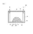
- FIG. 1 is a longitudinal cross-sectional view schematically showing a cross-sectional structure of a nonaqueous electrolyte secondary battery according to an embodiment.
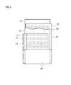
- FIG. 2 is a schematic diagram illustrating a configuration of a wound electrode body according to an embodiment.
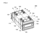
- FIG. 3 is a perspective view schematically showing an assembled battery in which a plurality of nonaqueous electrolyte secondary batteries (unit cells) according to an embodiment are combined.
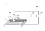
- FIG. 4 is a schematic diagram for explaining a resistance measuring method according to an embodiment.
- FIG. 5 is a graph showing a distribution of resistance values of the negative electrode active material layer according to an example.
- FIG. 6 is a graph showing the relationship between the standard deviation ⁇ of the resistance value, the capacity retention rate of the battery, and the negative electrode heat generation amount.
- a nonaqueous electrolyte secondary battery includes an electrode body formed by laminating a positive electrode and a negative electrode via a separator, and a non-aqueous electrolyte.
- an electrode body wound in a flat shape a wound electrode body
- the present invention will be described in detail by taking as an example a non-aqueous electrolyte secondary battery in which the non-aqueous electrolyte is accommodated in a flat rectangular parallelepiped container (battery case).
- FIG. 1 shows a schematic configuration of a nonaqueous electrolyte secondary battery according to an embodiment of the present invention.
- FIG. 1 is a longitudinal sectional view schematically showing a sectional structure of a nonaqueous electrolyte secondary battery 100.
- a long positive electrode sheet 10 and a long negative electrode sheet 20 are wound flatly via a long separator sheet 40.
- the electrode body (wound electrode body) 80 and the non-aqueous electrolyte (not shown) are accommodated in a battery case 50 having a shape (flat box shape) that can accommodate the wound electrode body.
- the battery case 50 includes a flat rectangular parallelepiped (box-shaped) battery case main body 52 having an open upper end, and a lid 54 that closes the opening.
- a positive terminal 70 for external connection that is electrically connected to the positive electrode of the wound electrode body 80 and a negative electrode that is electrically connected to the negative electrode of the wound electrode body 80.
- a terminal 72 is provided.
- the lid 54 is also provided with a safety valve 55 for discharging the gas generated inside the battery case 50 to the outside of the battery case 50 as in the case of the battery case of the conventional nonaqueous electrolyte secondary battery. .
- the material of the battery case 50 examples include metal materials such as aluminum and steel; resin materials such as polyphenylene sulfide resin and polyimide resin.
- relatively light metals for example, aluminum and aluminum alloys
- the shape of the case is a rectangular parallelepiped shape here, for example, a circular shape (cylindrical shape, coin shape, button shape), hexahedral shape (rectangular shape, cubic shape), bag shape, and The shape etc. which processed and deformed them can also be employ
- FIG. 2 is a schematic diagram showing a configuration of the wound electrode body 80 shown in FIG.
- the wound electrode body 80 includes a long sheet-like positive electrode (positive electrode sheet) 10 and a long sheet-like negative electrode (negative electrode sheet) 20 before assembly.
- the positive electrode sheet 10 includes a long positive electrode current collector 12 and a positive electrode active material layer 14 formed on at least one surface (typically both surfaces) along the longitudinal direction.
- the negative electrode sheet 20 includes a long negative electrode current collector 22 and a negative electrode active material layer 24 formed on at least one surface (typically both surfaces) along the longitudinal direction.
- a separator 40 that prevents direct contact between the positive electrode active material layer 14 and the negative electrode active material layer 24 is disposed.
- two long sheet-like separators 40 are used.
- Such a wound electrode body 80 is obtained by, for example, winding a laminated body in which the positive electrode sheet 10, the separator sheet 40, the negative electrode sheet 20, and the separator sheet 40 are stacked in this order in the longitudinal direction, It can be produced by forming into a flat shape by pressing and curling.
- the central portion is formed on the surface of the positive electrode current collector 12.
- a wound core portion is formed in which the positive electrode active material layer 14 and the negative electrode active material layer 24 formed on the surface of the negative electrode current collector 22 are overlapped and densely stacked. Further, at both ends of the wound electrode body 80 in the winding axis direction, the positive electrode active material layer non-formed portion of the positive electrode sheet 10 and the negative electrode sheet 20 and the negative electrode active material layer non-formed portion are respectively outward from the wound core portion. It sticks out.
- a positive electrode current collector plate is attached to the positive electrode side protruding portion, and a negative electrode current collector plate is attached to the negative electrode side protruding portion, which are electrically connected to the positive electrode terminal 70 (FIG. 1) and the negative electrode terminal 72 (FIG. 1). It is connected.
- the positive electrode sheet 10 includes a positive electrode current collector 12 and a positive electrode active material layer 14 including at least a positive electrode active material formed on the positive electrode current collector.
- a conductive member made of a metal having good conductivity for example, aluminum, nickel, titanium, stainless steel, or the like.
- the positive electrode active material layer 14 includes at least a positive electrode active material.
- a positive electrode active material one or more of various materials known to be usable as a positive electrode active material of a non-aqueous electrolyte secondary battery can be used without particular limitation.
- Preferable examples include layered and spinel-based lithium composite metal oxides (for example, LiNiO 2 , LiCoO 2 , LiFeO 2 , LiMn 2 O 4 , LiNi 0.5 Mn 1.5 O 4 , LiCrMnO 4 ) and olivine systems. (For example, LiFePO 4 ).
- a lithium nickel cobalt manganese composite oxide for example, LiNi 1/3 Co 1/3 Mn having a layered structure containing Li, Ni, Co, and Mn (typically a layered rock salt structure belonging to a hexagonal system). 1/3 O 2 ) can be suitably used.
- a lithium nickel cobalt manganese composite oxide is an oxide containing only Li, Ni, Co and Mn as constituent metal elements, and at least one other metal element in addition to Li, Ni, Co and Mn ( That is, it is meant to include oxides containing transition metal elements and / or typical metal elements other than Li, Ni, Co and Mn.
- Such metal elements include magnesium (Mg), calcium (Ca), strontium (Sr), titanium (Ti), zirconium (Zr), vanadium (V), niobium (Nb), chromium (Cr), molybdenum (Mo), Tungsten (W), iron (Fe), rhodium (Rh), palladium (Pb), platinum (Pt), copper (Cu), zinc (Zn), boron (B), aluminum (Al), gallium (Ga), It may be one or more elements of indium (In), tin (Sn), lanthanum (La), and cerium (Ce).
- the addition amount (blending amount) of these metal elements is not particularly limited, but is usually 0.01 to 5% by mass (eg 0.05 to 2% by mass, typically 0.1 to 0.8% by mass). possible. By setting the amount within the above range, excellent battery characteristics (for example, high energy density) can be realized.
- a general formula: LiMn 2 ⁇ p M p O 4 (wherein p is 0 ⁇ p ⁇ 2 and typically 0 ⁇ p ⁇ 1 (for example, 0.2 ⁇ p ⁇ 0.6)), and a lithium transition metal composite oxide having a spinel structure.
- M can be any metallic or non-metallic element other than Mn.
- a composition in which M contains at least one transition metal element (for example, one or more selected from Ti, Cr, Fe, Co, Ni, Cu and Zn) is preferable.
- the working potential of the positive electrode is about 4.5 V or higher (and moreover 4.4 higher than that of a general non-aqueous electrolyte secondary battery (the upper limit of the working potential is about 4.1 to 4.2 V)). 6V or more, for example, 4.7V or more). Therefore, a much higher energy density can be realized.
- the positive electrode active material layer 14 may be made of one or more materials that can be used as a constituent component of the positive electrode active material layer 14 in a general non-aqueous electrolyte secondary battery as necessary. May be contained.
- a material include a conductive material and a binder.
- the conductive material for example, carbon materials such as various carbon blacks (typically acetylene black and ketjen black), coke, activated carbon, graphite, carbon fiber, and carbon nanotube can be suitably used.
- the binder for example, a vinyl halide resin such as polyvinylidene fluoride (PVdF); a polyalkylene oxide such as polyethylene oxide (PEO); and the like can be preferably used.
- the proportion of the positive electrode active material in the entire positive electrode active material layer 14 is suitably about 60% by mass or more (typically 60 to 99% by mass), and usually about 70 to 95% by mass. Is preferred.
- the proportion of the conductive material in the entire positive electrode active material layer 14 can be, for example, approximately 2 to 20% by mass, and is preferably approximately 3 to 10% by mass.
- the ratio of the binder to the entire positive electrode active material layer 14 can be, for example, about 0.5 to 10% by mass, and is usually preferably about 1 to 5% by mass.
- the mass (weight per unit area) of the positive electrode active material layer 14 provided per unit area of the positive electrode current collector 12 is 3 mg / cm 2 or more per side of the positive electrode current collector 12 from the viewpoint of securing a sufficient battery capacity (for example, 5 mg / cm 2 or more, typically 10 mg / cm 2 or more). Further, from the viewpoint of securing input / output characteristics, the positive electrode current collector 12 may be 50 mg / cm 2 or less per side (for example, 40 mg / cm 2 or less, typically 20 mg / cm 2 or less). In the configuration having the positive electrode active material layer 14 on both surfaces of the positive electrode current collector 12 as in this embodiment, the mass of the positive electrode active material layer 14 provided on each surface of the positive electrode current collector 12 is approximately the same. It is preferable to do.
- the average thickness per one side of the positive electrode active material layer 14 is, for example, 40 ⁇ m or more (typically 50 ⁇ m or more), and may be 100 ⁇ m or less (typically 80 ⁇ m or less).
- the density of the positive electrode active material layer 14 is preferably 1 to 4 g / cm 3 (for example, 1.5 to 3.5 g / cm 3 ).
- the porosity of the positive electrode active material layer 14 may be set to, for example, 10 to 50% by volume (typically 20 to 40% by volume). When one or more of the above properties are satisfied, an appropriate void can be maintained in the positive electrode active material layer 14, and the nonaqueous electrolyte can be sufficiently infiltrated.
- the electroconductivity in the positive electrode active material layer 14 can be kept favorable, and an increase in resistance can be suppressed. Furthermore, the mechanical strength (shape retention) of the positive electrode active material layer 14 can be ensured, and better cycle characteristics can be exhibited.
- the "porosity" as used herein multiplied by 100 and divided by the apparent volume of the total pore volume (cm 3)
- the active material layer obtained by the above measurement of a mercury porosimeter (cm 3) Value.
- the apparent volume can be calculated by the product of the area (cm 2 ) and the thickness (cm) in plan view.
- a method for producing such a positive electrode sheet 10 is not particularly limited. For example, first, a positive electrode active material and a material used as necessary are dispersed in an appropriate solvent, and a paste-like or slurry-like composition (positive electrode) Active material layer forming slurry) is prepared. Next, the prepared positive electrode active material layer forming slurry is applied to the elongated positive electrode current collector 12, and the solvent contained in the slurry is removed. Thereby, the positive electrode sheet 10 provided with the positive electrode active material layer 14 on the positive electrode current collector 12 can be produced.
- the solvent any of an aqueous solvent and an organic solvent can be used. For example, N-methyl-2-pyrrolidone (NMP) can be used.
- the operation of applying the slurry can be performed using an appropriate coating apparatus such as a gravure coater, a slit coater, a die coater, a comma coater, or a dip coater.
- an appropriate coating apparatus such as a gravure coater, a slit coater, a die coater, a comma coater, or a dip coater.
- the removal of the solvent can also be performed by conventional general means (for example, heat drying or vacuum drying).
- the property (namely, average thickness, density, porosity) of the positive electrode active material layer 14 as described above is, for example, that the positive electrode sheet 10 is appropriately pressed after the positive electrode active material layer 14 is formed. Can be adjusted by.
- Various conventionally known press methods such as a roll press method and a flat plate press method can be employed for the press treatment. Further, such processing may be performed once or may be performed two or more times.
- the negative electrode sheet 20 includes a negative electrode current collector 22 and a negative electrode active material layer 24 including at least a negative electrode active material formed on the negative electrode current collector.
- a conductive material made of a metal having good conductivity for example, copper, nickel, titanium, stainless steel, etc.
- the negative electrode active material layer 24 includes at least a negative electrode active material.
- the negative electrode active material one or more of various materials known to be usable as a negative electrode active material for a non-aqueous electrolyte secondary battery can be used without particular limitation.
- Preferable examples include carbon materials such as graphite (graphite), non-graphitizable carbon (hard carbon), graphitizable carbon (soft carbon), and carbon nanotubes.
- graphite-type materials especially natural graphite
- natural graphite such as natural graphite and artificial graphite
- a battery including a graphite-based material in a negative electrode In general, in a battery including a graphite-based material in a negative electrode, components (for example, non-aqueous) contained in a non-aqueous electrolyte solution when charging / discharging is repeated under severe conditions (for example, high temperature environment and / or high input / output density). Solvent and supporting salt) are gradually decomposed, and the energy density may be lowered.
- solvent and supporting salt are gradually decomposed, and the energy density may be lowered.
- a suitable coating derived from the BP-oxalato compound is formed on the surface of the negative electrode active material, such decomposition hardly occurs and a high energy density can be realized over a long period of time. .
- a negative electrode active material may be a particle form or a powder form.
- the average particle size of the particulate negative electrode active material may be 20 ⁇ m or less (typically 1 to 20 ⁇ m, for example, 5 to 15 ⁇ m).
- the specific surface area is 1 m 2 / g or more (typically 2.5 m 2 / g or more, for example, 2.8 m 2 / g or more), and 10 m 2 / g or less (typically 3.5 m 2 / G or less, for example 3.4 m 2 / g or less).
- a negative electrode active material satisfying one or two of the above properties can ensure a wide charge carrier reaction field even when a coating film derived from a BP-oxalato compound is formed on the surface, and a higher battery. Characteristics (for example, high input / output characteristics) can be realized.
- the “average particle size” means particles corresponding to 50% cumulative from the fine particle side in the volume-based particle size distribution measured by particle size distribution measurement based on a general laser diffraction / light scattering method.
- diameter (D 50 particle size, also called median diameter.) refers to.
- BET specific surface area (m 2 / g) means a gas adsorption amount measured by a gas adsorption method (fixed capacity adsorption method) using nitrogen (N 2 ) gas as an adsorbate. The value calculated by analyzing by the BET method (for example, the BET 1-point method).
- the negative electrode active material layer 24 is made of one or more materials that can be used as a constituent component of the negative electrode active material layer in a general non-aqueous electrolyte secondary battery as necessary. May be contained.
- materials include binders and various additives.
- the binder for example, a polymer material such as styrene butadiene rubber (SBR), polyvinylidene fluoride (PVdF), polytetrafluoroethylene (PTFE), or the like can be suitably used.
- various additives such as a thickener, a dispersant, and a conductive material can be appropriately used.
- CMC carboxymethylcellulose
- MC methylcellulose
- the proportion of the negative electrode active material in the whole negative electrode active material layer 24 is suitably about 50% by mass or more, and preferably 90 to 99% by mass (for example, 95 to 99% by mass).
- the ratio of the binder to the whole negative electrode active material layer 24 can be, for example, about 1 to 10% by mass, and usually about 1 to 5% by mass.
- the proportion of the thickener in the negative electrode active material layer 24 as a whole can be, for example, about 1 to 10% by mass, and usually about 1 to 5% by mass. .
- the mass (weight per unit area) of the negative electrode active material layer 24 provided per unit area of the negative electrode current collector 22 is 3 mg / cm 2 or more per side of the negative electrode current collector 22 from the viewpoint of securing sufficient battery capacity (typically Specifically, it is preferable to set it to 5 mg / cm 2 or more, for example, 7 mg / cm 2 or more. Further, from the viewpoint of securing input / output characteristics, the negative electrode current collector 22 may be 30 mg / cm 2 or less (typically 20 mg / cm 2 or less, for example, 15 mg / cm 2 or less) per one surface. In the configuration having the negative electrode active material layer 24 on both surfaces of the negative electrode current collector 22 as in this embodiment, the mass of the negative electrode active material layer 24 provided on each surface of the negative electrode current collector 22 is approximately the same. It is preferable to do.
- the thickness per one side of the negative electrode active material layer 24 is, for example, 40 ⁇ m or more (preferably 50 ⁇ m or more) and 100 ⁇ m or less (preferably 80 ⁇ m or less). Further, the density of the negative electrode active material layer 24 may be, for example, about 0.5 to 2 g / cm 3 (preferably 1 to 1.5 g / cm 3 ). Further, the porosity of the negative electrode active material layer 24 may be, for example, about 5 to 50% by volume (preferably 35 to 50% by volume). When one or more of the above properties are satisfied, a higher energy density can be realized. Moreover, a moderate space
- a method for producing such a negative electrode sheet 20 is not particularly limited. For example, first, a negative electrode active material and a material used as necessary are dispersed in an appropriate solvent, and a paste-like or slurry-like composition (negative electrode Active material layer forming slurry) is prepared. And the prepared slurry for negative electrode active material layer formation is provided to the elongate negative electrode collector 22, and the solvent contained in this slurry is removed. Thereby, the negative electrode sheet 20 provided with the negative electrode active material layer 24 on the negative electrode current collector 22 can be produced.
- the solvent any of an aqueous solvent and an organic solvent can be used. For example, water can be used.
- the properties (porosity, thickness, density) of the negative electrode active material layer 24 can be adjusted by performing an appropriate press treatment in the same manner as the positive electrode active material layer 14 described above.
- a film substantially derived from the BP-oxalato compound is formed on the negative electrode active material layer 24 (specifically, the surface of the negative electrode active material).
- Such coatings typically include boron (B) and / or phosphorus (P) atoms, oxalate ions (C 2 O 4 2 ⁇ ), and charge carrier ions (eg, Li + ). .
- it may be in the form of LiBO 2 F, LiBO 3 , LiPO 2 F 2 , LiPO 3 F, LiPO 4 or the like.
- This coating stabilizes the interface between the negative electrode active material (typically a graphite material) and the non-aqueous electrolyte, so that the decomposition of the non-aqueous electrolyte during the subsequent charge / discharge can be suppressed.
- “substantially” is an expression used for the main constituent components of the film containing boron atoms and / or phosphorus atoms, and typically 80 mol% or more (preferably 85 mol% or more) of the film. , More preferably 90 mol% or more) is derived from a BP-oxalato compound.
- the coating film contains components derived from components other than the BP-oxalato compound, such as decomposition products of other components constituting the non-aqueous electrolyte (specifically, supporting salts and non-aqueous solvents). It can be tolerated.
- the qualitative and quantitative determination of the coating film formed on the surface of the negative electrode active material can be measured by, for example, a general ion chromatography (IC) method.
- the battery is first disassembled, the negative electrode (negative electrode active material layer) is taken out, immersed in an appropriate solvent (for example, EMC), washed, cut into a predetermined size, and used as a measurement sample.
- an appropriate solvent for example, EMC
- the coating component ion derived from the BP-oxalato compound
- BP ⁇ contained per unit area (1 cm 2 )
- the coating amount ( ⁇ M / cm 2 ) derived from the oxalato compound can be determined.
- the coating film on the surface of the negative electrode active material As a method for qualitatively and quantitatively determining the coating film on the surface of the negative electrode active material, the case where ion chromatography is used is specifically shown above. However, the method is not limited to this. The same analysis can be performed by (ICP-AES: Inductively Coupled Plasma-Atomic Emission Spectrometry), X-ray Absorption Fine Structure (XAFS) and the like.
- ICP-AES Inductively Coupled Plasma-Atomic Emission Spectrometry
- XAFS X-ray Absorption Fine Structure
- the technique disclosed herein is characterized in that the resistance value of the negative electrode active material layer is within a predetermined range. That is, for at least a part of the negative electrode active material layer, the resistance value measured at a plurality of points at equal intervals in the line direction from the predetermined laminated surface of the electrode body to the other laminated surface opposite to the linear direction.
- the standard deviation ⁇ is 3.0 or more and 7.2 or less. By setting the standard deviation ⁇ within the range, it is possible to achieve a battery performance that is excellent during normal use and that is also excellent in tolerance during overcharge. In a preferred embodiment, the standard deviation ⁇ is 3.0 or more and 5.0 or less. Thereby, the battery performance which was more excellent at the time of normal use can be exhibited, and the effect of the present invention can be exhibited at a higher level.
- the standard deviation ⁇ of the resistance value is, for example, the following process: a preparation step of the negative electrode active material layer (measurement object); a measurement point setting process; a resistance value measurement process at the measurement point; a standard deviation ⁇ calculation process; It can obtain
- the battery is disassembled and the negative electrode active material layer (typically, the negative electrode having the negative electrode active material layer supported on the surface of the negative electrode current collector) is taken out and an appropriate solvent (for example, And a nonaqueous solvent described later).
- the measurement point reaches from the predetermined one end (predetermined one laminated surface in the state of the electrode body) to another one end (the opposite laminated surface) in the linear direction.
- a plurality are set at equal intervals in the line direction.
- the measurement point is preferably set so as to include the vicinity of the central portion (central portion) of the negative electrode active material layer.
- the negative electrode active material layer 24 of the inner flat portion excluding at least the outermost periphery, which is the negative electrode active material layer 24 constituting the wound electrode body.
- the negative electrode active material layer constituting the laminated electrode body in which the substantially square positive electrode and negative electrode are laminated a plurality of the negative electrode active material layers at equal intervals in the line direction from one corner to the other corner in a diagonal line. It is preferable to set the measured points. There may be a plurality of points to be measured, that is, two or more points. Typically, the points to be measured are odd points that are set at equal intervals in a line shape including the vicinity of the center.
- the point to be measured is usually preferably 5 points or more, and typically 7 points or more, for example, 11 points or more. Further, from the viewpoint of work efficiency, it is preferably 31 points or less, for example, 25 points or less.
- the resistance measuring apparatus 300 shown in FIG. 4 includes a Lugin tube type counter electrode 210, an AC impedance measuring unit 230, and a control unit 240.
- the Lugin tube-type counter electrode 210 includes a Lugin tube main body 212 and a measurement unit 218 connected to the main body.
- the measurement unit 218 is a part that is brought into contact with the measurement point of the negative electrode active material layer 24 through a nonaqueous electrolytic solution.
- the cross-sectional area (contact area with the negative electrode active material layer 24) of the end of the measurement unit is generally 0.01 to 0.1 cm 2 (typically 0.02 to 0). About 0.05 cm 2 ).
- the shape of the edge part of the measurement part 218 is circular.
- the lugin tube body 212 is preferably made of a material having the above-mentioned end shape and excellent in chemical resistance.
- the Lugin tube body 212 has a predetermined non-aqueous electrolyte 216 and a counter electrode 214 disposed in the non-aqueous electrolyte.
- the non-aqueous electrolyte 216 the same non-aqueous electrolyte secondary battery can be used.
- the counter electrode 214 for example, the above-described positive electrode or negative electrode can be used.
- the area of the counter electrode 214 is 100 times or more (typically 200 times or more, preferably 300 times or more, more preferably 500 times or more) than the area of the end of the measurement unit 218 (contact area with the negative electrode active material layer 24). ) It is preferable to set wide. As a result, the reaction resistance of the counter electrode 214 can be made negligibly small. More specifically, for example, the resistance of the counter electrode 214 can be set to about 1/50 or less (preferably 1/100 or less) of the inspection target (measurement point). Therefore, the resistance derived from the coating formed on the negative electrode active material layer 24 can be accurately measured.
- an electrode that is rolled up as a counter electrode 214 is accommodated in the Lugin tube body 212.
- the AC impedance measuring unit 230 electrically connects the counter electrode 214 and the measurement point of the negative electrode active material layer 24.
- the AC impedance measuring unit 230 can be arbitrarily selected from those conventionally used as a general impedance measuring device. For example, a Solartron 1287 type potentio / galvanostat and a 1255B type frequency response analyzer can be used in combination.
- the control unit 240 controls measurement of AC impedance, adjustment of the Lugin tube type counter electrode 210, and the like based on predetermined information.
- the resistance value can be measured by using the resistance inspection apparatus 300 according to the following procedures (1) to (4).
- (Procedure 1) A Lugin tube type counter electrode as described above is prepared.
- (Procedure 2) The measurement part of the Lugin tube type counter electrode is brought into contact with the measurement point of the negative electrode active material layer, and the counter electrode and the measurement point of the negative electrode active material layer are electrically connected via the non-aqueous electrolyte. Connect to.
- (Procedure 3) An alternating current or an alternating voltage is input between the electrically connected counter electrode and the measurement point to measure impedance.
- (Procedure 4) A resistance value is calculated based on the measurement result of the impedance.
- the frequency region for measuring impedance may be set to, for example, about 100 kHz to 0.01 Hz (typically 10 kHz to 0.1 Hz, for example, 1 kHz to 0.1 Hz) from the viewpoint of measurement accuracy, measurement time, and the like. it can.
- the input voltage can be set to about 100 to 1000 mV (typically 200 to 1000 mV, for example, 300 to 1000 mV).
- the resistance value can be easily calculated by subtracting the value of the intersection point intersecting the real axis on the high frequency side from the value of the intersection point intersecting the real axis on the low frequency side of the Cole-Cole plot, for example. Alternatively, it can be obtained by analyzing the shape of the Cole-Cole plot in comparison with an appropriately selected equivalent circuit (by curve fitting). Then, a statistical standard deviation ⁇ is calculated based on the resistance value at each measurement point.
- the separator sheet 40 interposed between the positive and negative electrode sheets 10 and 20 may be any sheet as long as it insulates the positive electrode active material layer 14 and the negative electrode active material layer 24 and has a nonaqueous electrolyte holding function and a shutdown function.
- Preferable examples include porous resin sheets (films) made of a resin such as polyethylene (PE), polypropylene (PP), polyester, cellulose, and polyamide.
- a porous resin sheet may have a single-layer structure or a laminated structure of two or more layers (for example, a three-layer structure in which PP layers are laminated on both sides of a PE layer).
- the average thickness of the porous resin sheet is preferably about 10 to 40 ⁇ m, for example.
- the separator sheet 40 may be configured to include a porous heat-resistant layer on one side or both sides (typically, one side) of the porous resin sheet.
- a porous heat-resistant layer can be, for example, a layer containing an inorganic material (inorganic fillers such as alumina particles can be preferably employed) and a binder.
- it may be a layer containing insulating resin particles (for example, particles of polyethylene, polypropylene, etc.).
- the nonaqueous electrolytic solution contains at least a supporting salt in a nonaqueous solvent.
- the non-aqueous electrolyte is in a liquid state at normal temperature (for example, 25 ° C.). In a preferred embodiment, the non-aqueous electrolyte is always in a liquid state in the battery use environment (for example, in a temperature environment of ⁇ 30 to 60 ° C.).
- non-aqueous solvent organic solvents such as various carbonates, ethers, esters, nitriles, sulfones, and lactones used in the electrolyte of general non-aqueous electrolyte secondary batteries can be used.
- organic solvents such as various carbonates, ethers, esters, nitriles, sulfones, and lactones used in the electrolyte of general non-aqueous electrolyte secondary batteries
- EC ethylene carbonate
- PC propylene carbonate
- DEC diethyl carbonate
- DMC dimethyl carbonate
- EMC ethyl methyl carbonate
- Such a non-aqueous solvent can be used individually by 1 type or in combination of 2 or more types as appropriate.
- a high dielectric constant solvent and a low viscosity solvent are mixed and used.
- the high dielectric constant solvent examples include EC
- examples of the low viscosity solvent examples include DMC and EMC.
- one or more carbonates are included, and the total volume of these carbonates is 60% by volume or more (more preferably 75% by volume or more, more preferably 90% by volume or more) of the total volume of the nonaqueous solvent.
- the non-aqueous solvent occupying 100% by volume may be preferably used.
- ethylene carbonate accounts for 20 volume% or more and 40 volume% or less of the entire non-aqueous solvent.
- the supporting salt is the same as that of a general non-aqueous electrolyte secondary battery as long as it contains a charge carrier (for example, lithium ion, sodium ion, magnesium ion, etc., lithium ion in a lithium ion secondary battery).
- a charge carrier for example, lithium ion, sodium ion, magnesium ion, etc., lithium ion in a lithium ion secondary battery.
- the charge carrier is lithium ion
- lithium salts such as LiPF 6 , LiBF 4 , LiClO 4 , LiAsF 6 , Li (CF 3 SO 2 ) 2 N, LiCF 3 SO 3 are exemplified.
- Such a supporting salt can be used singly or in combination of two or more.
- LiPF 6 may be mentioned as particularly preferred support salt.
- the non-aqueous electrolyte is preferably prepared so that the concentration of the supporting salt is within the range of 0.7 to 1.3 mol / L.
- the non-aqueous electrolyte contains a BP-oxalato compound at least in the state of the battery assembly (the state before the charging process).
- the compound is reduced and decomposed at the negative electrode by the charging process (typically, the first charging process), and is bonded (attached) to the surface of the negative electrode active material as a high-quality film. Therefore, it is not always necessary that the compound remains in the non-aqueous electrolyte after the initial charging process.
- the non-aqueous electrolyte may further contain various additives as long as the effects of the present invention are not significantly impaired.
- additives include film forming materials other than BP-oxalato compounds (for example, vinylene carbonate, vinyl ethylene carbonate, fluoroethylene carbonate), compounds that can generate gas upon polymerization when overcharged (for example, biphenyl, cyclohexylbenzene). ), Various dispersants and thickeners.
- the nonaqueous electrolyte secondary battery as described above can be suitably manufactured by a manufacturing method including the following steps, for example.
- Preparation step preparing an electrode body and a non-aqueous electrolyte.
- Construction process housing the electrode body and the non-aqueous electrolyte in a battery case to construct a battery assembly.
- Holding step holding the battery assembly constructed above in a temperature range lower than 25 ° C. for a predetermined time.
- Charging process step performing a charging process between the positive electrode and the negative electrode.
- a suitable film that is, a film having a standard deviation ⁇ of resistance value of 3.0 to 7.2
- each process is demonstrated in order.
- an electrode body and a non-aqueous electrolyte are prepared.
- the electrode body has a configuration in which a positive electrode having a positive electrode active material layer and a negative electrode having a negative electrode active material layer are laminated via a separator.
- As the positive electrode, the negative electrode, and the separator constituting the electrode body those already described above can be used.
- the nonaqueous electrolytic solution typically includes a nonaqueous solvent, a supporting salt, and a BP-oxalato compound. As the non-aqueous solvent and the supporting salt, those already described above can be used.
- the BP-oxalato compound one produced by a known method or one obtained by purchasing a commercially available product is not particularly limited, and one or more kinds can be used.
- at least one oxalate ion (C 2 O 4 2 ⁇ ) is coordinated to a boron (B) atom as a central atom.
- An oxalato complex compound (B atom-containing oxalate salt) having a structural moiety can be used.
- Such a compound can be reduced and decomposed at the negative electrode during the charging process (typically, the first charging process), and can adhere (bond) to the surface of the negative electrode active material as a high-quality film having low resistance and excellent stability. .
- a + in formulas (V) and (VI) may be either an inorganic cation or an organic cation.
- inorganic cations include alkali metal cations such as Li, Na, and K; alkaline earth metal cations such as Be, Mg, and Ca; other, Ag, Zn, Cu, Co, Fe, Ni, Mn, and Ti , Pb, Cr, V, Ru, Y, metal cations such as lanthanoids, actinoids, protons, and the like.
- organic cations include tetraalkylammonium ions such as tetrabutylammonium ion, tetraethylammonium ion and tetramethylammonium ion; trialkylammonium ions such as triethylmethylammonium ion and triethylammonium ion; other pyridinium ions and imidazolium ions Tetraethylphosphonium ion, tetramethylphosphonium ion, tetraphenylphosphonium ion, triphenylsulfonium ion, triethylsulfonium ion; and the like.
- tetraalkylammonium ions such as tetrabutylammonium ion, tetraethylammonium ion and tetramethylammonium ion
- trialkylammonium ions such as triethyl
- R 1 and R 2 are each independently a halogen atom of F, Cl, Br, etc. (preferably F); a par atom having 1 to 10 carbon atoms (preferably 1 to 3 carbon atoms).
- oxalato complex compound examples include lithium bis (oxalato) borate (LIBOB) represented by the above formula (I); lithium difluorooxalate borate (LBFO) represented by the above formula (II); Is mentioned.
- LIBOB lithium bis (oxalato) borate
- LBFO lithium difluorooxalate borate
- At least one oxalate ion (C 2 O 4 2 ⁇ ) as represented by the above formulas (III) and (IV) is coordinated to a phosphorus (P) atom as a central atom.
- an oxalato complex compound (P atom-containing oxalate salt) having a six-coordinate structural moiety.
- the cation is a lithium ion
- other cations may be used in the same manner as A + in the formulas (V) and (VI).
- F in the above formulas (III) and (IV) is independently F and other halogen atoms (for example, Cl and Br, preferably F) as in R 1 and R 2 in the formula (V).
- oxalato complex compound examples include lithium difluorobis (oxalate) phosphate (LPFO) represented by the above formula (III); lithium tetrafluorooxalate phosphate represented by the above formula (IV); lithium tris. (Oxalato) phosphate; and the like.
- the reduction potential (vs. Li / Li + ) of the BP-oxalato compound is higher than other components (typically non-aqueous solvents) contained in the non-aqueous electrolyte. That is, an embodiment in which the reduction potential of the BP-oxalato compound is the highest among the components contained in the nonaqueous electrolytic solution is preferable.
- the reduction potential of LIBOB is approximately 1.73V (vs. Li / Li + )
- Li / Li + generally It is preferably equal or lower (typically lower than 0.1V, for example lower than 0.5V, especially lower than 0.8V).
- a film derived from the BP-oxalato compound can be suitably formed on the surface of the negative electrode active material.
- the amount of BP-oxalato compound added may vary depending on, for example, the type and properties of the negative electrode active material (eg, particle size and specific surface area). In general, the smaller the average particle size and / or the larger the BET specific surface area, the more the suitable amount of BP-oxalato compound added tends to increase. For this reason, although not particularly limited, when the addition amount is too small, the film formed on the surface of the negative electrode active material becomes thin, and the durability (storage characteristics and rapid charge / discharge characteristics) of the battery may be reduced. On the other hand, when the addition amount is too large, the film formed on the surface of the negative electrode active material becomes thick, and there is a concern that the resistance accompanying charge / discharge increases.
- the addition amount is too small, the film formed on the surface of the negative electrode active material becomes thin, and the durability (storage characteristics and rapid charge / discharge characteristics) of the battery may be reduced.
- the addition amount is too large, the film formed on the surface of the negative electrode active material becomes thick,
- the concentration of the BP-oxalato compound in the non-aqueous electrolyte is 0.005 mol / L or more (for example, 0.01 mol / L or more) with respect to the non-aqueous electrolyte, .2 mol / L or less (for example, 0.1 mol / L or less, preferably 0.07 mol / L or less).
- the addition amount is in the above range, the effect of the present invention can be exhibited at a higher level.
- Such a nonaqueous electrolytic solution can be typically prepared by uniformly dissolving a supporting salt and a BP-oxalato compound in a nonaqueous solvent.
- a BP-oxalato compound is directly added and impregnated into the electrode body (typically, the negative electrode active material layer or the separator) as described above, and the electrode body and a nonaqueous solvent containing only the supporting salt are added.
- the BP-oxalato compound can be eluted in the non-aqueous electrolyte by being housed in the battery case.
- the amount of the BP-oxalato compound used in the construction of the battery is, for example, positive and negative electrode active material by the above-described ion chromatography technique. Quantifying the coating derived from the compound contained in the layer; analyzing the non-aqueous electrolyte accumulated in the battery case by ion chromatography and quantifying the BP-oxalato compounds and chemical species derived from their decomposition products It can be generally grasped by the method of doing;
- the electrode body and the non-aqueous electrolyte are accommodated in a battery case.
- a battery case typically, first, an electrode body is accommodated in a battery case, and the inside of the battery case is depressurized to about -70 to -90 kPa.
- the non-aqueous electrolyte can penetrate into the electrode body.
- a non-aqueous electrolyte secondary battery assembly can be constructed by sealing the opening of the battery case by welding or the like.
- the pressure inside the battery assembly immediately after construction is almost equal to the atmospheric pressure.
- ⁇ (3) Holding step> the battery assembly constructed as described above is held (leaved) for a predetermined time in a temperature range lower than 25 ° C.
- the nonaqueous electrolytic solution containing the BP-oxalato compound is suitably distributed over the entire electrode body, and the concentration of the BP-oxalato compound is appropriately homogenized in the electrode body.
- the “temperature range lower than 25 ° C.” is typically lower than 20 ° C., for example, 18 ° C. or lower, preferably 15 ° C. or lower.
- the lower limit of the temperature is not particularly limited because it depends on, for example, the properties of the negative electrode (the density and thickness of the negative electrode active material layer) and the retention time of this step, but typically 5 ° C. from the viewpoint of work efficiency and cost. It can be higher, for example, 7 ° C. or higher, preferably 8 ° C. or higher, more preferably 10 ° C. or higher.
- the holding time in the low temperature range is not particularly limited because it depends on, for example, the properties of the negative electrode (the density and thickness of the negative electrode active material layer), the holding temperature in this step, and the like. It is preferably about 5 to 20 hours (for example, 10 to 16 hours).
- ⁇ (4) Charging process> a charging process is performed between the positive electrode and the negative electrode.
- the BP-oxalato compound is reduced and decomposed at the negative electrode, and a suitable film (that is, a film having a resistance standard deviation ⁇ of 3.0 to 7.2) is formed on the surface of the negative electrode active material.
- Such charging treatment is performed so that the potential of the negative electrode (vs. Li / Li + ) is lower than the reduction potential of the BP-oxalato compound contained in the non-aqueous electrolyte.
- the charge treatment is carried out until it is 0.05 V or more (typically 0.1 V or more, such as 0.3 V or more, particularly 0.5 V) lower than the reduction potential of the compound contained in the electrolytic solution. I do.
- the voltage between the positive and negative terminals (typically the highest voltage reached) in the charging process varies depending on, for example, the type of the BP-oxalato compound used, but it is 3.9 to 4.2 V (eg, 3.95 to It is good to set it to about 4.15V).
- the charging process may be performed by a constant current charging method (CC charging) from the start of charging until the negative electrode potential reaches a predetermined value (or until the voltage between the positive and negative terminals reaches a predetermined value), After charging with a constant current until the predetermined potential (or voltage) is reached, charging may be performed with a constant voltage (CCCV charging).
- CCCV charging constant voltage
- the charging process is performed by a CCCV charging method.
- the charging rate in CC charging is not particularly limited, but if it is too low, the processing efficiency tends to decrease. On the other hand, if it is too high, the denseness of the formed film may be insufficient, or the positive electrode active material may be deteriorated.
- 0.1 to 2C (typically 0.5 to 1.5C, for example, 0.6 to 1C) is preferable.
- a suitable denseness that is, a low resistance and capable of sufficiently suppressing the reaction with the non-aqueous electrolyte
- the said charge process may be performed once, for example, can also be performed twice or more across a discharge process process.
- other operations that can promote the reductive decomposition of the above compound for example, heating, pressure load, ultrasonic irradiation
- FIG. 3 shows an example of an assembled battery 200 in which nonaqueous electrolyte secondary batteries (unit cells) 100 are connected in series and / or in parallel.
- the battery (single cell) disclosed here is characterized by a higher energy density and output density than conventional batteries. Therefore, an assembled battery formed by connecting a plurality of these single cells to each other (typically in series) can exhibit even higher battery characteristics.
- the assembled battery 200 includes a plurality of (typically 10 or more, preferably about 10 to 30, for example, 20) non-aqueous electrolyte secondary batteries (unit cells) 100, respectively.
- the positive and negative terminals 70 and 72 are inverted one by one so as to be alternately arranged, and the wide surfaces of the battery case are arranged in the facing direction (stacking direction).
- a cooling plate 110 having a predetermined shape is sandwiched between the arranged unit cells 100.
- the cooling plate 110 functions as a heat dissipating member for efficiently dissipating heat generated in each unit cell 100 during use, and preferably a cooling fluid (typically between the unit cells 100). Air) (for example, a shape in which a plurality of parallel grooves extending vertically from one side of the rectangular cooling plate to the opposite side are provided on the surface).
- a cooling plate made of metal having good thermal conductivity or lightweight and hard polypropylene or other synthetic resin is suitable.
- a pair of end plates (restraint plates) 120 are disposed at both ends of the unit cell 100 and the cooling plate 110 arranged as described above.
- One or more sheet-like spacer members 150 as length adjusting means may be sandwiched between the cooling plate 110 and the end plate 120.
- the unit cell 100, the cooling plate 110, and the spacer member 150 arranged in the above manner are applied with a predetermined restraining pressure in the stacking direction by a fastening restraint band 130 attached so as to bridge between both end plates. It is restrained. More specifically, by tightening and fixing the end portion of the restraining band 130 to the end plate 120 with screws 155, the unit cells and the like are restrained so that a predetermined restraining pressure is applied in the arrangement direction.
- the battery disclosed herein can be used for various applications, the effect of adding a BP-oxalato compound is suitably exhibited, and both durability and overcharge resistance can be achieved at a high level. Therefore, taking advantage of such properties, for example, it can be suitably used as a driving power source mounted on a vehicle.
- the type of vehicle is not particularly limited, and examples include plug-in hybrid vehicles (PHV), hybrid vehicles (HV), electric vehicles (EV), electric trucks, motorbikes, electric assist bicycles, electric wheelchairs, electric railways, and the like.
- PUV plug-in hybrid vehicles
- HV hybrid vehicles
- EV electric vehicles
- electric trucks motorbikes
- electric assist bicycles electric wheelchairs
- electric railways electric railways, and the like.
- a vehicle equipped with any of the nonaqueous electrolyte secondary batteries disclosed herein preferably as a power source.
- a non-aqueous electrolyte secondary battery provided in a vehicle is usually in the form of the above assembled battery in which a plurality of single
- LNCM LiNi 1/3 Mn 1/3 Co 1/3 O 2
- AB acetylene black
- PVdF polyvinylidene fluoride
- This slurry is applied to both sides of a 15 ⁇ m thick aluminum foil (positive electrode current collector) with a width of 96 mm, dried and then pressed to form a positive electrode sheet having a positive electrode active material layer on both sides of the positive electrode current collector (total thickness: 170 ⁇ m) Electrode density: 3 g / cm 3 ).
- C natural graphite (C) as a negative electrode active material
- SBR styrene butadiene rubber
- CMC carboxymethyl cellulose
- the slurry was applied to both sides of a long copper foil (negative electrode current collector) having a thickness of 10 ⁇ m with a width of 100 mm, dried and pressed to obtain a negative electrode sheet having a negative electrode active material layer on both sides of the negative electrode current collector (total (Thickness: 150 ⁇ m, electrode density: 1.1 g / cm 3 ).
- the positive electrode sheet and the negative electrode sheet produced above are composed of two separator sheets (here, a three-layer structure in which polypropylene (PP) is laminated on both sides of polyethylene (PE), with a thickness of 20 ⁇ m and a width of 110 mm.
- a flat wound electrode body was produced by pressing and ablating from the side direction.
- the positive electrode terminal and the negative electrode terminal were attached to the lid of the battery case, and these terminals were welded to the positive electrode current collector and the negative electrode current collector exposed at the ends of the wound electrode body, respectively.
- the wound electrode body thus connected to the lid body was housed in the rectangular battery case from the opening, and the opening and the lid were welded.
- the nonaqueous electrolyte was injected from the electrolyte injection hole provided in the lid, and the wound electrode body was impregnated with the nonaqueous electrolyte.
- EC ethylene carbonate
- DMC dimethyl carbonate
- EMC ethyl methyl carbonate
- LiPF 6 was dissolved at a concentration of 1.1 mol / L, and lithium bis (oxalato) borate (LiBOB) as a BP-oxalato compound was dissolved at a concentration of 0.05 mol / L.
- LiBOB lithium bis (oxalato) borate
- the constructed battery assembly was held under the conditions (temperature and time) shown in Table 1, and then the initial charging process was performed in an environment of 25 ° C. Specifically, CC charging was performed until the voltage between the positive and negative terminals reached 4.1 V at a charging rate of 1 C, and then CV charging was performed until the current value reached 0.02 C. As a result, a boron atom-containing film substantially derived from the oxalato complex compound was formed on the surface of the negative electrode active material.
- Example 3 two lithium ion secondary batteries (Example 3) were constructed in the same manner as described above except that the pressure at the time of pressing was adjusted so that the density of the negative electrode active material layer was 1.0 g / cm 3 .
- Lithium deposition test The lithium ion secondary batteries according to Examples 1 to 7 after the rated capacity measurement were subjected to a low-temperature pulse cycle test consisting of a charge pattern and an equivalent discharge pattern simulating the charge current and time generated during vehicle slip grip at low temperatures. It was. Specifically, first, the battery was adjusted to a charged state of SOC 60% in an environment of 25 ° C. The battery was subjected to a rectangular wave cycle test of 6000 cycles in a pulse charge pattern consisting of the following steps 1 and 2 in an environment of 0 ° C. (Step 1) A pulse charge for 10 seconds is performed at a constant current of 20 C and a pause is made for 5 seconds.
- Step 2 A pulse discharge for 10 seconds is performed at a constant current of 20 C, and a pause is made for 5 seconds. Then, the discharge capacity (capacity after the pulse test) was measured under the same conditions as the initial capacity, and the ratio “(battery capacity after the pulse test / initial capacity) ⁇ 100” was calculated. The results are shown in the “capacity maintenance ratio” column of Table 1.
- ohm)) of the said to-be-measured point was measured by the alternating current impedance method using the resistance test
- the specifications of the Lugin tube type counter electrode and the measurement conditions of the AC impedance are as follows.
- Lugin tube type counter electrode Lugin tube body: Terumo syringe Needle-free (made of polypropylene)
- Counter electrode negative electrode sheet (non-charged, negative electrode active material layer area: 30 cm 2 )
- the resistance of each measured part The value (R 1 ( ⁇ )) was calculated.
- the distribution of resistance values ( ⁇ ) of the negative electrode active material layer according to Example 1 is shown in FIG.
- the resistance of the negative electrode active material layer showed a high value at the central portion and the end portion of the electrode, and it was found that more films substantially derived from the oxalato complex compound were formed at such sites.
- the standard deviation of the resistance values measured at 11 points to be measured is obtained, and the result is shown in the column of “standard deviation ⁇ ” in Table 1.
- the resistance value varies (the laminated surface on the opposite side in a linear direction from the predetermined one laminated surface of the electrode body). It was found that the distribution of resistance values in the line direction leading to 2), that is, the uniformity of the formed film was different. For example, comparing the results of Example 1 and Example 2 with a holding time of 16 hours, it was found that the lower the holding temperature, the smaller the resistance unevenness and the smaller the standard deviation ⁇ of the resistance value. This tendency was the same in Examples 4 and 7 in which the retention time was 13 hours, and in Examples 5 and 6 in which the retention time was 10 hours.
- Example 1 comparing the results of Example 1 and Example 7 in which the holding temperature was 15 ° C., it was found that the shorter the holding time, the smaller the resistance unevenness, that is, the smaller the standard deviation ⁇ of the resistance value. This tendency was the same in Example 4 and Example 6 in which the holding temperature was 10 ° C.
- Fig. 6 shows the relationship between the standard deviation ⁇ and the capacity retention rate after the rectangular wave cycle test by the ⁇ mark (black diamond mark).
- the capacity retention ratio was higher as the standard deviation ⁇ of the resistance value was smaller (closer to 0).
- the capacity maintenance ratio can be 89% or more.
- the standard deviation ⁇ of the resistance value is 5.0 or less (for example, 4.4 or less).
- the capacity retention rate could be 91% or more. This is considered to be because the charge / discharge reaction could be caused more uniformly by forming a homogeneous film on the surface of the negative electrode active material.
- the standard deviation ⁇ of the resistance value 7.2 or less (preferably 5.0 or less), excellent battery characteristics (for example, input / output characteristics and cycle characteristics) can be exhibited.
- the standard deviation ⁇ of the resistance value is 10 or more. Therefore, the excellent battery characteristics as described above show the technical significance of the present invention.
- This measurement sample and the above non-aqueous electrolyte solution were set in a DSC apparatus (manufactured by Shimadzu Corporation, model “DSC-60”), and kept at 50 ° C. for 1 hour in a nitrogen atmosphere.
- the measurement was carried out by changing the temperature from 50 ° C. to 350 ° C. at a rate of temperature increase per minute.
- the area from 50 degreeC to 350 degreeC of the obtained DSC curve was made into the total calorific value (J).
- the result is shown in the column of “heat generation amount” in Table 1. Further, in FIG. 6, the relationship between the standard deviation ⁇ and the calorific value is indicated by ⁇ (black circle).
- the calorific value (J) per 18 cm 2 of the negative electrode active material layer is shown here, the calorific value (J) is divided by the area (18 cm 2 ) of the negative electrode active material layer used for the measurement, It can also be set as the calorific value per unit area (J / cm 2 ).
- Example 5 in which the standard deviation ⁇ of the resistance value was as small as 2 or less (that is, a uniform film was formed in the line direction), the calorific value was as large as 470 J / 18 cm 2 . . This may be because the negative electrode film was too homogeneous, and exothermic reactions occurred all at once, increasing the amount of heat generated.
- Example 2 and Example 3 in which the standard deviation ⁇ of the resistance value was as large as 10 or more (that is, the variation in film formation in the line direction was large), the calorific value was as large as 490 J / 18 cm 2 or more.
- Example 1 Example 4, Example 6, and Example 7 in which the standard deviation ⁇ of the resistance value was 3 or more and 7.2 or less, the calorific value was relatively reduced to 420 J / 18 cm 2 or less. .
- the reason for this is considered to be that heat could be generated stepwise (gradually) by giving the coating an appropriate variation.
- the battery according to the present invention can suppress an increase in temperature inside the battery when the battery is overcharged, and can exhibit higher resistance to overcharge.
- the standard deviation ⁇ of the resistance value is in the range of 3.0 to 7.2 (more preferably 3.0 to 5.0)
- the battery characteristics (cycle characteristics) during normal use and excessive A non-aqueous electrolyte secondary battery that can achieve a high level of resistance during charging can be realized.
- the battery disclosed herein can be used for various applications, the effect of adding a BP-oxalato compound is suitably exhibited, and both durability and overcharge resistance can be achieved at a high level. Therefore, taking advantage of such properties, for example, it can be suitably used as a driving power source mounted on a vehicle.
- the type of vehicle is not particularly limited, and examples include plug-in hybrid vehicles (PHV), hybrid vehicles (HV), electric vehicles (EV), electric trucks, motorbikes, electric assist bicycles, electric wheelchairs, electric railways, and the like.
- PUV plug-in hybrid vehicles
- HV hybrid vehicles
- EV electric vehicles
- electric trucks motorbikes
- electric assist bicycles electric wheelchairs
- electric railways electric railways, and the like.
- a vehicle equipped with any of the nonaqueous electrolyte secondary batteries disclosed herein preferably as a power source.
- a non-aqueous electrolyte secondary battery provided in a vehicle is usually in the form of the above assembled battery in which a plurality of single
Landscapes
- Chemical & Material Sciences (AREA)
- Electrochemistry (AREA)
- General Chemical & Material Sciences (AREA)
- Chemical Kinetics & Catalysis (AREA)
- Engineering & Computer Science (AREA)
- Manufacturing & Machinery (AREA)
- Materials Engineering (AREA)
- Physics & Mathematics (AREA)
- Condensed Matter Physics & Semiconductors (AREA)
- General Physics & Mathematics (AREA)
- Inorganic Chemistry (AREA)
- Secondary Cells (AREA)
- Battery Electrode And Active Subsutance (AREA)
- Composite Materials (AREA)
Priority Applications (3)
| Application Number | Priority Date | Filing Date | Title |
|---|---|---|---|
| CN201480018819.9A CN105122506B (zh) | 2013-04-04 | 2014-03-04 | 非水电解液二次电池和该电池的制造方法 |
| US14/780,911 US9450249B2 (en) | 2013-04-04 | 2014-03-04 | Non-aqueous electrolyte secondary battery and method for producing same |
| KR1020157031700A KR101847550B1 (ko) | 2013-04-04 | 2014-03-04 | 비수 전해액 이차 전지 및 당해 전지의 제조 방법 |
Applications Claiming Priority (2)
| Application Number | Priority Date | Filing Date | Title |
|---|---|---|---|
| JP2013078708A JP6135916B2 (ja) | 2013-04-04 | 2013-04-04 | 非水電解液二次電池および該電池の製造方法 |
| JP2013-078708 | 2013-04-04 |
Publications (1)
| Publication Number | Publication Date |
|---|---|
| WO2014162809A1 true WO2014162809A1 (ja) | 2014-10-09 |
Family
ID=51658113
Family Applications (1)
| Application Number | Title | Priority Date | Filing Date |
|---|---|---|---|
| PCT/JP2014/055436 Ceased WO2014162809A1 (ja) | 2013-04-04 | 2014-03-04 | 非水電解液二次電池および該電池の製造方法 |
Country Status (5)
| Country | Link |
|---|---|
| US (1) | US9450249B2 (enExample) |
| JP (1) | JP6135916B2 (enExample) |
| KR (1) | KR101847550B1 (enExample) |
| CN (1) | CN105122506B (enExample) |
| WO (1) | WO2014162809A1 (enExample) |
Families Citing this family (11)
| Publication number | Priority date | Publication date | Assignee | Title |
|---|---|---|---|---|
| JP6361920B2 (ja) * | 2014-09-05 | 2018-07-25 | トヨタ自動車株式会社 | リチウムイオン電池 |
| WO2017074556A1 (en) * | 2015-10-26 | 2017-05-04 | E. I. Du Pont De Nemours And Company | Nonaqueous electrolyte compositions comprising a fluorinated solvent and a 2-furanone |
| US11043717B2 (en) * | 2016-06-08 | 2021-06-22 | Envision Aesc Japan Ltd. | Non-aqueous electrolyte secondary battery |
| US10991940B2 (en) * | 2016-11-02 | 2021-04-27 | Nec Corporation | Graphite-based material for lithium ion secondary batteries and method for producing the same, and negative electrode and lithium ion secondary battery |
| KR102152305B1 (ko) * | 2018-04-03 | 2020-09-04 | 삼성에스디아이 주식회사 | 리튬 이차 전지용 전해질 및 이를 포함하는 리튬 이차 전지 |
| US10784530B2 (en) * | 2018-06-20 | 2020-09-22 | Tesla, Inc. | Dioxazolones and nitrile sulfites as electrolyte additives for lithium-ion batteries |
| JP7010795B2 (ja) * | 2018-09-25 | 2022-01-26 | 本田技研工業株式会社 | リチウムイオン二次電池用負極、および当該リチウムイオン二次電池用負極を用いたリチウムイオン二次電池 |
| KR102663792B1 (ko) * | 2018-10-30 | 2024-05-03 | 주식회사 엘지에너지솔루션 | 전극재층의 분산성 확인 방법 |
| DE102020105156A1 (de) * | 2020-02-27 | 2021-09-02 | Bayerische Motoren Werke Aktiengesellschaft | Verfahren zum Herstellen einer Elektrode |
| JP7334200B2 (ja) * | 2021-03-01 | 2023-08-28 | プライムプラネットエナジー&ソリューションズ株式会社 | 二次電池用電極および該電極の製造方法 |
| JP7672439B2 (ja) * | 2023-02-27 | 2025-05-07 | プライムプラネットエナジー&ソリューションズ株式会社 | 非水電解液二次電池 |
Citations (2)
| Publication number | Priority date | Publication date | Assignee | Title |
|---|---|---|---|---|
| JP2007250288A (ja) * | 2006-03-15 | 2007-09-27 | Sanyo Electric Co Ltd | 非水電解質二次電池の製造方法 |
| JP2009164030A (ja) * | 2008-01-09 | 2009-07-23 | Toyota Central R&D Labs Inc | 非水電解液及びそれを備えたリチウムイオン二次電池 |
Family Cites Families (4)
| Publication number | Priority date | Publication date | Assignee | Title |
|---|---|---|---|---|
| JP2000182611A (ja) * | 1998-12-18 | 2000-06-30 | Gs Melcotec Kk | アルカリ蓄電池およびその製造方法 |
| JP2005259592A (ja) * | 2004-03-12 | 2005-09-22 | Sanyo Electric Co Ltd | 二次電池用非水電解液及び非水電解液二次電池 |
| JP5448002B2 (ja) * | 2009-08-04 | 2014-03-19 | トヨタ自動車株式会社 | 非水電解液型リチウムイオン二次電池 |
| JP2013247009A (ja) | 2012-05-28 | 2013-12-09 | Toyota Motor Corp | 非水電解液二次電池の製造方法 |
-
2013
- 2013-04-04 JP JP2013078708A patent/JP6135916B2/ja active Active
-
2014
- 2014-03-04 CN CN201480018819.9A patent/CN105122506B/zh active Active
- 2014-03-04 WO PCT/JP2014/055436 patent/WO2014162809A1/ja not_active Ceased
- 2014-03-04 KR KR1020157031700A patent/KR101847550B1/ko active Active
- 2014-03-04 US US14/780,911 patent/US9450249B2/en active Active
Patent Citations (2)
| Publication number | Priority date | Publication date | Assignee | Title |
|---|---|---|---|---|
| JP2007250288A (ja) * | 2006-03-15 | 2007-09-27 | Sanyo Electric Co Ltd | 非水電解質二次電池の製造方法 |
| JP2009164030A (ja) * | 2008-01-09 | 2009-07-23 | Toyota Central R&D Labs Inc | 非水電解液及びそれを備えたリチウムイオン二次電池 |
Also Published As
| Publication number | Publication date |
|---|---|
| JP6135916B2 (ja) | 2017-05-31 |
| US20160056472A1 (en) | 2016-02-25 |
| US9450249B2 (en) | 2016-09-20 |
| KR20150139924A (ko) | 2015-12-14 |
| KR101847550B1 (ko) | 2018-04-10 |
| CN105122506A (zh) | 2015-12-02 |
| JP2014203656A (ja) | 2014-10-27 |
| CN105122506B (zh) | 2017-08-18 |
Similar Documents
| Publication | Publication Date | Title |
|---|---|---|
| JP6135916B2 (ja) | 非水電解液二次電池および該電池の製造方法 | |
| JP5928800B2 (ja) | 非水電解質二次電池 | |
| JP6361920B2 (ja) | リチウムイオン電池 | |
| JP6185289B2 (ja) | 非水電解液二次電池 | |
| JP2014232704A (ja) | 非水電解液二次電池 | |
| JP5696904B2 (ja) | リチウムイオン二次電池およびその製造方法 | |
| JP2017033824A (ja) | リチウムイオン二次電池 | |
| KR20150139780A (ko) | 비수 전해액 이차 전지 및 당해 전지의 제조 방법 | |
| KR101846767B1 (ko) | 비수 전해질 2차 전지 | |
| JP2015207416A (ja) | 非水電解質二次電池およびその製造方法 | |
| JP6137554B2 (ja) | 非水電解質二次電池および該電池用のセパレータ | |
| JP2013247009A (ja) | 非水電解液二次電池の製造方法 | |
| JP2019040721A (ja) | リチウムイオン二次電池 | |
| JP5904368B2 (ja) | 非水電解液二次電池及びその製造方法 | |
| JP6783717B2 (ja) | 非水系二次電池 | |
| JP6323723B2 (ja) | 非水電解液二次電池の製造方法および電池組立体 | |
| JP2019040722A (ja) | リチウムイオン二次電池 | |
| JP6098885B2 (ja) | 非水電解質二次電池 | |
| JP5975291B2 (ja) | 非水電解液二次電池の製造方法 | |
| JP6120068B2 (ja) | 非水電解液二次電池の製造方法 | |
| JP6189644B2 (ja) | 非水電解液二次電池の製造方法 | |
| WO2014115403A1 (ja) | 非水電解液二次電池及びその製造方法 | |
| JP6096595B2 (ja) | 非水電解液二次電池および該電池の製造方法 | |
| JP2017041416A (ja) | リチウムイオン二次電池およびその製造方法 |
Legal Events
| Date | Code | Title | Description |
|---|---|---|---|
| 121 | Ep: the epo has been informed by wipo that ep was designated in this application |
Ref document number: 14779580 Country of ref document: EP Kind code of ref document: A1 |
|
| WWE | Wipo information: entry into national phase |
Ref document number: 14780911 Country of ref document: US |
|
| NENP | Non-entry into the national phase |
Ref country code: DE |
|
| ENP | Entry into the national phase |
Ref document number: 20157031700 Country of ref document: KR Kind code of ref document: A |
|
| 122 | Ep: pct application non-entry in european phase |
Ref document number: 14779580 Country of ref document: EP Kind code of ref document: A1 |