WO2014162809A1 - Non-aqueous electrolyte secondary cell and method for manufacturing cell - Google Patents
Non-aqueous electrolyte secondary cell and method for manufacturing cell Download PDFInfo
- Publication number
- WO2014162809A1 WO2014162809A1 PCT/JP2014/055436 JP2014055436W WO2014162809A1 WO 2014162809 A1 WO2014162809 A1 WO 2014162809A1 JP 2014055436 W JP2014055436 W JP 2014055436W WO 2014162809 A1 WO2014162809 A1 WO 2014162809A1
- Authority
- WO
- WIPO (PCT)
- Prior art keywords
- negative electrode
- active material
- electrode active
- material layer
- aqueous electrolyte
- Prior art date
Links
Images


Classifications
-
- H—ELECTRICITY
- H01—ELECTRIC ELEMENTS
- H01M—PROCESSES OR MEANS, e.g. BATTERIES, FOR THE DIRECT CONVERSION OF CHEMICAL ENERGY INTO ELECTRICAL ENERGY
- H01M4/00—Electrodes
- H01M4/02—Electrodes composed of, or comprising, active material
- H01M4/62—Selection of inactive substances as ingredients for active masses, e.g. binders, fillers
- H01M4/628—Inhibitors, e.g. gassing inhibitors, corrosion inhibitors
-
- H—ELECTRICITY
- H01—ELECTRIC ELEMENTS
- H01M—PROCESSES OR MEANS, e.g. BATTERIES, FOR THE DIRECT CONVERSION OF CHEMICAL ENERGY INTO ELECTRICAL ENERGY
- H01M10/00—Secondary cells; Manufacture thereof
- H01M10/05—Accumulators with non-aqueous electrolyte
- H01M10/052—Li-accumulators
- H01M10/0525—Rocking-chair batteries, i.e. batteries with lithium insertion or intercalation in both electrodes; Lithium-ion batteries
-
- H—ELECTRICITY
- H01—ELECTRIC ELEMENTS
- H01M—PROCESSES OR MEANS, e.g. BATTERIES, FOR THE DIRECT CONVERSION OF CHEMICAL ENERGY INTO ELECTRICAL ENERGY
- H01M10/00—Secondary cells; Manufacture thereof
- H01M10/05—Accumulators with non-aqueous electrolyte
- H01M10/056—Accumulators with non-aqueous electrolyte characterised by the materials used as electrolytes, e.g. mixed inorganic/organic electrolytes
- H01M10/0564—Accumulators with non-aqueous electrolyte characterised by the materials used as electrolytes, e.g. mixed inorganic/organic electrolytes the electrolyte being constituted of organic materials only
- H01M10/0566—Liquid materials
- H01M10/0567—Liquid materials characterised by the additives
-
- H—ELECTRICITY
- H01—ELECTRIC ELEMENTS
- H01M—PROCESSES OR MEANS, e.g. BATTERIES, FOR THE DIRECT CONVERSION OF CHEMICAL ENERGY INTO ELECTRICAL ENERGY
- H01M10/00—Secondary cells; Manufacture thereof
- H01M10/05—Accumulators with non-aqueous electrolyte
- H01M10/058—Construction or manufacture
- H01M10/0587—Construction or manufacture of accumulators having only wound construction elements, i.e. wound positive electrodes, wound negative electrodes and wound separators
-
- H—ELECTRICITY
- H01—ELECTRIC ELEMENTS
- H01M—PROCESSES OR MEANS, e.g. BATTERIES, FOR THE DIRECT CONVERSION OF CHEMICAL ENERGY INTO ELECTRICAL ENERGY
- H01M4/00—Electrodes
- H01M4/02—Electrodes composed of, or comprising, active material
- H01M4/13—Electrodes for accumulators with non-aqueous electrolyte, e.g. for lithium-accumulators; Processes of manufacture thereof
-
- H—ELECTRICITY
- H01—ELECTRIC ELEMENTS
- H01M—PROCESSES OR MEANS, e.g. BATTERIES, FOR THE DIRECT CONVERSION OF CHEMICAL ENERGY INTO ELECTRICAL ENERGY
- H01M4/00—Electrodes
- H01M4/02—Electrodes composed of, or comprising, active material
- H01M4/62—Selection of inactive substances as ingredients for active masses, e.g. binders, fillers
-
- H—ELECTRICITY
- H01—ELECTRIC ELEMENTS
- H01M—PROCESSES OR MEANS, e.g. BATTERIES, FOR THE DIRECT CONVERSION OF CHEMICAL ENERGY INTO ELECTRICAL ENERGY
- H01M4/00—Electrodes
- H01M4/02—Electrodes composed of, or comprising, active material
- H01M2004/026—Electrodes composed of, or comprising, active material characterised by the polarity
- H01M2004/027—Negative electrodes
-
- H—ELECTRICITY
- H01—ELECTRIC ELEMENTS
- H01M—PROCESSES OR MEANS, e.g. BATTERIES, FOR THE DIRECT CONVERSION OF CHEMICAL ENERGY INTO ELECTRICAL ENERGY
- H01M2220/00—Batteries for particular applications
- H01M2220/20—Batteries in motive systems, e.g. vehicle, ship, plane
-
- H—ELECTRICITY
- H01—ELECTRIC ELEMENTS
- H01M—PROCESSES OR MEANS, e.g. BATTERIES, FOR THE DIRECT CONVERSION OF CHEMICAL ENERGY INTO ELECTRICAL ENERGY
- H01M2300/00—Electrolytes
- H01M2300/0017—Non-aqueous electrolytes
- H01M2300/0025—Organic electrolyte
- H01M2300/0028—Organic electrolyte characterised by the solvent
- H01M2300/0037—Mixture of solvents
- H01M2300/004—Three solvents
-
- H—ELECTRICITY
- H01—ELECTRIC ELEMENTS
- H01M—PROCESSES OR MEANS, e.g. BATTERIES, FOR THE DIRECT CONVERSION OF CHEMICAL ENERGY INTO ELECTRICAL ENERGY
- H01M4/00—Electrodes
- H01M4/02—Electrodes composed of, or comprising, active material
- H01M4/13—Electrodes for accumulators with non-aqueous electrolyte, e.g. for lithium-accumulators; Processes of manufacture thereof
- H01M4/133—Electrodes based on carbonaceous material, e.g. graphite-intercalation compounds or CFx
-
- H—ELECTRICITY
- H01—ELECTRIC ELEMENTS
- H01M—PROCESSES OR MEANS, e.g. BATTERIES, FOR THE DIRECT CONVERSION OF CHEMICAL ENERGY INTO ELECTRICAL ENERGY
- H01M4/00—Electrodes
- H01M4/02—Electrodes composed of, or comprising, active material
- H01M4/36—Selection of substances as active materials, active masses, active liquids
- H01M4/362—Composites
- H01M4/366—Composites as layered products
-
- Y—GENERAL TAGGING OF NEW TECHNOLOGICAL DEVELOPMENTS; GENERAL TAGGING OF CROSS-SECTIONAL TECHNOLOGIES SPANNING OVER SEVERAL SECTIONS OF THE IPC; TECHNICAL SUBJECTS COVERED BY FORMER USPC CROSS-REFERENCE ART COLLECTIONS [XRACs] AND DIGESTS
- Y02—TECHNOLOGIES OR APPLICATIONS FOR MITIGATION OR ADAPTATION AGAINST CLIMATE CHANGE
- Y02E—REDUCTION OF GREENHOUSE GAS [GHG] EMISSIONS, RELATED TO ENERGY GENERATION, TRANSMISSION OR DISTRIBUTION
- Y02E60/00—Enabling technologies; Technologies with a potential or indirect contribution to GHG emissions mitigation
- Y02E60/10—Energy storage using batteries
-
- Y—GENERAL TAGGING OF NEW TECHNOLOGICAL DEVELOPMENTS; GENERAL TAGGING OF CROSS-SECTIONAL TECHNOLOGIES SPANNING OVER SEVERAL SECTIONS OF THE IPC; TECHNICAL SUBJECTS COVERED BY FORMER USPC CROSS-REFERENCE ART COLLECTIONS [XRACs] AND DIGESTS
- Y02—TECHNOLOGIES OR APPLICATIONS FOR MITIGATION OR ADAPTATION AGAINST CLIMATE CHANGE
- Y02P—CLIMATE CHANGE MITIGATION TECHNOLOGIES IN THE PRODUCTION OR PROCESSING OF GOODS
- Y02P70/00—Climate change mitigation technologies in the production process for final industrial or consumer products
- Y02P70/50—Manufacturing or production processes characterised by the final manufactured product
-
- Y—GENERAL TAGGING OF NEW TECHNOLOGICAL DEVELOPMENTS; GENERAL TAGGING OF CROSS-SECTIONAL TECHNOLOGIES SPANNING OVER SEVERAL SECTIONS OF THE IPC; TECHNICAL SUBJECTS COVERED BY FORMER USPC CROSS-REFERENCE ART COLLECTIONS [XRACs] AND DIGESTS
- Y02—TECHNOLOGIES OR APPLICATIONS FOR MITIGATION OR ADAPTATION AGAINST CLIMATE CHANGE
- Y02T—CLIMATE CHANGE MITIGATION TECHNOLOGIES RELATED TO TRANSPORTATION
- Y02T10/00—Road transport of goods or passengers
- Y02T10/60—Other road transportation technologies with climate change mitigation effect
- Y02T10/70—Energy storage systems for electromobility, e.g. batteries
Definitions
- the present invention relates to a secondary battery (non-aqueous electrolyte secondary battery) provided with a non-aqueous electrolyte. Specifically, the present invention relates to the battery having a negative electrode provided with a coating derived from an oxalato complex compound.
- non-aqueous electrolyte secondary batteries such as lithium ion secondary batteries and nickel metal hydride batteries have been widely used as so-called portable power sources and vehicle drive power sources for personal computers and portable terminals.
- a lithium ion secondary battery that is lightweight and obtains a high energy density is preferably used as a high-output power source for driving vehicles such as electric vehicles and hybrid vehicles.
- Patent Document 1 discloses a lithium ion secondary battery that includes an oxalato complex compound (for example, lithium bis (oxalato) borate) in a nonaqueous electrolytic solution.
- an oxalato complex compound for example, lithium bis (oxalato) borate
- an oxalate complex compound having a low reductive decomposition potential is first reductively decomposed at the negative electrode during the charging process.
- a stable film having excellent charge carrier permeability is formed on the surface of the negative electrode active material.
- the interface between the nonaqueous electrolyte and the negative electrode can be stabilized, and the initial charge / discharge efficiency and durability of the battery can be improved.
- the present invention has been made in view of such circumstances, and its purpose is that the effect of adding an oxalato complex compound is suitably exhibited, and more excellent battery characteristics can be exhibited (for example, battery characteristics during normal use and
- the object is to provide a non-aqueous electrolyte secondary battery that is compatible with the tolerance at the time of overcharge at a high level.
- Another related object is to provide a method for producing the battery that is excellent in productivity and reproducibility.
- a non-aqueous electrolyte secondary battery comprising an electrode body formed by laminating a positive electrode and a negative electrode via a separator, and a non-aqueous electrolyte.
- the negative electrode has a negative electrode active material layer, and the negative electrode active material layer is formed with a film substantially derived from an oxalato complex compound and containing boron atoms and / or phosphorus atoms.
- the negative electrode active material layer constituting the electrode body has a plurality of points (2) at equal intervals in the line direction from the predetermined one laminated surface of the electrode body to the laminated surface opposite to the linear direction.
- the standard deviation ⁇ of the measured resistance value is 3.0 or more and 7.2 or less (preferably 3.0 or more and 5.0 or less).
- the standard deviation ⁇ ⁇ 3.0 When the standard deviation ⁇ ⁇ 3.0 is satisfied, heat generation of the negative electrode active material can be generated stepwise (gradually) when the battery is overcharged. For this reason, the emitted-heat amount at the time of overcharge can be reduced.
- the calorific value per 1 cm 2 of the negative electrode active material layer can be suppressed to 23 J or less. Therefore, the temperature rise inside the battery can be suitably suppressed, and higher resistance to overcharge can be exhibited.
- the standard deviation ⁇ ⁇ 7.2 for example, ⁇ ⁇ 5.0
- a uniform coating derived from the oxalato complex compound is formed on the surface of the negative electrode active material, so that the charge / discharge reaction is made more uniform. Can be generated.
- the non-aqueous electrolyte secondary battery disclosed herein can achieve both battery characteristics during normal use and resistance during overcharge at a high level.
- the “resistance value” can be measured, for example, by bringing a counter electrode of a Luggin tube type into contact with the measurement point of the negative electrode active material layer. Specifically, the following steps: preparing a Lugin tube-type counter electrode; bringing the Lugin tube-type counter electrode into contact with the measurement point of the negative electrode active material layer, and the counter electrode and the negative electrode active through a non-aqueous electrolyte. Electrically connecting the measured point of the material layer; inputting an alternating current or an alternating voltage between the electrically connected counter electrode and the measured point; and measuring the impedance; and the measurement result of the impedance The resistance value is calculated based on the measurement method. This measuring method will be described in detail later.
- non-aqueous electrolyte secondary battery refers to a non-aqueous electrolyte that is liquid at room temperature (for example, 25 ° C.) (typically, an electrolyte containing a supporting salt in a non-aqueous solvent).
- room temperature for example, 25 ° C.
- lithium ion secondary battery refers to a secondary battery that uses lithium ions as a charge carrier and is charged and discharged by movement of lithium ions between the positive and negative electrodes.
- the electrode body is a long positive electrode in which a positive electrode active material layer having a predetermined width is formed on the long positive electrode current collector along the longitudinal direction of the current collector.
- a long negative electrode in which a negative electrode active material layer having a width exceeding the positive electrode active material layer is formed on the long negative electrode current collector along the longitudinal direction of the current collector;
- a flat wound electrode body including a separator, in which the long positive electrode and the negative electrode are laminated via the separator, wound in the longitudinal direction, and flared from the side surface direction.
- the resistance value is one in the winding axis direction in the negative electrode active material layer constituting the flat-shaped wound electrode body.
- the present invention also provides a method for producing the non-aqueous electrolyte secondary battery as described above.
- a production method comprises the following steps: (1) A nonaqueous electrolytic solution having an electrode body in which a positive electrode having a positive electrode active material layer and a negative electrode having a negative electrode active material layer are laminated via a separator, and an oxalato complex compound containing a boron atom and / or a phosphorus atom And preparing; (2) housing the electrode body and the non-aqueous electrolyte in a battery case to construct a battery assembly; (3) holding the constructed battery assembly in a temperature range lower than 25 ° C. (eg, 10 to 15 ° C.) for a predetermined time (eg, 5 to 20 hours); and (4) performing a charging process between the positive electrode and the negative electrode; Is included.
- a property suitable for the surface of the negative electrode active material layer is achieved by a relatively simple operation of “holding the constructed battery assembly for a predetermined time in a low temperature region”. (That is, a film having a standard deviation ⁇ of the resistance value of 3.0 to 7.2) can be stably formed. Therefore, according to the manufacturing method disclosed herein, a non-aqueous electrolyte secondary battery that can achieve both high-level battery characteristics during normal use (for example, cycle characteristics) and overcharge resistance can be manufactured with high productivity. can do.
- the “battery assembly” refers to a state in which the above-described battery components (that is, the electrode body, the non-aqueous electrolyte, and the battery case) are combined and before the charging process.
- the oxalato complex compound contained in the non-aqueous electrolyte contains a boron atom (B) and / or a phosphorus atom (P) (hereinafter, this oxalato complex compound is simply referred to as “BP-oxalato compound”). Sometimes.).
- BP-oxalato compound include LiBF 2 (C 2 O 4 ) represented by the following formula (I), LiB (C 2 O 4 ) 2 represented by the following formula (II), and the following formula (III) LiPF 4 (C 2 O 4 ) represented by the formula (IV) and LiPF 2 (C 2 O 4 ) 2 represented by the following formula (IV) can be used.
- an assembled battery in which a plurality of the non-aqueous electrolyte secondary batteries (unit cells) are electrically connected to each other (typically in series).
- the performance of the assembled battery formed by combining a plurality of unit cells depends on the one having the lowest performance among the unit cells constituting the assembled battery.
- the non-aqueous electrolyte secondary battery disclosed here has less variation in performance than conventional batteries, and can stably exhibit high battery characteristics (for example, cycle characteristics). For this reason, it can use suitably for an assembled battery and can exhibit a much higher battery characteristic as an assembled battery.
- the non-aqueous electrolyte secondary battery (for example, a lithium ion secondary battery) disclosed herein can effectively exhibit the effect of the addition of the BP-oxalato compound, and the battery characteristics during normal use and overcharge It is characterized by being able to achieve both resistance and a high level. That is, the battery disclosed here can exhibit excellent battery characteristics over a long period of time, and can suppress an increase in temperature in the battery during overcharging. Therefore, taking advantage of such characteristics, it can be suitably used in applications that require high energy density, high output density, or high overcharge resistance.
- An example of such an application is a high-output power source for driving a vehicle.
- a vehicle including the non-aqueous electrolyte secondary battery is provided.
- the battery mounted on the vehicle may be in the form of the assembled battery.
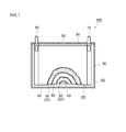
- FIG. 1 is a longitudinal cross-sectional view schematically showing a cross-sectional structure of a nonaqueous electrolyte secondary battery according to an embodiment.
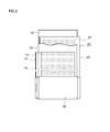
- FIG. 2 is a schematic diagram illustrating a configuration of a wound electrode body according to an embodiment.
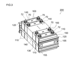
- FIG. 3 is a perspective view schematically showing an assembled battery in which a plurality of nonaqueous electrolyte secondary batteries (unit cells) according to an embodiment are combined.
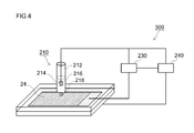
- FIG. 4 is a schematic diagram for explaining a resistance measuring method according to an embodiment.
- FIG. 5 is a graph showing a distribution of resistance values of the negative electrode active material layer according to an example.
- FIG. 6 is a graph showing the relationship between the standard deviation ⁇ of the resistance value, the capacity retention rate of the battery, and the negative electrode heat generation amount.
- a nonaqueous electrolyte secondary battery includes an electrode body formed by laminating a positive electrode and a negative electrode via a separator, and a non-aqueous electrolyte.
- an electrode body wound in a flat shape a wound electrode body
- the present invention will be described in detail by taking as an example a non-aqueous electrolyte secondary battery in which the non-aqueous electrolyte is accommodated in a flat rectangular parallelepiped container (battery case).
- FIG. 1 shows a schematic configuration of a nonaqueous electrolyte secondary battery according to an embodiment of the present invention.
- FIG. 1 is a longitudinal sectional view schematically showing a sectional structure of a nonaqueous electrolyte secondary battery 100.
- a long positive electrode sheet 10 and a long negative electrode sheet 20 are wound flatly via a long separator sheet 40.
- the electrode body (wound electrode body) 80 and the non-aqueous electrolyte (not shown) are accommodated in a battery case 50 having a shape (flat box shape) that can accommodate the wound electrode body.
- the battery case 50 includes a flat rectangular parallelepiped (box-shaped) battery case main body 52 having an open upper end, and a lid 54 that closes the opening.
- a positive terminal 70 for external connection that is electrically connected to the positive electrode of the wound electrode body 80 and a negative electrode that is electrically connected to the negative electrode of the wound electrode body 80.
- a terminal 72 is provided.
- the lid 54 is also provided with a safety valve 55 for discharging the gas generated inside the battery case 50 to the outside of the battery case 50 as in the case of the battery case of the conventional nonaqueous electrolyte secondary battery. .
- the material of the battery case 50 examples include metal materials such as aluminum and steel; resin materials such as polyphenylene sulfide resin and polyimide resin.
- relatively light metals for example, aluminum and aluminum alloys
- the shape of the case is a rectangular parallelepiped shape here, for example, a circular shape (cylindrical shape, coin shape, button shape), hexahedral shape (rectangular shape, cubic shape), bag shape, and The shape etc. which processed and deformed them can also be employ
- FIG. 2 is a schematic diagram showing a configuration of the wound electrode body 80 shown in FIG.
- the wound electrode body 80 includes a long sheet-like positive electrode (positive electrode sheet) 10 and a long sheet-like negative electrode (negative electrode sheet) 20 before assembly.
- the positive electrode sheet 10 includes a long positive electrode current collector 12 and a positive electrode active material layer 14 formed on at least one surface (typically both surfaces) along the longitudinal direction.
- the negative electrode sheet 20 includes a long negative electrode current collector 22 and a negative electrode active material layer 24 formed on at least one surface (typically both surfaces) along the longitudinal direction.
- a separator 40 that prevents direct contact between the positive electrode active material layer 14 and the negative electrode active material layer 24 is disposed.
- two long sheet-like separators 40 are used.
- Such a wound electrode body 80 is obtained by, for example, winding a laminated body in which the positive electrode sheet 10, the separator sheet 40, the negative electrode sheet 20, and the separator sheet 40 are stacked in this order in the longitudinal direction, It can be produced by forming into a flat shape by pressing and curling.
- the central portion is formed on the surface of the positive electrode current collector 12.
- a wound core portion is formed in which the positive electrode active material layer 14 and the negative electrode active material layer 24 formed on the surface of the negative electrode current collector 22 are overlapped and densely stacked. Further, at both ends of the wound electrode body 80 in the winding axis direction, the positive electrode active material layer non-formed portion of the positive electrode sheet 10 and the negative electrode sheet 20 and the negative electrode active material layer non-formed portion are respectively outward from the wound core portion. It sticks out.
- a positive electrode current collector plate is attached to the positive electrode side protruding portion, and a negative electrode current collector plate is attached to the negative electrode side protruding portion, which are electrically connected to the positive electrode terminal 70 (FIG. 1) and the negative electrode terminal 72 (FIG. 1). It is connected.
- the positive electrode sheet 10 includes a positive electrode current collector 12 and a positive electrode active material layer 14 including at least a positive electrode active material formed on the positive electrode current collector.
- a conductive member made of a metal having good conductivity for example, aluminum, nickel, titanium, stainless steel, or the like.
- the positive electrode active material layer 14 includes at least a positive electrode active material.
- a positive electrode active material one or more of various materials known to be usable as a positive electrode active material of a non-aqueous electrolyte secondary battery can be used without particular limitation.
- Preferable examples include layered and spinel-based lithium composite metal oxides (for example, LiNiO 2 , LiCoO 2 , LiFeO 2 , LiMn 2 O 4 , LiNi 0.5 Mn 1.5 O 4 , LiCrMnO 4 ) and olivine systems. (For example, LiFePO 4 ).
- a lithium nickel cobalt manganese composite oxide for example, LiNi 1/3 Co 1/3 Mn having a layered structure containing Li, Ni, Co, and Mn (typically a layered rock salt structure belonging to a hexagonal system). 1/3 O 2 ) can be suitably used.
- a lithium nickel cobalt manganese composite oxide is an oxide containing only Li, Ni, Co and Mn as constituent metal elements, and at least one other metal element in addition to Li, Ni, Co and Mn ( That is, it is meant to include oxides containing transition metal elements and / or typical metal elements other than Li, Ni, Co and Mn.
- Such metal elements include magnesium (Mg), calcium (Ca), strontium (Sr), titanium (Ti), zirconium (Zr), vanadium (V), niobium (Nb), chromium (Cr), molybdenum (Mo), Tungsten (W), iron (Fe), rhodium (Rh), palladium (Pb), platinum (Pt), copper (Cu), zinc (Zn), boron (B), aluminum (Al), gallium (Ga), It may be one or more elements of indium (In), tin (Sn), lanthanum (La), and cerium (Ce).
- the addition amount (blending amount) of these metal elements is not particularly limited, but is usually 0.01 to 5% by mass (eg 0.05 to 2% by mass, typically 0.1 to 0.8% by mass). possible. By setting the amount within the above range, excellent battery characteristics (for example, high energy density) can be realized.
- a general formula: LiMn 2 ⁇ p M p O 4 (wherein p is 0 ⁇ p ⁇ 2 and typically 0 ⁇ p ⁇ 1 (for example, 0.2 ⁇ p ⁇ 0.6)), and a lithium transition metal composite oxide having a spinel structure.
- M can be any metallic or non-metallic element other than Mn.
- a composition in which M contains at least one transition metal element (for example, one or more selected from Ti, Cr, Fe, Co, Ni, Cu and Zn) is preferable.
- the working potential of the positive electrode is about 4.5 V or higher (and moreover 4.4 higher than that of a general non-aqueous electrolyte secondary battery (the upper limit of the working potential is about 4.1 to 4.2 V)). 6V or more, for example, 4.7V or more). Therefore, a much higher energy density can be realized.
- the positive electrode active material layer 14 may be made of one or more materials that can be used as a constituent component of the positive electrode active material layer 14 in a general non-aqueous electrolyte secondary battery as necessary. May be contained.
- a material include a conductive material and a binder.
- the conductive material for example, carbon materials such as various carbon blacks (typically acetylene black and ketjen black), coke, activated carbon, graphite, carbon fiber, and carbon nanotube can be suitably used.
- the binder for example, a vinyl halide resin such as polyvinylidene fluoride (PVdF); a polyalkylene oxide such as polyethylene oxide (PEO); and the like can be preferably used.
- the proportion of the positive electrode active material in the entire positive electrode active material layer 14 is suitably about 60% by mass or more (typically 60 to 99% by mass), and usually about 70 to 95% by mass. Is preferred.
- the proportion of the conductive material in the entire positive electrode active material layer 14 can be, for example, approximately 2 to 20% by mass, and is preferably approximately 3 to 10% by mass.
- the ratio of the binder to the entire positive electrode active material layer 14 can be, for example, about 0.5 to 10% by mass, and is usually preferably about 1 to 5% by mass.
- the mass (weight per unit area) of the positive electrode active material layer 14 provided per unit area of the positive electrode current collector 12 is 3 mg / cm 2 or more per side of the positive electrode current collector 12 from the viewpoint of securing a sufficient battery capacity (for example, 5 mg / cm 2 or more, typically 10 mg / cm 2 or more). Further, from the viewpoint of securing input / output characteristics, the positive electrode current collector 12 may be 50 mg / cm 2 or less per side (for example, 40 mg / cm 2 or less, typically 20 mg / cm 2 or less). In the configuration having the positive electrode active material layer 14 on both surfaces of the positive electrode current collector 12 as in this embodiment, the mass of the positive electrode active material layer 14 provided on each surface of the positive electrode current collector 12 is approximately the same. It is preferable to do.
- the average thickness per one side of the positive electrode active material layer 14 is, for example, 40 ⁇ m or more (typically 50 ⁇ m or more), and may be 100 ⁇ m or less (typically 80 ⁇ m or less).
- the density of the positive electrode active material layer 14 is preferably 1 to 4 g / cm 3 (for example, 1.5 to 3.5 g / cm 3 ).
- the porosity of the positive electrode active material layer 14 may be set to, for example, 10 to 50% by volume (typically 20 to 40% by volume). When one or more of the above properties are satisfied, an appropriate void can be maintained in the positive electrode active material layer 14, and the nonaqueous electrolyte can be sufficiently infiltrated.
- the electroconductivity in the positive electrode active material layer 14 can be kept favorable, and an increase in resistance can be suppressed. Furthermore, the mechanical strength (shape retention) of the positive electrode active material layer 14 can be ensured, and better cycle characteristics can be exhibited.
- the "porosity" as used herein multiplied by 100 and divided by the apparent volume of the total pore volume (cm 3)
- the active material layer obtained by the above measurement of a mercury porosimeter (cm 3) Value.
- the apparent volume can be calculated by the product of the area (cm 2 ) and the thickness (cm) in plan view.
- a method for producing such a positive electrode sheet 10 is not particularly limited. For example, first, a positive electrode active material and a material used as necessary are dispersed in an appropriate solvent, and a paste-like or slurry-like composition (positive electrode) Active material layer forming slurry) is prepared. Next, the prepared positive electrode active material layer forming slurry is applied to the elongated positive electrode current collector 12, and the solvent contained in the slurry is removed. Thereby, the positive electrode sheet 10 provided with the positive electrode active material layer 14 on the positive electrode current collector 12 can be produced.
- the solvent any of an aqueous solvent and an organic solvent can be used. For example, N-methyl-2-pyrrolidone (NMP) can be used.
- the operation of applying the slurry can be performed using an appropriate coating apparatus such as a gravure coater, a slit coater, a die coater, a comma coater, or a dip coater.
- an appropriate coating apparatus such as a gravure coater, a slit coater, a die coater, a comma coater, or a dip coater.
- the removal of the solvent can also be performed by conventional general means (for example, heat drying or vacuum drying).
- the property (namely, average thickness, density, porosity) of the positive electrode active material layer 14 as described above is, for example, that the positive electrode sheet 10 is appropriately pressed after the positive electrode active material layer 14 is formed. Can be adjusted by.
- Various conventionally known press methods such as a roll press method and a flat plate press method can be employed for the press treatment. Further, such processing may be performed once or may be performed two or more times.
- the negative electrode sheet 20 includes a negative electrode current collector 22 and a negative electrode active material layer 24 including at least a negative electrode active material formed on the negative electrode current collector.
- a conductive material made of a metal having good conductivity for example, copper, nickel, titanium, stainless steel, etc.
- the negative electrode active material layer 24 includes at least a negative electrode active material.
- the negative electrode active material one or more of various materials known to be usable as a negative electrode active material for a non-aqueous electrolyte secondary battery can be used without particular limitation.
- Preferable examples include carbon materials such as graphite (graphite), non-graphitizable carbon (hard carbon), graphitizable carbon (soft carbon), and carbon nanotubes.
- graphite-type materials especially natural graphite
- natural graphite such as natural graphite and artificial graphite
- a battery including a graphite-based material in a negative electrode In general, in a battery including a graphite-based material in a negative electrode, components (for example, non-aqueous) contained in a non-aqueous electrolyte solution when charging / discharging is repeated under severe conditions (for example, high temperature environment and / or high input / output density). Solvent and supporting salt) are gradually decomposed, and the energy density may be lowered.
- solvent and supporting salt are gradually decomposed, and the energy density may be lowered.
- a suitable coating derived from the BP-oxalato compound is formed on the surface of the negative electrode active material, such decomposition hardly occurs and a high energy density can be realized over a long period of time. .
- a negative electrode active material may be a particle form or a powder form.
- the average particle size of the particulate negative electrode active material may be 20 ⁇ m or less (typically 1 to 20 ⁇ m, for example, 5 to 15 ⁇ m).
- the specific surface area is 1 m 2 / g or more (typically 2.5 m 2 / g or more, for example, 2.8 m 2 / g or more), and 10 m 2 / g or less (typically 3.5 m 2 / G or less, for example 3.4 m 2 / g or less).
- a negative electrode active material satisfying one or two of the above properties can ensure a wide charge carrier reaction field even when a coating film derived from a BP-oxalato compound is formed on the surface, and a higher battery. Characteristics (for example, high input / output characteristics) can be realized.
- the “average particle size” means particles corresponding to 50% cumulative from the fine particle side in the volume-based particle size distribution measured by particle size distribution measurement based on a general laser diffraction / light scattering method.
- diameter (D 50 particle size, also called median diameter.) refers to.
- BET specific surface area (m 2 / g) means a gas adsorption amount measured by a gas adsorption method (fixed capacity adsorption method) using nitrogen (N 2 ) gas as an adsorbate. The value calculated by analyzing by the BET method (for example, the BET 1-point method).
- the negative electrode active material layer 24 is made of one or more materials that can be used as a constituent component of the negative electrode active material layer in a general non-aqueous electrolyte secondary battery as necessary. May be contained.
- materials include binders and various additives.
- the binder for example, a polymer material such as styrene butadiene rubber (SBR), polyvinylidene fluoride (PVdF), polytetrafluoroethylene (PTFE), or the like can be suitably used.
- various additives such as a thickener, a dispersant, and a conductive material can be appropriately used.
- CMC carboxymethylcellulose
- MC methylcellulose
- the proportion of the negative electrode active material in the whole negative electrode active material layer 24 is suitably about 50% by mass or more, and preferably 90 to 99% by mass (for example, 95 to 99% by mass).
- the ratio of the binder to the whole negative electrode active material layer 24 can be, for example, about 1 to 10% by mass, and usually about 1 to 5% by mass.
- the proportion of the thickener in the negative electrode active material layer 24 as a whole can be, for example, about 1 to 10% by mass, and usually about 1 to 5% by mass. .
- the mass (weight per unit area) of the negative electrode active material layer 24 provided per unit area of the negative electrode current collector 22 is 3 mg / cm 2 or more per side of the negative electrode current collector 22 from the viewpoint of securing sufficient battery capacity (typically Specifically, it is preferable to set it to 5 mg / cm 2 or more, for example, 7 mg / cm 2 or more. Further, from the viewpoint of securing input / output characteristics, the negative electrode current collector 22 may be 30 mg / cm 2 or less (typically 20 mg / cm 2 or less, for example, 15 mg / cm 2 or less) per one surface. In the configuration having the negative electrode active material layer 24 on both surfaces of the negative electrode current collector 22 as in this embodiment, the mass of the negative electrode active material layer 24 provided on each surface of the negative electrode current collector 22 is approximately the same. It is preferable to do.
- the thickness per one side of the negative electrode active material layer 24 is, for example, 40 ⁇ m or more (preferably 50 ⁇ m or more) and 100 ⁇ m or less (preferably 80 ⁇ m or less). Further, the density of the negative electrode active material layer 24 may be, for example, about 0.5 to 2 g / cm 3 (preferably 1 to 1.5 g / cm 3 ). Further, the porosity of the negative electrode active material layer 24 may be, for example, about 5 to 50% by volume (preferably 35 to 50% by volume). When one or more of the above properties are satisfied, a higher energy density can be realized. Moreover, a moderate space
- a method for producing such a negative electrode sheet 20 is not particularly limited. For example, first, a negative electrode active material and a material used as necessary are dispersed in an appropriate solvent, and a paste-like or slurry-like composition (negative electrode Active material layer forming slurry) is prepared. And the prepared slurry for negative electrode active material layer formation is provided to the elongate negative electrode collector 22, and the solvent contained in this slurry is removed. Thereby, the negative electrode sheet 20 provided with the negative electrode active material layer 24 on the negative electrode current collector 22 can be produced.
- the solvent any of an aqueous solvent and an organic solvent can be used. For example, water can be used.
- the properties (porosity, thickness, density) of the negative electrode active material layer 24 can be adjusted by performing an appropriate press treatment in the same manner as the positive electrode active material layer 14 described above.
- a film substantially derived from the BP-oxalato compound is formed on the negative electrode active material layer 24 (specifically, the surface of the negative electrode active material).
- Such coatings typically include boron (B) and / or phosphorus (P) atoms, oxalate ions (C 2 O 4 2 ⁇ ), and charge carrier ions (eg, Li + ). .
- it may be in the form of LiBO 2 F, LiBO 3 , LiPO 2 F 2 , LiPO 3 F, LiPO 4 or the like.
- This coating stabilizes the interface between the negative electrode active material (typically a graphite material) and the non-aqueous electrolyte, so that the decomposition of the non-aqueous electrolyte during the subsequent charge / discharge can be suppressed.
- “substantially” is an expression used for the main constituent components of the film containing boron atoms and / or phosphorus atoms, and typically 80 mol% or more (preferably 85 mol% or more) of the film. , More preferably 90 mol% or more) is derived from a BP-oxalato compound.
- the coating film contains components derived from components other than the BP-oxalato compound, such as decomposition products of other components constituting the non-aqueous electrolyte (specifically, supporting salts and non-aqueous solvents). It can be tolerated.
- the qualitative and quantitative determination of the coating film formed on the surface of the negative electrode active material can be measured by, for example, a general ion chromatography (IC) method.
- the battery is first disassembled, the negative electrode (negative electrode active material layer) is taken out, immersed in an appropriate solvent (for example, EMC), washed, cut into a predetermined size, and used as a measurement sample.
- an appropriate solvent for example, EMC
- the coating component ion derived from the BP-oxalato compound
- BP ⁇ contained per unit area (1 cm 2 )
- the coating amount ( ⁇ M / cm 2 ) derived from the oxalato compound can be determined.
- the coating film on the surface of the negative electrode active material As a method for qualitatively and quantitatively determining the coating film on the surface of the negative electrode active material, the case where ion chromatography is used is specifically shown above. However, the method is not limited to this. The same analysis can be performed by (ICP-AES: Inductively Coupled Plasma-Atomic Emission Spectrometry), X-ray Absorption Fine Structure (XAFS) and the like.
- ICP-AES Inductively Coupled Plasma-Atomic Emission Spectrometry
- XAFS X-ray Absorption Fine Structure
- the technique disclosed herein is characterized in that the resistance value of the negative electrode active material layer is within a predetermined range. That is, for at least a part of the negative electrode active material layer, the resistance value measured at a plurality of points at equal intervals in the line direction from the predetermined laminated surface of the electrode body to the other laminated surface opposite to the linear direction.
- the standard deviation ⁇ is 3.0 or more and 7.2 or less. By setting the standard deviation ⁇ within the range, it is possible to achieve a battery performance that is excellent during normal use and that is also excellent in tolerance during overcharge. In a preferred embodiment, the standard deviation ⁇ is 3.0 or more and 5.0 or less. Thereby, the battery performance which was more excellent at the time of normal use can be exhibited, and the effect of the present invention can be exhibited at a higher level.
- the standard deviation ⁇ of the resistance value is, for example, the following process: a preparation step of the negative electrode active material layer (measurement object); a measurement point setting process; a resistance value measurement process at the measurement point; a standard deviation ⁇ calculation process; It can obtain
- the battery is disassembled and the negative electrode active material layer (typically, the negative electrode having the negative electrode active material layer supported on the surface of the negative electrode current collector) is taken out and an appropriate solvent (for example, And a nonaqueous solvent described later).
- the measurement point reaches from the predetermined one end (predetermined one laminated surface in the state of the electrode body) to another one end (the opposite laminated surface) in the linear direction.
- a plurality are set at equal intervals in the line direction.
- the measurement point is preferably set so as to include the vicinity of the central portion (central portion) of the negative electrode active material layer.
- the negative electrode active material layer 24 of the inner flat portion excluding at least the outermost periphery, which is the negative electrode active material layer 24 constituting the wound electrode body.
- the negative electrode active material layer constituting the laminated electrode body in which the substantially square positive electrode and negative electrode are laminated a plurality of the negative electrode active material layers at equal intervals in the line direction from one corner to the other corner in a diagonal line. It is preferable to set the measured points. There may be a plurality of points to be measured, that is, two or more points. Typically, the points to be measured are odd points that are set at equal intervals in a line shape including the vicinity of the center.
- the point to be measured is usually preferably 5 points or more, and typically 7 points or more, for example, 11 points or more. Further, from the viewpoint of work efficiency, it is preferably 31 points or less, for example, 25 points or less.
- the resistance measuring apparatus 300 shown in FIG. 4 includes a Lugin tube type counter electrode 210, an AC impedance measuring unit 230, and a control unit 240.
- the Lugin tube-type counter electrode 210 includes a Lugin tube main body 212 and a measurement unit 218 connected to the main body.
- the measurement unit 218 is a part that is brought into contact with the measurement point of the negative electrode active material layer 24 through a nonaqueous electrolytic solution.
- the cross-sectional area (contact area with the negative electrode active material layer 24) of the end of the measurement unit is generally 0.01 to 0.1 cm 2 (typically 0.02 to 0). About 0.05 cm 2 ).
- the shape of the edge part of the measurement part 218 is circular.
- the lugin tube body 212 is preferably made of a material having the above-mentioned end shape and excellent in chemical resistance.
- the Lugin tube body 212 has a predetermined non-aqueous electrolyte 216 and a counter electrode 214 disposed in the non-aqueous electrolyte.
- the non-aqueous electrolyte 216 the same non-aqueous electrolyte secondary battery can be used.
- the counter electrode 214 for example, the above-described positive electrode or negative electrode can be used.
- the area of the counter electrode 214 is 100 times or more (typically 200 times or more, preferably 300 times or more, more preferably 500 times or more) than the area of the end of the measurement unit 218 (contact area with the negative electrode active material layer 24). ) It is preferable to set wide. As a result, the reaction resistance of the counter electrode 214 can be made negligibly small. More specifically, for example, the resistance of the counter electrode 214 can be set to about 1/50 or less (preferably 1/100 or less) of the inspection target (measurement point). Therefore, the resistance derived from the coating formed on the negative electrode active material layer 24 can be accurately measured.
- an electrode that is rolled up as a counter electrode 214 is accommodated in the Lugin tube body 212.
- the AC impedance measuring unit 230 electrically connects the counter electrode 214 and the measurement point of the negative electrode active material layer 24.
- the AC impedance measuring unit 230 can be arbitrarily selected from those conventionally used as a general impedance measuring device. For example, a Solartron 1287 type potentio / galvanostat and a 1255B type frequency response analyzer can be used in combination.
- the control unit 240 controls measurement of AC impedance, adjustment of the Lugin tube type counter electrode 210, and the like based on predetermined information.
- the resistance value can be measured by using the resistance inspection apparatus 300 according to the following procedures (1) to (4).
- (Procedure 1) A Lugin tube type counter electrode as described above is prepared.
- (Procedure 2) The measurement part of the Lugin tube type counter electrode is brought into contact with the measurement point of the negative electrode active material layer, and the counter electrode and the measurement point of the negative electrode active material layer are electrically connected via the non-aqueous electrolyte. Connect to.
- (Procedure 3) An alternating current or an alternating voltage is input between the electrically connected counter electrode and the measurement point to measure impedance.
- (Procedure 4) A resistance value is calculated based on the measurement result of the impedance.
- the frequency region for measuring impedance may be set to, for example, about 100 kHz to 0.01 Hz (typically 10 kHz to 0.1 Hz, for example, 1 kHz to 0.1 Hz) from the viewpoint of measurement accuracy, measurement time, and the like. it can.
- the input voltage can be set to about 100 to 1000 mV (typically 200 to 1000 mV, for example, 300 to 1000 mV).
- the resistance value can be easily calculated by subtracting the value of the intersection point intersecting the real axis on the high frequency side from the value of the intersection point intersecting the real axis on the low frequency side of the Cole-Cole plot, for example. Alternatively, it can be obtained by analyzing the shape of the Cole-Cole plot in comparison with an appropriately selected equivalent circuit (by curve fitting). Then, a statistical standard deviation ⁇ is calculated based on the resistance value at each measurement point.
- the separator sheet 40 interposed between the positive and negative electrode sheets 10 and 20 may be any sheet as long as it insulates the positive electrode active material layer 14 and the negative electrode active material layer 24 and has a nonaqueous electrolyte holding function and a shutdown function.
- Preferable examples include porous resin sheets (films) made of a resin such as polyethylene (PE), polypropylene (PP), polyester, cellulose, and polyamide.
- a porous resin sheet may have a single-layer structure or a laminated structure of two or more layers (for example, a three-layer structure in which PP layers are laminated on both sides of a PE layer).
- the average thickness of the porous resin sheet is preferably about 10 to 40 ⁇ m, for example.
- the separator sheet 40 may be configured to include a porous heat-resistant layer on one side or both sides (typically, one side) of the porous resin sheet.
- a porous heat-resistant layer can be, for example, a layer containing an inorganic material (inorganic fillers such as alumina particles can be preferably employed) and a binder.
- it may be a layer containing insulating resin particles (for example, particles of polyethylene, polypropylene, etc.).
- the nonaqueous electrolytic solution contains at least a supporting salt in a nonaqueous solvent.
- the non-aqueous electrolyte is in a liquid state at normal temperature (for example, 25 ° C.). In a preferred embodiment, the non-aqueous electrolyte is always in a liquid state in the battery use environment (for example, in a temperature environment of ⁇ 30 to 60 ° C.).
- non-aqueous solvent organic solvents such as various carbonates, ethers, esters, nitriles, sulfones, and lactones used in the electrolyte of general non-aqueous electrolyte secondary batteries can be used.
- organic solvents such as various carbonates, ethers, esters, nitriles, sulfones, and lactones used in the electrolyte of general non-aqueous electrolyte secondary batteries
- EC ethylene carbonate
- PC propylene carbonate
- DEC diethyl carbonate
- DMC dimethyl carbonate
- EMC ethyl methyl carbonate
- Such a non-aqueous solvent can be used individually by 1 type or in combination of 2 or more types as appropriate.
- a high dielectric constant solvent and a low viscosity solvent are mixed and used.
- the high dielectric constant solvent examples include EC
- examples of the low viscosity solvent examples include DMC and EMC.
- one or more carbonates are included, and the total volume of these carbonates is 60% by volume or more (more preferably 75% by volume or more, more preferably 90% by volume or more) of the total volume of the nonaqueous solvent.
- the non-aqueous solvent occupying 100% by volume may be preferably used.
- ethylene carbonate accounts for 20 volume% or more and 40 volume% or less of the entire non-aqueous solvent.
- the supporting salt is the same as that of a general non-aqueous electrolyte secondary battery as long as it contains a charge carrier (for example, lithium ion, sodium ion, magnesium ion, etc., lithium ion in a lithium ion secondary battery).
- a charge carrier for example, lithium ion, sodium ion, magnesium ion, etc., lithium ion in a lithium ion secondary battery.
- the charge carrier is lithium ion
- lithium salts such as LiPF 6 , LiBF 4 , LiClO 4 , LiAsF 6 , Li (CF 3 SO 2 ) 2 N, LiCF 3 SO 3 are exemplified.
- Such a supporting salt can be used singly or in combination of two or more.
- LiPF 6 may be mentioned as particularly preferred support salt.
- the non-aqueous electrolyte is preferably prepared so that the concentration of the supporting salt is within the range of 0.7 to 1.3 mol / L.
- the non-aqueous electrolyte contains a BP-oxalato compound at least in the state of the battery assembly (the state before the charging process).
- the compound is reduced and decomposed at the negative electrode by the charging process (typically, the first charging process), and is bonded (attached) to the surface of the negative electrode active material as a high-quality film. Therefore, it is not always necessary that the compound remains in the non-aqueous electrolyte after the initial charging process.
- the non-aqueous electrolyte may further contain various additives as long as the effects of the present invention are not significantly impaired.
- additives include film forming materials other than BP-oxalato compounds (for example, vinylene carbonate, vinyl ethylene carbonate, fluoroethylene carbonate), compounds that can generate gas upon polymerization when overcharged (for example, biphenyl, cyclohexylbenzene). ), Various dispersants and thickeners.
- the nonaqueous electrolyte secondary battery as described above can be suitably manufactured by a manufacturing method including the following steps, for example.
- Preparation step preparing an electrode body and a non-aqueous electrolyte.
- Construction process housing the electrode body and the non-aqueous electrolyte in a battery case to construct a battery assembly.
- Holding step holding the battery assembly constructed above in a temperature range lower than 25 ° C. for a predetermined time.
- Charging process step performing a charging process between the positive electrode and the negative electrode.
- a suitable film that is, a film having a standard deviation ⁇ of resistance value of 3.0 to 7.2
- each process is demonstrated in order.
- an electrode body and a non-aqueous electrolyte are prepared.
- the electrode body has a configuration in which a positive electrode having a positive electrode active material layer and a negative electrode having a negative electrode active material layer are laminated via a separator.
- As the positive electrode, the negative electrode, and the separator constituting the electrode body those already described above can be used.
- the nonaqueous electrolytic solution typically includes a nonaqueous solvent, a supporting salt, and a BP-oxalato compound. As the non-aqueous solvent and the supporting salt, those already described above can be used.
- the BP-oxalato compound one produced by a known method or one obtained by purchasing a commercially available product is not particularly limited, and one or more kinds can be used.
- at least one oxalate ion (C 2 O 4 2 ⁇ ) is coordinated to a boron (B) atom as a central atom.
- An oxalato complex compound (B atom-containing oxalate salt) having a structural moiety can be used.
- Such a compound can be reduced and decomposed at the negative electrode during the charging process (typically, the first charging process), and can adhere (bond) to the surface of the negative electrode active material as a high-quality film having low resistance and excellent stability. .
- a + in formulas (V) and (VI) may be either an inorganic cation or an organic cation.
- inorganic cations include alkali metal cations such as Li, Na, and K; alkaline earth metal cations such as Be, Mg, and Ca; other, Ag, Zn, Cu, Co, Fe, Ni, Mn, and Ti , Pb, Cr, V, Ru, Y, metal cations such as lanthanoids, actinoids, protons, and the like.
- organic cations include tetraalkylammonium ions such as tetrabutylammonium ion, tetraethylammonium ion and tetramethylammonium ion; trialkylammonium ions such as triethylmethylammonium ion and triethylammonium ion; other pyridinium ions and imidazolium ions Tetraethylphosphonium ion, tetramethylphosphonium ion, tetraphenylphosphonium ion, triphenylsulfonium ion, triethylsulfonium ion; and the like.
- tetraalkylammonium ions such as tetrabutylammonium ion, tetraethylammonium ion and tetramethylammonium ion
- trialkylammonium ions such as triethyl
- R 1 and R 2 are each independently a halogen atom of F, Cl, Br, etc. (preferably F); a par atom having 1 to 10 carbon atoms (preferably 1 to 3 carbon atoms).
- oxalato complex compound examples include lithium bis (oxalato) borate (LIBOB) represented by the above formula (I); lithium difluorooxalate borate (LBFO) represented by the above formula (II); Is mentioned.
- LIBOB lithium bis (oxalato) borate
- LBFO lithium difluorooxalate borate
- At least one oxalate ion (C 2 O 4 2 ⁇ ) as represented by the above formulas (III) and (IV) is coordinated to a phosphorus (P) atom as a central atom.
- an oxalato complex compound (P atom-containing oxalate salt) having a six-coordinate structural moiety.
- the cation is a lithium ion
- other cations may be used in the same manner as A + in the formulas (V) and (VI).
- F in the above formulas (III) and (IV) is independently F and other halogen atoms (for example, Cl and Br, preferably F) as in R 1 and R 2 in the formula (V).
- oxalato complex compound examples include lithium difluorobis (oxalate) phosphate (LPFO) represented by the above formula (III); lithium tetrafluorooxalate phosphate represented by the above formula (IV); lithium tris. (Oxalato) phosphate; and the like.
- the reduction potential (vs. Li / Li + ) of the BP-oxalato compound is higher than other components (typically non-aqueous solvents) contained in the non-aqueous electrolyte. That is, an embodiment in which the reduction potential of the BP-oxalato compound is the highest among the components contained in the nonaqueous electrolytic solution is preferable.
- the reduction potential of LIBOB is approximately 1.73V (vs. Li / Li + )
- Li / Li + generally It is preferably equal or lower (typically lower than 0.1V, for example lower than 0.5V, especially lower than 0.8V).
- a film derived from the BP-oxalato compound can be suitably formed on the surface of the negative electrode active material.
- the amount of BP-oxalato compound added may vary depending on, for example, the type and properties of the negative electrode active material (eg, particle size and specific surface area). In general, the smaller the average particle size and / or the larger the BET specific surface area, the more the suitable amount of BP-oxalato compound added tends to increase. For this reason, although not particularly limited, when the addition amount is too small, the film formed on the surface of the negative electrode active material becomes thin, and the durability (storage characteristics and rapid charge / discharge characteristics) of the battery may be reduced. On the other hand, when the addition amount is too large, the film formed on the surface of the negative electrode active material becomes thick, and there is a concern that the resistance accompanying charge / discharge increases.
- the addition amount is too small, the film formed on the surface of the negative electrode active material becomes thin, and the durability (storage characteristics and rapid charge / discharge characteristics) of the battery may be reduced.
- the addition amount is too large, the film formed on the surface of the negative electrode active material becomes thick,
- the concentration of the BP-oxalato compound in the non-aqueous electrolyte is 0.005 mol / L or more (for example, 0.01 mol / L or more) with respect to the non-aqueous electrolyte, .2 mol / L or less (for example, 0.1 mol / L or less, preferably 0.07 mol / L or less).
- the addition amount is in the above range, the effect of the present invention can be exhibited at a higher level.
- Such a nonaqueous electrolytic solution can be typically prepared by uniformly dissolving a supporting salt and a BP-oxalato compound in a nonaqueous solvent.
- a BP-oxalato compound is directly added and impregnated into the electrode body (typically, the negative electrode active material layer or the separator) as described above, and the electrode body and a nonaqueous solvent containing only the supporting salt are added.
- the BP-oxalato compound can be eluted in the non-aqueous electrolyte by being housed in the battery case.
- the amount of the BP-oxalato compound used in the construction of the battery is, for example, positive and negative electrode active material by the above-described ion chromatography technique. Quantifying the coating derived from the compound contained in the layer; analyzing the non-aqueous electrolyte accumulated in the battery case by ion chromatography and quantifying the BP-oxalato compounds and chemical species derived from their decomposition products It can be generally grasped by the method of doing;
- the electrode body and the non-aqueous electrolyte are accommodated in a battery case.
- a battery case typically, first, an electrode body is accommodated in a battery case, and the inside of the battery case is depressurized to about -70 to -90 kPa.
- the non-aqueous electrolyte can penetrate into the electrode body.
- a non-aqueous electrolyte secondary battery assembly can be constructed by sealing the opening of the battery case by welding or the like.
- the pressure inside the battery assembly immediately after construction is almost equal to the atmospheric pressure.
- ⁇ (3) Holding step> the battery assembly constructed as described above is held (leaved) for a predetermined time in a temperature range lower than 25 ° C.
- the nonaqueous electrolytic solution containing the BP-oxalato compound is suitably distributed over the entire electrode body, and the concentration of the BP-oxalato compound is appropriately homogenized in the electrode body.
- the “temperature range lower than 25 ° C.” is typically lower than 20 ° C., for example, 18 ° C. or lower, preferably 15 ° C. or lower.
- the lower limit of the temperature is not particularly limited because it depends on, for example, the properties of the negative electrode (the density and thickness of the negative electrode active material layer) and the retention time of this step, but typically 5 ° C. from the viewpoint of work efficiency and cost. It can be higher, for example, 7 ° C. or higher, preferably 8 ° C. or higher, more preferably 10 ° C. or higher.
- the holding time in the low temperature range is not particularly limited because it depends on, for example, the properties of the negative electrode (the density and thickness of the negative electrode active material layer), the holding temperature in this step, and the like. It is preferably about 5 to 20 hours (for example, 10 to 16 hours).
- ⁇ (4) Charging process> a charging process is performed between the positive electrode and the negative electrode.
- the BP-oxalato compound is reduced and decomposed at the negative electrode, and a suitable film (that is, a film having a resistance standard deviation ⁇ of 3.0 to 7.2) is formed on the surface of the negative electrode active material.
- Such charging treatment is performed so that the potential of the negative electrode (vs. Li / Li + ) is lower than the reduction potential of the BP-oxalato compound contained in the non-aqueous electrolyte.
- the charge treatment is carried out until it is 0.05 V or more (typically 0.1 V or more, such as 0.3 V or more, particularly 0.5 V) lower than the reduction potential of the compound contained in the electrolytic solution. I do.
- the voltage between the positive and negative terminals (typically the highest voltage reached) in the charging process varies depending on, for example, the type of the BP-oxalato compound used, but it is 3.9 to 4.2 V (eg, 3.95 to It is good to set it to about 4.15V).
- the charging process may be performed by a constant current charging method (CC charging) from the start of charging until the negative electrode potential reaches a predetermined value (or until the voltage between the positive and negative terminals reaches a predetermined value), After charging with a constant current until the predetermined potential (or voltage) is reached, charging may be performed with a constant voltage (CCCV charging).
- CCCV charging constant voltage
- the charging process is performed by a CCCV charging method.
- the charging rate in CC charging is not particularly limited, but if it is too low, the processing efficiency tends to decrease. On the other hand, if it is too high, the denseness of the formed film may be insufficient, or the positive electrode active material may be deteriorated.
- 0.1 to 2C (typically 0.5 to 1.5C, for example, 0.6 to 1C) is preferable.
- a suitable denseness that is, a low resistance and capable of sufficiently suppressing the reaction with the non-aqueous electrolyte
- the said charge process may be performed once, for example, can also be performed twice or more across a discharge process process.
- other operations that can promote the reductive decomposition of the above compound for example, heating, pressure load, ultrasonic irradiation
- FIG. 3 shows an example of an assembled battery 200 in which nonaqueous electrolyte secondary batteries (unit cells) 100 are connected in series and / or in parallel.
- the battery (single cell) disclosed here is characterized by a higher energy density and output density than conventional batteries. Therefore, an assembled battery formed by connecting a plurality of these single cells to each other (typically in series) can exhibit even higher battery characteristics.
- the assembled battery 200 includes a plurality of (typically 10 or more, preferably about 10 to 30, for example, 20) non-aqueous electrolyte secondary batteries (unit cells) 100, respectively.
- the positive and negative terminals 70 and 72 are inverted one by one so as to be alternately arranged, and the wide surfaces of the battery case are arranged in the facing direction (stacking direction).
- a cooling plate 110 having a predetermined shape is sandwiched between the arranged unit cells 100.
- the cooling plate 110 functions as a heat dissipating member for efficiently dissipating heat generated in each unit cell 100 during use, and preferably a cooling fluid (typically between the unit cells 100). Air) (for example, a shape in which a plurality of parallel grooves extending vertically from one side of the rectangular cooling plate to the opposite side are provided on the surface).
- a cooling plate made of metal having good thermal conductivity or lightweight and hard polypropylene or other synthetic resin is suitable.
- a pair of end plates (restraint plates) 120 are disposed at both ends of the unit cell 100 and the cooling plate 110 arranged as described above.
- One or more sheet-like spacer members 150 as length adjusting means may be sandwiched between the cooling plate 110 and the end plate 120.
- the unit cell 100, the cooling plate 110, and the spacer member 150 arranged in the above manner are applied with a predetermined restraining pressure in the stacking direction by a fastening restraint band 130 attached so as to bridge between both end plates. It is restrained. More specifically, by tightening and fixing the end portion of the restraining band 130 to the end plate 120 with screws 155, the unit cells and the like are restrained so that a predetermined restraining pressure is applied in the arrangement direction.
- the battery disclosed herein can be used for various applications, the effect of adding a BP-oxalato compound is suitably exhibited, and both durability and overcharge resistance can be achieved at a high level. Therefore, taking advantage of such properties, for example, it can be suitably used as a driving power source mounted on a vehicle.
- the type of vehicle is not particularly limited, and examples include plug-in hybrid vehicles (PHV), hybrid vehicles (HV), electric vehicles (EV), electric trucks, motorbikes, electric assist bicycles, electric wheelchairs, electric railways, and the like.
- PUV plug-in hybrid vehicles
- HV hybrid vehicles
- EV electric vehicles
- electric trucks motorbikes
- electric assist bicycles electric wheelchairs
- electric railways electric railways, and the like.
- a vehicle equipped with any of the nonaqueous electrolyte secondary batteries disclosed herein preferably as a power source.
- a non-aqueous electrolyte secondary battery provided in a vehicle is usually in the form of the above assembled battery in which a plurality of single
- LNCM LiNi 1/3 Mn 1/3 Co 1/3 O 2
- AB acetylene black
- PVdF polyvinylidene fluoride
- This slurry is applied to both sides of a 15 ⁇ m thick aluminum foil (positive electrode current collector) with a width of 96 mm, dried and then pressed to form a positive electrode sheet having a positive electrode active material layer on both sides of the positive electrode current collector (total thickness: 170 ⁇ m) Electrode density: 3 g / cm 3 ).
- C natural graphite (C) as a negative electrode active material
- SBR styrene butadiene rubber
- CMC carboxymethyl cellulose
- the slurry was applied to both sides of a long copper foil (negative electrode current collector) having a thickness of 10 ⁇ m with a width of 100 mm, dried and pressed to obtain a negative electrode sheet having a negative electrode active material layer on both sides of the negative electrode current collector (total (Thickness: 150 ⁇ m, electrode density: 1.1 g / cm 3 ).
- the positive electrode sheet and the negative electrode sheet produced above are composed of two separator sheets (here, a three-layer structure in which polypropylene (PP) is laminated on both sides of polyethylene (PE), with a thickness of 20 ⁇ m and a width of 110 mm.
- a flat wound electrode body was produced by pressing and ablating from the side direction.
- the positive electrode terminal and the negative electrode terminal were attached to the lid of the battery case, and these terminals were welded to the positive electrode current collector and the negative electrode current collector exposed at the ends of the wound electrode body, respectively.
- the wound electrode body thus connected to the lid body was housed in the rectangular battery case from the opening, and the opening and the lid were welded.
- the nonaqueous electrolyte was injected from the electrolyte injection hole provided in the lid, and the wound electrode body was impregnated with the nonaqueous electrolyte.
- EC ethylene carbonate
- DMC dimethyl carbonate
- EMC ethyl methyl carbonate
- LiPF 6 was dissolved at a concentration of 1.1 mol / L, and lithium bis (oxalato) borate (LiBOB) as a BP-oxalato compound was dissolved at a concentration of 0.05 mol / L.
- LiBOB lithium bis (oxalato) borate
- the constructed battery assembly was held under the conditions (temperature and time) shown in Table 1, and then the initial charging process was performed in an environment of 25 ° C. Specifically, CC charging was performed until the voltage between the positive and negative terminals reached 4.1 V at a charging rate of 1 C, and then CV charging was performed until the current value reached 0.02 C. As a result, a boron atom-containing film substantially derived from the oxalato complex compound was formed on the surface of the negative electrode active material.
- Example 3 two lithium ion secondary batteries (Example 3) were constructed in the same manner as described above except that the pressure at the time of pressing was adjusted so that the density of the negative electrode active material layer was 1.0 g / cm 3 .
- Lithium deposition test The lithium ion secondary batteries according to Examples 1 to 7 after the rated capacity measurement were subjected to a low-temperature pulse cycle test consisting of a charge pattern and an equivalent discharge pattern simulating the charge current and time generated during vehicle slip grip at low temperatures. It was. Specifically, first, the battery was adjusted to a charged state of SOC 60% in an environment of 25 ° C. The battery was subjected to a rectangular wave cycle test of 6000 cycles in a pulse charge pattern consisting of the following steps 1 and 2 in an environment of 0 ° C. (Step 1) A pulse charge for 10 seconds is performed at a constant current of 20 C and a pause is made for 5 seconds.
- Step 2 A pulse discharge for 10 seconds is performed at a constant current of 20 C, and a pause is made for 5 seconds. Then, the discharge capacity (capacity after the pulse test) was measured under the same conditions as the initial capacity, and the ratio “(battery capacity after the pulse test / initial capacity) ⁇ 100” was calculated. The results are shown in the “capacity maintenance ratio” column of Table 1.
- ohm)) of the said to-be-measured point was measured by the alternating current impedance method using the resistance test
- the specifications of the Lugin tube type counter electrode and the measurement conditions of the AC impedance are as follows.
- Lugin tube type counter electrode Lugin tube body: Terumo syringe Needle-free (made of polypropylene)
- Counter electrode negative electrode sheet (non-charged, negative electrode active material layer area: 30 cm 2 )
- the resistance of each measured part The value (R 1 ( ⁇ )) was calculated.
- the distribution of resistance values ( ⁇ ) of the negative electrode active material layer according to Example 1 is shown in FIG.
- the resistance of the negative electrode active material layer showed a high value at the central portion and the end portion of the electrode, and it was found that more films substantially derived from the oxalato complex compound were formed at such sites.
- the standard deviation of the resistance values measured at 11 points to be measured is obtained, and the result is shown in the column of “standard deviation ⁇ ” in Table 1.
- the resistance value varies (the laminated surface on the opposite side in a linear direction from the predetermined one laminated surface of the electrode body). It was found that the distribution of resistance values in the line direction leading to 2), that is, the uniformity of the formed film was different. For example, comparing the results of Example 1 and Example 2 with a holding time of 16 hours, it was found that the lower the holding temperature, the smaller the resistance unevenness and the smaller the standard deviation ⁇ of the resistance value. This tendency was the same in Examples 4 and 7 in which the retention time was 13 hours, and in Examples 5 and 6 in which the retention time was 10 hours.
- Example 1 comparing the results of Example 1 and Example 7 in which the holding temperature was 15 ° C., it was found that the shorter the holding time, the smaller the resistance unevenness, that is, the smaller the standard deviation ⁇ of the resistance value. This tendency was the same in Example 4 and Example 6 in which the holding temperature was 10 ° C.
- Fig. 6 shows the relationship between the standard deviation ⁇ and the capacity retention rate after the rectangular wave cycle test by the ⁇ mark (black diamond mark).
- the capacity retention ratio was higher as the standard deviation ⁇ of the resistance value was smaller (closer to 0).
- the capacity maintenance ratio can be 89% or more.
- the standard deviation ⁇ of the resistance value is 5.0 or less (for example, 4.4 or less).
- the capacity retention rate could be 91% or more. This is considered to be because the charge / discharge reaction could be caused more uniformly by forming a homogeneous film on the surface of the negative electrode active material.
- the standard deviation ⁇ of the resistance value 7.2 or less (preferably 5.0 or less), excellent battery characteristics (for example, input / output characteristics and cycle characteristics) can be exhibited.
- the standard deviation ⁇ of the resistance value is 10 or more. Therefore, the excellent battery characteristics as described above show the technical significance of the present invention.
- This measurement sample and the above non-aqueous electrolyte solution were set in a DSC apparatus (manufactured by Shimadzu Corporation, model “DSC-60”), and kept at 50 ° C. for 1 hour in a nitrogen atmosphere.
- the measurement was carried out by changing the temperature from 50 ° C. to 350 ° C. at a rate of temperature increase per minute.
- the area from 50 degreeC to 350 degreeC of the obtained DSC curve was made into the total calorific value (J).
- the result is shown in the column of “heat generation amount” in Table 1. Further, in FIG. 6, the relationship between the standard deviation ⁇ and the calorific value is indicated by ⁇ (black circle).
- the calorific value (J) per 18 cm 2 of the negative electrode active material layer is shown here, the calorific value (J) is divided by the area (18 cm 2 ) of the negative electrode active material layer used for the measurement, It can also be set as the calorific value per unit area (J / cm 2 ).
- Example 5 in which the standard deviation ⁇ of the resistance value was as small as 2 or less (that is, a uniform film was formed in the line direction), the calorific value was as large as 470 J / 18 cm 2 . . This may be because the negative electrode film was too homogeneous, and exothermic reactions occurred all at once, increasing the amount of heat generated.
- Example 2 and Example 3 in which the standard deviation ⁇ of the resistance value was as large as 10 or more (that is, the variation in film formation in the line direction was large), the calorific value was as large as 490 J / 18 cm 2 or more.
- Example 1 Example 4, Example 6, and Example 7 in which the standard deviation ⁇ of the resistance value was 3 or more and 7.2 or less, the calorific value was relatively reduced to 420 J / 18 cm 2 or less. .
- the reason for this is considered to be that heat could be generated stepwise (gradually) by giving the coating an appropriate variation.
- the battery according to the present invention can suppress an increase in temperature inside the battery when the battery is overcharged, and can exhibit higher resistance to overcharge.
- the standard deviation ⁇ of the resistance value is in the range of 3.0 to 7.2 (more preferably 3.0 to 5.0)
- the battery characteristics (cycle characteristics) during normal use and excessive A non-aqueous electrolyte secondary battery that can achieve a high level of resistance during charging can be realized.
- the battery disclosed herein can be used for various applications, the effect of adding a BP-oxalato compound is suitably exhibited, and both durability and overcharge resistance can be achieved at a high level. Therefore, taking advantage of such properties, for example, it can be suitably used as a driving power source mounted on a vehicle.
- the type of vehicle is not particularly limited, and examples include plug-in hybrid vehicles (PHV), hybrid vehicles (HV), electric vehicles (EV), electric trucks, motorbikes, electric assist bicycles, electric wheelchairs, electric railways, and the like.
- PUV plug-in hybrid vehicles
- HV hybrid vehicles
- EV electric vehicles
- electric trucks motorbikes
- electric assist bicycles electric wheelchairs
- electric railways electric railways, and the like.
- a vehicle equipped with any of the nonaqueous electrolyte secondary batteries disclosed herein preferably as a power source.
- a non-aqueous electrolyte secondary battery provided in a vehicle is usually in the form of the above assembled battery in which a plurality of single
Abstract
Description
なお、本国際出願は2013年4月4日に出願された日本国特許出願2013-78708号に基づく優先権を主張しており、その出願の全内容は本明細書中に参照として組み入れられている。 The present invention relates to a secondary battery (non-aqueous electrolyte secondary battery) provided with a non-aqueous electrolyte. Specifically, the present invention relates to the battery having a negative electrode provided with a coating derived from an oxalato complex compound.
This international application claims priority based on Japanese Patent Application No. 2013-78708 filed on April 4, 2013, the entire contents of which are incorporated herein by reference. Yes.
本発明は、かかる事情に鑑みてなされたものであり、その目的は、オキサラト錯体化合物添加の効果が好適に発揮され、より優れた電池特性を発揮し得る(例えば、通常使用時の電池特性と過充電時の耐性とを高いレベルで両立可能な)非水電解液二次電池を提供することである。関連する他の目的は、生産性や再現性に優れた該電池の製造方法を提供することである。 However, according to the study by the present inventors, in the negative electrode of the battery of
The present invention has been made in view of such circumstances, and its purpose is that the effect of adding an oxalato complex compound is suitably exhibited, and more excellent battery characteristics can be exhibited (for example, battery characteristics during normal use and The object is to provide a non-aqueous electrolyte secondary battery that is compatible with the tolerance at the time of overcharge at a high level. Another related object is to provide a method for producing the battery that is excellent in productivity and reproducibility.
本発明により、正極と負極とをセパレータを介して積層してなる電極体と、非水電解液と、を備える非水電解液二次電池が提供される。上記負極は負極活物質層を有し、該負極活物質層には、実質的にオキサラト錯体化合物に由来する被膜であってホウ素原子および/またはリン原子を含む被膜が形成されている。そして、上記電極体を構成する上記負極活物質層の少なくとも一部について、該電極体の所定の一の積層面から直線方向に反対側の積層面に至るライン方向に等間隔で複数点(2点以上、好ましくは5点以上)測定した抵抗値の標準偏差σが、3.0以上7.2以下(好ましくは3.0以上5.0以下)である。 The inventors of the present invention have made extensive studies to solve the above problems. As a result, means for solving this problem have been found and the present invention has been completed.
According to the present invention, there is provided a non-aqueous electrolyte secondary battery comprising an electrode body formed by laminating a positive electrode and a negative electrode via a separator, and a non-aqueous electrolyte. The negative electrode has a negative electrode active material layer, and the negative electrode active material layer is formed with a film substantially derived from an oxalato complex compound and containing boron atoms and / or phosphorus atoms. Then, at least a part of the negative electrode active material layer constituting the electrode body has a plurality of points (2) at equal intervals in the line direction from the predetermined one laminated surface of the electrode body to the laminated surface opposite to the linear direction. The standard deviation σ of the measured resistance value is 3.0 or more and 7.2 or less (preferably 3.0 or more and 5.0 or less).
また、標準偏差σ≦7.2(例えばσ≦5.0)を満たす場合、負極活物質の表面にはオキサラト錯体化合物由来の均質な被膜が形成されているため、充放電反応をより均一に生じさせることができる。したがって、通常使用時には優れた電池特性(例えば、入出力特性やサイクル特性)を発揮することができる。
上記の通り、ここで開示される非水電解液二次電池は、通常使用時の電池特性と過充電時の耐性とを高いレベルで両立することができる。 When the standard deviation σ ≧ 3.0 is satisfied, heat generation of the negative electrode active material can be generated stepwise (gradually) when the battery is overcharged. For this reason, the emitted-heat amount at the time of overcharge can be reduced. For example, the calorific value per 1 cm 2 of the negative electrode active material layer can be suppressed to 23 J or less. Therefore, the temperature rise inside the battery can be suitably suppressed, and higher resistance to overcharge can be exhibited.
In addition, when the standard deviation σ ≦ 7.2 (for example, σ ≦ 5.0) is satisfied, a uniform coating derived from the oxalato complex compound is formed on the surface of the negative electrode active material, so that the charge / discharge reaction is made more uniform. Can be generated. Therefore, excellent battery characteristics (for example, input / output characteristics and cycle characteristics) can be exhibited during normal use.
As described above, the non-aqueous electrolyte secondary battery disclosed herein can achieve both battery characteristics during normal use and resistance during overcharge at a high level.

一般的な捲回電極体では、とりわけ非水電解液の少ない捲回体の中心部において上述のような被膜の形成ムラが生じ易い。また、捲回電極体を備えた電池は一般に高エネルギー密度であるため、過充電時の対策が殊に重要である。したがって、本願発明の適用が特に有効である。 In a preferred embodiment, the electrode body is a long positive electrode in which a positive electrode active material layer having a predetermined width is formed on the long positive electrode current collector along the longitudinal direction of the current collector. A long negative electrode in which a negative electrode active material layer having a width exceeding the positive electrode active material layer is formed on the long negative electrode current collector along the longitudinal direction of the current collector; A flat wound electrode body including a separator, in which the long positive electrode and the negative electrode are laminated via the separator, wound in the longitudinal direction, and flared from the side surface direction. In the negative electrode active material layer of the inner flat portion excluding at least the outermost periphery, the resistance value is one in the winding axis direction in the negative electrode active material layer constituting the flat-shaped wound electrode body. Resistance values measured at a plurality of points at equal intervals in the line direction from the end of the line to the other end in the linear direction.
In a general wound electrode body, the above-described coating formation unevenness is likely to occur particularly in the central portion of the wound body with a small amount of non-aqueous electrolyte. In addition, since a battery having a wound electrode body generally has a high energy density, a countermeasure against overcharge is particularly important. Therefore, the application of the present invention is particularly effective.
(1)正極活物質層を有する正極と負極活物質層を有する負極とをセパレータを介して積層してなる電極体と、ホウ素原子および/またはリン原子を含むオキサラト錯体化合物を有する非水電解液とを準備すること;
(2)上記電極体と上記非水電解液とを電池ケース内に収容し、電池組立体を構築すること;
(3)上記構築した電池組立体を25℃より低い温度域(例えば10~15℃)で所定の時間(例えば5~20時間)保持すること;および、
(4)上記正極と上記負極の間で充電処理を行うこと;
を包含する。 The present invention also provides a method for producing the non-aqueous electrolyte secondary battery as described above. Such a production method comprises the following steps:
(1) A nonaqueous electrolytic solution having an electrode body in which a positive electrode having a positive electrode active material layer and a negative electrode having a negative electrode active material layer are laminated via a separator, and an oxalato complex compound containing a boron atom and / or a phosphorus atom And preparing;
(2) housing the electrode body and the non-aqueous electrolyte in a battery case to construct a battery assembly;
(3) holding the constructed battery assembly in a temperature range lower than 25 ° C. (eg, 10 to 15 ° C.) for a predetermined time (eg, 5 to 20 hours); and
(4) performing a charging process between the positive electrode and the negative electrode;
Is included.
なお、ここで「電池組立体」とは、上述のような電池構成要素(すなわち、電極体と非水電解液と電池ケースと)を組み合わせた状態であって、充電処理前のものをいう。 According to such a manufacturing method, a property suitable for the surface of the negative electrode active material layer (specifically, the negative electrode active material) is achieved by a relatively simple operation of “holding the constructed battery assembly for a predetermined time in a low temperature region”. (That is, a film having a standard deviation σ of the resistance value of 3.0 to 7.2) can be stably formed. Therefore, according to the manufacturing method disclosed herein, a non-aqueous electrolyte secondary battery that can achieve both high-level battery characteristics during normal use (for example, cycle characteristics) and overcharge resistance can be manufactured with high productivity. can do.
Here, the “battery assembly” refers to a state in which the above-described battery components (that is, the electrode body, the non-aqueous electrolyte, and the battery case) are combined and before the charging process.


本発明により、非水電解液二次電池が提供される。かかる電池は、正極と負極とをセパレータを介して積層してなる電極体と、非水電解液と、を備える。
特に限定することを意図したものではないが、以下では本発明の一実施形態に係る非水電解液二次電池の概略構成として、扁平形状に捲回された電極体(捲回電極体)と非水電解液とを扁平な直方体形状の容器(電池ケース)に収容した形態の非水電解液二次電池を例として、本発明を詳細に説明する。 ≪Nonaqueous electrolyte secondary battery≫
According to the present invention, a nonaqueous electrolyte secondary battery is provided. Such a battery includes an electrode body formed by laminating a positive electrode and a negative electrode via a separator, and a non-aqueous electrolyte.
Although not intended to be particularly limited, in the following, as a schematic configuration of the non-aqueous electrolyte secondary battery according to an embodiment of the present invention, an electrode body wound in a flat shape (a wound electrode body) and The present invention will be described in detail by taking as an example a non-aqueous electrolyte secondary battery in which the non-aqueous electrolyte is accommodated in a flat rectangular parallelepiped container (battery case).
電池ケース50は、上端が開放された扁平な直方体形状(箱型)の電池ケース本体52と、その開口部を塞ぐ蓋体54とを備えている。電池ケース50の上面(すなわち蓋体54)には、捲回電極体80の正極と電気的に接続する外部接続用の正極端子70、および捲回電極体80の負極と電気的に接続する負極端子72が設けられている。蓋体54にはまた、従来の非水電解液二次電池の電池ケースと同様に、電池ケース50の内部で発生したガスを電池ケース50の外部に排出するための安全弁55が備えられている。
電池ケース50の材質としては、アルミニウム、スチール等の金属材料;ポリフェニレンサルファイド樹脂、ポリイミド樹脂等の樹脂材料;が例示される。なかでも、放熱性向上やエネルギー密度を高める目的から、比較的軽量な金属(例えばアルミニウムやアルミニウム合金)を好ましく採用し得る。また、該ケースの形状(容器の外形)は、ここでは直方体形状であるが、例えば円形状(円筒形、コイン形、ボタン形)、六面体形状(直方体形、立方体形)、袋体形状、およびそれらを加工し変形させた形状等をも採用し得る。
The
Examples of the material of the
図2は、図1に示す捲回電極体80の構成を示す模式図である。図2に示すように、本実施形態に係る捲回電極体80は、組み立てる前段階において長尺シート状の正極(正極シート)10と、長尺シート状の負極(負極シート)20とを備えている。正極シート10は、長尺状の正極集電体12と、その少なくとも一方の表面(典型的には両面)に長手方向に沿って形成された正極活物質層14とを備えている。負極シート20は、長尺状の負極集電体22と、その少なくとも一方の表面(典型的には両面)に長手方向に沿って形成された負極活物質層24とを備えている。また、正極活物質層14と負極活物質層24との間には、両者の直接接触を防ぐセパレータ40が配置されている。ここでは、2枚の長尺シート状のセパレータ40を使用している。
このような捲回電極体80は、例えば、正極シート10、セパレータシート40、負極シート20、セパレータシート40の順に重ね合わせた積層体を長手方向に捲回し、得られた捲回体を側面方向から押圧して拉げさせることによって扁平形状に成形することにより作製することができる。 ≪
FIG. 2 is a schematic diagram showing a configuration of the
Such a
正極シート10は、正極集電体12と、該正極集電体上に形成された少なくとも正極活物質を含む正極活物質層14とを備えている。正極集電体12には、導電性の良好な金属(例えばアルミニウム、ニッケル、チタン、ステンレス鋼等)からなる導電性部材を好適に用いることができる。 ≪
The
正極活物質層14は、少なくとも正極活物質を含んでいる。正極活物質としては、非水電解液二次電池の正極活物質として使用し得ることが知られている各種の材料の1種または2種以上を、特に限定なく使用することができる。好適例として、層状系、スピネル系等のリチウム複合金属酸化物(例えば、LiNiO2、LiCoO2、LiFeO2、LiMn2O4、LiNi0.5Mn1.5O4,LiCrMnO4)やオリビン系の材料(例えばLiFePO4)が挙げられる。 <Positive electrode
The positive electrode
ここで、リチウムニッケルコバルトマンガン複合酸化物とは、Li,Ni,CoおよびMnのみを構成金属元素とする酸化物のほか、Li,Ni,CoおよびMn以外に他の少なくとも1種の金属元素(すなわち、Li,Ni,CoおよびMn以外の遷移金属元素および/または典型金属元素)を含む酸化物をも包含する意味である。かかる金属元素は、マグネシウム(Mg)、カルシウム(Ca)、ストロンチウム(Sr)、チタン(Ti)、ジルコニウム(Zr)、バナジウム(V)、ニオブ(Nb)、クロム(Cr)、モリブデン(Mo)、タングステン(W)、鉄(Fe)、ロジウム(Rh)、パラジウム(Pb)、白金(Pt)、銅(Cu)、亜鉛(Zn)、ホウ素(B)、アルミニウム(Al)、ガリウム(Ga)、インジウム(In)、スズ(Sn)、ランタン(La)、セリウム(Ce)のうちの1種または2種以上の元素であり得る。これらの金属元素の添加量(配合量)は特に限定されないが、通常0.01~5質量%(例えば0.05~2質量%、典型的には0.1~0.8質量%)であり得る。上記添加量の範囲とすることで、優れた電池特性(例えば、高エネルギー密度)を実現することができる。 Among them, a lithium nickel cobalt manganese composite oxide (for example, LiNi 1/3 Co 1/3 Mn) having a layered structure containing Li, Ni, Co, and Mn (typically a layered rock salt structure belonging to a hexagonal system). 1/3 O 2 ) can be suitably used. Such a compound is excellent in thermal stability and can realize a high energy density as compared with other materials.
Here, the lithium nickel cobalt manganese composite oxide is an oxide containing only Li, Ni, Co and Mn as constituent metal elements, and at least one other metal element in addition to Li, Ni, Co and Mn ( That is, it is meant to include oxides containing transition metal elements and / or typical metal elements other than Li, Ni, Co and Mn. Such metal elements include magnesium (Mg), calcium (Ca), strontium (Sr), titanium (Ti), zirconium (Zr), vanadium (V), niobium (Nb), chromium (Cr), molybdenum (Mo), Tungsten (W), iron (Fe), rhodium (Rh), palladium (Pb), platinum (Pt), copper (Cu), zinc (Zn), boron (B), aluminum (Al), gallium (Ga), It may be one or more elements of indium (In), tin (Sn), lanthanum (La), and cerium (Ce). The addition amount (blending amount) of these metal elements is not particularly limited, but is usually 0.01 to 5% by mass (eg 0.05 to 2% by mass, typically 0.1 to 0.8% by mass). possible. By setting the amount within the above range, excellent battery characteristics (for example, high energy density) can be realized.
上記性状のうち1つまたは2つ以上を満たす場合、正極活物質層14内に適度な空隙を保つことができ、非水電解液を十分に浸潤させることができる。このため、電荷担体との反応場を広く確保することができ、より高い入出力特性を発揮することができる。また、正極活物質層14内の導電性を良好に保つことができ、抵抗の増大を抑制することができる。さらに、正極活物質層14の機械的強度(形状保持性)を確保することができ、より良好なサイクル特性を発揮することができる。 The average thickness per one side of the positive electrode
When one or more of the above properties are satisfied, an appropriate void can be maintained in the positive electrode
負極シート20は、負極集電体22と、該負極集電体上に形成された少なくとも負極活物質を含む負極活物質層24とを備えている。負極集電体22には、導電性の良好な金属(例えば、銅、ニッケル、チタン、ステンレス鋼等)からなる導電性材料を好適に用いることができる。 <<
The
負極活物質層24は、少なくとも負極活物質を含んでいる。負極活物質としては、非水電解液二次電池の負極活物質として使用し得ることが知られている各種の材料の1種または2種以上を、特に限定なく使用することができる。好適例として、黒鉛(グラファイト)、難黒鉛化炭素(ハードカーボン)、易黒鉛化炭素(ソフトカーボン)、カーボンナノチューブ等の炭素材料が挙げられる。なかでも、導電性に優れ、高いエネルギー密度が得られることから、天然黒鉛や人造黒鉛等の黒鉛系材料(特には天然黒鉛)を好ましく用いることができる。一般に、黒鉛系材料を負極に備えた電池では、厳しい条件(例えば高温環境下および/または高入出力密度)で充放電を繰り返した場合等に、非水電解液に含まれる成分(例えば非水溶媒や支持塩)が徐々に分解され、エネルギー密度が低下することがあり得る。しかしながら、ここで開示される技術では負極活物質の表面にBP-オキサラト化合物由来の好適な被膜が形成されているため、かかる分解が生じ難く、長期に渡って高いエネルギー密度を実現することができる。 <Negative electrode
The negative electrode
上記性状のうち1つまたは2つ以上を満たす場合、より高いエネルギー密度を実現することができる。また、負極活物質層24内に適度な空隙を保つことができ、非水電解液を十分に浸潤させることができる。このため、電荷担体との反応場を広く確保することができ、より高い入出力特性を発揮することができる。さらに、非水電解液との界面を好適に保つことができ、より高い耐久性(例えばサイクル特性)を発揮することができる。 The thickness per one side of the negative electrode
When one or more of the above properties are satisfied, a higher energy density can be realized. Moreover, a moderate space | gap can be maintained in the negative electrode
負極活物質層の準備工程では、電池を解体して負極活物質層(典型的には、負極集電体の表面に負極活物質層が担持された負極。)を取り出し、適当な溶媒(例えば、後述する非水溶媒)で洗浄する。 The standard deviation σ of the resistance value is, for example, the following process: a preparation step of the negative electrode active material layer (measurement object); a measurement point setting process; a resistance value measurement process at the measurement point; a standard deviation σ calculation process; It can obtain | require by the method of including. Hereinafter, each process will be described.
In the step of preparing the negative electrode active material layer, the battery is disassembled and the negative electrode active material layer (typically, the negative electrode having the negative electrode active material layer supported on the surface of the negative electrode current collector) is taken out and an appropriate solvent (for example, And a nonaqueous solvent described later).
被測定点は複数、すなわち2点以上であればよいが、典型的には中央付近を含みライン状に等間隔で設定される奇数地点である。また、被測定点を多くするほど標準偏差σが収束し、より適切に被膜の状態を評価することができる。かかる観点から、被測定点は通常5点以上とすることが好ましく、典型的には7点以上、例えば11点以上とすることがより好ましい。また、作業効率の観点からは31点以下、例えば25点以下とすることが好ましい。 In the measurement point setting step, the measurement point reaches from the predetermined one end (predetermined one laminated surface in the state of the electrode body) to another one end (the opposite laminated surface) in the linear direction. A plurality are set at equal intervals in the line direction. At this time, the measurement point is preferably set so as to include the vicinity of the central portion (central portion) of the negative electrode active material layer. For example, in a flat
There may be a plurality of points to be measured, that is, two or more points. Typically, the points to be measured are odd points that are set at equal intervals in a line shape including the vicinity of the center. Further, as the number of points to be measured increases, the standard deviation σ converges, and the state of the film can be evaluated more appropriately. From this point of view, the point to be measured is usually preferably 5 points or more, and typically 7 points or more, for example, 11 points or more. Further, from the viewpoint of work efficiency, it is preferably 31 points or less, for example, 25 points or less.
特に限定されるものではないが、以下では、図4に示す抵抗検査装置を用いた抵抗測定方法について説明する。図4に示す抵抗測定装置300は、大まかに言って、ルギン管型の対極210と、交流インピーダンス計測部230と、制御部240と、を備えている。
ルギン管型の対極210は、ルギン管本体212と、該本体に連なる測定部218とを有している。測定部218は、非水電解液を介して負極活物質層24の被測定点に接触させる部位である。精度のよい測定を行うためには、該測定部の端部の断面積(負極活物質層24との接触面積)を概ね0.01~0.1cm2(典型的には0.02~0.05cm2)程度とすることが好ましい。また、測定部218の端部の形状は円形であることが好ましい。ルギン管本体212は、上記端部形状を有し、且つ耐化学薬品性に優れる材質からなることが好ましい。ルギン管本体212は、所定の非水電解液216と該非水電解液中に配置された対極214とを有する。非水電解液216としては、一般的な非水電解液二次電池と同様のものを用いることができる。また、対極214としては、例えば上述した正極や負極を用いることができる。対極214の面積は、測定部218の端部の面積(負極活物質層24との接触面積)より100倍以上(典型的には200倍以上、好ましくは300倍以上、より好ましくは500倍以上)広く設定することが好ましい。これによって、対極214の反応抵抗を無視し得るほど小さくすることができる。より具体的には、例えば対極214の抵抗を、検査対象(被測定点)の凡そ1/50以下(好ましくは1/100以下)とすることができる。したがって、負極活物質層24に形成された被膜に由来する抵抗を精度よく測定することができる。ここで示す態様では、対極214としてロール状に丸められた状態の電極がルギン管本体212中に収容されている。
交流インピーダンス計測部230は、対極214と負極活物質層24の被測定点とを電気的に接続する。交流インピーダンス計測部230としては、一般的なインピーダンス測定装置として常套的に使用されているものから任意に選択することができる。例えばソーラトロン社製の1287型ポテンショ/ガルバノスタットと1255B型周波数応答アナライザとを組み合わせて使用することができる。制御部240は、所定の情報に基づいて交流インピーダンスの計測やルギン管型の対極210の調整等をコントロールする。 In the process of measuring the resistance value at the measurement point, the resistance value can be measured using AC impedance.
Although not particularly limited, a resistance measurement method using the resistance test apparatus shown in FIG. 4 will be described below. Roughly speaking, the
The Lugin tube-
The AC
(手順1)上述のようなルギン管型の対極を準備する。
(手順2)上記ルギン管型の対極の測定部を負極活物質層の被測定点に接触させ、上記非水電解液を介して上記対極と上記負極活物質層の被測定点とを電気的に接続する。
(手順3)上記電気的に接続した対極と被測定点との間に、交流電流または交流電圧を入力してインピーダンスを測定する。
(手順4)上記インピーダンスの測定結果に基づいて、抵抗値を算出する。
インピーダンスを測定する周波数領域は、測定精度や測定の所要時間等の観点から、例えば100kHz~0.01Hz(典型的には10kHz~0.1Hz、例えば1kHz~0.1Hz)程度に設定することができる。また、入力電圧は、例えば100~1000mV(典型的には200~1000mV、例えば300~1000mV)程度に設定することができる。また、抵抗値の算出は、例えばCole-Coleプロットの低周波側で実軸と交わる交点の値から高周波側で実軸と交わる交点の値を差し引くことで、簡便に行うことができる。あるいは、そのCole-Coleプロットの形状を適切に選択した等価回路と照らし合わせて(カーブフィッティングして)解析することで、求めることもできる。そして、各測定点における抵抗値に基づいて統計学的な標準偏差σを算出する。 The resistance value can be measured by using the
(Procedure 1) A Lugin tube type counter electrode as described above is prepared.
(Procedure 2) The measurement part of the Lugin tube type counter electrode is brought into contact with the measurement point of the negative electrode active material layer, and the counter electrode and the measurement point of the negative electrode active material layer are electrically connected via the non-aqueous electrolyte. Connect to.
(Procedure 3) An alternating current or an alternating voltage is input between the electrically connected counter electrode and the measurement point to measure impedance.
(Procedure 4) A resistance value is calculated based on the measurement result of the impedance.
The frequency region for measuring impedance may be set to, for example, about 100 kHz to 0.01 Hz (typically 10 kHz to 0.1 Hz, for example, 1 kHz to 0.1 Hz) from the viewpoint of measurement accuracy, measurement time, and the like. it can. The input voltage can be set to about 100 to 1000 mV (typically 200 to 1000 mV, for example, 300 to 1000 mV). The resistance value can be easily calculated by subtracting the value of the intersection point intersecting the real axis on the high frequency side from the value of the intersection point intersecting the real axis on the low frequency side of the Cole-Cole plot, for example. Alternatively, it can be obtained by analyzing the shape of the Cole-Cole plot in comparison with an appropriately selected equivalent circuit (by curve fitting). Then, a statistical standard deviation σ is calculated based on the resistance value at each measurement point.
正負極シート10、20間に介在されるセパレータシート40としては、正極活物質層14と負極活物質層24とを絶縁するとともに非水電解液の保持機能やシャットダウン機能を有するものであればよい。好適例として、ポリエチレン(PE)、ポリプロピレン(PP)、ポリエステル、セルロース、ポリアミド等の樹脂から成る多孔質樹脂シート(フィルム)が挙げられる。かかる多孔質樹脂シートは、単層構造であってもよく、二層以上の積層構造(例えば、PE層の両面にPP層が積層された三層構造)であってもよい。多孔性樹脂シートの平均厚みは、例えば10~40μm程度とするとよい。また、セパレータシート40は上記多孔性樹脂シートの片面または両面(典型的には片面)に多孔質の耐熱層を備える構成であってもよい。かかる多孔質耐熱層は、例えば無機材料(アルミナ粒子等の無機フィラー類を好ましく採用し得る。)とバインダとを含む層であり得る。あるいは、絶縁性を有する樹脂粒子(例えば、ポリエチレン、ポリプロピレン等の粒子)を含む層であり得る。 <<
The
非水電解液は、非水溶媒中に少なくとも支持塩を含んでいる。非水電解液は、常温(例えば25℃)で液状を呈し、好ましい一態様では、電池の使用環境下(例えば-30~60℃の温度環境下)で常に液状を呈する。 ≪Nonaqueous electrolyte≫
The nonaqueous electrolytic solution contains at least a supporting salt in a nonaqueous solvent. The non-aqueous electrolyte is in a liquid state at normal temperature (for example, 25 ° C.). In a preferred embodiment, the non-aqueous electrolyte is always in a liquid state in the battery use environment (for example, in a temperature environment of −30 to 60 ° C.).
上述のような非水電解液二次電池は、例えば、以下の工程を包含する製造方法によって好適に製造することができる。
(1)準備工程;電極体と非水電解液とを準備すること。
(2)構築工程;上記電極体と上記非水電解液とを電池ケース内に収容し、電池組立体を構築すること。
(3)保持工程;上記構築した電池組立体を25℃より低い温度域で所定の時間保持すること。
(4)充電処理工程;上記正極と上記負極の間で充電処理を行うこと。
かかる製造方法によれば、好適な被膜(すなわち、抵抗値の標準偏差σが3.0~7.2である被膜)を負極活物質の表面により安定的に形成することができる。以下、各工程を順に説明する。 ≪Method for manufacturing non-aqueous electrolyte secondary battery≫
The nonaqueous electrolyte secondary battery as described above can be suitably manufactured by a manufacturing method including the following steps, for example.
(1) Preparation step: preparing an electrode body and a non-aqueous electrolyte.
(2) Construction process: housing the electrode body and the non-aqueous electrolyte in a battery case to construct a battery assembly.
(3) Holding step: holding the battery assembly constructed above in a temperature range lower than 25 ° C. for a predetermined time.
(4) Charging process step: performing a charging process between the positive electrode and the negative electrode.
According to this manufacturing method, a suitable film (that is, a film having a standard deviation σ of resistance value of 3.0 to 7.2) can be stably formed on the surface of the negative electrode active material. Hereinafter, each process is demonstrated in order.
先ず、電極体と非水電解液とを準備する。電極体は、正極活物質層を有する正極と、負極活物質層を有する負極とをセパレータを介して積層してなる構成である。該電極体を構成する正極、負極、セパレータについては、既に上述したものを用いることができる。非水電解液は、典型的には、非水溶媒と支持塩とBP-オキサラト化合物とを含んでいる。非水溶媒や支持塩としては、既に上述したものを用いることができる。 <(1) Preparation process>
First, an electrode body and a non-aqueous electrolyte are prepared. The electrode body has a configuration in which a positive electrode having a positive electrode active material layer and a negative electrode having a negative electrode active material layer are laminated via a separator. As the positive electrode, the negative electrode, and the separator constituting the electrode body, those already described above can be used. The nonaqueous electrolytic solution typically includes a nonaqueous solvent, a supporting salt, and a BP-oxalato compound. As the non-aqueous solvent and the supporting salt, those already described above can be used.


また、式(V)中のR1およびR2は、それぞれ独立して、F、Cl、Br等(好ましくはF)のハロゲン原子;炭素原子数1~10(好ましくは1~3)のパーフルオロアルキル基;から選択され得る。 Here, A + in formulas (V) and (VI) may be either an inorganic cation or an organic cation. Examples of inorganic cations include alkali metal cations such as Li, Na, and K; alkaline earth metal cations such as Be, Mg, and Ca; other, Ag, Zn, Cu, Co, Fe, Ni, Mn, and Ti , Pb, Cr, V, Ru, Y, metal cations such as lanthanoids, actinoids, protons, and the like. Examples of organic cations include tetraalkylammonium ions such as tetrabutylammonium ion, tetraethylammonium ion and tetramethylammonium ion; trialkylammonium ions such as triethylmethylammonium ion and triethylammonium ion; other pyridinium ions and imidazolium ions Tetraethylphosphonium ion, tetramethylphosphonium ion, tetraphenylphosphonium ion, triphenylsulfonium ion, triethylsulfonium ion; and the like. Examples of preferred cations include lithium ions, tetraalkylammonium ions and protons.
In the formula (V), R 1 and R 2 are each independently a halogen atom of F, Cl, Br, etc. (preferably F); a par atom having 1 to 10 carbon atoms (preferably 1 to 3 carbon atoms). A fluoroalkyl group;
次に、上記電極体と、上記非水電解液とを電池ケース内に収容する。典型的には先ず電池ケース内に電極体を収容し、該電池ケース内を-70~-90kPa程度まで減圧する。そこに非水電解液を添加することによって、電極体内部まで非水電解液を浸透させることができる。電池ケースとしては、既に上述ししたようなものを用いることができる。そして、電池ケースの開口部を溶接等により密閉することで、非水電解液二次電池組立体を構築することができる。なお、典型的には、構築直後の電池組立体内部の圧力は、大気圧とほぼ同等である。 <(2) Construction process>
Next, the electrode body and the non-aqueous electrolyte are accommodated in a battery case. Typically, first, an electrode body is accommodated in a battery case, and the inside of the battery case is depressurized to about -70 to -90 kPa. By adding a non-aqueous electrolyte there, the non-aqueous electrolyte can penetrate into the electrode body. As the battery case, those already described above can be used. And a non-aqueous electrolyte secondary battery assembly can be constructed by sealing the opening of the battery case by welding or the like. Typically, the pressure inside the battery assembly immediately after construction is almost equal to the atmospheric pressure.
次に、上記構築した電池組立体を25℃より低い温度域で所定の時間だけ保持(放置)する。本工程によって、BP-オキサラト化合物を含む非水電解液が電極体全体に好適に行き渡り、電極体内でBP-オキサラト化合物の濃度が適度に均質化される。上記「25℃より低い温度域」とは、典型的には20℃より低く、例えば18℃以下、好ましくは15℃以下である。温度の下限値は、例えば負極の性状(負極活物質層の密度や厚み等)や本工程の保持時間等に拠るため特に限定されないが、作業効率やコストの観点から、典型的には5℃より高く、例えば7℃以上、好ましくは8℃以上、より好ましくは10℃以上であり得る。
また、低温域での保持時間は、例えば負極の性状(負極活物質層の密度や厚み等)や本工程の保持温度等に拠るため特に限定されないが、作業効率や生産性の観点等から概ね5~20時間(例えば10~16時間)程度とすることが好ましい。 <(3) Holding step>
Next, the battery assembly constructed as described above is held (leaved) for a predetermined time in a temperature range lower than 25 ° C. By this step, the nonaqueous electrolytic solution containing the BP-oxalato compound is suitably distributed over the entire electrode body, and the concentration of the BP-oxalato compound is appropriately homogenized in the electrode body. The “temperature range lower than 25 ° C.” is typically lower than 20 ° C., for example, 18 ° C. or lower, preferably 15 ° C. or lower. The lower limit of the temperature is not particularly limited because it depends on, for example, the properties of the negative electrode (the density and thickness of the negative electrode active material layer) and the retention time of this step, but typically 5 ° C. from the viewpoint of work efficiency and cost. It can be higher, for example, 7 ° C. or higher, preferably 8 ° C. or higher, more preferably 10 ° C. or higher.
In addition, the holding time in the low temperature range is not particularly limited because it depends on, for example, the properties of the negative electrode (the density and thickness of the negative electrode active material layer), the holding temperature in this step, and the like. It is preferably about 5 to 20 hours (for example, 10 to 16 hours).
そして、上記正極と上記負極の間で充電処理を行う。これによって、BP-オキサラト化合物が負極で還元分解され、好適な被膜(すなわち、抵抗値の標準偏差σが3.0~7.2である被膜)が負極活物質の表面に形成される。かかる充電処理は、負極の電位(vs. Li/Li+)が非水電解液に含まれる上記BP-オキサラト化合物の還元電位以下となるよう行う。好適な一態様では、上記電解液中に含まれる該化合物の還元電位より0.05V以上(典型的には0.1V以上、例えば0.3V以上、特に0.5V)低くなるまで、充電処理を行う。充電処理工程における正負極端子間の電圧(典型的には最高到達電圧)は、例えば、使用するBP-オキサラト化合物の種類等によっても異なるが、3.9~4.2V(例えば3.95~4.15V)程度とするとよい。 <(4) Charging process>
Then, a charging process is performed between the positive electrode and the negative electrode. As a result, the BP-oxalato compound is reduced and decomposed at the negative electrode, and a suitable film (that is, a film having a resistance standard deviation σ of 3.0 to 7.2) is formed on the surface of the negative electrode active material. Such charging treatment is performed so that the potential of the negative electrode (vs. Li / Li + ) is lower than the reduction potential of the BP-oxalato compound contained in the non-aqueous electrolyte. In a preferred embodiment, the charge treatment is carried out until it is 0.05 V or more (typically 0.1 V or more, such as 0.3 V or more, particularly 0.5 V) lower than the reduction potential of the compound contained in the electrolytic solution. I do. The voltage between the positive and negative terminals (typically the highest voltage reached) in the charging process varies depending on, for example, the type of the BP-oxalato compound used, but it is 3.9 to 4.2 V (eg, 3.95 to It is good to set it to about 4.15V).
CC充電における充電レートは特に限定されないが、あまりに低すぎると処理効率が低下しがちである。一方、あまりに高すぎると、形成される被膜の緻密性が不足したり、正極活物質が劣化したりすることがあり得る。このため、例えば0.1~2C(典型的には0.5~1.5C、例えば0.6~1C)とすることが好ましい。これによって、より短時間で、好適な緻密性の(すなわち、低抵抗で、且つ非水電解液との反応を十分抑制し得る)被膜を精度よく形成することができる。 The charging process may be performed by a constant current charging method (CC charging) from the start of charging until the negative electrode potential reaches a predetermined value (or until the voltage between the positive and negative terminals reaches a predetermined value), After charging with a constant current until the predetermined potential (or voltage) is reached, charging may be performed with a constant voltage (CCCV charging). In a preferred aspect, the charging process is performed by a CCCV charging method.
The charging rate in CC charging is not particularly limited, but if it is too low, the processing efficiency tends to decrease. On the other hand, if it is too high, the denseness of the formed film may be insufficient, or the positive electrode active material may be deteriorated. For this reason, for example, 0.1 to 2C (typically 0.5 to 1.5C, for example, 0.6 to 1C) is preferable. As a result, it is possible to accurately form a film having a suitable denseness (that is, a low resistance and capable of sufficiently suppressing the reaction with the non-aqueous electrolyte) in a shorter time.
(例1,例2,例4~例7)
先ず、正極活物質としてのLiNi1/3Mn1/3Co1/3O2(LNCM)と、導電材としてのアセチレンブラック(AB)と、バインダとしてのポリフッ化ビニリデン(PVdF)とを、これら材料の質量比がLNCM:AB:PVdF=90:8:2となるよう混練機に投入し、N-メチルピロリドン(NMP)で粘度を調整しながら混練して、正極活物質スラリーを調製した。このスラリーを厚み15μmのアルミニウム箔(正極集電体)の両面に幅96mmで塗布し、乾燥後にプレスすることによって、正極集電体の両面に正極活物質層を有する正極シート(総厚み:170μm、電極密度:3g/cm3)を作製した。 [Construction of non-aqueous electrolyte secondary battery]
(Example 1, Example 2, Example 4 to Example 7)
First, LiNi 1/3 Mn 1/3 Co 1/3 O 2 (LNCM) as a positive electrode active material, acetylene black (AB) as a conductive material, and polyvinylidene fluoride (PVdF) as a binder, The mixture was put into a kneader so that the mass ratio of the materials was LNCM: AB: PVdF = 90: 8: 2, and kneaded while adjusting the viscosity with N-methylpyrrolidone (NMP) to prepare a positive electrode active material slurry. This slurry is applied to both sides of a 15 μm thick aluminum foil (positive electrode current collector) with a width of 96 mm, dried and then pressed to form a positive electrode sheet having a positive electrode active material layer on both sides of the positive electrode current collector (total thickness: 170 μm) Electrode density: 3 g / cm 3 ).
本例では、プレス時の圧力を調整して負極活物質層の密度を1.0g/cm3としたこと以外は上記と同様に、リチウムイオン二次電池(例3)を2個構築した。 (Example 3)
In this example, two lithium ion secondary batteries (Example 3) were constructed in the same manner as described above except that the pressure at the time of pressing was adjusted so that the density of the negative electrode active material layer was 1.0 g / cm 3 .

初回充電処理後の例1~例7に係るリチウムイオン二次電池について、温度25℃、3.0Vから4.1Vの電圧範囲で、次の手順1~手順3に従って定格容量を測定した。
(手順1)1Cの定電流放電によって3.0Vに到達後、定電圧放電にて2時間放電し、その後、10分間休止する。
(手順2)1Cの定電流充電によって4.1Vに到達後、定電圧充電にて2.5時間充電し、その後、10分間休止する。
(手順3)1Cの定電流放電によって、3.0Vに到達後、定電圧放電にて2時間放電し、その後、10分間休止する。
そして、手順3における定電流放電から定電圧放電に至る放電における放電容量(CCCV放電容量)を初期容量とした。例1~例7の電池では、全て定格容量が得られていることを確認した。 [Measurement of initial capacity (rated capacity)]
With respect to the lithium ion secondary batteries according to Examples 1 to 7 after the initial charging process, the rated capacities were measured according to the following
(Procedure 1) After reaching 3.0 V by constant current discharge of 1 C, discharge by constant voltage discharge for 2 hours, and then rest for 10 minutes.
(Procedure 2) After reaching 4.1 V by constant current charging at 1 C, charging is performed for 2.5 hours by constant voltage charging, and then paused for 10 minutes.
(Procedure 3) After reaching 3.0 V by 1 C constant current discharge, discharge at constant voltage discharge for 2 hours, and then rest for 10 minutes.
Then, the discharge capacity (CCCV discharge capacity) in the discharge from the constant current discharge to the constant voltage discharge in the
定格容量測定後の例1~例7に係るリチウムイオン二次電池について、低温時における車両のスリップグリップ時に生じる充電電流および時間を模擬した充電パターンおよび等価の放電パターンからなる低温パルスサイクル試験を行った。具体的には、先ず、25℃の環境下において、電池をSOC60%の充電状態に調整した。そして、この電池に対して、0℃の環境下で、以下のステップ1,2からなるパルス充電のパターンで6000サイクルの矩形波サイクル試験を行った。
(ステップ1)20Cの定電流で10秒間のパルス充電を行い、5秒間休止する。
(ステップ2)20Cの定電流で10秒間のパルス放電を行い、5秒間休止する。
そして、初期容量と同様の条件で放電容量(パルス試験後の容量)を測定し、これらの比「(パルス試験後の電池容量/初期容量)×100」を算出した。結果を表1の「容量維持率」の欄に示す。 [Lithium deposition test]
The lithium ion secondary batteries according to Examples 1 to 7 after the rated capacity measurement were subjected to a low-temperature pulse cycle test consisting of a charge pattern and an equivalent discharge pattern simulating the charge current and time generated during vehicle slip grip at low temperatures. It was. Specifically, first, the battery was adjusted to a charged state of
(Step 1) A pulse charge for 10 seconds is performed at a constant current of 20 C and a pause is made for 5 seconds.
(Step 2) A pulse discharge for 10 seconds is performed at a constant current of 20 C, and a pause is made for 5 seconds.
Then, the discharge capacity (capacity after the pulse test) was measured under the same conditions as the initial capacity, and the ratio “(battery capacity after the pulse test / initial capacity) × 100” was calculated. The results are shown in the “capacity maintenance ratio” column of Table 1.
また、上記初回充電処理後の例1~例7に係るリチウムイオン二次電池を、3V(SOC0%の充電状態)まで放電させてから電池を解体し、負極を取り出した。これを非水溶媒で軽く洗浄した後に、測定用試料として、捲回電極体の内側の扁平部から幅100mm×長さ50mmの大きさを切り出した。これを非水電解液で満たされた容器内に設置し、幅方向(捲回軸方向の一の端部から直線方向に他の一の端部に至るライン方向)に等間隔(5mm間隔)で11か所の被測定点を設定した。そして、図4に示す抵抗検査装置を用いて、交流インピーダンス法によって当該被測定点の抵抗値(Ω)を測定した。なお、ルギン管型対極の仕様および交流インピーダンスの測定条件等は、以下のとおりである。
・ルギン管型の対極
ルギン管本体:テルモシリンジ 針無(ポリプロピレン製)
対極:負極シート(充電処理を行っていないもの、負極活物質層の面積:30cm2)
電解液:EC:DMC:EMC=30:40:30の体積比で含む混合溶媒に、LiPF6を1.1mol/Lの濃度で溶解させ、さらにLiBOBを0.05mol/Lの濃度で溶解させたもの。
測定部の端部:Φ2mm(断面積:0.03cm2)
・交流インピーダンス計測部
装置:ソーラトロン社製「1287型ポテンショ/ガルバノスタット」および「1255B型周波数応答アナライザ(FRA)」
入力電圧:500mV
測定周波数範囲:100kHz~0.5Hz 〔Resistance measurement〕
In addition, after discharging the lithium ion secondary batteries according to Examples 1 to 7 after the initial charging process to 3 V (
・ Lugin tube type counter electrode Lugin tube body: Terumo syringe Needle-free (made of polypropylene)
Counter electrode: negative electrode sheet (non-charged, negative electrode active material layer area: 30 cm 2 )
Electrolytic solution: EC: DMC: EMC: LiPF 6 is dissolved at a concentration of 1.1 mol / L in a mixed solvent containing a volume ratio of 30:40:30, and LiBOB is further dissolved at a concentration of 0.05 mol / L. Things.
End of measurement part: Φ2 mm (cross-sectional area: 0.03 cm 2 )
AC impedance measurement unit: Solartron "1287 type potentio / galvanostat" and "1255B type frequency response analyzer (FRA)"
Input voltage: 500mV
Measurement frequency range: 100 kHz to 0.5 Hz
次に、示差走査熱量測定(Differential Scanning Calorimetry:DSC)によって負極活物質層の熱的安定性を評価した。具体的には、上記電池を解体して取り出した負極(負極活物質層)を熱量測定上限に収まるよう所定の面積(3cm×3cm=9cm2)で切り出して測定用試料とした。なお、この負極には、負極集電体の両面に負極活物質層が設けられている。すなわち、測定用試料の負極活物質層の面積は(3cm×3cm)×2=18cm2である。この測定用試料と上記非水電解液とをDSCの装置(株式会社島津製作所製、型式「DSC-60」)にセットし、窒素雰囲気下において、50℃にて1時間保温した後、1℃/分の昇温速度で50℃から350℃まで温度を変化させて測定を行った。そして、得られたDSC曲線の50℃から350℃までの面積を総発熱量(J)とした。結果を表1の「発熱量」の欄に示す。また、図6に、標準偏差σと発熱量との関係を●印(黒塗り丸印)で示す。なお、ここでは負極活物質層18cm2当たりの発熱量(J)を示しているが、この発熱量(J)を測定に供した負極活物質層の面積(18cm2)で除すことによって、単位面積あたりの発熱量(J/cm2)とすることもできる。 [Measurement of calorific value]
Next, the thermal stability of the negative electrode active material layer was evaluated by differential scanning calorimetry (DSC). Specifically, the negative electrode (negative electrode active material layer) taken out after disassembling the battery was cut out at a predetermined area (3 cm × 3 cm = 9 cm 2 ) so as to be within the upper limit of calorimetry and used as a measurement sample. In this negative electrode, negative electrode active material layers are provided on both sides of the negative electrode current collector. That is, the area of the negative electrode active material layer of the measurement sample is (3 cm × 3 cm) × 2 = 18 cm 2 . This measurement sample and the above non-aqueous electrolyte solution were set in a DSC apparatus (manufactured by Shimadzu Corporation, model “DSC-60”), and kept at 50 ° C. for 1 hour in a nitrogen atmosphere. The measurement was carried out by changing the temperature from 50 ° C. to 350 ° C. at a rate of temperature increase per minute. And the area from 50 degreeC to 350 degreeC of the obtained DSC curve was made into the total calorific value (J). The result is shown in the column of “heat generation amount” in Table 1. Further, in FIG. 6, the relationship between the standard deviation σ and the calorific value is indicated by ● (black circle). In addition, although the calorific value (J) per 18 cm 2 of the negative electrode active material layer is shown here, the calorific value (J) is divided by the area (18 cm 2 ) of the negative electrode active material layer used for the measurement, It can also be set as the calorific value per unit area (J / cm 2 ).
これに対し、抵抗値の標準偏差σが3以上7.2以下だった例1,例4,例6,例7では、420J/18cm2以下と相対的に発熱量を低減することができた。この理由としては、被膜に適度なバラつきを持たせることによって、発熱を段階的に(徐々に)生じさせることができたことが考えられる。上述の通り、本発明に係る電池では、過充電状態になった際に電池内部の温度上昇を抑制することができ、過充電に対してより高い耐性を発揮することができる。
なお、従来技術では、常温(25℃)あるいはこれより高い温度において、20時間以上(例えば24~48時間)程度の時間保持することが一般的である。このため、かかる従来技術では、例2,例3に示すように、抵抗値の標準偏差σが10以上となる。このため、上述のような過充電時の高い耐性は、本発明の技術的意義を示すものである。 As is clear from Table 1 and FIG. 6, in Example 5 in which the standard deviation σ of the resistance value was as small as 2 or less (that is, a uniform film was formed in the line direction), the calorific value was as large as 470 J / 18 cm 2 . . This may be because the negative electrode film was too homogeneous, and exothermic reactions occurred all at once, increasing the amount of heat generated. In addition, in Example 2 and Example 3 in which the standard deviation σ of the resistance value was as large as 10 or more (that is, the variation in film formation in the line direction was large), the calorific value was as large as 490 J / 18 cm 2 or more. The reason for this is that the resistance unevenness of the negative electrode is large, and the amount of heat generated is increased by a local reaction occurring at a portion with high resistance.
On the other hand, in Example 1, Example 4, Example 6, and Example 7 in which the standard deviation σ of the resistance value was 3 or more and 7.2 or less, the calorific value was relatively reduced to 420 J / 18 cm 2 or less. . The reason for this is considered to be that heat could be generated stepwise (gradually) by giving the coating an appropriate variation. As described above, the battery according to the present invention can suppress an increase in temperature inside the battery when the battery is overcharged, and can exhibit higher resistance to overcharge.
In the prior art, it is generally held for about 20 hours (for example, 24 to 48 hours) at room temperature (25 ° C.) or higher. For this reason, in this prior art, as shown in Examples 2 and 3, the standard deviation σ of the resistance value is 10 or more. For this reason, the high tolerance at the time of overcharge as mentioned above shows the technical significance of the present invention.
12 正極集電体
14 正極活物質層
20 負極シート(負極)
22 負極集電体
24 負極活物質層
40 セパレータシート(セパレータ)
50 電池ケース
52 電池ケース本体
54 蓋体
55 安全弁
70 正極端子
72 負極端子
80 捲回電極体
100 非水電解液二次電池
110 冷却板
120 エンドプレート
130 拘束バンド
140 接続部材
150 スペーサ部材
155 ビス
200 組電池
210 ルギン管型の対極
212 ルギン管
214 対極
216 非水電解液
218 測定部
230 交流インピーダンス計測部
240 制御部
300 抵抗検査装置 10 Positive electrode sheet (positive electrode)
12 Positive electrode
22 Negative electrode
50
Claims (10)
- 正極活物質層を有する正極と負極活物質層を有する負極とをセパレータを介して積層してなる電極体と、非水電解液と、を備える非水電解液二次電池であって、
前記負極活物質層には、実質的にオキサラト錯体化合物に由来する被膜であってホウ素原子および/またはリン原子を含む被膜が形成されており、
前記電極体を構成する前記負極活物質層の少なくとも一部について、該電極体の所定の一の積層面から直線方向に反対側の積層面に至るライン方向に等間隔で複数点測定した抵抗値の標準偏差σが、3.0以上7.2以下である、非水電解液二次電池。 A non-aqueous electrolyte secondary battery comprising: an electrode body formed by laminating a positive electrode having a positive electrode active material layer and a negative electrode having a negative electrode active material layer via a separator; and a non-aqueous electrolyte solution,
In the negative electrode active material layer, a film substantially derived from an oxalato complex compound and containing a boron atom and / or a phosphorus atom is formed,
Resistance value measured at a plurality of points in the line direction from the predetermined one laminated surface of the electrode body to the opposite laminated surface in the linear direction for at least a part of the negative electrode active material layer constituting the electrode body The non-aqueous electrolyte secondary battery has a standard deviation σ of 3.0 or more and 7.2 or less. - 前記標準偏差σが3.0以上5.0以下である、請求項1に記載の非水電解液二次電池。 The non-aqueous electrolyte secondary battery according to claim 1, wherein the standard deviation σ is 3.0 or more and 5.0 or less.
- 前記抵抗値が、前記負極活物質層の被測定点にルギン管型の対極を接触させることにより測定された抵抗値である、請求項1または2に記載の非水電解液二次電池。 The non-aqueous electrolyte secondary battery according to claim 1 or 2, wherein the resistance value is a resistance value measured by bringing a Lugin tube-type counter electrode into contact with a measurement point of the negative electrode active material layer.
- 前記標準偏差σが、少なくとも5点で測定した抵抗値に基づいて算出された値である、請求項1から3のいずれか一項に記載の非水電解液二次電池。 The non-aqueous electrolyte secondary battery according to any one of claims 1 to 3, wherein the standard deviation σ is a value calculated based on a resistance value measured at least at five points.
- 前記電極体が、
長尺状の正極集電体上に、所定の幅の正極活物質層が該集電体の長手方向に沿って形成されている長尺状の正極と、
長尺状の負極集電体上に、前記正極活物質層を超える幅の負極活物質層が該集電体の長手方向に沿って形成されている長尺状の負極と、
長尺状のセパレータとを備え、
該長尺状の正極および負極がセパレータを介して積層され、長手方向に捲回され、側面方向から拉げさせた扁平形状の捲回電極体であって、
前記抵抗値が、前記扁平形状の捲回電極体を構成する前記負極活物質層であって少なくとも最外周を除いた内側の扁平部の前記負極活物質層において、捲回軸方向の一の端部から直線方向に他の一の端部に至るライン方向に等間隔で複数点測定された抵抗値である、請求項1から4のいずれか一項に記載の非水電解液二次電池。 The electrode body is
On the long positive electrode current collector, a positive electrode active material layer having a predetermined width is formed along the longitudinal direction of the current collector,
On the long negative electrode current collector, a negative electrode active material layer having a width exceeding the positive electrode active material layer is formed along the longitudinal direction of the current collector, and
With a long separator,
The elongated positive electrode and the negative electrode are laminated via a separator, wound in the longitudinal direction, and a flat wound electrode body that is flared from the side surface direction,
In the negative electrode active material layer of the inner flat portion excluding at least the outermost periphery, the resistance value is one end in the winding axis direction of the negative electrode active material layer constituting the flat-shaped wound electrode body. 5. The non-aqueous electrolyte secondary battery according to claim 1, wherein the non-aqueous electrolyte secondary battery has a resistance value measured at a plurality of points at equal intervals in a line direction extending from the portion to the other end in a linear direction. - 請求項1から5のいずれか一項に記載に記載の非水電解液二次電池を製造する方法であって:
正極活物質層を有する正極と負極活物質層を有する負極とをセパレータを介して積層してなる電極体と、ホウ素原子および/またはリン原子を含むオキサラト錯体化合物を有する非水電解液とを準備すること;
前記電極体と前記非水電解液とを電池ケース内に収容し、電池組立体を構築すること;
前記構築した電池組立体を25℃より低い温度域で所定の時間保持すること;および、
前記正極と前記負極の間で充電処理を行うこと;
を包含する、非水電解液二次電池の製造方法。 A method for producing a nonaqueous electrolyte secondary battery according to any one of claims 1 to 5, comprising:
Preparing an electrode body in which a positive electrode having a positive electrode active material layer and a negative electrode having a negative electrode active material layer are laminated via a separator, and a nonaqueous electrolytic solution having an oxalato complex compound containing a boron atom and / or a phosphorus atom To do;
Housing the electrode body and the non-aqueous electrolyte in a battery case to construct a battery assembly;
Holding the constructed battery assembly in a temperature range below 25 ° C. for a predetermined time; and
Performing a charge treatment between the positive electrode and the negative electrode;
A method for producing a non-aqueous electrolyte secondary battery. - 前記低温域の温度を10℃以上15℃以下に調整する、請求項6に記載の製造方法。 The manufacturing method according to claim 6, wherein the temperature in the low temperature region is adjusted to 10 ° C. or more and 15 ° C. or less.
- 前記低温域での保持時間を5時間以上20時間以下とする、請求項6または7に記載の製造方法。 The manufacturing method according to claim 6 or 7, wherein the holding time in the low temperature range is 5 hours or more and 20 hours or less.
- 前記オキサラト錯体化合物として、リチウムビス(オキサラト)ボレートを用いる、請求項6から8のいずれか一項に記載の製造方法。 The production method according to any one of claims 6 to 8, wherein lithium bis (oxalato) borate is used as the oxalato complex compound.
- 請求項1から5のいずれか一項に記載の非水電解液二次電池を複数個相互に電気的に接続してなる組電池。 An assembled battery formed by electrically connecting a plurality of the non-aqueous electrolyte secondary batteries according to any one of claims 1 to 5.
Priority Applications (3)
| Application Number | Priority Date | Filing Date | Title |
|---|---|---|---|
| CN201480018819.9A CN105122506B (en) | 2013-04-04 | 2014-03-04 | The manufacture method of nonaqueous electrolytic solution secondary battery and the battery |
| US14/780,911 US9450249B2 (en) | 2013-04-04 | 2014-03-04 | Non-aqueous electrolyte secondary battery and method for producing same |
| KR1020157031700A KR101847550B1 (en) | 2013-04-04 | 2014-03-04 | Non-aqueous electrolyte secondary battery and method for producing same |
Applications Claiming Priority (2)
| Application Number | Priority Date | Filing Date | Title |
|---|---|---|---|
| JP2013-078708 | 2013-04-04 | ||
| JP2013078708A JP6135916B2 (en) | 2013-04-04 | 2013-04-04 | Non-aqueous electrolyte secondary battery and method of manufacturing the battery |
Publications (1)
| Publication Number | Publication Date |
|---|---|
| WO2014162809A1 true WO2014162809A1 (en) | 2014-10-09 |
Family
ID=51658113
Family Applications (1)
| Application Number | Title | Priority Date | Filing Date |
|---|---|---|---|
| PCT/JP2014/055436 WO2014162809A1 (en) | 2013-04-04 | 2014-03-04 | Non-aqueous electrolyte secondary cell and method for manufacturing cell |
Country Status (5)
| Country | Link |
|---|---|
| US (1) | US9450249B2 (en) |
| JP (1) | JP6135916B2 (en) |
| KR (1) | KR101847550B1 (en) |
| CN (1) | CN105122506B (en) |
| WO (1) | WO2014162809A1 (en) |
Families Citing this family (9)
| Publication number | Priority date | Publication date | Assignee | Title |
|---|---|---|---|---|
| JP6361920B2 (en) * | 2014-09-05 | 2018-07-25 | トヨタ自動車株式会社 | Lithium ion battery |
| CA3002153C (en) * | 2015-10-26 | 2023-09-26 | Solvay Sa | Nonaqueous electrolyte compositions comprising a fluorinated solvent and a lactone |
| JP6742408B2 (en) * | 2016-06-08 | 2020-08-19 | 株式会社エンビジョンAescジャパン | Non-aqueous electrolyte secondary battery |
| JP7040460B2 (en) * | 2016-11-02 | 2022-03-23 | 日本電気株式会社 | A method for manufacturing a graphite-based material for a lithium ion secondary battery, a method for manufacturing a negative electrode for a lithium ion secondary battery, and a method for manufacturing a lithium ion secondary battery. |
| KR102152305B1 (en) * | 2018-04-03 | 2020-09-04 | 삼성에스디아이 주식회사 | Electrolyte of rechargeable lithium battery and rechargeable lithium battery including same |
| US10784530B2 (en) * | 2018-06-20 | 2020-09-22 | Tesla, Inc. | Dioxazolones and nitrile sulfites as electrolyte additives for lithium-ion batteries |
| JP7010795B2 (en) * | 2018-09-25 | 2022-01-26 | 本田技研工業株式会社 | A negative electrode for a lithium ion secondary battery and a lithium ion secondary battery using the negative electrode for the lithium ion secondary battery. |
| KR20200048793A (en) * | 2018-10-30 | 2020-05-08 | 주식회사 엘지화학 | Method for Determining Dispersibility of Electrode Material |
| JP7334200B2 (en) * | 2021-03-01 | 2023-08-28 | プライムプラネットエナジー&ソリューションズ株式会社 | SECONDARY BATTERY ELECTRODE AND METHOD FOR MANUFACTURING SAME ELECTRODE |
Citations (2)
| Publication number | Priority date | Publication date | Assignee | Title |
|---|---|---|---|---|
| JP2007250288A (en) * | 2006-03-15 | 2007-09-27 | Sanyo Electric Co Ltd | Method for manufacturing non-aqueous electrolyte secondary battery |
| JP2009164030A (en) * | 2008-01-09 | 2009-07-23 | Toyota Central R&D Labs Inc | Nonaqueous electrolyte and lithium ion secondary battery with the same |
Family Cites Families (4)
| Publication number | Priority date | Publication date | Assignee | Title |
|---|---|---|---|---|
| JP2000182611A (en) * | 1998-12-18 | 2000-06-30 | Gs Melcotec Kk | Alkaline storage battery and its manufacture |
| JP2005259592A (en) | 2004-03-12 | 2005-09-22 | Sanyo Electric Co Ltd | Nonaqueous electrolytic solution for secondary battery, and nonaqueous electrolytic solution secondary battery |
| WO2011016113A1 (en) * | 2009-08-04 | 2011-02-10 | トヨタ自動車株式会社 | Lithium ion nonaqueous electrolyte secondary battery |
| JP2013247009A (en) | 2012-05-28 | 2013-12-09 | Toyota Motor Corp | Manufacturing method of nonaqueous electrolyte secondary battery |
-
2013
- 2013-04-04 JP JP2013078708A patent/JP6135916B2/en active Active
-
2014
- 2014-03-04 US US14/780,911 patent/US9450249B2/en active Active
- 2014-03-04 KR KR1020157031700A patent/KR101847550B1/en active IP Right Grant
- 2014-03-04 CN CN201480018819.9A patent/CN105122506B/en active Active
- 2014-03-04 WO PCT/JP2014/055436 patent/WO2014162809A1/en active Application Filing
Patent Citations (2)
| Publication number | Priority date | Publication date | Assignee | Title |
|---|---|---|---|---|
| JP2007250288A (en) * | 2006-03-15 | 2007-09-27 | Sanyo Electric Co Ltd | Method for manufacturing non-aqueous electrolyte secondary battery |
| JP2009164030A (en) * | 2008-01-09 | 2009-07-23 | Toyota Central R&D Labs Inc | Nonaqueous electrolyte and lithium ion secondary battery with the same |
Also Published As
| Publication number | Publication date |
|---|---|
| JP2014203656A (en) | 2014-10-27 |
| US9450249B2 (en) | 2016-09-20 |
| KR101847550B1 (en) | 2018-04-10 |
| JP6135916B2 (en) | 2017-05-31 |
| US20160056472A1 (en) | 2016-02-25 |
| KR20150139924A (en) | 2015-12-14 |
| CN105122506A (en) | 2015-12-02 |
| CN105122506B (en) | 2017-08-18 |
Similar Documents
| Publication | Publication Date | Title |
|---|---|---|
| JP6135916B2 (en) | Non-aqueous electrolyte secondary battery and method of manufacturing the battery | |
| JP5928800B2 (en) | Nonaqueous electrolyte secondary battery | |
| JP6361920B2 (en) | Lithium ion battery | |
| JP6185289B2 (en) | Non-aqueous electrolyte secondary battery | |
| JP2014232704A (en) | Nonaqueous electrolyte secondary battery | |
| JP6086248B2 (en) | Non-aqueous electrolyte secondary battery | |
| JP5696904B2 (en) | Lithium ion secondary battery and manufacturing method thereof | |
| KR20150139780A (en) | Nonaqueous electrolyte secondary battery and manufacturing method of the same | |
| JP2015207416A (en) | Nonaqueous electrolyte secondary battery and method for manufacturing the same | |
| JP2017033824A (en) | Lithium ion secondary battery | |
| KR101846767B1 (en) | Nonaqueous electrolyte secondary battery | |
| JP6137554B2 (en) | Nonaqueous electrolyte secondary battery and separator for the battery | |
| JP2019040721A (en) | Lithium ion secondary battery | |
| JP2019040722A (en) | Lithium ion secondary battery | |
| JP5904368B2 (en) | Nonaqueous electrolyte secondary battery and manufacturing method thereof | |
| JP6783717B2 (en) | Non-aqueous secondary battery | |
| WO2014115403A1 (en) | Nonaqueous-electrolyte secondary battery and manufacturing method therefor | |
| JP6189644B2 (en) | Method for producing non-aqueous electrolyte secondary battery | |
| JP6098885B2 (en) | Nonaqueous electrolyte secondary battery | |
| JP5975291B2 (en) | Method for producing non-aqueous electrolyte secondary battery | |
| JP6323723B2 (en) | Non-aqueous electrolyte secondary battery manufacturing method and battery assembly | |
| JP2015210891A (en) | Nonaqueous electrolyte secondary battery | |
| JP6120068B2 (en) | Method for producing non-aqueous electrolyte secondary battery | |
| JP6096595B2 (en) | Non-aqueous electrolyte secondary battery and method of manufacturing the battery |
Legal Events
| Date | Code | Title | Description |
|---|---|---|---|
| 121 | Ep: the epo has been informed by wipo that ep was designated in this application |
Ref document number: 14779580 Country of ref document: EP Kind code of ref document: A1 |
|
| WWE | Wipo information: entry into national phase |
Ref document number: 14780911 Country of ref document: US |
|
| NENP | Non-entry into the national phase |
Ref country code: DE |
|
| ENP | Entry into the national phase |
Ref document number: 20157031700 Country of ref document: KR Kind code of ref document: A |
|
| 122 | Ep: pct application non-entry in european phase |
Ref document number: 14779580 Country of ref document: EP Kind code of ref document: A1 |