JP6098885B2 - Nonaqueous electrolyte secondary battery - Google Patents
Nonaqueous electrolyte secondary battery Download PDFInfo
- Publication number
- JP6098885B2 JP6098885B2 JP2013183847A JP2013183847A JP6098885B2 JP 6098885 B2 JP6098885 B2 JP 6098885B2 JP 2013183847 A JP2013183847 A JP 2013183847A JP 2013183847 A JP2013183847 A JP 2013183847A JP 6098885 B2 JP6098885 B2 JP 6098885B2
- Authority
- JP
- Japan
- Prior art keywords
- negative electrode
- active material
- electrode active
- secondary battery
- electrolyte secondary
- Prior art date
- Legal status (The legal status is an assumption and is not a legal conclusion. Google has not performed a legal analysis and makes no representation as to the accuracy of the status listed.)
- Active
Links
- 239000011255 nonaqueous electrolyte Substances 0.000 title claims description 68
- 239000007773 negative electrode material Substances 0.000 claims description 81
- 229910003481 amorphous carbon Inorganic materials 0.000 claims description 35
- 239000011230 binding agent Substances 0.000 claims description 29
- 239000011256 inorganic filler Substances 0.000 claims description 10
- 229910003475 inorganic filler Inorganic materials 0.000 claims description 10
- 229910021382 natural graphite Inorganic materials 0.000 claims description 9
- 239000002245 particle Substances 0.000 claims description 8
- 229920005989 resin Polymers 0.000 claims description 7
- 239000011347 resin Substances 0.000 claims description 7
- 238000009413 insulation Methods 0.000 claims description 4
- 229920001971 elastomer Polymers 0.000 claims description 2
- 238000002844 melting Methods 0.000 claims description 2
- 230000008018 melting Effects 0.000 claims description 2
- 239000005060 rubber Substances 0.000 claims description 2
- 239000010410 layer Substances 0.000 description 76
- OKTJSMMVPCPJKN-UHFFFAOYSA-N Carbon Chemical compound [C] OKTJSMMVPCPJKN-UHFFFAOYSA-N 0.000 description 38
- 229910002804 graphite Inorganic materials 0.000 description 31
- 239000010439 graphite Substances 0.000 description 31
- 239000007774 positive electrode material Substances 0.000 description 31
- 229910001416 lithium ion Inorganic materials 0.000 description 23
- HBBGRARXTFLTSG-UHFFFAOYSA-N Lithium ion Chemical compound [Li+] HBBGRARXTFLTSG-UHFFFAOYSA-N 0.000 description 21
- 238000007600 charging Methods 0.000 description 20
- 239000002003 electrode paste Substances 0.000 description 17
- 239000011248 coating agent Substances 0.000 description 15
- 238000000576 coating method Methods 0.000 description 15
- 229910052744 lithium Inorganic materials 0.000 description 14
- 238000000034 method Methods 0.000 description 14
- 239000000463 material Substances 0.000 description 13
- PXHVJJICTQNCMI-UHFFFAOYSA-N Nickel Chemical compound [Ni] PXHVJJICTQNCMI-UHFFFAOYSA-N 0.000 description 12
- 210000004027 cell Anatomy 0.000 description 12
- 238000011156 evaluation Methods 0.000 description 12
- KMTRUDSVKNLOMY-UHFFFAOYSA-N Ethylene carbonate Chemical compound O=C1OCCO1 KMTRUDSVKNLOMY-UHFFFAOYSA-N 0.000 description 11
- 230000007547 defect Effects 0.000 description 11
- JBTWLSYIZRCDFO-UHFFFAOYSA-N ethyl methyl carbonate Chemical compound CCOC(=O)OC JBTWLSYIZRCDFO-UHFFFAOYSA-N 0.000 description 11
- 229910052751 metal Inorganic materials 0.000 description 11
- -1 LiCrMnO 4 Inorganic materials 0.000 description 10
- 239000002800 charge carrier Substances 0.000 description 9
- 238000005259 measurement Methods 0.000 description 9
- WHXSMMKQMYFTQS-UHFFFAOYSA-N Lithium Chemical compound [Li] WHXSMMKQMYFTQS-UHFFFAOYSA-N 0.000 description 8
- IEJIGPNLZYLLBP-UHFFFAOYSA-N dimethyl carbonate Chemical compound COC(=O)OC IEJIGPNLZYLLBP-UHFFFAOYSA-N 0.000 description 8
- 239000011572 manganese Substances 0.000 description 8
- 239000002184 metal Substances 0.000 description 7
- 229910052759 nickel Inorganic materials 0.000 description 7
- XLYOFNOQVPJJNP-UHFFFAOYSA-N water Substances O XLYOFNOQVPJJNP-UHFFFAOYSA-N 0.000 description 7
- SECXISVLQFMRJM-UHFFFAOYSA-N N-Methylpyrrolidone Chemical compound CN1CCCC1=O SECXISVLQFMRJM-UHFFFAOYSA-N 0.000 description 6
- 230000003750 conditioning effect Effects 0.000 description 6
- 150000003839 salts Chemical class 0.000 description 6
- 235000002639 sodium chloride Nutrition 0.000 description 6
- 239000002904 solvent Substances 0.000 description 6
- RYGMFSIKBFXOCR-UHFFFAOYSA-N Copper Chemical compound [Cu] RYGMFSIKBFXOCR-UHFFFAOYSA-N 0.000 description 5
- 239000004698 Polyethylene Substances 0.000 description 5
- 239000004743 Polypropylene Substances 0.000 description 5
- 239000002131 composite material Substances 0.000 description 5
- 239000004020 conductor Substances 0.000 description 5
- 239000008151 electrolyte solution Substances 0.000 description 5
- 238000002347 injection Methods 0.000 description 5
- 239000007924 injection Substances 0.000 description 5
- 238000004898 kneading Methods 0.000 description 5
- 229910052748 manganese Inorganic materials 0.000 description 5
- 229920000573 polyethylene Polymers 0.000 description 5
- 229920001155 polypropylene Polymers 0.000 description 5
- 230000009257 reactivity Effects 0.000 description 5
- 230000004044 response Effects 0.000 description 5
- 238000004804 winding Methods 0.000 description 5
- 229910013870 LiPF 6 Inorganic materials 0.000 description 4
- UFWIBTONFRDIAS-UHFFFAOYSA-N Naphthalene Chemical compound C1=CC=CC2=CC=CC=C21 UFWIBTONFRDIAS-UHFFFAOYSA-N 0.000 description 4
- 239000002033 PVDF binder Substances 0.000 description 4
- 239000011149 active material Substances 0.000 description 4
- 239000000654 additive Substances 0.000 description 4
- 239000000470 constituent Substances 0.000 description 4
- 210000001787 dendrite Anatomy 0.000 description 4
- 238000001035 drying Methods 0.000 description 4
- 230000006872 improvement Effects 0.000 description 4
- 150000002500 ions Chemical class 0.000 description 4
- 239000007788 liquid Substances 0.000 description 4
- 238000002156 mixing Methods 0.000 description 4
- 230000035699 permeability Effects 0.000 description 4
- 239000011295 pitch Substances 0.000 description 4
- 229920002981 polyvinylidene fluoride Polymers 0.000 description 4
- 230000002829 reductive effect Effects 0.000 description 4
- 239000000758 substrate Substances 0.000 description 4
- 239000010936 titanium Substances 0.000 description 4
- UHOVQNZJYSORNB-UHFFFAOYSA-N Benzene Chemical compound C1=CC=CC=C1 UHOVQNZJYSORNB-UHFFFAOYSA-N 0.000 description 3
- 229920002134 Carboxymethyl cellulose Polymers 0.000 description 3
- HEMHJVSKTPXQMS-UHFFFAOYSA-M Sodium hydroxide Chemical compound [OH-].[Na+] HEMHJVSKTPXQMS-UHFFFAOYSA-M 0.000 description 3
- RTAQQCXQSZGOHL-UHFFFAOYSA-N Titanium Chemical compound [Ti] RTAQQCXQSZGOHL-UHFFFAOYSA-N 0.000 description 3
- YXFVVABEGXRONW-UHFFFAOYSA-N Toluene Chemical compound CC1=CC=CC=C1 YXFVVABEGXRONW-UHFFFAOYSA-N 0.000 description 3
- 239000006230 acetylene black Substances 0.000 description 3
- 229910052782 aluminium Inorganic materials 0.000 description 3
- XAGFODPZIPBFFR-UHFFFAOYSA-N aluminium Chemical compound [Al] XAGFODPZIPBFFR-UHFFFAOYSA-N 0.000 description 3
- PNEYBMLMFCGWSK-UHFFFAOYSA-N aluminium oxide Inorganic materials [O-2].[O-2].[O-2].[Al+3].[Al+3] PNEYBMLMFCGWSK-UHFFFAOYSA-N 0.000 description 3
- 238000004458 analytical method Methods 0.000 description 3
- 239000003125 aqueous solvent Substances 0.000 description 3
- 230000015572 biosynthetic process Effects 0.000 description 3
- 239000003575 carbonaceous material Substances 0.000 description 3
- 238000003763 carbonization Methods 0.000 description 3
- 238000006243 chemical reaction Methods 0.000 description 3
- 238000005229 chemical vapour deposition Methods 0.000 description 3
- 150000001875 compounds Chemical class 0.000 description 3
- 239000010949 copper Substances 0.000 description 3
- 239000011889 copper foil Substances 0.000 description 3
- 238000007599 discharging Methods 0.000 description 3
- 238000003487 electrochemical reaction Methods 0.000 description 3
- 239000003792 electrolyte Substances 0.000 description 3
- 239000007789 gas Substances 0.000 description 3
- XLYOFNOQVPJJNP-UHFFFAOYSA-M hydroxide Chemical compound [OH-] XLYOFNOQVPJJNP-UHFFFAOYSA-M 0.000 description 3
- 229910003002 lithium salt Inorganic materials 0.000 description 3
- 159000000002 lithium salts Chemical class 0.000 description 3
- 238000004519 manufacturing process Methods 0.000 description 3
- VNWKTOKETHGBQD-UHFFFAOYSA-N methane Chemical compound C VNWKTOKETHGBQD-UHFFFAOYSA-N 0.000 description 3
- 239000011259 mixed solution Substances 0.000 description 3
- 239000000203 mixture Substances 0.000 description 3
- BASFCYQUMIYNBI-UHFFFAOYSA-N platinum Chemical compound [Pt] BASFCYQUMIYNBI-UHFFFAOYSA-N 0.000 description 3
- 239000002861 polymer material Substances 0.000 description 3
- 239000002243 precursor Substances 0.000 description 3
- 230000008569 process Effects 0.000 description 3
- 239000002994 raw material Substances 0.000 description 3
- 229910001415 sodium ion Inorganic materials 0.000 description 3
- 229920003048 styrene butadiene rubber Polymers 0.000 description 3
- 229910052719 titanium Inorganic materials 0.000 description 3
- 229910052723 transition metal Inorganic materials 0.000 description 3
- 229910018072 Al 2 O 3 Inorganic materials 0.000 description 2
- 238000004438 BET method Methods 0.000 description 2
- OIFBSDVPJOWBCH-UHFFFAOYSA-N Diethyl carbonate Chemical compound CCOC(=O)OCC OIFBSDVPJOWBCH-UHFFFAOYSA-N 0.000 description 2
- 229910004128 Li1.14Ni0.34Co0.33Mn0.33O2 Inorganic materials 0.000 description 2
- KDLHZDBZIXYQEI-UHFFFAOYSA-N Palladium Chemical compound [Pd] KDLHZDBZIXYQEI-UHFFFAOYSA-N 0.000 description 2
- 229920003171 Poly (ethylene oxide) Polymers 0.000 description 2
- ATUOYWHBWRKTHZ-UHFFFAOYSA-N Propane Chemical compound CCC ATUOYWHBWRKTHZ-UHFFFAOYSA-N 0.000 description 2
- 239000002174 Styrene-butadiene Substances 0.000 description 2
- GWEVSGVZZGPLCZ-UHFFFAOYSA-N Titan oxide Chemical compound O=[Ti]=O GWEVSGVZZGPLCZ-UHFFFAOYSA-N 0.000 description 2
- SOXUFMZTHZXOGC-UHFFFAOYSA-N [Li].[Mn].[Co].[Ni] Chemical compound [Li].[Mn].[Co].[Ni] SOXUFMZTHZXOGC-UHFFFAOYSA-N 0.000 description 2
- MWPLVEDNUUSJAV-UHFFFAOYSA-N anthracene Chemical compound C1=CC=CC2=CC3=CC=CC=C3C=C21 MWPLVEDNUUSJAV-UHFFFAOYSA-N 0.000 description 2
- 150000004945 aromatic hydrocarbons Chemical class 0.000 description 2
- 239000002585 base Substances 0.000 description 2
- 230000008901 benefit Effects 0.000 description 2
- 239000011575 calcium Substances 0.000 description 2
- 239000001768 carboxy methyl cellulose Substances 0.000 description 2
- 235000010948 carboxy methyl cellulose Nutrition 0.000 description 2
- 239000008112 carboxymethyl-cellulose Substances 0.000 description 2
- 239000003795 chemical substances by application Substances 0.000 description 2
- 239000011651 chromium Substances 0.000 description 2
- 238000010276 construction Methods 0.000 description 2
- 229910052802 copper Inorganic materials 0.000 description 2
- 238000010304 firing Methods 0.000 description 2
- 239000011888 foil Substances 0.000 description 2
- 230000001771 impaired effect Effects 0.000 description 2
- 238000002847 impedance measurement Methods 0.000 description 2
- 230000010220 ion permeability Effects 0.000 description 2
- 239000007791 liquid phase Substances 0.000 description 2
- 239000011777 magnesium Substances 0.000 description 2
- 239000012046 mixed solvent Substances 0.000 description 2
- 239000010955 niobium Substances 0.000 description 2
- 238000002360 preparation method Methods 0.000 description 2
- 238000003825 pressing Methods 0.000 description 2
- RUOJZAUFBMNUDX-UHFFFAOYSA-N propylene carbonate Chemical compound CC1COC(=O)O1 RUOJZAUFBMNUDX-UHFFFAOYSA-N 0.000 description 2
- 238000010298 pulverizing process Methods 0.000 description 2
- 239000010948 rhodium Substances 0.000 description 2
- 238000005096 rolling process Methods 0.000 description 2
- 239000007787 solid Substances 0.000 description 2
- 238000010532 solid phase synthesis reaction Methods 0.000 description 2
- 229910001220 stainless steel Inorganic materials 0.000 description 2
- 239000010935 stainless steel Substances 0.000 description 2
- 239000005995 Aluminium silicate Substances 0.000 description 1
- BTBUEUYNUDRHOZ-UHFFFAOYSA-N Borate Chemical compound [O-]B([O-])[O-] BTBUEUYNUDRHOZ-UHFFFAOYSA-N 0.000 description 1
- ZOXJGFHDIHLPTG-UHFFFAOYSA-N Boron Chemical compound [B] ZOXJGFHDIHLPTG-UHFFFAOYSA-N 0.000 description 1
- OYPRJOBELJOOCE-UHFFFAOYSA-N Calcium Chemical compound [Ca] OYPRJOBELJOOCE-UHFFFAOYSA-N 0.000 description 1
- 229920000049 Carbon (fiber) Polymers 0.000 description 1
- 229910052684 Cerium Inorganic materials 0.000 description 1
- VYZAMTAEIAYCRO-UHFFFAOYSA-N Chromium Chemical compound [Cr] VYZAMTAEIAYCRO-UHFFFAOYSA-N 0.000 description 1
- OTMSDBZUPAUEDD-UHFFFAOYSA-N Ethane Chemical compound CC OTMSDBZUPAUEDD-UHFFFAOYSA-N 0.000 description 1
- VGGSQFUCUMXWEO-UHFFFAOYSA-N Ethene Chemical compound C=C VGGSQFUCUMXWEO-UHFFFAOYSA-N 0.000 description 1
- 239000005977 Ethylene Substances 0.000 description 1
- GYHNNYVSQQEPJS-UHFFFAOYSA-N Gallium Chemical compound [Ga] GYHNNYVSQQEPJS-UHFFFAOYSA-N 0.000 description 1
- UFHFLCQGNIYNRP-UHFFFAOYSA-N Hydrogen Chemical compound [H][H] UFHFLCQGNIYNRP-UHFFFAOYSA-N 0.000 description 1
- XEEYBQQBJWHFJM-UHFFFAOYSA-N Iron Chemical compound [Fe] XEEYBQQBJWHFJM-UHFFFAOYSA-N 0.000 description 1
- 229910015015 LiAsF 6 Inorganic materials 0.000 description 1
- 229910013063 LiBF 4 Inorganic materials 0.000 description 1
- 229910013684 LiClO 4 Inorganic materials 0.000 description 1
- 229910012851 LiCoO 2 Inorganic materials 0.000 description 1
- 229910010586 LiFeO 2 Inorganic materials 0.000 description 1
- 229910010707 LiFePO 4 Inorganic materials 0.000 description 1
- 229910015643 LiMn 2 O 4 Inorganic materials 0.000 description 1
- 229910002099 LiNi0.5Mn1.5O4 Inorganic materials 0.000 description 1
- 229910013290 LiNiO 2 Inorganic materials 0.000 description 1
- 229910012258 LiPO Inorganic materials 0.000 description 1
- 229910001228 Li[Ni1/3Co1/3Mn1/3]O2 (NCM 111) Inorganic materials 0.000 description 1
- FYYHWMGAXLPEAU-UHFFFAOYSA-N Magnesium Chemical compound [Mg] FYYHWMGAXLPEAU-UHFFFAOYSA-N 0.000 description 1
- CPLXHLVBOLITMK-UHFFFAOYSA-N Magnesium oxide Chemical compound [Mg]=O CPLXHLVBOLITMK-UHFFFAOYSA-N 0.000 description 1
- ZOKXTWBITQBERF-UHFFFAOYSA-N Molybdenum Chemical compound [Mo] ZOKXTWBITQBERF-UHFFFAOYSA-N 0.000 description 1
- 229910016403 Ni0.34Co0.33Mn0.33(OH)2 Inorganic materials 0.000 description 1
- 241000080590 Niso Species 0.000 description 1
- 239000004952 Polyamide Substances 0.000 description 1
- 206010037660 Pyrexia Diseases 0.000 description 1
- VYPSYNLAJGMNEJ-UHFFFAOYSA-N Silicium dioxide Chemical compound O=[Si]=O VYPSYNLAJGMNEJ-UHFFFAOYSA-N 0.000 description 1
- FAPWRFPIFSIZLT-UHFFFAOYSA-M Sodium chloride Chemical group [Na+].[Cl-] FAPWRFPIFSIZLT-UHFFFAOYSA-M 0.000 description 1
- 229910010413 TiO 2 Inorganic materials 0.000 description 1
- ATJFFYVFTNAWJD-UHFFFAOYSA-N Tin Chemical compound [Sn] ATJFFYVFTNAWJD-UHFFFAOYSA-N 0.000 description 1
- 229910021536 Zeolite Inorganic materials 0.000 description 1
- 230000002159 abnormal effect Effects 0.000 description 1
- 230000000996 additive effect Effects 0.000 description 1
- 125000001931 aliphatic group Chemical group 0.000 description 1
- 150000001338 aliphatic hydrocarbons Chemical class 0.000 description 1
- 229910052783 alkali metal Inorganic materials 0.000 description 1
- HSFWRNGVRCDJHI-UHFFFAOYSA-N alpha-acetylene Natural products C#C HSFWRNGVRCDJHI-UHFFFAOYSA-N 0.000 description 1
- WNROFYMDJYEPJX-UHFFFAOYSA-K aluminium hydroxide Chemical compound [OH-].[OH-].[OH-].[Al+3] WNROFYMDJYEPJX-UHFFFAOYSA-K 0.000 description 1
- 235000012211 aluminium silicate Nutrition 0.000 description 1
- 229910052586 apatite Inorganic materials 0.000 description 1
- 229910021383 artificial graphite Inorganic materials 0.000 description 1
- 239000012298 atmosphere Substances 0.000 description 1
- 229910001593 boehmite Inorganic materials 0.000 description 1
- 229910052796 boron Inorganic materials 0.000 description 1
- 238000001354 calcination Methods 0.000 description 1
- 229910052791 calcium Inorganic materials 0.000 description 1
- AXCZMVOFGPJBDE-UHFFFAOYSA-L calcium dihydroxide Chemical compound [OH-].[OH-].[Ca+2] AXCZMVOFGPJBDE-UHFFFAOYSA-L 0.000 description 1
- 239000000920 calcium hydroxide Substances 0.000 description 1
- 229910001861 calcium hydroxide Inorganic materials 0.000 description 1
- 238000004364 calculation method Methods 0.000 description 1
- 229910052799 carbon Inorganic materials 0.000 description 1
- 239000006229 carbon black Substances 0.000 description 1
- 239000004917 carbon fiber Substances 0.000 description 1
- 239000007833 carbon precursor Substances 0.000 description 1
- 150000004649 carbonic acid derivatives Chemical class 0.000 description 1
- 239000001913 cellulose Substances 0.000 description 1
- 229920002678 cellulose Polymers 0.000 description 1
- GWXLDORMOJMVQZ-UHFFFAOYSA-N cerium Chemical compound [Ce] GWXLDORMOJMVQZ-UHFFFAOYSA-N 0.000 description 1
- 230000008859 change Effects 0.000 description 1
- 229910052804 chromium Inorganic materials 0.000 description 1
- 239000002734 clay mineral Substances 0.000 description 1
- 239000011294 coal tar pitch Substances 0.000 description 1
- KTVIXTQDYHMGHF-UHFFFAOYSA-L cobalt(2+) sulfate Chemical compound [Co+2].[O-]S([O-])(=O)=O KTVIXTQDYHMGHF-UHFFFAOYSA-L 0.000 description 1
- 238000010277 constant-current charging Methods 0.000 description 1
- PMHQVHHXPFUNSP-UHFFFAOYSA-M copper(1+);methylsulfanylmethane;bromide Chemical compound Br[Cu].CSC PMHQVHHXPFUNSP-UHFFFAOYSA-M 0.000 description 1
- 238000000354 decomposition reaction Methods 0.000 description 1
- 230000007423 decrease Effects 0.000 description 1
- 230000002950 deficient Effects 0.000 description 1
- 238000000151 deposition Methods 0.000 description 1
- 230000008021 deposition Effects 0.000 description 1
- 238000013461 design Methods 0.000 description 1
- 238000010586 diagram Methods 0.000 description 1
- DGTVXEHQMSJRPE-UHFFFAOYSA-M difluorophosphinate Chemical compound [O-]P(F)(F)=O DGTVXEHQMSJRPE-UHFFFAOYSA-M 0.000 description 1
- HNPSIPDUKPIQMN-UHFFFAOYSA-N dioxosilane;oxo(oxoalumanyloxy)alumane Chemical compound O=[Si]=O.O=[Al]O[Al]=O HNPSIPDUKPIQMN-UHFFFAOYSA-N 0.000 description 1
- 239000002270 dispersing agent Substances 0.000 description 1
- 239000006185 dispersion Substances 0.000 description 1
- 230000000694 effects Effects 0.000 description 1
- 239000007772 electrode material Substances 0.000 description 1
- 238000005516 engineering process Methods 0.000 description 1
- 150000002148 esters Chemical class 0.000 description 1
- 150000002170 ethers Chemical class 0.000 description 1
- 125000002534 ethynyl group Chemical group [H]C#C* 0.000 description 1
- 239000010419 fine particle Substances 0.000 description 1
- DWYMPOCYEZONEA-UHFFFAOYSA-L fluoridophosphate Chemical compound [O-]P([O-])(F)=O DWYMPOCYEZONEA-UHFFFAOYSA-L 0.000 description 1
- 238000009472 formulation Methods 0.000 description 1
- 229910052733 gallium Inorganic materials 0.000 description 1
- 239000011521 glass Substances 0.000 description 1
- 239000003365 glass fiber Substances 0.000 description 1
- 239000007770 graphite material Substances 0.000 description 1
- 229910021469 graphitizable carbon Inorganic materials 0.000 description 1
- 230000020169 heat generation Effects 0.000 description 1
- 239000001257 hydrogen Substances 0.000 description 1
- 229910052739 hydrogen Inorganic materials 0.000 description 1
- FAHBNUUHRFUEAI-UHFFFAOYSA-M hydroxidooxidoaluminium Chemical compound O[Al]=O FAHBNUUHRFUEAI-UHFFFAOYSA-M 0.000 description 1
- LMYQFCDLMRNPLY-UHFFFAOYSA-L hydroxy(oxo)alumane Chemical compound O[Al]=O.O[Al]=O LMYQFCDLMRNPLY-UHFFFAOYSA-L 0.000 description 1
- 229910052738 indium Inorganic materials 0.000 description 1
- APFVFJFRJDLVQX-UHFFFAOYSA-N indium atom Chemical compound [In] APFVFJFRJDLVQX-UHFFFAOYSA-N 0.000 description 1
- 238000009616 inductively coupled plasma Methods 0.000 description 1
- 229910010272 inorganic material Inorganic materials 0.000 description 1
- 239000011147 inorganic material Substances 0.000 description 1
- 229910052809 inorganic oxide Inorganic materials 0.000 description 1
- 238000007689 inspection Methods 0.000 description 1
- NLYAJNPCOHFWQQ-UHFFFAOYSA-N kaolin Chemical compound O.O.O=[Al]O[Si](=O)O[Si](=O)O[Al]=O NLYAJNPCOHFWQQ-UHFFFAOYSA-N 0.000 description 1
- 239000003273 ketjen black Substances 0.000 description 1
- 150000002596 lactones Chemical class 0.000 description 1
- 229910052746 lanthanum Inorganic materials 0.000 description 1
- FZLIPJUXYLNCLC-UHFFFAOYSA-N lanthanum atom Chemical compound [La] FZLIPJUXYLNCLC-UHFFFAOYSA-N 0.000 description 1
- XGZVUEUWXADBQD-UHFFFAOYSA-L lithium carbonate Chemical compound [Li+].[Li+].[O-]C([O-])=O XGZVUEUWXADBQD-UHFFFAOYSA-L 0.000 description 1
- IGILRSKEFZLPKG-UHFFFAOYSA-M lithium;difluorophosphinate Chemical compound [Li+].[O-]P(F)(F)=O IGILRSKEFZLPKG-UHFFFAOYSA-M 0.000 description 1
- 229910052749 magnesium Inorganic materials 0.000 description 1
- VTHJTEIRLNZDEV-UHFFFAOYSA-L magnesium dihydroxide Chemical compound [OH-].[OH-].[Mg+2] VTHJTEIRLNZDEV-UHFFFAOYSA-L 0.000 description 1
- 239000000347 magnesium hydroxide Substances 0.000 description 1
- 229910001862 magnesium hydroxide Inorganic materials 0.000 description 1
- 159000000003 magnesium salts Chemical class 0.000 description 1
- 230000014759 maintenance of location Effects 0.000 description 1
- SQQMAOCOWKFBNP-UHFFFAOYSA-L manganese(II) sulfate Chemical compound [Mn+2].[O-]S([O-])(=O)=O SQQMAOCOWKFBNP-UHFFFAOYSA-L 0.000 description 1
- 239000002905 metal composite material Substances 0.000 description 1
- 229910000000 metal hydroxide Inorganic materials 0.000 description 1
- 150000004692 metal hydroxides Chemical class 0.000 description 1
- 229910044991 metal oxide Inorganic materials 0.000 description 1
- 150000004706 metal oxides Chemical class 0.000 description 1
- 239000010445 mica Substances 0.000 description 1
- 229910052618 mica group Inorganic materials 0.000 description 1
- 239000012982 microporous membrane Substances 0.000 description 1
- 238000012986 modification Methods 0.000 description 1
- 230000004048 modification Effects 0.000 description 1
- 229910052750 molybdenum Inorganic materials 0.000 description 1
- 239000011733 molybdenum Substances 0.000 description 1
- 230000000877 morphologic effect Effects 0.000 description 1
- LGQLOGILCSXPEA-UHFFFAOYSA-L nickel sulfate Chemical compound [Ni+2].[O-]S([O-])(=O)=O LGQLOGILCSXPEA-UHFFFAOYSA-L 0.000 description 1
- 229910000363 nickel(II) sulfate Inorganic materials 0.000 description 1
- 229910052758 niobium Inorganic materials 0.000 description 1
- GUCVJGMIXFAOAE-UHFFFAOYSA-N niobium atom Chemical compound [Nb] GUCVJGMIXFAOAE-UHFFFAOYSA-N 0.000 description 1
- 150000004767 nitrides Chemical class 0.000 description 1
- 238000005121 nitriding Methods 0.000 description 1
- 150000002825 nitriles Chemical class 0.000 description 1
- 229920000620 organic polymer Polymers 0.000 description 1
- 239000003960 organic solvent Substances 0.000 description 1
- 229910052763 palladium Inorganic materials 0.000 description 1
- VSIIXMUUUJUKCM-UHFFFAOYSA-D pentacalcium;fluoride;triphosphate Chemical compound [F-].[Ca+2].[Ca+2].[Ca+2].[Ca+2].[Ca+2].[O-]P([O-])([O-])=O.[O-]P([O-])([O-])=O.[O-]P([O-])([O-])=O VSIIXMUUUJUKCM-UHFFFAOYSA-D 0.000 description 1
- 239000011301 petroleum pitch Substances 0.000 description 1
- 229910052697 platinum Inorganic materials 0.000 description 1
- 229920000233 poly(alkylene oxides) Polymers 0.000 description 1
- 229920002647 polyamide Polymers 0.000 description 1
- 229920000728 polyester Polymers 0.000 description 1
- 229920000642 polymer Polymers 0.000 description 1
- 229920005672 polyolefin resin Polymers 0.000 description 1
- 239000011148 porous material Substances 0.000 description 1
- 238000012545 processing Methods 0.000 description 1
- 239000001294 propane Substances 0.000 description 1
- QQONPFPTGQHPMA-UHFFFAOYSA-N propylene Natural products CC=C QQONPFPTGQHPMA-UHFFFAOYSA-N 0.000 description 1
- 125000004805 propylene group Chemical group [H]C([H])([H])C([H])([*:1])C([H])([H])[*:2] 0.000 description 1
- 229910052703 rhodium Inorganic materials 0.000 description 1
- MHOVAHRLVXNVSD-UHFFFAOYSA-N rhodium atom Chemical compound [Rh] MHOVAHRLVXNVSD-UHFFFAOYSA-N 0.000 description 1
- 229920006395 saturated elastomer Polymers 0.000 description 1
- VSZWPYCFIRKVQL-UHFFFAOYSA-N selanylidenegallium;selenium Chemical compound [Se].[Se]=[Ga].[Se]=[Ga] VSZWPYCFIRKVQL-UHFFFAOYSA-N 0.000 description 1
- 238000007086 side reaction Methods 0.000 description 1
- 238000007873 sieving Methods 0.000 description 1
- 239000010703 silicon Substances 0.000 description 1
- 229910052710 silicon Inorganic materials 0.000 description 1
- 239000002356 single layer Substances 0.000 description 1
- 159000000000 sodium salts Chemical class 0.000 description 1
- 239000007784 solid electrolyte Substances 0.000 description 1
- 239000000243 solution Substances 0.000 description 1
- 229910052596 spinel Inorganic materials 0.000 description 1
- 239000011029 spinel Substances 0.000 description 1
- 229910052712 strontium Inorganic materials 0.000 description 1
- CIOAGBVUUVVLOB-UHFFFAOYSA-N strontium atom Chemical compound [Sr] CIOAGBVUUVVLOB-UHFFFAOYSA-N 0.000 description 1
- 150000003457 sulfones Chemical class 0.000 description 1
- 239000000454 talc Substances 0.000 description 1
- 229910052623 talc Inorganic materials 0.000 description 1
- JBQYATWDVHIOAR-UHFFFAOYSA-N tellanylidenegermanium Chemical compound [Te]=[Ge] JBQYATWDVHIOAR-UHFFFAOYSA-N 0.000 description 1
- 239000002562 thickening agent Substances 0.000 description 1
- WFKWXMTUELFFGS-UHFFFAOYSA-N tungsten Chemical compound [W] WFKWXMTUELFFGS-UHFFFAOYSA-N 0.000 description 1
- 229910052721 tungsten Inorganic materials 0.000 description 1
- 239000010937 tungsten Substances 0.000 description 1
- LEONUFNNVUYDNQ-UHFFFAOYSA-N vanadium atom Chemical compound [V] LEONUFNNVUYDNQ-UHFFFAOYSA-N 0.000 description 1
- 239000012808 vapor phase Substances 0.000 description 1
- 229920002554 vinyl polymer Polymers 0.000 description 1
- 238000005303 weighing Methods 0.000 description 1
- 238000003466 welding Methods 0.000 description 1
- 239000011332 wood tar pitch Substances 0.000 description 1
- 239000010457 zeolite Substances 0.000 description 1
Images


Classifications
-
- Y—GENERAL TAGGING OF NEW TECHNOLOGICAL DEVELOPMENTS; GENERAL TAGGING OF CROSS-SECTIONAL TECHNOLOGIES SPANNING OVER SEVERAL SECTIONS OF THE IPC; TECHNICAL SUBJECTS COVERED BY FORMER USPC CROSS-REFERENCE ART COLLECTIONS [XRACs] AND DIGESTS
- Y02—TECHNOLOGIES OR APPLICATIONS FOR MITIGATION OR ADAPTATION AGAINST CLIMATE CHANGE
- Y02E—REDUCTION OF GREENHOUSE GAS [GHG] EMISSIONS, RELATED TO ENERGY GENERATION, TRANSMISSION OR DISTRIBUTION
- Y02E60/00—Enabling technologies; Technologies with a potential or indirect contribution to GHG emissions mitigation
- Y02E60/10—Energy storage using batteries
-
- Y—GENERAL TAGGING OF NEW TECHNOLOGICAL DEVELOPMENTS; GENERAL TAGGING OF CROSS-SECTIONAL TECHNOLOGIES SPANNING OVER SEVERAL SECTIONS OF THE IPC; TECHNICAL SUBJECTS COVERED BY FORMER USPC CROSS-REFERENCE ART COLLECTIONS [XRACs] AND DIGESTS
- Y02—TECHNOLOGIES OR APPLICATIONS FOR MITIGATION OR ADAPTATION AGAINST CLIMATE CHANGE
- Y02P—CLIMATE CHANGE MITIGATION TECHNOLOGIES IN THE PRODUCTION OR PROCESSING OF GOODS
- Y02P70/00—Climate change mitigation technologies in the production process for final industrial or consumer products
- Y02P70/50—Manufacturing or production processes characterised by the final manufactured product
Description
本発明は、非水電解質二次電池に関する。より詳細には、負極に非晶質炭素被覆黒鉛を備えた非水電解質二次電池に関する。 The present invention relates to a non-aqueous electrolyte secondary battery. More specifically, the present invention relates to a non-aqueous electrolyte secondary battery having an anode with amorphous carbon-coated graphite.
リチウムイオン電池に代表される非水電解質二次電池は、軽量で高いエネルギー密度が得られることから、ポータブル電源や車両搭載用の高出力電源等として好ましく用いられている。 A non-aqueous electrolyte secondary battery represented by a lithium ion battery is preferably used as a portable power source, a high-output power source for mounting on a vehicle, and the like because it is lightweight and has a high energy density.
この非水電解質二次電池に用いられる負極活物質の一つとして、表面に非晶質構造を導入した黒鉛等からなる炭素質材料が知られている。例えば、特許文献1には、天然黒鉛と炭素化物前駆体とから得られた非晶質構造を含む負極活物質について開示されている。そして、かかる負極活物質を用いて構築したリチウムイオン二次電池については、急速充放電特性が優れていることが記載されている。このような負極活物質を採用することで、例えば、ハイレート充放電(急速充放電)を繰り返す用途の非水電解質二次電池(例えば車載用途の電池)について、更なる入出力特性の向上が期待できる。 As one of negative electrode active materials used for this non-aqueous electrolyte secondary battery, a carbonaceous material made of graphite or the like having an amorphous structure introduced on the surface is known. For example, Patent Document 1 discloses a negative electrode active material including an amorphous structure obtained from natural graphite and a carbonized precursor. And it is described that the lithium ion secondary battery constructed | assembled using this negative electrode active material is excellent in a quick charge / discharge characteristic. By adopting such a negative electrode active material, for example, a further improvement in input / output characteristics is expected for non-aqueous electrolyte secondary batteries (for example, batteries for in-vehicle use) that are used for repeated high-rate charge / discharge (rapid charge / discharge). it can.
しかしながら、非晶質炭素は粒子表面にエッジ面が多く露出して反応性が高いことから、電解液との副反応(還元分解反応)も生じやすく、負極での漏れ電流を増大させる。このエッジ面における漏れ電流は、局所的に発生すること、また、高温であるほど漏れ電流量が増大すること等から、負極表面への局所的な金属の析出、延いては微小短絡や急激な発熱を招き得ることが懸念される。さらに、かかる漏れ電流の発生は、過充電時の、特にセパレータによるシャットダウン後の電池の安全性を低下させ得る点からも好ましくない。かかる過充電時の安全性を配慮した非水電解質二次電池については、例えば、特許文献2に開示されている。
本発明は、かかる事情に鑑みてなされたものであり、その目的は、非晶質炭素被覆黒鉛による急速充放電特性が十分に発揮されるとともに、安全性にも優れた非水電解質二次電池を提供することである。
However, since amorphous carbon has a high reactivity due to exposure of many edge surfaces on the particle surface, a side reaction (reductive decomposition reaction) with the electrolytic solution is likely to occur, and the leakage current at the negative electrode is increased. The leakage current at the edge surface is locally generated and the amount of leakage current increases as the temperature is higher. There is concern that it may cause fever. Furthermore, the occurrence of such a leakage current is not preferable from the viewpoint that the safety of the battery at the time of overcharging, particularly after the shutdown by the separator can be lowered. Such a non-aqueous electrolyte secondary battery in consideration of safety during overcharge is disclosed in, for example, Patent Document 2.
The present invention has been made in view of such circumstances, and a purpose thereof is a non-aqueous electrolyte secondary battery that exhibits sufficient rapid charge / discharge characteristics due to amorphous carbon-coated graphite and is also excellent in safety. Is to provide.
上記課題を解決するために、本発明は、正極と負極と非水電解液とを備える非水電解質二次電池を提供する。かかる非水電解質二次電池は、上記負極は、負極集電体と負極活物質層とが備えられており、上記負極活物質層は、非晶質炭素が表面に配置された天然黒鉛(以下、単に、「非晶質炭素被覆黒鉛」等ともいう。)からなる負極活物質を含んでいる。そして、上記正極と上記負極との間には、耐熱性を有する多孔質の絶縁層(以下、単に「HRL」(Heat Resistance Layer:耐熱層)という場合がある。)が備えられており、上記HRLは、平均厚みが2μm以上10μm以下であることを特徴としている。また、上記負極は、キャパシタンスが0.12F/g以上0.192F/g以下であることを特徴としている。 In order to solve the above problems, the present invention provides a non-aqueous electrolyte secondary battery comprising a positive electrode, a negative electrode, and a non-aqueous electrolyte. In such a non-aqueous electrolyte secondary battery, the negative electrode includes a negative electrode current collector and a negative electrode active material layer, and the negative electrode active material layer includes natural graphite (hereinafter referred to as amorphous carbon) having amorphous carbon disposed on the surface. , Which is also simply referred to as “amorphous carbon-coated graphite”). Between the positive electrode and the negative electrode, a porous insulating layer having heat resistance (hereinafter sometimes simply referred to as “HRL” (Heat Resistance Layer)) is provided. The HRL is characterized in that the average thickness is 2 μm or more and 10 μm or less. The negative electrode has a capacitance of 0.12 F / g or more and 0.192 F / g or less.
負極のキャパシタンスは、この負極を備える非水電解質二次電池に係る抵抗特性や容量維持率等に代表される各種の特性を、かかる負極の本質的な特性に基づき、好適に反映し得る指標であり得る。例えば、負極のキャパシタンスにより、負極に形成された負極活物質層の形態や、かかる負極に生じる漏れ電流量を間接的に評価することができる。このことから、負極活物質として非晶質炭素被覆黒鉛を用いて負極を作製した場合において、この負極のキャパシタンスを上記範囲とすることで、例えば、欠点数の少ない負極活物質層が備えられているとともに、負極での漏れ電流の発生が抑制された非水電解質二次電池が実現されていると評価することができる。
なお、本明細書において負極のキャパシタンス(F/g)とは、下記に詳述するが、対象とする同一の2枚の負極から構成されるシンメトリーセルについて、一般的な交流インピーダンス法により測定した周波数が0.1Hzにおける電気二重層容量の実部成分を、負極活物質の単位質量当たりに換算した値である。
また、非晶質炭素被覆黒鉛は反応性が高く、例えば、負極の漏れ電流を増大させる原因となり得る。かかる場合においても、正極と負極との間に配置されるHRLの厚みが上記範囲であることで、充電抵抗を過度に高めることなく漏れ電流の増大等を優位に抑制することができ、充電特性を維持したまま安全性をも兼ね備える、高品位な非水電解質二次電池を実現することができる。
The capacitance of the negative electrode is an index that can suitably reflect various characteristics typified by the resistance characteristics and capacity retention rate of the nonaqueous electrolyte secondary battery including the negative electrode based on the essential characteristics of the negative electrode. possible. For example, the form of the negative electrode active material layer formed on the negative electrode and the amount of leakage current generated in the negative electrode can be indirectly evaluated by the capacitance of the negative electrode. From this, when the negative electrode was produced using amorphous carbon-coated graphite as the negative electrode active material, by setting the capacitance of the negative electrode within the above range, for example, a negative electrode active material layer having a small number of defects was provided. In addition, it can be evaluated that a non-aqueous electrolyte secondary battery in which generation of leakage current at the negative electrode is suppressed is realized.
In the present specification, the capacitance (F / g) of the negative electrode is described in detail below, but a symmetry cell composed of the same two negative electrodes of interest is measured by a general AC impedance method. This is a value obtained by converting the real component of the electric double layer capacity at a frequency of 0.1 Hz per unit mass of the negative electrode active material.
In addition, amorphous carbon-coated graphite has high reactivity, and can increase the leakage current of the negative electrode, for example. Even in such a case, when the thickness of the HRL arranged between the positive electrode and the negative electrode is in the above range, an increase in leakage current or the like can be preferentially suppressed without excessively increasing the charging resistance. Thus, it is possible to realize a high-quality nonaqueous electrolyte secondary battery that also has safety while maintaining the above.
ここに開示される非水電解質二次電池の好適な一態様においては、正極と負極との間に、さらに、絶縁性を有する多孔質のセパレータが備えられている。そして上記HRLは、上記セパレータと上記負極との間に配置されていることを特徴としている。
非水電解質二次電池においては、正極と負極との間にセパレータが備えられた構成が広く採用されている。かかる構成の非水電解質二次電池においては、セパレータと負極との間にHRLが備えられることによって、例えば、非晶質炭素被覆黒鉛の高い反応性に起因して負極表面に局所的に金属(例えば、リチウム二次電池の場合はリチウムデンドライト)が析出した場合であっても、かかる析出金属による微小短絡の発生を好適に抑制することができる。これにより、例えば、電池の過充電時等の発熱によりセパレータがシャットダウン(溶融により微細孔が塞がれ、電荷担体の透過性を喪失すること)した場合等においても漏れ電流が抑制され、電池内での電気化学反応をより迅速に停止させることができる。すなわち、電池の動作異常に対する安全性の高い非水電解質二次電池が実現される。
In the suitable one aspect | mode of the nonaqueous electrolyte secondary battery disclosed here, the porous separator which has insulation is further provided between the positive electrode and the negative electrode. The HRL is arranged between the separator and the negative electrode.
In the nonaqueous electrolyte secondary battery, a configuration in which a separator is provided between a positive electrode and a negative electrode is widely adopted. In the nonaqueous electrolyte secondary battery having such a configuration, by providing HRL between the separator and the negative electrode, for example, a metal (locally) is formed on the negative electrode surface due to the high reactivity of amorphous carbon-coated graphite. For example, even when lithium dendrite is deposited in the case of a lithium secondary battery, it is possible to suitably suppress the occurrence of a micro short circuit due to the deposited metal. As a result, for example, even when the separator is shut down due to heat generated when the battery is overcharged (the fine holes are blocked by melting and the permeability of the charge carrier is lost), the leakage current is suppressed, The electrochemical reaction at can be stopped more quickly. That is, a non-aqueous electrolyte secondary battery with high safety against abnormal battery operation is realized.
ここに開示される非水電解質二次電池の好適な一態様において、上記HRLは、上記セパレータの表面に配設されていることを特徴としている。また、このHRLは、無機フィラーを含んでいることがより好ましい。
かかる構成とすることで、生産性に優れるとともに、電池ケース内の限られた空間内でより効果的に漏れ電流の抑制を実現することができる。また、絶縁性およびイオン透過性に加えて耐熱性に優れたHRLをより好適に製造することが可能となる。
In a preferred aspect of the nonaqueous electrolyte secondary battery disclosed herein, the HRL is disposed on the surface of the separator. Moreover, it is more preferable that this HRL contains an inorganic filler.
By adopting such a configuration, it is possible to achieve excellent productivity and to more effectively suppress leakage current in a limited space in the battery case. Further, it becomes possible to more suitably manufacture an HRL that is excellent in heat resistance in addition to insulation and ion permeability.
ここに開示される非水電解質二次電池の好適な一態様において、上記負極活物質層は、ゴム系樹脂からなるバインダを0.5質量%以上0.9質量%以下の割合で含むことを特徴としている。かかる構成とすることで、機械的強度や耐久性に優れた負極活物質層を備える信頼性の高い非水電解質二次電池を実現することができる。また、バインダの添加量を0.9質量%以下とすることで、負極の抵抗をより一層低く抑えることができる。これにより、より高品位な非水電解質二次電池を提供することができる。 In a preferred embodiment of the nonaqueous electrolyte secondary battery disclosed herein, the negative electrode active material layer includes a binder made of a rubber-based resin at a ratio of 0.5% by mass or more and 0.9% by mass or less. It is a feature. By setting it as this structure, a highly reliable nonaqueous electrolyte secondary battery provided with the negative electrode active material layer excellent in mechanical strength and durability is realizable. Moreover, the resistance of the negative electrode can be further reduced by setting the addition amount of the binder to 0.9 mass% or less. Thereby, a higher quality nonaqueous electrolyte secondary battery can be provided.
以上の非水電解質二次電池は、ハイレート充放電(急速充放電)特性等の電池特性に特に優れ、かつ、高い安全性を兼ね備えたものとして提供され得る。したがって、かかる特徴を活かして、ハイブリッド自動車やプラグインハイブリッド自動車等の動力源(駆動用電源)等として好適に利用することができる。 The nonaqueous electrolyte secondary battery described above can be provided as a battery that is particularly excellent in battery characteristics such as high-rate charge / discharge (rapid charge / discharge) characteristics and that has high safety. Therefore, taking advantage of such characteristics, it can be suitably used as a power source (driving power source) for a hybrid vehicle or a plug-in hybrid vehicle.
以下、本発明の好適な実施形態を説明する。なお、本明細書において特に言及している事項(例えば、負極活物質の特性やHRLの構成等)以外の事柄であって本発明の実施に必要な事柄(例えば、本発明を特徴付けない電池構造や電池の一般的な製造プロセス等)は、当該分野における従来技術に基づく当業者の設計事項として把握され得る。本発明は、本明細書に開示されている内容と当該分野における技術常識とに基づいて実施することができる。また、下記に示す図面における寸法関係(長さ、幅、厚さ等)は必ずしも実際の寸法関係を反映するものではない。
本明細書において「非水電解質二次電池」とは、電解質として非水系の電解質を用いた繰り返し充放電可能な電池一般をいう。例えば、電解質イオンとしてリチウムイオン(Liイオン)あるいはナトリウムイオン(Naイオン)を利用し、正負極間におけるLiイオンやNaイオンに伴う電荷の移動により充放電が実現される二次電池が包含される。一般にリチウムイオン電池やリチウム二次電池と称される電池は、本明細書における非水電解質二次電池に包含される典型例である。
Hereinafter, preferred embodiments of the present invention will be described. It should be noted that matters other than matters specifically mentioned in the present specification (for example, characteristics of the negative electrode active material, HRL configuration, etc.) and matters necessary for carrying out the present invention (for example, a battery that does not characterize the present invention) The structure, the general manufacturing process of the battery, etc.) can be grasped as the design matters of those skilled in the art based on the prior art in the field. The present invention can be carried out based on the contents disclosed in this specification and common technical knowledge in the field. In addition, dimensional relationships (length, width, thickness, etc.) in the drawings shown below do not necessarily reflect actual dimensional relationships.
In the present specification, the “nonaqueous electrolyte secondary battery” refers to a general battery that can be repeatedly charged and discharged using a nonaqueous electrolyte as an electrolyte. For example, a secondary battery that uses lithium ions (Li ions) or sodium ions (Na ions) as electrolyte ions and can be charged and discharged by movement of charges accompanying Li ions and Na ions between positive and negative electrodes is included. . A battery generally called a lithium ion battery or a lithium secondary battery is a typical example included in the nonaqueous electrolyte secondary battery in this specification.
[非水電解質二次電池]
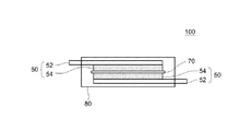
図1は、ここに開示される非水電解質二次電池10の構成を示す断面模式図である。この非水電解質二次電池10は、本質的に、正極30と負極50と非水電解液(図示せず)とを備えている。以下に各構成要素について説明する。
[Nonaqueous electrolyte secondary battery]
FIG. 1 is a schematic cross-sectional view showing a configuration of a nonaqueous electrolyte
<負極>
負極50は、負極集電体52上に負極活物質層54が備えられることで構成されている。この負極活物質層54は、負極活物質を備えている。典型的には、負極活物質がバインダ(結着剤)により互いに結合されるとともに、負極集電体52に接合された形態であり得る。そして、本発明の非水電解質二次電池10においては、負極活物質として、非晶質炭素が表面に配置された天然黒鉛(非晶質炭素被覆黒鉛)を含んでいる。このような負極50は、例えば、負極活物質とバインダとを適当な溶媒(例えば、水やN−メチル−2−ピロリドン、好ましくは水。)に分散させてなる負極ペーストを負極集電体52の表面に供給した後、乾燥して溶媒を除去することにより作製することができる。負極集電体としては、導電性の良好な金属(例えば、銅、ニッケル、チタン、ステンレス鋼等)からなる導電性部材を好適に使用することができる。
<Negative electrode>
The
なお、非晶質炭素被覆黒鉛については、粒状の黒鉛の少なくとも一部の表面に非晶質炭素が配置されているものであれば特に制限されない。好ましくは、粒状炭素の表面のほぼ全てを非晶質炭素の膜で被覆された形態である。かかる観点から、本明細書において、非晶質炭素被覆黒鉛とは、必ずしも黒鉛の外表面の全てが非晶質炭素で覆われた形態に限定されない。なお、非晶質炭素はその表面にエッジ面が多く露出しており、電荷担体の受入性が高い(すなわち、電荷担体の吸蔵・放出スピードが速い)。また、黒鉛は、理論容量が大きく、エネルギー密度に優れている。したがって、負極活物質として非晶質炭素被覆黒鉛を用いることで、大容量でエネルギー密度が高く、かつ、入出力特性に優れた非水電解質二次電池を実現することが可能となる。 The amorphous carbon-coated graphite is not particularly limited as long as amorphous carbon is disposed on at least a part of the surface of the granular graphite. Preferably, almost all of the surface of the granular carbon is covered with an amorphous carbon film. From this viewpoint, in the present specification, the amorphous carbon-coated graphite is not necessarily limited to a form in which the entire outer surface of the graphite is covered with amorphous carbon. Note that amorphous carbon has a large number of edge surfaces exposed on its surface, and has a high charge carrier acceptability (that is, the charge carrier is occluded / released quickly). Graphite has a large theoretical capacity and is excellent in energy density. Therefore, by using amorphous carbon-coated graphite as the negative electrode active material, it is possible to realize a non-aqueous electrolyte secondary battery having a large capacity, high energy density, and excellent input / output characteristics.
このような非晶質炭素被覆黒鉛は、従来公知の各種の手法によって作製することができる。例えば、先ず、原料としての黒鉛と非晶質炭素源(例えば、易黒鉛化炭素等の無機炭素材料や、有機高分子材料等)とを準備する。そして黒鉛の表面に、例えばCVD法(Chemical Vapor Deposition)等の気相法や、液相法、固相法等によって、非晶質炭素源を付着させる。黒鉛としては、塊状黒鉛、鱗片状黒鉛等の天然黒鉛、炭素前駆体を焼成処理して得られる人造黒鉛、あるいは、上記黒鉛に粉砕、篩分け、プレス等の加工処理を施したものを用いることができる。また、非晶質炭素源は、採用する非晶質炭素被覆黒鉛の作製手法にも因るため一概には言えないが、例えば、CVD法では、エチレン、アセチレン、プロピレン等の不飽和脂肪族炭化水素;メタン、エタン、プロパン等の飽和脂肪族炭化水素;ベンゼン、トルエン、ナフタレン等の芳香族炭化水素;等の各種炭化水素化合物等の、熱やプラズマ等により分解されて上記核材表面に炭素膜を形成し得る化合物(ガス)であり得る。あるいは、液相法および固相法においては、ナフタレン、アントラセン等の芳香族炭化水素、コールタールピッチ、石油ピッチ、木タールピッチ等のピッチ類等であり得る。そして、非晶質炭素源が付着された黒鉛材料を、高温(例えば500℃〜1500℃)で焼成して炭化させる。次いで、得られた炭化物を適宜粉砕、篩分けすることによって、ここに開示される性状の非晶質炭素被覆黒鉛を作製することができる。なお、非晶質炭素被覆黒鉛の性状(例えば、D50値、BET比表面積等)は、例えば使用する原料の種類や性状(特には平均粒径)、焼成・炭化温度、炭化後の粉砕や篩分け等によって調整することができる。例えば、平均粒径(D50)がおよそ5〜20μmで、BET法による比表面積がおよそ1.8〜5.6m2/g程度のものを好ましく用いることができる。上記負極活物質には、非晶質炭素被覆黒鉛以外のこの種の負極用活物質が(例えば、負極活物質の50質量%未満の割合で)含まれることを妨げない。 Such amorphous carbon-coated graphite can be produced by various conventionally known methods. For example, first, graphite and an amorphous carbon source (for example, an inorganic carbon material such as graphitizable carbon or an organic polymer material) are prepared as raw materials. Then, an amorphous carbon source is attached to the surface of the graphite by a vapor phase method such as a CVD method (Chemical Vapor Deposition), a liquid phase method, a solid phase method, or the like. As graphite, natural graphite such as massive graphite and flake graphite, artificial graphite obtained by firing a carbon precursor, or those obtained by subjecting the above graphite to processing such as pulverization, sieving, pressing, etc. Can do. In addition, the amorphous carbon source cannot be generally described because it depends on the method for producing the amorphous carbon-coated graphite employed. For example, in the CVD method, unsaturated aliphatic carbonization such as ethylene, acetylene, and propylene is used. Hydrogen: saturated aliphatic hydrocarbons such as methane, ethane, propane, etc .; aromatic hydrocarbons such as benzene, toluene, naphthalene, etc .; It can be a compound (gas) that can form a film. Alternatively, in the liquid phase method and the solid phase method, aromatic hydrocarbons such as naphthalene and anthracene, pitches such as coal tar pitch, petroleum pitch, and wood tar pitch can be used. Then, the graphite material to which the amorphous carbon source is attached is fired and carbonized at a high temperature (for example, 500 ° C. to 1500 ° C.). Next, the obtained carbide is appropriately pulverized and sieved to produce amorphous carbon-coated graphite having the properties disclosed herein. The properties of amorphous carbon-coated graphite (for example, D50 value, BET specific surface area, etc.) include, for example, the type and properties of raw materials used (particularly the average particle size), firing / carbonization temperature, pulverization and sieve after carbonization. It can be adjusted by dividing. For example, those having an average particle diameter (D50) of about 5 to 20 μm and a specific surface area by the BET method of about 1.8 to 5.6 m 2 / g can be preferably used. The negative electrode active material does not prevent this type of negative electrode active material other than amorphous carbon-coated graphite from being contained (for example, at a ratio of less than 50% by mass of the negative electrode active material).
負極活物質層54全体に占める負極活物質の割合は、およそ50質量%以上とすることが適当であり、好ましくは90質量%〜99質量%、例えば95質量%〜99質量%である。バインダを使用する場合には、負極活物質層54に占めるバインダの割合を、負極活物質100質量部に対して例えば1質量部〜10質量部とすることができ、通常はおよそ1質量部〜5質量部とすることが適当である。
そして、上記負極に適宜プレス処理を施すことによって、負極活物質層の厚みや密度を調整することができる。プレス処理後の負極活物質層の厚みは、例えば20μm以上、典型的には50μm以上であって、200μm以下、典型的には100μm以下とすることができる。また、負極活物質層の密度は特に限定されないが、例えば0.8g/cm3以上、典型的には1.0g/cm3以上であって、1.6g/cm3以下、典型的には1.5g/cm3以下、例えば1.4g/cm3以下とすることができる。
The proportion of the negative electrode active material in the entire negative electrode
Then, the thickness and density of the negative electrode active material layer can be adjusted by appropriately pressing the negative electrode. The thickness of the negative electrode active material layer after the press treatment is, for example, 20 μm or more, typically 50 μm or more, and can be 200 μm or less, typically 100 μm or less. Further, the density of the negative electrode active material layer is not particularly limited, but is, for example, 0.8 g / cm 3 or more, typically 1.0 g / cm 3 or more, and 1.6 g / cm 3 or less, typically It can be 1.5 g / cm 3 or less, for example 1.4 g / cm 3 or less.
(負極のキャパシタンス)
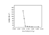
そして本発明の非水電解質二次電池においては、負極は、キャパシタンスが0.12F/g以上0.192F/g以下の範囲であることを特徴としている。負極活物質として非晶質炭素被覆黒鉛を用いて負極を作製した場合において、負極のキャパシタンスを上記範囲とすることで、例えば欠点数が少なく良好な形態の負極活物質層が備えられているとともに、負極での漏れ電流の発生が抑制された非水電解質二次電池を実現することができる。なお、欠点とは、負極活物質層の塗工ムラ、塗工スケ、塗工すじ等の形態的な不良を意味し、電極特性の低下の原因となり得る。かかる欠点は、負極活物質層の形成条件等が適切でない場合に多く発生する傾向がある。かかる形成条件とは、例えば、一例として、負極活物質層を形成するために用いる負極ペーストにおける固形分濃度(NV値)、負極活物質層(あるいは負極ペースト)中での負極活物質とバインダとの分散状態および結合状態、負極活物質の形態等であり得る。負極活物質層の形態の良否判定の基準は、例えば当該電池の用途等に応じて設定することができる。ここでは、負極のキャパシタンスが0.12F/g以上であることで、概ね全ての用途の電池について欠点が少ない(すなわち、良品である)と判断することができる。負極のキャパシタンスは、好ましくは0.13F/g以上であり、より好ましくは0.15F/g以上である。また、負極のキャパシタンスが0.192F/g以下であることで、漏れ電流が十分に抑制され得ると判断するようにしている。負極のキャパシタンスは、好ましくは0.19F/g以下であり、より好ましくは0.18F/g以下である。
(Negative capacitance)
In the nonaqueous electrolyte secondary battery of the present invention, the negative electrode has a capacitance in the range of 0.12 F / g or more and 0.192 F / g or less. When a negative electrode is produced using amorphous carbon-coated graphite as the negative electrode active material, by setting the negative electrode capacitance within the above range, for example, a negative electrode active material layer having a good shape with few defects is provided. Thus, it is possible to realize a nonaqueous electrolyte secondary battery in which generation of leakage current at the negative electrode is suppressed. In addition, a defect means morphological defects, such as coating nonuniformity of a negative electrode active material layer, coating skein, and a coating stripe, and can cause a fall of an electrode characteristic. Such defects tend to occur more often when the conditions for forming the negative electrode active material layer are not appropriate. Examples of the formation conditions include, for example, the solid content concentration (NV value) in the negative electrode paste used for forming the negative electrode active material layer, the negative electrode active material and the binder in the negative electrode active material layer (or the negative electrode paste). The dispersion state and the bonding state, the form of the negative electrode active material, and the like. The criteria for determining the quality of the form of the negative electrode active material layer can be set according to, for example, the use of the battery. Here, when the capacitance of the negative electrode is 0.12 F / g or more, it can be determined that there are few defects (that is, non-defective products) for batteries for all applications. The capacitance of the negative electrode is preferably 0.13 F / g or more, more preferably 0.15 F / g or more. Further, it is determined that the leakage current can be sufficiently suppressed when the capacitance of the negative electrode is 0.192 F / g or less. The capacitance of the negative electrode is preferably 0.19 F / g or less, more preferably 0.18 F / g or less.
なお、負極のキャパシタンスは、対象とする負極50を未充電状態で2枚用意して構成されるシンメトリーセル100について、一般的な交流インピーダンス法により測定した特定の周波数領域のインピーダンスZ(f)の定量値を、その周波数に対する電気二重層容量C(f)へと変換し、周波数0.1Hzにおける電気二重層容量の実部成分C’(f)として得た値を、負極活物質の単位質量あたりに換算することで算出することができる。より具体的には、負極のキャパシタンスは、例えば、以下の手順で求めることができる。図2は、負極のキャパシタンスを測定するために用いるシンメトリーセル100の構成を例示している。シンメトリーセル100は、対象とする負極50を下記のサイズで2枚用意し、これらをセパレータ70を介して絶縁した状態で、負極活物質層54が対向するように配置することで構成することができる。負極50は、例えば、概ね下記の範囲であれば任意の構成とすることができる。
The capacitance of the negative electrode is the impedance Z (f) of a specific frequency region measured by a general AC impedance method for the
<シンメトリーセルの基本的な構成>
負極活物質:[バインダ+増粘剤](質量比)=98:2〜99:1
目付量:3.5〜3.8mg/cm2(片面)
活物質層密度:0.95g/cm3〜1.02g/cm3
負極サイズ:4.5cm×4.7cm
電解液 :1.1mol/LのLiPF6を含むEC:DMC:EMC=3:4:3(体積比)
<Basic configuration of symmetry cell>
Negative electrode active material: [binder + thickener] (mass ratio) = 98: 2-99: 1
Weight per unit area: 3.5 to 3.8 mg / cm 2 (one side)
Active material layer density: 0.95 g / cm 3 to 1.02 g / cm 3
Negative electrode size: 4.5cm x 4.7cm
Electrolyte solution: EC containing 1.1 mol / L LiPF 6 : DMC: EMC = 3: 4: 3 (volume ratio)
負極50を構成する負極集電体52としては、上述のごとく各種の導電性の良好な金属の箔等を用いることができる。特に限定されるものではないが、好ましくは、厚みが10μm程度の銅箔である。なお、電解液の混合溶液の構成におけるECはエチレンカーボネートを、DMCはジメチルカーボネートを、EMCはエチルメチルカーボネートを示している。セパレータとしては、絶縁性とイオン透過性とを兼ね備えるものであれば特に制限されることなく、従来公知の各種のセパレータを用いることができる。上記の通り対向配置された負極50と電解液とを、例えば、外部から2枚の負極50間に電圧の印加が可能な状態として、ラミネートバック等の電池ケース80に収容することで、シンメトリーセル100を構築することができる。
As the negative electrode
このように構成したシンメトリーセル100について、交流インピーダンスを測定する。交流インピーダンスの測定方法は特に限定されず、例えば、汎用の高速フーリエ変換(FFT:Fast Fourier Transform)アナライザを用いるFFT法や、単一正弦波を掃引して測定する周波数応答アナライザ(FRA:Frequency Response Analyzer)等の各種の方式を適宜採用することができる。例えば、以下のようにして測定することができる。まず、上記の電極50間に直流電流を流し、次いで微小交流電流を重畳させたときの各周波数における応答電圧を測定することでインピーダンスを算出し、フーリエ変換することで、インピーダンスの周波数特性を求める。または、発振器から交流信号を電極50間に印加し、電圧計で試料電圧(V)を、電流計で試料電流(I)を測定する等してインピーダンスの周波数特性を求めるようにしても良い。測定に際し、典型的には、交流電圧の周波数を100000Hz程度の高周波から0.1Hz程度の低周波へと変化させる。交流電圧の振幅については特に制限されないが1〜10mV程度、例えば5mV程度を目安に設定することができる。
AC impedance is measured for the
測定により得られたインピーダンスの周波数特性は、例えば、典型的には、Cole−Coleプロット(ナイキストプロット)を作成し、等価回路にフィッティングさせて解析することで、電気二重層容量を得ることができる。本発明では、インピーダンスの周波数特性から、いわゆる電気二重層容量と呼ばれる成分を抽出し、0.1Hzという充分な低周波における電気二重層容量を「負極活物質のキャパシタンス」としている。かかる負極活物質のキャパシタンスは、具体的には、例えば以下のようにして得ることができる。まず、測定により得られた周波数fに関するインピーダンス特性は、下記式(1)で表すことができる。このインピーダンスZ(f)の関係を、電気二重層容量C(f)との関係を示す式(2)に変換する。ここで、この電気二重層容量C(f)は式(3)で表すことができ、その実部成分C’(f)と虚部成分C”(f)はそれぞれ式(4)および式(5)で表すことができる。したがって、式(4)から周波数が0.1Hzの時の電気二重層容量C’値を算出すればよい。 The frequency characteristics of the impedance obtained by the measurement can be typically obtained, for example, by creating a Cole-Cole plot (Nyquist plot) and fitting it into an equivalent circuit for analysis. . In the present invention, a so-called electric double layer capacitance component is extracted from the frequency characteristics of impedance, and the electric double layer capacitance at a sufficiently low frequency of 0.1 Hz is defined as “capacitance of the negative electrode active material”. Specifically, the capacitance of the negative electrode active material can be obtained, for example, as follows. First, the impedance characteristic regarding the frequency f obtained by the measurement can be expressed by the following formula (1). The relationship of the impedance Z (f) is converted into an equation (2) indicating the relationship with the electric double layer capacitance C (f). Here, the electric double layer capacitance C (f) can be expressed by Expression (3), and its real part component C ′ (f) and imaginary part component C ″ (f) are expressed by Expression (4) and Expression (5), respectively. Therefore, the electric double layer capacitance C ′ value when the frequency is 0.1 Hz may be calculated from the equation (4).

なお、上記で求めた0.1Hzの時の電気二重層容量C’は、シンメトリーセル100の全体に生じる総電荷量であるため、これを負極活物質の単位質量あたりの電荷量に換算することで、負極活物質のキャパシタンスとする。この計算に当たっては、下式(6)の関係から、式(7)で示される1枚の電極50の容量C1’が算出される。そして、この1枚の電極50の容量C1’を1枚の電極の活物質層に含まれる総活物質の質量で割ることで、活物質のキャパシタンス値を求めればよい。
Since the electric double layer capacity C ′ obtained at 0.1 Hz obtained above is the total amount of charge generated in the
<正極>
正極30は、典型的には、正極集電体32上に正極活物質層34が備えられることで構成されている。この正極活物質層34は、正極活物質を備えるものであれば特に限定されないが、典型的には、正極活物質が導電材と共にバインダ(結着剤)により互いに結合され、正極集電体32に接合された形態であり得る。このような正極30は、例えば、正極活物質と導電材とバインダ(結着剤)とを適当な溶媒(例えばN−メチル−2−ピロリドン)に分散させてなる正極ペーストを正極集電体32の表面に供給した後、乾燥して溶媒を除去することにより作製することができる。正極集電体32としては、導電性の良好な金属(例えばアルミニウム、ニッケル、チタン、ステンレス鋼等)からなる導電性部材を好適に使用することができる。
<Positive electrode>
The
正極活物質としては特に限定されず、非水電解質二次電池の正極活物質として使用し得る各種のものを、1種を単独で、または2種以上を混合または複合体化する等して、用いることができる。好適例として、層状系、スピネル系等のリチウム複合金属酸化物(例えば、LiNiO2、LiCoO2、LiFeO2、LiMn2O4、LiNi0.5Mn1.5O4,LiCrMnO4、LiFePO4等)が挙げられる。なかでも、構成元素としてLi,Ni,CoおよびMnを含む層状構造(典型的には、六方晶系に属する層状岩塩型構造)のリチウムニッケルコバルトマンガン複合酸化物を好ましく用いることができる。例えば、具体的には、LiNi1/3Co1/3Mn1/3O2等のいわゆる三元系のリチウム遷移金属複合酸化物は、熱安定性に優れ、且つ高いエネルギー密度を実現し得る正極活物質として好ましい。 The positive electrode active material is not particularly limited, and various types of materials that can be used as the positive electrode active material of the nonaqueous electrolyte secondary battery can be used singly or in combination of two or more. Can be used. Preferable examples include layered and spinel-based lithium composite metal oxides (for example, LiNiO 2 , LiCoO 2 , LiFeO 2 , LiMn 2 O 4 , LiNi 0.5 Mn 1.5 O 4 , LiCrMnO 4 , LiFePO 4, etc. ). Among these, lithium nickel cobalt manganese composite oxide having a layered structure (typically a layered rock salt structure belonging to a hexagonal system) containing Li, Ni, Co, and Mn as constituent elements can be preferably used. For example, specifically, so-called ternary lithium transition metal composite oxides such as LiNi 1/3 Co 1/3 Mn 1/3 O 2 are excellent in thermal stability and can realize a high energy density. Preferred as a positive electrode active material.
ここで、リチウムニッケルコバルトマンガン複合酸化物とは、Li,Ni,CoおよびMnのみを構成金属元素とする酸化物のほか、Li,Ni,CoおよびMn以外に他の少なくとも1種の金属元素(すなわち、Li,Ni,CoおよびMn以外の遷移金属元素および/または典型金属元素)を含む酸化物をも包含する意味である。かかる金属元素は、マグネシウム(Mg)、カルシウム(Ca)、ストロンチウム(Sr)、チタン(Ti)、ジルコニウム(Zr)、バナジウム(V)、ニオブ(Nb)、クロム(Cr)、モリブデン(Mo)、タングステン(W)、鉄(Fe)、ロジウム(Rh)、パラジウム(Pb)、白金(Pt)、銅(Cu)、亜鉛(Zn)、ホウ素(B)、アルミニウム(Al)、ガリウム(Ga)、インジウム(In)、スズ(Sn)、ランタン(La)、セリウム(Ce)のうちの1種または2種以上の元素であり得る。これらの金属元素の量(配合量)は特に限定されないが、通常0.01質量%〜5質量%(典型的には0.05質量%〜2質量%、例えば0.1質量%〜0.8質量%)であり得る。 Here, the lithium nickel cobalt manganese composite oxide is an oxide containing only Li, Ni, Co and Mn as constituent metal elements, and at least one other metal element in addition to Li, Ni, Co and Mn ( That is, it is meant to include oxides containing transition metal elements and / or typical metal elements other than Li, Ni, Co and Mn. Such metal elements include magnesium (Mg), calcium (Ca), strontium (Sr), titanium (Ti), zirconium (Zr), vanadium (V), niobium (Nb), chromium (Cr), molybdenum (Mo), Tungsten (W), iron (Fe), rhodium (Rh), palladium (Pb), platinum (Pt), copper (Cu), zinc (Zn), boron (B), aluminum (Al), gallium (Ga), It may be one or more elements of indium (In), tin (Sn), lanthanum (La), and cerium (Ce). The amount (mixing amount) of these metal elements is not particularly limited, but is usually 0.01% by mass to 5% by mass (typically 0.05% by mass to 2% by mass, for example, 0.1% by mass to 0.00%). 8% by weight).
導電材としては、例えば、カーボンブラック(典型的にはアセチレンブラック、ケッチェンブラック)、活性炭、黒鉛、炭素繊維等の炭素材料を好適に用いることができる。バインダとしては、例えば、ポリフッ化ビニリデン(PVdF)等のハロゲン化ビニル樹脂、ポリエチレンオキサイド(PEO)等のポリアルキレンオキサイドに代表されるポリマー材料を好適に用いることができる。 As the conductive material, for example, carbon materials such as carbon black (typically acetylene black and ketjen black), activated carbon, graphite, and carbon fiber can be suitably used. As the binder, for example, a vinyl halide resin such as polyvinylidene fluoride (PVdF) or a polymer material typified by polyalkylene oxide such as polyethylene oxide (PEO) can be preferably used.
正極活物質層34全体に占める正極活物質の割合は、およそ50質量%以上、典型的には50質量%以上95質量%以下とすることが適当であり、通常はおよそ70質量%以上95質量%以下であることが好ましい。正極活物質層34に占める導電材の割合は、正極活物質100質量部に対して、例えばおよそ0.1質量部〜20質量部とすることができ、通常はおよそ1質量部〜15質量部、例えば2質量部〜10質量部、典型的には3質量部〜7質量部とすることが好ましい。正極活物質層に占めるバインダの割合は、正極活物質100質量部に対して、例えばおよそ0.5質量部〜10質量部とすることができ、通常はおよそ1質量部〜8質量部、例えば2質量部〜7質量部、典型的には2質量部〜5質量部とすることが好ましい。
また、正極活物質層34の厚みは、例えば20μm以上、典型的には50μm以上であって、200μm以下、典型的には100μm以下とすることができる。また、正極活物質層34の密度は特に限定されないが、例えば1.5g/cm3以上、典型的には2g/cm3以上であって、4.5g/cm3以下、典型的には4.2g/cm3以下とすることができる。上記範囲を満たす正極活物質層は、高い電池性能(例えば、高いエネルギー密度や出力密度)を実現し得る。
The proportion of the positive electrode active material in the entire positive electrode
The thickness of the positive electrode
<正極と負極との容量比>
上記の正極30と負極50とは、電荷担体の受入特性の違い等から、容量比が調整されていることが好ましい。具体的には、正極容量Cc(mAh)と負極容量Ca(mAh)との比(Ca/Cc)を、1.0〜2.0とすることが適当であり、1.5〜1.9(例えば1.7〜1.9)とすることが好ましい。ここで、正極容量Cc(mAh)は、正極活物質の単位質量当たりの理論容量(mAh/g)と該正極活物質の質量(g)との積として規定される。また、負極容量Ca(mAh)は、負極活物質の単位質量当たりの理論容量(mAh/g)と該負極活物質の質量(g)との積として規定される。上記の通り、対向する正負極の容量比を調整することで、電池容量やエネルギー密度等の電池特性を良好に維持しつつ、正負極間の電荷バランスを整えることができる。延いては、負極表面に電荷担体が析出することを好適に抑制することができる。
<Capacitance ratio between positive electrode and negative electrode>
It is preferable that the capacity ratio of the
<HRL>
本発明においては、上記の正極30と負極50との間に、図示しないHRLを本質的に含むようにしている。かかるHRLは、耐熱性を有する多孔質の絶縁層である。HRLは、電池が発熱した際に電池の電気化学反応を停止させるシャットダウン温度(典型的には、80℃〜140℃)に対する耐熱性を有し、かつ、電荷担体の透過性を確保し得る多孔質構造を備えるものであれば、その構造や材質等に特に制限はない。例えば、150℃以上、典型的には200℃以上の温度で軟化や溶融をせず、多孔質構造を維持し得る程度の耐熱性を備える材料から構成することができる。具体的には、上記の耐熱性および絶縁性を備える樹脂材料、無機材料、ガラス材料、およびこれらの複合材料などにより構成することができる。かかるHRLの好適な例としては、典型的には、無機フィラーとバインダとから構成される層である。無機フィラーとしては、典型的には、粒状または繊維状の、アルミナ(Al2O3)、マグネシア(MgO)、シリカ(SiO2)、チタニア(TiO2)等の無機酸化物、窒化アルミニウム、窒化ケイ素等の窒化物、水酸化カルシウム、水酸化マグネシウム、水酸化アルミニウム等の金属水酸化物、マイカ、タルク、ベーマイト、ゼオライト、アパタイト、カオリン等の粘土鉱物、ガラス繊維等が挙げられる。このような無機フィラーとしては、品質が安定しているうえに安価で入手が容易なアルミナ(Al2O3)、ベーマイト(Al2O3・H2O)等を用いるのがより好ましい。かかる無機フィラーの平均粒径(D50)は、例えば、およそ0.1μm〜5.0μm程度とすることができ、より限定的には0.2μm〜2.0μm程度とするのが好ましい。かかる無機フィラーの比表面積としては、BET法に基づく比表面積が、2.8m2/g〜100m2/g程度のものをおおよその目安として用いることができる。
また、バインダとしては、例えば上記正極や負極を構成するのに用いる各種ポリマー材料とすることができる。
HRLが無機フィラーを含む場合、HRLの全体に占める無機フィラーの割合は、およそ50質量%以上とすることが適当であり、通常は85質量%〜99.8質量%(例えば90質量%〜99質量%)とすることが好ましい。バインダを使用する場合には、HRLの全体に占めるバインダの割合は、例えばおよそ1質量%〜10質量%とすることができ、通常はおよそ1質量%〜5質量%とすることが好ましい。
<HRL>
In the present invention, HRL (not shown) is essentially included between the
Moreover, as a binder, it can be set as the various polymer materials used, for example to comprise the said positive electrode and negative electrode.
When the HRL contains an inorganic filler, the proportion of the inorganic filler in the entire HRL is suitably about 50% by mass or more, and usually 85% by mass to 99.8% by mass (for example, 90% by mass to 99%). Mass%) is preferred. When using a binder, the ratio of the binder to the whole HRL can be, for example, approximately 1% by mass to 10% by mass, and is preferably approximately 1% by mass to 5% by mass.
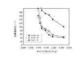
なお、ここに開示される発明において、HRLの平均厚みは、2μm以上10μm以下とするのが肝要である。HRLの平均厚みは、より好ましくは3μm以上であり、さらに好ましくは4μm以上である。ここに開示される非水電解質二次電池が負極活物質として用いる非晶質炭素被覆黒鉛は反応性が高く、例えば、負極の漏れ電流を増大させる原因となり得る。HRLの平均厚みが2μm以上であることで、充放電を繰り返しても微短絡が生じ難く、また漏れ電流の発生量を低く抑えることができる。これにより、例えば、電池が発熱してシャットダウンした後に、電池の電気化学反応を迅速に停止させて更なる発熱を抑制することができる。また、HRLの平均厚みは、好ましくは9μm以下であり、さらに好ましくは8μm以下である。かかる構成とすることで、内部抵抗を低く抑えることができ、高出入力特性を長期に亘って実現することができる。 In the invention disclosed herein, it is important that the average thickness of the HRL is 2 μm or more and 10 μm or less. The average thickness of HRL is more preferably 3 μm or more, and further preferably 4 μm or more. The amorphous carbon-coated graphite used as the negative electrode active material for the nonaqueous electrolyte secondary battery disclosed herein has high reactivity, and can cause, for example, an increase in the leakage current of the negative electrode. When the average thickness of the HRL is 2 μm or more, it is difficult for a fine short circuit to occur even when charging and discharging are repeated, and the amount of leakage current generated can be kept low. Thereby, for example, after the battery generates heat and shuts down, the electrochemical reaction of the battery can be quickly stopped to suppress further heat generation. The average thickness of the HRL is preferably 9 μm or less, more preferably 8 μm or less. With this configuration, the internal resistance can be kept low, and high input / output characteristics can be realized over a long period of time.
<セパレータ>
セパレータ70は、正極活物質層34と負極活物質層54とを絶縁するとともに、電荷担体の透過性を有する構成材料であり、典型的には上記正極30と負極50との間に配置される。セパレータ70は、非水電解質の保持機能やシャットダウン機能を備えるようにしてもよい。かかるセパレータとしては、ポリエチレン(PE)、ポリプロピレン(PP)、ポリエステル、セルロース、ポリアミド等の樹脂からなる微多孔質樹脂シートを好適に用いることができる。なかでも、PEやPP等のポリオレフィン樹脂からなる微多孔質シートは、シャットダウン温度を80℃〜140℃(典型的には110℃〜140℃、例えば120℃〜135℃)の範囲で好適に設定できるために好ましい。かかるセパレータは、単一の材料から構成される単層構造であってもよく、材質や性状(例えば、平均厚みや空孔率等)の異なる2種以上の微多孔質樹脂シートが積層された構造(例えば、PE層の両面にPP層が積層された三層構造)であってもよい。
なお、本発明の好ましい態様においては、上記HRLをセパレータ70の少なくとも一方の表面(例えば、片側または両面)に配設した形態とすることができる。このようなセパレータ70は、例えば、上記のHRL層を構成する材料(典型的には、無機フィラーと必要に応じて用いられるバインダ等)を適当な溶媒(例えば水)に分散させてなるペースト状またはスラリー状の組成物を、セパレータ70の表面に供給した後、乾燥させて溶媒を除去することにより作製することができる。
<Separator>
The
In a preferred embodiment of the present invention, the HRL may be disposed on at least one surface (for example, one side or both sides) of the
セパレータ70の平均厚み(HRL付きセパレータについては、HRLを除いた厚み)は特に限定されないが、通常、10μm以上、典型的には15μm以上、例えば17μm以上とすることができる。また、上限については、40μm以下、典型的には30μm以下、例えば25μm以下とすることができる。基材の平均厚みが上記範囲内にあることで、電荷担体の透過性を良好に保つことができ、かつ、微小な短絡(漏れ電流)がより生じ難くなる。このため、入出力密度と安全性とを高いレベルで両立することができる。 The average thickness of the separator 70 (thickness excluding HRL for the separator with HRL) is not particularly limited, but is usually 10 μm or more, typically 15 μm or more, for example, 17 μm or more. The upper limit may be 40 μm or less, typically 30 μm or less, for example, 25 μm or less. When the average thickness of the substrate is within the above range, the charge carrier permeability can be kept good, and a minute short circuit (leakage current) is less likely to occur. For this reason, input / output density and safety can be achieved at a high level.
ここに開示される発明において、上記のHRLは、負極50に接するように配置されていることが好ましい。例えば、負極50の表面にHRLが形成されていても良い。また、例えば、HRLがセパレータ70の片面または両面に配設されている場合には、かかるHRLが負極50に接するようにHRL付きセパレータ70が配置されていることが好ましい。ここに開示される非水電解質二次電池10は、負極活物質として非晶質炭素被覆黒鉛を用いているため、その局所的な反応性の高さから、充放電の繰り返しや過充電等により負極の表面に電荷担体が析出しやすい傾向にある。かかる構成によると、例えば負極の表面にリチウムデンドライト等が析出し得る状況にあっても、内部短絡を効果的に抑制することができる。したがって、漏れ電流を小さくすることができ、安全性や信頼性に優れた電池10を実現することができる。
In the invention disclosed herein, the HRL is preferably arranged so as to be in contact with the
<非水電解質>
非水電解質としては、典型的には、非水溶媒中に支持塩(例えば、リチウム塩、ナトリウム塩、マグネシウム塩等であり、リチウムイオン二次電池ではリチウム塩)を溶解または分散させたものを採用し得る。あるいは、液状の非水電解質にポリマーが添加されてゲル状となった、いわゆる固体電解質であってもよい。
非水溶媒としては、一般的な非水電解質二次電池において電解液として用いられるカーボネート類、エーテル類、エステル類、ニトリル類、スルホン類、ラクトン類等の各種の有機溶媒を特に制限なく用いることができる。例えば、具体的には、エチレンカーボネート(EC)、プロピレンカーボネート(PC)、ジエチルカーボネート(DEC)、ジメチルカーボネート(DMC)、エチルメチルカーボネート(EMC)等が挙げられる。このような非水溶媒は、1種を単独で、あるいは2種以上を混合溶媒として用いることができる。
支持塩としては、一般的な非水電解質二次電池に用いられる各種のものを適宜選択して採用することができる。例えば、LiPF6、LiBF4、LiClO4、LiAsF6、Li(CF3SO2)2N、LiCF3SO3等のリチウム塩を用いることが例示される。このような支持塩は、1種を単独で、あるいは2種以上を組み合わせて用いてもよい。かかる支持塩は、非水電解質における濃度が0.7mol/L〜1.3mol/Lの範囲内となるように調製することが好ましい。
<Nonaqueous electrolyte>
As the non-aqueous electrolyte, typically, a non-aqueous solvent in which a supporting salt (for example, a lithium salt, a sodium salt, a magnesium salt, etc., or a lithium salt in a lithium ion secondary battery) is dissolved or dispersed is used. Can be adopted. Alternatively, a so-called solid electrolyte in which a polymer is added to a liquid non-aqueous electrolyte to form a gel may be used.
As the non-aqueous solvent, various organic solvents such as carbonates, ethers, esters, nitriles, sulfones, and lactones that are used as electrolytes in general non-aqueous electrolyte secondary batteries should be used without particular limitation. Can do. Specific examples include ethylene carbonate (EC), propylene carbonate (PC), diethyl carbonate (DEC), dimethyl carbonate (DMC), and ethyl methyl carbonate (EMC). Such a non-aqueous solvent can be used alone or in combination of two or more.
As the supporting salt, various kinds of salts used for general nonaqueous electrolyte secondary batteries can be appropriately selected and employed. For example, the use of lithium salts such as LiPF 6 , LiBF 4 , LiClO 4 , LiAsF 6 , Li (CF 3 SO 2 ) 2 N, LiCF 3 SO 3 is exemplified. Such supporting salts may be used singly or in combination of two or more. Such a supporting salt is preferably prepared so that the concentration in the non-aqueous electrolyte is within the range of 0.7 mol / L to 1.3 mol / L.
また、非水電解質は、本発明の非水電解質二次電池の特性を損なわない限り、各種の添加剤等を含んでいても良い。かかる添加剤としては、ガス発生剤、皮膜形成剤等として、電池の入出力特性の向上、サイクル特性の向上、初期充放電効率の向上等のうち、1または2以上の目的で使用され得る。かかる添加剤としては、具体的には、フルオロリン酸塩(好ましくはジフルオロリン酸塩。例えば、LiPO2F2で表されるジフルオロリン酸リチウム)、リチウムビス(オキサラト)ボレート(LiBOB)等のオキサラト錯体化合物が挙げられる。非水電解質全体に対するこれらの添加剤の濃度は、通常0.1mol/L以下(典型的には0.005mol/L〜0.1mol/L)とすることが適当である。 In addition, the nonaqueous electrolyte may contain various additives and the like as long as the characteristics of the nonaqueous electrolyte secondary battery of the present invention are not impaired. As such an additive, a gas generating agent, a film forming agent, etc. can be used for one or more purposes among improvement of input / output characteristics of a battery, improvement of cycle characteristics, improvement of initial charge / discharge efficiency and the like. Specific examples of such additives include fluorophosphate (preferably difluorophosphate. For example, lithium difluorophosphate represented by LiPO 2 F 2 ), lithium bis (oxalato) borate (LiBOB), and the like. An oxalato complex compound is mentioned. The concentration of these additives relative to the entire nonaqueous electrolyte is usually 0.1 mol / L or less (typically 0.005 mol / L to 0.1 mol / L).
以下、特に限定することを意図したものではないが、本発明の一実施形態に係る非水電解質二次電池10の構成について、図1に示す典型的な角型電池の例を適宜参照しつつ、さらに詳細に説明する。図1に示す非水電解質二次電池10は、正極30と負極50とを備える電極体20が、図示しない非水電解質とともに扁平な箱型形状の電池ケース80に収容された構成を有している。電池ケース80は、扁平な直方体の一の面(図では上面)が開放された形状のケース本体84と、その開口面を塞ぐ蓋体82とを備えている。電池ケース80の上面(典型的には、蓋体82)には、外部接続用の正極端子40と、外部接続用の負極端子60とが、電池ケース80とは絶縁された状態で配設されている。また、電池ケース80の上面(典型的には、蓋体82)には、従来の非水電解質二次電池の電池ケースと同様に、電池ケース80の内部で発生したガスを外部に排出するための安全弁88や、電解液の注入を行う注液口86が備えられている。かかる構成の非水電解質二次電池10は、例えば、蓋体82に電極体20を取り付けた後、ケース本体84の開口面から電極体20をその内部に収容しつつ、ケース本体84の開口面を蓋体82で封止することで電池10を組み立てる。次いで、蓋体82に設けられた注液口86から非水電解質を注入し、かかる注液口86を溶接等により封止することによって構築することができる。
Hereinafter, although not intended to be particularly limited, the configuration of the nonaqueous electrolyte
なお、電極体20は、具体的には、正極30と負極50とが、例えば、HRL付きのセパレータを介して重ね合わされて構成されている。図1に示される電極体20は、長尺シート状の正極(正極シート)30と、長尺シート状の負極(負極シート)50とが、2枚のセパレータ70を介して互いに絶縁されるよう重ね合わされ、捲回された捲回電極体20である。かかる捲回電極体20は、電池ケース80に対応した扁平形状に捲回されているか、あるいは、成形されている。正極30は、長尺状の正極集電体32の少なくとも一方の表面(典型的には両面)に、長手方向の端部に沿って正極集電体32が露出するように正極活物質層34が形成されている。負極50は、長尺状の負極集電体52の少なくとも一方の表面(典型的には両面)に、長手方向の端部に沿って負極集電体52が露出するように負極活物質層54が形成されている。かかる形態の正極30および負極50を、互いの集電体32,52の露出部が反対の端部に突出するように重ね合わせて捲回することで、捲回電極体20においても捲回軸方向の両端部に当該露出部が突出されている。そして、かかる正極集電体32および負極集電体52が、それぞれ、正極端子40および負極端子60に電気的に接続されている。これにより、電極体20に蓄積されている電荷をこれら端子40,60を介して外部に出力(放電)したり、これら端子40,60を介して外部から電極体20に電荷を入力(充電)したりすることができる。
Specifically, the
ここに開示される非水電解質二次電池は各種用途に利用可能であるが、例えば、従来品に比べて優れた入出力特性と高い安全性とを兼ね備えたものであり得る。また、これらの優れた電池性能と信頼性(過充電時の熱安定性等の安全性を包含する)とを高いレベルで両立可能なものであり得る。したがって、このような特徴を活かして、高エネルギー密度や高入出力密度が要求される用途、高い信頼性を要求される用途で好ましく用いることができる。かかる用途としては、例えば、プラグインハイブリッド自動車、ハイブリッド自動車、電気自動車等の車両に搭載される駆動用電源が挙げられる。なお、かかる二次電池は、典型的には複数個を直列および/または並列に接続してなる組電池の形態で使用され得る。
以下、具体的な実施例として、ここに開示される非水電解質二次電池を作製した。なお、本発明をかかる具体例に示すものに限定することを意図したものではない。
The non-aqueous electrolyte secondary battery disclosed herein can be used for various applications. For example, the non-aqueous electrolyte secondary battery can have both excellent input / output characteristics and high safety compared to conventional products. In addition, these excellent battery performance and reliability (including safety such as thermal stability during overcharge) can be compatible at a high level. Therefore, taking advantage of such characteristics, it can be preferably used in applications requiring high energy density and high input / output density and applications requiring high reliability. Examples of such applications include drive power supplies mounted on vehicles such as plug-in hybrid vehicles, hybrid vehicles, and electric vehicles. Such secondary batteries can typically be used in the form of an assembled battery in which a plurality are connected in series and / or in parallel.
Hereinafter, the nonaqueous electrolyte secondary battery disclosed here was produced as a specific example. It should be noted that the present invention is not intended to be limited to those shown in the specific examples.
[負極の作製]
天然黒鉛96質量%に対して、非晶質炭素源としてのピッチを4質量%の割合で配合し、混合することでピッチを天然黒鉛に含浸させた。このピッチ付き天然黒鉛を、不活性雰囲気下、800℃〜1300℃で10時間焼成し、表面に非晶質炭素が配置された黒鉛(非晶質炭素被覆黒鉛)からなる負極活物質を得た。得られた負極活物質は、篩いにかけ、平均粒径(D50)が5μm〜20μmであって、BET比表面積が1.8〜5.6m2/gの範囲となるように調整した。
この天然黒鉛(C)と、バインダとしてのスチレンブタジエンゴム(SBR)と、分散剤としてのカルボキシメチルセルロース(CMC)とを、これら材料の質量比が、C:SBR:CMC=98.6:0.7:0.7となるようイオン交換水を加えて混練することで、負極ペーストを調製した。なお、ここで、ペーストを混練する際の水分量を調整することでペースト粘度が1000mPa・s〜2000mPa・s(25℃、1rpm)の範囲で7通りの固練り時の固形分濃度(以下、固練りNV値という。)の負極ペースト(a)〜(g)を用意した。
[Preparation of negative electrode]
The pitch as an amorphous carbon source was blended at a ratio of 4% by mass with respect to 96% by mass of natural graphite, and the pitch was impregnated into natural graphite by mixing. This natural graphite with pitch was fired at 800 ° C. to 1300 ° C. for 10 hours in an inert atmosphere to obtain a negative electrode active material made of graphite (amorphous carbon-coated graphite) having amorphous carbon disposed on the surface. . The obtained negative electrode active material was sieved and adjusted so that the average particle size (D50) was 5 μm to 20 μm and the BET specific surface area was in the range of 1.8 to 5.6 m 2 / g.
Mass ratio of these natural graphite (C), styrene butadiene rubber (SBR) as a binder, and carboxymethyl cellulose (CMC) as a dispersant is C: SBR: CMC = 98.6: 0. 7: A negative electrode paste was prepared by adding ion-exchanged water so as to be 0.7 and kneading. Here, by adjusting the amount of water when kneading the paste, the solid content concentration during the seven kneading (hereinafter referred to as “paste viscosity” in the range of 1000 mPa · s to 2000 mPa · s (25 ° C., 1 rpm)) Negative pastes (a) to (g) having a kneaded NV value) were prepared.
[塗工安定性の評価]
ここでは、上記の負極ペースト(a)〜(g)を用いて負極集電体にストライプ塗工し、圧延プレスすることによって負極シート(a)〜(g)を用意した。具体的には、各負極ペーストを、負極集電体としての厚さ10μmの銅箔に、片面の塗布量が3.5mg/cm2〜3.8mg/cm2となるように塗付し、乾燥させた後、負極活物質層密度が0.95g/cm3〜1.02g/cm3となるように圧延プレスすることによって、負極集電体上に負極活物質層を有する負極シートを得た。
そして、このようにして作製した負極のキャパシタンスと、負極ペーストの固練りNV値、および、塗工安定性との関係を調べた。
<欠点数の計測>
このようにして用意した負極(a)〜(g)の各々について、塗工スケの欠点数を調べることで、各電極の塗工安定性を調べた。欠点数(塗工スケ)の計測には画像検査装置を用いた。集電体に負極ペーストを塗工した後、塗工ムラが生じて集電体がφ1mmの領域で透けている状態を「塗工スケ」とし、その塗工スケの発生数を計測した。その結果を下記の表1に示した。
[Evaluation of coating stability]
Here, stripe coating was carried out to the negative electrode collector using said negative electrode paste (a)-(g), and the negative electrode sheets (a)-(g) were prepared by carrying out rolling press. Specifically, each negative electrode paste, a copper foil having a thickness of 10μm as a negative electrode collector, subjected coated as single side coating amount is 3.5mg / cm 2 ~3.8mg / cm 2 , the resulting dried, by negative electrode active material layer density is rolled pressed to the 0.95g / cm 3 ~1.02g / cm 3 , a negative electrode sheet having a negative electrode active material layer on an anode current collector It was.
Then, the relationship between the capacitance of the negative electrode thus prepared, the NV value of the negative electrode paste, and the coating stability was examined.
<Measurement of number of defects>
With respect to each of the negative electrodes (a) to (g) thus prepared, the coating stability of each electrode was examined by examining the number of defects of the coating scale. An image inspection apparatus was used to measure the number of defects (coating scale). After the negative electrode paste was applied to the current collector, the state in which coating unevenness occurred and the current collector was transparent in the region of φ1 mm was defined as “coating scale”, and the number of occurrences of the coating scale was measured. The results are shown in Table 1 below.
<キャパシタンスの測定>
また、用意した負極(a)〜(g)のキャパシタンスを、交流インピーダンス法を用いて測定した。具体的には、先ず、負極シート(a)〜(g)から4.5cm×4.7cm(負極活物質層の面積:約21.15cm2)の大きさに負極をそれぞれ2枚ずつ切り出し、真空中、80℃、12時間の条件で乾燥させた。この2枚の負極を、ポリプロピレンからなる微多孔質膜(HRL無し)からなるセパレータを介して負極活物質層が対向するように重ねあわせ、1mlの非水電解液を真空含浸させるとともにラミネートバッグに収容して、シンメトリーセル(a)〜(g)を構築した。非水電解液としては、エチレンカーボネート(EC)とジメチルカーボネート(DMC)とエチルメチルカーボネート(EMC)とをEC:DMC:EMC=3:4:3の体積比で含む混合溶媒に、1.1mol/LのLiPF6を溶解させたものを用いた。
<Measurement of capacitance>
Moreover, the capacitance of the prepared negative electrodes (a) to (g) was measured using an AC impedance method. Specifically, first, two negative electrodes were cut out from the negative electrode sheets (a) to (g) to a size of 4.5 cm × 4.7 cm (negative electrode active material layer area: about 21.15 cm 2 ), The film was dried in vacuum at 80 ° C. for 12 hours. The two negative electrodes are overlapped with a separator made of a microporous membrane (without HRL) made of polypropylene so that the negative electrode active material layers face each other, and 1 ml of nonaqueous electrolyte is vacuum impregnated and laminated bag Housed and constructed symmetry cells (a)-(g). As a non-aqueous electrolyte, 1.1 mol in a mixed solvent containing ethylene carbonate (EC), dimethyl carbonate (DMC), and ethyl methyl carbonate (EMC) at a volume ratio of EC: DMC: EMC = 3: 4: 3. / L LiPF 6 dissolved was used.
上記のシンメトリーセル(a)〜(g)について、交流インピーダンスの測定を行い、それぞれの負極のキャパシタンスを算出した。交流インピーダンスの測定は、ソーラトロン社製「1287型ポテンショ/ガルバノスタット」および「1255B型周波数応答アナライザ(FRA)」を用い、25℃で入力電圧を5mVとし、10000Hz〜0.1Hzの範囲で周波数依存性のインピーダンスを測定した。キャパシタンスの解析には、ソーラトロン社製の解析ソフトウェア「ZPlot/CorrWare」を用い、インピーダンス測定結果を周波数に対する電気二重層容量成分の関係に変換し、この周波数と電気二重層容量成分との関係から、0.1Hzにおける電気二重層容量を負極活物質の単位質量(g)当たりの値に変換することで、負極のキャパシタンスとした。これにより得られた負極(a)〜(g)のキャパシタンスを、下記の表1に示した。また、キャパシタンスと、NV値および欠点数との関係を、図3および図4にそれぞれ示した。 About said symmetry cell (a)-(g), the alternating current impedance was measured and the capacitance of each negative electrode was computed. AC impedance is measured using Solartron's “1287 type potentio / galvanostat” and “1255B type frequency response analyzer (FRA)”. The input voltage is 5 mV at 25 ° C. and the frequency depends on the frequency range from 10,000 Hz to 0.1 Hz. Sex impedance was measured. In the analysis of the capacitance, using the analysis software “ZPlot / Corware” manufactured by Solartron, the impedance measurement result is converted into the relationship of the electric double layer capacitance component to the frequency, and from the relationship between this frequency and the electric double layer capacitance component, The capacitance of the negative electrode was obtained by converting the electric double layer capacity at 0.1 Hz to a value per unit mass (g) of the negative electrode active material. The capacitances of the negative electrodes (a) to (g) thus obtained are shown in Table 1 below. The relationship between the capacitance, the NV value, and the number of defects is shown in FIGS. 3 and 4, respectively.
表1および図3〜4から明らかなように、同一の材料を使用し、同一形態(負極活物質層の配合、塗布量、密度等)の負極を形成したにも関わらず、負極ペーストの調製時の固練りNV値の変化を負極のキャパシタンスが良く反映していることが解る。そして、キャパシタンスが0.12F/gよりも低下すると急激に、負極活物質層の欠点数が増えることが解かる。これは、負極ペーストのNV値が上昇することで負極ペースト中の水分量が不足し、CMCの溶解および分散が十分に行われなかったことから、結果として負極ペーストの塗工性が安定せず、負極活物質層に欠陥が発生したものと考えられる。このことから、負極のキャパシタンスにより負極形成時の状態(塗工安定性)をも評価することができ、負極のキャパシタンスは0.12F/g以上であることが適切であると確認できた。 As is clear from Table 1 and FIGS. 3 to 4, the preparation of the negative electrode paste was performed despite using the same material and forming the negative electrode in the same form (formulation of negative electrode active material layer, coating amount, density, etc.). It can be seen that the capacitance of the negative electrode reflects the change in the kneading NV value over time. And when capacitance falls below 0.12 F / g, it turns out that the number of faults of a negative electrode active material layer increases rapidly. This is because as the NV value of the negative electrode paste increases, the amount of water in the negative electrode paste is insufficient, and CMC is not sufficiently dissolved and dispersed. As a result, the coatability of the negative electrode paste is not stable. It is considered that a defect occurred in the negative electrode active material layer. From this, the state at the time of negative electrode formation (coating stability) can also be evaluated by the capacitance of the negative electrode, and it has been confirmed that the capacitance of the negative electrode is suitably 0.12 F / g or more.
(サンプルNo.1〜28)
[評価用リチウムイオン電池の構築]
<負極>
上記で用意した負極ペースト(a)〜(g)を用い、上記と同様の厚さ10μmの銅箔に、両面での目付量が7.3mg/cm2となるように負極ペーストを塗付し、乾燥させた後、負極活物質層密度が0.9g/cm3〜1.3g/cm3となるように圧延プレスすることによって、負極集電体上に負極活物質層を有する負極シートを用意した。この負極シートを所定の大きさにスリットし、負極活物質層の幅が102mmで長さが3200mmの負極を切り出し、負極1〜7とした。
(Sample Nos. 1-28)
[Construction of evaluation lithium-ion battery]
<Negative electrode>
Using the negative electrode pastes (a) to (g) prepared above, apply the negative electrode paste to a copper foil having a thickness of 10 μm similar to the above so that the weight per unit area is 7.3 mg / cm 2. after drying, by negative electrode active material layer density is rolled pressed so as to 0.9g / cm 3 ~1.3g / cm 3 , a negative electrode sheet having a negative electrode active material layer on an anode current collector Prepared. This negative electrode sheet was slit to a predetermined size, and a negative electrode having a negative electrode active material layer width of 102 mm and a length of 3200 mm was cut out to form negative electrodes 1 to 7.
<正極>
正極活物質として、Li1.14Ni0.34Co0.33Mn0.33O2を用意した。具体的には、原料化合物としての硫酸ニッケル(NiSO4)と硫酸コバルト(CoSO4)と硫酸マンガン(MnSO4)とを、Ni:Co:Mnのモル比がおよそ1:1:1となるよう秤量し、水に溶解させることで、Niイオン,Coイオン,Mnイオンを含む混合溶液を用意した。この混合液を25質量%の水酸化ナトリウム水溶液で中和して、Ni0.34Co0.33Mn0.33(OH)2を基本構成とする複合水酸化物(前駆体水酸化物)を得た。そして、この前駆体水酸化物とリチウム源としての炭酸リチウム(Li2CO3)とを、(Ni+Co+Mn):Liのモル比が1.14:1となるように混合し、大気雰囲気中、800℃〜950℃で5時間〜15時間焼成した。その後、かかる焼成物を冷却し、解砕し、篩い分けを行った。これにより、Li1.14Ni0.34Co0.33Mn0.33O2で表される平均組成の正極活物質(LNCM)を得た。得られた正極活物質の性状を調べたところ、平均粒径D50が3〜8μmであり、BET比表面積が0.5m2/g〜1.9m2/gであった。なお、一般的な誘導結合プラズマ質量分析計を用いてかかる正極活物質の構成元素の分析を行ったところ、Li,Ni,Co,Mnに加えて、微量の遷移金属元素、アルカリ金属元素およびアルカリ土類金属元素が検出された。
<Positive electrode>
Li 1.14 Ni 0.34 Co 0.33 Mn 0.33 O 2 was prepared as a positive electrode active material. Specifically, nickel sulfate (NiSO 4 ), cobalt sulfate (CoSO 4 ), and manganese sulfate (MnSO 4 ) as raw material compounds have a molar ratio of Ni: Co: Mn of approximately 1: 1: 1. A mixed solution containing Ni ions, Co ions, and Mn ions was prepared by weighing and dissolving in water. This mixed solution is neutralized with a 25% by mass aqueous sodium hydroxide solution to form a composite hydroxide (precursor hydroxide) having Ni 0.34 Co 0.33 Mn 0.33 (OH) 2 as a basic component. Got. Then, this precursor hydroxide and lithium carbonate (Li 2 CO 3 ) as a lithium source are mixed so that the molar ratio of (Ni + Co + Mn): Li is 1.14: 1. Calcination was performed at 950 to 950 ° C. for 5 to 15 hours. Thereafter, the fired product was cooled, crushed and sieved. This gave a positive electrode active material having an average composition represented by Li 1.14 Ni 0.34 Co 0.33 Mn 0.33 O 2 (LNCM). Examination of the properties of the obtained positive electrode active material, the average particle diameter D50 is 3 to 8 [mu] m, BET specific surface area of 0.5m 2 /g~1.9m 2 / g. The constituent elements of the positive electrode active material were analyzed using a general inductively coupled plasma mass spectrometer. In addition to Li, Ni, Co, and Mn, trace amounts of transition metal elements, alkali metal elements, and alkalis were analyzed. An earth metal element was detected.
上記で用意した正極活物質(LNCM)と、導電材としてのアセチレンブラック(AB)と、バインダとしてのポリフッ化ビニリデン(PVdF)とを、これら材料の質量比が90:8:2となるようにN−メチルピロリドン(NMP)と混合して、正極ペーストを調製した。この正極ペーストを、正極集電体としての厚さ15μmの長尺状アルミニウム箔に、両面を合計した目付量が11.2mg/cm2となるよう塗付し、乾燥した後、正極活物質層の密度が1.8g/cm3〜2.4g/cm3となるように圧延プレスすることにより、正極集電体上に正極活物質層を有する正極シートを用意した。そしてこのシートを、正極活物質層の幅が98mm、長さが3000mmとなるように切り出して、正極とした。 The positive electrode active material (LNCM) prepared above, acetylene black (AB) as a conductive material, and polyvinylidene fluoride (PVdF) as a binder so that the mass ratio of these materials is 90: 8: 2. A positive electrode paste was prepared by mixing with N-methylpyrrolidone (NMP). This positive electrode paste was applied to a long aluminum foil having a thickness of 15 μm as a positive electrode current collector so that the total weight of both surfaces was 11.2 mg / cm 2 and dried, and then a positive electrode active material layer density of by rolling press so that the 1.8g / cm 3 ~2.4g / cm 3 , was prepared positive electrode sheet having a positive electrode active material layer on the positive electrode current collector. And this sheet | seat was cut out so that the width | variety of a positive electrode active material layer might be 98 mm and length might be 3000 mm, and it was set as the positive electrode.
<リチウムイオン電池の構築>
上記で用意した負極1〜7と正極とをセパレータを介してセパレータを間に介して重ね合わせた。セパレータとしては、平均厚みが20μmのポリエチレンからなる微多孔質膜を基材とし、かかる基材の片面にアルミナ微粒子を含むHRLを備えたものを用い、このHRLが負極活物質に対向するように重ねて配置した。なお、HRLの厚みは、下記表2に示したように、1.2μm〜15μmのうちの4通りの厚みのものを用意した。また、負極と正極とは、互いの集電体の露出部が反対側に位置するように、また、負極活物質層が正極活物質層を幅方向で覆うように積層した。そして、この積層体を長尺方向に捲回した後、扁平形状に成形することで、捲回電極体(正負極の充電容量比:1.5〜2.0、捲回数:29ターン)を作製した。
次いで、電池ケースの蓋体に正極端子および負極端子を取り付け、これらの端子を、捲回電極体端部に露出した正極集電体および負極集電体にそれぞれ溶接した。このようにして蓋体と連結された捲回電極体を電池ケースの開口部からその内部に収容し、開口部と蓋体を溶接した。
<Construction of lithium ion battery>
The negative electrodes 1 to 7 prepared above and the positive electrode were overlapped with a separator interposed therebetween. As the separator, a microporous film made of polyethylene having an average thickness of 20 μm is used as a base material, and one having a HRL containing alumina fine particles on one side of the base material is used so that the HRL faces the negative electrode active material. Arranged in layers. In addition, as shown in the following Table 2, the thickness of HRL prepared the thickness of 4 types of 1.2 micrometers-15 micrometers. In addition, the negative electrode and the positive electrode were laminated so that the exposed portions of the current collectors were located on the opposite side, and the negative electrode active material layer covered the positive electrode active material layer in the width direction. And after winding this laminated body to the elongate direction, by forming in a flat shape, the winding electrode body (Charge capacity ratio of positive / negative electrode: 1.5-2.0, the frequency | count of winding: 29 turns) Produced.
Next, a positive electrode terminal and a negative electrode terminal were attached to the lid of the battery case, and these terminals were welded to the positive electrode current collector and the negative electrode current collector exposed at the ends of the wound electrode body, respectively. The wound electrode body thus connected to the lid body was accommodated in the battery case through the opening thereof, and the opening and the lid body were welded.
非水電解液として、エチレンカーボネート(EC)とエチルメチルカーボネート(EMC)とジメチルカーボネート(DMC)とをEC:EMC:DMC=3:3:4の体積比で含む混合溶媒に、支持塩としてのLiPF6を1.1mol/Lの濃度で溶解させたものを用いた。そして、上記電池ケースの蓋体に設けられた注入孔から非水電解液を注入して、リチウムイオン電池(理論容量3.8Ah)を構築した。本実施形態では、負極1〜7のそれぞれに対し4通りのセパレータを組み合わせることで、表2に示した通りの構成の、計28通りの構成のリチウムイオン電池(リチウムイオン電池1〜28)を用意した。 As a non-aqueous electrolyte, a mixed solvent containing ethylene carbonate (EC), ethyl methyl carbonate (EMC), and dimethyl carbonate (DMC) in a volume ratio of EC: EMC: DMC = 3: 3: 4 was used as a supporting salt. LiPF 6 dissolved at a concentration of 1.1 mol / L was used. And the non-aqueous electrolyte was inject | poured from the injection hole provided in the cover body of the said battery case, and the lithium ion battery (theoretical capacity | capacitance 3.8Ah) was constructed | assembled. In this embodiment, by combining four types of separators for each of the negative electrodes 1 to 7, lithium ion batteries (lithium ion batteries 1 to 28) having a total of 28 configurations having the configurations shown in Table 2 are provided. Prepared.
[安全性(漏れ電流)の評価1]
上記で構築した評価用のリチウムイオン電池1〜14に対して、下記の条件で熱安定性を調べ、安全性の評価を行った。すなわち、適切な初期コンディショニング処理を施した電池1〜14に対し、連続して充電を行うことで強制的に電池をシャットダウンさせ、その後の漏れ電流の大きさを評価した。具体的には、まず、コンディショニング処理として、25℃の温度条件下において、正負極端子間の電圧が4.1Vとなるまで0.2Cの充電レートで定電流充電する操作と、正負極端子間の電圧が3.0Vとなるまで0.2Cの放電レートで定電流放電させる操作を1サイクルとして、これを3サイクル繰り返す処理を行った。次いで、各電池をSOC(State of Charge)30%の状態に調整し、電池の最高到達電圧が40Vとなるまで40Aの定電流で充電した。かかる過充電状態において、電池がシャットダウンした後の10分間の電流値(漏れ電流値)を測定し、当該10分間のうちの最大電流値を「漏れ電流」とした。漏れ電流の測定結果を表2に、漏れ電流とキャパシタンスとの関係(一部)を図5に示した。
[Evaluation of safety (leakage current) 1]
With respect to the lithium ion batteries for evaluation 1 to 14 constructed as described above, the thermal stability was examined under the following conditions, and the safety was evaluated. That is, the batteries 1 to 14 that have been subjected to appropriate initial conditioning were forcibly shut down by continuously charging, and the magnitude of the subsequent leakage current was evaluated. Specifically, first, as a conditioning process, under a temperature condition of 25 ° C., an operation of charging at a constant current at a charge rate of 0.2 C until the voltage between the positive and negative terminals becomes 4.1 V, and between the positive and negative terminals The operation of discharging at a constant current at a discharge rate of 0.2 C until the voltage becomes 3.0 V was taken as one cycle, and this was repeated three cycles. Subsequently, each battery was adjusted to a state of 30% SOC (State of Charge), and charged with a constant current of 40 A until the maximum voltage reached 40 V. In such an overcharged state, the current value (leakage current value) for 10 minutes after the battery was shut down was measured, and the maximum current value in the 10 minutes was defined as “leakage current”. The measurement results of the leakage current are shown in Table 2, and the relationship (part) between the leakage current and the capacitance is shown in FIG.
図5から明らかなように、セパレータのHRLの厚みが同じ場合、負極のキャパシタンスが増大すると漏れ電流が大きくなる傾向が見られ、負極のキャパシタンスと電池の漏れ電流とは一応の相関性があることがわかる。そして漏れ電流値は、HRLの厚みが1.2μmと薄いセパレータを用いた場合は極めて高い値を示すのに対し、HRLの厚みを2.0μmにまで増加させることで十分に抑えられることが確認できた。ただし、HRLの厚みを2.0μmとした場合でも、負極のキャパシタンスが0.192F/gを超えて大きい場合には、漏れ電流が著しく増大し、HRLの厚みを厚くした場合の効果が得られないことが解る。このことから、キャパシタンスが約0.12F/g〜0.25F/gの範囲で電池の漏れ電流を低く抑えるためには、セパレータのHRLの厚みを2μm以上とするのが有効であることが解った。 As is clear from FIG. 5, when the separator has the same HRL thickness, the leakage current tends to increase as the negative electrode capacitance increases, and the negative electrode capacitance and the battery leakage current have a certain correlation. I understand. And it is confirmed that the leakage current value can be sufficiently suppressed by increasing the thickness of the HRL to 2.0 μm, whereas the leakage current value is extremely high when using a thin separator with a thickness of 1.2 μm. did it. However, even when the thickness of the HRL is 2.0 μm, if the capacitance of the negative electrode exceeds 0.192 F / g, the leakage current increases remarkably, and the effect of increasing the thickness of the HRL can be obtained. I understand that there is not. From this, it can be seen that it is effective to set the HRL thickness of the separator to 2 μm or more in order to keep the leakage current of the battery low when the capacitance is in the range of about 0.12 F / g to 0.25 F / g. It was.
[充電抵抗の評価1]
上記のように作製した評価用のリチウムイオン電池8〜28について、適切な初期コンディショニング処理を施した後、充電抵抗を測定した。具体的には、まず、初期コンディショニング処理として、25℃の温度条件下において、正負極端子間の電圧が4.1Vとなるまで0.2Cの充電レートで定電流充電する操作と、正負極端子間の電圧が3.0Vとなるまで0.2Cの放電レートで定電流放電させる操作を1サイクルとして、これを3サイクル繰り返す処理を行った。次いで、各電池をSOC60%の充電状態に調整し、−30℃の温度環境下において、振幅:5mV、測定周波数範囲:10000Hz〜0.1Hzの条件で交流インピーダンスの測定を行い、得られたCole−Coleプロットを等価回路にフィッティングさせることで反応抵抗(mΩ)を算出した。なお、交流インピーダンスの測定および解析には、以下の機器を用いた。
測定装置:Solartron社製、「1287型ポテンショ/ガルバノスタット」および「1255B型周波数応答アナライザ(FRA)」
解析ソフト
:ZPlot/CorrWare
このようにして求めた反応抵抗を、負極ペースト(c)を用いて作製した負極を用い、HRLの厚みを10.0μmとしたリチウムイオン電池17の反応抵抗値を100(基準)とした相対値である「充電抵抗比」として表し、表2に示した。また、充電抵抗比とキャパシタンスとの関係(一部)を図6に示した。
[Evaluation of charging resistance 1]
The lithium ion batteries for evaluation 8 to 28 produced as described above were subjected to appropriate initial conditioning treatment, and then the charging resistance was measured. Specifically, first, as an initial conditioning process, under a temperature condition of 25 ° C., an operation of constant current charging at a charging rate of 0.2 C until the voltage between the positive and negative terminals becomes 4.1 V, and positive and negative terminals The operation of constant current discharge at a discharge rate of 0.2 C until the voltage between them was 3.0 V was set as one cycle, and this was repeated three cycles. Next, each battery was adjusted to a
Measuring devices: “1287 type potentio / galvanostat” and “1255B type frequency response analyzer (FRA)” manufactured by Solartron
Analysis software: ZPlot / Corware
The reaction resistance thus obtained was a relative value using a negative electrode produced using the negative electrode paste (c) and a reaction resistance value of the lithium ion battery 17 having a HRL thickness of 10.0 μm as 100 (reference). It is expressed as “Charging Resistance Ratio” and is shown in Table 2. Further, the relationship (part) between the charging resistance ratio and the capacitance is shown in FIG.
図6から明らかなように、負極のキャパシタンスが低下すると電池の充電抵抗比が上昇する傾向があり、負極のキャパシタンスと電池の充電抵抗比とは一応の相関性があることが確認できた。そしてこの充電抵抗比は、負極のキャパシタンスが約0.12F/g〜0.25F/gの範囲でセパレータのHRLの厚みが増大するほど増加することもわかる。充電抵抗比の増加は、特にHRLの厚みが10μmを超過すると著しく高まる。このことから、負極のキャパシタンスが約0.12F/g〜0.25F/gの範囲で電池の充電時の内部抵抗を低く抑えるためには、セパレータのHRLの厚みを10μm以下とするのが望ましいことが解った。 As is clear from FIG. 6, when the negative electrode capacitance decreases, the charging resistance ratio of the battery tends to increase, and it has been confirmed that the negative electrode capacitance and the charging resistance ratio of the battery have a certain correlation. It can also be seen that the charging resistance ratio increases as the HRL thickness of the separator increases with the negative electrode capacitance in the range of about 0.12 F / g to 0.25 F / g. The increase in the charging resistance ratio is remarkably increased particularly when the thickness of the HRL exceeds 10 μm. Therefore, in order to keep the internal resistance when charging the battery low when the negative electrode capacitance is in the range of about 0.12 F / g to 0.25 F / g, the thickness of the HRL of the separator is preferably 10 μm or less. I understood that.
(サンプルNo.29〜38)
[安全性(漏れ電流)の評価2]
次に、HRLの厚みが10μmのセパレータを用いて、上記と同様に評価用リチウムイオン電池(理論容量3.8Ah)を構築した。ただし、負極活物質として、上記で用意した非晶質炭素被覆黒鉛の粒度をA〜Eの異なる5通りに調整して用いるとともに、セパレータのHRLを正極または負極側のいずれかに向けることで、下記の表3に示す構成のリチウムイオン電池29〜38とした。
このリチウムイオン電池29〜38に対して、上記と同様に、シャットダウン後の漏れ電流を測定することで安全性の評価を行った。すなわち、適切な初期コンディショニング処理を施した電池1〜14に対し、連続して充電を行うことで強制的に電池をシャットダウンさせ、その後の漏れ電流の大きさを評価した。具体的には、まず、コンディショニング処理として、25℃の温度条件下において、正負極端子間の電圧が4.1Vとなるまで0.2Cの充電レートで定電流充電する操作と、正負極端子間の電圧が3.0Vとなるまで0.2Cの放電レートで定電流放電させる操作を1サイクルとして、これを3サイクル繰り返す処理を行った。次いで、各電池をSOC(State of Charge)30%の状態に調製し、電池の最高到達電圧が40Vとなるまで40Aの定電流で充電した。かかる過充電状態において、電池がシャットダウンした後の10分間の電流値(漏れ電流値)を測定し、当該10分間のうちの最大電流値を「漏れ電流」とした。漏れ電流の測定結果を併せて表3に、漏れ電流と負極活物質の種類との関係(一部)を図7に示した。
(Sample No. 29-38)
[Evaluation of safety (leakage current) 2]
Next, a lithium ion battery for evaluation (theoretical capacity 3.8 Ah) was constructed in the same manner as described above, using a separator having an HRL thickness of 10 μm. However, as the negative electrode active material, the amorphous carbon-coated graphite prepared above is used by adjusting the particle size of A to E in five different ways, and by directing the separator's HRL to either the positive electrode or the negative electrode side, Lithium ion batteries 29 to 38 having the configurations shown in Table 3 below were used.
The lithium ion batteries 29 to 38 were evaluated for safety by measuring the leakage current after shutdown in the same manner as described above. That is, the batteries 1 to 14 that have been subjected to appropriate initial conditioning were forcibly shut down by continuously charging, and the magnitude of the subsequent leakage current was evaluated. Specifically, first, as a conditioning process, under a temperature condition of 25 ° C., an operation of charging at a constant current at a charge rate of 0.2 C until the voltage between the positive and negative terminals becomes 4.1 V, and between the positive and negative terminals The operation of discharging at a constant current at a discharge rate of 0.2 C until the voltage becomes 3.0 V was taken as one cycle, and this was repeated three cycles. Next, each battery was prepared in a state of 30% SOC (State of Charge), and charged with a constant current of 40 A until the highest voltage reached 40 V. In such an overcharged state, the current value (leakage current value) for 10 minutes after the battery was shut down was measured, and the maximum current value in the 10 minutes was defined as “leakage current”. The measurement results of the leakage current are shown together in Table 3, and the relationship (part) between the leakage current and the type of the negative electrode active material is shown in FIG.
表3および図7に示すように、HRLを負極に対向させて配置することで、漏れ電流をより一層低減できることが確認された。一般に、リチウムイオン電池では、過充電状態となると負極の表面にリチウムデンドライトが析出し、このデンドライトがセパレータを突き破って微小短絡が生じ得る。HRLを負極対向とすることで微小短絡を効果的に抑制することができ、過充電時等の安全性の高い電池を構築できることがわかった。 As shown in Table 3 and FIG. 7, it was confirmed that the leakage current can be further reduced by arranging the HRL so as to face the negative electrode. In general, in a lithium ion battery, when it is overcharged, lithium dendrite is deposited on the surface of the negative electrode, and this dendrite can break through the separator and cause a short circuit. It has been found that by making the HRL opposite the negative electrode, it is possible to effectively suppress a micro short circuit and to build a highly safe battery during overcharge.
(サンプルNo.39〜43)
[充電抵抗比の評価2]
上記で用意した負極活物質Bを用い、HRLの厚みが10μmのセパレータをHRLが負極に対向するように配置させて、上記と同様の評価用リチウムイオン電池(理論容量3.8Ah)を構築した。ただし、負極活物質層に占めるバインダ(ここではSBR)の割合を5通りに変化させることで、下記の表4に示す構成のリチウムイオン電池39〜43とした。
このリチウムイオン電池39〜43について、上記の充電抵抗比の評価1と同様の条件で充電抵抗比を測定した。その結果を表4に示した。また、電極形成時の負極の集電体に対する密着性を評価し、その結果を併せて表4に示した。表4において、電極密着性の欄の評価について、○は負極が好適に製造できたことを示し、×は負極活物質層の形成後、負極のスリット(切り出し)時に電極活物質層が集電体から剥離したことを示す。
(Sample No. 39-43)
[Evaluation of charging resistance ratio 2]
Using the negative electrode active material B prepared above, a separator having an HRL thickness of 10 μm was arranged so that the HRL faced the negative electrode, and the same evaluation lithium ion battery (theoretical capacity 3.8 Ah) was constructed. . However, by changing the ratio of the binder (herein, SBR) in the negative electrode active material layer in five ways, lithium ion batteries 39 to 43 having configurations shown in Table 4 below were obtained.
For the lithium ion batteries 39 to 43, the charge resistance ratio was measured under the same conditions as in the charge resistance ratio evaluation 1 described above. The results are shown in Table 4. Moreover, the adhesiveness with respect to the electrical power collector of the negative electrode at the time of electrode formation was evaluated, and the result was collectively shown in Table 4. In Table 4, for the evaluation in the column of electrode adhesion, ○ indicates that the negative electrode was successfully manufactured, and x indicates that the electrode active material layer was collected when the negative electrode was slit (cut out) after the negative electrode active material layer was formed. Indicates peeling from the body.
表4に示すように、バインダの配合量が増加するほど充電抵抗比が増大することがわかる。とりわけバインダ量を1.1質量%とした電池43については、充電抵抗比が顕著に増大した。これは、負極活物質の表面がバインダにより被覆され、リチウムイオンの受け入れ性が損なわれたためであると考えられる。集電体と負極活物質層との密着性の観点からは、バインダの添加量を0.5質量%以上とすることが好ましいことがわかる。これらのことから、バインダの添加量は0.4質量%以上1質量%以下、より好ましくは0.5質量%以上0.9質量%以下とすることで、入出力特性と製造安定性とを両立できることが確認できた。
以上、本発明の具体例を詳細に説明したが、これらは例示にすぎず、請求の範囲を限定するものではない。請求の範囲に記載の技術には、以上に例示した具体例を様々に変形、変更したものが含まれる。
As shown in Table 4, it can be seen that the charging resistance ratio increases as the blending amount of the binder increases. In particular, for the battery 43 in which the binder amount was 1.1% by mass, the charging resistance ratio was significantly increased. This is presumably because the surface of the negative electrode active material was covered with a binder and the acceptability of lithium ions was impaired. From the viewpoint of adhesion between the current collector and the negative electrode active material layer, it is understood that the amount of binder added is preferably 0.5% by mass or more. For these reasons, the amount of binder added is 0.4% by mass or more and 1% by mass or less, more preferably 0.5% by mass or more and 0.9% by mass or less. It was confirmed that both were compatible.
As mentioned above, although the specific example of this invention was demonstrated in detail, these are only illustrations and do not limit a claim. The technology described in the claims includes various modifications and changes of the specific examples illustrated above.
10 電池
20 電極体
30 正極(正極シート)
32 正極集電体
34 正極活物質層
40 正極端子
50 負極(負極シート)
52 負極集電体
54 負極活物質層
60 負極端子
70 セパレータ
80 電池ケース
82 蓋体
84 ケース本体
86 注液口
88 安全弁
100 シンメトリーセル
10
32 Positive electrode
52 Negative electrode
Claims (5)
前記負極は、負極集電体と負極活物質層とが備えられ、
前記負極活物質層は、非晶質炭素が表面に配置された天然黒鉛からなり、平均粒径が5〜20μmであって、BET法による比表面積が1.8〜5.6m 2 /gである負極活物質を含み、
前記正極と前記負極との間には、多孔質であって、かつ、200℃の温度で軟化および溶融をせず前記多孔質構造を維持する耐熱性を有する絶縁層が備えられ、
前記絶縁層は、平均厚みが2μm以上10μm以下であって、
前記負極は、当該負極を構成した状態における前記負極活物質の単位質量当たりのキャパシタンスが0.12F/g以上0.192F/g以下である、非水電解質二次電池。 A non-aqueous electrolyte secondary battery comprising a positive electrode, a negative electrode, and a non-aqueous electrolyte,
The negative electrode includes a negative electrode current collector and a negative electrode active material layer,
The negative active material layer, Ri Do from natural graphite amorphous carbon is disposed on the surface, an average particle diameter of 5 to 20 [mu] m, BET specific surface area is 1.8~5.6m 2 / g includes a negative electrode active material Ru der,
Wherein between the positive electrode and the negative electrode, a porous and insulation layers are provided that have a heat resistance for maintaining the porous structure without the softening and melting at a temperature of 200 ° C.,
The insulating layer has an average thickness of 2 μm to 10 μm,
The negative electrode is a non-aqueous electrolyte secondary battery in which a capacitance per unit mass of the negative electrode active material in a state of constituting the negative electrode is 0.12 F / g or more and 0.192 F / g or less.
前記絶縁層は、前記セパレータと前記負極との間に配置されている、請求項1に記載の非水電解質二次電池。 Between the positive electrode and the negative electrode, further comprising a porous separator having insulating properties,
The non-aqueous electrolyte secondary battery according to claim 1, wherein the insulating layer is disposed between the separator and the negative electrode.
Priority Applications (1)
| Application Number | Priority Date | Filing Date | Title |
|---|---|---|---|
| JP2013183847A JP6098885B2 (en) | 2013-09-05 | 2013-09-05 | Nonaqueous electrolyte secondary battery |
Applications Claiming Priority (1)
| Application Number | Priority Date | Filing Date | Title |
|---|---|---|---|
| JP2013183847A JP6098885B2 (en) | 2013-09-05 | 2013-09-05 | Nonaqueous electrolyte secondary battery |
Publications (3)
| Publication Number | Publication Date |
|---|---|
| JP2015053116A JP2015053116A (en) | 2015-03-19 |
| JP2015053116A5 JP2015053116A5 (en) | 2016-01-21 |
| JP6098885B2 true JP6098885B2 (en) | 2017-03-22 |
Family
ID=52702015
Family Applications (1)
| Application Number | Title | Priority Date | Filing Date |
|---|---|---|---|
| JP2013183847A Active JP6098885B2 (en) | 2013-09-05 | 2013-09-05 | Nonaqueous electrolyte secondary battery |
Country Status (1)
| Country | Link |
|---|---|
| JP (1) | JP6098885B2 (en) |
Families Citing this family (2)
| Publication number | Priority date | Publication date | Assignee | Title |
|---|---|---|---|---|
| CN111009688B (en) * | 2019-11-12 | 2023-02-21 | 浙江锋锂新能源科技有限公司 | Novel adjustable SOC symmetrical battery and preparation method thereof |
| CN115472833B (en) * | 2022-09-26 | 2023-09-15 | 欣旺达动力科技股份有限公司 | Secondary battery and battery pack |
Family Cites Families (13)
| Publication number | Priority date | Publication date | Assignee | Title |
|---|---|---|---|---|
| JP2001176557A (en) * | 1999-12-20 | 2001-06-29 | Toyota Central Res & Dev Lab Inc | Non-aqueous electrolyte secondary battery |
| JP2003272621A (en) * | 2002-03-15 | 2003-09-26 | Mitsubishi Chemicals Corp | Negative electrode material for lithium secondary battery and negative electrode sheet manufactured from it |
| JP4729716B2 (en) * | 2003-02-20 | 2011-07-20 | 三菱化学株式会社 | Lithium secondary battery negative electrode and lithium secondary battery |
| JP4595931B2 (en) * | 2006-12-08 | 2010-12-08 | 三菱化学株式会社 | Negative electrode material for lithium secondary battery and negative electrode sheet produced therefrom |
| JP2010135313A (en) * | 2008-10-31 | 2010-06-17 | Hitachi Maxell Ltd | Electrochemical element |
| JP5576740B2 (en) * | 2009-12-14 | 2014-08-20 | 日立マクセル株式会社 | Electrochemical element |
| JP2011154936A (en) * | 2010-01-28 | 2011-08-11 | Hitachi Maxell Ltd | Separator for battery and lithium secondary battery |
| JP2011192543A (en) * | 2010-03-15 | 2011-09-29 | Hitachi Maxell Energy Ltd | Lithium ion secondary battery |
| JP5742153B2 (en) * | 2010-09-29 | 2015-07-01 | 三菱化学株式会社 | Multi-layer carbon material for non-aqueous secondary battery, negative electrode material using the same, and non-aqueous secondary battery |
| WO2012070154A1 (en) * | 2010-11-26 | 2012-05-31 | トヨタ自動車株式会社 | Non-aqueous electrolyte secondary battery |
| JP2013114959A (en) * | 2011-11-30 | 2013-06-10 | Panasonic Corp | Negative electrode slurry for lithium ion secondary battery, negative electrode plate for lithium ion secondary battery and lithium ion secondary battery |
| JP5896230B2 (en) * | 2012-05-28 | 2016-03-30 | トヨタ自動車株式会社 | Electrode manufacturing method and active material evaluation method |
| JP2014010989A (en) * | 2012-06-28 | 2014-01-20 | Toyota Motor Corp | Nonaqueous electrolyte secondary battery |
-
2013
- 2013-09-05 JP JP2013183847A patent/JP6098885B2/en active Active
Also Published As
| Publication number | Publication date |
|---|---|
| JP2015053116A (en) | 2015-03-19 |
Similar Documents
| Publication | Publication Date | Title |
|---|---|---|
| KR101738280B1 (en) | Nonaqueous electrolyte secondary battery | |
| JP6086241B2 (en) | Nonaqueous electrolyte secondary battery | |
| KR101847550B1 (en) | Non-aqueous electrolyte secondary battery and method for producing same | |
| JP2017033824A (en) | Lithium ion secondary battery | |
| KR101432418B1 (en) | Anode active material | |
| JP6098885B2 (en) | Nonaqueous electrolyte secondary battery | |
| US20230100420A1 (en) | Nonaqueous electrolyte energy storage device | |
| EP4109586A1 (en) | Positive electrode for energy storage element and energy storage element | |
| US20220407069A1 (en) | Energy storage device and method for manufacturing energy storage device | |
| JP2015210891A (en) | Nonaqueous electrolyte secondary battery | |
| JP2021163583A (en) | Power storage element | |
| WO2024014376A1 (en) | Power storage element | |
| US20230155180A1 (en) | Energy storage device, method for manufacturing the same and energy storage apparatus | |
| EP4322258A1 (en) | Nonaqueous electrolyte power storage element and power storage device | |
| JP2013161732A (en) | Nonaqueous electrolyte secondary battery | |
| WO2023008012A1 (en) | Power storage element and power storage device | |
| WO2024053496A1 (en) | Electrode, power storage element, and power storage device | |
| EP4343910A1 (en) | Power storage element | |
| WO2023090333A1 (en) | Nonaqueous electrolyte power storage element | |
| WO2024029333A1 (en) | Non-aqueous electrolyte power storage element | |
| EP4358220A1 (en) | Non-aqueous electrolyte power storage element | |
| EP4276862A1 (en) | Electricity storage element | |
| EP4261953A1 (en) | Power storage element and negative electrode for power storage elements | |
| WO2023224070A1 (en) | Non-aqueous electrolyte power storage element | |
| WO2023281886A1 (en) | Power storage element and power storage device |
Legal Events
| Date | Code | Title | Description |
|---|---|---|---|
| A521 | Request for written amendment filed |
Free format text: JAPANESE INTERMEDIATE CODE: A523 Effective date: 20151130 |
|
| A621 | Written request for application examination |
Free format text: JAPANESE INTERMEDIATE CODE: A621 Effective date: 20160107 |
|
| A977 | Report on retrieval |
Free format text: JAPANESE INTERMEDIATE CODE: A971007 Effective date: 20160930 |
|
| A131 | Notification of reasons for refusal |
Free format text: JAPANESE INTERMEDIATE CODE: A131 Effective date: 20161110 |
|
| A521 | Request for written amendment filed |
Free format text: JAPANESE INTERMEDIATE CODE: A523 Effective date: 20170110 |
|
| TRDD | Decision of grant or rejection written | ||
| A01 | Written decision to grant a patent or to grant a registration (utility model) |
Free format text: JAPANESE INTERMEDIATE CODE: A01 Effective date: 20170126 |
|
| A61 | First payment of annual fees (during grant procedure) |
Free format text: JAPANESE INTERMEDIATE CODE: A61 Effective date: 20170208 |
|
| R151 | Written notification of patent or utility model registration |
Ref document number: 6098885 Country of ref document: JP Free format text: JAPANESE INTERMEDIATE CODE: R151 |