WO2014162782A1 - 自走式掃除機 - Google Patents
自走式掃除機 Download PDFInfo
- Publication number
- WO2014162782A1 WO2014162782A1 PCT/JP2014/053490 JP2014053490W WO2014162782A1 WO 2014162782 A1 WO2014162782 A1 WO 2014162782A1 JP 2014053490 W JP2014053490 W JP 2014053490W WO 2014162782 A1 WO2014162782 A1 WO 2014162782A1
- Authority
- WO
- WIPO (PCT)
- Prior art keywords
- self
- housing
- unit
- propelled cleaner
- cleaning
- Prior art date
- Legal status (The legal status is an assumption and is not a legal conclusion. Google has not performed a legal analysis and makes no representation as to the accuracy of the status listed.)
- Ceased
Links
Images




Classifications
-
- A—HUMAN NECESSITIES
- A47—FURNITURE; DOMESTIC ARTICLES OR APPLIANCES; COFFEE MILLS; SPICE MILLS; SUCTION CLEANERS IN GENERAL
- A47L—DOMESTIC WASHING OR CLEANING; SUCTION CLEANERS IN GENERAL
- A47L9/00—Details or accessories of suction cleaners, e.g. mechanical means for controlling the suction or for effecting pulsating action; Storing devices specially adapted to suction cleaners or parts thereof; Carrying-vehicles specially adapted for suction cleaners
- A47L9/28—Installation of the electric equipment, e.g. adaptation or attachment to the suction cleaner; Controlling suction cleaners by electric means
- A47L9/2836—Installation of the electric equipment, e.g. adaptation or attachment to the suction cleaner; Controlling suction cleaners by electric means characterised by the parts which are controlled
- A47L9/2852—Elements for displacement of the vacuum cleaner or the accessories therefor, e.g. wheels, casters or nozzles
-
- A—HUMAN NECESSITIES
- A47—FURNITURE; DOMESTIC ARTICLES OR APPLIANCES; COFFEE MILLS; SPICE MILLS; SUCTION CLEANERS IN GENERAL
- A47L—DOMESTIC WASHING OR CLEANING; SUCTION CLEANERS IN GENERAL
- A47L9/00—Details or accessories of suction cleaners, e.g. mechanical means for controlling the suction or for effecting pulsating action; Storing devices specially adapted to suction cleaners or parts thereof; Carrying-vehicles specially adapted for suction cleaners
- A47L9/28—Installation of the electric equipment, e.g. adaptation or attachment to the suction cleaner; Controlling suction cleaners by electric means
- A47L9/2805—Parameters or conditions being sensed
-
- G—PHYSICS
- G05—CONTROLLING; REGULATING
- G05D—SYSTEMS FOR CONTROLLING OR REGULATING NON-ELECTRIC VARIABLES
- G05D1/00—Control of position, course, altitude or attitude of land, water, air or space vehicles, e.g. using automatic pilots
- G05D1/02—Control of position or course in two dimensions
- G05D1/021—Control of position or course in two dimensions specially adapted to land vehicles
- G05D1/0231—Control of position or course in two dimensions specially adapted to land vehicles using optical position detecting means
- G05D1/0246—Control of position or course in two dimensions specially adapted to land vehicles using optical position detecting means using a video camera in combination with image processing means
-
- A—HUMAN NECESSITIES
- A47—FURNITURE; DOMESTIC ARTICLES OR APPLIANCES; COFFEE MILLS; SPICE MILLS; SUCTION CLEANERS IN GENERAL
- A47L—DOMESTIC WASHING OR CLEANING; SUCTION CLEANERS IN GENERAL
- A47L2201/00—Robotic cleaning machines, i.e. with automatic control of the travelling movement or the cleaning operation
- A47L2201/02—Docking stations; Docking operations
- A47L2201/022—Recharging of batteries
-
- A—HUMAN NECESSITIES
- A47—FURNITURE; DOMESTIC ARTICLES OR APPLIANCES; COFFEE MILLS; SPICE MILLS; SUCTION CLEANERS IN GENERAL
- A47L—DOMESTIC WASHING OR CLEANING; SUCTION CLEANERS IN GENERAL
- A47L2201/00—Robotic cleaning machines, i.e. with automatic control of the travelling movement or the cleaning operation
- A47L2201/04—Automatic control of the travelling movement; Automatic obstacle detection
Definitions
- This invention relates to a self-propelled cleaner provided with a self-propelled means.
- Patent Document 1 describes a self-propelled cleaner having an obstacle avoidance control mode that changes the movement direction of the main body when the obstacle detection means detects an obstacle during the movement of the main body. Yes.
- Patent Document 2 discloses a mobile work robot that moves toward a start point and ends the work when it detects a decrease in battery voltage, and measures the distance of the outer periphery of the room by a travel distance measuring means. It describes what corrects the lower limit voltage value for determining the decrease in battery voltage to an optimum value based on the measured distance of the outer periphery of the room.
- the time for ending the work is determined by the remaining amount of the battery. Therefore, when the work area is large, the cleaning is finished even when there is an uncleaned area. Met. On the other hand, when the work area is small, the already cleaned area is cleaned many times. That is, the conventional self-propelled cleaner has not been cleaned according to the size of the work area.
- the present invention has been made in view of the above circumstances, and its purpose is to determine the work area of the self-propelled cleaner from the position of surrounding obstacles, and to determine the size of the work area. Accordingly, it is an object of the present invention to provide a self-propelled cleaner that can efficiently perform cleaning.
- the present invention includes a casing, a traveling section that travels the casing, a cleaning section that cleans the floor, an obstacle detection section that detects the position of an obstacle around the casing, the traveling section, A control unit that controls the cleaning unit and the obstacle detection unit to perform the cleaning while allowing the casing to self-run, and the control unit causes the obstacle detection unit to detect the position of surrounding obstacles, A self-propelled cleaner is provided that determines a running time for cleaning based on the position of the obstacle.
- the control unit causes the obstacle detection unit to detect the position of a surrounding obstacle, and determines a traveling time for cleaning based on the position of the obstacle.
- the self-propelled type that determines the travel area where the self-propelled vacuum cleaner can self-propel from the position and sets the travel time that can ensure a certain work efficiency regardless of the area of the travel area.
- a vacuum cleaner can be realized.
- FIG. 1 is a block diagram showing a schematic configuration of a self-propelled cleaner 1 and a charging stand 100 according to the present invention.
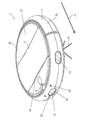
- FIG. 2 is a perspective view schematically showing the external appearance of the self-propelled cleaner 1 shown in FIG.
- the self-propelled cleaner 1 has a casing 2 having an air inlet 35 on the bottom surface and a dust collecting portion 31 inside, a pair of driving wheels 13 for running the casing 2, and rotation, stop and rotation of the driving wheels 13.
- a traveling control unit 12 that controls the direction and the like is provided, and autonomously performs a cleaning operation.
- the self-propelled cleaner 1 of the present invention mainly includes a control unit 11, a travel control unit 12, a drive wheel 13, a failure detection unit 14, a rechargeable battery 15, an operation input unit 17, and a voice input unit. 18, voice recognition unit 19, voice output unit 20, image acquisition unit 22, illumination unit 23, induction signal reception unit 24, charging connection unit 25, counter 27, communication unit 28, dust collection unit 31, ion generation unit 32, A ventilation control unit 33, an exhaust port 34, an intake port 35, and a storage unit 51 are provided.
- a self-propelled cleaner 1 of the present invention has a three-dimensional housing 2 such as a disk shape, a cylindrical shape, or a rectangular parallelepiped shape, and various components are arranged on the surface or inside of the housing 2.
- the driving wheel 13, the failure detection unit 14, the operation input unit 17, the voice input unit 18, the image acquisition unit 22, the illumination unit 23, the induction signal reception unit 24, and the charging connection unit 25 are arranged on the surface of the housing 2.
- the other components are provided inside the housing 2.
- the charging stand 100 is installed at a predetermined position in the room where cleaning is performed.
- the charging stand 100 may be installed at any location where power supply can be received, such as near a commercial power outlet, near a wall of a room, or beside a desk.
- the charging stand 100 includes a charging terminal unit 101 and an induction signal transmitting unit 102.
- the self-propelled cleaner 1 is supplied with electric power from the charging stand 100,
- the rechargeable battery 15 of the traveling vacuum cleaner 1 is charged.
- the self-propelled cleaner 1 performs a cleaning function while automatically traveling away from the charging stand 100.
- the self-propelled cleaner 1 of the present invention cleans the floor surface by sucking air containing dust on the floor surface and exhausting the air from which dust has been removed while traveling on the floor surface of the place where it is installed. It is a cleaning robot.
- the self-propelled cleaner 1 of the present invention has a function of autonomously returning to the charging stand 100 when cleaning is completed.
- the self-propelled cleaner 1 includes a disk-shaped housing 2, and a top plate 2 b, a side plate 2 c, a lid 3, a rotating brush, and a side brush are provided outside and inside the housing 2.
- a plurality of driving wheels 13 driven for self-propulsion a fault detection unit 14, an operation input unit 17, a voice input unit 18, a voice output unit 20, an image acquisition unit 22, an illumination unit 23, and a driven wheel.
- a front wheel and a rear wheel (not shown), an induction signal receiving unit 24, a communication unit 28 (not shown), a dust collecting unit 31 (not shown), an ion generating unit 32 (not shown), and an exhaust.
- An opening 34, an electric blower 36, and other components shown in FIG. 1 are provided.
- the part where the failure detection unit 14 is arranged is the front part of the casing 2
- the part where the lid part 3 is arranged is the middle part of the casing 2
- the opposite part across the middle part from the front part The part is called a rear part of the housing 2.
- the front is the traveling direction FD of the self-propelled cleaner 1 indicated by the arrow in FIG. 2
- the direction opposite to the traveling direction FD of the self-propelled cleaner 1 is the rear.
- the housing 2 takes in and out a circular bottom plate having a suction port 35 (see FIG. 1) provided on the back surface (lower surface) and provided with a rotating brush, and a dust collecting portion 31 accommodated in the housing 2.
- a top plate 2b having a lid 3 that opens and closes at the center is provided, and a side plate 2c having a ring shape in plan view provided along the outer periphery of the bottom plate and the top plate 2b.
- the bottom plate is formed with a plurality of holes for projecting the front wheels forward, the pair of drive wheels 13 in the middle, and the rear lower portion of the rear wheels from the inside of the housing 2 to the outside.
- An exhaust port 34 is formed in the vicinity of the boundary between the intermediate portion and the intermediate portion.
- the side plate 2c is divided into two parts in the front-rear direction, and the front part of the side plate 2c functions as a bumper.
- the self-propelled cleaner 1 detects the signal emitted from the induction signal transmission unit 102 of the charging stand 100 by the induction signal receiving unit 24 and recognizes the direction in which the charging stand 100 is present. For example, cleaning is completed. In this case, when the remaining charge of the rechargeable battery 15 is reduced, or when the set time of the set cleaning timer has elapsed, the vehicle travels autonomously on a route in a certain direction of the charging stand 100 and reaches the charging stand 100. Return. However, if there is an obstacle, it moves in the direction of the charging stand 100 while avoiding it.
- 1 is a part that controls the operation of each component of the self-propelled cleaner 1, and is mainly realized by a microcomputer including a CPU, a ROM, a RAM, an I / O controller, a timer, and the like.
- the CPU organically operates each hardware based on a control program stored in advance in a ROM or the like, and executes a detection function, a calculation function, a drive function, and the like as described later.
- the drive wheel 13 is a part which is arrange
- the travel control unit 12 is a part that controls the autonomous travel of the self-propelled cleaner 1, and is a part that mainly controls the rotation of the drive wheels 13 to cause the housing 2 to travel autonomously.
- the travel control unit 12 drives or stops the pair of drive wheels 13 to cause the self-propelled cleaner 1 to perform operations such as forward movement, backward movement, rotation, and stationary.
- the drive wheel 13 and the travel control unit 12 are an example of a travel unit according to the present invention.
- the obstacle detection unit 14 is a part that detects obstacles such as desks and chairs existing around the self-propelled cleaner 1, and for example, a distance measuring sensor including an ultrasonic sensor, an infrared distance measuring sensor, or the like is used. In the front part of the main body of the housing 2. A plurality of failure detection units 14 may be provided.
- the CPU related to the control unit 11 recognizes the position where the obstacle exists based on the signal output from the obstacle detection unit 14. Based on the position information of the recognized obstacle, a direction to travel next is determined while avoiding the obstacle.
- the self-propelled cleaner 1 may include a contact sensor that detects that the self-propelled cleaner 1 has come into contact with an obstacle.
- the rechargeable battery 15 is a part that supplies power to each functional element of the self-propelled cleaner 1, and is a part that mainly supplies power for performing a photographing function, travel control, and the like.
- a rechargeable battery such as a lithium ion battery, a nickel metal hydride battery, or a Ni—Cd battery is used.
- the rechargeable battery 15 is charged in a state where the self-propelled cleaner 1 and the charging stand 100 are connected.
- the connection between the self-propelled cleaner 1 and the charging stand 100 is performed by bringing the exposed connecting portion 25 for charging, which is a connecting portion, and the charging terminal portion 101 into electrical contact.
- the operation input unit 17 is a part where the user inputs an instruction for the operation of the self-propelled cleaner 1, and the surface of the case 2 of the self-propelled cleaner 1, for example, as shown in FIG.
- An operation panel or an operation button is provided on the upper surface panel at the rear.
- a remote control unit may be provided separately from the main body, an infrared ray or a radio wave signal may be transmitted by pressing an operation button provided on the remote control unit, and an operation instruction may be input by wireless communication.
- a power switch, a start switch, a charge request switch, and other switches (operation mode switch, timer switch) and the like are provided.
- the voice input unit 18 is a part for inputting a human voice or sound (hereinafter collectively referred to as voice), and a microphone is used, for example.
- voice a human voice or sound
- the voice input from the voice input unit 18 is, for example, AD converted and stored in the storage unit 51 as input voice data 54 in a predetermined digital voice format.
- the voice recognition unit 19 is a part that recognizes the input voice. That is, it is a part for recognizing a word or sentence included in the voice from the voice (input voice data 54) input from the voice input unit 18. Moreover, you may comprise as a part which specifies the person who uttered the sound.
- voice registration information 53 is stored in the storage unit 51 in advance.
- the voice registration information 53 is composed of, for example, a sample of voice data.
- the voice output unit 20 is a part that outputs voice for responding to the voice from the user, other voice for communication with the user, and the like, and a speaker is used.
- the audio output unit 20 is provided at a position on the side of the front surface of the housing 2 of the self-propelled cleaner 1. This is merely an example and can be provided at an arbitrary position.
- the voice recognition unit 19 performs pattern matching between the input voice data 54 and the voice data stored in the voice registration information 53. If the voice data of the voice registration information 53 includes voice data having a high degree of coincidence satisfying a predetermined determination criterion, the control unit 11 self-runs so as to execute a function associated with the voice data. Each component of the vacuum cleaner 1 is controlled. For example, when the input voice data 54 “clean” is input from the voice input unit 18, pattern matching between the input voice data 54 and a plurality of voice data stored in the voice registration information 53 is performed. A function (for example, a cleaning function) associated with the voice data determined to match the input voice data 54 is executed.
- a function for example, a cleaning function
- the image acquisition unit 22 is a part that acquires an image outside the housing 2, and for example, a camera is used. As shown in FIG. 2, for example, one image acquisition unit 22 is arranged in the housing 2 at the front part in the traveling direction when the vehicle travels normally. Two image acquisition units 22 may be provided on the front left and right sides of the housing 2 in order to measure the distance to the target.
- the image recognition unit 21 is a part that recognizes the acquired image. This is a part for recognizing and specifying a designated sign or person included in an image (acquired image data 56) acquired from an image acquisition unit 22 described later.
- the image acquired from the image acquisition unit 22 is AD converted, for example, and stored in the storage unit 51 as acquired image data 56 in a predetermined digital image format.
- the acquired image may be a still image or a moving image.
- the acquired still image is stored in the storage unit 51 as acquired image data 56.
- the illumination unit 23 is a part that illuminates the surroundings of the self-propelled cleaner 1, and, for example, an LED is used.
- the illumination unit 23 is lit in conjunction with the activation of the camera that is the image acquisition unit 22 and is turned on before photographing by the camera.
- the induction signal receiving unit 24 is an infrared sensor for receiving infrared rays, such as a beacon, and is disposed in the front part of the housing 2.
- the induction signal receiving unit 24 receives a position indicator signal (beacon) emitted from an induction signal transmission unit 102 such as an LED provided on the charging stand 100.
- an LED is used as the induction signal transmitting unit 102
- the radiation range of the position marker signal can be controlled by covering a part of the LED. For example, when an LED having a radiation angle of about 30 to 40 degrees is used, it is possible to realize the spread of a position indicator signal having a desired radiation angle by covering one side thereof.
- the counter 27 is a part that counts the encode signal based on the rotation angle of the motor that drives the drive wheels 13. In addition to the encoder based on the rotation angle of the motor, if the driving wheel 13 is driven by a pulse motor, the pulses may be counted. During the rotation of the drive wheel 13, the rotation angle is proportional to the count number CN measured by the counter 27, and if there is no slip between the drive wheel 13 and the floor surface, the travel distance of the housing 2 is driven. Since there is a proportional relationship with the rotation angle of the wheel 13 itself, the travel distance of the housing 2 can be estimated from the count number CN.
- the communication unit 28 is a part that communicates with an external device via a network. That is, it is a part that transmits various information to an external device other than the self-propelled cleaner 1, and a part that receives data such as an operation request from the external device.
- a network any network such as a wide area network (WAN) such as a LAN or the Internet, or a dedicated communication line may be used.
- WAN wide area network
- the wireless communication standard include Bluetooth (registered trademark) and IEEE802.11a, IEEE802.11b, IEEE802.11g, and IEEE802.11n, which are wireless LAN standards.
- the communication unit 28 transmits the acquired image data 56 acquired by the image acquisition unit 22 to the external device.
- the external device include a PC (not shown), a portable terminal, and a server.
- the dust collection unit 31 is a part that performs a cleaning function to collect indoor garbage and dust, and mainly includes a dust collection container (not shown), a filter unit, and an openable / closable cover unit that covers the dust collection container and the filter unit.
- the dust collection unit 31 has an inflow path that communicates with the intake port 35 and an exhaust path that communicates with the exhaust port 34, and air sucked from the intake port 35 passes through the inflow path into the dust collecting container. And is discharged from the exhaust port 34 to the outside through the filter portion and the discharge path.
- the ventilation control part 33 which drives the electric blower 36 and the electric blower 36 is provided.
- the dust collecting unit 31 is not controlled by the control unit 11, and detection means (mechanical switch, light detection switch) for detecting whether the dust collecting unit 31 is housed in the housing unit of the cleaner body. Etc.) is shown as being sent to the control unit 11.
- the ion generator 32 is a part that is accommodated in the housing 2 and generates ions. Specifically, water molecules in the air are ionized by discharge, and H + (H 2 O) m (m is an arbitrary natural number) as positive ions and O 2 ⁇ (H 2 O) n (n is a negative ion). Any natural number).
- the ion generation part 32 has each ion discharge
- the ions to be generated are not particularly limited, and examples thereof include ions capable of purifying air, ions having a skin beautifying effect and an effect of suppressing bacterial growth on the skin surface, and the like.
- plasma cluster ions registered trademark
- the ion generator 32 is provided as, for example, a small rectangular parallelepiped ion generator.
- the generated ions may be either negative ions or positive ions.
- you may include the charged fine particle water droplet obtained using an electrostatic atomization phenomenon. In particular, when negative ions are generated, a relaxing effect can be given to the user.
- the air blow control unit 33 mainly drives and controls a blower fan for performing air intake from the air intake port 35. Ions generated by the ion generation unit 32 are released into clean air that has passed through the filter unit of the dust collection unit 31, and are blown out from the exhaust port 34 together with the air.
- the exhaust port 34 is, for example, an opening that is provided at a position on the upper surface of the housing 2 and discharges air containing ions generated by driving the ion generation unit 32 to the outside. Further, the air containing ions may be emitted from the upper surface of the housing 2 to the rear and slightly upward.
- the self-propelled cleaner 1 sucks the dust on the floor surface together with the outside air through the air inlet 35, separates the dust at the dust collecting unit 31, and then exhausts the air from which the dust has been removed. Since it discharges
- the self-propelled cleaner 1 and the self-propelled ion generator that does not have a cleaning function may be provided on the top plate 2b side as the inlet 35 instead of the bottom plate.
- a filter unit that removes dust contained in the air in the path from the intake port 35 to the exhaust port 34 without the dust collection unit 31.
- an exhaust opening / closing lid is provided at the exhaust port 34 in order to prevent foreign matter, dust, etc. from entering the inside from at least the exhaust port 34 except when ions are generated. Yes.
- An intake opening / closing lid that opens and closes the intake port 35 is also provided in the intake port 35 as necessary.
- the above ion generator is not provided with the ion generator 32, but is provided with a filter unit that removes and purifies dust contained in the air in the path from the intake port 35 to the exhaust port 34, and a blower fan is provided.
- An air cleaner that purifies air by driving can also be configured. Needless to say, these are functions and devices that are included in the present invention.
- the storage unit 51 is a part for storing information and programs necessary for realizing various functions of the self-propelled cleaner 1, and is used by a storage element such as a semiconductor element such as RAM or ROM, a hard disk, or a flash memory. It is done.
- the storage unit 51 mainly stores traveling characteristic information 52, input voice data 54, acquired image data 56, and the like. In addition, information necessary for executing functions such as voice recognition, photographing, communication, and other functions is temporarily stored.
- the travel characteristic information 52 is data relating to the travel characteristics of the housing 2, for example, data on the position coordinates of the housing 2, the travel distance, the count number CN, and the rotation angle at the time of turning.
- the travel distance or rotation angle of the housing 2 is stored in the travel characteristic information 52 together with the count number CN required for travel or rotation. In this way, the travel history of the self-propelled cleaner 1 can be stored.
- the storage unit 51 is an example of a travel history holding unit according to the present invention.
- the voice registration information 53 is information stored in advance in association with a word to be recognized, voice data of the word, and information for specifying the name of the person who issued the voice data when performing voice recognition.
- One voice registration information 53 stores a registered word, voice data, and the name of the person who uttered the voice data in association with each other.
- it is necessary to register the person name to specify a person.
- the voice data for example, digital information such as a voice analog waveform itself, waveform information, frequency information, a voice library, and registered word information is stored as one voice file.
- the input voice data 54 is voice or sound data input from the voice input unit 18 and is, for example, digitized acoustic data.
- the acquired image data 56 is an image acquired by the image acquisition unit 22. The image may be either a still image or a moving image.
- FIG. 3 is a flowchart of the preparation operation process of the self-propelled cleaner 1 of the present invention.
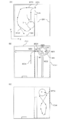
- FIG. 4 is an explanatory diagram showing a preparation operation procedure of the self-propelled cleaner 1 of the present invention. 4B and 4C, reference numerals common to those in FIG. 4A are omitted.
- Embodiment 1 demonstrates the method of determining the cleaning area
- step S1 of FIG. 3 the control unit 11 advances the housing 2 (step S1).
- the casing 2 of the self-propelled cleaner 1 is connected to the charging stand 100 installed on the side wall SW, and the induction signal of the charging stand 100
- the route RT1 indicated by the arrow is moved along the guidance signal transmitted from the transmission unit 102.
- the self-propelled cleaner 1 does not necessarily need to move a path
- a rectangular room surrounded by the sidewall SW is assumed, and an inner wall along the Y-axis direction is formed in the middle of the room.
- a direction along the side wall SW on which the charging stand 100 is installed is defined as an X-axis direction
- a direction perpendicular to the X-axis direction is defined as a Y-axis direction.
- step S2 the control unit 11 determines whether or not the failure detection unit 14 has detected an obstacle in front of the housing 2 (step S2).
- step S2 the control unit 11 proceeds to step S3.
- step S4 the control unit 11 proceeds to step S4.
- step S3 the control unit 11 determines whether or not the housing 2 has advanced a predetermined distance (for example, 2 m) from the charging stand 100 (step S3).
- a predetermined distance for example, 2 m
- the control unit 11 proceeds to step S4.
- the control unit 11 returns to step S1.
- step S4 the control unit 11 stops the casing 2 in order to detect surrounding obstacles (step S4).
- the detection position is not limited to one, and an obstacle may be detected at a plurality of positions.
- an obstacle may be detected at a plurality of positions.
- step S5 the control unit 11 causes the obstacle detection unit 14 to detect the direction in front of the housing 2 and the distance from the housing 2 to the obstacle, and stores the detected information in the storage unit 51 (step S5).
- the control unit 11 uses the direction in which the housing 2 has advanced along the path RT1 (the Y-axis positive direction) as the reference direction to control the housing 2 from the failure detection unit 14.
- the distance L1 to the obstacle ahead is stored in the storage unit 51.
- step S6 the control unit 11 changes the direction of the housing 2 by 90 ° clockwise from the reference direction (step S6).
- the housing 2 is turned 90 ° clockwise (RD direction) from the reference direction (Y-axis positive direction).
- step S7 the control part 11 determines whether the housing
- the control unit 11 proceeds to step S8.
- the control unit 11 returns to step S5 and continues to detect the obstacle.
- the control unit 11 detects the failure in front of the housing 2 from the direction and the failure detection unit 14.
- the distance L2 to the object is stored in the storage unit 51.
- the control unit 11 determines the direction and the distance from the obstacle detection unit 14 to the obstacle in front of the housing 2.
- L3 is stored, and when the housing 2 is oriented 270 ° from the reference direction (X-axis negative direction), the direction and the distance L4 from the obstacle detection unit 14 to the obstacle in front of the housing 2 are stored. Stored in the unit 51.
- Table 1 below shows an example of the results detected in this way.
- the detection direction is the direction seen from the front of the housing 2, and is represented by the directions of arrows MD1 to MD4 in FIG.
- the rotation angle represents an angle based on the direction (the direction along the route RT1 in FIG. 4A) in which the housing 2 has left the charging stand 100 and advanced to the cleaning region.
- the distance to the obstacle represents the distance (m) from the obstacle detection unit 14 to the obstacle in front of the housing 2.
- the distance to the obstacle is L1
- the housing 2 is of the arrow MD2.
- the distance to the obstacle is L2
- the housing 2 faces the arrow MD3 direction (Y-axis negative direction, rotation angle 180 °).
- the distance to the obstacle is L3
- the casing 2 faces the direction of the arrow MD4 (X-axis negative direction, rotation angle 270 °)
- the distance to the obstacle is L4.
- the rotation angle of the direction change of the housing 2 does not need to be in units of 90 ° as shown in FIG. 4B, and may be set to an arbitrary rotation angle.
- the direction of the housing 2 may be changed in units of 45 °.
- a plurality of obstacle detection units 14 may be provided on the side surface of the housing 2 to detect obstacles in a plurality of directions at a time.
- three obstacle detection units 14 having a detection angle different by 40 ° may be provided in the front part of the housing 2, and obstacles in three directions may be detected at the same time. Further, it is not always necessary to change the direction of the casing 2 in order to detect an obstacle.
- the obstacle detection unit 14 is provided on the front, rear, left, and right sides of the casing 2 so You may make it detect the distance of an obstruction at once.
- the image recognition unit 21 may analyze the image acquired by the image acquisition unit 22 to detect the distance and direction to the obstacle. Further, in the case where the casing 2 performs detection by moving a predetermined distance from the charging stand 100, detection in the direction from the casing 2 toward the charging stand 100 may be omitted. Further, when the room is symmetrical and the charging stand 100 is installed at the center of the side wall, the detection may be performed only in the left or right direction of the room as viewed from the charging stand 100.
- step S8 the control unit 11 estimates the area of the cleaning area to be self-run based on the detection results in steps S5 to S7 (step S8).
- step S9 the control unit 11 determines the travel time of the self-propelled cleaner 1 from the start of cleaning to the start of return to the charging stand 100 based on the estimated area of the cleaning region (step S9).
- the control unit 11 determines, for example, by referring to the correspondence relationship between the estimated area (m 2 ) of the cleaning area and the travel time (minutes) as shown in Table 3 below.
- the estimated area EA1 is about 24 (m 2 )
- the estimated area is between 20 and 30 (m 2 ). Recognize.
- the correspondence relationship in Table 3 indicates that when the self-propelled cleaner 1 is self-propelled in a room of each estimated area, for example, the self-propelled cleaner 1 covers 99% or more of the indoor area. It can be calculated from the average time required to travel.
- the estimated area may be determined based on the size of a Japanese room such as 4 tatami mats, 6 tatami mats, and 8 tatami mats.
- control unit 11 starts a cleaning operation, and causes the housing 2 to travel by random travel during the travel time.
- the self-propelled cleaner 1 self-runs in the cleaning area CA1 by random running, and returns to the charging stand 100 when the running time elapses.
- the rectangular cleaning area CA1 is assumed.
- an elliptical similarity area CA1 may be assumed as illustrated in FIG.
- the position of the obstacle is detected by measuring a number of directions (eight directions MD1 to MD8 in FIG. 4C) while rotating the housing 2, and the elliptical cleaning is performed based on the detected position.
- a region CA1 is determined.
- the travel time is determined based on the area of the elliptical cleaning area CA1.
- a more realistic cleaning area CA1 considering an area in which the housing 2 can self-run as compared to a rectangular cleaning area CA1. Can be determined.
- FIG. 5 is a flowchart of the cleaning operation process of the self-propelled cleaner 1 of the present invention.
- FIG. 6 is an explanatory diagram showing a cleaning operation procedure of the self-propelled cleaner 1 of the present invention. 6B and 6C, reference numerals common to those in FIG. 6A are omitted.
- Embodiment 2 the operation when the self-propelled cleaner 1 goes out of the cleaning area CA1 during self-running in random running will be described.
- the control unit 11 follows the procedure shown in the following steps.
- control part 11 makes the housing
- step S12 the control unit 11 determines whether or not the casing 2 has moved out of the cleaning area during self-running (step S12).
- the determination as to whether or not the housing 2 has gone out of the cleaning area may be made by calculating coordinates based on the charging stand 100. For example, as shown in FIG. 6A, assuming a charging area 100 as a reference (origin), a rectangular cleaning area CA1 of ⁇ 2 m to +2 m in the X-axis direction and +0 m to +6 m in the Y-axis direction is assumed.
- the position coordinates of the self-running casing 2 are out of the range of the (X, Y) coordinates of the cleaning area CA1, it is determined that the casing 2 has moved out of the cleaning area CA1.
- step S12 when the housing
- step S16 the control unit 11 determines whether or not the travel time determined in the preparation operation has elapsed (step S16).
- the control unit 11 returns the housing 2 to the charging stand 100.
- the traveling time has not elapsed (when the determination in step S16 is No)
- the control unit 11 proceeds to step S17.
- the housing 2 of the self-propelled cleaner 1 self-travels along a route RT11 in the cleaning area CA1.
- the self-propelled cleaner 1 continues self-propelled during the travel time, but travels on a route RT12 that ends random travel and returns to the charging stand 100 as soon as the travel time elapses.
- step S13 the control part 11 measures the length (dLX, dLY) of the path
- the housing 2 runs out of the cleaning area CA1 and travels along the route RT13 and protrudes 2 m from the cleaning area CA1 in the positive direction of the X axis.
- the length (dLX, dLY) of the path protruding in the (X, Y) direction is (2m, 0).
- control unit 11 estimates the area of the new cleaning region based on the length (dLX, dLY) measured in step S13 (step S14).
- the diameter of the housing 2 is set to LD (m).
- LD m
- step S15 the control unit 11 corrects the travel time until the start of feedback based on the updated cleaning region (step S15). Specifically, based on the updated size of the cleaning area, a new travel time is obtained from the correspondence relationship in Table 3.
- EA1 (LD + L2 + L4 + dLX) ⁇ (LD + L1 + L3 + dLY).
- the traveling time may be 50 minutes. Recognize. Therefore, the traveling time of the self-propelled cleaner 1 is updated from the traveling time 40 minutes corresponding to the immediately preceding cleaning area CA1 to the traveling time 50 minutes corresponding to the new cleaning area CA2.
- the self-propelled cleaner 1 since the self-propelled cleaner 1 according to the second embodiment updates the cleaning area every time the casing 2 enters a new area during self-propelling, based on the area of the updated cleaning area, The travel time can be corrected in real time.
- step S17 the control unit 11 refers to the remaining battery level of the self-propelled cleaner 1 to check whether the remaining battery level is sufficient (step S17). If the remaining battery level is sufficient (if the determination in step S17 is Yes), the control unit 11 returns to step S11 and continues the cleaning operation of the self-propelled cleaner 1 continuously. On the other hand, when the battery remaining amount is not sufficient (when the determination in step S17 is No), the control unit 11 returns the housing 2 to the charging stand 100.
- the self-propelled cleaner 1 travels along a random route RT14 in a rectangular cleaning area CA3 as shown in FIG.
- the estimated area of the cleaning area CA3 is about 42 (m 2 )
- the traveling time is 60 minutes.
- the size of the estimated area may be estimated in consideration of the length of the sidewall SW existing between the two cleaning areas.
- the self-propelled cleaner 1 immediately travels on a route RT15 that ends random running and returns to the charging stand 100. To do.
- the self-propelled cleaner 1 explained the case where the estimated area and the travel time are corrected based on the length of the protruding path. Not limited to that.
- the estimated area and the traveling time may be corrected based on the time when the vehicle has gone out of the traveling region.
- FIG. 7 is a flowchart of the cleaning operation process of the self-propelled cleaner 1 of the present invention.
- FIG. 8 is an explanatory diagram showing a cleaning operation procedure of the self-propelled cleaner 1 of the present invention. 8B and 8C, reference numerals common to those in FIG. 8A are omitted.
- the control unit 11 follows the procedure shown in the following steps.
- step S21 of FIG. 7 the control unit 11 causes the housing 2 to self-run in random travel (step S21).
- step S22 the control part 11 determines whether the housing
- step S21 the determination in step S21 is Yes
- the control unit 11 proceeds to step S23.
- step S22 the control unit 11 proceeds to step S26.
- step S23 the control part 11 determines whether the housing
- the control part 11 progresses to step S24.
- the control part 11 progresses to step S25.
- whether or not a new cleaning area has been entered can be determined based on whether or not the current coordinates of the housing 2 are within the range of the cleaning area that has been the object of cleaning so far.
- step S24 the control unit 11 records the current coordinates and direction of the housing 2 in the storage unit 51 (step S24).
- step S25 the control unit 11 returns to the previous cleaning area (step S25).
- the case 2 is moved forward by 180 ° after changing its direction on the spot, or the case 2 is moved backward and then turned left and right. And returning to the previous cleaning area.
- the housing 2 may not enter the new cleaning area during the self-running.
- step S26 the control unit 11 determines whether or not the traveling time has elapsed (step S26).
- the control unit 11 proceeds to step S28.
- the traveling time has not elapsed (when the determination in step S26 is No)
- the control unit 11 proceeds to step S27.
- step S27 the control unit 11 refers to the remaining battery level of the self-propelled cleaner 1, and checks whether the remaining battery level is sufficient (step S27). When the remaining battery level is sufficient (when the determination in step S27 is Yes), the control unit 11 returns to step S21 and continues the cleaning operation of the self-propelled cleaner 1 continuously. On the other hand, when the battery remaining amount is not sufficient (when the determination in step S27 is No), the control unit 11 returns the housing 2 to the charging stand 100.
- step S28 the control unit 11 determines whether or not a new cleaning area exists (step S28).
- step S28 determines whether or not a new cleaning area exists (when the determination in step S28 is Yes).
- step S29 the control unit 11 proceeds to step S29.
- step S28 determines whether or not a new cleaning area exists (when determination in step S28 is Yes).
- step S29 the control part 11 returns the housing
- step S29 the control unit 11 refers to the remaining battery level of the self-propelled cleaner 1, and checks whether the remaining battery level is sufficient (step S29). If the remaining battery level is sufficient (if the determination in step S29 is Yes), the control unit 11 proceeds to step S30. On the other hand, when the battery remaining amount is not sufficient (when the determination in step S29 is No), the control unit 11 returns the housing 2 to the charging stand 100.
- step S30 the control unit 11 refers to the current position coordinates of the housing 2 and the position coordinates of the new cleaning area stored in the storage unit 51, and determines the distance to the new cleaning area and The direction is calculated and the casing 2 is moved toward a new cleaning area.
- the control unit 11 when the end of the travel time of the cleaning area CA1 approaches, the control unit 11 causes the housing 2 to travel along a route RT24 along the side wall SW. By running along the wall in this way, a new cleaning area can be reliably found. Thereafter, the control unit 11 returns to step S1 to execute a preparatory operation in a new cleaning area.
- the self-propelled cleaner 1 uses the recorded coordinates and directions. Referring to the new cleaning area CA4 (route RT24). After entering the new cleaning area CA4, the self-propelled cleaner 1 moves forward in the new cleaning area as in the case of the first embodiment and detects an obstacle in front of the housing 2, or Stop after moving a predetermined distance in the new cleaning area CA4 (after traveling on the route RT25, the housing 2 is stopped at the reference point CP2).
- the self-propelled cleaner 1 changes the direction of the housing 2 in units of 90 °, estimates the estimated area of the new cleaning area CA4, and determines the travel time based on the estimated area. To do. Thereafter, as shown in FIG. 8C, the self-propelled cleaner 1 self-propels in the new cleaning area CA4 by random travel (route RT26).
- FIG. 9 is an explanatory diagram showing a cleaning operation procedure of the self-propelled cleaner 1 of the present invention. 9B, reference numerals common to those in FIG. 9A are omitted.
- the control unit 11 causes the self-propelled cleaner 1 to pass through the area of the induction signal BS radiated from the induction signal transmission unit 102 of the charging stand 100. Detect the number of times
- the induction signal BS is radiated from the charging stand 100 installed on the side wall SW at a constant radiation angle in the Y-axis direction (shaded portion in FIG. 9).
- the self-propelled cleaner 1 self-travels in the cleaning area CA1 along a random route RT31, and counts the number of times the induction signal BS is detected each time the induction signal receiver 24 passes through the area of the induction signal BS.
- the control unit 11 returns the self-propelled cleaner 1 to the charging stand 100.
- the control unit 11 determines, for example, with reference to a table showing the correspondence between the estimated size (m 2 ) of the cleaning area and the minimum number of detections (times) as shown in Table 5 below. .
- the minimum number of detections is 10.
- the minimum number of detections is 20 times.
- the correspondence relationship in Table 5 is that when the charging stand 100 is installed at the center of the wall surface of the room so that the induction signal BS crosses the room of an arbitrary size and the self-propelled cleaner 1 is self-running in random running, for example, It can be obtained by counting the average minimum number of detections required for the self-propelled cleaner 1 to travel in an area of 99% or more of the indoor area.
- a self-propelled cleaner detects a position of a housing, a traveling unit that travels the housing, a cleaning unit that cleans the floor, and an obstacle around the housing.
- a fault detection unit and a control unit that controls the travel unit, the cleaning unit, and the fault detection unit to perform cleaning while allowing the casing to self-run, and the control unit is arranged around the fault detection unit.
- the position of the obstacle is detected, and the traveling time for cleaning is determined based on the position of the obstacle.
- the “self-propelled cleaner” refers to a housing having an air inlet on the bottom and a dust collecting portion inside, a drive wheel for running the housing, rotation, stop and rotation direction of the drive wheel, etc.
- the “obstacle detection unit” is provided in a self-propelled cleaner and detects obstacles such as walls and furniture around the self-propelled cleaner.
- the specific mode is, for example, a position where an obstacle sensor such as an ultrasonic sensor or an infrared distance measuring sensor is mounted on the front part of the housing of the self-propelled cleaner, and is separated from a surrounding obstacle by a predetermined distance.
- the direction and the distance may be held by acquiring the distances to surrounding obstacles in a plurality of directions while changing the direction of the case by 360 °.
- a plurality of obstacle sensors facing different directions may be mounted on each part of the side surface of the housing of the self-propelled cleaner, and obstacles in a plurality of directions may be measured simultaneously.
- the self-propelled cleaner may be equipped with a camera and acquire and hold the direction and distance of the obstacle from an image taken by the camera.
- a combination of these may also be used.
- the obstacle is not necessarily an actual object, and may be an electronic obstacle made from a virtual wall signal, for example.
- the “running time during which the housing can self-run” is, for example, an area of 99% or more of the indoor area when the self-propelled vacuum cleaner is self-propelled in a room. This is the average time required for the self-propelled cleaner to travel.
- the specific aspect is required, for example, when the self-propelled vacuum cleaner travels in a predetermined ratio area when the self-propelled vacuum cleaner is allowed to self-propelled in a room of an arbitrary area.
- Data of average required time may be stored in advance in the self-propelled cleaner, and the travel time may be determined by referring to the stored data. Alternatively, the travel time may be determined by the control unit based on a predetermined algorithm.
- control unit may determine a travel region in which the housing can self-propell based on the position of the obstacle.
- the “running region in which the housing can self-run” is, for example, a rectangular or (elliptical) circular region surrounding the housing. Further, the traveling area may be triangular, square, polygonal, or other shapes. When the travel area is polygonal, the travel area in which the housing can travel is a polygonal area surrounded by a line connecting the positions of a plurality of obstacles surrounding the housing.
- control unit corrects the travel time when the casing that is self-propelled in the travel region goes out of the travel region. Also good.
- the distance traveled by the casing outside the traveling area and / or The travel area and the travel time may be corrected based on time.
- the self-propelled vacuum cleaner is self-propelled in a complex area of the room layout, it travels by sequentially determining each traveling area and traveling time. A self-propelled cleaner that travels reliably can be realized.
- the obstacle detection unit when the casing that is self-propelled in the traveling area comes out of the traveling area, the obstacle detection unit has the obstacle around the obstacle detecting section.
- the travel time may be corrected based on the position of the obstacle.
- the self-propelled cleaner further includes an induction signal receiving unit that receives an induction signal emitted from the charging stand at a predetermined radiation angle, and the control unit is self-propelled of the casing.
- the control unit is self-propelled of the casing.
- the self-propelled vacuum cleaner can finish the self-running of the housing at an appropriate timing even if the room layout is complicated and the shape and area of the entire travel area cannot be accurately grasped. Can be realized.
- a device such as a gyro sensor and a camera and a complicated function such as a mapping function are not necessary, so that the cost can be reduced.
- Preferred embodiments of the present invention include combinations of any of the above-described plurality of embodiments.
- various modifications of the present invention are possible. These modifications should not be construed as not belonging to the scope of the present invention.
- the present invention should include the meaning equivalent to the scope of the claims and all modifications within the scope.
Landscapes
- Engineering & Computer Science (AREA)
- Mechanical Engineering (AREA)
- Physics & Mathematics (AREA)
- General Physics & Mathematics (AREA)
- Aviation & Aerospace Engineering (AREA)
- Radar, Positioning & Navigation (AREA)
- Remote Sensing (AREA)
- Automation & Control Theory (AREA)
- Multimedia (AREA)
- Electromagnetism (AREA)
- Computer Vision & Pattern Recognition (AREA)
- Electric Vacuum Cleaner (AREA)
- Control Of Position, Course, Altitude, Or Attitude Of Moving Bodies (AREA)
- Robotics (AREA)
Abstract
Description
<自走式掃除機の構成>
この発明の実施形態1に係る自走式掃除機1について説明する。
以下、図1及び図2に基づき、この発明の自走式掃除機1の構成を説明する。
図1は、この発明の自走式掃除機1及び充電台100の概略構成を示すブロック図である。
図2は、図1に示す自走式掃除機1の外観を概略的に示す斜視図である。
自走式掃除機1は、底面に吸気口35を有すると共に内部に集塵部31を有する筐体2、筐体2を走行させる一対の駆動輪13、並びに駆動輪13の回転、停止及び回転方向等を制御する走行制御部12を備え、自律的に掃除動作する。
この発明の自走式掃除機1は、例えば円盤形、円柱形、あるいは直方体形等の立体形状の筐体2を有し、その筐体2の表面や内部に、各種構成要素が配置される。
例えば、上記した駆動輪13、障害検知部14、操作入力部17、音声入力部18、画像取得部22、照明部23、誘導信号受信部24及び充電用接続部25は、筐体2の表面の外部から視認できる位置に設けられ、その他の構成要素は筐体2の内部に設けられる。
図2において、障害検知部14が配置されている部分を筐体2の前方部、蓋部3が配置されている部分を筐体2の中間部、前方部から中間部を挟んで反対側の部分を筐体2の後方部とそれぞれ呼ぶ。ここで、前方とは、図2の矢符で示す自走式掃除機1の進行方向FDであり、自走式掃除機1の進行方向FDと逆向きの方向を後方とする。
図1の制御部11は、自走式掃除機1の各構成要素の動作を制御する部分であり、主として、CPU、ROM、RAM、I/Oコントローラ、タイマー等からなるマイクロコンピュータによって実現される。
CPUは、ROM等に予め格納された制御プログラムに基づいて、各ハードウェアを有機的に動作させて、後述するようなこの発明の検知機能、算出機能、駆動機能などを実行する。
走行制御部12は、自走式掃除機1の自律走行の制御を行う部分であり、主として駆動輪13の回転を制御して筐体2を自律的に走行させる部分である。
走行制御部12は、一対の駆動輪13を駆動又は停止させることにより、自走式掃除機1の前進、後退、回転、静止などの動作を行わせる。ここで、駆動輪13及び走行制御部12は、本発明に係る走行部の一例である。
制御部11にかかるCPUは、障害検知部14から出力された信号に基づいて、障害物の存在する位置を認識する。認識された障害物の位置情報に基づいて、その障害物を回避して次に走行すべき方向を決定する。
なお、自走式掃除機1は、障害検知部14に加えて、自走式掃除機1が障害物に接触したことを検知する接触センサを備えてもよい。
充電池15の充電は、自走式掃除機1と充電台100とを接続した状態で行われる。
自走式掃除機1と充電台100との接続は、接続部である露出した充電用接続部25と充電端子部101とを電気的に接触させることにより行う。
本体とは別にリモコンユニットを設け、リモコンユニットに設けられた操作ボタンを押すことによって赤外線や無線電波信号を送出し、無線通信により動作の指示入力をしてもよい。
操作入力部17としては、例えば、電源スイッチ、起動スイッチ、充電要求スイッチ、その他のスイッチ(運転モードスイッチ,タイマスイッチ)などが設けられる。
音声入力部18から入力された音声は、例えば、AD変換され、所定のデジタル音声フォーマットで、入力音声データ54として記憶部51に記憶される。
例えば、音声入力部18から、「きれいにして」という入力音声データ54が入力された場合、その入力音声データ54と音声登録情報53に予め記憶されている複数の音声データとのパターンマッチングを行い、入力音声データ54と一致すると判定された音声データに対応づけられた機能(例えば、掃除機能など)を実行する。
取得する画像は、静止画であっても動画であってもよい。取得された静止画は、取得画像データ56として記憶部51に記憶される。
誘導信号送信部102としてLEDを用いる場合、その一部に蓋をすることで、位置標識信号の放射範囲を制御することもできる。例えば、約30~40度の放射角を有するLEDを用いる場合、その片側を覆うことで所望の放射角の位置標識信号の広がりを実現できる。
ネットワークとしては、LAN、インターネットなどの広域ネットワーク(WAN)、専用の通信回線などいずれのネットワークを利用してもよい。
その無線通信規格としては、例えば、Bluetooth(登録商標)や無線LANの標準規格であるIEEE802.11a、IEEE802.11b、IEEE802.11g、IEEE802.11n等が挙げられる。
例えば、外部装置から画像撮影要求が受信された場合など、所定の画像送信条件が満たされた場合に、通信部28が、画像取得部22によって取得した取得画像データ56を外部装置へ送信する。外部装置としては、例えば、図示しないPC、携帯端末、サーバなどがある。
また、集塵部31は、吸気口35と連通する流入路と、排気口34と連通する排出路とを有し、吸気口35から吸い込まれた空気は、流入路を介して集塵容器内に導かれ、フィルタ部及び排出路を介して排気口34から外部へ放出される。また、空気を流通させるために電動送風機36及び電動送風機36を駆動する送風制御部33が設けられている。
なお、集塵部31は、制御部11にて制御されるものでなく、集塵部31が掃除機本体の収容部に収容されたか否かを検知する検知手段(機械式スイッチ、光検知スイッチ等)の検知信号を、制御部11へ送るものとして図示している。
具体的には、放電により空気中の水分子を電離し、正イオンとしてH+(H2O)m(mは任意の自然数)、負イオンとしてO2 -(H2O)n(nは任意の自然数)を生成する。
イオン発生部32は、排気経路に臨む部分に、正負のイオンを生成する場合、それぞれのイオン放出部を有している。
なお、発生するイオンは、負イオン又は正イオンのどちらかでもよい。また、静電霧化現象を利用して得られる帯電した微粒子水滴を含んでもよい。特に、負イオンを発生する場合には、ユーザーにリラックス効果を与えることができる。
イオン発生部32で発生したイオンは、集塵部31のフィルタ部を通過した清浄な空気中に放出され、該空気と共に排気口34から外部へ吹き出される。
記憶部51には、主として、走行特性情報52、入力音声データ54、取得画像データ56などが記憶される。その他、音声認識、撮影、通信などの機能、その他の機能を実行するときに必要な情報が一時的に記憶される。
筐体2の走行距離又は回転角度は、走行又は回転に要したカウント数CNとともに走行特性情報52に記憶される。
このようにして、自走式掃除機1の走行履歴を記憶することができる。ここで、記憶部51は、本発明に係る走行履歴保持部の一例である。
1つの音声登録情報53は、登録単語と、音声データと、その音声データを発声した人物名とが予め対応付けられて記憶される。
ただし、人物を特定する場合は、人物名を登録しておく必要があるが、不特定多数の人が発声した単語認識のみを行い、人物の特定をしない場合は、人物名は登録しなくてもよい。
音声データとしては、例えば、音声のアナログ波形そのものや、波形情報、周波数情報、音声ライブラリ、登録単語情報などのデジタル情報が、1つの音声ファイルとして記憶される。
取得画像データ56は、画像取得部22によって取得された画像である。画像としては、静止画あるいは動画のどちらでもよい。
次に、図3及び図4に基づき、自走式掃除機1の準備動作手順の具体例について説明する。
図3は、この発明の自走式掃除機1の準備動作処理のフローチャートである。
図4は、この発明の自走式掃除機1の準備動作手順を示す説明図である。
図4(B)(C)において、図4(A)と共通部分の符号は省略する。
準備動作の開始後、制御部11は、以下のステップに示す手順に従う。
図4(A)において、側壁SWに囲まれた矩形状の室内を想定し、室内の中間にはY軸方向に沿った内壁が形成されている。ここで、充電台100が設置された側壁SWに沿った方向をX軸方向とし、X軸方向に垂直な方向をY軸方向とする。
図6,図8及び図9においても同様である。
障害検知部14が筐体2の前方に障害物を検知しなかった場合(ステップS2の判定がNoの場合)、制御部11は、ステップS3へ進む。
一方、障害検知部14が筐体2の前方に障害物を検知した場合(ステップS2の判定がYesの場合)、制御部11は、ステップS4へ進む。
筐体2が充電台100から所定距離だけ進んだ場合(ステップS3の判定がYesの場合)、制御部11は、ステップS4へ進む。
一方、筐体2が充電台100から所定距離進んでいない場合(ステップS3の判定がNoの場合)、制御部11は、ステップS1へ戻る。
このとき、図4(A)に示すように、筐体2が経路RT1に沿って前進した方向(Y軸正方向)を基準方向として、制御部11は、障害検知部14から筐体2の前方の障害物までの距離L1を記憶部51に保存する。
このとき、図4(B)に示すように、筐体2は基準方向(Y軸正方向)から右回り(RD方向)に90°方向転換する。
筐体2が基準方向から360°方向転換している場合(ステップS7の判定がYesの場合)、制御部11は、ステップS8へ進む。
一方、筐体2が基準方向から360°方向転換していない場合(ステップS7の判定がNoの場合)、制御部11は、ステップS5に戻り、障害物の検知を続行する。
同様に、筐体2が基準方向から180°の方向(Y軸負方向)を向いているとき、制御部11は、その方向及び障害検知部14から筐体2の前方の障害物までの距離L3を、そして、筐体2が基準方向から270°の方向(X軸負方向)を向いているとき、その方向及び障害検知部14から筐体2の前方の障害物までの距離L4を記憶部51に保存する。

また、筐体2の側面に複数の障害検知部14を設け、一度に複数の方向の障害物を検知するようにしてもよい。例えば、筐体2の前部に検知角が40°異なる障害検知部14を3つ設け、同時に3方向の障害物を検知するようにしてもよい。
また、障害物を検知するために筐体2を必ずしも方向転換させる必要はなく、例えば、筐体2の前後左右に障害検知部14を設け、筐体2を方向転換させることなく前後左右方向の障害物の距離を一度に検知するようにしてもよい。また、障害検知部14を用いる代わりに、画像取得部22で取得した画像を画像認識部21で分析することによって、障害物までの距離及び方向を検知するようにしてもよい。
また、筐体2が充電台100から所定の距離だけ進んで検知を行う場合は、筐体2から充電台100に向かう方向への検知を省略してもよい。また、部屋が対称形であって、充電台100が側壁の中央に設置されている場合は、充電台100から見て部屋の左右いずれかの方向の検知だけをするものであってもよい。

例えば、図4(B)に示すような矩形状の掃除領域CA1の場合、その推定面積EA1は、X軸方向の長さ×Y軸方向の長さ、すなわち、EA1=(LD+L2+L4)×(LD+L1+L3)である。ここで、推定面積EA1が約24(m2)であった場合、推定面積が20~30(m2)の間にあるため、表3の対応関係から、走行時間が40分であることがわかる。

また、4畳半、6畳、8畳といった和室の広さを単位として推定面積を定めてもよい。
このとき、自走式掃除機1は、掃除領域CA1内をランダム走行で自走し、走行時間が経過すると充電台100に帰還する。
次に、実施形態1の変形例について説明する。
実施形態1において、矩形状の掃除領域CA1を想定したが、実施形態1の変形例においては、図4(C)に示すように、楕円形状の相似領域CA1を想定してもよい。この場合、筐体2を回転させながら多数の方向(図4(C)においては、MD1~MD8の8方向)を測定することにより、障害物の位置を検知し、それに基づいて楕円形状の掃除領域CA1を決定する。そして、楕円形状の掃除領域CA1の面積に基づき、走行時間を決定する。
このように、楕円形状の掃除領域CA1を想定することにより、矩形上の掃除領域CA1を想定した場合と比べて、筐体2が自走可能な領域を考慮した、より現実的な掃除領域CA1の決定が可能となる。
次に、図5及び図6に基づき、実施形態2に係る自走式掃除機1の掃除動作手順の具体例について説明する。
図5は、この発明の自走式掃除機1の掃除動作処理のフローチャートである。
図6は、この発明の自走式掃除機1の掃除動作手順を示す説明図である。
図6(B)(C)において、図6(A)と共通部分の符号は省略する。
実施形態2において、自走式掃除機1の掃除動作開始後、制御部11は、以下のステップに示す手順に従う。
筐体2が掃除領域外に出たか否かの判定は、充電台100を基準とした座標を計算することにより行ってもよい。例えば、図6(A)に示すように、充電台100を基準(原点)として、X軸方向に-2m~+2m、Y軸方向に+0m~+6mの矩形状の掃除領域CA1を想定した場合、自走中の筐体2の位置座標が掃除領域CA1の(X,Y)座標の範囲外に出たとき、筐体2が掃除領域CA1外に出たものと判定する。
一方、筐体2が自走中に掃除領域外に出た場合、(ステップS12の判定がYesの場合)、制御部11は、ステップS13へ進む。
走行時間が経過した場合(ステップS16の判定がYesの場合)、制御部11は、筐体2を充電台100に帰還させる。
一方、走行時間が経過していない場合(ステップS16の判定がNoの場合)、制御部11は、ステップS17へ進む。
ここで、図6(B)に示すように、筐体2が掃除領域CA1をはみ出して経路RT13を走行し、掃除領域CA1からX軸の正方向に2mはみ出した場合を想定する。このとき、(X,Y)方向にはみ出した経路の長さ(dLX,dLY)は、(2m,0)となる。

具体的には、更新された掃除領域のサイズに基づき、表3の対応関係から新たな走行時間を求める。
それゆえ、自走式掃除機1の走行時間は、直前の掃除領域CA1に対応した走行時間40分から、新たな掃除領域CA2に対応した走行時間50分に更新されることになる。
バッテリ残量が十分にある場合(ステップS17の判定がYesの場合)、制御部11は、ステップS11に戻り、引き続き自走式掃除機1の掃除動作を継続させる。
一方、バッテリ残量が十分にない場合(ステップS17の判定がNoの場合)、制御部11は、筐体2を充電台100に帰還させる。
このようにすれば、自走式掃除機1の充電台100への帰還のタイミングを掃除領域の推定面積に応じて適切に設定できる。
なお、複数の掃除領域にまたがって掃除をする場合、2つの掃除領域間に存在する側壁SWの長さも考慮に入れて推定面積の大きさを見積もってもよい。
また、図6(C)に示すように、自走中にバッテリ残量が足りなくなった場合、自走式掃除機1は、直ちにランダム走行を終了して充電台100に帰還する経路RT15を走行する。
なお、本実施形態においては、筐体2が掃除領域外に出た場合、自走式掃除機1は、はみ出た経路の長さに基づいて推定面積及び走行時間を修正する場合について説明したが、それだけに限られない。例えば、はみ出た走行領域外に出た時間に基づいて推定面積及び走行時間を修正してもよい。
次に、図7及び図8に基づき、実施形態3に係る自走式掃除機1の掃除動作手順の具体例について説明する。
図7は、この発明の自走式掃除機1の掃除動作処理のフローチャートである。
図8は、この発明の自走式掃除機1の掃除動作手順を示す説明図である。
図8(B)(C)において、図8(A)と共通部分の符号は省略する。
実施形態3において、自走式掃除機1の掃除動作開始後、制御部11は、以下のステップに示す手順に従う。
筐体2が自走中に掃除領域外に出た場合(ステップS21の判定がYesの場合)、制御部11は、ステップS23へ進む。
一方、筐体2が自走中に掃除領域外に出ていない場合(ステップS22の判定がNoの場合)、制御部11は、ステップS26へ進む。
筐体2が新たな掃除領域内に入った場合(ステップS23の判定がYesの場合)、制御部11は、ステップS24へ進む。
一方、筐体2が新たな掃除領域内に入っていない場合(ステップS23の判定がNoの場合)、制御部11は、ステップS25へ進む。
ここで、新たな掃除領域内に入ったか否かは、筐体2の現在座標が、これまで掃除の対象となった掃除領域の範囲内にあるか否かで判定できる。
ここで、直前の掃除領域内に戻る具体的な動作としては、その場で筐体2を180°方向転換した後に前進させる動作や一旦筐体2を後進移動させた後、左右に方向転換して直前の掃除領域内に戻すなどの動作が挙げられる。
このように動作させることによって、ランダム走行での自走中に偶然、筐体2が掃除領域外に出るようなことがあっても、再び掃除領域内に戻すことができる。また、ステップS24において記憶された新たな掃除領域の位置座標を参照することによって、それ以後は、筐体2が自走中に新たな掃除領域内に入ることがないようにしてもよい。
また、掃除領域CA1を自走中にバッテリ残量が十分でなくなった場合、自走式掃除機1は直ちに充電台100に帰還する(経路RT23)。
走行時間が経過した場合(ステップS26の判定がYesの場合)、制御部11は、ステップS28へ進む。
一方、走行時間が経過していない場合(ステップS26の判定がNoの場合)、制御部11は、ステップS27へ進む。
バッテリ残量が十分にある場合(ステップS27の判定がYesの場合)、制御部11は、ステップS21に戻り、引き続き自走式掃除機1の掃除動作を継続させる。
一方、バッテリ残量が十分にない場合(ステップS27の判定がNoの場合)、制御部11は、筐体2を充電台100に帰還させる。
新たな掃除領域が存在する場合(ステップS28の判定がYesの場合)、制御部11は、ステップS29へ進む。
一方、新たな掃除領域が存在しない場合(ステップS28の判定がNoの場合)、制御部11は、筐体2を充電台100に帰還させる。
バッテリ残量が十分にある場合(ステップS29の判定がYesの場合)、制御部11は、ステップS30へ進む。
一方、バッテリ残量が十分にない場合(ステップS29の判定がNoの場合)、制御部11は、筐体2を充電台100に帰還させる。
この場合、図8(B)に示すように、掃除領域CA1の走行時間の終了時が近づいたときに、制御部11は、筐体2を側壁SWに沿った経路RT24を走行させる。このように壁際を走行させることによって、新たな掃除領域を確実に見つけることができる。
制御部11はその後、ステップS1に戻り、新たな掃除領域内での準備動作を実行させる。
新たな掃除領域CA4に入った後、自走式掃除機1は、実施形態1の場合と同様に新たな掃除領域内を前進させて、筐体2の前方に障害物を検知するか、又は新たな掃除領域CA4内を所定距離移動させてから停止させる(経路RT25を走行したのち、基準点CP2で筐体2を停止させる)。
その後、図8(C)に示すように、自走式掃除機1は、新たな掃除領域CA4内をランダム走行で自走させる(経路RT26)。
最後に、図9に基づき、実施形態4に係る自走式掃除機1の掃除動作手順の具体例について説明する。
図9は、この発明の自走式掃除機1の掃除動作手順を示す説明図である。
図9(B)において、図9(A)と共通部分の符号は省略する。
自走式掃除機1は、掃除領域CA1内をランダムな経路RT31で自走し、誘導信号BSの領域を誘導信号受信部24が通過する度に、誘導信号BSの検知回数をカウントする。そして、予め定められた検知回数(最低検知回数)に到達したとき、制御部11は、自走式掃除機1を充電台100に帰還させる。
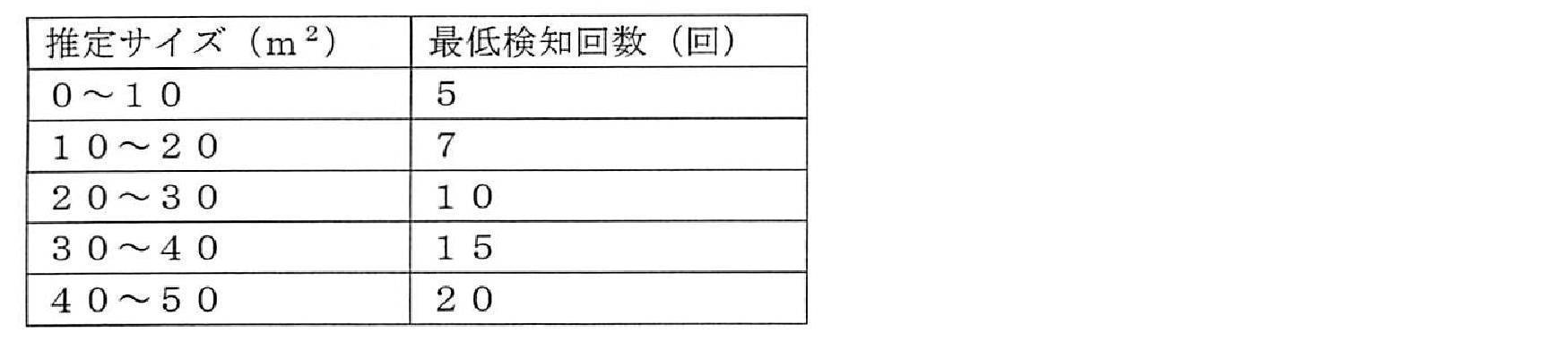
一方、図9(B)に示すように、掃除領域CA3内をランダムな経路RT32で自走する場合、掃除領域CA3の推定面積が約42(m2)とすると、最低検知回数は20回となる。
(i)この発明の自走式掃除機は、筐体と、前記筐体を走行させる走行部と、床面の掃除を行う清掃部と、前記筐体の周囲の障害物の位置を検知する障害検知部と、前記走行部、前記清掃部及び前記障害検知部を制御して前記筐体を自走させながら掃除を行わせる制御部とを備え、前記制御部は、前記障害検知部に周囲の障害物の位置を検知させ、前記障害物の位置に基づいて、掃除を行う走行時間を決定することを特徴とする。
また、障害物は、必ずしも実在する物体である必要はなく、例えば、バーチャルウォール信号から作られた電子的な障害物であってもよい。
(ii)この発明による自走式掃除機において、前記制御部は、前記障害物の位置に基づいて、前記筐体が自走し得る走行領域を決定するものであってもよい。
また、走行領域は、三角形状、正方形状、多角形状又はその他の形状であってもよい。走行領域が多角形状の場合、筐体が自走し得る走行領域は、筐体を取り囲む複数の障害物の位置を結ぶ線内に囲まれる多角形の領域である。
前述した実施形態の他にも、この発明について種々の変形例があり得る。それらの変形例は、この発明の範囲に属さないと解されるべきものではない。この発明には、請求の範囲と均等の意味及び前記範囲内でのすべての変形とが含まれるべきである。
Claims (5)
- 筐体と、前記筐体を走行させる走行部と、床面の掃除を行う清掃部と、前記筐体の周囲の障害物の位置を検知する障害検知部と、前記走行部、前記清掃部及び前記障害検知部を制御して前記筐体を自走させながら掃除を行わせる制御部とを備え、
前記制御部は、前記障害検知部に周囲の障害物の位置を検知させ、前記障害物の位置に基づいて、掃除を行う走行時間を決定することを特徴とする自走式掃除機。 - 前記制御部は、前記障害物の位置に基づいて、前記筐体が自走し得る走行領域を決定する請求項1に記載の自走式掃除機。
- 前記制御部は、前記走行領域内を自走中の前記筐体が前記走行領域外に出たとき、前記走行時間を修正する請求項2に記載の自走式掃除機。
- 前記制御部は、前記走行領域内を自走中の前記筐体が前記走行領域外に出たとき、前記走行領域外を前記筐体が走行した距離及び/又は時間に基づき前記走行領域及び前記走行時間を修正する請求項3に記載の自走式掃除機。
- 前記制御部は、前記走行領域内を自走中の前記筐体が前記走行領域外に出たとき、前記障害検知部に周囲の前記障害物の位置を検知させ、前記障害物の位置に基づき前記走行時間を修正する請求項3に記載の自走式掃除機。
Priority Applications (3)
| Application Number | Priority Date | Filing Date | Title |
|---|---|---|---|
| CN201480008634.XA CN105072966B (zh) | 2013-04-04 | 2014-02-14 | 自走式吸尘器 |
| US14/766,998 US20160000289A1 (en) | 2013-04-04 | 2014-02-14 | Self-propelled vacuum cleaner |
| KR1020157022343A KR20150107866A (ko) | 2013-04-04 | 2014-02-14 | 자주식 청소기 |
Applications Claiming Priority (2)
| Application Number | Priority Date | Filing Date | Title |
|---|---|---|---|
| JP2013-078845 | 2013-04-04 | ||
| JP2013078845A JP2014200449A (ja) | 2013-04-04 | 2013-04-04 | 自走式掃除機 |
Publications (1)
| Publication Number | Publication Date |
|---|---|
| WO2014162782A1 true WO2014162782A1 (ja) | 2014-10-09 |
Family
ID=51658086
Family Applications (1)
| Application Number | Title | Priority Date | Filing Date |
|---|---|---|---|
| PCT/JP2014/053490 Ceased WO2014162782A1 (ja) | 2013-04-04 | 2014-02-14 | 自走式掃除機 |
Country Status (5)
| Country | Link |
|---|---|
| US (1) | US20160000289A1 (ja) |
| JP (1) | JP2014200449A (ja) |
| KR (1) | KR20150107866A (ja) |
| CN (1) | CN105072966B (ja) |
| WO (1) | WO2014162782A1 (ja) |
Families Citing this family (29)
| Publication number | Priority date | Publication date | Assignee | Title |
|---|---|---|---|---|
| US8972052B2 (en) | 2004-07-07 | 2015-03-03 | Irobot Corporation | Celestial navigation system for an autonomous vehicle |
| US7706917B1 (en) * | 2004-07-07 | 2010-04-27 | Irobot Corporation | Celestial navigation system for an autonomous robot |
| US9233472B2 (en) | 2013-01-18 | 2016-01-12 | Irobot Corporation | Mobile robot providing environmental mapping for household environmental control |
| US9375847B2 (en) | 2013-01-18 | 2016-06-28 | Irobot Corporation | Environmental management systems including mobile robots and methods using same |
| WO2014113091A1 (en) | 2013-01-18 | 2014-07-24 | Irobot Corporation | Environmental management systems including mobile robots and methods using same |
| JP6621129B2 (ja) * | 2014-08-28 | 2019-12-18 | 東芝ライフスタイル株式会社 | 電気掃除機 |
| KR102339531B1 (ko) * | 2014-12-16 | 2021-12-16 | 에이비 엘렉트로룩스 | 로봇 청소 장치를 위한 경험-기반의 로드맵 |
| DE102015114883A1 (de) * | 2015-09-04 | 2017-03-09 | RobArt GmbH | Identifizierung und Lokalisierung einer Basisstation eines autonomen mobilen Roboters |
| CN105534408A (zh) * | 2016-01-27 | 2016-05-04 | 昆山硅步机器人技术有限公司 | 一种全自动机器人吸尘器 |
| JP6864433B2 (ja) * | 2016-01-29 | 2021-04-28 | 東芝ライフスタイル株式会社 | 電気掃除機 |
| CN107041718B (zh) * | 2016-02-05 | 2021-06-01 | 北京小米移动软件有限公司 | 清洁机器人及其控制方法 |
| TWI599994B (zh) * | 2016-03-15 | 2017-09-21 | Lumiplus Technology (Suzhou) Co Ltd | 即時監控載具系統 |
| CN106308685B (zh) * | 2016-08-23 | 2019-10-11 | 北京小米移动软件有限公司 | 清洁机器人及其控制方法 |
| JP6755751B2 (ja) * | 2016-08-26 | 2020-09-16 | シャープ株式会社 | 自動走行システム |
| JP6831210B2 (ja) * | 2016-11-02 | 2021-02-17 | 東芝ライフスタイル株式会社 | 電気掃除機 |
| JP6752118B2 (ja) * | 2016-11-09 | 2020-09-09 | 東芝ライフスタイル株式会社 | 自律走行体 |
| US11348269B1 (en) * | 2017-07-27 | 2022-05-31 | AI Incorporated | Method and apparatus for combining data to construct a floor plan |
| EP3731053B1 (en) * | 2018-02-28 | 2023-11-29 | Honda Motor Co., Ltd. | Management device, management system, moving body and program |
| CN108572647A (zh) * | 2018-07-24 | 2018-09-25 | 南京阿凡达机器人科技有限公司 | 一种基于移动机器人的智能家居管理方法和管理平台 |
| CN110926377B (zh) * | 2018-09-20 | 2022-08-26 | 苏州科瓴精密机械科技有限公司 | 机器人及其转动角度测量方法 |
| CN111198557B (zh) * | 2018-10-31 | 2022-03-18 | 苏州科瓴精密机械科技有限公司 | 行走机器人的控制方法及控制系统 |
| ES2964140T3 (es) * | 2019-01-31 | 2024-04-04 | Vorwerk Co Interholding | Electrodoméstico de funcionamiento con batería y estación de carga de batería |
| CN114174011B (zh) * | 2019-07-31 | 2024-04-19 | Lg电子株式会社 | 移动机器人 |
| US12364378B2 (en) | 2019-07-31 | 2025-07-22 | Lg Electronics Inc. | Moving robot and method of calculating moving distance of the same |
| JP7288416B2 (ja) | 2020-03-27 | 2023-06-07 | 本田技研工業株式会社 | 自律作業システム、自律作業設定方法、およびプログラム |
| ES2900546A1 (es) * | 2020-09-11 | 2022-03-17 | Cecotec Res And Development Sl | Método de filtrado de aire para robot de limpieza y/o desinfección |
| US12207787B2 (en) * | 2021-12-22 | 2025-01-28 | Kyndryl, Inc. | Debris signature-based robotic cleaning device navigation |
| US20240008704A1 (en) * | 2022-07-07 | 2024-01-11 | Irobot Corporation | Mobile cleaning robot with variable cleaning features |
| CN115487618B (zh) * | 2022-10-13 | 2024-06-07 | 沈阳建筑大学 | 一种针对粉尘处理的全自动机器人及其滤清结构 |
Citations (3)
| Publication number | Priority date | Publication date | Assignee | Title |
|---|---|---|---|---|
| JPH01106204A (ja) * | 1987-10-20 | 1989-04-24 | Sanyo Electric Co Ltd | 自走式掃除機 |
| JPH10105233A (ja) * | 1996-09-25 | 1998-04-24 | Minolta Co Ltd | 自律走行車 |
| JP2007330567A (ja) * | 2006-06-16 | 2007-12-27 | Hitachi Appliances Inc | 自走式掃除機 |
Family Cites Families (10)
| Publication number | Priority date | Publication date | Assignee | Title |
|---|---|---|---|---|
| US6142252A (en) * | 1996-07-11 | 2000-11-07 | Minolta Co., Ltd. | Autonomous vehicle that runs while recognizing work area configuration, and method of selecting route |
| US6496754B2 (en) * | 2000-11-17 | 2002-12-17 | Samsung Kwangju Electronics Co., Ltd. | Mobile robot and course adjusting method thereof |
| CN2664858Y (zh) * | 2003-06-05 | 2004-12-22 | 韦坤莲 | 一种机器人用接触式避障识别机构 |
| KR20050012049A (ko) * | 2003-07-24 | 2005-01-31 | 삼성광주전자 주식회사 | 공기 청정 기능을 구비한 로봇청소기 및 그 시스템 |
| KR100656701B1 (ko) * | 2004-10-27 | 2006-12-13 | 삼성광주전자 주식회사 | 로봇청소기 시스템 및 외부충전장치 복귀 방법 |
| KR100738888B1 (ko) * | 2005-10-27 | 2007-07-12 | 엘지전자 주식회사 | 로봇 청소기에 장착된 카메라의 제어 장치 및 방법 |
| ES2706729T3 (es) * | 2005-12-02 | 2019-04-01 | Irobot Corp | Sistema de robot |
| US20100114372A1 (en) * | 2008-10-30 | 2010-05-06 | Intellibot Robotics Llc | Method of cleaning a surface using an automatic cleaning device |
| CN101923351B (zh) * | 2009-06-12 | 2015-03-04 | 三星电子株式会社 | 机器人清洁器及其控制方法 |
| RU2012122469A (ru) * | 2009-11-06 | 2013-12-20 | Эволюшн Роботикс, Инк. | Способы и системы для полного охвата поверхности автономным роботом |
-
2013
- 2013-04-04 JP JP2013078845A patent/JP2014200449A/ja active Pending
-
2014
- 2014-02-14 WO PCT/JP2014/053490 patent/WO2014162782A1/ja not_active Ceased
- 2014-02-14 CN CN201480008634.XA patent/CN105072966B/zh not_active Expired - Fee Related
- 2014-02-14 KR KR1020157022343A patent/KR20150107866A/ko not_active Ceased
- 2014-02-14 US US14/766,998 patent/US20160000289A1/en not_active Abandoned
Patent Citations (3)
| Publication number | Priority date | Publication date | Assignee | Title |
|---|---|---|---|---|
| JPH01106204A (ja) * | 1987-10-20 | 1989-04-24 | Sanyo Electric Co Ltd | 自走式掃除機 |
| JPH10105233A (ja) * | 1996-09-25 | 1998-04-24 | Minolta Co Ltd | 自律走行車 |
| JP2007330567A (ja) * | 2006-06-16 | 2007-12-27 | Hitachi Appliances Inc | 自走式掃除機 |
Also Published As
| Publication number | Publication date |
|---|---|
| CN105072966A (zh) | 2015-11-18 |
| KR20150107866A (ko) | 2015-09-23 |
| CN105072966B (zh) | 2017-06-13 |
| JP2014200449A (ja) | 2014-10-27 |
| US20160000289A1 (en) | 2016-01-07 |
Similar Documents
| Publication | Publication Date | Title |
|---|---|---|
| WO2014162782A1 (ja) | 自走式掃除機 | |
| US9340116B2 (en) | Self-propelled electronic device | |
| KR102320204B1 (ko) | 로봇 청소기 및 이를 포함하는 로봇 청소기 시스템 | |
| CN104125792B (zh) | 吸尘器 | |
| JP2013169221A (ja) | 自走式掃除機 | |
| JP2013230294A (ja) | 自走式掃除機 | |
| WO2013121653A1 (ja) | 自走式電子機器 | |
| CN103857318B (zh) | 清扫机器人 | |
| JP6397974B2 (ja) | 自走式掃除機 | |
| JP2014180501A (ja) | 自走式掃除機 | |
| JP2014018562A (ja) | 自走式電子機器および自走式電子機器の充電台への帰還方法 | |
| JP2013169225A (ja) | 自走式掃除機 | |
| JP2013171314A (ja) | 自走式電子機器 | |
| JP2013169224A (ja) | 自走式掃除機 | |
| JP2013141341A (ja) | 自走式電子機器、電子機器の充電端子の清掃方法 | |
| JP2015156107A (ja) | 自走式電子機器 | |
| JP6106490B2 (ja) | 自走式電子機器および自走式電子機器の走行領域指定システム | |
| JP2014206895A (ja) | 自走式電子機器 | |
| JP2013250747A (ja) | 自走式電子機器 | |
| JP2014154011A (ja) | 自走式電子機器 | |
| CN104040265A (zh) | 自走式电子设备和自走式离子发生器 | |
| JP2013233230A (ja) | 自走式イオン放出装置 | |
| JP5986902B2 (ja) | 自走式掃除機 | |
| JP2013250748A (ja) | 自走式電子機器 | |
| JP2013231534A (ja) | 自走式電子機器、充電台及び自走式電子機器の除電システム |
Legal Events
| Date | Code | Title | Description |
|---|---|---|---|
| WWE | Wipo information: entry into national phase |
Ref document number: 201480008634.X Country of ref document: CN |
|
| 121 | Ep: the epo has been informed by wipo that ep was designated in this application |
Ref document number: 14780375 Country of ref document: EP Kind code of ref document: A1 |
|
| WWE | Wipo information: entry into national phase |
Ref document number: 14766998 Country of ref document: US |
|
| ENP | Entry into the national phase |
Ref document number: 20157022343 Country of ref document: KR Kind code of ref document: A |
|
| NENP | Non-entry into the national phase |
Ref country code: DE |
|
| 122 | Ep: pct application non-entry in european phase |
Ref document number: 14780375 Country of ref document: EP Kind code of ref document: A1 |