WO2014162759A1 - 冷蔵庫 - Google Patents
冷蔵庫 Download PDFInfo
- Publication number
- WO2014162759A1 WO2014162759A1 PCT/JP2014/051002 JP2014051002W WO2014162759A1 WO 2014162759 A1 WO2014162759 A1 WO 2014162759A1 JP 2014051002 W JP2014051002 W JP 2014051002W WO 2014162759 A1 WO2014162759 A1 WO 2014162759A1
- Authority
- WO
- WIPO (PCT)
- Prior art keywords
- refrigerator
- power saving
- target temperature
- displayed
- temperature setting
- Prior art date
Links
Images


Classifications
-
- F—MECHANICAL ENGINEERING; LIGHTING; HEATING; WEAPONS; BLASTING
- F25—REFRIGERATION OR COOLING; COMBINED HEATING AND REFRIGERATION SYSTEMS; HEAT PUMP SYSTEMS; MANUFACTURE OR STORAGE OF ICE; LIQUEFACTION SOLIDIFICATION OF GASES
- F25D—REFRIGERATORS; COLD ROOMS; ICE-BOXES; COOLING OR FREEZING APPARATUS NOT OTHERWISE PROVIDED FOR
- F25D29/00—Arrangement or mounting of control or safety devices
-
- G—PHYSICS
- G05—CONTROLLING; REGULATING
- G05B—CONTROL OR REGULATING SYSTEMS IN GENERAL; FUNCTIONAL ELEMENTS OF SUCH SYSTEMS; MONITORING OR TESTING ARRANGEMENTS FOR SUCH SYSTEMS OR ELEMENTS
- G05B15/00—Systems controlled by a computer
- G05B15/02—Systems controlled by a computer electric
-
- G—PHYSICS
- G06—COMPUTING; CALCULATING OR COUNTING
- G06T—IMAGE DATA PROCESSING OR GENERATION, IN GENERAL
- G06T11/00—2D [Two Dimensional] image generation
- G06T11/20—Drawing from basic elements, e.g. lines or circles
- G06T11/206—Drawing of charts or graphs
-
- F—MECHANICAL ENGINEERING; LIGHTING; HEATING; WEAPONS; BLASTING
- F25—REFRIGERATION OR COOLING; COMBINED HEATING AND REFRIGERATION SYSTEMS; HEAT PUMP SYSTEMS; MANUFACTURE OR STORAGE OF ICE; LIQUEFACTION SOLIDIFICATION OF GASES
- F25D—REFRIGERATORS; COLD ROOMS; ICE-BOXES; COOLING OR FREEZING APPARATUS NOT OTHERWISE PROVIDED FOR
- F25D2400/00—General features of, or devices for refrigerators, cold rooms, ice-boxes, or for cooling or freezing apparatus not covered by any other subclass
- F25D2400/36—Visual displays
Definitions
- the present invention relates to a refrigerator.
- the power saving level is determined based on the temperature of the “low”, “medium”, or “strong” storage room set by the user based on the type, amount, and storage period of the food. There was a refrigerator that displayed on the operation panel.
- the server receives and accumulates information about the usage status of the refrigerator transmitted from the information terminal device, and sends advice information to the information terminal device to save power by comparing current and past electricity charges,
- a refrigerator system in which an information terminal device displays the advice information on a display means to notify a user (for example, see Patent Document 1).
- JP 2002-147930 A page 3, page 4, FIGS. 1 and 2
- the power saving level is determined based on the temperature of the “low”, “medium”, or “strong” storage room set by the user, and the determination result is displayed on the operation panel. There is a problem that it is difficult for a person to know whether the set temperature of the storage room is suitable for his / her usage.
- the present invention has been made against the background of the above-described problems, and an object of the present invention is to obtain a refrigerator that performs power saving according to the use state of the user.
- the refrigerator of the present invention displays a storage room, a plurality of power saving levels indicating power saving indicators, operation display means for receiving an operation input for selecting one power saving level among the plurality of power saving levels, and the operation display means Control means for calculating one or a plurality of target temperature setting plans according to the selected one power saving level when an operation input for selecting one power saving level among the plurality of power saving levels displayed on
- the operation display means displays the target temperature setting plan calculated by the control means, and receives an operation input for executing the target temperature setting plan.
- the operation display means displays one or a plurality of target temperature setting plans corresponding to one power saving level selected by the user, and the operation display means performs an operation for executing the target temperature setting plan. Accept input. For this reason, the user can execute the target temperature setting plan after confirming whether or not the target temperature setting plan corresponding to the selected one power saving level is suitable for his / her own use situation. . Therefore, the refrigerator which performs power saving according to a user's use condition can be obtained.
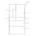
- FIG. 1 is a front view of a refrigerator 100 according to Embodiment 1 of the present invention.
- the refrigerator 100 includes a refrigerating room 1 provided at the uppermost stage as a storage room for storing food and the like, a switching room 2 and an ice making room 3 provided side by side on the lower side of the refrigerating room 1, a switching room 2 and It has a freezing room 4 provided on the ice making room 3 side and a vegetable room 5 provided on the lower side of the freezing room 4.
- each storage room is open, and the opening is provided with a door that closes the opening so as to be openable and closable.
- the refrigerating room 1 is provided with a double door opening / closing door, and the switching room 2, the ice making room 3, the freezing room 4, and the vegetable room 5 are provided with drawer doors.
- the switching chamber 2 is a storage below the refrigerating chamber 1 that can be switched from a freezing temperature zone ( ⁇ 18 ° C.) to a freezing temperature (3 ° C.), chilled (0 ° C.), soft freezing ( ⁇ 7 ° C.), etc. It is a room.
- a liquid crystal operation display panel 6 having a display function capable of adjusting the temperature and various settings of each storage compartment and displaying the temperature of each storage compartment is provided. Yes.
- a mechanical switch or a touch panel type can be adopted as an operation method of the operation display panel 6, for example, a mechanical switch or a touch panel type can be adopted.
- the operation display panel 6 may be installed inside the refrigerator 100, for example, on the side surface of the refrigerator compartment 1.
- the form of the refrigerator 100 is configured as described above, for example, the switching room 2 and the ice making room 3 are not provided, and the freezer room 4 and the vegetable room 5 are reversed in position. It is not limited to.
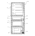
- FIG. 2 is a side sectional view of refrigerator 100 according to Embodiment 1 of the present invention.
- a compressor 92 on the back side of the refrigerator 100, a compressor 92, a cooler 93, and a blower fan 94 that blows cool air cooled by the cooler 93 to each storage chamber in the refrigerator 100 are provided.
- a cooler 93 is provided above the compressor 92, and a blower fan 94 is provided above the cooler 93.
- an air passage 95 is formed for introducing the cold air cooled by the cooler 93 into each storage chamber.
- each storage room is detected by a thermistor (not shown) installed in each storage room. Based on the temperature detected by the thermistor, the control means (not shown) has an opening degree of a damper (not shown) installed in the air passage 95 so that the temperature in each storage chamber becomes a preset temperature. The capacity of the compressor 92 and the amount of air blown by the blower fan 94 are controlled.
- Each storage room is provided with a door opening number detection sensor (not shown) for detecting the number of door opening times of the refrigerator 100.
- a storage case 2a capable of storing food is installed in the switching chamber 2.
- the freezer compartment 4 is provided with a storage case 4a for storing food.
- the vegetable compartment 5 is provided with an outer case 5a that can store food.
- the number of cases installed in each storage room may be one, but a plurality of cases may be provided according to the capacity of the entire refrigerator to improve the organization of the storage room.
- the cool air cooled by the cooler 93 passes through the air passage 95 and is sent to the refrigerator compartment 1, the switching compartment 2, the ice making compartment 3, and the freezer compartment 4 to cool each storage compartment.
- the return cold air in the refrigerator compartment 1 circulates in the vegetable compartment 5 through the return air passage (not shown) for the refrigerator compartment, and cools the vegetable compartment 5 inside. Then, the cold air circulated through the vegetable compartment 5 returns to the cooler 93 through the vegetable compartment return air passage (not shown).
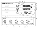
- FIG. 3 is a diagram showing an example of an operation main screen displayed on the operation display panel 6 of the refrigerator 100 according to Embodiment 1 of the present invention.
- the operation display panel 6 includes a pointer 10, a temperature setting evaluation column 11, a usage evaluation column 12, a comprehensive determination evaluation column 13, an evaluation display legend column 14, a power saving adjustment button 15, and a detail confirmation button. 16 is displayed.
- a symbol 11a indicating the result of calculating the power saving level based on the temperature information in each storage room (the set temperature set by the user) is displayed.
- a symbol 12a indicating a result of calculating a power saving level from information on the number of times of opening and closing the door is displayed.
- the comprehensive judgment evaluation column 13 displays a symbol 13a indicating a result calculated based on temperature information in each storage room and information on the number of times of opening and closing the door.
- the symbols 11a, 12a, and 13a are, for example, symbols imitating human facial expressions. Only one of the symbols 11a and 12a may be displayed.
- the evaluation display legend column 14 is a column for indicating the meaning of the symbols 11a, 12a, and 13a.
- symbols 14a, 14b, 14c, 14d, and 14e are displayed together with information related to power saving.
- the symbol 11a is the same symbol as the symbol 14d
- the symbol 12a is the same symbol as the symbol 14b
- the symbol 13a is the same symbol as the symbol 14c.
- the user can grasp the meaning of the symbols 11a, 12a, and 13a by referring to the symbols displayed in the evaluation display legend column 14, and intuitively understand how much power is currently being saved. Can do.
- the power saving adjustment button 15 is a button for switching to a screen for adjusting the power saving level, and is operated when the user wants to further save power with reference to the symbol 11a displayed in the temperature setting evaluation column 11, for example.
- the detail confirmation button 16 is a button for switching to a screen for confirming information based on the temperature adjustment setting and the number of times the refrigerator 100 is opened and closed.
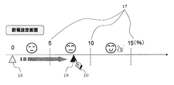
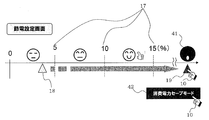
- FIG. 4 is a diagram showing an example of a power saving setting screen displayed on the operation display panel 6 of the refrigerator 100 according to Embodiment 1 of the present invention.
- FIG. 4 is a screen that transitions when the power saving adjustment button 15 is operated in FIG. As shown in FIG. 4, a pointer 10, a power consumption reduction guide amount 17, a power saving status cursor 18, and a power saving target value 19 are displayed on the operation display panel 6.
- the power consumption reduction target amount 17 is displayed in increments of 5% from “0%” to “15%”, for example, and “0%”, “5%”, “10%”, and “15%” are indicated. Yes.
- the power saving state cursor 18 is a cursor that can be slid left and right by the user using the pointer 10, and can be slid to a position such as a power saving target value 19 to adjust the power saving level. In the state transitioned to FIG. 4, the power saving status cursor 18 is at a position indicating the current power saving level.
- the power saving level represents a power saving index that can be switched continuously or stepwise, and is used to calculate a power saving plan to be described later.
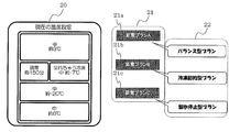
- FIG. 5 is a diagram showing an example of a power saving plan selection screen displayed on the operation display panel 6 of the refrigerator 100 according to Embodiment 1 of the present invention.
- FIG. 5 is a screen displayed when the power saving target value 19 is set by operating the power saving situation cursor 18 in FIG.
- the operation display panel 6 displays a current temperature display area 20, a power saving plan display area 21, and a simple explanation display area 22.
- the current temperature display area 20 is an area where, for example, a diagram schematically showing a front view of the refrigerator 100 is displayed, and a word indicating information in the storage room is displayed on the design of each storage room. Yes. For example, this term is “medium about 3 ° C.” for the refrigerator room 1, “about -7 ° C. during freezing that is broken” for the switching room 2, “about 150 minutes” for the ice making room 3, and “medium about ⁇ for the freezer room 4” “20 ° C.” for the vegetable room 5, “about 6 ° C.”. “Medium” indicates the temperature of the storage room, “normal” indicates the ice making speed, “about 150 minutes” indicates the time required for ice making, and the ice making time indicates the amount of cold air supplied to the ice making room. It is determined by adjusting.
- the power saving plan display area 21 is an area where the power saving plan setting buttons 21a, 21b, and 21c are displayed.
- the power saving plan setting button 21a corresponds to “power saving plan A”
- the power saving plan setting button 21b corresponds to “power saving plan B”
- the power saving plan setting button 21c corresponds to “power saving plan C”.
- These power saving plans are plans that define the target temperature of each storage room calculated according to the selected power saving level.
- the control means (not shown) calculates one or a plurality of power saving plans for achieving the power saving target value 19 according to the power saving target value 19 set by the user.
- the power saving plan displayed on the operation display panel 6 is not limited to three as described above, and may be one or two, or may be four or more.
- the power saving plan of Embodiment 1 corresponds to the target temperature setting plan of the present invention.
- the simple explanation display area 22 is an area for displaying a word explaining the power saving plan setting buttons 21a, 21b, and 21c.
- the words are, for example, “balance type plan”, “refrigeration saving type plan”, and “ice making stop type plan”. It is.
- the “balanced plan” is an explanation of “power saving plan A”
- the “refrigeration saving plan” is an explanation of “power saving plan B”
- the “ice-making stop type plan” is an explanation of “power saving plan C”. As you can see, they are displayed in association with each power-saving plan.
- FIG. 6 is a diagram showing an example of a detailed power saving plan temperature explanatory diagram displayed on the operation display panel 6 of the refrigerator 100 according to Embodiment 1 of the present invention.
- FIG. 6 is a screen displayed when the power saving plan setting button 21a is selected in FIG.
- the operation display panel 6 displays a current temperature display area 20, a set temperature display area 23, a caution button 24, an enter button 25, and a cancel button 26.
- the set temperature display area 23 is an area where a diagram schematically showing a front view of the refrigerator 100 is shown.
- the design of each storage room shows the state of each storage room. The wording shown is displayed.
- information such as the set temperature of each storage room when the user executes “power saving plan A” is shown. Specifically, for example, “slightly weaker about 5 ° C.” for the refrigerator room 1, “about -7 ° C. during freezing during cutting” for the switching room 2, “normally about 170 minutes” for the ice making room 3, Slightly weak (about -18 ° C), vegetable room 5 is "medium about 6 ° C".
- the caution button 24 is a button for displaying a caution when the temperature in the storage chamber of the refrigerator 100 changes.
- the attention button 24 When the attention button 24 is operated, for example, information indicating that the storage period of the food is shortened and the time for generating ice is lengthened is displayed on the operation display panel 6.
- the determination button 25 displays a word indicating affirmation such as “Yes”.
- the cancel button 26 displays a word indicating negative such as “No (see another plan)”. The functions of the decision button 25 and the cancel button 26 will be described later.
- the OK button 25 To operate.
- the compressor 92 and the damper (not shown) are controlled so that the temperature in each storage room becomes a set temperature defined in the power saving plan selected by the user, and the cooling operation is performed. Is executed.
- the user uses his / her own usage in consideration of the in-chamber information such as the temperature displayed in the set temperature display area 23 and the caution points of the power saving plan displayed by operating the caution button 24. If it is determined that it does not match, the cancel button 26 is operated. When the cancel button 26 is operated, the screen returns to the screen of FIG. 5 and the user can confirm another power saving plan again.
- the user can confirm the power saving plan that suits him / herself through the operation display panel 6, so that he / she can easily adjust the temperature and save power after understanding that it is suitable for his / her use situation. Can do.
- FIG. 7 is a diagram showing an example of usage evaluation details displayed on the operation display panel 6 of the refrigerator 100 according to Embodiment 1 of the present invention.
- FIG. 7 is a screen that transitions when the detail confirmation button 16 is operated in FIG.
- the operation display panel 6 displays a pointer 10, a comprehensive determination level transition graph 27, a door opening status display area 28, and a usage advice display area 29.
- the comprehensive judgment level transition graph 27 is a graph showing the transition of the result of the power saving degree calculated based on the information temperature (set temperature set by the user) in each storage room and the number of times of opening and closing the door.
- the horizontal axis indicates the time from 72 hours before.
- the power saving level is shown, for example, in four stages “0” to “3”.
- the door open status display area 28 is an area in which a diagram schematically showing the front view of the refrigerator 100 is displayed. A word indicating the open status is displayed. For example, one of “Large”, “Normal”, and “Less” is displayed in order of the number of times the door is opened. For example, “more” for the refrigerator compartment 1, “less” for the switching chamber 2, “normal” for the ice making chamber 3, “more” for the freezer compartment 4, and “normal” for the vegetable compartment 5.
- the mark 28a is attached
- the mark 28a is a mark attached to the design of the storage room having a long door opening time (for example, the door is open for 1 minute or longer).
- the usage advice display area 29 is an area where the words 29a and 29b and the history confirmation button 30 are displayed.
- the wording 29a is a wording indicating the meaning of the mark 28a and that the mark 28a remains in the history, for example, “the door is open for a long time (opening for 1 minute or longer) ⁇ the history remains”.
- the wording 29b is, for example, a wording that prompts the user to shorten the door opening time. For example, “* opening and closing the door as quickly as possible”.
- the history confirmation button 30 is a button for making a transition to a screen that displays details of the number of times the door is opened. In the history confirmation button 30, for example, a word “view details” is displayed.
- FIG. 8 is a diagram showing an example of the door opening frequency display graph 31 displayed on the operation display panel 6 of the refrigerator 100 according to Embodiment 1 of the present invention.
- FIG. 8 is a screen that transitions when the history confirmation button 30 in FIG. 7 is operated.
- the door opening number display graph 31 shows the number of door opening times of the refrigerator compartment 1, the switching room 2, the ice making room 3, the freezing room 4, and the vegetable room 5 for each hour.
- the horizontal axis indicates the time zone from 24 hours ago until now.
- the vertical axis shows the number of times the door is opened from 0 to 30 times.
- FIG. 8 When the user moves the pointer 10 so as to be positioned within the coordinate area where the mark 28a is displayed, the number of times for each storage room where the door opening time is equal to or longer than the predetermined time is displayed on the operation display panel 6. .
- a display example for example, as shown in FIG. 8, “twice refrigerator compartment” and “twice freezer compartment”. Thereby, it turns out that the door of the refrigerator compartment 1 was opened twice or more for predetermined time, and the door of the freezer compartment 4 was opened twice or more for predetermined time.
- the refrigerator 100 displays a plurality of power saving levels indicating power saving indicators, and an operation display unit that receives an operation input for selecting one power saving level among the plurality of power saving levels.
- a control means for calculating one or a plurality of power saving plans according to the selected power saving level when an operation input for selecting one power saving level among the plurality of power saving levels displayed on the operation display means is provided;
- the operation display means displays the power saving plan calculated by the control means and accepts an operation input for executing the power saving plan. For this reason, the user can execute the target temperature setting plan after confirming whether or not the target temperature setting plan corresponding to the selected one power saving level is suitable for his / her own use situation. . Therefore, the refrigerator which performs power saving according to a user's use condition can be obtained.
- the refrigerator 100 displays the in-chamber information such as the current temperature in the operation temperature display area 20 on the operation display panel 6, and the temperature when the selected power saving plan is executed. Is displayed in the display area 23 of the set temperature, etc., and the number of times the door is opened in the refrigerator compartment 1, the switching compartment 2, the ice making compartment 3, the freezer compartment 4, and the vegetable compartment 5 is displayed every hour. A graph 31 is displayed. For this reason, the user can visually recognize the current operation state of the refrigerator 100 and the operation state of the refrigerator 100 after power saving, grasp the power saving state and the power saving method, and can save power without difficulty. It becomes.
- FIG. FIG. 9 is a diagram illustrating an example in which a home network is constructed by connecting the refrigerator 100 according to Embodiment 2 of the present invention and an external device, for example, a home appliance, to the centralized controller 132.
- an external device for example, a home appliance
- a refrigerator 100 inside the house 200, there are a refrigerator 100, a centralized controller 132, an air conditioner 134, a television 135, a tablet terminal 136 that is an external interface device including a display unit and an operation unit, A switchboard 137 provided with a power sensor is provided.
- a solar panel 139 and an electric vehicle 140 are provided outside the house 200.
- the centralized controller 132 is connected to the refrigerator 100 and external devices such as the air conditioner 134, the television 135, the tablet terminal 136, and the switchboard 137, and a home network is constructed.
- the switchboard 137 is connected not only to the centralized controller 132 but also to the solar panel 139 and the storage battery of the electric vehicle 140.
- the centralized controller 132 is an external data storage server, and is connected to the Internet cloud 300 that stores data transmitted through the network, so that the centralized controller 132 and the Internet cloud 300 can exchange information. .
- the refrigerator 100 includes a communication unit configured by an arbitrary network interface such as a LAN interface.
- the communication means of the refrigerator 100 is configured to be connected to the above-described external device.
- This communication means corresponds to the external device communication means, cloud communication means, and interface device communication means of the present invention.
- the refrigerator 100 is connected to external devices such as the centralized controller 132, the air conditioner 134, the television 135, the tablet terminal 136, the switchboard 137, and the Internet cloud 300 through this communication unit.
- the centralized controller 132 is connected to the switchboard 137 provided with a power sensor. For this reason, the centralized controller 132 can grasp the power consumption of the entire house 200 and each external device, and when the power consumption of a certain external device increases, the power consumption such as suppressing the power consumption of other external devices. You can control.
- the centralized controller 132 is connected to the tablet terminal 136.
- a tablet terminal 136 having a touch panel as an operation unit and a liquid crystal screen as a display unit is equipped with remote control software for remotely controlling the refrigerator 100 and other external devices.
- the user can remotely operate each external device by operating the tablet terminal 136 instead of the refrigerator 100 or the operation panel or remote control of each external device.
- the tablet terminal 136 acquires the operation information (arbitrary information such as the ON / OFF state and the set temperature) transmitted from the refrigerator 100 and other external devices, and displays the operation information. To do. For this reason, the user can confirm remotely the state of the refrigerator 100 or an external apparatus.
- the centralized controller 132 is connected to the Internet cloud 300, which is an external data storage server, via the Internet, and the centralized controller 132 and the internet cloud 300 can exchange information. For this reason, the centralized controller 132 can accumulate
- the switchboard 137 is not only connected to the centralized controller 132 but also connected to the solar panel 139 and the storage battery of the electric vehicle 140. For this reason, when it is difficult for the power company to supply power, power can be supplied from the storage battery of the solar panel 139 and the electric vehicle 140 to the switchboard 137, and power can be distributed to the refrigerator 100 and each external device.
- FIG. 9 an operation example for notifying the refrigerator 100 that power supply is difficult when power supply is difficult due to an emergency earthquake warning will be described.
- the internet cloud 300 transmits information indicating that it is difficult to supply power, such as an earthquake early warning, to the centralized controller 132 when power supply is difficult.
- the centralized controller 132 transmits information indicating that it is difficult to supply power to the refrigerator 100 and each external device.
- FIG. 10 is displayed on the operation display panel 6.
- FIG. 10 is a diagram showing an example of a power saving setting screen in the power consumption save mode displayed on the operation display panel 6 of the refrigerator 100 according to the second embodiment of the present invention.
- the operation display panel 6 displays a pointer 10, a power consumption reduction target amount 17, a power saving status cursor 18, a power saving target value 19, and a power consumption save mode icon 41, as shown in FIG.
- a power saving level higher than the power saving level to be selected can be selected.
- the power consumption save mode icon 42 is not displayed on the operation display panel 6 in the state transitioned to FIG.
- the power consumption save mode icon 41 is, for example, a pattern that imitates the facial expression of a person, and is for informing the user that it is difficult to supply power.
- the operation example of FIG. 10 will be described.
- the power consumption save mode icon 42 is displayed. Is displayed on the operation display panel 6.
- the screen transitions to the screen in FIG.
- the operation display panel 6 may be configured to display the screen of FIG. 11 without displaying FIG. 10 when receiving information indicating that the refrigerator 100 has difficulty in supplying power.
- the “power consumption save mode” is a mode that retains a function capable of maintaining a living with the minimum power consumption, and is a mode that can be set only when power supply is difficult.
- this mode is set, the temperature of each storage room is reduced by, for example, about 30% or more of power consumption compared to normal operation (for example, operation at a power saving level of 0%) The power consumption is set to be the lowest.
- FIG. 11 is a diagram showing an example of a power consumption save mode temperature detailed explanatory diagram in the power consumption save mode displayed on the operation display panel 6 of the refrigerator 100 according to Embodiment 2 of the present invention.
- FIG. 11 is a screen that transitions when the power consumption save mode icon 42 is operated in FIG.
- the operation display panel 6 includes a refrigerator current temperature display area 20, a set temperature display area 43 set in the power consumption save mode, a caution button 44, a decision button 45, and A cancel button 46 is displayed.
- the set temperature display area 43 is a diagram schematically showing, for example, a front view of the refrigerator 100, and each storage room displays a word indicating the state of each storage room.
- the period during which it is difficult to supply power is assumed to be, for example, about two weeks, so the set temperature of the freezer room 4 is about two weeks during the food storage period ⁇ It is set to 7 ° C.
- the temperature of the refrigerator compartment 1 and the vegetable compartment 5 is 15 degreeC or more, all can be utilized as a cool dark place.
- the temperature of the switching chamber 2 and the ice making chamber 3 is about 0 degreeC, both can be utilized as a chilled chamber.
- the value of the temperature of each storeroom is an example, and the value of another temperature may be sufficient.
- the caution button 44 is a button for displaying cautions on how to use each storage room in the power saving mode.
- the attention point button 44 When the attention point button 44 is operated, for example, the contents such as what kind of ingredients can be stored in each storage room and how long are displayed. More specifically, for example, as a method of using the freezer room 4, the food storage period in the normal freezing is about 2 months, but the food storage period in the power saving mode is about 2 weeks. It is a content that informs the period.
- the determination button 45 displays a word indicating affirmation such as “Yes”.
- the cancel button 46 displays a negative word such as “No”. The user can easily understand the demerits caused by changes in the operation of the refrigerator by operating the caution button 44.
- the determination button 45 When the user confirms the display area 43 such as the set temperature of each storage room of the refrigerator 100 and determines that the power consumption saving mode is to be executed, the determination button 45 is operated. When the determination button 45 is operated, the power consumption saving mode is executed. On the other hand, the user considers the in-chamber information such as the temperature displayed in the set temperature display area 43, the cautions in the power consumption save mode displayed by operating the caution button 24, and the demerits due to operation changes. If it is determined not to execute the power consumption save mode, the cancel button 46 is operated. When the cancel button 46 is operated, the screen returns to the screen of FIG. In addition, although the example which changes to FIG. 11 when the power consumption save mode icon 42 of FIG.
- the refrigerator 100 and each external device when it is difficult to supply power, power is not supplied to the refrigerator 100 and each external device from devices other than the solar panel 139 and the storage battery of the electric vehicle 140. For this reason, the total amount of power supplied to the refrigerator 100 and each external device when power supply is difficult is larger than the total amount of power supplied to the refrigerator 100 and each external device when power supply is not difficult, It is assumed that it will decrease.
- the refrigerator 100 and each external device when the refrigerator 100 and each external device are provided with a communication unit with the central controller 132 and information indicating that power supply is difficult is acquired from the central controller, the refrigerator 100 and each external device Was operated with minimum power consumption. For this reason, the function which can maintain a life can be maintained.
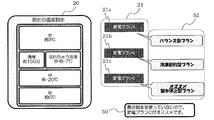
- FIG. 12 is a diagram showing an example of a power saving plan selection screen displayed on the operation display panel 6 of the refrigerator 100 according to Embodiment 3 of the present invention.
- FIG. 12 is a screen that transitions in FIG. 4 when the power saving target value 19 is set by operating the power saving situation cursor 18.
- the operation display panel 6 displays a current temperature display area 20, a power saving plan display area 21, a wording 50, and a simple explanation display area 52.
- the description of the parts common to the first and second embodiments is omitted, and the difference from the first and second embodiments will be mainly described.
- each storage room of the refrigerator 100 is equipped with a load detection sensor (not shown) or a storage camera (not shown) that can determine the food load.
- the sensor which judges food load amount does not specifically limit a detection method, For example, a mechanical sensor and an optical sensor are employable.
- the control means determines the power saving level set by the user and the food load amount of the refrigerator 100 using the detection information of the load detection sensor or the internal camera, and the operation display panel 6 matches the user.
- the recommended power saving plan is displayed.
- the load detection sensor or the internal camera is equivalent to the load detection means of the present invention.
- the characters “recommended ice making stop type plan” in the brief explanation display area 52 are displayed in association with the power saving plan setting button 21c, and the user selects “power saving plan C” and “power saving plan”. It can be understood that it is recommended over “A” and “Power Saving Plan B”.
- the wording 50 is, for example, a wording indicating the reason why the above-mentioned “power saving plan C” is recommended. Specifically, for example, “I have not used ice making recently, so I recommend Power Saving Plan C”.
- the user can grasp the recommended power saving plan from the plurality of power saving plans together with the reason for the recommendation, so that the user understands that it is suitable for his / her own usage. Temperature adjustment and power saving can be implemented, and there is no need to worry about which power saving plan to save power.
- a recommended power-saving plan is other power-saving plans.
- the recommended power saving plan may be distinguished from other power saving plans. Further, only a recommended plan may be displayed on the operation display panel 6. That is, only the power saving plan C may be displayed on the operation display panel 6.
- FIG. 13 is a diagram illustrating an example of a detailed power saving plan temperature explanatory diagram displayed on the operation display panel 6 of the refrigerator 100 according to Embodiment 4 of the present invention.
- FIG. 13 is an example of a screen that transitions when “power saving plan A” of the power saving plan setting button 21a in FIG. 5 is selected.
- the description of the parts common to the first to third embodiments will be omitted, and the difference from the first to third embodiments will be mainly described.
- a current temperature display area 20, a set temperature display area 23, a caution point button 24, a decision button 25, and a cancel button 26 are displayed as in FIG.
- the current power consumption 58 is written below the current temperature display area 20, and the power consumption plan consumption is displayed below the set temperature display area 23.
- the amount of power 59 is also shown.
- the current power consumption 58 is “current power consumption 0.924 kwh / d”, and the power consumption 59 in the power saving plan is “expected power consumption 0.814 kwh / d of this plan”.
- the current power consumption 58 as described above and the power consumption 59 during the power saving plan are determined by the control unit based on detection information of a power consumption detection sensor (not shown) that detects the power consumption of the refrigerator 100, for example. Calculated.
- the user can quantitatively grasp the power consumption amount, leading to improvement of the user's willingness to save power. .
- the power consumption is not displayed on the operation display panel 6 at the current and post-power-saving temperature, but is calculated from the display of the current power consumption and the relative value of the power-saving plan, or from the power consumption. You can display the electricity price per day.
- Embodiment 5 FIG.
- the description of the parts common to the first to fourth embodiments will be omitted, and the description will focus on the differences from the first to fourth embodiments.
- a network as shown in FIG. 9 is constructed as in the second embodiment.
- external devices such as an air conditioner 134 and a television 135 have a power consumption detection sensor (not shown). When the power consumption detected by the power consumption detection sensor increases by more than the threshold, the external device transmits information indicating that the power consumption is greater than or equal to the threshold power from the centralized controller 132 to the refrigerator 100.
- the refrigerator 100 acquires information indicating that the power consumption of the external device is equal to or greater than the threshold power consumption via the centralized controller 132, the power consumption is higher than the current power consumption preset in the refrigerator 100. A power saving plan with a small amount is executed, and the temperature in the storage room changes. In this way, by suppressing the power consumption of the refrigerator 100, it becomes possible to cut the peak of the power consumption of the entire home, and it is possible to suppress excessive power consumption in the entire home.
- the refrigerator 100 may be directly connected to another external device.
- information indicating that the power consumption detected by the power consumption detection sensor is equal to or greater than the threshold power is transmitted to the refrigerator 100 from another external device.
- the method of reducing the power consumption is not limited to the above example, and when the power consumption of the external device other than the refrigerator 100 is increased as described above, the control means operates the refrigerator 100. Among them, the start of the defrosting heater with a relatively large amount of power consumption may be delayed to perform peak cut.
- Embodiment 6 FIG. Next, the sixth embodiment will be described.
- the description of the parts common to the first to fifth embodiments will be omitted, and the difference from the first to fifth embodiments will be mainly described.
- the network as shown in FIG. 9 is constructed, and the refrigerator 100 can exchange information with the Internet cloud 300 via the centralized controller 132. Yes.
- the data transmission / reception in the sixth embodiment will be described below.
- the refrigerator 100 transmits operation information such as power consumption, information indicating the load, information indicating the number of times the door is opened to the Internet cloud 300 via the centralized controller 132
- the Internet cloud 300 is connected to the refrigerator 100.
- the operation information may be configured to be transmitted from the refrigerator 100 to the Internet cloud 300 every time the operation information is updated inside the refrigerator 100, or may be transmitted from the refrigerator 100 to the Internet cloud 300 at regular intervals. You may comprise.
- the operation information of the refrigerator 100 accumulated on the Internet cloud 300 can be extracted by a device (such as a personal computer or a refrigerator) connected to the Internet. Further, the configuration in which the refrigerator 100 can exchange information with the Internet cloud 300 via the centralized controller 132 has been described. However, the refrigerator 100 is configured to be directly connected to the Internet cloud 300 without using the centralized controller 132. May be.
- At least one of the operation display panel 6 and the tablet terminal 136 corresponds to the “operation display means” of the present invention.
Priority Applications (4)
| Application Number | Priority Date | Filing Date | Title |
|---|---|---|---|
| SG11201507695VA SG11201507695VA (en) | 2013-04-03 | 2014-01-20 | Refrigerator |
| US14/776,845 US20160018158A1 (en) | 2013-04-03 | 2014-01-20 | Refrigerator |
| CN201480017594.5A CN105102911B (zh) | 2013-04-03 | 2014-01-20 | 冰箱 |
| EP14779879.7A EP2982916A4 (de) | 2013-04-03 | 2014-01-20 | Kühlschrank |
Applications Claiming Priority (2)
| Application Number | Priority Date | Filing Date | Title |
|---|---|---|---|
| JP2013-077882 | 2013-04-03 | ||
| JP2013077882A JP6080655B2 (ja) | 2013-04-03 | 2013-04-03 | 冷蔵庫 |
Publications (1)
| Publication Number | Publication Date |
|---|---|
| WO2014162759A1 true WO2014162759A1 (ja) | 2014-10-09 |
Family
ID=51658065
Family Applications (1)
| Application Number | Title | Priority Date | Filing Date |
|---|---|---|---|
| PCT/JP2014/051002 WO2014162759A1 (ja) | 2013-04-03 | 2014-01-20 | 冷蔵庫 |
Country Status (6)
| Country | Link |
|---|---|
| US (1) | US20160018158A1 (de) |
| EP (1) | EP2982916A4 (de) |
| JP (1) | JP6080655B2 (de) |
| CN (1) | CN105102911B (de) |
| SG (1) | SG11201507695VA (de) |
| WO (1) | WO2014162759A1 (de) |
Cited By (2)
| Publication number | Priority date | Publication date | Assignee | Title |
|---|---|---|---|---|
| JP2016080232A (ja) * | 2014-10-15 | 2016-05-16 | 三菱電機株式会社 | 冷蔵庫及びそれを備えたネットワークシステム |
| JP7387694B2 (ja) | 2021-11-16 | 2023-11-28 | 東芝ライフスタイル株式会社 | プログラムおよび冷蔵庫 |
Families Citing this family (7)
| Publication number | Priority date | Publication date | Assignee | Title |
|---|---|---|---|---|
| JP6563255B2 (ja) * | 2015-06-10 | 2019-08-21 | シャープ株式会社 | 冷蔵庫 |
| US11016634B2 (en) * | 2016-09-01 | 2021-05-25 | Samsung Electronics Co., Ltd. | Refrigerator storage system having a display |
| JP7016000B2 (ja) * | 2016-12-21 | 2022-02-04 | パナソニックIpマネジメント株式会社 | 冷蔵庫 |
| CN107894717A (zh) * | 2017-09-30 | 2018-04-10 | 珠海格力电器股份有限公司 | 一种设备控制方法、装置、存储介质及终端 |
| JP7101130B2 (ja) * | 2019-01-22 | 2022-07-14 | 日立グローバルライフソリューションズ株式会社 | 冷蔵庫用遠隔制御装置、冷蔵庫用遠隔制御装置の制御方法およびプログラム |
| CN112179035B (zh) * | 2019-07-05 | 2022-05-20 | 青岛海尔电冰箱有限公司 | 冰箱管理方法和装置 |
| US11936489B2 (en) | 2021-02-02 | 2024-03-19 | True Manufacturing Co., Inc. | Systems, methods, and appliances that enable regional control of refrigeration appliances |
Citations (14)
| Publication number | Priority date | Publication date | Assignee | Title |
|---|---|---|---|---|
| JPH06213548A (ja) * | 1993-01-18 | 1994-08-02 | Hitachi Ltd | 冷蔵庫 |
| JPH06288595A (ja) * | 1992-05-08 | 1994-10-11 | Matsushita Electric Ind Co Ltd | 空気調和機の室内温度設定装置 |
| JPH08261624A (ja) * | 1995-03-24 | 1996-10-11 | Matsushita Refrig Co Ltd | 冷凍冷蔵庫の制御装置 |
| JPH08279076A (ja) * | 1995-04-07 | 1996-10-22 | Mitsubishi Electric Corp | 自動販売機とその制御方法 |
| JP2002147930A (ja) | 2000-11-06 | 2002-05-22 | Matsushita Refrig Co Ltd | 冷蔵庫 |
| JP2004265341A (ja) * | 2003-03-04 | 2004-09-24 | Fuji Electric Retail Systems Co Ltd | 設備機器監視システム |
| JP2004325027A (ja) * | 2003-04-28 | 2004-11-18 | Toshiba Corp | 店舗管理システム |
| JP2005249358A (ja) | 2004-03-08 | 2005-09-15 | Matsushita Electric Ind Co Ltd | 冷蔵庫システムおよびそのプログラム |
| JP2007064610A (ja) * | 2005-08-30 | 2007-03-15 | Key Stream Kk | 冷却装置の温度管理制御システム |
| JP2012220186A (ja) * | 2011-04-12 | 2012-11-12 | Lg Electronics Inc | ディスプレイ装置及びこれを備える冷蔵庫 |
| JP2013002717A (ja) * | 2011-06-15 | 2013-01-07 | Fujitsu General Ltd | 空気調和機 |
| WO2013008934A1 (ja) * | 2011-07-13 | 2013-01-17 | 日東電工株式会社 | オンデマンド型電力制御システム、オンデマンド型電力制御システムプログラム及びそのプログラムを記録したコンピュータ読み取り可能な記録媒体 |
| JP2013036699A (ja) * | 2011-08-09 | 2013-02-21 | Sharp Corp | 冷却庫 |
| JP2013044462A (ja) * | 2011-08-23 | 2013-03-04 | Mitsubishi Electric Corp | 空調システム制御装置 |
Family Cites Families (37)
| Publication number | Priority date | Publication date | Assignee | Title |
|---|---|---|---|---|
| US3974660A (en) * | 1974-07-01 | 1976-08-17 | Tecumseh Products Company | Power supply for refrigeration units |
| US4938027A (en) * | 1989-11-06 | 1990-07-03 | Amana Refrigeration, Inc. | Apparatus and method for defrosting refrigerator in vacation mode |
| US4966004A (en) * | 1989-11-06 | 1990-10-30 | Amana Refrigeration, Inc. | Electronic control mounting apparatus for refrigerator |
| KR960001985B1 (ko) * | 1991-06-07 | 1996-02-08 | 삼성전자주식회사 | 냉장고의 자동운전제어방법 |
| US5355686A (en) * | 1993-08-11 | 1994-10-18 | Micro Weiss Electronics, Inc. | Dual temperature control of refrigerator-freezer |
| KR100499028B1 (ko) * | 1998-09-16 | 2005-09-02 | 삼성전자주식회사 | 냉장고의 운전 제어방법 |
| JP2001045403A (ja) * | 1999-08-04 | 2001-02-16 | Sanyo Electric Co Ltd | 映像処理装置 |
| JP3800900B2 (ja) * | 1999-09-09 | 2006-07-26 | 三菱電機株式会社 | 冷凍冷蔵庫、冷凍冷蔵庫の運転方法 |
| JP4560947B2 (ja) * | 2000-11-06 | 2010-10-13 | パナソニック株式会社 | 情報発信装置及び情報発信装置を備えた貯蔵庫 |
| US6802186B2 (en) * | 2001-01-05 | 2004-10-12 | General Electric Company | Refrigerator system and software architecture |
| US6732319B2 (en) * | 2001-01-05 | 2004-05-04 | General Electric Company | Method and apparatus for protecting appliance memory contents |
| US6397612B1 (en) * | 2001-02-06 | 2002-06-04 | Energy Control Equipment | Energy saving device for walk-in refrigerators and freezers |
| CN1239871C (zh) * | 2001-05-16 | 2006-02-01 | 广东科龙电器股份有限公司 | 一种分时运行冰箱及其运行方法 |
| KR100474329B1 (ko) * | 2002-05-07 | 2005-03-08 | 엘지전자 주식회사 | 냉장고의 압축기 운전제어방법 |
| GB2439490B (en) * | 2005-03-08 | 2008-12-17 | Radio Usa Inc E | Systems and methods for modifying power usage |
| JP2007010208A (ja) * | 2005-06-29 | 2007-01-18 | Toshiba Corp | 冷蔵庫 |
| US7634918B2 (en) * | 2005-07-07 | 2009-12-22 | Sanyo E & E Corporation | Refrigerator having user-controlled functions |
| WO2008129718A1 (ja) * | 2007-04-17 | 2008-10-30 | Mitsubishi Electric Corporation | 冷蔵庫および冷凍保存方法 |
| JP2011161774A (ja) * | 2010-02-09 | 2011-08-25 | Seiko Epson Corp | 印刷装置および印刷装置の制御方法 |
| US9104211B2 (en) * | 2010-11-19 | 2015-08-11 | Google Inc. | Temperature controller with model-based time to target calculation and display |
| KR101813030B1 (ko) * | 2010-12-29 | 2017-12-28 | 엘지전자 주식회사 | 냉장고 |
| KR101774054B1 (ko) * | 2011-04-15 | 2017-09-12 | 엘지전자 주식회사 | 네트워크 시스템 및 그 제어방법 |
| KR20130009055A (ko) * | 2011-07-14 | 2013-01-23 | 엘지전자 주식회사 | 냉장고 |
| KR20130014080A (ko) * | 2011-07-29 | 2013-02-07 | 삼성전자주식회사 | 냉장고 및 그 제어 방법 |
| US20130191243A1 (en) * | 2012-01-06 | 2013-07-25 | Lg Electronics Inc. | Terminal and a control method thereof |
| EP2827084A4 (de) * | 2012-03-13 | 2015-09-02 | Panasonic Corp | Kühlschrank und informationssystem |
| JP5790620B2 (ja) * | 2012-10-30 | 2015-10-07 | 三菱電機株式会社 | 冷蔵庫システム |
| KR20140061619A (ko) * | 2012-11-13 | 2014-05-22 | 한국전자통신연구원 | 가정용 에너지 관리 장치 및 그 관리 방법 |
| JP2014137181A (ja) * | 2013-01-17 | 2014-07-28 | Hitachi Appliances Inc | 冷蔵庫 |
| JP6391943B2 (ja) * | 2013-03-12 | 2018-09-19 | 東芝ライフスタイル株式会社 | 冷蔵庫、カメラ装置、庫内画像表示プログラム |
| KR20140122095A (ko) * | 2013-04-09 | 2014-10-17 | 삼성전자주식회사 | 식품관리를 위한 냉장고 및 이동단말기 |
| KR20140139736A (ko) * | 2013-05-28 | 2014-12-08 | 삼성전자주식회사 | 냉장고 및 그 제어 방법 |
| JP6359304B2 (ja) * | 2013-06-27 | 2018-07-18 | 東芝ライフスタイル株式会社 | 家電機器およびネットワークシステム |
| JP6430106B2 (ja) * | 2013-08-26 | 2018-11-28 | 東芝ライフスタイル株式会社 | 消費電力出力装置 |
| JP6313014B2 (ja) * | 2013-08-27 | 2018-04-18 | 東芝ライフスタイル株式会社 | カメラシステム、冷蔵庫 |
| WO2015063855A1 (ja) * | 2013-10-29 | 2015-05-07 | 三菱電機株式会社 | 冷蔵庫、冷蔵庫管理システムおよび冷蔵庫制御方法 |
| KR101817816B1 (ko) * | 2013-11-05 | 2018-02-22 | 엘지전자 주식회사 | 냉장고 |
-
2013
- 2013-04-03 JP JP2013077882A patent/JP6080655B2/ja active Active
-
2014
- 2014-01-20 EP EP14779879.7A patent/EP2982916A4/de not_active Withdrawn
- 2014-01-20 US US14/776,845 patent/US20160018158A1/en not_active Abandoned
- 2014-01-20 SG SG11201507695VA patent/SG11201507695VA/en unknown
- 2014-01-20 WO PCT/JP2014/051002 patent/WO2014162759A1/ja active Application Filing
- 2014-01-20 CN CN201480017594.5A patent/CN105102911B/zh active Active
Patent Citations (14)
| Publication number | Priority date | Publication date | Assignee | Title |
|---|---|---|---|---|
| JPH06288595A (ja) * | 1992-05-08 | 1994-10-11 | Matsushita Electric Ind Co Ltd | 空気調和機の室内温度設定装置 |
| JPH06213548A (ja) * | 1993-01-18 | 1994-08-02 | Hitachi Ltd | 冷蔵庫 |
| JPH08261624A (ja) * | 1995-03-24 | 1996-10-11 | Matsushita Refrig Co Ltd | 冷凍冷蔵庫の制御装置 |
| JPH08279076A (ja) * | 1995-04-07 | 1996-10-22 | Mitsubishi Electric Corp | 自動販売機とその制御方法 |
| JP2002147930A (ja) | 2000-11-06 | 2002-05-22 | Matsushita Refrig Co Ltd | 冷蔵庫 |
| JP2004265341A (ja) * | 2003-03-04 | 2004-09-24 | Fuji Electric Retail Systems Co Ltd | 設備機器監視システム |
| JP2004325027A (ja) * | 2003-04-28 | 2004-11-18 | Toshiba Corp | 店舗管理システム |
| JP2005249358A (ja) | 2004-03-08 | 2005-09-15 | Matsushita Electric Ind Co Ltd | 冷蔵庫システムおよびそのプログラム |
| JP2007064610A (ja) * | 2005-08-30 | 2007-03-15 | Key Stream Kk | 冷却装置の温度管理制御システム |
| JP2012220186A (ja) * | 2011-04-12 | 2012-11-12 | Lg Electronics Inc | ディスプレイ装置及びこれを備える冷蔵庫 |
| JP2013002717A (ja) * | 2011-06-15 | 2013-01-07 | Fujitsu General Ltd | 空気調和機 |
| WO2013008934A1 (ja) * | 2011-07-13 | 2013-01-17 | 日東電工株式会社 | オンデマンド型電力制御システム、オンデマンド型電力制御システムプログラム及びそのプログラムを記録したコンピュータ読み取り可能な記録媒体 |
| JP2013036699A (ja) * | 2011-08-09 | 2013-02-21 | Sharp Corp | 冷却庫 |
| JP2013044462A (ja) * | 2011-08-23 | 2013-03-04 | Mitsubishi Electric Corp | 空調システム制御装置 |
Non-Patent Citations (1)
| Title |
|---|
| See also references of EP2982916A4 * |
Cited By (2)
| Publication number | Priority date | Publication date | Assignee | Title |
|---|---|---|---|---|
| JP2016080232A (ja) * | 2014-10-15 | 2016-05-16 | 三菱電機株式会社 | 冷蔵庫及びそれを備えたネットワークシステム |
| JP7387694B2 (ja) | 2021-11-16 | 2023-11-28 | 東芝ライフスタイル株式会社 | プログラムおよび冷蔵庫 |
Also Published As
| Publication number | Publication date |
|---|---|
| SG11201507695VA (en) | 2015-10-29 |
| US20160018158A1 (en) | 2016-01-21 |
| CN105102911B (zh) | 2017-03-08 |
| EP2982916A4 (de) | 2016-11-09 |
| JP6080655B2 (ja) | 2017-02-15 |
| EP2982916A1 (de) | 2016-02-10 |
| JP2014202400A (ja) | 2014-10-27 |
| CN105102911A (zh) | 2015-11-25 |
Similar Documents
| Publication | Publication Date | Title |
|---|---|---|
| JP6080655B2 (ja) | 冷蔵庫 | |
| JP6123909B2 (ja) | 冷蔵庫、冷蔵庫管理システムおよび冷蔵庫制御方法 | |
| US9791208B2 (en) | Control method for air-conditioning equipment, program, and mobile information terminal | |
| US10175747B2 (en) | Energy management system configured to manage operation states of load apparatuses installed in facility | |
| JP5979546B2 (ja) | エネルギー管理装置、管理装置、プログラム | |
| US20190137169A1 (en) | Information terminal device, operating information provision system, and operating information provision program | |
| JP6125009B2 (ja) | 電力管理システム及び冷蔵庫 | |
| EP3040658B1 (de) | Haushaltsgerät mit einer leistungsverbrauchsausgabevorrichtung | |
| WO2017179188A1 (ja) | 冷蔵庫及びそれを含むネットワークシステム | |
| US20130197708A1 (en) | Method and apparatus for managing energy by analyzing energy usage pattern of electric device | |
| JP6410550B2 (ja) | 冷蔵庫及びそれを備えたネットワークシステム | |
| JP2014224622A (ja) | 冷蔵庫 | |
| JP7387694B2 (ja) | プログラムおよび冷蔵庫 | |
| JP2017120178A (ja) | 冷蔵庫、冷蔵庫管理システムおよび冷蔵庫制御方法 | |
| KR20230013410A (ko) | 스마트 냉장고 | |
| JP5713049B2 (ja) | 冷蔵庫 | |
| KR20210087685A (ko) | 냉장고의 제어방법 | |
| JP2023008072A (ja) | 保冷時間予測システム | |
| JP2014211272A (ja) | 冷蔵庫 |
Legal Events
| Date | Code | Title | Description |
|---|---|---|---|
| WWE | Wipo information: entry into national phase |
Ref document number: 201480017594.5 Country of ref document: CN |
|
| 121 | Ep: the epo has been informed by wipo that ep was designated in this application |
Ref document number: 14779879 Country of ref document: EP Kind code of ref document: A1 |
|
| WWE | Wipo information: entry into national phase |
Ref document number: 14776845 Country of ref document: US |
|
| WWE | Wipo information: entry into national phase |
Ref document number: 2014779879 Country of ref document: EP |
|
| NENP | Non-entry into the national phase |
Ref country code: DE |