WO2014157544A1 - 油圧制御装置および油圧制御方法 - Google Patents
油圧制御装置および油圧制御方法 Download PDFInfo
- Publication number
- WO2014157544A1 WO2014157544A1 PCT/JP2014/058932 JP2014058932W WO2014157544A1 WO 2014157544 A1 WO2014157544 A1 WO 2014157544A1 JP 2014058932 W JP2014058932 W JP 2014058932W WO 2014157544 A1 WO2014157544 A1 WO 2014157544A1
- Authority
- WO
- WIPO (PCT)
- Prior art keywords
- oil
- hydraulic
- pressure
- port
- circulating
- Prior art date
- Legal status (The legal status is an assumption and is not a legal conclusion. Google has not performed a legal analysis and makes no representation as to the accuracy of the status listed.)
- Ceased
Links
Images



Classifications
-
- F—MECHANICAL ENGINEERING; LIGHTING; HEATING; WEAPONS; BLASTING
- F16—ENGINEERING ELEMENTS AND UNITS; GENERAL MEASURES FOR PRODUCING AND MAINTAINING EFFECTIVE FUNCTIONING OF MACHINES OR INSTALLATIONS; THERMAL INSULATION IN GENERAL
- F16D—COUPLINGS FOR TRANSMITTING ROTATION; CLUTCHES; BRAKES
- F16D25/00—Fluid-actuated clutches
- F16D25/12—Details not specific to one of the before-mentioned types
- F16D25/14—Fluid pressure control
-
- F—MECHANICAL ENGINEERING; LIGHTING; HEATING; WEAPONS; BLASTING
- F16—ENGINEERING ELEMENTS AND UNITS; GENERAL MEASURES FOR PRODUCING AND MAINTAINING EFFECTIVE FUNCTIONING OF MACHINES OR INSTALLATIONS; THERMAL INSULATION IN GENERAL
- F16H—GEARING
- F16H61/00—Control functions within control units of change-speed- or reversing-gearings for conveying rotary motion ; Control of exclusively fluid gearing, friction gearing, gearings with endless flexible members or other particular types of gearing
- F16H61/14—Control of torque converter lock-up clutches
- F16H61/143—Control of torque converter lock-up clutches using electric control means
-
- F—MECHANICAL ENGINEERING; LIGHTING; HEATING; WEAPONS; BLASTING
- F16—ENGINEERING ELEMENTS AND UNITS; GENERAL MEASURES FOR PRODUCING AND MAINTAINING EFFECTIVE FUNCTIONING OF MACHINES OR INSTALLATIONS; THERMAL INSULATION IN GENERAL
- F16H—GEARING
- F16H61/00—Control functions within control units of change-speed- or reversing-gearings for conveying rotary motion ; Control of exclusively fluid gearing, friction gearing, gearings with endless flexible members or other particular types of gearing
- F16H61/0021—Generation or control of line pressure
- F16H61/0025—Supply of control fluid; Pumps therefor
-
- F—MECHANICAL ENGINEERING; LIGHTING; HEATING; WEAPONS; BLASTING
- F16—ENGINEERING ELEMENTS AND UNITS; GENERAL MEASURES FOR PRODUCING AND MAINTAINING EFFECTIVE FUNCTIONING OF MACHINES OR INSTALLATIONS; THERMAL INSULATION IN GENERAL
- F16H—GEARING
- F16H61/00—Control functions within control units of change-speed- or reversing-gearings for conveying rotary motion ; Control of exclusively fluid gearing, friction gearing, gearings with endless flexible members or other particular types of gearing
- F16H61/14—Control of torque converter lock-up clutches
Definitions
- the present invention relates to a hydraulic control device and a hydraulic control method for controlling the hydraulic pressure supplied to and discharged from a fluid transmission device with a lock-up clutch.
- this type of hydraulic control device includes a fluid transmission chamber (circulation oil chamber) connected to a torque converter inlet side oil passage and a torque converter outlet side oil passage, and a lockup to which a lockup clutch oil passage is connected.
- a fluid transmission chamber circulation oil chamber
- a torque converter inlet side oil passage connected to a torque converter inlet side oil passage and a torque converter outlet side oil passage
- a lockup clutch oil passage is connected.
- the lockup relay valve that switches between the state in which the control pressure adjusted by the pressure is supplied to the lockup clutch oil passage and the state in which the control pressure is cut off from being supplied to the lockup clutch oil passage is provided, and the lockup clutch is released.
- the secondary pressure is supplied to the fluid transmission chamber, and the state of the lockup relay valve is switched so that the supply of the control pressure to the lockup clutch hydraulic chamber is cut off, and the lockup clutch is engaged.
- the hydraulic pressure is reduced by the orifice of the secondary pressure in the fluid transmission chamber.
- the control pressure to the lock-up clutch hydraulic pressure chamber is switched to the state of the lock-up relay valve to be supplied with acts.
- the lockup relay valve and the lockup clutch control valve are driven by the signal pressure supplied from the electromagnetic valve. JP 2011-21695 A
- the main purpose of the hydraulic control device and hydraulic control method of the present invention is to improve the engagement response of the lockup clutch.
- the hydraulic control device and hydraulic control method of the present invention employ the following means in order to achieve the above-mentioned main object.
- the hydraulic control device of the present invention is A circulation input port for inputting hydraulic oil and a circulation output port for outputting hydraulic oil; a circulation oil chamber through which the hydraulic oil circulates via the circulation input port and the circulation output port; An oil hydraulic chamber having an engagement oil chamber having an engagement port for inputting and outputting, and having a lockup clutch engaged by a differential pressure between the hydraulic pressure in the circulating oil chamber and the hydraulic pressure in the engagement oil chamber.
- a hydraulic control device for controlling the hydraulic pressure supplied and discharged A pressure regulating valve capable of regulating the source pressure to generate a control pressure higher than the hydraulic pressure in the circulating oil chamber and supplying the control pressure to the engagement port;
- a pressure regulating valve capable of regulating the source pressure to generate a control pressure higher than the hydraulic pressure in the circulating oil chamber and supplying the control pressure to the engagement port;
- the hydraulic oil circulating in the circulating oil chamber is circulated through the circulating oil chamber via the circulating input port and the circulating output port.
- the supply of the hydraulic oil circulating in the circulation oil chamber to the engagement port is cut off and the hydraulic pressure in the circulation oil chamber is supplied to the engagement port. Even supply high control pressure.
- hydraulic oil can be supplied into the engagement oil chamber, so that the hydraulic pressure in the engagement oil chamber can be quickly raised when the next lockup clutch is engaged. Combined response can be improved.
- a part of the hydraulic oil circulating through the circulating oil chamber is circulated through the circulating oil chamber while circulating the hydraulic oil through the circulating input port and the circulating output port.
- a switch that switches between a first state of supplying to the port and a second state of blocking supply of the hydraulic oil circulating through the circulating oil chamber to the engagement port, and releasing the lockup clutch In the case where the switch is set to the first state to cut off the supply of the control pressure from the pressure regulating valve to the engagement port and the lockup clutch is engaged, the switch is As the second state, the control pressure may be supplied from the pressure regulating valve to the engagement port.
- the switch is configured so that the hydraulic oil discharged from the circulation output port is supplied to the engagement port as the first state. You can also By so doing, it is possible to prevent the engagement force from being generated in the lockup clutch by preventing the oil pressure in the engagement oil chamber from becoming higher than the oil pressure in the circulation oil chamber when the lockup clutch is released.
- the control pressure oil passage connected to the output port of the pressure regulating valve, the circulation input oil passage connected to the circulation input port, and the circulation output port A circulation output oil passage connected to the circulation output oil passage, a branch oil passage branched from the circulation output oil passage, and an engagement oil passage connected to the engagement port.
- the branch oil passage and the engagement oil passage are communicated with each other, and the communication between the control pressure oil passage and the engagement oil passage is interrupted.
- the branch oil passage and the engagement oil passage are closed. The communication with the oil passage may be cut off, and the control pressure oil passage and the engagement pressure oil passage may be communicated with each other.
- the hydraulic control method of the present invention includes: A circulation input port for inputting hydraulic oil and a circulation output port for outputting hydraulic oil; a circulation oil chamber through which the hydraulic oil circulates via the circulation input port and the circulation output port; An oil hydraulic chamber having an engagement oil chamber having an engagement port for inputting and outputting, and having a lockup clutch engaged by a differential pressure between the hydraulic pressure in the circulating oil chamber and the hydraulic pressure in the engagement oil chamber.
- the supply of the working oil circulating through the circulation oil chamber to the engagement port is interrupted, and the engagement port is connected to the inside of the circulation oil chamber.
- the main point is to supply a higher control pressure than the hydraulic pressure.
- the hydraulic oil when releasing the lockup clutch, the hydraulic oil is circulated through the circulating oil chamber through the circulating oil port through the circulating input port and the circulating output port.
- the supply of the working oil circulating in the circulation oil chamber to the engagement port is shut off and the engagement port is turned to the inside of the circulation oil chamber.
- Supply higher control pressure than hydraulic pressure As a result, when the lockup clutch is released, hydraulic oil can be supplied into the engagement oil chamber, so that the hydraulic pressure in the engagement oil chamber can be quickly raised when the next lockup clutch is engaged. Combined response can be improved.
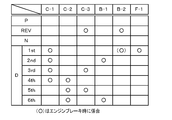
- FIG. 1 is a configuration diagram illustrating a schematic configuration of an automobile 10. 4 is an explanatory diagram showing an operation table of the speed change mechanism 40.
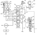
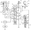
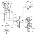
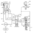
- FIG. It is a block diagram which shows the outline of a structure of the hydraulic control apparatus 50 as one Example of this invention. It is explanatory drawing explaining operation
- FIG. 1 is a block diagram showing an outline of the configuration of the automobile 10
- FIG. FIG. 3 is a block diagram showing an outline of the configuration of the hydraulic control device 50 as an embodiment of the present invention.
- FIG. 4 shows the hydraulic control device 50 of the embodiment when the lockup clutch 37 is released.
- FIG. 5 is an explanatory diagram for explaining the operation of the hydraulic control apparatus 50 according to the embodiment when the lockup clutch 37 is engaged.
- an automobile 10 includes an engine 12 as an internal combustion engine that outputs power by explosion combustion of hydrocarbon fuel such as gasoline and light oil, and an engine electronic control unit (engine) that controls the operation of the engine 12.
- ECU engine electronic control unit
- ECU engine electronic control unit
- An automatic transmission electronic control unit (ATECU) 16 for controlling the automatic transmission 20 and a main electronic control unit (main ECU) 90 for controlling the entire vehicle are provided.
- the main EUC 90 includes a shift position SP from the shift position sensor 92 that detects the operation position of the shift lever, an accelerator opening Acc from the accelerator pedal position sensor 94 that detects the amount of depression of the accelerator pedal, and depression of the brake pedal.
- the brake switch signal BSW from the brake switch 96 to be detected, the vehicle speed V from the vehicle speed sensor 98, and the like are input via the input port.
- the main ECU 90 communicates with the engine ECU 15 and the ATECU 16 via a communication port, and exchanges various control signals and data with the engine ECU 15 and the ATECU 16.
- the automatic transmission 20 includes a torque converter 30 with a lockup clutch that includes an input-side pump impeller 32 connected to the crankshaft 14 of the engine 12 and an output-side turbine runner 33, and torque.
- the input shaft 22 connected to the turbine runner 33 of the converter 30 and the output shaft 24 connected to the axles 18a and 18b via the gear mechanism 26 and the differential gear 28 are used to shift the power input to the input shaft 22.
- a stepped transmission mechanism 40 that outputs to the output shaft 24 and a hydraulic control device 50 (see FIG. 3) of the present embodiment that controls the torque converter 30 and the transmission mechanism 40 are provided.
- the speed change mechanism 40 is configured as a stepped speed change mechanism with six speed changes, and includes a single pinion type planetary gear mechanism, a Ravigneaux type planetary gear mechanism, three clutches C1, C2, C3, and two brakes B1, B2. And a one-way clutch F1.
- the single pinion type planetary gear mechanism includes a sun gear 41 as an external gear, a ring gear 42 as an internal gear arranged concentrically with the sun gear 41, and a plurality of gears meshed with the sun gear 41 and meshed with the ring gear 42.
- a pinion gear 43 and a carrier 44 that holds the plurality of pinion gears 43 so as to rotate and revolve freely are provided.
- the sun gear 41 is fixed to the case, and the ring gear 42 is connected to the input shaft 22.
- the Ravigneaux type planetary gear mechanism is engaged with two sun gears 46a and 46b of external gears, a ring gear 47 of internal gears, a plurality of short pinion gears 48a meshing with the sun gear 46a, a sun gear 46b and a plurality of short pinion gears 48a.
- a plurality of long pinion gears 48b meshing with the ring gear 47 and a carrier 49 that connects the plurality of short pinion gears 48a and the plurality of long pinion gears 48b and holds them in a rotatable and revolving manner are provided, and the sun gear 46a is interposed via the clutch C1.
- the sun gear 46b is connected to the carrier 44 via the clutch C3 and to the case via the brake B1, and the ring gear 47 is connected to the output shaft 24.
- Cat Ya 49 is connected to the input shaft 22 via the clutch C2.
- the carrier 49 is connected to the case via a one-way clutch F1 and is connected to the case via a brake B2 provided in parallel with the one-way clutch F1.
- the speed change mechanism 40 can switch between forward 1st to 6th speeds, reverse and neutral by a combination of on / off of the clutches C1 to C3 and on / off of the brakes B1 and B2.
- the reverse state can be formed by turning on the clutch C3 and the brake B2 and turning off the clutches C1 and C2 and the brake B1.
- the first forward speed state can be formed by turning on the clutch C1 and turning off the clutches C2 and C3 and the brakes B1 and B2. In this forward first speed state, the brake B2 is turned on during engine braking.
- the second forward speed state can be formed by turning on the clutch C1 and the brake B1 and turning off the clutches C2 and C3 and the brake B2.
- the state of the third forward speed can be formed by turning on the clutches C1 and C3 and turning off the clutch C2 and the brakes B1 and B2.
- the state of the fourth forward speed can be formed by turning on the clutches C1 and C2 and turning off the clutch C3 and the brakes B1 and B2.
- the state of the fifth forward speed can be formed by turning on the clutches C2 and C3 and turning off the clutch C1 and the brakes B1 and B2.
- the sixth forward speed state can be formed by turning on the clutch C2 and the brake B1 and turning off the clutches C1 and C3 and the brake B2.
- the neutral state can be formed by turning off all of the clutches C1 to C3 and the brakes B1 and B2.
- the torque converter 30 is configured as a fluid torque converter with a lock-up clutch.
- a pump impeller 32 connected to the crankshaft 14 of the engine 12 via a converter cover 31, and a pump impeller Turbine runner 33 arranged opposite to 32 and connected to input shaft 22 of automatic transmission 20, and arranged between pump impeller 32 and turbine runner 33, the flow of hydraulic oil from turbine runner 33 to pump impeller 32 is rectified.
- the lockup clutch 37 is configured as a multi-plate clutch capable of locking up and releasing the lockup connecting the pump impeller 32 and the turbine runner 33, and is a clutch fixed to the converter cover 31.
- the clutch plate 38 a slidably supported by the hub
- the clutch plate 38 b slidably supported by the clutch hub connected to the turbine runner 33
- the clutch plates 38 a and 38 b are pressed.
- a clutch piston 39 movably disposed.
- the clutch piston 39 has a lockup oil chamber 39a defined on the back side thereof, and the clutch piston 39 is driven by a differential pressure between the hydraulic oil pressure introduced into the lockup oil chamber 39a and the hydraulic oil pressure in the converter oil chamber 31a.
- the lockup oil chamber 39a is formed with a lockup port 36c for introducing the hydraulic oil or discharging the hydraulic oil.
- the hydraulic control apparatus 50 includes a mechanical oil pump 52 that pumps hydraulic oil from an oil pan 51 to a line pressure oil passage L1 via a strainer 51a by power from an engine, A primary regulator valve 53 that adjusts the pressure of the hydraulic oil pumped to the oil passage L1 to generate the line pressure PL and outputs surplus hydraulic oil accompanying the generation of the line pressure PL to the secondary pressure oil passage L2, and a secondary pressure A secondary regulator valve 54 for adjusting the pressure of the hydraulic oil in the oil passage L2 to generate the secondary pressure Psec and outputting surplus hydraulic oil accompanying the generation of the secondary pressure Psec to the secondary exhaust pressure oil passage L3, and the line pressure PL A modulator valve 55 that generates a modulator pressure Pmod by lowering the pressure, and a modulator valve 55
- the lock-up clutch 37 is engaged with the linear solenoid valve SLT that regulates the modulator pressure Pmod to generate the signal pressure Pslt for operating the primary regulator valve 53 and the secondary regulator valve 54, and the line pressure PL of the line
- Lockup control valve 60 that generates and outputs control pressure Pcl for output
- lockup relay valve 70 that switches the path of hydraulic oil that is supplied to and discharged from torque converter 30, and modulator pressure Pmod to adjust and lock up
- a linear solenoid valve SLU that generates a signal pressure Pslu for operating the control valve 60 and the lockup relay valve 70.
- the linear solenoid valve SLT and the linear solenoid valve SLU are controlled by the ATECU 16.
- the ATECU 16 is configured as a microprocessor centered on a CPU. In addition to the CPU, a ROM that stores a processing program, a RAM that temporarily stores data, an input / output port, a communication port, and the like Is provided.
- the AT ECU 16 communicates with the main ECU 90 and exchanges control signals and data with each other.
- the line pressure PL is individually supplied to the clutches C1 to C3 and the brakes B1 and B2 via corresponding linear solenoid valves (not shown).
- the linear solenoid valve adjusts the line pressure PL so that the corresponding clutch or brake has a torque capacity that can transmit the input torque from the input shaft 22 of the automatic transmission 20 to the output shaft 24. Supply.
- the lock-up control valve 60 is a pressure regulating valve that is operated by the signal pressure Pslu from the linear solenoid valve SLU, and as shown in FIG. 3, the sleeve 62 in which various ports are formed and the communication between the corresponding ports are blocked. And a spring 66 that urges the spool 64 downward in the figure.
- a signal pressure input port 62a for inputting the signal pressure Pslu from the linear solenoid valve SLU, an input port 62b connected to the line pressure oil passage L1 for inputting the line pressure PL, and a line pressure
- An output port 62c that regulates PL and outputs it as a control pressure Pcl to the control pressure oil passages L4 and L5, and a feedback port 62d that inputs the output pressure of the output port 62c as a feedback pressure that urges the spool 64 downward in the figure.
- the signal pressure input port 62a is formed at a position sandwiched between two lands formed on the spool 64 and having different outer diameters.
- the signal pressure input to the signal pressure input port 62a is the difference in area (outside diameter difference) between the pressure receiving surfaces of the two lands, the large-diameter land on the upper side in the figure and the small-diameter land on the lower side in the figure. As a result, it acts as a force for urging the spool 64 upward in the drawing. Accordingly, the spool 64 is urged upward in the figure by the signal pressure Pslu input to the signal pressure input port 62a, and downward in the figure by the spring force of the spring 66 and the feedback pressure input to the feedback port 62d. Be energized. In the lock-up control valve 60, the larger the signal pressure Pslu, the larger the communication area between the input port 62b and the output port 62c by moving the spool 64 upward in the figure so that the control pressure Pcl becomes higher. Adjust pressure.
- An orifice 68 is formed in the control pressure oil passage L5, and the control pressure Pcl output from the output port 62c of the lockup control valve 60 is reduced by the orifice 68 to the lockup relay valve 70 (input port 72c). It comes to be supplied.
- the lockup relay valve 70 is a switching valve that is operated by a signal pressure Pslu from the linear solenoid valve SLU to switch a hydraulic pressure supply / exhaust path, and corresponds to a sleeve 72 in which various ports are formed as shown in FIG. A spool 74 that communicates and shuts off the ports, and a spring 76 that biases the spool 74 upward in the figure.
- the sleeve 72 is connected to a signal pressure input port 72a for inputting the signal pressure Pslu from the linear solenoid valve SLU as various ports, and an output port 62c of the lockup control valve 60 via a control pressure oil passage L4.
- the control pressure Pcl output from the output port 62c connected to the input port 72b for inputting the control pressure Pcl from 62c and the output port 62c of the lockup control valve 60 via the control pressure oil passage L5 is reduced by the orifice 68.
- An input port 72c for inputting the hydraulic pressure an input port 72d connected to the secondary pressure oil passage L2 for inputting the secondary pressure Psec, and an input port 72e connected to the secondary exhaust pressure oil passage L3 for inputting the secondary exhaust pressure Pex.
- And input for circulation of the torque converter 30 An output port 72f connected to the port 36a via the circulation input oil passage L6, an input port 72g connected to the circulation output port 36b of the torque converter 30 via the circulation output oil passage L7, and a torque converter.
- Output port 72h connected to 30 lockup port 36c via lockup oil passage L8, relief port 72i connected to relief oil passage L9 to which relief valve 78 is attached, a cooler (COOLER) ) 88 is connected to the lubricating oil passage L10 to which 88 is attached, and an input port 72k connected to the branch oil passage L11 branched from the circulating output oil passage L7.
- a lubrication target 89 is connected to the subsequent stage of the cooler 88, and the hydraulic oil output to the lubrication oil passage L10 is supplied to the lubrication target 89 after being cooled by the cooler 88.
- the spool 74 is moved upward in FIG. Therefore, the communication between the input port 72b and the output port 72h is blocked, the communication between the input port 72c and the output port 72f is blocked, the communication between the input port 72d and the output port 72f, and the input port 72e and the lubrication port.
- the communication with 72j is cut off, the input port 72g and the lubrication port 72j are connected, the communication between the input port 72g and the relief port 72i is cut off, and the input port 72k and the output port 72h are connected.
- the secondary pressure oil passage L2 to which the input port 72d is connected and the circulation input oil passage L6 to which the output port 72f is connected communicate with the circulation output oil passage L7 to which the input port 72g is connected and the lubrication.
- the lubricating oil passage L10 to which the port 72j is connected communicates.
- the circulation output oil passage L7 since the circulation output oil passage L7 is also connected to the input port 72k via the branch oil passage L11, the circulation output oil passage L7 also communicates with the lockup oil passage L8 to which the output port 72h is connected.
- the release of the lockup clutch 37 can be formed by turning off the linear solenoid valve SLU and setting the spool 74 of the lockup relay valve 70 to the state shown in FIG. In this state, as described above, the secondary pressure oil passage L2 and the circulation input oil passage L6 communicate with each other, and the circulation output oil passage L7 and the lubrication oil passage L10 communicate with each other. Is supplied to the converter oil chamber 31a of the torque converter 30 through the circulation input oil passage L6 and is sent from the converter oil chamber 31a to the cooler 88 through the circulation output oil passage L7 and the lubrication oil passage L10.
- the circulation output oil passage L7 is also communicated with the lockup oil passage L8 via the branch oil passage L11, a part of the hydraulic oil output to the circulation output oil passage L7 is part of the branch oil passage L11. Then, the oil is supplied to the lockup oil chamber 39a through the lockup oil passage L8.
- the lockup oil chamber 39a and the lockup oil passage L7 are filled with hydraulic oil.
- the hydraulic oil supplied to the lockup oil chamber 39a is downstream hydraulic oil after passing through the converter oil chamber 31a, and the hydraulic pressure in the lockup oil chamber 39a is higher than the hydraulic pressure in the converter oil chamber 31a. Therefore, the lockup clutch 37 does not generate an engagement force.
- the lock-up clutch 37 is engaged by turning on the linear solenoid valve SLU to bring the spool 74 of the lock-up relay valve 70 into the state shown in FIG. 5 and the pressure difference between the oil pressure in the lock-up oil chamber 39a and the oil pressure in the converter oil chamber 31a.
- the lockup control valve 60 is controlled by adjusting the signal pressure Pslu output from the linear solenoid valve SLU so as to achieve the target hydraulic pressure.
- control pressure oil passage L4 and the lockup oil passage L8 communicate with each other
- control pressure oil passage L5 and the circulation input oil passage L6 communicate with each other
- the circulation output oil passage L7 Since the relief oil passage L9 communicates, the control pressure Pcl output from the output port 62c of the lockup control valve 60 is used as an engagement pressure for engaging the lockup clutch 37.
- the hydraulic fluid supplied to the lockup oil chamber 39a via the oil passage L8, and pumped by the hydraulic pressure output from the output port 62c of the lockup control valve 60 and depressurized by the orifice 68 is the control pressure oil passage L5.
- the hydraulic oil that is supplied to the converter oil chamber 31a via the input oil passage L6 and passes through the converter oil chamber 31a is supplied to the output oil passage L7 for circulation.
- -Safe oil passage L9 is drained through the relief valve 78. That is, the control pressure Pcl acts on the lock-up oil chamber 39a, and the converter oil chamber 31a is acted on by reducing the control pressure Pcl with the orifice 68, so that the space between the lock-up oil chamber 39a and the converter oil chamber 31a Thus, a differential pressure of the hydraulic pressure is generated, and the lockup clutch 37 can be engaged.
- the engagement pressure of the lockup clutch 37 is controlled by the signal pressure from the linear solenoid valve SLU because the above-described differential pressure increases as the control pressure Pcl increases and decreases as the control pressure Pcl decreases. This can be done by operating the valve 60 and adjusting the control pressure Pcl.
- the lockup clutch 37 is released, a part of the hydraulic fluid that circulates through the converter oil chamber 31a and is output to the circulation output oil passage L7 is locked via the lockup oil passage L8. Since the oil is supplied to the up oil chamber 39a, the lock up oil chamber 39a and the lock up oil passage L7 are filled with hydraulic oil.
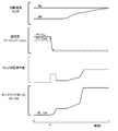
- FIG. 6 shows the engine rotation speed Ne, the turbine rotation speed Nt, the circulation input pressure PT / Cin, the circulation output pressure PT / Cout, and the lockup on when the lockup clutch 37 is engaged using the hydraulic control apparatus of the comparative example.
- FIG. 7 is an explanatory diagram showing how the pressure PL-ON changes with time.
- FIG. 7 shows the engine rotational speed Ne and the turbine rotational speed Nt when the lockup clutch 37 is engaged using the hydraulic control device 50 of the embodiment. It is explanatory drawing which shows the mode of the time change of the circulation input pressure PT / Cin, the circulation output pressure PT / Cout, and the lockup ON pressure PL-ON.
- the branch oil passage L11 in the hydraulic control device 50 of the embodiment is omitted, and the relief oil passage L9 is provided in the input port 72k of the lockup relay valve 70 instead of the branch oil passage L11. It was set as the structure connected.
- the turbine rotation speed Nr indicates the rotation speed of the input shaft 22
- the circulation input pressure PT / Cin indicates the input pressure input to the circulation input port 36a
- the circulation output pressure PT / Cout indicates the circulation output.
- the circulation output oil passage L7 is connected to the input port 72k of the lockup relay valve 70 via the branch oil passage L11.
- the input port 72k is connected.
- the output port 72h connected to the lockup oil passage L8, and when the lockup clutch 37 is released, the communication between the input port 72k and the output port 72h is cut off.
- the lockup clutch 37 is released, a part of the hydraulic fluid that circulates through the converter oil chamber 31a and is output to the circulation output oil passage L7 passes through the branch oil passage L11 and the lockup oil passage L7.
- the lockup oil chamber 39a and the lockup oil passage L7 can be filled with the working oil. Therefore, when the next lock-up clutch 37 is engaged, the hydraulic pressure in the lock-up oil chamber 39a can be quickly raised without executing a fast fill that temporarily raises the hydraulic pressure command of the linear solenoid valve SLU. As a result, the lock-up clutch 37 can be engaged smoothly while reducing the power consumption of the linear solenoid valve SLU.
- the lockup oil chamber 39a when the lockup clutch 37 is released, a part of the hydraulic oil circulated through the converter oil chamber 31a and output to the circulation output oil passage L7 is supplied to the lockup oil chamber 39a.
- the hydraulic oil may be partially supplied to the lockup oil chamber 39a through the circulation input oil passage L6 before circulating through the converter oil chamber 31a.
- the circulation input oil passage L6 and the lockup relay valve 70 are connected instead of the configuration in which the circulation output oil passage L7 and the input port 72k of the lockup relay valve 70 are connected via the branch oil passage L11.
- a configuration may be adopted in which the input port 72k is connected via a branch oil passage and an orifice is formed in the branch oil passage.
- the line pressure PL is used as the source pressure of the control pressure Pcl supplied to the lockup oil chamber 39a when the lockup clutch 37 is engaged.
- the present invention is not limited to this, and the control pressure Pcl is not limited thereto.
- the secondary pressure Psec may be used as the source pressure.
- the control pressure Pcl when the lockup clutch 37 is engaged, the control pressure Pcl is supplied to the lockup oil chamber 39a and the hydraulic pressure obtained by reducing the control pressure Pcl by the orifice 68 as the circulation pressure is supplied to the converter oil chamber 31a.
- the present invention is not limited to this.
- the control pressure Pcl may be supplied to the lockup oil chamber 39a and the secondary pressure Psec may be supplied to the converter oil chamber 31a as the circulation pressure.
- the control pressure Pcl may be supplied to the oil chamber 39a, and the converter oil chamber 31a may be supplied with a hydraulic pressure obtained by reducing the secondary pressure Psec using an orifice as a circulation pressure.
- the secondary pressure Psec is used as the original pressure of the circulating pressure for circulating the converter oil chamber 31a when the lockup clutch 37 is released.
- the hydraulic pressure reduced by the orifice may be used, or the hydraulic pressure obtained by reducing the line pressure PL by the orifice may be used.
- both the lockup control valve 60 and the lockup relay valve 70 are controlled by the signal pressure Pslu from one linear solenoid SLU.
- the present invention is not limited to this, and the signal pressure from a separate linear solenoid is controlled.
- the lock-up control valve 60 and the lock-up relay valve 70 may be separately controlled.
- a single lockup relay valve 70 is used to switch the hydraulic supply / discharge path for the circulation input oil path L6, the circulation output oil path L8, and the lockup oil path L7 of the torque converter 30.
- it may be performed using a plurality of relay valves.
- the hydraulic oil is supplied to the converter oil chamber 31a (circulation input port 36a) using the hydraulic pressure obtained by reducing the line pressure by the orifice 68 when the lockup clutch 37 is engaged.
- the hydraulic oil may be supplied to the converter oil chamber 31a (circulation input port 36a) using the secondary pressure Psec even when the lockup clutch 37 is engaged.
- FIGS. FIG. 8 shows the state of the hydraulic control device 150 when the lockup clutch 37 is released (lockup off), and FIG. 9 shows the hydraulic control device 150 when the lockup clutch 37 is engaged (lockup on). Shows the state.
- the hydraulic control device 150 mainly includes a point that the secondary pressure oil passage L2 is directly connected to the circulation input port 36a, a point that a lockup relay valve 170 is provided instead of the lockup relay valve 70, and circulation.
- the output oil passage L7 and the lubricating oil passage L10 are directly connected to the hydraulic control device 50 of the embodiment.
- the lock-up relay valve 170 according to the modification includes a signal pressure input port 172a for inputting the signal pressure Pslu from the linear solenoid valve SLU, two input ports 172b and 172c, and an output port 172d.
- a switching valve provided with a sleeve 172 formed with, a spool 174 that communicates and blocks the corresponding input / output ports, and a spring 176 that biases the spool 174 in a direction opposite to the direction in which the signal pressure Pslu acts. It is.
- a control pressure oil passage L4 is connected to the input port 172b, a branch oil passage L11 is connected to the input port 172c, and a lockup oil passage L8 is connected to the output port 172d.
- the secondary pressure oil passage L2 since the secondary pressure oil passage L2 is directly connected to the circulation input port 36a, the secondary pressure Psec always acts on the converter oil chamber 31a. Then, the lockup clutch 37 is released by turning off the linear solenoid valve SLU and setting the spool 174 of the lockup relay valve 170 to the state shown in FIG. In this state, the branch oil passage L11 and the lockup oil passage L8 communicate with each other, and therefore, part of the hydraulic oil after passing through the converter oil chamber 31a by the secondary pressure Psec is the branch oil passage L11 and the lockup oil. The oil is supplied to the lockup oil chamber 39a via the path L8. Therefore, in this state, the lockup oil chamber 39a and the lockup oil passage L7 are filled with hydraulic oil.
- the lock-up clutch 37 is engaged by turning on the linear solenoid valve SLU to bring the spool 174 of the lock-up relay valve 170 into the state shown in FIG. 9, and the difference between the oil pressure in the lock-up oil chamber 39a and the oil pressure in the converter oil chamber 31a.
- the lockup control valve 60 is controlled by adjusting the signal pressure Pslu output from the linear solenoid valve SLU so that the pressure becomes the target hydraulic pressure. In this state, the communication between the branch oil passage L11 and the lockup oil passage L8 is interrupted, and the control pressure oil passage L4 and the lockup oil passage L8 communicate with each other, so that the output port 62c of the lockup control valve 60 is connected.
- the output control pressure Pcl is supplied as an engagement pressure to the lockup oil chamber 39a through the control pressure oil passage L4 and the lockup oil passage L8.
- the lockup clutch 37 is engaged by controlling the lockup control valve 60 so that the control pressure Pcl is higher than the secondary pressure Psec. Can be combined.
- the lockup clutch 37 is released, the lockup oil chamber 39a and the lockup oil passage L7 are filled with hydraulic oil, so that when the control pressure Pcl acts on the lockup oil chamber 39a, the lockup clutch chamber 37a is locked up.
- the oil pressure in the oil chamber 39a can be quickly raised, and the lockup clutch 37 can be engaged smoothly.
- the converter oil chamber 31a corresponds to the “circulation oil chamber”
- the lockup oil chamber 39a corresponds to the “engagement oil chamber”
- the lockup control valve 60 corresponds to the “pressure regulating valve”.
- the lock-up relay valve 70 corresponds to a “switch”.
- the control pressure oil passage L4 corresponds to the “control pressure oil passage”
- the circulation input oil passage L6 corresponds to the “circulation input oil passage”
- the circulation output oil passage L7 corresponds to the “circulation output oil passage”.
- the lockup oil passage L8 corresponds to the “engagement oil passage”.
- the “switching device” may include a linear solenoid SLT. That is, the interpretation of the invention described in the Summary of Invention column should be made based on the description in that column, and the examples are only specific examples of the invention described in the Summary of Invention column. It is.
- the present invention is applicable to the manufacturing industry of hydraulic control devices.
Landscapes
- Engineering & Computer Science (AREA)
- General Engineering & Computer Science (AREA)
- Mechanical Engineering (AREA)
- Physics & Mathematics (AREA)
- Fluid Mechanics (AREA)
- Control Of Fluid Gearings (AREA)
Abstract
Description
作動油を入力する循環用入力ポートと作動油を出力する循環用出力ポートとを有し該循環用入力ポートおよび該循環用出力ポートを介して作動油が循環する循環油室と、作動油を入出力する係合用ポートを有する係合油室とが形成され、前記循環油室内の油圧と、前記係合油室内の油圧との差圧により係合するロックアップクラッチを備える流体伝動装置に対して給排する油圧を制御する油圧制御装置であって、
元圧を調圧して前記循環油室内の油圧よりも高い制御圧を生成して前記係合用ポートに供給可能な調圧バルブを備え、
前記ロックアップクラッチを解放する場合には、前記循環用入力ポートおよび前記循環用出力ポートを介して前記循環油室に作動油を循環させながら該循環油室を循環する作動油の一部を前記係合用ポートに供給し、前記ロックアップクラッチを係合する場合には、前記循環油室を循環する作動油の前記係合用ポートへの供給を遮断すると共に該係合用ポートへ前記制御圧を供給する
ことを要旨とする。
作動油を入力する循環用入力ポートと作動油を出力する循環用出力ポートとを有し該循環用入力ポートおよび該循環用出力ポートを介して作動油が循環する循環油室と、作動油を入出力する係合用ポートを有する係合油室とが形成され、前記循環油室内の油圧と、前記係合油室内の油圧との差圧により係合するロックアップクラッチを備える流体伝動装置に対して給排する油圧を制御する油圧制御方法であって、
前記ロックアップクラッチを解放する場合には、前記循環用入力ポートおよび前記循環用出力ポートを介して前記循環油室に作動油を循環させながら該循環油室を循環する作動油の一部を前記係合用ポートに供給し、前記ロックアップクラッチを係合する場合には、前記循環油室を循環する作動油の前記係合用ポートへの供給を遮断すると共に該係合用ポートへ前記循環油室内の油圧よりも高い制御圧を供給する
ことを要旨とする。
Claims (5)
- 作動油を入力する循環用入力ポートと作動油を出力する循環用出力ポートとを有し該循環用入力ポートおよび該循環用出力ポートを介して作動油が循環する循環油室と、作動油を入出力する係合用ポートを有する係合油室とが形成され、前記循環油室内の油圧と、前記係合油室内の油圧との差圧により係合するロックアップクラッチを備える流体伝動装置に対して給排する油圧を制御する油圧制御装置であって、
元圧を調圧して前記循環油室内の油圧よりも高い制御圧を生成して前記係合用ポートに供給可能な調圧バルブを備え、
前記ロックアップクラッチを解放する場合には、前記循環用入力ポートおよび前記循環用出力ポートを介して前記循環油室に作動油を循環させながら該循環油室を循環する作動油の一部を前記係合用ポートに供給し、前記ロックアップクラッチを係合する場合には、前記循環油室を循環する作動油の前記係合用ポートへの供給を遮断すると共に該係合用ポートへ前記制御圧を供給する
ことを特徴とする油圧制御装置。 - 請求項1記載の油圧制御装置であって、
前記循環用入力ポートおよび前記循環用出力ポートを介して前記循環油室に作動油を循環させながら該循環油室を循環する作動油の一部を前記係合用ポートへ供給する第1の状態と、前記循環油室を循環する作動油の前記係合用ポートへの供給を遮断する第2の状態とを切り替える切替器を備え、
前記ロックアップクラッチを解放する場合には、前記切替器を前記第1の状態として前記調圧バルブから前記係合用ポートへの前記制御圧の供給を遮断し、前記ロックアップクラッチを係合する場合には、前記切替器を前記第2の状態として前記調圧バルブから前記係合用ポートへ前記制御圧を供給する
ことを特徴とする油圧制御装置。 - 請求項2記載の油圧制御装置であって、
前記切替器は、前記第1の状態として、前記循環用出力ポートから排出された作動油が前記係合用ポートへ供給されるよう構成されてなる
ことを特徴とする油圧制御装置。 - 請求項3記載の油圧制御装置であって、
前記調圧バルブの出力ポートに接続された制御圧用油路と、
前記循環用入力ポートに接続された循環用入力油路と、
前記循環用出力ポートに接続された循環用出力油路と、
前記循環用出力油路から分岐する分岐油路と、
前記係合用ポートに接続された係合用油路と、
を備え、
前記切替器は、前記第1の状態として前記分岐油路と前記係合用油路とを連通すると共に前記制御圧用油路と前記係合用油路との連通を遮断し、前記第2の状態として前記分岐油路と前記係合用油路との連通を遮断すると共に前記制御圧用油路と前記係合圧用油路とを連通する
ことを特徴とする油圧制御装置。 - 作動油を入力する循環用入力ポートと作動油を出力する循環用出力ポートとを有し該循環用入力ポートおよび該循環用出力ポートを介して作動油が循環する循環油室と、作動油を入出力する係合用ポートを有する係合油室とが形成され、前記循環油室内の油圧と、前記係合油室内の油圧との差圧により係合するロックアップクラッチを備える流体伝動装置に対して給排する油圧を制御する油圧制御方法であって、
前記ロックアップクラッチを解放する場合には、前記循環用入力ポートおよび前記循環用出力ポートを介して前記循環油室に作動油を循環させながら該循環油室を循環する作動油の一部を前記係合用ポートに供給し、前記ロックアップクラッチを係合する場合には、前記循環油室を循環する作動油の前記係合用ポートへの供給を遮断すると共に該係合用ポートへ前記循環油室内の油圧よりも高い制御圧を供給する
ことを特徴とする油圧制御方法。
Priority Applications (4)
| Application Number | Priority Date | Filing Date | Title |
|---|---|---|---|
| DE112014000753.6T DE112014000753T5 (de) | 2013-03-29 | 2014-03-27 | Hydrauliksteuervorrichtung und Hydrauliksteuerverfahren |
| CN201480010889.XA CN105026803A (zh) | 2013-03-29 | 2014-03-27 | 油压控制装置以及油压控制方法 |
| JP2015508708A JPWO2014157544A1 (ja) | 2013-03-29 | 2014-03-27 | 油圧制御装置および油圧制御方法 |
| US14/770,325 US20160003309A1 (en) | 2013-03-29 | 2014-03-27 | Hydraulic control device and hydraulic control method |
Applications Claiming Priority (2)
| Application Number | Priority Date | Filing Date | Title |
|---|---|---|---|
| JP2013-072586 | 2013-03-29 | ||
| JP2013072586 | 2013-03-29 |
Publications (1)
| Publication Number | Publication Date |
|---|---|
| WO2014157544A1 true WO2014157544A1 (ja) | 2014-10-02 |
Family
ID=51624503
Family Applications (1)
| Application Number | Title | Priority Date | Filing Date |
|---|---|---|---|
| PCT/JP2014/058932 Ceased WO2014157544A1 (ja) | 2013-03-29 | 2014-03-27 | 油圧制御装置および油圧制御方法 |
Country Status (5)
| Country | Link |
|---|---|
| US (1) | US20160003309A1 (ja) |
| JP (1) | JPWO2014157544A1 (ja) |
| CN (1) | CN105026803A (ja) |
| DE (1) | DE112014000753T5 (ja) |
| WO (1) | WO2014157544A1 (ja) |
Cited By (1)
| Publication number | Priority date | Publication date | Assignee | Title |
|---|---|---|---|---|
| WO2022228594A1 (de) * | 2021-04-28 | 2022-11-03 | Schaeffler Technologies AG & Co. KG | Verfahren zur steuerung einer hydraulikvorrichtung |
Families Citing this family (2)
| Publication number | Priority date | Publication date | Assignee | Title |
|---|---|---|---|---|
| KR20180095915A (ko) * | 2016-02-25 | 2018-08-28 | 아이신에이더블류 가부시키가이샤 | 차량용 전동 장치의 유압 제어 장치 |
| JP6502991B2 (ja) | 2017-03-29 | 2019-04-17 | 本田技研工業株式会社 | 油圧制御装置 |
Citations (5)
| Publication number | Priority date | Publication date | Assignee | Title |
|---|---|---|---|---|
| JP2001173764A (ja) * | 1999-12-20 | 2001-06-26 | Aisin Aw Co Ltd | 自動変速機の油圧制御装置 |
| JP2003042287A (ja) * | 2001-07-31 | 2003-02-13 | Aisin Aw Co Ltd | 自動変速機の油圧制御装置 |
| JP2006349007A (ja) * | 2005-06-14 | 2006-12-28 | Aisin Aw Co Ltd | 自動変速機の油圧制御装置 |
| JP2011021696A (ja) * | 2009-07-16 | 2011-02-03 | Aisin Seiki Co Ltd | 流体伝動装置の油圧制御装置 |
| JP2012197870A (ja) * | 2011-03-22 | 2012-10-18 | Aisin Aw Co Ltd | 油圧制御装置 |
Family Cites Families (5)
| Publication number | Priority date | Publication date | Assignee | Title |
|---|---|---|---|---|
| JP4577342B2 (ja) * | 2007-09-10 | 2010-11-10 | トヨタ自動車株式会社 | 油圧制御装置 |
| JP4781336B2 (ja) * | 2007-09-10 | 2011-09-28 | トヨタ自動車株式会社 | 油圧制御装置 |
| JP5045385B2 (ja) * | 2007-11-16 | 2012-10-10 | トヨタ自動車株式会社 | ロックアップクラッチの油圧制御装置 |
| JP2009243640A (ja) * | 2008-03-31 | 2009-10-22 | Aisin Aw Co Ltd | 発進装置の油圧制御装置 |
| JP2011094786A (ja) * | 2009-09-29 | 2011-05-12 | Aisin Aw Co Ltd | 自動変速機の油圧制御装置 |
-
2014
- 2014-03-27 JP JP2015508708A patent/JPWO2014157544A1/ja active Pending
- 2014-03-27 WO PCT/JP2014/058932 patent/WO2014157544A1/ja not_active Ceased
- 2014-03-27 CN CN201480010889.XA patent/CN105026803A/zh active Pending
- 2014-03-27 DE DE112014000753.6T patent/DE112014000753T5/de not_active Withdrawn
- 2014-03-27 US US14/770,325 patent/US20160003309A1/en not_active Abandoned
Patent Citations (5)
| Publication number | Priority date | Publication date | Assignee | Title |
|---|---|---|---|---|
| JP2001173764A (ja) * | 1999-12-20 | 2001-06-26 | Aisin Aw Co Ltd | 自動変速機の油圧制御装置 |
| JP2003042287A (ja) * | 2001-07-31 | 2003-02-13 | Aisin Aw Co Ltd | 自動変速機の油圧制御装置 |
| JP2006349007A (ja) * | 2005-06-14 | 2006-12-28 | Aisin Aw Co Ltd | 自動変速機の油圧制御装置 |
| JP2011021696A (ja) * | 2009-07-16 | 2011-02-03 | Aisin Seiki Co Ltd | 流体伝動装置の油圧制御装置 |
| JP2012197870A (ja) * | 2011-03-22 | 2012-10-18 | Aisin Aw Co Ltd | 油圧制御装置 |
Cited By (1)
| Publication number | Priority date | Publication date | Assignee | Title |
|---|---|---|---|---|
| WO2022228594A1 (de) * | 2021-04-28 | 2022-11-03 | Schaeffler Technologies AG & Co. KG | Verfahren zur steuerung einer hydraulikvorrichtung |
Also Published As
| Publication number | Publication date |
|---|---|
| CN105026803A (zh) | 2015-11-04 |
| JPWO2014157544A1 (ja) | 2017-02-16 |
| US20160003309A1 (en) | 2016-01-07 |
| DE112014000753T5 (de) | 2015-10-15 |
Similar Documents
| Publication | Publication Date | Title |
|---|---|---|
| JP5692416B2 (ja) | スプール弁および潤滑油供給装置 | |
| WO2010082423A1 (ja) | 動力伝達装置およびこれを搭載する車両 | |
| WO2010087091A1 (ja) | 動力伝達装置およびこれを搭載する車両 | |
| JP5556712B2 (ja) | 油圧制御装置 | |
| JP5742966B2 (ja) | 潤滑油供給装置 | |
| US20120000740A1 (en) | Hydraulic pressure control device | |
| JP5668870B2 (ja) | 油圧制御装置 | |
| JPWO2014157544A1 (ja) | 油圧制御装置および油圧制御方法 | |
| JP2014020442A (ja) | 油圧制御装置 | |
| JP5482251B2 (ja) | ロックアップクラッチ装置およびその制御方法 | |
| US20110302915A1 (en) | Hydraulic pressure control device | |
| JPWO2014156944A1 (ja) | 油圧制御装置 | |
| JP5233693B2 (ja) | 動力伝達装置およびこれを搭載する車両 | |
| JP2014126074A (ja) | 潤滑油供給装置 | |
| JP6217558B2 (ja) | 車両用動力伝達装置の油圧制御回路 | |
| JP2013174259A (ja) | 自動変速機の油圧制御装置 | |
| JP2013245770A (ja) | 油圧制御装置 | |
| JP2011214616A (ja) | 油圧制御装置 |
Legal Events
| Date | Code | Title | Description |
|---|---|---|---|
| WWE | Wipo information: entry into national phase |
Ref document number: 201480010889.X Country of ref document: CN |
|
| 121 | Ep: the epo has been informed by wipo that ep was designated in this application |
Ref document number: 14774775 Country of ref document: EP Kind code of ref document: A1 |
|
| ENP | Entry into the national phase |
Ref document number: 2015508708 Country of ref document: JP Kind code of ref document: A |
|
| WWE | Wipo information: entry into national phase |
Ref document number: 14770325 Country of ref document: US Ref document number: 1120140007536 Country of ref document: DE Ref document number: 112014000753 Country of ref document: DE |
|
| 122 | Ep: pct application non-entry in european phase |
Ref document number: 14774775 Country of ref document: EP Kind code of ref document: A1 |