WO2014156095A1 - 非水電解質二次電池 - Google Patents
非水電解質二次電池 Download PDFInfo
- Publication number
- WO2014156095A1 WO2014156095A1 PCT/JP2014/001626 JP2014001626W WO2014156095A1 WO 2014156095 A1 WO2014156095 A1 WO 2014156095A1 JP 2014001626 W JP2014001626 W JP 2014001626W WO 2014156095 A1 WO2014156095 A1 WO 2014156095A1
- Authority
- WO
- WIPO (PCT)
- Prior art keywords
- negative electrode
- binder
- electrolyte secondary
- secondary battery
- active material
- Prior art date
- Legal status (The legal status is an assumption and is not a legal conclusion. Google has not performed a legal analysis and makes no representation as to the accuracy of the status listed.)
- Ceased
Links
Images


Classifications
-
- H—ELECTRICITY
- H01—ELECTRIC ELEMENTS
- H01M—PROCESSES OR MEANS, e.g. BATTERIES, FOR THE DIRECT CONVERSION OF CHEMICAL ENERGY INTO ELECTRICAL ENERGY
- H01M4/00—Electrodes
- H01M4/02—Electrodes composed of, or comprising, active material
- H01M4/62—Selection of inactive substances as ingredients for active masses, e.g. binders, fillers
- H01M4/621—Binders
- H01M4/622—Binders being polymers
-
- H—ELECTRICITY
- H01—ELECTRIC ELEMENTS
- H01M—PROCESSES OR MEANS, e.g. BATTERIES, FOR THE DIRECT CONVERSION OF CHEMICAL ENERGY INTO ELECTRICAL ENERGY
- H01M4/00—Electrodes
- H01M4/02—Electrodes composed of, or comprising, active material
- H01M4/13—Electrodes for accumulators with non-aqueous electrolyte, e.g. for lithium-accumulators; Processes of manufacture thereof
-
- H—ELECTRICITY
- H01—ELECTRIC ELEMENTS
- H01M—PROCESSES OR MEANS, e.g. BATTERIES, FOR THE DIRECT CONVERSION OF CHEMICAL ENERGY INTO ELECTRICAL ENERGY
- H01M4/00—Electrodes
- H01M4/02—Electrodes composed of, or comprising, active material
- H01M2004/026—Electrodes composed of, or comprising, active material characterised by the polarity
- H01M2004/027—Negative electrodes
-
- Y—GENERAL TAGGING OF NEW TECHNOLOGICAL DEVELOPMENTS; GENERAL TAGGING OF CROSS-SECTIONAL TECHNOLOGIES SPANNING OVER SEVERAL SECTIONS OF THE IPC; TECHNICAL SUBJECTS COVERED BY FORMER USPC CROSS-REFERENCE ART COLLECTIONS [XRACs] AND DIGESTS
- Y02—TECHNOLOGIES OR APPLICATIONS FOR MITIGATION OR ADAPTATION AGAINST CLIMATE CHANGE
- Y02E—REDUCTION OF GREENHOUSE GAS [GHG] EMISSIONS, RELATED TO ENERGY GENERATION, TRANSMISSION OR DISTRIBUTION
- Y02E60/00—Enabling technologies; Technologies with a potential or indirect contribution to GHG emissions mitigation
- Y02E60/10—Energy storage using batteries
Definitions
- the present invention relates to a non-aqueous electrolyte secondary battery.
- non-aqueous electrolyte secondary batteries have been increasingly demanded for industrial use, such as backup power sources, storage of renewable energy such as solar power generation and wind power generation, in consideration of the problem of power supply insecurity.
- non-aqueous electrolyte secondary batteries are required to have a high capacity and a long life in a large current cycle.
- the adhesion between the electrode mixture layer and the current collector and the adhesion of the active material in the mixture layer are large.
- the battery capacity may be sacrificed.
- Patent Documents 1 to 4 are insufficient.
- An object of the present invention is to provide a non-aqueous electrolyte secondary battery that has a high capacity and a long life in a large current cycle.
- a nonaqueous electrolyte secondary battery includes a negative electrode active material, a binder A containing a rubber-based polymer compound as a binder, and a water-soluble polymer compound on a negative electrode current collector.
- a negative electrode plate having a negative electrode mixture layer formed thereon, and when the cross section in the thickness direction of the negative electrode mixture layer is divided into a current collector side region and a surface side region, The sum of the perimeters of the negative electrode active material per unit area of the cross section is more distributed in the current collector side region than in the surface side region, and the binder A is more distributed in the current collector side region than in the surface side region. ing.
- a non-aqueous electrolyte secondary battery that has a high capacity and a long life in a large current cycle.
- FIG. 1 is a schematic longitudinal sectional view showing a schematic structure of a cylindrical nonaqueous electrolyte secondary battery according to an embodiment of the present invention.
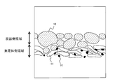
- FIG. 2 is a schematic view showing a cross section of the negative electrode mixture layer of Experimental Example 1.
- FIG. 3 is a schematic view showing a cross section of the negative electrode mixture layer of Experimental Example 5.
- the non-aqueous electrolyte secondary battery according to the present embodiment includes a negative electrode active material, a binder A containing a rubber-based polymer compound as a binder, and a water-soluble polymer compound on a negative electrode current collector.
- the sum of the perimeters of the negative electrode active material per area is more distributed in the current collector side region than in the surface side region, and the binder A is more distributed in the current collector side region than in the surface side region.
- the binder B exists at least around the negative electrode active material.
- a substantially uniform SEI film is formed in the electrode by an appropriate arrangement of the negative electrode active material and the binder, so that the high capacity and high current cycle can be achieved.
- a non-aqueous electrolyte secondary battery capable of obtaining a long life is provided.
- the negative electrode active material disposed on the surface side of the negative electrode mixture layer is less likely to be closely packed and the shape of the negative electrode active material shortens the lithium ion diffusion path and is disposed on the current collector side. It is considered that lithium ions can be easily inserted into and extracted from the negative electrode active material, and the deactivation of lithium ions on the negative electrode active material when charged and discharged with a large current value is suppressed.
- the negative electrode active material group having a large sum of the perimeters arranged on the current collector side is filled with a high density to achieve a high capacity, and the binder A has a liquid collecting performance. It is considered that the electrolyte is retained inside the electrode even when the substance expands and the amount of voids is significantly reduced.
- an SEI film that inactivates and stabilizes the negative electrode active material is formed by reductive decomposition of the electrolytic solution. Since there are many interfaces with a liquid, in order to obtain a substantially uniform film, a lot of electrolytic solutions are required. Therefore, with the sum of the perimeters of the negative electrode active material, by arranging the binder A having a high liquid collection performance to be inclined, uneven formation of the SEI film on the electrode surface side and the current collector side is suppressed, Since lithium ion deactivation is also suppressed, it is considered that the cycle characteristics can be improved.
- the non-aqueous electrolyte secondary battery according to the present embodiment is extremely important in industrial applications where long-term use is desired.
- the sum of the peripheral lengths of the negative electrode active material is the sum of the lengths of the edge portions of the cross sections of the individual negative electrode active material particles per unit area of the cross section of the negative electrode mixture layer.
- the sum of the peripheral lengths of the negative electrode active material can be quantified by image analysis using, for example, a cross-sectional SEM image. That is, a cross-sectional SEM image in the thickness direction of the negative electrode mixture layer is taken, the perimeter of each negative electrode active material particle observed per unit area of the cross-section SEM is acquired, and the sum is obtained. If each negative electrode mixture layer is divided in half into a surface side region and a current collector side region, the abundance ratio can be obtained. In order to obtain the effect of this configuration, the sum of the perimeters of the negative electrode active material observed in the current collector side region is preferably 60% or more with respect to the total amount of the negative electrode active material in the entire negative electrode mixture layer. 70% or more is more preferable.
- the negative electrode active material is not particularly limited as long as it can reversibly store and release lithium.
- a carbon material, a metal or alloy material alloyed with lithium, a metal oxide, or the like may be used. it can.
- the negative electrode on the current collector side As specific means for increasing the sum of the perimeters of the negative electrode active material disposed on the current collector side and reducing the sum of the perimeters of the negative electrode active material disposed on the surface side, for example, the negative electrode on the current collector side
- the active material include the use of the above-described materials such as a lump shape and a flake shape, and an increase in specific surface area by size reduction and surface modification.
- the method of adjusting the particle size distribution of a negative electrode active material and making it easy to fill geometrically is also mentioned.
- a material having a small aspect ratio on the surface side or a material processed into a spherical shape can be used.
- a negative electrode active material having a large sum of perimeters, a binder A in a larger amount than the surface side, a binder B, and a solvent such as water are mixed to form a negative electrode for the current collector side.
- a slurry is prepared, and the negative electrode active material having a small sum of the perimeters, the binder A in a smaller amount than the current collector side, the binder B, and a solvent such as water are mixed to prepare a slurry for the surface side.
- the negative electrode slurry for the surface side is coated on both sides on the layer of the negative electrode slurry for the current collector side
- a negative electrode mixture layer can be formed by coating and drying.
- the amount of the binder A and the binder B changes discontinuously, but before the layer of the negative electrode slurry for the current collector side is completely dried, the negative electrode slurry for the surface side is used. It is good also as a structure which the quantity of the binder A and the binder B changes continuously by forming a layer.
- the shape factor of the negative electrode active material particles represented by the following formula is preferably in the range of 1.0 to less than 2.8 in the surface side region and in the range of 2.8 to 10 in the current collector side region. .
- the shape factor can be obtained using image analysis software (image-Pro Plus Ver. 4.0 (manufactured by Oranetron)).
- image-Pro Plus Ver. 4.0 manufactured by Oranetron
- the maximum length (L) and the projected area (A) are measured for each negative electrode active material particle appearing per unit area of the cross section of the negative electrode mixture layer, the value of the following formula is calculated, and the average value is calculated as the shape. Calculated as a coefficient.
- Shape factor (L 2 / A) ⁇ ( ⁇ / 4) (In the above formula, L represents the maximum length ( ⁇ m) of the negative electrode active material particles, and A represents the projected area ( ⁇ m 2 ) of the negative electrode active material particles.)
- a carbon material that has various shapes and has abundant industrial processing results.
- natural graphite artificial graphite, mesophase pitch-based carbon fiber ( MCF), mesocarbon microbeads (MCMB), coke, hard carbon and the like. That is, it is preferable to use spherical graphite such as MCMB on the surface side and non-spherical graphite such as lump or flakes on the current collector side. In particular, it is more preferable to use massive graphite having a shape factor of 2.8 or more and 5 or less on the current collector side.
- the binder A containing the rubber polymer compound is not particularly limited as long as it is a polymer compound having elasticity, but styrene butadiene rubber, high styrene rubber, ethylene propylene rubber, butyl rubber, chloroprene rubber, butadiene rubber. Rubber binders such as isoprene rubber, acrylonitrile butadiene rubber, acrylonitrile rubber, fluorine rubber, acrylic rubber, and silicone rubber can be used alone or in admixture of two or more.
- the mass ratio of the binder A to the mass of the negative electrode mixture layer is preferably 0.5 to 2% by mass.
- the amount of the binder A present in the current collector side region is preferably 60% or more, more preferably 70% or more of the total amount of the binder A present in the negative electrode mixture layer.
- a method for quantifying the binder A after preparing a cross section of the negative electrode plate with a cross-section polisher, staining with a stain such as osmium tetroxide, an electron probe microanalyzer (Electron Probe Micro Analyzer, abbreviated as EPMA) or In addition, a method of detecting with an energy dispersive X-ray fluorescence analyzer (Energy Dispersive X-ray Spectroscopy, abbreviations: EDX, EDS) or the like is known.
- a stain such as osmium tetroxide, an electron probe microanalyzer (Electron Probe Micro Analyzer, abbreviated as EPMA) or In addition, a method of detecting with an energy dispersive X-ray fluorescence analyzer (Energy Dispersive X-ray Spectroscopy, abbreviations: EDX, EDS) or the like is known.
- the binder B containing the water-soluble polymer compound may be any water-soluble polymer compound, and is not particularly limited.
- the polymer water-soluble polymer compound (hereinafter referred to as “polymer compound”), polysaccharide, One type of water-soluble polymer compound (hereinafter referred to as “polysaccharide compound”) or a mixture of two or more types can be used.
- polymer compound polyvinyl alcohol, polyvinyl pyrrolidone, polyethylene oxide, derivatives thereof and the like can be used.
- As the polysaccharide compound cellulose, carboxymethyl cellulose and the like can be used. Among these, carboxymethylcellulose is preferable from the viewpoint of electrochemical stability.
- the mass ratio of the binder B to the mass of the negative electrode mixture layer is preferably 0.5 to 2 mass%.
- the binder B is present at least around the negative electrode active material in order to ensure adhesion between the negative electrode active materials in the negative electrode mixture layer and to make the SEI film formation substantially uniform. preferable.
- Examples of the positive electrode active material include a lithium-containing transition metal composite oxide containing cobalt, nickel, manganese, aluminum, or the like as a transition metal.
- Examples of lithium-containing transition metal composite oxides containing cobalt, nickel, manganese or aluminum include lithium-cobalt composite oxides, lithium-nickel composite oxides, lithium-nickel-cobalt composite oxides, and lithium-nickel- Examples thereof include a cobalt-aluminum composite oxide and a lithium-nickel-cobalt-manganese composite oxide.
- the type of the lithium-containing transition metal oxide is not limited to the above, and an olivine structure represented by the general formula LiMePO 4 (Me is at least one selected from the group consisting of Fe, Ni, Co, and Mn).
- the lithium-containing transition metal oxide further includes at least one selected from the group consisting of magnesium, aluminum, titanium, chromium, vanadium, iron, copper, zinc, niobium, molybdenum, zirconium, tin, tungsten, sodium, and potassium. You may go out.
- the solvent of the non-aqueous electrolyte is not particularly limited, and a solvent that has been conventionally used for non-aqueous electrolyte secondary batteries can be used.
- cyclic carbonates such as ethylene carbonate, propylene carbonate, butylene carbonate, vinylene carbonate, chain carbonates such as dimethyl carbonate, ethyl methyl carbonate, diethyl carbonate, methyl acetate, ethyl acetate, propyl acetate, methyl propionate, propionic acid
- esters such as ethyl and ⁇ -butyrolactone
- compounds containing sulfone groups such as propane sultone, 1,2-dimethoxyethane, 1,2-diethoxyethane, tetrahydrofuran, 1,2-dioxane, 1,4 -Compounds containing ethers such as dioxane and 2-methyltetrahydrofuran, butyronitrile, valeronitrile
- a solvent in which a part of these H is substituted with F is preferably used.
- these may be used alone or may be used in combination.
- an ionic liquid can also be used as a nonaqueous solvent for the nonaqueous electrolyte.
- the cation species and the anion species are not particularly limited, but low viscosity, electrochemical stability, hydrophobicity, etc.
- a combination using a pyridinium cation, an imidazolium cation, or a quaternary ammonium cation as the cation and a fluorine-containing imide anion as the anion is particularly preferable.
- a solute used for the non-aqueous electrolyte a known lithium salt that has been conventionally used in non-aqueous electrolyte secondary batteries can be used.
- a lithium salt a lithium salt containing one or more elements among P, B, F, O, S, N, and Cl can be used.
- LiPF 6 LiBF 4 , LiCF 3 SO 3 , LiN (FSO 2 ) 2 , LiN (CF 3 SO 2 ) 2 , LiN (C 2 F 5 SO 2 ) 2 , LiN (CF 3 SO 2 ) (C 4 F 9 SO 2 ), Lithium salts such as LiC (C 2 F 5 SO 2 ) 3 , LiAsF 6 , LiClO 4 and mixtures thereof can be used.
- LiPF 6 is preferably used in order to enhance the high rate charge / discharge characteristics and durability of the nonaqueous electrolyte secondary battery.
- separator conventionally used separators can be used. Specifically, not only a separator containing polyethylene, but also a material in which a layer containing polypropylene is formed on the surface of polyethylene or a material in which an aramid resin or the like is applied on the surface of a polyethylene separator may be used.
- a layer containing an inorganic filler that has been conventionally used may be formed at the interface between the positive electrode and the separator and the interface between the negative electrode and the separator.
- the filler it is also possible to use an oxide or phosphate compound using titanium, aluminum, silicon, magnesium or the like conventionally used alone or a plurality thereof, and a material whose surface is treated with a hydroxide or the like. it can.
- the filler layer is formed by a method in which a filler-containing slurry is directly applied to a positive electrode, a negative electrode, or a separator, or a method in which a sheet formed with a filler is attached to a positive electrode, a negative electrode, or a separator. be able to.
- nonaqueous electrolyte secondary battery As described above, according to the nonaqueous electrolyte secondary battery according to the present embodiment, it is possible to provide a nonaqueous electrolyte secondary battery excellent in cycle characteristics at a large current while having a high capacity.
- the nonaqueous electrolyte secondary battery according to the present embodiment includes, for example, a drive power source that requires high output such as an electric vehicle, HEV, and electric tool, storage of regenerative energy such as solar power generation and wind power generation, a backup power source, and the like Development of industrial power supplies that require a long service life can be expected.
- a drive power source that requires high output such as an electric vehicle, HEV, and electric tool
- storage of regenerative energy such as solar power generation and wind power generation
- a backup power source and the like Development of industrial power supplies that require a long service life can be expected.
- Example 1 [Production of positive electrode] 94 parts by mass of lithium nickel cobalt manganate particles represented by LiNi 0.5 Co 0.2 Mn 0.3 O 2 as a positive electrode active material, 4 parts by mass of carbon black as a carbon conductive agent, and polyvinylidene fluoride 2 as a binder A positive electrode slurry was prepared by mixing with parts by mass and adding an appropriate amount of NMP (N-methyl-2-pyrrolidone). Next, the positive electrode slurry was applied to both surfaces of a positive electrode current collector containing aluminum and dried. And it rolled using the roller, it cut out to predetermined electrode size, and also the positive electrode lead was produced by attaching a positive electrode lead.
- NMP N-methyl-2-pyrrolidone
- a negative electrode active material in a surface side region having a small sum of perimeters and a small amount of binder A 100 parts by mass of spherical graphite mesocarbon microbeads (MCMB) and carboxymethyl cellulose as binder B (CMC) 1 part by mass and water were mixed.
- MCMB spherical graphite mesocarbon microbeads
- CMC carboxymethyl cellulose
- SBR styrene butadiene rubber
- the negative electrode slurry (1) was applied to both sides of a negative electrode current collector made of copper foil having a thickness of 12 ⁇ m and dried. Thereafter, the negative electrode slurry (2) was applied on both sides of the layer made of the negative electrode slurry (1) and dried.
- the positive electrode and the negative electrode were arranged to face each other through a separator including a polyethylene microporous film, and then wound in a spiral shape using a winding core.
- a spirally wound electrode body is prepared by pulling out the winding core, and after inserting the electrode body into a metal outer can, the nonaqueous electrolyte solution is injected and further sealed, so that the battery size becomes the diameter.
- a 18650 type nonaqueous electrolyte secondary battery (capacity: 2.0 Ah (measurement conditions of 4.2 V-2.75 V)) of 18 mm and a height of 65 mm was produced.
- the battery thus produced is hereinafter referred to as battery A1.
- FIG. 1 is a schematic cross-sectional view of the non-aqueous electrolyte secondary battery 10 produced as described above.
- Reference numeral 1 is a positive electrode
- 2 is a negative electrode
- 3 is a separator
- 4 is an electrode body
- 5 is a negative electrode.
- a can 6 is a sealing body
- 7 is a positive electrode current collector
- 8 is a negative electrode current collector.
- 12 indicates MCMB, which is spherical graphite
- 14 indicates massive graphite
- 16 indicates SBR, which is binder A.
- Example 2 Experimental example, except that negative electrode slurry (1) using 100 parts by mass of massive graphite powder was used as the negative electrode active material, and negative electrode slurry (2) using 100 parts by mass of massive graphite powder was used as the negative electrode active material. In the same manner as in Example 1, a nonaqueous electrolyte secondary battery was produced. The battery thus produced is hereinafter referred to as battery A2.
- Example 3 A non-aqueous solution was used in the same manner as in Experimental Example 1, except that the negative electrode slurry (1) using 100 parts by mass of MCMB was used as the negative electrode active material and the negative electrode slurry (2) using 100 parts by mass of MCMB was used as the negative electrode active material.
- An electrolyte secondary battery was produced. The battery thus produced is hereinafter referred to as battery A3.
- the negative electrode slurry (1) was prepared with 1 part by mass of styrene butadiene rubber (SBR), and the negative electrode slurry (2) was prepared with 1 part by mass of styrene butadiene rubber (SBR).
- SBR styrene butadiene rubber
- a non-aqueous electrolyte secondary battery was produced.
- the battery thus produced is hereinafter referred to as battery A4.
- FIG. 3 shows a schematic diagram of a cross section of the negative electrode mixture layer.
- Example 6 100 parts by mass of massive graphite powder, 1 part by mass of carboxymethyl cellulose (CMC) as the binder B, and water were mixed. This kneaded material was mixed with 1 part by mass of styrene butadiene rubber (SBR) as binder A and water to prepare a negative electrode slurry (4).
- the negative electrode slurry (4) was applied to both surfaces of a copper foil current collector with a thickness of 12 ⁇ m so as to be equal to the total application amount of the negative electrode slurries (1) and (2) in Experimental Example 1. Thereafter, it was dried, and thereafter, a 18650 battery was produced in the same manner as in Experimental Example 1. The battery thus produced is hereinafter referred to as battery A6.
- the analysis was performed using 4.0 (manufactured by Oranetron), and the perimeter of each observed negative electrode active material particle was determined. Then, the sum of the perimeters of the negative electrode active material that appeared was calculated, and the existence ratio of the perimeters of the negative electrode active material within the same area was calculated. Table 1 shows the abundance ratio of the obtained perimeter. Further, the average shape factor of the negative electrode active material particles in each of the surface side region and the current collector side region was calculated and shown in Table 1. Further, the SBR content in the same area of each of the surface side region and the current collector side region was determined, and the abundance ratio with respect to the entire negative electrode mixture layer was calculated and shown in Table 1.
- the battery A1 of Experimental Example 1 has a higher power retention rate than the batteries A2 to A6 of Experimental Examples 2 to 6.
- SBR styrene butadiene rubber
- the amounts of the binder A and the binder B are discontinuously changed.
- the battery A1 may be continuously changed.
- the flat non-aqueous electrolyte secondary battery according to one aspect of the present invention is applied to, for example, a driving power source of a mobile information terminal such as a mobile phone, a notebook computer, a tablet personal computer, and the like, particularly in applications where high energy density is required. Can do. In addition, it can be expected to be used for high output applications such as electric vehicles (EV), hybrid electric vehicles (HEV, PHEV) and electric tools.
- EV electric vehicles
- HEV hybrid electric vehicles
- PHEV PHEV
Landscapes
- Chemical & Material Sciences (AREA)
- Chemical Kinetics & Catalysis (AREA)
- Electrochemistry (AREA)
- General Chemical & Material Sciences (AREA)
- Engineering & Computer Science (AREA)
- Materials Engineering (AREA)
- Battery Electrode And Active Subsutance (AREA)
- Secondary Cells (AREA)
Abstract
Description
本実施形態に係る非水電解質二次電池は、負極集電体上に、負極活物質と、結着剤としてゴム系高分子化合物を含む結着剤Aと水溶性高分子化合物を含む結着剤Bと、を有する負極合剤層が形成された負極板を備えており、負極合剤層の厚み方向の断面を集電体側領域と表面側領域とに半分に分割したとき、断面の単位面積あたりの負極活物質の周囲長の和が表面側領域よりも集電体側領域に多く分布し、かつ結着剤Aが表面側領域よりも集電体側領域に多く分布しているものである。また、結着剤Bは、少なくとも負極活物質の周囲に存在していることが好ましい。本実施形態に係る非水電解質二次電池では、負極活物質と結着剤の適性配置により、電極内で略均一なSEI皮膜を形成することで、高容量でありながら、大電流サイクルでの長期寿命が得られる非水電解質二次電池を提供するものである。
形状係数=(L2/A)×(π/4)
(ただし、上記式において、Lは負極活物質粒子の最大長(μm)を表し、Aは負極活物質粒子の投影面積(μm2)を表す。)
[正極の作製]
正極活物質としてのLiNi0.5Co0.2Mn0.3O2で表されるニッケルコバルトマンガン酸リチウムの粒子94質量部に、炭素導電剤としてのカーボンブラック4質量部と、結着剤としてのポリフッ化ビニリデン2質量部とを混合し、さらに、NMP(N-メチル-2-ピロリドン)を適量加えることにより正極スラリを調製した。次に、該正極スラリを、アルミニウムを含んでなる正極集電体の両面に塗布、乾燥した。そして、ローラーを用いて圧延し、所定の電極サイズに切り取り、さらに、正極リードを取り付けることにより、正極を作製した。
周囲長の和が大きく、かつ結着剤Aが多い集電体側領域の負極活物質として、塊状の黒鉛粉末100質量部と、結着剤Bであるカルボキシメチルセルロース(CMC)1質量部と、水と、を混合した。この混練物に結着剤Aであるスチレンブタジエンゴム(SBR)1.5質量部と、水と、を混合し、負極スラリ(1)を調製した。つまり、黒鉛粉末:CMC:SBR=100:1:1.5の質量比である。
EC(エチレンカーボネート)とDMC(ジメチルカーボネート)とEMC(エチルメチルカーボネート)を25:65:10の体積比で混合した混合溶媒に、FEC(フルオロエチレンカーボネート)が5質量%となるように加え、そして溶質としてのLiPF6を1.2モル/リットルの割合で溶解させて、非水電解液を調製した。
上記正極と上記負極とを、ポリエチレン製微多孔膜を含んでなるセパレータを介して対向配置した後、巻き芯を用いて渦巻状に巻回した。次に、巻き芯を引き抜いて渦巻状の電極体を作製し、この電極体を金属製の外装缶に挿入した後、上記非水電解液を注入し、さらに封口することによって、電池サイズが直径18mmで、高さ65mmの18650型の非水電解質二次電池(容量:2.0Ah(4.2V-2.75Vの測定条件))を作製した。このようにして作製した電池を、以下、電池A1と称する。
負極活物質として塊状の黒鉛粉末100質量部を用いた負極スラリ(1)を用い、負極活物質として塊状の黒鉛粉末100質量部を用いた負極スラリ(2)を用いたこと以外は、実験例1と同様にして、非水電解質二次電池を作製した。このようにして作製した電池を、以下、電池A2と称する。
負極活物質としてMCMB100質量部を用いた負極スラリ(1)を用い、負極活物質としてMCMB100質量部を用いた負極スラリ(2)を用いたこと以外は、実験例1と同様にして、非水電解質二次電池を作製した。このようにして作製した電池を、以下、電池A3と称する。
スチレンブタジエンゴム(SBR)を1質量部として負極スラリ(1)を作製し、スチレンブタジエンゴム(SBR)を1質量部として負極スラリ(2)を作製したこと以外は実験例1と同様にして、非水電解質二次電池を作製した。このようにして作製した電池を、以下、電池A4と称する。
塊状の黒鉛粉末50質量部と、メソカーボンマイクロビーズ(MCMB)50質量部と、結着剤Bであるカルボキシメチルセルロース(CMC)1質量部と、水と、を混合した。この混練物に結着剤Aであるスチレンブタジエンゴム(SBR)1質量部と、水と、を混合し負極スラリ(3)を調製した。つまり、黒鉛粉末:MCMB:CMC:SBR=50:50:1:1の質量比である。負極スラリ(3)を、厚みが12μmの銅箔製の集電体の両面に、実験例1での負極スラリ(1),(2)の合計の塗布量と同じになるよう塗布した。この後、乾燥し、以降は実験例1と同様に18650電池を作製した。このようにして作製した電池を、以下、電池A5と称する。図3に負極合剤層の断面の概略図を示す。
塊状の黒鉛粉末100質量部と、結着剤Bであるカルボキシメチルセルロース(CMC)1質量部と、水と、を混合した。この混練物に結着剤Aであるスチレンブタジエンゴム(SBR)1質量部と、水と、を混合し負極スラリ(4)を調製した。負極スラリ(4)を、厚みが12μmの銅箔製の集電体の両面に、実験例1での負極スラリ(1),(2)の合計の塗布量と同じになるよう塗布した。この後、乾燥し、以降は実験例1と同様に18650電池を作製した。このようにして作製した電池を、以下、電池A6と称する。
[電力維持率]
上記電池A1~A6について、下記条件で500サイクル充放電し、下記式(1)に示す電力維持率を調べた。その結果を表1に示す。
25℃の温度条件下、1.6It(3.2A)の充電電流で電池電圧4.1Vまで定電流充電を行い、さらに、電池電圧4.1Vの定電圧で電流が0.016It(0.032A)になるまで定電圧充電を行った。次に、各セルを1.6It(3.2A)の放電電流で3.0Vまで定電流放電を行った。
電力維持率=(500サイクル目の放電電力量/1サイクル目の放電電力量)×100 ・・・式(1)
上記電池A1~A6の負極極板の状態解析を行った。負極極板それぞれにおいて、クロスセクションポリッシャ(日本電子製)にて断面を作製した。断面を走査型電子顕微鏡(Scanning Electron Microscope、略称:SEM)により観察し、500倍の画像を得た。次に負極合剤層部分を抜き出し、負極合剤層の厚み方向に半分に分割し、表面側領域と集電体側領域の画像を作成した。このとき得られた画像は、表面側領域と集電体側領域それぞれ、縦幅(厚み)約30μm、横幅約120μmを含んでいた。これらの画像を、解析ソフトであるImage-Pro Plus Ver.4.0(オラネトロン製)により解析し、観測された負極活物質粒子のそれぞれの周囲長を求めた。そして、現れた負極活物質の周囲長の和を求め、同一面積内における負極活物質の周囲長の存在比率を算出した。得られた周囲長の存在比率を表1に示す。また、表面側領域と集電体側領域それぞれの負極活物質粒子の平均の形状係数を算出し、表1に示した。さらに、表面側領域と集電体側領域それぞれの同一面積でのSBR含有量を求め、負極合剤層全体に対しての存在比率を算出し、表1に示した。

2 負極
3 セパレータ
4 電極体
5 負極缶
6 封口体
7 正極集電体
8 負極集電体
10 非水電解質二次電池
12 MCMB
14 塊状黒鉛
16 SBR
Claims (6)
- 負極集電体上に、負極活物質と、結着剤としてゴム系高分子化合物を含む結着剤Aと水溶性高分子化合物を含む結着剤Bと、を有する負極合剤層が形成された負極板を備えており、
前記負極合剤層の厚み方向の断面を集電体側領域と表面側領域とに半分に分割したとき、前記断面の単位面積あたりの前記負極活物質の周囲長の和が表面側領域よりも集電体側領域に多く分布し、かつ前記結着剤Aが表面側領域よりも集電体側領域に多く分布している、非水電解質二次電池。 - 請求項1に記載の非水電解質二次電池であって、
前記集電体側領域に存在する負極活物質の周囲長の和が、前記負極合剤層に存在する負極活物質の総量の60%以上である、非水電解質二次電池。 - 請求項1または2に記載の非水電解質二次電池であって、
前記集電体側領域に存在する結着剤Aの量が、前記負極合剤層に存在する結着剤Aの総量の60%以上である、非水電解質二次電池。 - 請求項1~3のいずれか1項に記載の非水電解質二次電池であって、
前記結着剤Bは、カルボキシメチルセルロースを含む、非水電解質二次電池。 - 請求項1~4のいずれか1項に記載の非水電解質二次電池であって、
前記集電体側領域に存在する負極活物質の平均の形状係数が2.8以上10以下の範囲である、非水電解質二次電池。 - 請求項1~5のいずれか1項に記載の非水電解質二次電池であって、
前記表面側領域に存在する負極活物質の平均の形状係数が1.0以上2.8未満の範囲である、非水電解質二次電池。
Priority Applications (3)
| Application Number | Priority Date | Filing Date | Title |
|---|---|---|---|
| US14/780,941 US9847529B2 (en) | 2013-03-29 | 2014-03-20 | Nonaqueous electrolyte secondary battery |
| CN201480019257.XA CN105122507B (zh) | 2013-03-29 | 2014-03-20 | 非水电解质二次电池 |
| JP2015508051A JP6211595B2 (ja) | 2013-03-29 | 2014-03-20 | 非水電解質二次電池 |
Applications Claiming Priority (2)
| Application Number | Priority Date | Filing Date | Title |
|---|---|---|---|
| JP2013073254 | 2013-03-29 | ||
| JP2013-073254 | 2013-03-29 |
Publications (1)
| Publication Number | Publication Date |
|---|---|
| WO2014156095A1 true WO2014156095A1 (ja) | 2014-10-02 |
Family
ID=51623109
Family Applications (1)
| Application Number | Title | Priority Date | Filing Date |
|---|---|---|---|
| PCT/JP2014/001626 Ceased WO2014156095A1 (ja) | 2013-03-29 | 2014-03-20 | 非水電解質二次電池 |
Country Status (4)
| Country | Link |
|---|---|
| US (1) | US9847529B2 (ja) |
| JP (1) | JP6211595B2 (ja) |
| CN (1) | CN105122507B (ja) |
| WO (1) | WO2014156095A1 (ja) |
Cited By (3)
| Publication number | Priority date | Publication date | Assignee | Title |
|---|---|---|---|---|
| CN106169560A (zh) * | 2015-05-19 | 2016-11-30 | 株式会社半导体能源研究所 | 电极、蓄电装置及电子设备 |
| KR20200026055A (ko) * | 2018-08-31 | 2020-03-10 | 에스케이이노베이션 주식회사 | 바인더 분포가 최적화된 이차전지용 음극 및 이를 포함하는 이차전지 |
| KR20210014716A (ko) * | 2018-08-31 | 2021-02-09 | 에스케이이노베이션 주식회사 | 바인더 분포가 최적화된 이차전지용 음극 및 이를 포함하는 이차전지 |
Families Citing this family (12)
| Publication number | Priority date | Publication date | Assignee | Title |
|---|---|---|---|---|
| CN110300950B (zh) | 2017-02-06 | 2023-06-16 | 平蛙实验室股份公司 | 触摸感测系统中的光学耦合 |
| EP3676694A4 (en) | 2017-09-01 | 2021-06-09 | FlatFrog Laboratories AB | IMPROVED OPTICAL COMPONENT |
| US11567610B2 (en) | 2018-03-05 | 2023-01-31 | Flatfrog Laboratories Ab | Detection line broadening |
| CN111344884B (zh) | 2018-03-30 | 2023-09-29 | 松下控股株式会社 | 非水电解质二次电池用负极和非水电解质二次电池 |
| EP3813176B1 (en) * | 2018-05-30 | 2025-06-04 | Panasonic Intellectual Property Management Co., Ltd. | Non-aqueous electrolyte secondary battery |
| US12055969B2 (en) | 2018-10-20 | 2024-08-06 | Flatfrog Laboratories Ab | Frame for a touch-sensitive device and tool therefor |
| CN111200159B (zh) | 2018-11-16 | 2021-03-23 | 宁德时代新能源科技股份有限公司 | 一种电池 |
| ES2991658T3 (es) | 2019-11-25 | 2024-12-04 | Flatfrog Lab Ab | Un aparato táctil |
| US12282653B2 (en) | 2020-02-08 | 2025-04-22 | Flatfrog Laboratories Ab | Touch apparatus with low latency interactions |
| EP4104042A1 (en) | 2020-02-10 | 2022-12-21 | FlatFrog Laboratories AB | Improved touch-sensing apparatus |
| CN113646933B (zh) * | 2020-12-31 | 2024-02-13 | 宁德新能源科技有限公司 | 极片、电化学装置和电子装置 |
| CN117790767B (zh) * | 2024-02-07 | 2024-05-31 | 贝特瑞新材料集团股份有限公司 | 负极材料及电池 |
Citations (4)
| Publication number | Priority date | Publication date | Assignee | Title |
|---|---|---|---|---|
| JP2005071918A (ja) * | 2003-08-27 | 2005-03-17 | Jfe Chemical Corp | リチウムイオン二次電池用負極およびリチウムイオン二次電池 |
| JP2006210003A (ja) * | 2005-01-25 | 2006-08-10 | Nissan Motor Co Ltd | 電池用電極 |
| JP2011192539A (ja) * | 2010-03-15 | 2011-09-29 | Panasonic Corp | 非水電解質二次電池用電極およびその製造方法、ならびに非水電解質二次電池 |
| WO2012001814A1 (ja) * | 2010-07-02 | 2012-01-05 | トヨタ自動車株式会社 | リチウム二次電池 |
Family Cites Families (8)
| Publication number | Priority date | Publication date | Assignee | Title |
|---|---|---|---|---|
| JPH09213372A (ja) * | 1996-01-30 | 1997-08-15 | Matsushita Electric Ind Co Ltd | 非水電解液二次電池 |
| JPH09320569A (ja) | 1996-05-30 | 1997-12-12 | Ricoh Co Ltd | 非水系2次電池 |
| JP2003077542A (ja) | 2001-09-05 | 2003-03-14 | Mitsubishi Chemicals Corp | リチウム二次電池及びその製造方法 |
| JP5167703B2 (ja) | 2007-06-20 | 2013-03-21 | 日産自動車株式会社 | 電池用電極 |
| CN100580979C (zh) * | 2007-09-17 | 2010-01-13 | 东莞新能源电子科技有限公司 | 二次锂离子电池及其负极极片的制备方法 |
| JP4495775B1 (ja) | 2009-07-13 | 2010-07-07 | 有限会社アリューズ | 装身具 |
| WO2011109815A1 (en) * | 2010-03-05 | 2011-09-09 | A123 Systems, Inc. | Design and fabrication of electrodes with gradients |
| JP5651547B2 (ja) | 2011-06-29 | 2015-01-14 | 日立オートモティブシステムズ株式会社 | リチウムイオン二次電池 |
-
2014
- 2014-03-20 JP JP2015508051A patent/JP6211595B2/ja active Active
- 2014-03-20 CN CN201480019257.XA patent/CN105122507B/zh active Active
- 2014-03-20 US US14/780,941 patent/US9847529B2/en active Active
- 2014-03-20 WO PCT/JP2014/001626 patent/WO2014156095A1/ja not_active Ceased
Patent Citations (4)
| Publication number | Priority date | Publication date | Assignee | Title |
|---|---|---|---|---|
| JP2005071918A (ja) * | 2003-08-27 | 2005-03-17 | Jfe Chemical Corp | リチウムイオン二次電池用負極およびリチウムイオン二次電池 |
| JP2006210003A (ja) * | 2005-01-25 | 2006-08-10 | Nissan Motor Co Ltd | 電池用電極 |
| JP2011192539A (ja) * | 2010-03-15 | 2011-09-29 | Panasonic Corp | 非水電解質二次電池用電極およびその製造方法、ならびに非水電解質二次電池 |
| WO2012001814A1 (ja) * | 2010-07-02 | 2012-01-05 | トヨタ自動車株式会社 | リチウム二次電池 |
Cited By (11)
| Publication number | Priority date | Publication date | Assignee | Title |
|---|---|---|---|---|
| CN106169560A (zh) * | 2015-05-19 | 2016-11-30 | 株式会社半导体能源研究所 | 电极、蓄电装置及电子设备 |
| JP2016219414A (ja) * | 2015-05-19 | 2016-12-22 | 株式会社半導体エネルギー研究所 | 電極、蓄電装置および電子機器 |
| CN106169560B (zh) * | 2015-05-19 | 2021-11-23 | 株式会社半导体能源研究所 | 电极、蓄电装置及电子设备 |
| JP2022071031A (ja) * | 2015-05-19 | 2022-05-13 | 株式会社半導体エネルギー研究所 | 電極 |
| KR20200026055A (ko) * | 2018-08-31 | 2020-03-10 | 에스케이이노베이션 주식회사 | 바인더 분포가 최적화된 이차전지용 음극 및 이를 포함하는 이차전지 |
| KR20210014716A (ko) * | 2018-08-31 | 2021-02-09 | 에스케이이노베이션 주식회사 | 바인더 분포가 최적화된 이차전지용 음극 및 이를 포함하는 이차전지 |
| KR102262044B1 (ko) | 2018-08-31 | 2021-06-09 | 에스케이이노베이션 주식회사 | 바인더 분포가 최적화된 이차전지용 음극 및 이를 포함하는 이차전지 |
| KR102350190B1 (ko) | 2018-08-31 | 2022-01-14 | 에스케이온 주식회사 | 바인더 분포가 최적화된 이차전지용 음극 및 이를 포함하는 이차전지 |
| US11843117B2 (en) | 2018-08-31 | 2023-12-12 | Sk On Co., Ltd. | Anode for secondary battery, having optimized binder distribution, and secondary battery comprising same |
| US11848451B2 (en) | 2018-08-31 | 2023-12-19 | Sk On Co., Ltd. | Anode for secondary battery, having optimized binder distribution, and secondary battery comprising same |
| US11848450B2 (en) | 2018-08-31 | 2023-12-19 | Sk On Co., Ltd. | Anode for secondary battery, having optimized binder distribution, and secondary battery comprising same |
Also Published As
| Publication number | Publication date |
|---|---|
| JP6211595B2 (ja) | 2017-10-11 |
| CN105122507B (zh) | 2018-03-06 |
| CN105122507A (zh) | 2015-12-02 |
| US20160056471A1 (en) | 2016-02-25 |
| JPWO2014156095A1 (ja) | 2017-02-16 |
| US9847529B2 (en) | 2017-12-19 |
Similar Documents
| Publication | Publication Date | Title |
|---|---|---|
| JP6211595B2 (ja) | 非水電解質二次電池 | |
| JP6531652B2 (ja) | 非水電解質二次電池用負極 | |
| JP6237791B2 (ja) | 非水電解質二次電池用負極 | |
| JP5924552B2 (ja) | 非水電解液二次電池とその製造方法 | |
| KR101678798B1 (ko) | 비수 전해액 2차 전지의 제조 방법 | |
| JP5582587B2 (ja) | リチウムイオン二次電池 | |
| EP2840639B1 (en) | Electrolyte solution for lithium secondary battery and lithium secondary battery using the same | |
| WO2014132550A1 (ja) | 非水電解質二次電池用正極、及びその正極を用いた非水電解質二次電池 | |
| CN102160215A (zh) | 非水电解质二次电池 | |
| WO2013099263A1 (ja) | 非水電解質二次電池 | |
| WO2013038918A1 (ja) | 非水電解質二次電池の正極活物質及び非水電解質二次電池 | |
| JP2010129192A (ja) | リチウムイオン二次電池及びその製造方法 | |
| JP2011192561A (ja) | 非水電解液二次電池の製造方法 | |
| WO2023032799A1 (ja) | 非水電解質電池およびこれに用いる非水電解質 | |
| JP2009218112A (ja) | 非水電解質二次電池及びその製造方法 | |
| CN101116200A (zh) | 正极和非水电解质二次电池 | |
| JP2009004357A (ja) | 非水電解液リチウムイオン二次電池 | |
| CN104011906A (zh) | 锂二次电池 | |
| JP2014067490A (ja) | 非水電解質二次電池 | |
| CN101116199B (zh) | 正极和使用该正极的非水电解质二次电池 | |
| JP5911951B2 (ja) | 非水電解液二次電池用正極活物質及び当該正極活物質を用いた非水電解液二次電池 | |
| CN101116218B (zh) | 非水电解质二次电池 | |
| JP2010186716A (ja) | 非水電解質二次電池用負極活物質合剤の製造方法及び非水電解質二次電池 | |
| JP2010218855A (ja) | 非水電解質二次電池用負極及び非水電解質二次電池 | |
| WO2012101950A1 (ja) | 非水電解質二次電池用正極、当該正極の製造方法、及び当該正極を用いた非水電解液二次電池 |
Legal Events
| Date | Code | Title | Description |
|---|---|---|---|
| 121 | Ep: the epo has been informed by wipo that ep was designated in this application |
Ref document number: 14776358 Country of ref document: EP Kind code of ref document: A1 |
|
| ENP | Entry into the national phase |
Ref document number: 2015508051 Country of ref document: JP Kind code of ref document: A |
|
| WWE | Wipo information: entry into national phase |
Ref document number: 14780941 Country of ref document: US |
|
| NENP | Non-entry into the national phase |
Ref country code: DE |
|
| 122 | Ep: pct application non-entry in european phase |
Ref document number: 14776358 Country of ref document: EP Kind code of ref document: A1 |