WO2014156001A1 - 電池パック - Google Patents
電池パック Download PDFInfo
- Publication number
- WO2014156001A1 WO2014156001A1 PCT/JP2014/001313 JP2014001313W WO2014156001A1 WO 2014156001 A1 WO2014156001 A1 WO 2014156001A1 JP 2014001313 W JP2014001313 W JP 2014001313W WO 2014156001 A1 WO2014156001 A1 WO 2014156001A1
- Authority
- WO
- WIPO (PCT)
- Prior art keywords
- battery
- holding member
- battery pack
- gas flow
- flow path
- Prior art date
- Legal status (The legal status is an assumption and is not a legal conclusion. Google has not performed a legal analysis and makes no representation as to the accuracy of the status listed.)
- Ceased
Links
Images

Classifications
-
- H—ELECTRICITY
- H01—ELECTRIC ELEMENTS
- H01M—PROCESSES OR MEANS, e.g. BATTERIES, FOR THE DIRECT CONVERSION OF CHEMICAL ENERGY INTO ELECTRICAL ENERGY
- H01M50/00—Constructional details or processes of manufacture of the non-active parts of electrochemical cells other than fuel cells, e.g. hybrid cells
- H01M50/20—Mountings; Secondary casings or frames; Racks, modules or packs; Suspension devices; Shock absorbers; Transport or carrying devices; Holders
- H01M50/204—Racks, modules or packs for multiple batteries or multiple cells
- H01M50/207—Racks, modules or packs for multiple batteries or multiple cells characterised by their shape
- H01M50/213—Racks, modules or packs for multiple batteries or multiple cells characterised by their shape adapted for cells having curved cross-section, e.g. round or elliptic
-
- H—ELECTRICITY
- H01—ELECTRIC ELEMENTS
- H01M—PROCESSES OR MEANS, e.g. BATTERIES, FOR THE DIRECT CONVERSION OF CHEMICAL ENERGY INTO ELECTRICAL ENERGY
- H01M50/00—Constructional details or processes of manufacture of the non-active parts of electrochemical cells other than fuel cells, e.g. hybrid cells
- H01M50/30—Arrangements for facilitating escape of gases
- H01M50/394—Gas-pervious parts or elements
-
- H—ELECTRICITY
- H01—ELECTRIC ELEMENTS
- H01M—PROCESSES OR MEANS, e.g. BATTERIES, FOR THE DIRECT CONVERSION OF CHEMICAL ENERGY INTO ELECTRICAL ENERGY
- H01M50/00—Constructional details or processes of manufacture of the non-active parts of electrochemical cells other than fuel cells, e.g. hybrid cells
- H01M50/10—Primary casings; Jackets or wrappings
- H01M50/116—Primary casings; Jackets or wrappings characterised by the material
- H01M50/117—Inorganic material
- H01M50/119—Metals
-
- H—ELECTRICITY
- H01—ELECTRIC ELEMENTS
- H01M—PROCESSES OR MEANS, e.g. BATTERIES, FOR THE DIRECT CONVERSION OF CHEMICAL ENERGY INTO ELECTRICAL ENERGY
- H01M50/00—Constructional details or processes of manufacture of the non-active parts of electrochemical cells other than fuel cells, e.g. hybrid cells
- H01M50/10—Primary casings; Jackets or wrappings
- H01M50/116—Primary casings; Jackets or wrappings characterised by the material
- H01M50/121—Organic material
-
- H—ELECTRICITY
- H01—ELECTRIC ELEMENTS
- H01M—PROCESSES OR MEANS, e.g. BATTERIES, FOR THE DIRECT CONVERSION OF CHEMICAL ENERGY INTO ELECTRICAL ENERGY
- H01M50/00—Constructional details or processes of manufacture of the non-active parts of electrochemical cells other than fuel cells, e.g. hybrid cells
- H01M50/10—Primary casings; Jackets or wrappings
- H01M50/116—Primary casings; Jackets or wrappings characterised by the material
- H01M50/124—Primary casings; Jackets or wrappings characterised by the material having a layered structure
- H01M50/126—Primary casings; Jackets or wrappings characterised by the material having a layered structure comprising three or more layers
-
- H—ELECTRICITY
- H01—ELECTRIC ELEMENTS
- H01M—PROCESSES OR MEANS, e.g. BATTERIES, FOR THE DIRECT CONVERSION OF CHEMICAL ENERGY INTO ELECTRICAL ENERGY
- H01M50/00—Constructional details or processes of manufacture of the non-active parts of electrochemical cells other than fuel cells, e.g. hybrid cells
- H01M50/20—Mountings; Secondary casings or frames; Racks, modules or packs; Suspension devices; Shock absorbers; Transport or carrying devices; Holders
- H01M50/218—Mountings; Secondary casings or frames; Racks, modules or packs; Suspension devices; Shock absorbers; Transport or carrying devices; Holders characterised by the material
- H01M50/22—Mountings; Secondary casings or frames; Racks, modules or packs; Suspension devices; Shock absorbers; Transport or carrying devices; Holders characterised by the material of the casings or racks
-
- H—ELECTRICITY
- H01—ELECTRIC ELEMENTS
- H01M—PROCESSES OR MEANS, e.g. BATTERIES, FOR THE DIRECT CONVERSION OF CHEMICAL ENERGY INTO ELECTRICAL ENERGY
- H01M50/00—Constructional details or processes of manufacture of the non-active parts of electrochemical cells other than fuel cells, e.g. hybrid cells
- H01M50/20—Mountings; Secondary casings or frames; Racks, modules or packs; Suspension devices; Shock absorbers; Transport or carrying devices; Holders
- H01M50/271—Lids or covers for the racks or secondary casings
- H01M50/273—Lids or covers for the racks or secondary casings characterised by the material
- H01M50/276—Inorganic material
-
- H—ELECTRICITY
- H01—ELECTRIC ELEMENTS
- H01M—PROCESSES OR MEANS, e.g. BATTERIES, FOR THE DIRECT CONVERSION OF CHEMICAL ENERGY INTO ELECTRICAL ENERGY
- H01M50/00—Constructional details or processes of manufacture of the non-active parts of electrochemical cells other than fuel cells, e.g. hybrid cells
- H01M50/20—Mountings; Secondary casings or frames; Racks, modules or packs; Suspension devices; Shock absorbers; Transport or carrying devices; Holders
- H01M50/289—Mountings; Secondary casings or frames; Racks, modules or packs; Suspension devices; Shock absorbers; Transport or carrying devices; Holders characterised by spacing elements or positioning means within frames, racks or packs
- H01M50/291—Mountings; Secondary casings or frames; Racks, modules or packs; Suspension devices; Shock absorbers; Transport or carrying devices; Holders characterised by spacing elements or positioning means within frames, racks or packs characterised by their shape
-
- H—ELECTRICITY
- H01—ELECTRIC ELEMENTS
- H01M—PROCESSES OR MEANS, e.g. BATTERIES, FOR THE DIRECT CONVERSION OF CHEMICAL ENERGY INTO ELECTRICAL ENERGY
- H01M50/00—Constructional details or processes of manufacture of the non-active parts of electrochemical cells other than fuel cells, e.g. hybrid cells
- H01M50/20—Mountings; Secondary casings or frames; Racks, modules or packs; Suspension devices; Shock absorbers; Transport or carrying devices; Holders
- H01M50/289—Mountings; Secondary casings or frames; Racks, modules or packs; Suspension devices; Shock absorbers; Transport or carrying devices; Holders characterised by spacing elements or positioning means within frames, racks or packs
- H01M50/293—Mountings; Secondary casings or frames; Racks, modules or packs; Suspension devices; Shock absorbers; Transport or carrying devices; Holders characterised by spacing elements or positioning means within frames, racks or packs characterised by the material
-
- H—ELECTRICITY
- H01—ELECTRIC ELEMENTS
- H01M—PROCESSES OR MEANS, e.g. BATTERIES, FOR THE DIRECT CONVERSION OF CHEMICAL ENERGY INTO ELECTRICAL ENERGY
- H01M50/00—Constructional details or processes of manufacture of the non-active parts of electrochemical cells other than fuel cells, e.g. hybrid cells
- H01M50/30—Arrangements for facilitating escape of gases
- H01M50/308—Detachable arrangements, e.g. detachable vent plugs or plug systems
-
- H—ELECTRICITY
- H01—ELECTRIC ELEMENTS
- H01M—PROCESSES OR MEANS, e.g. BATTERIES, FOR THE DIRECT CONVERSION OF CHEMICAL ENERGY INTO ELECTRICAL ENERGY
- H01M50/00—Constructional details or processes of manufacture of the non-active parts of electrochemical cells other than fuel cells, e.g. hybrid cells
- H01M50/30—Arrangements for facilitating escape of gases
- H01M50/35—Gas exhaust passages comprising elongated, tortuous or labyrinth-shaped exhaust passages
- H01M50/358—External gas exhaust passages located on the battery cover or case
-
- H—ELECTRICITY
- H01—ELECTRIC ELEMENTS
- H01M—PROCESSES OR MEANS, e.g. BATTERIES, FOR THE DIRECT CONVERSION OF CHEMICAL ENERGY INTO ELECTRICAL ENERGY
- H01M50/00—Constructional details or processes of manufacture of the non-active parts of electrochemical cells other than fuel cells, e.g. hybrid cells
- H01M50/50—Current conducting connections for cells or batteries
- H01M50/502—Interconnectors for connecting terminals of adjacent batteries; Interconnectors for connecting cells outside a battery casing
- H01M50/503—Interconnectors for connecting terminals of adjacent batteries; Interconnectors for connecting cells outside a battery casing characterised by the shape of the interconnectors
-
- H—ELECTRICITY
- H01—ELECTRIC ELEMENTS
- H01M—PROCESSES OR MEANS, e.g. BATTERIES, FOR THE DIRECT CONVERSION OF CHEMICAL ENERGY INTO ELECTRICAL ENERGY
- H01M50/00—Constructional details or processes of manufacture of the non-active parts of electrochemical cells other than fuel cells, e.g. hybrid cells
- H01M50/50—Current conducting connections for cells or batteries
- H01M50/502—Interconnectors for connecting terminals of adjacent batteries; Interconnectors for connecting cells outside a battery casing
- H01M50/509—Interconnectors for connecting terminals of adjacent batteries; Interconnectors for connecting cells outside a battery casing characterised by the type of connection, e.g. mixed connections
- H01M50/512—Connection only in parallel
-
- H—ELECTRICITY
- H01—ELECTRIC ELEMENTS
- H01M—PROCESSES OR MEANS, e.g. BATTERIES, FOR THE DIRECT CONVERSION OF CHEMICAL ENERGY INTO ELECTRICAL ENERGY
- H01M10/00—Secondary cells; Manufacture thereof
- H01M10/05—Accumulators with non-aqueous electrolyte
- H01M10/052—Li-accumulators
- H01M10/0525—Rocking-chair batteries, i.e. batteries with lithium insertion or intercalation in both electrodes; Lithium-ion batteries
-
- H—ELECTRICITY
- H01—ELECTRIC ELEMENTS
- H01M—PROCESSES OR MEANS, e.g. BATTERIES, FOR THE DIRECT CONVERSION OF CHEMICAL ENERGY INTO ELECTRICAL ENERGY
- H01M50/00—Constructional details or processes of manufacture of the non-active parts of electrochemical cells other than fuel cells, e.g. hybrid cells
- H01M50/10—Primary casings; Jackets or wrappings
- H01M50/116—Primary casings; Jackets or wrappings characterised by the material
- H01M50/124—Primary casings; Jackets or wrappings characterised by the material having a layered structure
-
- H—ELECTRICITY
- H01—ELECTRIC ELEMENTS
- H01M—PROCESSES OR MEANS, e.g. BATTERIES, FOR THE DIRECT CONVERSION OF CHEMICAL ENERGY INTO ELECTRICAL ENERGY
- H01M50/00—Constructional details or processes of manufacture of the non-active parts of electrochemical cells other than fuel cells, e.g. hybrid cells
- H01M50/50—Current conducting connections for cells or batteries
-
- Y—GENERAL TAGGING OF NEW TECHNOLOGICAL DEVELOPMENTS; GENERAL TAGGING OF CROSS-SECTIONAL TECHNOLOGIES SPANNING OVER SEVERAL SECTIONS OF THE IPC; TECHNICAL SUBJECTS COVERED BY FORMER USPC CROSS-REFERENCE ART COLLECTIONS [XRACs] AND DIGESTS
- Y02—TECHNOLOGIES OR APPLICATIONS FOR MITIGATION OR ADAPTATION AGAINST CLIMATE CHANGE
- Y02E—REDUCTION OF GREENHOUSE GAS [GHG] EMISSIONS, RELATED TO ENERGY GENERATION, TRANSMISSION OR DISTRIBUTION
- Y02E60/00—Enabling technologies; Technologies with a potential or indirect contribution to GHG emissions mitigation
- Y02E60/10—Energy storage using batteries
Definitions
- the present invention relates to a battery pack, and more particularly to a battery pack in which a large number of battery cells are electrically connected in an aligned arrangement.
- a battery block in which a plurality of batteries are arranged at fixed positions of a battery holder, a heat generating component connected to the battery of the battery block, and the heat generating component are fixed in a thermally coupled state.
- a battery block including a heat radiating plate and an outer case that houses the heat radiating plate and the battery block.
- the exterior case has a metal plate exposed on the surface or laminated on the inner surface, and a heat radiating plate is connected to the metal plate in a thermally coupled state.
- high temperature gas may be ejected from the inside due to overcharging of the battery. In that case, it is preferable to cool the hot gas as much as possible inside the battery pack and then exhaust it outside.
- An object of the present invention is to provide a battery pack in which a plurality of battery cells arranged in an array are electrically connected, and the temperature of gas ejected from the battery cells is lowered inside the battery pack and then discharged to the outside. is there.
- the battery pack according to the embodiment includes a large number of battery cells, a holding unit that holds the battery cells in the cylindrical battery storage unit that is arranged in an aligned manner, and the holding unit that holds the lower part in a state in which the lower part is received.
- a first current collector plate having an upper holding member in which an upper opening is formed, and first electrode portions that are electrically connected to the battery cells, corresponding to the battery cells, and A second current collecting plate electrically connected to each battery cell, a battery cell, a lower holding member, an upper holding member containing the first current collecting plate, and a lower side containing the second current collecting plate
- a battery pack comprising a holding member and a holding portion Is formed with a first gas flow path for guiding the gas ejected from the battery cell in the first direction in the holding section, and a second gas flow path is formed around the numerous battery cells arranged in the holding section.
- the holding portion is formed with an exhaust port for exhausting gas in a second direction different from the first direction, and the holding portion has a communication port communicating with the first gas channel and the second gas channel. It is provided.
- the temperature of the gas ejected from the battery cell can be lowered inside the battery pack and then discharged to the outside.
- FIG. 3 is a cross-sectional view taken along line AA in FIG. (A) is a figure which shows the battery cell with which the insulating sheet was mounted
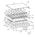
- FIG. 1 is an exploded perspective view of a battery pack 10 according to one embodiment.
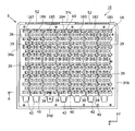
- FIG. 2 is a top view of the battery pack with the top plate removed.
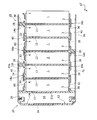
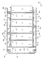
- 3 is a cross-sectional view taken along the line AA in FIG.
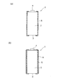
- FIG. 4 is a diagram illustrating a battery cell used in the embodiment.
- the battery pack 10 includes a large number of battery cells 1, a lower holding member 12 for arranging the battery cells 1 in an aligned manner, and an upper holding member 14 provided so as to cover the upper part of the battery cell 1.
- a negative electrode current collector plate (second current collector plate) 16 electrically connected to the negative electrode terminal (second side terminal) of the battery cell 1, and a positive electrode connected to the positive electrode terminal (one side terminal) of the battery cell 1.
- Current collector plate (first current collector plate) 18, these battery cells 1, lower holding member 12, upper holding member 14, negative electrode current collector plate (second current collecting plate) 16, lower holding member 12, And a holding portion 20 including the upper holding member 14.
- the arrow Z direction indicates the vertical direction
- the arrow X indicates the width direction
- the arrow Y shows the front-back direction orthogonal to the width direction on a horizontal surface, and in embodiment, the arrow Y has shown the direction which goes back from the front in FIG.
- the battery cell 1 is a chargeable / dischargeable secondary battery made of, for example, a cylindrical lithium ion battery. As shown in FIG. 4A, the battery cell 1 has a cylindrical body portion 2, a negative electrode terminal 3 provided on one end side of the body portion 2, and a convex shape on the other end side of the body portion 2. And a positive electrode terminal 4 provided.
- An insulating sheet 5 made of, for example, a resin film is attached to the body 2 of the battery cell 1. The end portion of the insulating sheet 5 is attached in a bent state to the peripheral edge portion of the upper end surface of the body portion 2 including the positive electrode terminal 4.
- the current collector plate is short-circuited between the positive electrode terminal 4 having a convex shape and the body end surface that is a portion electrically connected to the negative electrode terminal 3. Can be prevented or suppressed.
- the insulating sheet 5 can be mounted around the battery cell 1 by fitting and heat shrinking a cylindrical heat-shrinkable film, for example.
- the battery cell 1 may be one in which a metal sleeve 6 is further attached to the outside of the insulating sheet 5 without a gap.
- the metal sleeve 6 can be mounted, for example, by press-fitting the battery cell 1 on which the insulating sheet 5 is mounted.
- the metal sleeve 6 may be mounted by winding a highly malleable rectangular metal plate along the body 2 of the battery cell 1. In this case, a portion where the metal plates wound around the body portion 2 of the battery cell 1 are in contact with each other is provided, and a portion where the metal plates are in contact with each other is welded to form the metal sleeve 6.
- the metal sleeve 6 is attached to the body 2 of the battery cell 1 via the insulating sheet 5 as described above, the body 2 is broken and gas is ejected when the inside of the battery cell 1 is at a high pressure, as will be described later. As a result, gas can surely be ejected from the terminal side on which a safety valve mechanism (not shown) is provided.
- a safety valve mechanism that ejects gas when the inside of the battery cell becomes high pressure is provided in the vicinity of the positive electrode terminal 4.
- the battery pack 10 of the embodiment includes a large number of battery cells 1. Specifically, as is apparent from the number of electrode portions 60 shown in FIG. 2, 312 battery cells 1 are included. In the embodiment, as will be described later, six battery blocks b1 to b6 each including 48 battery cells and one battery block including 24 battery cells 1 are provided in accordance with each divided current collector plate. b7. However, the arrangement of the battery cells 1 is not separated or partitioned between the battery blocks b1 to b7, but is separated by an electrical connection relationship by a current collector plate described later. Note that the number of battery cells 1 and the number of battery blocks included in the battery pack 10 can be appropriately changed according to the specifications of the battery pack.
- the lower holding member 12 is a holder member that holds the lower part of each battery cell 1 so that a large number of battery cells 1 are arranged and arranged.
- the lower holding member 12 for example, one integrally molded with a resin that is an insulating material can be used. Further, as shown in FIGS. 2 and 3, the lower holding member 12 is provided with a cylindrical storage portion in a staggered arrangement. Thus, by storing and holding the lower part of the battery cell 1 in the storage part of the lower holding member 12, a large number of battery cells 1 are arranged in a staggered manner.
- a lower opening 30 having a smaller diameter than the battery cell 1 is formed at the bottom of each storage portion of the lower holding member 12. Thereby, the negative electrode terminal 3 of the battery cell 1 stored in the storage portion is exposed downward through the lower opening 30.
- the lower part of the battery storage part 13 is in contact with the upper part of each storage part of the lower holding member 12.
- the battery storage portion 13 is a holder member that stores and holds the intermediate portion of each battery cell 1.
- the battery housing portion 13 may be formed integrally with a resin that is an insulating material.
- the battery storage unit 13 is provided with a cylindrical storage unit in a staggered arrangement.
- the upper holding member 14 is a holder member provided so as to hold the upper portions of the battery cells 1 arranged in a staggered manner by the lower holding member 12.
- the upper holding member 14 for example, a member formed integrally with a resin that is an insulating material can be used.
- the upper holding member 14 is also provided with a cylindrical storage portion similar to the lower holding member 12 in a staggered arrangement corresponding to each battery cell 1. Further, an upper opening 32 having a smaller diameter than the battery cell 1 is formed on the upper wall portion of the storage portion of the upper holding member 14. Thereby, the positive electrode terminal 4 of the battery cell 1 accommodated in the accommodating portion is exposed upward through the upper opening 32.
- the upper holding member 14 has side walls that hang downward from both side end portions in the width direction.
- the side wall is configured to be integrated with the side wall of the lower holding member 12 to form the side wall 34, and to form the lower gas flow path 50 between the side wall 22 a of the battery storage unit 13. .
- a concave portion 36 having a substantially rectangular shape in plan view is formed on the upper surface of the upper holding member 14, and the upper openings 32 described above are formed in a staggered arrangement.
- a plurality of partition walls 38 are erected in a recess 36 formed on the upper surface of the upper holding member 14. Specifically, in the embodiment, six partition walls 38 are formed to extend in the front-rear direction (arrow Y direction) at a position that becomes a boundary between the battery blocks b1 to b7.
- the partition wall 38 is formed in a wavy shape so as to follow the outer contour of the battery cell 1 located at the boundary between the battery blocks b1 to b7 in the battery cell 1 arranged in a staggered pattern.
- the concave portion 36 having a substantially rectangular shape as a whole is partitioned into seven strip-shaped concave portions 36 corresponding to the battery blocks b1 to b7 by the partition wall 38, and these strip-shaped concave portions 36 are respectively connected to the upper gas flow path. 40.
- Each upper gas flow path 40 is also formed to extend in the front-rear direction of the battery pack 10.
- a rear side wall surface 37 of the recess 36 is erected at the rear portion of the upper gas flow path 40.
- the top plate 24 described later is attached to the upper holding member 14 to close the upper portion of the upper gas flow path 40.
- the gas ejected from the battery cell 1 flows on the rear side of the upper gas flow path 40. It will be closed so that there is no.
- the upper holding member 14 is formed with a communication port 42 that communicates with each upper gas flow path 40 in the front portion (lower side in FIG. 2) of the battery pack 10.
- seven communication ports 42 having a substantially rectangular shape are formed corresponding to the upper gas flow paths 40.
- Each communication port 42 is a through hole for communicating the upper gas flow path 40 with a lower gas flow path 50 described later.
- the shape of the communication port 42 is not limited to a rectangular shape, and may be another shape such as a substantially triangular shape, a circular shape, or an elliptical shape.
- notches 39 are formed in the partition wall 38 at predetermined intervals.
- the upper gas flow paths 40 adjacent to each other in the width direction communicate with each other through the notch 39.
- the notch 39 is not at a position where the battery cells 1 face each other in the width direction at the boundary between the battery blocks b1 to b7, but the battery cells 1 sandwich the above boundary. In this case, it is preferable to form the partition wall portion corresponding to a position diagonally opposed to the width direction.
- a positive electrode current collector 18 is disposed at the bottom of the recess 36 formed in the upper holding member 14.
- the positive current collector 18 is also composed of positive current collectors 181 to 187 divided into seven in the width direction of the battery pack 10 corresponding to the battery blocks b1 to b7.
- the positive electrode current collector plate 18 is preferably composed of a thin conductive metal plate such as an aluminum plate, a copper plate, or a nickel plate.
- the edge portions of the divided positive electrode current collector plates 181 to 187 in the width direction follow the outline of the staggered battery cells 1 included in the respective battery blocks b1 to b7. It is formed in a wavy line shape. However, only the edge on one side in the width direction of the positive electrode current collector plate 187 corresponding to the seventh battery block b7 is formed in a straight line according to the side wall shape of the recess 36 of the upper holding member 14.
- the positive electrode current collector plates 181 to 187 divided corresponding to the respective battery blocks b1 to b7 have the edge shape as described above, so that the positive electrode current collector plates 181 to 187 are arranged in the band-shaped recess 36 formed on the upper surface of the upper holding member 14. When it is done, it is positioned by the wavy line-shaped partition wall 38 and the side wall surface of the recess 36. In this state, the positive electrode portions (first electrode portions) 60 formed in a staggered arrangement on the respective positive electrode current collecting plates 181 to 187 can contact the positive electrode terminals 4 of the battery cells 1 included in the respective battery blocks b1 to b7. Then, the electrode portion 60 is connected and fixed to the positive electrode terminal 4 by spot welding or the like. As a result, the positive terminals 4 of the battery cells 1 included in the battery blocks b1 to b7 are connected in parallel by the positive current collectors 181 to 187 corresponding to the battery blocks b1 to b7.
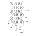
- FIG. 6 is an enlarged plan view showing the front end portion of the positive electrode current collector plate 181 corresponding to the first battery block b1.
- the positive electrode current collector plates 182 to 187 corresponding to the other second to sixth blocks b2 to b6 are completely or substantially the same as FIG.
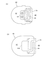
- FIG. 7A is an enlarged plan view of the electrode portion 60 formed on the positive electrode current collector plate 181.
- the electrode portion 60 formed on the positive electrode current collector plate 181 includes a substantially U-shaped cutout portion 62 formed by punching a thin metal plate.
- a terminal connection portion 64 connected to the positive electrode terminal 4 of the cell 1 is partitioned.
- a connecting terminal portion 19 is formed to extend from the front end edge portion of the positive electrode current collector plate 181.
- the connection terminal portion 19 is connected to the positive current collecting plates 182 to 187 of other battery blocks via bus bars, lead wires, substrates, etc. (not shown), so that all the battery blocks b1 to b1 included in the battery pack 10 are connected.
- the battery cells 1 of b7 are connected in parallel.
- the terminal connection portion 64 in the electrode portion 60 is connected to the substrate portion 68 of the positive electrode current collector plate 181 through a narrow and crank-shaped fuse 66.
- the fuse 66 is blown, whereby the battery cell 1 in which the abnormality has occurred can be electrically disconnected.
- the influence on other normal battery cells 1 included in the same battery block can be suppressed.
- an insulating resin film 70 having an appropriate rigidity is provided over the region including the fuse 66 and spans the terminal connection portion 64 and the substrate portion 68. You may affix by the method of welding etc. in the state. Thereby, since the narrow fuse 66 is reinforced by the resin film 70, it is possible to prevent the fuse 66 from being broken when the terminal connection portion 64 is bent or welded to the positive electrode terminal 4. .
- the terminal connection part 64 in the electrode part 60 may be bent so as to extend once in a direction perpendicular to the board part 68 and then in a direction parallel to the board part 68.
- the terminal connection portion 64 can be reliably brought into contact with the surface of the positive electrode terminal 4 located slightly below the bottom surface of the band-shaped recess 36 to be connected and fixed by welding or the like. it can.
- the electrode portion 60 is not limited to the configuration shown in FIG. 7A. As shown in FIG. 7B, the substrate portion 68 and the fuse 66 are arranged on the same plane without bending the terminal connection portion 64a. You may make it locate in. In this case, the upper holding member 14 may be formed so that the surface of the positive electrode terminal 4 of the battery cell 1 is flush with the bottom surface of the band-shaped recess 36.
- the direction of the electrode part 60 is not uniform. Specifically, when viewing the three electrode portions 60 corresponding to the three battery cells 1 positioned in the front row in the first battery block b1, the terminal connection portions 64 of the two right electrode portions 60 are in the same direction (see FIG. The terminal connection portion 64 of the remaining one electrode portion 60 is formed in the opposite direction (left side in the figure).
- the three electrode portions 60b corresponding to the three battery cells 1 in the second row from the front correspond to the three electrode portions 60a in the front row corresponding to the battery cells 1 arranged in a staggered manner.
- the battery cells 1 are arranged so as to be shifted in the left direction by a distance that is half the width direction pitch of the battery cell 1.
- the orientations of the terminal connection portions 64 in the three electrode portions 60b in the second row are the same in the left two electrode portions 60, but in the remaining one electrode portion 60, the orientation of the terminal connection portions 64 is in the opposite direction. Is formed.
- the direction of the terminal connection portion 64 extending from the substrate portion 68 via the fuse 66 is different without making the direction of the terminal connection portion 64 in the electrode portion 60 uniform. It is Thereby, the terminal connection part 64 whose dimension in the width direction (arrow X direction) is increased by forming the fuse 66 is provided at a position corresponding to the positive electrode terminals 4 of a large number of battery cells 1 arranged in a staggered manner in as small a space as possible. It becomes possible.
- the direction of the electrode part 60 in the positive electrode current collector plate 18 is not limited to this, and the terminal connection part 64 including the fuse 66 is provided when there is enough space due to the arrangement pitch of the battery cells 1 or the like. May be formed in the same direction.
- the electrode part 60 formed on the positive electrode current collector plate 18 is formed with the notch part 62 that defines the terminal connection part 64. Therefore, as shown in FIG. 3, when gas is ejected from the vicinity of the positive electrode terminal 4 of the battery cell 1, the gas passes through the upper opening 32 and the cutout portion 62 of the positive electrode current collector plate 18, and the upper gas flow path 40. It is possible to flow into.
- a negative electrode current collector plate 16 is disposed on the lower surface of the lower holding member 12.
- the negative electrode current collector plate 16 is also divided into seven, similar to the positive electrode current collector plate 18 described above.
- Each divided negative electrode current collector plate 16 is formed with electrode portions 61 corresponding to the negative electrode terminals 3 of the battery cells 1 arranged in a staggered manner.
- the electrode portion 61 is connected and fixed to the negative electrode terminal 3 of the battery cell 1 by spot welding or the like.
- the negative electrode current collector plate 16 may be formed with a fuse 66 similar to that of the positive electrode current collector plate 18.
- the positive electrode current collector plate 18 may not be formed with the fuse 66. That is, the fuse 66 may be formed on at least one of the positive electrode current collector plate 18 and the negative electrode current collector plate 16.
- the holding unit 20 includes side walls 34 a and 34 b provided on both sides in the width direction of the battery pack 10, and a rear wall 34 c connected to the rear end side of these side walls 34 a and 34 b,
- the front wall 34d attached to the front surface of the battery pack 10 and the top plate 24 and the bottom plate 26 that form the upper and lower surfaces of the battery pack 10 are configured.
- the holding part 20 forms an exterior case when assembled as the battery pack 10, and the side walls 34a, 34b, the rear wall 34c, and the front wall 34d correspond to side case parts.
- the side walls 34a and 34b and the rear wall 34c of the holding unit 20 are formed of a resin that is an insulating material.
- the front wall 34d of the holding portion 20 is configured as a resin molded product that is a separate part from the side walls 34a, 34b, the rear wall 34c, and the lower holding member 12.
- a connector insertion hole 23 for inserting an electrical connection connector is formed in the front wall 34d. Since the connector insertion hole 23 is in a state where the battery pack 10 is assembled and the connector is connected and closed, no gas is ejected from the inside of the battery pack 10 through the connector insertion hole 23.
- the top plate 24 and the bottom plate 26 constituting the holding unit 20 are preferably configured by metal plates. As shown in FIG. 3, a bent portion 25 that is bent downward is formed at the edge in the width direction of the top plate 24.
- the top plate 24 has the bent portion 25 fitted in the recesses of the side walls 34a and 34b of the upper holding member 14, and the edges of the top plate 24 are screwed on the side walls 34a and 34b and the rear wall 34c of the holding portion 20 with screws 28. It is fixed on the upper surface without any gaps. Further, the central region of the top plate 24 is fixed to the internal thread portion formed on the partition wall 38 of the upper holding member 14 with screws 28. Thereby, the top plate 24 is fixed to the upper surface of the upper holding member 14 without a gap.
- the bottom plate 26 is fixed to the lower surfaces of the side walls 34 a and 34 b and the rear wall 34 c of the holding unit 20 and the lower surface of the lower holding member 12 with screws 28, similarly to the top plate 24. Further, the front wall 34 d constituting the holding portion 20 is screwed and attached to the front edge portion of the top plate 24 and the front edge portion of the bottom plate 26.
- the battery cell 1, the lower holding member 12, the upper holding member 14, the negative current collector plate 16 and the positive current collector plate 18 are accommodated, and the top plate 24 and the bottom plate 26 are attached to the holding portion. 20 is assembled and the battery pack 10 is completed. At this time, a space is formed between the inner wall surface of the holding portion 20 and the aligned battery cells 1, and this space serves as the lower gas flow path 50.
- the lower gas flow path 50 is formed around a large number of battery cells 1 arranged in alignment inside the holding part 20.
- the lower gas flow path 50 is formed between the front wall 34d and the battery cell 1 or a substrate electrically connected to the battery cell 1 at the front portion of the battery pack 10 and is formed in the upper holding member 14.
- the upper gas flow path 40 communicates with the communication port 42.
- the lower gas flow path 50 on the side in the width direction of the battery pack 10 is between the side wall 34 a of the holding unit 20 and the side wall 22 a of the battery storage unit 13, and the side wall of the holding unit 20. 34 b and the side wall portion 22 b of the battery storage portion 13, and is connected from the front portion of the battery pack 10 to the side portion.
- the lower gas flow path 50 is connected to an exhaust port 52 formed on the upper surface of the rear wall 34c of the holding unit 20 at the rear part of the battery pack 10. Note that the lower gas flow path 50 does not have to be continuously formed over the entire circumference in the holding part 20 of the battery pack 10, and is connected by a path from the front part to the exhaust port 52 via the side part. That's fine.
- the gas passes through the upper opening 32 of the upper holding member 14 and the notch 62 of the positive current collector 18.
- the upper gas flow path 40 Since the upper gas flow path 40 is closed by the rear side wall surface 37 of the recess 36 on the rear side of the battery pack 10, the upper gas flow path 40 cannot flow rearward, and moves toward the communication port 42 located at the front portion of the battery pack 10. It is guided and flows.
- the high-temperature gas passes through the notch 39 formed in the partition wall 38, and the upper gas channel 40 adjacent through the notch 39 from the upper gas channel 40 corresponding to the ejected battery cell 1. Can also flow into. Thus, it is effective to lower the gas temperature by expanding the flow direction of the high temperature gas in a plane.
- the hot gas that has flowed forward through the upper gas channel 40 flows into the lower gas channel 50 through the communication port 42 of the upper holding member 14. Then, the gas travels along the lower gas flow path 50 from the front part of the battery pack 10 to the rear part around the side in the width direction, and exhausts to the outside of the battery pack 10 through the exhaust port 52 from there. Is done.
- the high temperature gas ejected from the battery cell 1 is once guided forward and then flowed to the lower gas flow path, and from there to the exhaust port provided at the rear part of the battery pack.
- the battery pack 10 is exhausted backward.
- the temperature of the gas ejected from the battery cell 1 can be lowered to a level that does not affect the outside of the battery pack, and the safety of the battery pack.
- the top plate 24 and the bottom plate 26 are fixed to the upper and lower surfaces of the lower holding member 12 and the upper holding member 14 without any gaps, the high-temperature gas ejected from the battery cell 1 into the upper gas flow path 40 is Before the temperature is sufficiently lowered, it can be prevented that the top plate 24 and the bottom plate 26 and the side wall portions 22a, 22b, the rear wall portion 22c, and the front wall portion 22d of the battery storage portion 13 are ejected to the outside.
- the strength of the holding portion 20 is sufficiently ensured when the battery pack 10 is stacked and installed in the vertical direction. can do.
- the exhaust port 52 is provided on the rear wall 34c of the holding part 20 of the battery pack 10.
- the present invention is not limited to this, and the side walls 34a and 34b of the holding part 20 of the battery pack 10 are not limited thereto. It may be provided so as to exhaust in the width direction.
- the safety valve mechanism is provided on the positive electrode terminal 4 side of the battery cell 1.
- the embodiment can also be applied to the case where the safety valve mechanism is provided on the negative electrode terminal 3 of the battery cell 1.
- the negative electrode terminal 3 may be arranged upward, or as shown in FIG. 3, the orientation of the battery cell 1 is left as it is, and the gap between the lower holding member 12 and the bottom plate 26 is maintained. What is necessary is just to comprise so that space may communicate with the lower gas flow path 50 in the front part of the battery pack 10.
- the present invention is not limited to this.
- the lower holding member The lower gas channel 41 may be formed between the upper plate 12 and the bottom plate 26 in the same manner as the upper gas channel 40.
- a lower partition wall 12a extending upward from the lower holding member 12 and an upper partition wall 14a extending downward from the upper holding member 14 may be disposed between the battery cells 1 in which the directions of the positive electrodes 4 are different.
- the connection terminal portions 19 projecting from the current collector plates 16a and 18a are used for voltage detection for monitoring the voltages of the plurality of battery cells 1 connected between the current collector plates 16a and 18a. It can be used as a terminal.
- the positive terminal 4 and the negative terminal 3 facing upward correspond to “one side terminal”
- the negative terminal 4 and the positive terminal facing downward correspond to “other side terminal”.
Landscapes
- Chemical & Material Sciences (AREA)
- Chemical Kinetics & Catalysis (AREA)
- Electrochemistry (AREA)
- General Chemical & Material Sciences (AREA)
- Inorganic Chemistry (AREA)
- Battery Mounting, Suspending (AREA)
- Sealing Battery Cases Or Jackets (AREA)
- Connection Of Batteries Or Terminals (AREA)
- Engineering & Computer Science (AREA)
- Materials Engineering (AREA)
- Manufacturing & Machinery (AREA)
Abstract
Description
この場合、電池セル1の胴部2に巻いた金属板同士が接する部分を設けて、金属板同士が接する部分を溶接して金属スリーブ6を形成する。このように電池セル1の胴部2に絶縁シート5を介して金属スリーブ6を装着すれば、後述するように電池セル1の内部が高圧になったとき胴部2が破れてガスが噴出するのを防止でき、その結果、図示しない安全弁機構が設けられた側の端子側からガスが確実に噴出させることができる。実施形態では、電池セル内部が高圧になったときにガスを噴出させる安全弁機構が、正極端子4付近に設けられているものとして以下の説明を続ける。
連通口42の形状は、矩形状に限定されるものではなく、略三角状、円形状、楕円状等の他の形状であってもよい。
具体的には、第1電池ブロックb1において最前列に位置する3本の電池セル1に対応する3つの電極部60について見ると、右側2つの電極部60の端子接続部64が同じ方向(図中の右側)に向いて形成されているのに対し、残る1つの電極部60における端子接続部64は反対方向(図中の左側)に向いて形成されている。
負極集電板16もまた、上記の正極集電板18と同様に7つに分割されている。分割された各負極集電板16には、千鳥配置された電池セル1の負極端子3に対応して電極部61が形成されている。この電極部61がスポット溶接等によって電池セル1の負極端子3に接続固定されている。なお、負極集電板16には、正極集電板18と同様のヒューズ66が形成されていてもよい。負極集電板16にヒューズ66がある場合、正極集電板18にはヒューズ66を形成しなくてもよい。すなわち、正極集電板18もしくは負極集電板16の少なくともどちらかにヒューズ66が形成されていればよい。
図3に示すように、天板24の幅方向の縁部には下方に折り曲げられた折曲部25が形成されている。天板24は、折曲部25を上側保持部材14の側壁34a,34bの凹部にはめ込んだ状態で、天板24の縁部をねじ28によって保持部20の側壁34a,34bおよび後壁34cの上面に隙間無く固定される。また、天板24の中央領域は、上側保持部材14の仕切壁38に形成された雌ねじ部にねじ28によって固定される。これにより、天板24は、上側保持部材14の上面に対しても隙間なく固定される。
切欠部、64,64a 端子接続部、66 ヒューズ、68 基板部、70 樹脂フィルム、 正極集電板、b1~b7 電池ブロック、X 幅方向、Y 前後方向、Z 上下方向。
Claims (7)
- 多数の電池セルと、
整列配置された筒状の電池収納部に前記電池セルを保持する保持部と、
前記保持部は、
前記電池セルの下部をそれぞれ収容した状態で保持するように設けられ、下側開口部が形成されている下側保持部材と、
前記下側保持部材によって整列配置された多数の電池セルの上部を保持するように設けられ、上側開口部が形成されている上側保持部材とを有し、
前記電池セルの上部にそれぞれ電気的に接続される第1電極部が前記各電池セルに対応して形成されている第1集電板、および、前記電池セルの下部にそれぞれ電気的に接続される第2電極部が前記各電池セルに対応して形成されている第2集電板と、
前記電池セル、前記第1集電部材を収納する前記上側保持部材、ならびに、前記第2集電部材を収納する前記下側保持部材と、を備える電池パックであって、
前記保持部には前記電池セルから噴出したガスを前記保持部内で第1方向へ誘導する第1ガス流路が形成され、前記保持部の内部には整列配置された多数の電池セルの周囲に第2ガス流路が形成されるとともに前記保持部には前記第1方向と異なる第2方向に前記ガスを排気する排気口が形成されており、保持部には第1ガス流路と第2ガス流路に連通させる連通口が設けられている、
電池パック。 - 請求項1に記載の電池パックにおいて、前記第1ガス流路は、前記上側保持部材に形成され、前記第2ガス流路は、前記下側保持部材の内部の整列配置された多数の電池セルの周囲に形成され、前記排気口は、前記上側保持部材に形成されている、電池パック。
- 請求項1または2に記載の電池パックにおいて、前記第1ガス流路は、前記下側保持部材に形成され、前記第2ガス流路は、前記上側保持部材の内部の整列配置された多数の電池セルの周囲に形成され、前記排気口は、前記下側保持部材に形成されている、電池パック。
- 請求項1~3に記載の電池パックにおいて、
前記多数の電池セルは複数の電池ブロックに分かれており、前記第1集電板および前記第2集電板は前記各電池ブロックに含まれる電池セルを並列接続するようにそれぞれ複数に分割されており、前記上側保持部材には前記複数の第2集電板の間を仕切る複数の仕切壁が設けられ、これらの仕切壁によって前記上部ガス流路が各電池ブロックに対応して複数に分割されている、電池パック。 - 請求項4に記載の電池パックにおいて、
前記仕切壁には切欠部が形成されており、前記仕切壁によって複数に区画された前記上部ガス流路が前記切欠部を介して互いに連通する、電池パック。 - 請求項1~5のいずれか一項に記載の電池パックにおいて、
前記下側保持部材は、四方周囲を取り囲む樹脂製の側面ケース部と、該側面ケース部の上部および下部に取り付けられる金属製の天板および底板とにより構成され、前記天板は前記上部ガス流路を形成する前記上側保持部材の上面および前記側面ケース部の上面に隙間なく固定される、電池パック。 - 請求項1~6のいずれか一項に記載の電池パックにおいて、
前記電池セルは、筒状の胴部と、該胴部の両側端部に前記一方側端子および他方側端子を備え、前記胴部に周囲には絶縁シートが装着されるとともに該絶縁シートの外側に金属製のスリーブが装着されている、電池パック。
Priority Applications (2)
| Application Number | Priority Date | Filing Date | Title |
|---|---|---|---|
| US14/778,586 US9985259B2 (en) | 2013-03-29 | 2014-03-10 | Battery pack |
| JP2015508014A JP6109926B2 (ja) | 2013-03-29 | 2014-03-10 | 電池パック |
Applications Claiming Priority (2)
| Application Number | Priority Date | Filing Date | Title |
|---|---|---|---|
| JP2013-072664 | 2013-03-29 | ||
| JP2013072664 | 2013-03-29 |
Publications (1)
| Publication Number | Publication Date |
|---|---|
| WO2014156001A1 true WO2014156001A1 (ja) | 2014-10-02 |
Family
ID=51623022
Family Applications (1)
| Application Number | Title | Priority Date | Filing Date |
|---|---|---|---|
| PCT/JP2014/001313 Ceased WO2014156001A1 (ja) | 2013-03-29 | 2014-03-10 | 電池パック |
Country Status (3)
| Country | Link |
|---|---|
| US (1) | US9985259B2 (ja) |
| JP (1) | JP6109926B2 (ja) |
| WO (1) | WO2014156001A1 (ja) |
Cited By (27)
| Publication number | Priority date | Publication date | Assignee | Title |
|---|---|---|---|---|
| JP2016081793A (ja) * | 2014-10-20 | 2016-05-16 | トヨタ自動車株式会社 | 蓄電モジュール |
| JP2017033721A (ja) * | 2015-07-30 | 2017-02-09 | 株式会社Gsユアサ | 蓄電装置 |
| WO2017169524A1 (ja) * | 2016-03-30 | 2017-10-05 | 三洋電機株式会社 | 電池パック |
| JP2017204525A (ja) * | 2016-05-10 | 2017-11-16 | 住友電工プリントサーキット株式会社 | フレキシブルプリント配線板及び電子部品 |
| JP2017212065A (ja) * | 2016-05-24 | 2017-11-30 | トヨタ自動車株式会社 | 車載用電池モジュール |
| KR20180055671A (ko) * | 2016-11-08 | 2018-05-25 | 스톤 에너지 테크놀로지 코포레이션 | 무용접 원통형 배터리 팩 장치 |
| US20180233723A1 (en) * | 2017-02-10 | 2018-08-16 | Toyota Jidosha Kabushiki Kaisha | Battery module and battery pack |
| JP2018537834A (ja) * | 2016-06-09 | 2018-12-20 | エルジー・ケム・リミテッド | 二次電池 |
| WO2019044378A1 (ja) * | 2017-08-29 | 2019-03-07 | 三洋電機株式会社 | 電池パックとその製造方法 |
| WO2020152992A1 (ja) * | 2019-01-25 | 2020-07-30 | 三洋電機株式会社 | パック電池 |
| CN111584791A (zh) * | 2020-06-22 | 2020-08-25 | 昆山宝创新能源科技有限公司 | 电池模组 |
| JP2020532062A (ja) * | 2018-05-03 | 2020-11-05 | エルジー・ケム・リミテッド | バッテリーモジュール及びこれを含むバッテリーパック |
| JPWO2021019970A1 (ja) * | 2019-07-29 | 2021-02-04 | ||
| US10916744B2 (en) | 2016-06-29 | 2021-02-09 | Panasonic Intellectual Property Management Co., Ltd. | Battery block |
| JP2021022545A (ja) * | 2019-07-30 | 2021-02-18 | 三洋電機株式会社 | 電源装置 |
| JP2021022544A (ja) * | 2019-07-30 | 2021-02-18 | 三洋電機株式会社 | 電源装置 |
| JP2021519501A (ja) * | 2018-04-06 | 2021-08-10 | シーピーエス テクノロジー ホールディングス エルエルシーCPS Technology Holdings LLC | 電池モジュールのための熱管理システム、電池システム |
| JP2022518696A (ja) * | 2019-01-29 | 2022-03-16 | ナラバンダ テクノロジー ホールディングス ピーティーワイ リミテッド | バッテリーパック、バッテリーアセンブリ、バッテリーパックの形成方法、バッテリーアセンブリの形成方法、及び、バッテリーパック用エンドプレート |
| US11462799B2 (en) | 2018-01-15 | 2022-10-04 | Lg Energy Solution, Ltd. | Battery module having gas discharge structure |
| WO2022209866A1 (ja) * | 2021-03-31 | 2022-10-06 | 株式会社村田製作所 | 蓄電装置、電動工具および電動車両 |
| JP2023519469A (ja) * | 2019-12-03 | 2023-05-11 | サイック・モーター・コーポレーション・リミテッド | 電池モジュール、電池パックおよび電池エネルギー貯蔵装置 |
| JP2023067618A (ja) * | 2021-11-01 | 2023-05-16 | 株式会社Gsユアサ | 蓄電装置 |
| JPWO2023120437A1 (ja) * | 2021-12-24 | 2023-06-29 | ||
| JP2025508493A (ja) * | 2022-10-14 | 2025-03-26 | 寧徳時代新能源科技股▲分▼有限公司 | 電池及び電力消費装置 |
| JP2025157542A (ja) * | 2024-09-09 | 2025-10-15 | 深▲セン▼市華宝新能源股▲フン▼有限公司 | ハウジングアセンブリ、電池パック及び蓄電電源 |
| JP2026507598A (ja) * | 2023-09-11 | 2026-03-04 | エルジー エナジー ソリューション リミテッド | バッテリーパック |
| WO2026063040A1 (ja) * | 2024-09-18 | 2026-03-26 | トヨタ自動車株式会社 | 蓄電装置 |
Families Citing this family (26)
| Publication number | Priority date | Publication date | Assignee | Title |
|---|---|---|---|---|
| DE102016118753A1 (de) * | 2016-10-04 | 2018-04-05 | Johnson Controls Advanced Power Solutions Gmbh | Energiespeichersystem |
| KR102246768B1 (ko) * | 2016-12-09 | 2021-04-30 | 삼성에스디아이 주식회사 | 배터리 팩 |
| CN106876644A (zh) * | 2017-03-30 | 2017-06-20 | 深圳市沃特玛电池有限公司 | 一种电连接板 |
| KR102505612B1 (ko) | 2018-01-31 | 2023-03-03 | 삼성에스디아이 주식회사 | 배터리 팩 |
| KR102330378B1 (ko) * | 2018-04-20 | 2021-11-22 | 주식회사 엘지에너지솔루션 | 디개싱 유로를 구비한 배터리 팩 |
| WO2020003800A1 (ja) | 2018-06-26 | 2020-01-02 | 三洋電機株式会社 | 電源装置及びこれを備える車両 |
| WO2020039722A1 (ja) * | 2018-08-23 | 2020-02-27 | パナソニックIpマネジメント株式会社 | 電池モジュール |
| US20200067157A1 (en) * | 2018-08-27 | 2020-02-27 | Electric Power Systems, LLC | Hybrid cooling for battery pack |
| US20200091493A1 (en) * | 2018-09-19 | 2020-03-19 | Tiveni Mergeco, Inc. | Battery module including coated or clad material contact plate |
| JP7292812B2 (ja) * | 2019-01-25 | 2023-06-19 | パナソニックエナジー株式会社 | パック電池 |
| WO2020164692A1 (de) * | 2019-02-12 | 2020-08-20 | Hpf Gmbh | Akkumulatormodul und energiespeicher |
| JP7576537B2 (ja) * | 2019-03-27 | 2024-10-31 | パナソニックエナジー株式会社 | 電源装置 |
| KR102820678B1 (ko) | 2019-09-24 | 2025-06-12 | 주식회사 엘지에너지솔루션 | 버스바 플레이트를 포함하는 배터리 모듈, 그것을 포함하는 배터리 팩, 및 전자 디바이스 |
| CN114128033B (zh) | 2019-10-11 | 2024-06-28 | 株式会社Lg新能源 | 包括汇流条板的电池模块、包括电池模块的电池组及电子装置 |
| KR102913987B1 (ko) * | 2019-10-18 | 2026-01-15 | 주식회사 엘지에너지솔루션 | 전지 모듈 및 이을 포함하는 전지 팩 |
| CN113809479B (zh) * | 2020-05-27 | 2023-02-10 | 比亚迪股份有限公司 | 电池包以及车辆 |
| CN111952504A (zh) * | 2020-08-20 | 2020-11-17 | 华霆(合肥)动力技术有限公司 | 电池模组和电源装置 |
| JP7528253B2 (ja) * | 2020-09-21 | 2024-08-05 | エルジー エナジー ソリューション リミテッド | バッテリーモジュール、バッテリーパック及びそれを含む自動車 |
| CN112467299B (zh) * | 2020-11-27 | 2025-11-21 | 福建飞毛腿动力科技有限公司 | 一种电池组泄压风道结构 |
| KR102708662B1 (ko) * | 2020-12-07 | 2024-09-20 | 주식회사 엘지에너지솔루션 | 배터리 모듈, 배터리 팩, 및 자동차 |
| CN112713437A (zh) * | 2020-12-14 | 2021-04-27 | 系统电子科技(镇江)有限公司 | 一种电池安全连接件 |
| WO2022139640A1 (en) * | 2020-12-22 | 2022-06-30 | Johansson Olsson Technique & Design Ab | Battery assembly |
| US20220263181A1 (en) * | 2021-02-17 | 2022-08-18 | Ematrix Energy Systems, Inc. | Expandable battery module |
| US20240120604A1 (en) * | 2021-02-26 | 2024-04-11 | Panasonic Energy Co.,Ltd. | Power supply device |
| CN121002717A (zh) * | 2023-09-08 | 2025-11-21 | Sk新能源株式会社 | 电池组件 |
| FR3153472A1 (fr) | 2023-09-27 | 2025-03-28 | Saft | Module de batterie et système de stockage de puissance électrique associé |
Citations (2)
| Publication number | Priority date | Publication date | Assignee | Title |
|---|---|---|---|---|
| JP2011070872A (ja) * | 2009-09-25 | 2011-04-07 | Panasonic Corp | 電池モジュール |
| WO2012081137A1 (ja) * | 2010-12-13 | 2012-06-21 | パナソニック株式会社 | 電池パック |
Family Cites Families (10)
| Publication number | Priority date | Publication date | Assignee | Title |
|---|---|---|---|---|
| US6187470B1 (en) * | 1997-06-10 | 2001-02-13 | Roland K. Peterson | Solderless battery cell holder |
| JP3777748B2 (ja) * | 1997-09-30 | 2006-05-24 | 株式会社ジーエス・ユアサコーポレーション | 組電池 |
| JP4431412B2 (ja) * | 2004-01-23 | 2010-03-17 | Fdkエナジー株式会社 | 電池収納ケース |
| JP2010146774A (ja) | 2008-12-16 | 2010-07-01 | Sanyo Electric Co Ltd | 電池パック |
| WO2011007535A1 (ja) * | 2009-07-17 | 2011-01-20 | パナソニック株式会社 | 電池接続部材とそれを用いた電池モジュール |
| JP5466906B2 (ja) * | 2009-09-18 | 2014-04-09 | パナソニック株式会社 | 電池モジュール |
| US8291567B1 (en) * | 2010-08-25 | 2012-10-23 | The United States Of America As Represented By The Secretary Of The Navy | Method for maximizing packing density with cylindrical objects in cylindrical cavities |
| US20130011719A1 (en) * | 2011-01-25 | 2013-01-10 | Panasonic Corporation | Battery module and battery assembly used therein |
| EP2738835B1 (en) * | 2011-07-29 | 2016-04-13 | Panasonic Intellectual Property Management Co., Ltd. | Battery module |
| US20140178723A1 (en) * | 2011-08-10 | 2014-06-26 | Panasonic Corporation | Battery block and battery module comprising same |
-
2014
- 2014-03-10 US US14/778,586 patent/US9985259B2/en active Active
- 2014-03-10 JP JP2015508014A patent/JP6109926B2/ja active Active
- 2014-03-10 WO PCT/JP2014/001313 patent/WO2014156001A1/ja not_active Ceased
Patent Citations (2)
| Publication number | Priority date | Publication date | Assignee | Title |
|---|---|---|---|---|
| JP2011070872A (ja) * | 2009-09-25 | 2011-04-07 | Panasonic Corp | 電池モジュール |
| WO2012081137A1 (ja) * | 2010-12-13 | 2012-06-21 | パナソニック株式会社 | 電池パック |
Cited By (46)
| Publication number | Priority date | Publication date | Assignee | Title |
|---|---|---|---|---|
| JP2016081793A (ja) * | 2014-10-20 | 2016-05-16 | トヨタ自動車株式会社 | 蓄電モジュール |
| JP2017033721A (ja) * | 2015-07-30 | 2017-02-09 | 株式会社Gsユアサ | 蓄電装置 |
| WO2017169524A1 (ja) * | 2016-03-30 | 2017-10-05 | 三洋電機株式会社 | 電池パック |
| JP2017204525A (ja) * | 2016-05-10 | 2017-11-16 | 住友電工プリントサーキット株式会社 | フレキシブルプリント配線板及び電子部品 |
| JP2017212065A (ja) * | 2016-05-24 | 2017-11-30 | トヨタ自動車株式会社 | 車載用電池モジュール |
| JP2018537834A (ja) * | 2016-06-09 | 2018-12-20 | エルジー・ケム・リミテッド | 二次電池 |
| US11398659B2 (en) | 2016-06-29 | 2022-07-26 | Panasonic Intellectual Property Management Co., Ltd. | Battery block |
| US10916744B2 (en) | 2016-06-29 | 2021-02-09 | Panasonic Intellectual Property Management Co., Ltd. | Battery block |
| KR20180055671A (ko) * | 2016-11-08 | 2018-05-25 | 스톤 에너지 테크놀로지 코포레이션 | 무용접 원통형 배터리 팩 장치 |
| KR101962858B1 (ko) | 2016-11-08 | 2019-03-27 | 스톤 에너지 테크놀로지 코포레이션 | 무용접 원통형 배터리 팩 장치 |
| US20180233723A1 (en) * | 2017-02-10 | 2018-08-16 | Toyota Jidosha Kabushiki Kaisha | Battery module and battery pack |
| US11005138B2 (en) * | 2017-02-10 | 2021-05-11 | Toyota Jidosha Kabushiki Kaisha | Battery module and battery pack |
| JPWO2019044378A1 (ja) * | 2017-08-29 | 2020-10-01 | 三洋電機株式会社 | 電池パックとその製造方法 |
| JP7139338B2 (ja) | 2017-08-29 | 2022-09-20 | 三洋電機株式会社 | 電池パックとその製造方法 |
| WO2019044378A1 (ja) * | 2017-08-29 | 2019-03-07 | 三洋電機株式会社 | 電池パックとその製造方法 |
| US11462799B2 (en) | 2018-01-15 | 2022-10-04 | Lg Energy Solution, Ltd. | Battery module having gas discharge structure |
| JP7088607B2 (ja) | 2018-04-06 | 2022-06-21 | シーピーエス テクノロジー ホールディングス エルエルシー | 電池モジュールのための熱管理システム、電池システム |
| JP2021519501A (ja) * | 2018-04-06 | 2021-08-10 | シーピーエス テクノロジー ホールディングス エルエルシーCPS Technology Holdings LLC | 電池モジュールのための熱管理システム、電池システム |
| JP2020532062A (ja) * | 2018-05-03 | 2020-11-05 | エルジー・ケム・リミテッド | バッテリーモジュール及びこれを含むバッテリーパック |
| JP7401467B2 (ja) | 2019-01-25 | 2023-12-19 | パナソニックエナジー株式会社 | パック電池 |
| WO2020152992A1 (ja) * | 2019-01-25 | 2020-07-30 | 三洋電機株式会社 | パック電池 |
| JPWO2020152992A1 (ja) * | 2019-01-25 | 2021-11-25 | 三洋電機株式会社 | パック電池 |
| JP7553961B2 (ja) | 2019-01-29 | 2024-09-19 | ナラバンダ テクノロジー ホールディングス ピーティーワイ リミテッド | バッテリーパック、バッテリーアセンブリ、バッテリーパックの形成方法、バッテリーアセンブリの形成方法、及び、バッテリーパック用エンドプレート |
| JP2022518696A (ja) * | 2019-01-29 | 2022-03-16 | ナラバンダ テクノロジー ホールディングス ピーティーワイ リミテッド | バッテリーパック、バッテリーアセンブリ、バッテリーパックの形成方法、バッテリーアセンブリの形成方法、及び、バッテリーパック用エンドプレート |
| CN114080718B (zh) * | 2019-07-29 | 2023-08-25 | 松下新能源株式会社 | 电池组 |
| WO2021019970A1 (ja) * | 2019-07-29 | 2021-02-04 | 三洋電機株式会社 | 電池パック |
| US12300842B2 (en) | 2019-07-29 | 2025-05-13 | Panasonic Energy Co., Ltd. | Battery pack |
| JP7621257B2 (ja) | 2019-07-29 | 2025-01-24 | パナソニックエナジー株式会社 | 電池パック |
| CN114080718A (zh) * | 2019-07-29 | 2022-02-22 | 三洋电机株式会社 | 电池组 |
| JPWO2021019970A1 (ja) * | 2019-07-29 | 2021-02-04 | ||
| JP7461723B2 (ja) | 2019-07-30 | 2024-04-04 | パナソニックエナジー株式会社 | 電源装置 |
| JP7461722B2 (ja) | 2019-07-30 | 2024-04-04 | パナソニックエナジー株式会社 | 電源装置 |
| JP2021022544A (ja) * | 2019-07-30 | 2021-02-18 | 三洋電機株式会社 | 電源装置 |
| JP2021022545A (ja) * | 2019-07-30 | 2021-02-18 | 三洋電機株式会社 | 電源装置 |
| JP2023519469A (ja) * | 2019-12-03 | 2023-05-11 | サイック・モーター・コーポレーション・リミテッド | 電池モジュール、電池パックおよび電池エネルギー貯蔵装置 |
| JP7326620B2 (ja) | 2019-12-03 | 2023-08-15 | サイック・モーター・コーポレーション・リミテッド | 電池モジュール、電池パックおよび電池エネルギー貯蔵装置 |
| CN111584791A (zh) * | 2020-06-22 | 2020-08-25 | 昆山宝创新能源科技有限公司 | 电池模组 |
| WO2022209866A1 (ja) * | 2021-03-31 | 2022-10-06 | 株式会社村田製作所 | 蓄電装置、電動工具および電動車両 |
| JP2023067618A (ja) * | 2021-11-01 | 2023-05-16 | 株式会社Gsユアサ | 蓄電装置 |
| JP7834986B2 (ja) | 2021-11-01 | 2026-03-25 | 株式会社Gsユアサ | 蓄電装置 |
| JPWO2023120437A1 (ja) * | 2021-12-24 | 2023-06-29 | ||
| JP2025508493A (ja) * | 2022-10-14 | 2025-03-26 | 寧徳時代新能源科技股▲分▼有限公司 | 電池及び電力消費装置 |
| JP7806281B2 (ja) | 2022-10-14 | 2026-01-26 | 寧徳時代新能源科技股▲分▼有限公司 | 電池及び電力消費装置 |
| JP2026507598A (ja) * | 2023-09-11 | 2026-03-04 | エルジー エナジー ソリューション リミテッド | バッテリーパック |
| JP2025157542A (ja) * | 2024-09-09 | 2025-10-15 | 深▲セン▼市華宝新能源股▲フン▼有限公司 | ハウジングアセンブリ、電池パック及び蓄電電源 |
| WO2026063040A1 (ja) * | 2024-09-18 | 2026-03-26 | トヨタ自動車株式会社 | 蓄電装置 |
Also Published As
| Publication number | Publication date |
|---|---|
| US20160141573A1 (en) | 2016-05-19 |
| US9985259B2 (en) | 2018-05-29 |
| JPWO2014156001A1 (ja) | 2017-02-16 |
| JP6109926B2 (ja) | 2017-04-05 |
Similar Documents
| Publication | Publication Date | Title |
|---|---|---|
| JP6109926B2 (ja) | 電池パック | |
| JP7186371B2 (ja) | 電池ブロック | |
| US10211434B2 (en) | Battery pack | |
| CN101771163B (zh) | 二次电池模块 | |
| JP4665277B2 (ja) | バッテリ装置 | |
| JP4036805B2 (ja) | パック電池 | |
| CN107425161B (zh) | 电池盒 | |
| JP6283964B2 (ja) | 電池モジュール | |
| US20100124693A1 (en) | Secondary battery pack | |
| CN109328407B (zh) | 电池块以及电池模块 | |
| JP5606576B2 (ja) | 二次電池パック | |
| US20130252045A1 (en) | Battery module | |
| JP6296361B2 (ja) | 電池ユニット | |
| JPWO2017130259A1 (ja) | 電池パック | |
| TW201126791A (en) | Battery system with a plurality of batteries housed in an external case | |
| WO2012073399A1 (ja) | 電池モジュール及び電池パック | |
| JP6454423B2 (ja) | バッテリセル、及び、バッテリシステム | |
| JP6551177B2 (ja) | 電池ユニット | |
| TWM568503U (zh) | Battery module and power battery system | |
| JP4747576B2 (ja) | 組電池 | |
| KR20150107108A (ko) | 배터리팩 | |
| JP7147253B2 (ja) | 蓄電装置 | |
| US20250192358A1 (en) | Battery pack | |
| KR20150007727A (ko) | 셀 모듈 어셈블리의 모듈 하우징 | |
| JP2013115018A (ja) | 電池パック |
Legal Events
| Date | Code | Title | Description |
|---|---|---|---|
| 121 | Ep: the epo has been informed by wipo that ep was designated in this application |
Ref document number: 14774307 Country of ref document: EP Kind code of ref document: A1 |
|
| ENP | Entry into the national phase |
Ref document number: 2015508014 Country of ref document: JP Kind code of ref document: A |
|
| WWE | Wipo information: entry into national phase |
Ref document number: 14778586 Country of ref document: US |
|
| NENP | Non-entry into the national phase |
Ref country code: DE |
|
| 122 | Ep: pct application non-entry in european phase |
Ref document number: 14774307 Country of ref document: EP Kind code of ref document: A1 |