WO2014155835A1 - ベルト式無段変速機における軸支持構造 - Google Patents
ベルト式無段変速機における軸支持構造 Download PDFInfo
- Publication number
- WO2014155835A1 WO2014155835A1 PCT/JP2013/082542 JP2013082542W WO2014155835A1 WO 2014155835 A1 WO2014155835 A1 WO 2014155835A1 JP 2013082542 W JP2013082542 W JP 2013082542W WO 2014155835 A1 WO2014155835 A1 WO 2014155835A1
- Authority
- WO
- WIPO (PCT)
- Prior art keywords
- bearing
- belt
- torque cam
- shaft
- outer peripheral
- Prior art date
- Legal status (The legal status is an assumption and is not a legal conclusion. Google has not performed a legal analysis and makes no representation as to the accuracy of the status listed.)
- Ceased
Links
Images

Classifications
-
- F—MECHANICAL ENGINEERING; LIGHTING; HEATING; WEAPONS; BLASTING
- F16—ENGINEERING ELEMENTS AND UNITS; GENERAL MEASURES FOR PRODUCING AND MAINTAINING EFFECTIVE FUNCTIONING OF MACHINES OR INSTALLATIONS; THERMAL INSULATION IN GENERAL
- F16H—GEARING
- F16H37/00—Combinations of mechanical gearings, not provided for in groups F16H1/00 - F16H35/00
- F16H37/02—Combinations of mechanical gearings, not provided for in groups F16H1/00 - F16H35/00 comprising essentially only toothed or friction gearings
- F16H37/021—Combinations of mechanical gearings, not provided for in groups F16H1/00 - F16H35/00 comprising essentially only toothed or friction gearings toothed gearing combined with continuously variable friction gearing
- F16H37/022—Combinations of mechanical gearings, not provided for in groups F16H1/00 - F16H35/00 comprising essentially only toothed or friction gearings toothed gearing combined with continuously variable friction gearing the toothed gearing having orbital motion
-
- F—MECHANICAL ENGINEERING; LIGHTING; HEATING; WEAPONS; BLASTING
- F16—ENGINEERING ELEMENTS AND UNITS; GENERAL MEASURES FOR PRODUCING AND MAINTAINING EFFECTIVE FUNCTIONING OF MACHINES OR INSTALLATIONS; THERMAL INSULATION IN GENERAL
- F16H—GEARING
- F16H55/00—Elements with teeth or friction surfaces for conveying motion; Worms, pulleys or sheaves for gearing mechanisms
- F16H55/32—Friction members
- F16H55/52—Pulleys or friction discs of adjustable construction
- F16H55/56—Pulleys or friction discs of adjustable construction of which the bearing parts are relatively axially adjustable
-
- F—MECHANICAL ENGINEERING; LIGHTING; HEATING; WEAPONS; BLASTING
- F16—ENGINEERING ELEMENTS AND UNITS; GENERAL MEASURES FOR PRODUCING AND MAINTAINING EFFECTIVE FUNCTIONING OF MACHINES OR INSTALLATIONS; THERMAL INSULATION IN GENERAL
- F16H—GEARING
- F16H57/00—General details of gearing
- F16H57/02—Gearboxes; Mounting gearing therein
- F16H57/021—Shaft support structures, e.g. partition walls, bearing eyes, casing walls or covers with bearings
-
- F—MECHANICAL ENGINEERING; LIGHTING; HEATING; WEAPONS; BLASTING
- F16—ENGINEERING ELEMENTS AND UNITS; GENERAL MEASURES FOR PRODUCING AND MAINTAINING EFFECTIVE FUNCTIONING OF MACHINES OR INSTALLATIONS; THERMAL INSULATION IN GENERAL
- F16H—GEARING
- F16H57/00—General details of gearing
- F16H57/02—Gearboxes; Mounting gearing therein
- F16H57/029—Gearboxes; Mounting gearing therein characterised by means for sealing the gearboxes, e.g. to improve airtightness
-
- F—MECHANICAL ENGINEERING; LIGHTING; HEATING; WEAPONS; BLASTING
- F16—ENGINEERING ELEMENTS AND UNITS; GENERAL MEASURES FOR PRODUCING AND MAINTAINING EFFECTIVE FUNCTIONING OF MACHINES OR INSTALLATIONS; THERMAL INSULATION IN GENERAL
- F16H—GEARING
- F16H57/00—General details of gearing
- F16H57/02—Gearboxes; Mounting gearing therein
- F16H57/035—Gearboxes for gearing with endless flexible members
-
- F—MECHANICAL ENGINEERING; LIGHTING; HEATING; WEAPONS; BLASTING
- F16—ENGINEERING ELEMENTS AND UNITS; GENERAL MEASURES FOR PRODUCING AND MAINTAINING EFFECTIVE FUNCTIONING OF MACHINES OR INSTALLATIONS; THERMAL INSULATION IN GENERAL
- F16H—GEARING
- F16H9/00—Gearings for conveying rotary motion with variable gear ratio, or for reversing rotary motion, by endless flexible members
- F16H9/02—Gearings for conveying rotary motion with variable gear ratio, or for reversing rotary motion, by endless flexible members without members having orbital motion
- F16H9/04—Gearings for conveying rotary motion with variable gear ratio, or for reversing rotary motion, by endless flexible members without members having orbital motion using belts, V-belts, or ropes
- F16H9/12—Gearings for conveying rotary motion with variable gear ratio, or for reversing rotary motion, by endless flexible members without members having orbital motion using belts, V-belts, or ropes engaging a pulley built-up out of relatively axially-adjustable parts in which the belt engages the opposite flanges of the pulley directly without interposed belt-supporting members
- F16H9/16—Gearings for conveying rotary motion with variable gear ratio, or for reversing rotary motion, by endless flexible members without members having orbital motion using belts, V-belts, or ropes engaging a pulley built-up out of relatively axially-adjustable parts in which the belt engages the opposite flanges of the pulley directly without interposed belt-supporting members using two pulleys, both built-up out of adjustable conical parts
- F16H9/18—Gearings for conveying rotary motion with variable gear ratio, or for reversing rotary motion, by endless flexible members without members having orbital motion using belts, V-belts, or ropes engaging a pulley built-up out of relatively axially-adjustable parts in which the belt engages the opposite flanges of the pulley directly without interposed belt-supporting members using two pulleys, both built-up out of adjustable conical parts only one flange of each pulley being adjustable
Definitions
- the present invention relates to a shaft support structure in a belt-type continuously variable transmission in which a transmission torque capacity changes according to a pinching force for pinching a belt, and is particularly configured to suppress a shaft from being displaced by a load received from the belt.
- the present invention relates to a shaft support structure in a belt type continuously variable transmission.
- Japanese Patent Application Laid-Open No. 2001-330089 describes a belt-type continuously variable transmission configured to generate a thrust for clamping a belt by a hydraulic actuator.
- one end of the input shaft is formed in a hollow shape, and a rotating shaft integrated with a carrier constituting a forward / reverse switching mechanism is fitted in the hollow portion. It is configured. For this reason, the teeth formed on the inner wall surface of the hollow portion and the teeth formed on the outer peripheral surface of the rotating shaft mesh with each other, whereby power is transmitted from the forward / reverse switching mechanism to the input shaft.
- An output gear is connected to one side of the output shaft via a spline.
- a large gap is formed between the tooth tip and the tooth bottom where the input shaft and the carrier mesh with each other, and a large radial gap is formed on the spline connecting the output shaft and the output gear. . Therefore, even when the input shaft and the output shaft are bent and deformed by the belt tension as described above, the tilt of the carrier and the output gear is suppressed while allowing the input shaft and the output shaft to be bent and deformed.
- the input shaft and the output shaft are generally supported by two bearings at both ends.
- the bearing that supports the end portion on the primary pulley side is provided on the back side of the fixed sheave. It is provided so as to overlap with the fin in the axial direction.
- the belt-type continuously variable transmission described in Japanese Patent Application Laid-Open No. 61-079061 is configured such that a torque cam is connected to a secondary pulley, and a clamping pressure is generated by the torque cam.
- the secondary sheave is configured by a movable sheave configured to be able to move to a fixed sheave and a torque cam that presses the movable sheave toward the fixed sheave in accordance with the input torque.
- an output shaft and a torque cam are supported by bearings so as to be rotatable with respect to a case.
- another bearing that supports the output shaft is provided so as to be concentric with the bearing that supports the torque cam and overlap in the axial direction.
- Japanese Patent Application Laid-Open No. 05-118396 describes a configuration in which a torque cam mechanism is provided on a primary pulley in a belt type continuously variable transmission.
- a torque cam groove is formed in a sleeve fitted to a cylindrical input shaft, and a torque pin engaged with the torque cam groove is formed on the outer peripheral surface of the sleeve. It is integrally formed with the boss portion of the movable sheave arranged so as to cover. Therefore, when a torque is input to the movable sheave, the movable sheave is pressed toward the fixed sheave by the load that the torque pin receives from the wall surface of the torque cam groove.
- a bearing that supports the torque cam and a seal member that is provided to enclose the oil are concentrically provided so as to overlap in the axial direction.
- Each of the belt-type continuously variable transmissions described in Japanese Patent Application Laid-Open No. 2011-226646 and Japanese Patent Application Laid-Open No. 05-118396 has at least one of the bearings supporting the input shaft and the output shaft in the axial direction. It is arranged so as to overlap with other members. Therefore, since the distance between the position where the load acts on the input shaft and the output shaft and the bearing is shortened, the rigidity of the input shaft and the output shaft is improved. However, even if the position of the bearing is changed so as to shorten the distance between the position where the load acts on the input shaft and the output shaft and the bearing, the input shaft and the output shaft are deformed to some extent. As a result, the length of the portion extending outwardly between the bearings in the axial direction becomes longer, and the amount of displacement of the portion in the radial direction may increase.
- the present invention has been made paying attention to the above technical problem, and can reduce the length of the shaft on which the torque cam is provided, or a load acting on the rotating shaft due to belt tension. It is an object of the present invention to provide a shaft support structure in a belt-type continuously variable transmission that can prevent the rotating shaft from being bent and deformed.
- the present invention provides a pulley constituted by a fixed sheave integrated with a rotating shaft and a movable sheave fitted to the outer peripheral side of the rotating shaft so as to move back and forth in the axial direction. And a belt wound around the pulley, and rotating on the rotating shaft on the same axis as the movable sheave on the back side of the movable sheave in order to generate axial thrust according to the transmitted torque
- the shaft support structure of a belt-type continuously variable transmission comprising: a torque cam that can be fitted; and an output member that is fitted to the outer peripheral side of the torque cam so as to rotate integrally with the torque cam.
- a single or a plurality of first bearings are provided between the outer peripheral surface of the shaft and the inner peripheral surface of the torque cam so as to relatively rotatably support the rotary shaft and the torque cam, and the radius of one of the first bearings is provided.
- a second bearing that rotatably supports one end of the output member in the axial direction with respect to the case is formed between the outer peripheral surface of the torque cam and the second bearing.
- a seal member fitted to the outer peripheral surface of the torque cam is disposed in the space.
- the first bearing includes at least a third bearing and a fourth bearing arranged side by side in the axial direction, and any one of the third bearing and the fourth bearing is the output member in the axial direction. And may be arranged overlapping each other.
- the fixed sheave includes a concave portion in which an inner peripheral portion on a back surface opposite to a pulley surface that contacts the belt is recessed in a direction in which the belt is wound in an axial direction from an outer peripheral portion; A first cylindrical portion protruding in the direction, and a fifth bearing that rotatably supports the rotating shaft with respect to the case may be provided on an inner peripheral side of the first cylindrical portion.
- the present invention also includes a pulley comprising a fixed sheave integrated with the rotating shaft, a movable sheave fitted to the outer peripheral side of the rotating shaft so as to move back and forth in the axial direction, and wound around the pulley.
- the movable sheave is rotatably fitted on the rotary shaft on the same axis as the movable sheave on the back side of the movable sheave.
- a shaft support structure for a belt-type continuously variable transmission comprising: a torque cam; and an output member fitted to an outer peripheral side of the torque cam so as to rotate integrally with the torque cam.
- An end is rotatably supported with respect to the case by a sixth bearing, and the torque cam is rotatable with respect to the case by a seventh bearing fitted to the outer peripheral surface of the torque cam.
- the eighth bearing and the ninth bearing are supported by the inner surface of the torque cam and the outer peripheral surface of the rotating shaft so as to support the torque cam and the rotating shaft so as to be relatively rotatable and arranged side by side in the axial direction.
- the eighth bearing is disposed between the sixth bearing and the seventh bearing in the axial direction, and the ninth bearing sandwiches the seventh bearing in the axial direction. It is arranged on the opposite side to the eight bearings.
- the eighth bearing may be disposed so as to overlap the output member in the axial direction.
- the fixed sheave includes a concave portion in which an inner peripheral portion on a back surface opposite to a pulley surface that contacts the belt is recessed in a direction in which the belt is wound in an axial direction from an outer peripheral portion; A second cylindrical portion protruding in the direction, and the sixth bearing may be disposed on an inner peripheral side of the second cylindrical portion.
- the output member may further include a fitting portion that regulates an amount by which the torque cam is displaced in the radial direction.
- the first bearing for supporting the fixed shaft and the torque cam so as to be relatively rotatable is provided between the outer peripheral surface of the rotating shaft and the inner peripheral surface of the torque cam integrated with the fixed sheave.
- the 2nd bearing which is provided in the outer peripheral side in the radial direction of the 1st bearing and supports an output member rotatably with respect to a case is provided.
- a seal member that is fitted to the outer peripheral surface of the torque cam is provided in a space formed on the inner peripheral side of the second bearing and on the outer peripheral side of the torque cam. Therefore, the first bearing, the second bearing, and the predetermined member can be arranged so as to overlap in the axial direction.
- the shaft lengths of the rotating shaft and the torque cam can be shortened. Further, by shortening the shaft lengths of the rotary shaft and the torque cam, it is possible to suppress bending deformation of the rotary shaft and the torque cam due to a load acting on the pulley from the belt.
- the end of the rotating shaft on the fixed sheave side is supported by the sixth bearing
- the outer peripheral surface of the torque cam is supported by the seventh bearing
- the torque cam and the rotating shaft are relatively rotatable by the eighth and ninth bearings. It is supported.
- An eighth bearing is provided between the sixth bearing and the seventh bearing
- a ninth bearing is provided on the opposite side of the eighth bearing with the seventh bearing interposed therebetween. Therefore, the rigidity between the sixth bearing and the eighth bearing can be improved. As a result, it is possible to suppress the radial displacement of the rotating shaft and the torque cam due to the load received from the belt.
- a plurality of bearings are provided between the outer peripheral surface of the rotating shaft and the inner peripheral surface of the torque cam so as to support the rotating shaft and the torque cam so as to be relatively rotatable, and one of the bearings in the axial direction is an output member.
- the axial length of the rotary shaft and torque cam can be shortened. As a result, it is possible to prevent the output member and the torque cam from hitting each other due to the rotation shaft and the torque cam being displaced in the radial direction by the load received from the belt.
- a concave portion is formed on the back surface of the fixed sheave and a cylindrical portion that protrudes in the axial direction from the back surface of the fixed sheave is provided, and a bearing that supports the rotary shaft is provided on the inner peripheral side of the cylindrical portion, so Can be shortened.
- the output member with a fitting portion that restricts the amount of displacement of the torque cam in the radial direction, it is possible to suppress the displacement of the rotating shaft and the torque cam in the radial direction due to the load received from the belt.
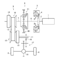
- FIG. 6 is a skeleton diagram for explaining an example of the configuration of the power transmission device.
- the power transmission device shown in FIG. 6 has a power source 1 such as an engine or a motor. Further, a hybrid drive device including an engine and a motor may be used as the power source 1. In the example described below, the engine 1 is used as a power source.
- the torque converter 3 is connected to the output shaft 2 of the engine 1.
- the torque converter 3 is configured in the same manner as conventionally known, and transmits power by a fluid flow and is in a converter region where the rotational speed on the input side is larger than the rotational speed on the output side.
- the torque can be amplified and output.
- the torque converter 3 is provided with a lockup clutch 4 that directly outputs the torque inputted by engaging.
- the forward / reverse switching mechanism 6 is connected to the output shaft 5 of the torque converter 3.
- This forward / reverse switching mechanism 6 is configured in the same manner as conventionally known, and is engaged when the vehicle travels forward to input shaft 5 (output shaft 5 of torque converter 3).
- a clutch C1 that integrally rotates the output shaft 7 and a brake B1 that is engaged when the vehicle travels backward to reverse the rotational direction of the input shaft 5 and the output shaft 7. Note that when the transmission of power between the engine 1 and the drive wheels 8 is interrupted, in other words, when the neutral state is established, both the clutch C1 and the brake B1 are released.
- a belt type continuously variable transmission (hereinafter referred to as CVT) 9 is connected to the output shaft 7 of the forward / reverse switching mechanism 6.
- the CVT 9 shown in FIG. 1 is arranged in parallel with the primary pulley 10 connected to the output shaft 7 of the forward / reverse switching mechanism 6 (hereinafter sometimes referred to as the input shaft 7 of the CVT 9) and the input shaft 7 of the CVT 9.
- the CVT 9 is configured by the rotating shaft 11, the secondary pulley 12 connected to the rotating shaft 11, and the endless belt 13 wound around the pulleys 10 and 12.
- the primary pulley 10 is provided with a slide mechanism 14 that changes the winding radius of the belt 13 by changing the width of the pulley groove.
- a hydraulic actuator that generates a thrust corresponding to the hydraulic pressure an electric actuator that generates a thrust corresponding to the energized power, or the like can be used as the slide mechanism 14.
- the secondary pulley 12 is provided with a torque cam 15 that changes the frictional force between the belt 13 and the pulleys 10 and 12 by generating a thrust according to the input torque. Therefore, the transmission torque capacity of the CVT 9 changes according to the frictional force between the belt 13 and the pulleys 10 and 12.
- An output gear 16 is connected to the output side of the torque cam 15, and torque is transmitted to the drive wheels 8 through the output gear 16, the gear train portion 17 and the differential gear 18.
- the shaft support structure in the CVT 9 prevents the input shaft 7 and the rotating shaft 11 of the CVT 9 from being bent and deformed by the tension of the belt 13 wound around the pulleys 10 and 12 as described above. It is configured as follows.
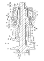
- An example of the configuration is shown in FIG. FIG. 1 shows a torque cam 15 and an output gear 16 arranged concentrically on the same axis as the rotation axis of the secondary pulley 12.
- the upper side of the central axis shows a state in which the groove width of the secondary pulley 12 is wide, that is, a state where the gear ratio is small, and the lower side of the central axis in FIG.
- a state where the width is narrow, that is, a state where the gear ratio is large is shown.
- the left side in FIG. 1 is referred to as an input side
- the right side is referred to as an output side.
- the secondary pulley 12 shown in FIG. 1 can be moved back and forth in the axial direction with respect to the rotating shaft 11 and can rotate integrally with the rotating shaft 11.
- the conical fixed sheave 19 is integrally formed on the input side of the rotating shaft 11. It is comprised by the cone-shaped movable sheave 20 fitted.
- the configuration of the movable sheave 20 will be described in detail.
- the boss portion 22 of the conical portion 21 is connected to the rotary shaft 11 via a connecting mechanism 23 such as a spline or a key so as to be integrally rotatable.
- a torque cam 15 is provided so as to press the movable sheave 20 toward the fixed sheave 19 according to the torque transmitted to the movable sheave 20.
- the secondary pulley 12 shown in FIG. 1 is configured such that torque input from the belt 13 to the fixed sheave 19 is transmitted to the movable sheave 20 via the coupling mechanism 23. Accordingly, all of the torque transmitted from the belt 13 to the fixed sheave 19 and the movable sheave 20 is input to the torque cam 15.
- a bush 24 is provided on the boss portion 22 in order to reduce sliding resistance between the outer peripheral surface of the rotating shaft 11 and the inner peripheral surface of the boss portion 22 in the axial direction.
- the torque cam 15 is formed in a cylindrical shape so as to be fitted to the outer peripheral side of the boss portion 22.
- the torque cam 15 When torque is input from the movable sheave 20, the torque cam 15 not only transmits the input torque to the output side, but also applies a thrust according to the input torque to the movable sheave 20. It is configured. Therefore, a plurality of concave portions 25 are formed at predetermined intervals in the circumferential direction on the outer peripheral surface of the boss portion 22 on the conical portion 21 side, and the side wall surfaces of the concave portions 25 are formed to be inclined. Then, it calls the inclined surface 25a.
- a plurality of convex portions 26 are formed at predetermined intervals in the circumferential direction at the input side end portion of the torque cam 15 so as to transmit torque in contact with the inclined surface 25a.
- the side wall surface of the convex portion 26 is formed to be inclined at the same angle as the inclined surface 25a of the concave portion 25, and will be referred to as an inclined surface 26a in the following description. Even when the movable sheave 21 is moved to the most input side in order to set the minimum speed ratio, the tip of the convex portion 26 and the bottom portion of the concave portion 25 are not in contact with each other.
- a thrust to be applied to the movable sheave 20 is determined in advance so that the belt 13 and the pulley 12 do not slip when the assumed maximum torque is input to the torque cam 15, and the estimated maximum thrust is assumed.
- the inclination angle is determined from the input torque.
- a thrust bearing 27 is disposed between the output side end of the torque cam 15 and the nut 28.
- the outer diameter of the torque cam 15 on the output side is formed smaller than the outer diameter on the input side.
- An output gear 16 of an external gear corresponding to the output member in the present invention is fitted to the output side of the torque cam 15. Specifically, the outer peripheral surface on the output side of the torque cam 15 thus reduced in diameter and the inner peripheral surface of the output gear 16 are in spline engagement.
- a portion where the torque cam 15 and the output gear 16 are engaged is referred to as a spline engaging portion 29.
- the CVT 9 shown in FIG. 6 is a dry belt-type continuously variable transmission in which no lubricating oil is interposed between the belt 13 and the pulley surface. Therefore, the input side on which the secondary pulley 12 in FIG. 1 is disposed is maintained in a dry state, and the lubricating oil supplied to the output gear 16 and the like is prevented from flowing into the secondary pulley 12 side.
- a seal member 30 such as an O-ring is provided between the inner peripheral surface of the central portion of the torque cam 15 and the outer peripheral surface of the rotary shaft 11 in the axial direction.
- a seal member 32 such as an O-ring is provided between the outer peripheral surface of the torque cam 15 and the case 31.
- the seal member 32 is provided at a location where the outer diameter is smaller than the location where the output gear 16 is connected to the torque cam 15 on the input side. Therefore, the lubricating oil can be supplied to the space on the output side from the seal members 30 and 32 in FIG. 1 where the members that require lubrication such as the output gear 16 are provided, and the secondary pulley 12 is provided. Inflow of lubricating oil to the input side is prevented by the seal members 30 and 32.
- the movable sheave 20 moves relative to the torque cam 15 or the rotary shaft 11 in the axial direction as the speed ratio is changed. Therefore, in order to reduce the friction loss between the inclined surface 25a and the inclined surface 26a, a carbon material chip is attached to the side wall surface of the convex portion 26a of the torque cam 15.
- the spline 23 connecting the movable sheave 20 and the rotary shaft 11 and the bush 24 provided in the gap are covered with a resin material.
- the input side end portion of the rotary shaft 11 shown in FIG. 1 is rotatably supported by a first ball bearing 33 fixed to the case 31.
- the first ball bearing 33 is disposed so that the side surface of the inner race 33 a to which the input side end of the rotating shaft 11 is fitted and the side surface on the inner peripheral side of the fixed sheave 19 are in contact with each other.
- the torque cam 15 is rotatably fitted to the second ball bearing 34 at the center thereof.
- the outer race 34 b of the second ball bearing 34 is fixed to the case 31, and the inner race 34 a is integrated with the torque cam 15 by the step portion between the large diameter portion and the small diameter portion of the torque cam 15 and the nut 35. It is pinched so as to rotate.
- the second ball bearing 34 is provided on the input side with respect to the seal member 32. That is, each of the ball bearings 33 and 34 is provided in a dry space where no lubricating oil is supplied. Therefore, a lubricant is sealed between the inner race 33a and the outer race 33b of the bearing 33, and similarly, a lubricant is sealed between the inner race 34a and the outer race 34b of the radial bearing 34. .
- the inclined surface 25a of the concave portion 25 of the movable sheave 20 and the inclined surface 26a of the convex portion 26 of the torque cam 15 are brought into contact with each other to slide with each other. And relative rotation.
- the movable sheave 20 and the rotary shaft 11 are fitted by the spline 23 so as to be integrally rotatable. Therefore, the first cam in the present invention is provided between the inner peripheral surface of the torque cam 15 and the outer peripheral surface of the rotary shaft 11 so as to enable relative rotation between the torque cam 15 and the rotary shaft 11 when changing the gear ratio.
- Two roller bearings 36 and 37 corresponding to the bearing, the third bearing, and the fourth bearing are provided.
- each of the first roller bearing 36 and the second roller bearing 37 includes a plurality of rollers 38 (39) disposed at predetermined intervals in the circumferential direction on the outer peripheral surface of the rotary shaft 11, in the torque cam 15.
- the first rotor bearing 36 and the second roller bearing 37 are arranged on the output side of the seal member 30 in the axial direction of the rotary shaft 11. They are arranged at a predetermined interval.
- the first roller bearing 36 is disposed at a position overlapping the second ball bearing 34 and the nut 35 in the axial direction
- the second roller bearing 37 is formed by the spline engaging portion 29 or the external teeth of the output gear 16. It is arrange
- the first roller bearing 36, the seal member 32, and a third ball bearing 42 described later are arranged so as to partially overlap each other in the axial direction.
- two roller bearings 36 and 37 are interposed between the torque cam 15 and the rotating shaft 11 so as to allow relative rotation between the torque cam 15 and the rotating shaft 11. 37 is subjected to a radial load from the torque cam 15 and a radial load from the rotary shaft 11.
- the number of these roller bearings can be changed arbitrarily. For example, by using a bearing having a length from the first roller bearing 36 to the second roller bearing 37 shown in FIG. 1, the number of roller bearings can be reduced to one. Or you may arrange
- the output gear 16 is connected to the torque cam 15 via the spline engaging portion 29, and both the input side and the output side are rotated by the third ball bearing 42 and the fourth ball bearing 43 in the axial direction. Supported as possible. Specifically, a cylindrical portion 16a protruding to the input side is formed on the outer peripheral side in the radial direction of the output gear 16. The inner race 42 a of the third ball bearing 42 is fixed to the outer peripheral surface of the cylindrical portion 16 a, and the outer race 42 b of the third ball bearing 42 is fixed to the case 31. On the other hand, on the inner peripheral side of the output gear 16, a cylindrical portion 16b protruding to the output side is formed.
- the inner race 43 a of the fourth ball bearing 43 is fixed to the outer peripheral surface of the cylindrical portion 16 b, and the outer race 43 b of the fourth ball bearing 43 is fixed to the case 31.
- the sealing member 32 described above is connected to the inner peripheral surface of the cylindrical portion 16a and the outer peripheral surface of the torque cam 15. Can be accommodated in a space formed between the two.
- the first roller bearing 36 is also disposed so as to overlap the inner peripheral side of the third ball bearing 42 in the axial direction.
- the third ball bearing 42 corresponds to the second bearing in the present invention.
- the movable sheave 20 is fitted to the rotary shaft 11 via the bush 24, and the torque cam 15 is fitted to the rotary shaft 11 via the roller bearings 36 and 37. ing. Therefore, the rotating shaft 11, the movable sheave 20, and the torque cam 15 constitute one rotating shaft. Therefore, in the example shown in FIG. 1, the first ball bearing 33 and the second ball bearing 34 are configured to support the rotating shaft constituted by the rotating shaft 11, the movable sheave 20, and the torque cam 15. ing.
- the rotation shaft constituted by the rotation shaft 11, the movable sheave 20, and the torque cam 15 may be referred to as “shaft assembly S”.
- the portion of the shaft assembly S on the output side is displaced downward from the second ball bearing 34. Therefore, if the distance between the second ball bearing 34 and the output gear 16 is long, the output gear 16 will be greatly displaced. As a result, the meshing of the output gear 16 is deteriorated and noise, vibration, power loss, etc. are increased. There is a possibility that.
- the cylindrical portion 16a into which the third ball bearing 42 is fitted is formed so as to protrude toward the input side, and the seal member 32 is disposed on the inner peripheral side of the cylindrical portion 16a.
- the output gear 16 can be arranged on the input side.
- the shaft length of the shaft assembly S itself can be shortened.
- the CVT 9 can be reduced in size in the width direction.
- the spline engaging portion 29 and the second roller bearing 37 are arranged so as to overlap in the axial direction, the shaft length of the shaft assembly S can be further shortened, and as a result, the CVT 9 can be further downsized. can do.
- the seal member 32 is disposed between the rotating torque cam 15 and the fixed case 31, either the inner peripheral surface or the outer peripheral surface of the seal member 32 is relative to the torque cam 15 or the case 31. Rotate. Therefore, by disposing the seal member 32 at a position close to the center side, the relative peripheral speed can be reduced, so that a decrease in durability of the seal member 32 can be suppressed.
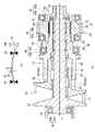
- FIG. 2A is a diagram for explaining a state in which the shaft assembly S is bent and deformed by the load transmitted from the belt 13.
- the shaft assembly S is rotatably supported by the first ball bearing 33 and the second ball bearing 34. Therefore, when a load directed upward in FIG. 2 acts on the shaft assembly S from the belt 13, the shaft assembly S bends as indicated by a broken line in FIG. Therefore, in the example shown in FIG. 2, the amount of deflection of the shaft assembly S between the first ball bearing 33 and the second ball bearing 34 is reduced by limiting the amount of displacement on the output side of the second ball bearing 34. Is configured to do.
- FIG. 2A is a diagram illustrating an example of the bending deformation of the shaft assembly S when the amount of displacement on the output side of the second ball bearing 34 is restricted by the A portion.
- the amount of displacement on the output side of the second ball bearing 34 can be limited, for example, by closing the gap of the spline engaging portion 29 in FIG.
- the gap between the spline engaging portions 29, more specifically, the gap between the outer peripheral surface of the torque cam 15 and the inner peripheral surface of the output gear 16 is formed to be smaller than the calculated displacement amount. Therefore, even when a load is applied from the belt 13 to the shaft assembly S, the amount of displacement of the spline engaging portion 29 is suppressed in this way, so that the space between the first ball bearing 33 and the second ball bearing 34 is reduced. Can be suppressed.
- the amount of displacement of the output side portion of the second ball bearing 34 reduces the gap between the inner peripheral surface of the cylindrical portion 16a and the outer peripheral surface of the torque cam 15 in the output gear 16, as shown in FIG. Or by contacting.
- the spline engaging portion 29 corresponds to the fitting portion in the present invention. Further, in FIG. 2B, the seal member 32 is not provided, and a bearing that supports the output gear 16 is indicated as a fifth ball bearing 46.
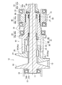
- FIG. 3 Another example of the shaft support structure in the CVT 9 according to the present invention is shown in FIG.
- the same referential mark is attached
- the input-side third roller bearing 47 disposed between the rotating shaft 11 and the torque cam 15 is disposed on the input side with respect to the second ball bearing 34 in the axial direction.
- Other configurations can be the same as the example shown in FIG. 1, but in the example shown in FIG. 3, the output side roller bearing disposed between the rotating shaft 11 and the torque cam 15 is the fourth. This is referred to as a roller bearing 48.
- the first ball bearing 33 corresponds to the sixth bearing in the present invention
- the second ball bearing 34 corresponds to the seventh bearing in the present invention
- the third roller bearing 47 corresponds to the eighth bearing in the present invention
- the fourth roller bearing 48 corresponds to the ninth bearing in the present invention.
- a portion of a portion where the torque cam 15 is fitted to the rotary shaft 11 via a roller bearing is disposed between the ball bearings 33 and 34 that support the shaft assembly S.
- the shaft assembly S is configured to improve the rigidity between the ball bearings 33 and 34.
- one third roller bearing 47 is disposed on the input side of the second ball bearing 34. Since the rotary shaft 11 and the torque cam 15 are integrated via the third roller bearing 47 and the fourth roller bearing 48, the cross section of the shaft assembly S between the third roller bearing 47 and the fourth roller bearing 48. The second moment increases.
- the portion where the cross-sectional secondary moment is increased is supported by the second ball bearing 34, when the load is applied from the belt 13, the portion where the cross-sectional secondary moment of the shaft assembly S is increased, Since it acts so as to improve the rigidity of the portion of the shaft assembly S that is bent and deformed between the first ball bearing 33 and the second ball bearing 34, the bending between the first ball bearing 33 and the second ball bearing 34. The amount of deformation can be reduced. As a result, the displacement amount of the shaft assembly S can be reduced.
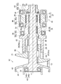
- FIG. 4 is a diagram for explaining the structure.
- the configuration other than the configuration of the fixed sheave 19 can be the same as the configuration of FIGS. 1 to 3.
- the back surface of the fixed sheave 19 is also formed in a conical shape like the pulley surface. That is, the fixed sheave 19 is formed so that the conical portion has a uniform plate thickness. In other words, the inner peripheral portion of the back surface of the fixed sheave 19 is recessed.
- a cylindrical portion 44 that protrudes toward the back side, that is, opens to the back side is formed on the outer peripheral side of the fixed sheave 19.
- An annular protrusion 45 that protrudes toward the inner periphery is formed at the opening end of the cylindrical portion 44.
- a bearing 49 that supports the rotating shaft 11 is disposed inside the cylindrical portion 44.
- the distance between the position where the load acts on the shaft assembly S from the belt 13 and the sixth ball bearing 49 is shortened by forming the back side of the fixed sheave conically along the pulley surface. Can do.
- the sixth ball bearing 49 can be disposed at a position close to the second ball bearing 34.
- the cylindrical portion 44 is disposed on the outer peripheral side of the sixth ball bearing 49, even when the lubricating oil sealed in the sixth ball bearing 49 leaks from the sixth ball bearing 49, the lubricating oil Can be prevented from scattering to the outer peripheral side due to centrifugal force. More specifically, when increasing the gear ratio, the pulley groove of the primary pulley 10 becomes large as shown in FIG. 1, and therefore, although not particularly illustrated, the primary pulley is arranged on the outer peripheral side of the sixth ball bearing 49. Ten pulley surfaces may be located. Therefore, the configuration shown in FIG.
- the cylindrical portion 44 and the protruding portion 45 may be formed integrally with the fixed sheave 19, and the cylindrical portion 44 and the protruding portion 45 are formed by other members as shown in FIG. It may be integrated with.
- the cylindrical portion 44 formed integrally with the fixed sheave 19 as described above and the cylindrical portion 44 formed by other members as shown in FIG. 5 correspond to the first cylindrical portion and the second cylindrical portion in the present invention.
- the sixth ball bearing 49 provided on the inner peripheral side of the cylindrical portion 44 corresponds to the fifth bearing and the sixth bearing in the present invention.
- the movable sheave 20 is described as being connected to the rotating shaft 11 by the connecting mechanism 23 such as a spline.
- the movable sheave 20 is slid in the axial direction of the rotating shaft 11. Therefore, the structure of the coupling mechanism 23 is not particularly limited.
- the shaft to be supported is not limited to the rotating shaft 11 connected to the secondary pulley 12 but may be a shaft connected to the primary pulley 10.
Landscapes
- Engineering & Computer Science (AREA)
- General Engineering & Computer Science (AREA)
- Mechanical Engineering (AREA)
- Transmissions By Endless Flexible Members (AREA)
- General Details Of Gearings (AREA)
Abstract
Description
Claims (7)
- 回転軸に一体化されている固定シーブおよび前記回転軸の外周側に軸線方向に前後動できるように嵌合された可動シーブにより構成されたプーリと、前記プーリに巻き掛けられたベルトと、伝達されるトルクに応じて軸線方向の推力を発生させるために、前記可動シーブの背面側に該可動シーブと同一軸線上に、前記回転軸に回転可能に嵌合させられたトルクカムと、前記トルクカムと一体に回転するように前記トルクカムの外周側に嵌合させられた出力部材とを備えたベルト式無段変速機の軸支持構造において、
前記回転軸の外周面と前記トルクカムの内周面との間にこれら回転軸とトルクカムとを相対回転可能に支持する単一もしくは複数の第1軸受が設けられ、
一つの前記第1軸受の半径方向で外周側に、前記出力部材の軸線方向での一方の端部をケースに対して回転可能に支持する第2軸受が設けられ、
前記トルクカムの外周面と前記第2軸受の間に形成されるスペースに前記トルクカムの外周面に嵌合させられたシール部材が配置されている
ことを特徴とするベルト式無段変速機の軸支持構造。 - 前記第1軸受は、軸線方向に並んで配置された第3軸受と第4軸受とを少なくとも含み、
前記第3軸受と前記第4軸受とのいずれか一方の軸受が、軸線方向において前記出力部材と重なって配置されている
ことを特徴とする請求項1に記載のベルト式無段変速機の軸支持構造。 - 前記固定シーブは、前記ベルトと接触するプーリ面とは反対側の背面における内周部分が、外周部分よりも軸線方向において前記ベルトが巻き掛けられている方向に窪んだ凹部と、前記背面から軸線方向に突出した第1円筒部とを有し、
前記第1円筒部の内周側に、前記回転軸を前記ケースに対して回転可能に支持する第5軸受を備えている
ことを特徴とする請求項1または2に記載のベルト式無段変速機の軸支持構造。 - 回転軸に一体化されている固定シーブおよび前記回転軸の外周側に軸線方向に前後動できるように嵌合された可動シーブにより構成されたプーリと、前記プーリに巻き掛けられたベルトと、伝達されるトルクに応じて軸線方向の推力を発生させるために、前記可動シーブの背面側に該可動シーブと同一軸線上に、前記回転軸に回転可能に嵌合させられたトルクカムと、前記トルクカムと一体に回転するように前記トルクカムの外周側に嵌合させられた出力部材とを備えたベルト式無段変速機の軸支持構造において、
前記回転軸における前記固定シーブ側の端部が第6軸受によってケースに対して回転可能に支持され、
前記トルクカムが該トルクカムの外周面に嵌合させられた第7軸受によって前記ケースに対して回転可能に支持され、
前記トルクカムの内周面と前記回転軸の外周面との間にこれらトルクカムと回転軸とを相対回転可能に支持しかつ軸線方向に並んで配置された第8軸受と第9軸受とを少なくとも備え、
前記第8軸受が、軸線方向において前記第6軸受と前記第7軸受との間に配置されるとともに、前記第9軸受が、軸線方向において前記第7軸受を挟んで前記第8軸受とは反対側に配置されている
ことを特徴とするベルト式無段変速機の軸支持構造。 - 前記第8軸受は、軸線方向において前記出力部材と重なって配置されている
ことを特徴とする請求項4に記載のベルト式無段変速機の軸支持構造。 - 前記固定シーブは、前記ベルトと接触するプーリ面とは反対側の背面における内周部分が、外周部分よりも軸線方向において前記ベルトが巻き掛けられている方向に窪んだ凹部と、前記背面から軸線方向に突出した第2円筒部とを有し、
前記第2円筒部の内周側に、前記第6軸受が配置されている
ことを特徴とする請求項4または5に記載のベルト式無段変速機の軸支持構造。 - 前記出力部材は、前記トルクカムが半径方向に変位する量を規制する嵌合部を更に備えていることを特徴とする請求項1ないし6のいずれかに記載のベルト式無段変速機の軸支持構造。
Priority Applications (4)
| Application Number | Priority Date | Filing Date | Title |
|---|---|---|---|
| JP2015507953A JPWO2014155835A1 (ja) | 2013-03-27 | 2013-12-04 | ベルト式無段変速機における軸支持構造 |
| CN201380075095.7A CN105051423A (zh) | 2013-03-27 | 2013-12-04 | 带式无级变速器中的轴支承构造 |
| US14/779,250 US20160047457A1 (en) | 2013-03-27 | 2013-12-04 | Shaft supporting structure of belt-driven continuously variable transmission |
| DE112013006879.6T DE112013006879T5 (de) | 2013-03-27 | 2013-12-04 | Wellenlagerstruktur eines riemengetriebenen kontinuierlich variablen Getriebes |
Applications Claiming Priority (2)
| Application Number | Priority Date | Filing Date | Title |
|---|---|---|---|
| JP2013065555 | 2013-03-27 | ||
| JP2013-065555 | 2013-03-27 |
Publications (1)
| Publication Number | Publication Date |
|---|---|
| WO2014155835A1 true WO2014155835A1 (ja) | 2014-10-02 |
Family
ID=51622870
Family Applications (1)
| Application Number | Title | Priority Date | Filing Date |
|---|---|---|---|
| PCT/JP2013/082542 Ceased WO2014155835A1 (ja) | 2013-03-27 | 2013-12-04 | ベルト式無段変速機における軸支持構造 |
Country Status (5)
| Country | Link |
|---|---|
| US (1) | US20160047457A1 (ja) |
| JP (1) | JPWO2014155835A1 (ja) |
| CN (1) | CN105051423A (ja) |
| DE (1) | DE112013006879T5 (ja) |
| WO (1) | WO2014155835A1 (ja) |
Cited By (1)
| Publication number | Priority date | Publication date | Assignee | Title |
|---|---|---|---|---|
| CN111412266A (zh) * | 2020-03-26 | 2020-07-14 | 东风汽车集团有限公司 | 一种适用于混合动力变速箱电机齿轴的安装结构 |
Families Citing this family (4)
| Publication number | Priority date | Publication date | Assignee | Title |
|---|---|---|---|---|
| US11421771B2 (en) * | 2015-10-30 | 2022-08-23 | Bombardier Recreational Products Inc. | Continuously variable transmission drive pulley |
| CN109154361B (zh) * | 2016-06-07 | 2021-06-04 | 爱信艾达株式会社 | 变速装置 |
| DE102018203073A1 (de) * | 2018-03-01 | 2019-09-05 | Zf Friedrichshafen Ag | Antriebsanordnung für ein Schienenfahrzeug |
| NL1043519B1 (en) * | 2019-12-23 | 2021-09-02 | Bosch Gmbh Robert | A transverse segment for a drive belt, a drive belt including such transverse segment and a continuously variable transmission with the drive belt including such transverse segment |
Citations (5)
| Publication number | Priority date | Publication date | Assignee | Title |
|---|---|---|---|---|
| JPS6179061A (ja) * | 1984-09-25 | 1986-04-22 | Aisin Warner Ltd | Vベルト式無段変速機 |
| JPH05118396A (ja) * | 1991-10-24 | 1993-05-14 | Bando Chem Ind Ltd | ベルト式変速装置 |
| JP2005337459A (ja) * | 2004-05-28 | 2005-12-08 | Toyota Motor Corp | ベルト式無段変速機 |
| JP2008064125A (ja) * | 2006-09-04 | 2008-03-21 | Toyota Motor Corp | ベルト式無段変速機 |
| JP2010106957A (ja) * | 2008-10-30 | 2010-05-13 | Ntn Corp | ベルト式無段変速機 |
Family Cites Families (5)
| Publication number | Priority date | Publication date | Assignee | Title |
|---|---|---|---|---|
| JP3691717B2 (ja) * | 2000-03-22 | 2005-09-07 | ジヤトコ株式会社 | ハイブリッド車両の変速機ユニット |
| DE10353130A1 (de) * | 2003-11-14 | 2005-06-09 | Daimlerchrysler Ag | Lagerung und stufenloses Getriebe mit einer Lagerung |
| ATE406535T1 (de) * | 2004-10-23 | 2008-09-15 | Luk Lamellen & Kupplungsbau | Kegelscheibenumschlingungsgetriebe, sowie fahrzeug mit einem derartigem getriebe |
| JP5692358B2 (ja) * | 2011-03-23 | 2015-04-01 | トヨタ自動車株式会社 | ベルト式無段変速機 |
| JP2016056839A (ja) * | 2014-09-08 | 2016-04-21 | トヨタ自動車株式会社 | ベルト式無段変速機の軸支持構造 |
-
2013
- 2013-12-04 US US14/779,250 patent/US20160047457A1/en not_active Abandoned
- 2013-12-04 DE DE112013006879.6T patent/DE112013006879T5/de not_active Withdrawn
- 2013-12-04 CN CN201380075095.7A patent/CN105051423A/zh active Pending
- 2013-12-04 WO PCT/JP2013/082542 patent/WO2014155835A1/ja not_active Ceased
- 2013-12-04 JP JP2015507953A patent/JPWO2014155835A1/ja active Pending
Patent Citations (5)
| Publication number | Priority date | Publication date | Assignee | Title |
|---|---|---|---|---|
| JPS6179061A (ja) * | 1984-09-25 | 1986-04-22 | Aisin Warner Ltd | Vベルト式無段変速機 |
| JPH05118396A (ja) * | 1991-10-24 | 1993-05-14 | Bando Chem Ind Ltd | ベルト式変速装置 |
| JP2005337459A (ja) * | 2004-05-28 | 2005-12-08 | Toyota Motor Corp | ベルト式無段変速機 |
| JP2008064125A (ja) * | 2006-09-04 | 2008-03-21 | Toyota Motor Corp | ベルト式無段変速機 |
| JP2010106957A (ja) * | 2008-10-30 | 2010-05-13 | Ntn Corp | ベルト式無段変速機 |
Cited By (1)
| Publication number | Priority date | Publication date | Assignee | Title |
|---|---|---|---|---|
| CN111412266A (zh) * | 2020-03-26 | 2020-07-14 | 东风汽车集团有限公司 | 一种适用于混合动力变速箱电机齿轴的安装结构 |
Also Published As
| Publication number | Publication date |
|---|---|
| CN105051423A (zh) | 2015-11-11 |
| DE112013006879T5 (de) | 2015-12-10 |
| JPWO2014155835A1 (ja) | 2017-02-16 |
| US20160047457A1 (en) | 2016-02-18 |
Similar Documents
| Publication | Publication Date | Title |
|---|---|---|
| US20150000999A1 (en) | Torsional vibration damping device | |
| CN103459890B (zh) | 带式无级变速器 | |
| WO2014155835A1 (ja) | ベルト式無段変速機における軸支持構造 | |
| US11408487B2 (en) | Forward/reverse switching mechanism | |
| JPWO2020084936A1 (ja) | 無段変速機 | |
| WO2011108316A1 (ja) | スプロケット支持構造 | |
| JP2006010080A (ja) | 発進クラッチ及びトルク検出装置を有する固定ディスクアセンブリ | |
| JP2001330089A (ja) | 巻き掛け伝動装置およびベルト式無段変速機 | |
| JPWO2014115384A1 (ja) | ベルト式無段変速機 | |
| JP2012097867A (ja) | 回転軸のシール構造 | |
| JP6990323B2 (ja) | 無段変速機 | |
| JP4978557B2 (ja) | 摩擦車式の無段変速装置 | |
| US6960151B2 (en) | Toroidal continuously variable transmission | |
| JP4894552B2 (ja) | 車両用ベルト式無段変速機 | |
| JPH03149441A (ja) | ベルト式無段変速装置 | |
| JP6129675B2 (ja) | 動力伝達機構 | |
| JP2015215065A (ja) | 車両用無段変速機 | |
| JP5418152B2 (ja) | 摩擦車式の無段変速装置 | |
| JP6517688B2 (ja) | 動力伝達装置 | |
| JP5968287B2 (ja) | 無終端巻き掛け伝動機の軸受け構造 | |
| JP6493346B2 (ja) | 車両用無段変速機 | |
| JP4710726B2 (ja) | トロイダル型無段変速機 | |
| JP2015113934A (ja) | トルクカム装置 | |
| JP2009002489A (ja) | トロイダル型無段変速機 | |
| JP5969431B2 (ja) | 無段変速機 |
Legal Events
| Date | Code | Title | Description |
|---|---|---|---|
| WWE | Wipo information: entry into national phase |
Ref document number: 201380075095.7 Country of ref document: CN |
|
| 121 | Ep: the epo has been informed by wipo that ep was designated in this application |
Ref document number: 13880106 Country of ref document: EP Kind code of ref document: A1 |
|
| ENP | Entry into the national phase |
Ref document number: 2015507953 Country of ref document: JP Kind code of ref document: A |
|
| WWE | Wipo information: entry into national phase |
Ref document number: 14779250 Country of ref document: US |
|
| WWE | Wipo information: entry into national phase |
Ref document number: 1120130068796 Country of ref document: DE Ref document number: 112013006879 Country of ref document: DE |
|
| 122 | Ep: pct application non-entry in european phase |
Ref document number: 13880106 Country of ref document: EP Kind code of ref document: A1 |