WO2014148602A1 - モータ装置 - Google Patents
モータ装置 Download PDFInfo
- Publication number
- WO2014148602A1 WO2014148602A1 PCT/JP2014/057746 JP2014057746W WO2014148602A1 WO 2014148602 A1 WO2014148602 A1 WO 2014148602A1 JP 2014057746 W JP2014057746 W JP 2014057746W WO 2014148602 A1 WO2014148602 A1 WO 2014148602A1
- Authority
- WO
- WIPO (PCT)
- Prior art keywords
- connector
- shaft
- plate
- motor
- worm wheel
- Prior art date
Links
Images


Classifications
-
- H—ELECTRICITY
- H02—GENERATION; CONVERSION OR DISTRIBUTION OF ELECTRIC POWER
- H02K—DYNAMO-ELECTRIC MACHINES
- H02K11/00—Structural association of dynamo-electric machines with electric components or with devices for shielding, monitoring or protection
- H02K11/0094—Structural association with other electrical or electronic devices
-
- H—ELECTRICITY
- H02—GENERATION; CONVERSION OR DISTRIBUTION OF ELECTRIC POWER
- H02K—DYNAMO-ELECTRIC MACHINES
- H02K23/00—DC commutator motors or generators having mechanical commutator; Universal AC/DC commutator motors
- H02K23/02—DC commutator motors or generators having mechanical commutator; Universal AC/DC commutator motors characterised by arrangement for exciting
- H02K23/04—DC commutator motors or generators having mechanical commutator; Universal AC/DC commutator motors characterised by arrangement for exciting having permanent magnet excitation
-
- B—PERFORMING OPERATIONS; TRANSPORTING
- B60—VEHICLES IN GENERAL
- B60S—SERVICING, CLEANING, REPAIRING, SUPPORTING, LIFTING, OR MANOEUVRING OF VEHICLES, NOT OTHERWISE PROVIDED FOR
- B60S1/00—Cleaning of vehicles
- B60S1/02—Cleaning windscreens, windows or optical devices
- B60S1/04—Wipers or the like, e.g. scrapers
- B60S1/06—Wipers or the like, e.g. scrapers characterised by the drive
- B60S1/08—Wipers or the like, e.g. scrapers characterised by the drive electrically driven
-
- H—ELECTRICITY
- H01—ELECTRIC ELEMENTS
- H01R—ELECTRICALLY-CONDUCTIVE CONNECTIONS; STRUCTURAL ASSOCIATIONS OF A PLURALITY OF MUTUALLY-INSULATED ELECTRICAL CONNECTING ELEMENTS; COUPLING DEVICES; CURRENT COLLECTORS
- H01R13/00—Details of coupling devices of the kinds covered by groups H01R12/70 or H01R24/00 - H01R33/00
- H01R13/02—Contact members
- H01R13/10—Sockets for co-operation with pins or blades
- H01R13/11—Resilient sockets
-
- H—ELECTRICITY
- H01—ELECTRIC ELEMENTS
- H01R—ELECTRICALLY-CONDUCTIVE CONNECTIONS; STRUCTURAL ASSOCIATIONS OF A PLURALITY OF MUTUALLY-INSULATED ELECTRICAL CONNECTING ELEMENTS; COUPLING DEVICES; CURRENT COLLECTORS
- H01R39/00—Rotary current collectors, distributors or interrupters
- H01R39/02—Details for dynamo electric machines
- H01R39/38—Brush holders
- H01R39/383—Brush holders characterised by the electrical connection to the brush holder
-
- H—ELECTRICITY
- H02—GENERATION; CONVERSION OR DISTRIBUTION OF ELECTRIC POWER
- H02K—DYNAMO-ELECTRIC MACHINES
- H02K1/00—Details of the magnetic circuit
- H02K1/06—Details of the magnetic circuit characterised by the shape, form or construction
- H02K1/12—Stationary parts of the magnetic circuit
- H02K1/17—Stator cores with permanent magnets
-
- H—ELECTRICITY
- H02—GENERATION; CONVERSION OR DISTRIBUTION OF ELECTRIC POWER
- H02K—DYNAMO-ELECTRIC MACHINES
- H02K11/00—Structural association of dynamo-electric machines with electric components or with devices for shielding, monitoring or protection
- H02K11/20—Structural association of dynamo-electric machines with electric components or with devices for shielding, monitoring or protection for measuring, monitoring, testing, protecting or switching
- H02K11/21—Devices for sensing speed or position, or actuated thereby
-
- H—ELECTRICITY
- H02—GENERATION; CONVERSION OR DISTRIBUTION OF ELECTRIC POWER
- H02K—DYNAMO-ELECTRIC MACHINES
- H02K11/00—Structural association of dynamo-electric machines with electric components or with devices for shielding, monitoring or protection
- H02K11/30—Structural association with control circuits or drive circuits
- H02K11/38—Control circuits or drive circuits associated with geared commutator motors of the worm-and-wheel type
-
- H—ELECTRICITY
- H02—GENERATION; CONVERSION OR DISTRIBUTION OF ELECTRIC POWER
- H02K—DYNAMO-ELECTRIC MACHINES
- H02K5/00—Casings; Enclosures; Supports
- H02K5/04—Casings or enclosures characterised by the shape, form or construction thereof
- H02K5/08—Insulating casings
-
- H—ELECTRICITY
- H02—GENERATION; CONVERSION OR DISTRIBUTION OF ELECTRIC POWER
- H02K—DYNAMO-ELECTRIC MACHINES
- H02K5/00—Casings; Enclosures; Supports
- H02K5/04—Casings or enclosures characterised by the shape, form or construction thereof
- H02K5/22—Auxiliary parts of casings not covered by groups H02K5/06-H02K5/20, e.g. shaped to form connection boxes or terminal boxes
- H02K5/225—Terminal boxes or connection arrangements
-
- H—ELECTRICITY
- H02—GENERATION; CONVERSION OR DISTRIBUTION OF ELECTRIC POWER
- H02K—DYNAMO-ELECTRIC MACHINES
- H02K7/00—Arrangements for handling mechanical energy structurally associated with dynamo-electric machines, e.g. structural association with mechanical driving motors or auxiliary dynamo-electric machines
- H02K7/10—Structural association with clutches, brakes, gears, pulleys or mechanical starters
- H02K7/116—Structural association with clutches, brakes, gears, pulleys or mechanical starters with gears
- H02K7/1163—Structural association with clutches, brakes, gears, pulleys or mechanical starters with gears where at least two gears have non-parallel axes without having orbital motion
- H02K7/1166—Structural association with clutches, brakes, gears, pulleys or mechanical starters with gears where at least two gears have non-parallel axes without having orbital motion comprising worm and worm-wheel
-
- H—ELECTRICITY
- H02—GENERATION; CONVERSION OR DISTRIBUTION OF ELECTRIC POWER
- H02K—DYNAMO-ELECTRIC MACHINES
- H02K5/00—Casings; Enclosures; Supports
- H02K5/04—Casings or enclosures characterised by the shape, form or construction thereof
- H02K5/14—Means for supporting or protecting brushes or brush holders
- H02K5/143—Means for supporting or protecting brushes or brush holders for cooperation with commutators
- H02K5/148—Slidably supported brushes
Definitions
- the present invention relates to a motor unit including a connector unit to which an external connector is connected and a motor unit to which a drive current is supplied via the connector unit.
- a wiper motor that drives a wiper device mounted on a vehicle such as an automobile.
- the wiper motor is mounted on a motor unit having an armature shaft that rotates when a drive current is supplied, a deceleration mechanism unit that decelerates the rotation of the armature shaft and increases torque, and a motor unit or a deceleration mechanism unit.
- the connector unit is connected, and a drive current is supplied from the external connector to the motor unit via the connector unit.
- a wiper motor described in Patent Document 1 includes a motor subassembly (motor unit) including an armature shaft (armature shaft), a reduction unit subassembly (deceleration mechanism unit) including a reduction mechanism including a worm and a worm wheel, and a motor.
- a brush holder unit (connector unit) including a connector box that is disposed between the sub-assembly and the speed reduction unit sub-assembly and to which an external connector is connected.
- the brush holder that constitutes the brush holder unit is made of an insulating resin material, and is molded into a predetermined shape by injection molding.
- a plurality of internal wirings are embedded in the brush holder by insert molding.
- Each internal wiring that is an insert material is a strip-shaped conductive member that is bent in the X-axis direction, the Y-axis direction, and the Z-axis direction. That is, each internal wiring has a labyrinth shape.
- Each internal wiring is embedded in the brush holder at an interval so as not to interfere with each other. One end side of each internal wiring is drawn into the motor unit and the speed reduction mechanism unit, and the other end side is drawn into the connector box and collected.
- An object of the present invention is to simplify the manufacturing process of a motor device including a wiper motor as much as possible.
- the motor device of the present invention is a motor device including a connector unit to which an external connector for supplying a drive current to the motor unit is connected, and the connector unit has an opening through which an armature shaft extending from the motor unit is inserted.
- each of the conductive members has a connector side connection portion that faces the connector connection portion from a first direction opposite to the insertion direction of the external connector into the insertion hole, and is connected to the external connector, and And a base side connection portion connected to a terminal or wiring provided in the base portion.
- the connector side connecting portions of the respective conductive members are respectively inserted into a plurality of insertion holes provided at different positions in a second direction intersecting the first direction, and the bases of the respective conductive members The side connection parts are arranged at the same position in the second direction.
- a holder member is provided to hold the conductive member between the connector connecting portion and the connector connecting portion facing the connector connecting portion.
- an insulating protrusion interposed between the adjacent conductive members is formed on the inner surface of the holder member facing the connector connecting portion.
- the connector unit is provided with at least a first mounting portion on which the first conductive member is mounted and a second mounting portion on which the second conductive member is mounted.
- the first mounting portion includes a first support surface on which the lower surface of the first conductive member is placed, a first positioning surface that rises from the first support surface and is abutted against a side surface of the first conductive member, Have The second mounting portion extends in parallel with the first support surface from the first positioning surface, and a second support surface on which a lower surface of the second conductive member is placed, and the second support surface And a second positioning surface against which the side surface of the second conductive member is abutted.
- each of the conductive members is an intermediate portion that connects the connector-side connection portion and the base-side connection portion, and includes a flat portion that is parallel to the base-side connection portion.
- the flat portions of the respective conductive members are arranged at different positions in the second direction.
- FIG. 4 is a view taken in the direction of arrow B in FIG. 3. It is a perspective view which shows the positional relationship of an electrical component. It is a perspective view which shows the mounting state of a conductive plate. It is another perspective view which shows the mounting state of a conductive plate. It is a disassembled perspective view which shows the mounting state of a conductive plate and a holder member. It is sectional drawing which shows the mounting state of a conductive plate. It is a perspective view of a holder member.
- FIG. 6 is a plan view of a wiper motor according to Embodiment 2.
- FIG. It is a fragmentary sectional view which follows the AA line of FIG. It is the figure which looked at the connector unit and the worm wheel from the back side of FIG. It is the perspective view which looked at the connector unit from the deceleration mechanism part side.
- FIG. 10 is a plan view showing a speed reduction mechanism portion of a wiper motor according to Embodiment 3.
- FIG. 10 is a plan view of a wiper motor according to Embodiment 4.
- FIG. 21 is a partial sectional view taken along line AA in FIG. 20. It is the perspective view which looked at the worm wheel simple substance from the front side. It is the perspective view which looked at the worm wheel simple substance from the back side. It is the elements on larger scale explaining the positional relationship of a connection part, a gear part side recessed part, and a wheel shaft fixing hole side recessed part.
- FIG. 10 is a plan view showing a speed reduction mechanism portion of a wiper motor according to a fifth embodiment.
- FIG. 10 is a plan view of an electric motor device 301 according to a sixth embodiment. It is a figure which shows the sleeve. It is a perspective view of resin bushing 340. It is a figure which shows the rotation stopping mechanism of resin bush 340. It is a figure which shows the shaft contact part 325.
- FIG. 10 is a plan view showing a speed reduction mechanism portion of a wiper motor according to a fifth embodiment.
- FIG. 10 is a plan view of an electric motor device 401 according to a seventh embodiment. It is sectional drawing of the transmission mechanism 450. FIG. It is a figure which shows the connection plate 457 and the 2nd sector gear 458. FIG. It is a top view which shows the modification (transmission mechanism 4150) of a transmission mechanism. 7 is a cross-sectional view of a transmission mechanism 4150.
- FIG. It is a figure which shows the hollow part 456g of the power transmission member 456.
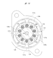
- a wiper motor 10 shown in FIG. 1 is a motor device used as a drive source of a rear wiper device mounted on a rear hatch or the like of a vehicle, and includes a motor unit 20 and a speed reduction mechanism unit 30.
- the motor unit 20 is a four-pole motor with a brush, and includes a yoke 21 as a casing formed of a magnetic steel plate.
- the yoke 21 is formed into a bottomed cylindrical shape by pressing, and a total of four magnets 22 are fixed to the inner peripheral surface. However, only two magnets 22 are shown in FIG. Inside the magnets 22, an armature 23 is rotatably accommodated through a predetermined gap (air gap).
- the armature 23 includes an armature shaft 24 that is rotatably supported by the yoke 21, and a commutator 25 and an armature core 26 are fixed to the armature shaft 24.
- the commutator 25 includes a plurality of segments, and a plurality of armature coils are wound around the armature core 26. Furthermore, the coil end of each armature coil is electrically connected to each segment of the commutator 25.
- a power supply unit 27 having a plurality of brushes that are in sliding contact with the commutator 25 is disposed inside the gear case 31 and around the commutator 25, a power supply unit 27 having a plurality of brushes that are in sliding contact with the commutator 25 is disposed.
- a drive current is supplied to the power supply unit 27 via a connector unit 40 integrated with the speed reduction mechanism unit 30.
- the drive current supplied to the power supply unit 27 is supplied to the armature 23 (each armature coil) via the brush and the commutator 25.
- the armature shaft 24 rotates in a predetermined direction at a predetermined speed.
- the speed reduction mechanism 30 includes a gear case 31 as a casing forged with an aluminum material. Inside the gear case 31, there are provided a speed reduction mechanism accommodating portion 31a and a connector unit accommodating portion 31b formed in a bathtub shape.
- the gear case 31 is fixed to the open end of the yoke 21 by two fixing screws S.
- the worm wheel 33 is accommodated in the deceleration mechanism accommodating part 31a.
- the worm wheel 33 is rotatably supported by a support shaft 34, and the tooth portion of the worm wheel 33 meshes with a worm formed integrally with the worm shaft 32.
- the worm shaft 32 and the worm wheel 33 constitute a deceleration mechanism that decelerates the rotation of the armature shaft 24 and increases the torque.
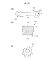
- the power conversion mechanism 35 includes an arm member 36a having one end rotatably connected to the worm wheel 33 and an arm member 36b having one end fixed to the output shaft 37.
- the other ends of the arm member 36a and the arm member 36b are connected to each other. Are connected rotatably by a connecting pin 38.
- the output shaft 37 is rotatably attached to the gear case 31, and a rear wiper arm for wiping the rear window glass is fixed to the end of the output shaft 37 protruding to the outside of the gear case 31.
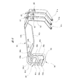
- a connector unit 40 shown in FIGS. 2 to 5 is accommodated in the connector unit accommodating portion 31b of the gear case 31.
- FIG. The connector unit 40 is disposed inside the connector unit housing portion 31b shown in FIG. 1 and is covered with a base (not shown) fixed to the gear case 31 and a plurality of electrical components 60 (shaded portions in the figure). And a connector connecting portion 70 exposed to the outside without being covered by the cover.
- the base part 50 and the connector connecting part 70 are injection-molded integral resin members.
- the connector connecting part 70 is an external connector (not shown) in which a plurality of wires connected to an in-vehicle battery, an in-vehicle controller, and the like are integrated. ) Is connected.
- the electrical component 60 is formed of a conductive steel material or steel plate.
- the electrical component 60 also includes an electronic component (for example, a varistor) for removing brush noise and the like.
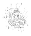
- the base portion 50 is formed in a substantially flat plate shape, and a circular opening 51 through which the armature shaft 24 (FIG. 1) is inserted is provided at the substantially longitudinal center thereof. It has been.
- Three contact plate mounting portions 52a to 52c are formed on one end side in the longitudinal direction of the base portion 50 (the right side in FIG. 2 and the upper side in FIGS. 3 to 5), and each contact plate mounting portion 52a is formed.
- Contact plates 61a to 61c are attached to .about.52c, respectively.
- the contact plate mounting portions 52b and 52c are formed in a groove shape, and the contact plates 61b and 61c are respectively fitted inside the contact plate mounting portions 52b and 52c.
- retaining pieces 62 are appropriately formed on the contact plates 61a to 61c.
- the contact plate mounting portions 52a to 52c are engaged with the retaining pieces 62 formed on the contact plates 61a to 61c, and the contact plates 61a to 61c are removed.
- a retaining protrusion 53 is appropriately formed.
- connection spaces CS1 and CS2 connection spaces (welding spaces) CS1 and CS2, respectively.
- the contact plates 61b and 61c and the jumper wires 63b and 63c are electrically connected in the connection spaces CS1 and CS2, respectively.
- the contact plates 61a to 61c are formed by bending a thin plate made of a brass material having excellent conductivity into a predetermined shape.
- the shapes of the contact plates 61a to 61c are most clearly shown in FIG.
- One end side of each of the contact plates 61a to 61c constitutes a slidable contact arm portion that slidably contacts a switching plate (not shown) mounted on the worm wheel 33 shown in FIG.
- Each slidable arm portion of the contact plates 61a to 61c slides on the switching plate as the worm wheel 33 rotates, and performs a switching operation.
- the wiper switch is turned off, the rear wiper arm is automatically stopped at a predetermined stop position on the rear window glass.
- a connector connecting portion 70 is formed on the opposite side of the opening 51 from the contact plate mounting portions 52a to 52c (the left side in FIG. 2 and the lower side in FIGS. 3 to 5).
- an insertion hole 71 into which an external connector (not shown) is inserted is provided on one side of the connector connecting portion 70.
- the external connector is inserted into the insertion hole 71 from the front side to the back side in FIG. 3, from the right side to the left side in FIG. 4, and from the left side to the right side in FIG. That is, the direction of the arrow X shown in FIGS. 2, 4, and 5 is the direction of insertion into the insertion hole 71 of the external connector.
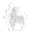
- the connector unit 40 has a plurality of conductive members disposed across the connector connecting portion 70 and the base portion 50. Specifically, a first conductive plate 64 as a first conductive member, a second conductive plate 65 as a second conductive member, and a third conductive plate 66 as a third conductive member are arranged.
- the first conductive plate 64, the second conductive plate 65, and the third conductive plate 66 are inserted in the insertion hole 71 (FIG. 3) of the external connector with respect to the connector connecting portion 70 (
- the connector connecting portion 70 is mounted facing the first direction (arrow Y direction) opposite to the arrow X direction. That is, the mounting direction of the three conductive plates 64, 65, 66 to the connector connecting portion 70 is opposite to the mounting direction (connecting direction) of the external connector to the connector connecting portion 70.
- the three conductive plates 64, 65, 66 are all attached to the connector connecting portion 70 from the same direction.
- a structure for attaching the first conductive plate 64, the second conductive plate 65, and the third conductive plate 66 to the connector connecting portion 70 will be specifically described.
- the bottom of the insertion hole 71 (FIG. 3) into which the external connector is inserted is along the second direction (arrow Z direction) intersecting the first direction (arrow Y direction).
- the three insertion holes 74, 75, 76 are formed in a row. That is, the three insertion holes 74, 75, and 76 are provided at different positions in the second direction (arrow Z direction).
- the conductive plates 64, 65, and 66 are inserted into the insertion holes 74, 75, and 76, respectively, and external connectors inserted into the insertion holes 71 (FIG. 3).
- Connector side connection portions 64a, 65a, 66a that are electrically connected, base side connection portions 64b, 65b, 66b connected to terminals and wires provided in the base portion 50, and connector side connection portions 64a, 65a. , 66a and base side connection portions 64b, 65b, 66b, and intermediate portions 64c, 65c, 66c.
- the connector side connection portion, the base side connection portion, and the intermediate portion in each of the conductive plates 64, 65, 66 are integrally formed. That is, the above distinction is for the convenience of explanation.
- the connector side connection portion 64a of the first conductive plate 64 is inserted into the insertion hole 74 along the first direction (arrow Y direction) and is inserted into the insertion hole 71 (FIG. 3). It protrudes.
- the connector side connection portion 65a of the second conductive plate 65 is inserted into the insertion hole 75 along the first direction (arrow Y direction) and protrudes into the insertion hole 71 (FIG. 3).
- the connector side connection portion 66a of the third conductive plate 66 is inserted into the insertion hole 76 along the first direction (arrow Y direction) and protrudes into the insertion hole 71 (FIG. 3).
- the connector side connection portions 64a, 65a, 66a of the conductive plates 64, 65, 66 projecting into the insertion hole 71 are external connectors inserted into the insertion holes 71, that is, connected to the connector unit 40. In contact with the predetermined terminal and electrically connected to the predetermined terminal. Specifically, the connector side connection portion 64a of the first conductive plate 64 and the connector side connection portion 65a of the second conductive plate 65 are electrically connected to the drive system terminals of the external connector, respectively. Further, the connector side connection portion 66a of the third conductive plate 66 is electrically connected to the control system terminal of the external connector. That is, the first conductive plate 64 and the second conductive plate 65 are drive system conductive members, and the third conductive plate 66 is a control system conductive member.
- the base-side connecting portion 64 b of the first conductive plate 64 is connected to a female terminal 67 that is one of terminals provided on the base portion 50, and this female terminal 67 is electrically connected to the power supply unit 27 (FIG. 1).
- the base-side connection portion 64b of the first conductive plate 64 is also connected to a jumper wire 63c that is one of the wirings provided in the base portion 50, and the jumper wire 63c is connected to the jumper wire 63c. And is electrically connected to the contact plate 61c.
- the base-side connecting portion 65 b of the second conductive plate 65 is connected to a female terminal 68 that is another one of the terminals provided on the base portion 50, and this female
- the power supply unit 27 (FIG. 1) is electrically connected via a mold terminal 68.
- the base-side connecting portion 66b of the third conductive plate 66 is connected to a jumper line 63b, which is another wiring provided in the base portion 50, and the jumper wire 63b is used for this connection.
- the contact plate 61b is electrically connected. Note that no conductive plate is connected to the contact plate 61a.
- the jumper wires 63b and 63c are formed by bending a conductive wire having a circular cross section having a predetermined length along a jumper wire mounting groove formed in the base portion 50.
- a plurality of locking claws are appropriately formed in the jumper wire mounting groove, and the jumper wires 63b and 63c mounted in the jumper wire mounting groove are held by the locking claws at a plurality of locations in the longitudinal direction.
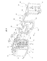
- the intermediate portions 64c, 65c, 66c of the respective conductive plates 64, 65, 66 are placed on the side surface of the connector connecting portion 70 and the side surface of the base portion 50 connected to the side surface.
- the first mounting portion 81, the second mounting portion 82, and the third mounting portion 83 are formed in a step shape.
- the intermediate portions 64c, 65c, 66c of the respective conductive plates 64, 65, 66 include flat portions 64c1, 65c1, 66c1 parallel to the base side connection portions 64b, 65b, 66b, respectively (FIG. 6). See also).
- the flat portion 64c1 of the intermediate portion 64c of the first conductive plate 64 is placed on the first mounting portion 81, and the flat portion 65c1 of the intermediate portion 65c of the second conductive plate 65 is mounted. Is mounted on the second mounting portion 82, and the flat portion 66c1 of the intermediate portion 66c of the third conductive plate 66 is mounted on the third mounting portion 83, respectively.
- the first mounting portion 81 rises from the first support surface 81a on which the lower surface of the flat portion 64c1 is placed and the edge of the first support surface 81a, and the side surface of the flat portion 64c1 abuts. And the first positioning surface 81b.
- the second mounting portion 82 includes a second support surface 82a on which the lower surface of the flat portion 65c1 is placed, and a second positioning surface 82b that rises from the edge of the second support surface 82a and abuts against the side surface of the flat portion 65c1. It is configured.
- the third mounting portion 83 includes a third support surface 83a on which the lower surface of the flat portion 66c1 is placed, and a third positioning surface 83b that rises from the edge of the third support surface 83a and abuts the side surface of the flat portion 66c1. It is configured.
- the second support surface 82a of the second mounting portion 82 extends in parallel to the first support surface 81a from the edge of the first positioning surface 81b of the first mounting portion 81.
- the third support surface 83a of the third mounting portion 83 extends in parallel to the second support surface 82a from the edge of the second positioning surface 82b of the second mounting portion 82. That is, the 1st mounting part 81, the 2nd mounting part 82, and the 3rd mounting part 83 are formed in step shape along the 2nd direction (arrow Z direction).
- the flat portion 65c1 of the second conductive plate 65 placed on the second conductive plate 65 and the flat portion 66c1 of the third conductive plate 66 placed on the third mounting portion 83 (third support surface 83a) are in the second direction (arrows). (Z direction) are arranged at different positions.
- the base side connection portions 64b, 65b, 66b of the conductive plates 64, 65, 66 are arranged at the same position in the second direction (arrow Z direction).
- the flat portions 64c1, 65c1, 66c1 are arranged at different heights in the plane of FIG. 10, and the base side connection portions 64b, 65b, 66b are arranged at the same height.
- the conductive plates 64, 65, and 66 are hatched (hatched).
- the hatching indicates a cross section. is not.
- positioning condition of each electroconductive board 64,65,66 can be understood more clearly by referring FIG. 7, FIG. 8 collectively.
- a holder member 90 is attached to the connector connecting portion 70 of the connector unit 40. As shown in FIG. 9, the holder member 90 faces the bottom outer surface (the bottom surface of the connector connecting portion 70) of the insertion hole 71 (FIG. 3) into which the external connector is inserted from the first direction (arrow Y direction). It is attached to the connector connecting portion 70. That is, the holder member 90 is attached to the connector connecting portion 70 facing the connector connecting portion 70 from the same direction as the conductive plates 64, 65, 66. The holder member 90 attached to the connector connection portion 70 holds the conductive plates 64, 65, 66 with the connector connection portion 70.
- the holder member 90 extends in a direction substantially orthogonal to the main wall portion 91 from the main wall portion 91 facing the bottom surface of the connector connection portion 70, and one longitudinal end of the main wall portion 91. And a side wall 92.
- three engagement claws 93 that are respectively inserted into three engagement holes 77 (FIG. 9) provided on the bottom surface of the connector connection portion 70 are integrally formed.
- an insertion protrusion 94 to be inserted into a through hole 78 (FIG. 9) provided on the bottom surface of the connector connection portion 70 is also integrally formed on the inner surface of the main wall portion 91.
- the three engaging claws 93 penetrate the predetermined engaging holes 77 and enter the inside of the insertion holes 71 (FIG. 3), and engage around the engaging holes 77.
- the holder member 90 is securely fixed at an accurate position on the connector connecting portion 70.
- the conductive plates 64, 65, 66 held between the connector connecting portion 70 and the holder member 90 are also accurate. Securely fixed in position. In other words, the conductive plates 64, 65, 66 and the holder member 90 are surely prevented from falling off or being displaced.
- an insulating protrusion 95 having a predetermined shape is integrally formed on the inner surface of the main wall portion 91 of the holder member 90.
- An insulating protrusion 95 provided on the holder member 90 enters between the adjacent first conductive plate 64 and the second conductive plate 65 and is interposed. Thereby, the insulation between the 1st conductive plate 64 and the 2nd conductive plate 65 is ensured still more reliably.
- the side wall 92 of the holder member 90 includes a first mounting portion 81, a second mounting portion 82, and a third mounting portion 83 that are formed in a step shape. It is formed in a staircase shape according to. Accordingly, the flat portion 64c1 of the first conductive plate 64, the flat portion 65c1 of the second conductive plate 65, and the flat portion 66c1 of the third conductive plate 66 that are arranged at different positions in the second direction (the arrow Z direction). Since the side wall part 92 of the holder member 90 is arrange
- the first conductive plate 64, the second conductive plate 65, and the third conductive plate 66 all face the connector connecting portion 70 from the same direction (first direction / arrow Y direction). It is mounted (see FIG. 9). Further, the base side connection portions 64b, 65b, 66b of the first conductive plate 64, the second conductive plate 65, and the third conductive plate 66 are in a state in which these conductive plates 64, 65, 66 are attached to the connector connection portion 70.
- the three conductive plates 64, 65, 66 are attached to the connector connecting portion 70 in order from the conductive plate disposed at the innermost position in the first direction (arrow Y direction). That is, as shown in FIG. 9, the third conductive plate 66 is mounted first, and then the second conductive plate 65 and the first conductive plate 64 are mounted in this order. Specifically, the connector side connection portion 66 a of the third conductive plate 66 is inserted into the insertion hole 76 provided in the connector connection portion 70.
- the connector-side connecting portion 66a of the third conductive plate 66 is inserted into the insertion hole 76 until a part of the intermediate portion 66c (flat portion 66c1) hits the third positioning surface 83b of the third mounting portion 83. . That is, the third conductive plate 66 is positioned by the third positioning surface 83 b of the third mounting portion 83. The other part of the intermediate portion 66c of the third conductive plate 66 is fitted into a holding groove 79 formed along the arrangement direction of the insertion holes 74, 75, and 76.
- the connector side connection portion 65 a of the second conductive plate 65 is inserted into the insertion hole 75 provided in the connector connection portion 70.
- the connector side connection portion 65a of the second conductive plate 65 is inserted into the insertion hole 75 until a part of the intermediate portion 65c (flat portion 65c1) hits the second positioning surface 82b of the second mounting portion 82. . That is, the second conductive plate 65 is positioned by the second positioning surface 82b of the second mounting portion 82.
- the connector side connection portion 64 a of the first conductive plate 64 is inserted into the insertion hole 74 provided in the connector connection portion 70.
- the connector side connection portion 64a of the first conductive plate 64 is inserted into the insertion hole 74 until a part of the intermediate portion 64c (flat portion 64c1) hits the first positioning surface 81b of the first mounting portion 81. . That is, the first conductive plate 64 is positioned by the first positioning surface 81 b of the first mounting portion 81.
- all of the conductive plates 64, 65, 66 are in the same direction (first direction / It is attached to the connector connecting portion 70 from the direction of arrow Y). That is, all of the plurality of conductive plates 64, 65, 66 that are three-dimensionally bent are attached to the connector connection portion 70 without using insert molding, and all of the plurality of conductive plates 64, 65, 66 are in the same direction. Since it is attached to the connector connecting portion 70, the attachment process (assembly process) of the conductive plates 64, 65, 66 is simplified. Further, since the positioning surfaces 81b, 82b and 83b corresponding to the respective conductive plates 64, 65 and 66 are prepared, the assembling property of the conductive plates 64, 65 and 66 is also improved.
- the holder member 90 is attached to the connector connecting portion 70 to which the conductive plates 64, 65, 66 are attached as described above.
- the holder member 90 faces the connector connecting portion 70 from the same direction as the mounting direction of the conductive plates 64, 65, 66 to the connector connecting portion 70, that is, the first direction (arrow Y direction), and is attached to the connector connecting portion 70. Is done. That is, all of the plurality of conductive plates 64, 65, 66 and the holder member 90 are attached to the connector connecting portion 70 from the same direction.
- the mounting process (assembly process) of the conductive plates 64, 65, 66 and the holder member 90 to the connector connecting portion 70 is simplified, and the simplification of the manufacturing process of the wiper motor 10 and the miniaturization of the wiper motor 10 are realized.
- the mounting directions of the plurality of conductive plates 64, 65, 66 and the holder member 90 to the connector connecting portion 70 are common, the assembly process of the conductive plates 64, 65, 66 and the holder member 90 can be easily automated.
- the connector unit accommodating portion for accommodating the connector unit is provided in the gear case.
- the connector unit accommodating portion is provided at the opening end of the yoke, and the connector unit is accommodated in the connector unit accommodating portion. You can also
- the number of conductive members is not limited to three, and a necessary number of conductive members can be provided according to the specifications (functions) of the motor device.
- insertion holes and mounting portions provided in the connector connecting portion are appropriately increased according to the number of conductive members.
- the present invention can be applied not only to a rear wiper motor but also to a drive source of a vehicle front wiper device or a drive source of a device other than a wiper device.
- FIG. 14 is a plan view of the wiper motor according to the second embodiment
- FIG. 15 is a partial sectional view taken along the line AA in FIG. 14
- FIG. 16 is a view of the connector unit and the worm wheel as viewed from the back side of FIG.
- FIG. 17 is a perspective view of the connector unit as seen from the speed reduction mechanism side
- FIG. 18 is a partially enlarged view comparing the switching plate of the second embodiment and the switching plate of the comparative example.
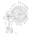
- a wiper motor 110 as a motor device is used as a drive source of a rear wiper device (not shown) mounted on a rear hatch of a vehicle, and includes a motor unit 120 and a speed reduction mechanism unit 130. .
- the motor unit 120 and the speed reduction mechanism unit 130 are coupled together by a pair of fastening screws 111.
- the wiper motor 110 is disposed in a narrow space such as a rear hatch, and reciprocates (oscillates) a wiper blade (not shown) provided on a rear glass (not shown) within a predetermined angle range.
- the motor unit 120 is configured as a brushed four-pole motor.
- the motor unit 120 includes a motor case 121, and the motor case 121 is formed into a bottomed cylindrical shape by deep drawing a steel plate that is a magnetic body.
- the motor case 121 includes a pair of arc portions 121a and a pair of straight portions 121b, and the arc portions 121a and the straight portions 121b are disposed to face each other with the axis (armature shaft 124) of the motor case 121 interposed therebetween. .
- the cross-sectional shape of the motor case 121 is formed in a substantially oval shape. Therefore, the width of the motor case 121, that is, the thickness dimension in the left-right direction in FIG.
- Each arc part 121a and each linear part 121b are extended from the opening part side of the motor case 121 to the bottom part side.
- the motor case 121 has a straight shape without a stepped portion, and as a result, the ease of deep drawing of the motor case 121 is improved.
- the brush holder 170 since the brush holder 170 does not enter the opening side of the motor case 121, the axial length of the motor case 121 is also suppressed.
- the motor case 121 is formed in an advantageous shape from the viewpoint of improving the moldability and reducing the size and weight.
- each magnet 122 is, for example, a ferrite magnet, and is fixed at equal intervals (90-degree intervals) along the circumferential direction of the motor case 121.
- an armature 123 is interposed via a predetermined gap. It is housed rotatably. At the rotation center of the armature 123, the proximal end side of the armature shaft (rotating shaft) 124 is fixed through.
- a commutator 125 is fixed to a substantially central portion along the axial direction of the armature shaft 124, and the commutator 125 includes ten segments 125a.
- An armature core 126 that forms the armature 123 is fixed to the base end side of the armature shaft 124, and the armature core 126 includes ten teeth 126a. Slots are formed between the teeth 126a.
- Each tooth 126a is wound with a plurality of armature coils 126b with a predetermined winding method and a predetermined number of turns. The coil end of each armature coil 126b is electrically connected to each segment 125a.
- a plurality of power supply brushes 125b are in sliding contact with each segment 125a of the commutator 125.
- Each power supply brush 125b is movably provided on a brush holder 170 accommodated in a brush holder accommodating portion 134 of the housing 131, and a drive current from the connector unit 150 is supplied to each power supply brush 125b.
- the motor unit 120 and the connector unit 150 are electrically connected via the respective power supply brushes 125b, the commutator 125, and the armature coil 126b, whereby an electromagnetic force is generated in the armature coil 126b, and the armature 123 (armature The shaft 124) rotates.
- the power supply brush 125b and the brush holder 170 are not shown for easy understanding.
- the base end side of the armature shaft 124 is rotatably accommodated in the motor case 121 and is supported only by a radial bearing 127 provided on the bottom side of the motor case 121.
- a thrust bearing that supports the armature shaft 124 from the axial direction is not provided between the base end side of the armature shaft 124 and the motor case 121.
- the radial bearing 127 is formed in a substantially cylindrical shape by, for example, a sintered material, thereby having low noise, impact resistance, and self-lubricating property, and further, it is difficult for abrasion powder to be generated.
- the radial bearing 127 can be formed of a plastic material having excellent heat resistance instead of the sintered material.
- a worm gear 124 a (not shown in detail) is integrally provided on the distal end side of the armature shaft 124, and the worm gear 124 a rotates in the housing 131 as the armature shaft 124 rotates.
- the worm gear 124 a is formed in a spiral shape and meshed with the gear teeth 132 a of the worm wheel 132.
- the worm gear 124a and the worm wheel 132 constitute a reduction mechanism in the present invention.
- the worm gear 124a rotates, the worm wheel 132 rotates in a decelerating state than the worm gear 124a, and outputs the rotation reduced and increased in torque to the outside.
- the inner ring member 128a of the ball bearing 128 is fixed by press fitting. Further, the outer ring member 128 b of the ball bearing 128 is sandwiched between the housing 131 and the stopper plate 160. As a result, the armature shaft 124 is rotatably supported by the ball bearing 128 and the movement in the axial direction and the radial direction with respect to the housing 131 is restricted. As described above, the ball bearing 128 has a function as a radial bearing and a thrust bearing. Therefore, a thrust bearing that supports the armature shaft 124 from the axial direction is not provided between the distal end side of the armature shaft 124 and the housing 131.
- the wiper motor 110 is configured as a small and light four-pole motor, the amount of heat generated is larger than that of a large two-pole motor having the same output, for example.
- thrust bearings are not provided at both ends of the armature shaft 124 in the axial direction, the sliding loss of the armature shaft 124, that is, frictional resistance with the thrust bearing is eliminated, and an excessive increase in heat generation is prevented. Like to do.
- the speed reduction mechanism unit 130 includes a housing 131 formed in a substantially bathtub shape by casting a molten aluminum material or the like.
- the housing 131 includes a bottom portion 131a and a wall portion 131b, and an opening portion 131c is formed on the side opposite to the bottom portion 131a side.
- the opening 131c is closed by a gear cover (not shown), and the worm wheel 132, the connector unit 150, and the like are accommodated in the housing 131 from the opening 131c.
- a brush holder housing part 134 is integrally provided on the motor part 120 side of the housing 131.
- the brush holder housing part 134 is formed in a cylindrical shape so as to extend along the axial direction of the armature shaft 124, and its cross-sectional shape is substantially oval, similar to the cross-sectional shape of the motor case 121 (see FIG. 15). Is formed.
- a worm wheel (rotating body) 132 shown in FIG. 16 is rotatably provided inside the housing 131, and the worm wheel 132 is formed in a substantially disk shape by injection molding a resin material such as plastic. .
- Gear teeth 132a are integrally provided on the outer peripheral portion of the worm wheel 132, and the worm gear 124a (see FIG. 14) is engaged with the gear teeth 132a.
- a wheel shaft 132b made of a steel rod having a circular cross section is fixed, and the other axial end side of the wheel shaft 132b is provided on the bottom 131a of the housing 131.
- a boss (not shown) is rotatably supported.
- a pair of outer peripheral engagement holes 132c are provided on the worm wheel 132 closer to the gear teeth 132a than the wheel shaft 132b.
- a pair of inner peripheral engagement holes 132d facing each other so as to sandwich the wheel shaft 132b are provided closer to the wheel shaft 132b than the gear teeth 132a of the worm wheel 132.
- the outer peripheral engagement holes 132c and the inner peripheral engagement holes 132d are disposed at positions that are relatively rotated by about 90 ° around the axis of the wheel shaft 132b.
- the fixing claws 133c and 133d for fixing the switching plate 133 to the worm wheel 132 are respectively inserted and attached. Accordingly, the outer peripheral portion 133a and the inner peripheral portion 133b of the switching plate 133 can be firmly fixed without rattling with respect to the worm wheel 132.
- a switching plate made of a conductive steel plate is provided as shown by the hatched portion in FIG.
- the switching plate 33 is formed of brass or the like having excellent conductivity, and is formed in a substantially annular shape by performing press processing (such as punching processing).
- each outer peripheral side fixed claw 133c and each inner peripheral side fixed claw 133d are arranged at positions that are relatively rotated by about 90 ° around the axis of the wheel shaft 132b.
- a part of the outer periphery 133 a of the switching plate 133 is provided with a recess 133 e that is recessed inward in the radial direction of the switching plate 133. Further, a part of the inner peripheral portion 133 b of the switching plate 133 is provided with a convex portion 133 f that protrudes radially inward of the switching plate 133. Furthermore, an annular plate body 133g that does not have irregularities or the like is provided between the outer peripheral portion 133a and the inner peripheral portion 133b along the radial direction of the switching plate 133.
- a portion of the switching plate 133 corresponding to the plate main body 133g, a portion corresponding to the concave portion 133e, and a portion corresponding to the convex portion 133f are respectively provided with a first sliding contact portion 133h and a second sliding portion extending in the circumferential direction of the switching plate 133.
- a sliding contact portion 133i and a third sliding contact portion 133j are formed.
- tip portions of the first contact plate CP1 and the second contact plate CP2 provided in the connector unit 150 as the worm wheel 132 rotates. Are in sliding contact with each other.
- the present embodiment has a structure that does not have a function of generating a back electromotive force in the motor unit 120 and applying a brake.
- the third sliding contact portion 133j corresponding to the convex portion 133f is provided, when a braking function by a counter electromotive force is required, a connector unit that can exhibit the function, that is, the first to third contacts It can be easily handled by simply replacing the connector unit with a plate.
- An electric circuit (not shown) in which a closed loop circuit is formed according to the rotational position of the worm wheel 132 is used as an electric circuit that exhibits a braking function based on counter electromotive force.
- the first contact plate CP1 which is slidably in contact with the first slidable contact portion 133h, is slidably in contact with the second slidable contact portion 133i, and is connected to the switching plate 133 by the recess 133e.
- the in-vehicle controller turns off the wiper switch (not shown) by the driver, and the contact plates CP1 and CP2 are in a non-energized state (the second contact plate CP2 reaches the recess 133e).
- the wiper blade can be stopped at a predetermined stop position.
- an output shaft 135 made of a steel rod having a circular cross section is accommodated in a portion (left side in the drawing) of the housing 131 away from the worm wheel 132.
- the output shaft 135 is rotatably supported by a boss portion (not shown) provided on the bottom portion 131 a of the housing 131.
- a base end portion of the wiper blade is fixed to an extended portion (not shown) extending to the outside of the output shaft 135.
- a motion conversion mechanism 140 that converts the rotational motion of the worm wheel 132 into the swing motion of the output shaft 135 is provided between the proximal end side of the output shaft 135 and the worm wheel 132.
- the motion conversion mechanism 140 includes a swing link 141, a connecting plate 142, and a sliding contact plate 143.
- the swing link 141 is formed into a plate shape by punching a steel plate, and one end side in the longitudinal direction of the swing link 141 is fixed to the base end side of the output shaft 135.
- the other end in the longitudinal direction of the swing link 141 is rotatably connected to one end in the longitudinal direction of the connecting plate 142 via the first connecting pin P1.
- the other end in the longitudinal direction of the connecting plate 142 is rotatably connected to a position eccentric from the rotation center of the worm wheel 132 via the second connecting pin P2.
- the length dimension of the swing link 141 is set to be approximately half (approximately 1/2) the length dimension of the connecting plate 142.
- the connecting plate 142 is also formed in a plate shape by punching a steel plate or the like in the same manner as the swing link 141.
- the output shaft 135 can be swung in a predetermined angular range as the worm wheel 132 rotates in one direction. Yes. Specifically, the rotational force reduced and increased in torque by the rotation of the worm gear 124a and the worm wheel 132 is transmitted to the second connecting pin P2, and the second connecting pin P2 rotates about the wheel shaft 132b. Then, the longitudinal direction other end side of the connecting plate 142 also rotates around the wheel shaft 132b, so that the longitudinal end portion of the connecting plate 142 is regulated by the swing link 141 via the first connecting pin P1. Oscillates around the output shaft 135.
- the sliding contact plate 143 is formed in a plate shape from a resin material such as plastic having excellent self-lubricating properties, and is attached to the gear cover side (front side in FIG. 14) of the connecting plate 142.
- a slidable contact portion 143a that is in slidable contact with the gear cover is integrally provided at a central portion in the longitudinal direction of the slidable contact plate 143, and grease (not shown) is applied to the slidable contact portion 143a.
- a connector unit 150 is formed into a predetermined shape by injection molding a resin material such as plastic, and a connector main body 151 formed in a plate shape and a connector formed in a box shape with a bottom. And a connection part 152.
- the connector unit 150 is provided so as to straddle the armature shaft 124, and a through cylinder portion 151 a through which the armature shaft 124 (see FIG. 14) passes is formed at a substantially central portion of the connector main body portion 151.
- the inner diameter dimension of the through cylinder 151a is set to be slightly larger than the outer diameter dimension of the ball bearing 128 (see FIG. 14).
- a connector connecting portion 152 is arranged on one side of the connector main body 151 sandwiching the armature shaft 124 (right side in FIG. 17).
- a contact plate support 151b is integrally provided on the other side (left side in FIG. 17) across the armature shaft 124 of the connector main body 151, and the contact plate support 151b is formed from the surface 151c of the connector main body 151. It protrudes in the axial direction of the armature shaft 124.
- a first contact plate CP1 and a second contact plate CP2 for switching the energization state to the motor unit 120 are arranged in parallel with the contact plate support 151b so as to be aligned in the radial direction of the armature shaft 124. It is installed.
- Each of these contact plates CP1 and CP2 is inserted and fixed from one side (the lower side in FIG. 17) of the connector main body 151 in the short direction.
- the first contact plate CP1 is always in sliding contact with the switching plate 133 regardless of the rotational position of the worm wheel 132, and is disposed on the side opposite to the connector connecting portion 152 side of the connector unit 150.
- the second contact plate CP2 passes through the recess 133e of the switching plate 133 with the rotation of the worm wheel 132, and is disposed near the connector connecting portion 152 of the connector unit 150.
- each jumper line JP1, JP2 is between each contact plate CP1, CP2 and the base end side of each male terminal TM1 and the base end side of each female terminal TM2 provided on the connector connecting portion 152 side.
- a plurality of male terminals TM1 and female terminals TM2 are provided on the connector connecting portion 152 side.
- a vehicle-side external connector (not shown) connected to the connector connecting portion 152 is electrically connected to the distal end side of each male terminal TM1, and a brush holder 170 is disposed on the distal end side of each female terminal TM2.
- Each male terminal (not shown) provided in is inserted and connected.
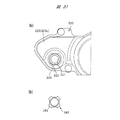
- the connector unit 150 does not include an electric circuit that exhibits a braking function based on the counter electromotive force, and includes only the first contact plate CP1 and the second contact plate CP2. . Therefore, as shown in FIG. 16, the width dimension W of the connector unit 150 is shortened, so that the wiper motor 110 is reduced in size and weight.
- the 3rd contact plate (not shown) which exhibits the brake function by back electromotive force, since it is necessary to make the said 3rd contact plate slidably contact with the 3rd slidable contact part 133j, The width dimension increases.
- the second contact plate CP2 reaches the recess 133e, the supply of the drive current to the motor unit 120 is stopped and the wiper motor 110 is stopped.
- the worm wheel 132 is rotated by inertia, and the second contact plate CP2 advances through the recess 133e by the distance L1 and is stopped at the stop point SP.
- the wiper blade is stopped at a predetermined stop position.
- the distance L1 that the second contact plate CP2 travels in the recess 133e by inertia is, for example, 3.0 mm, and the rotation angle of the worm wheel 132 is ⁇ ° (about 12 °).
- the stop position accuracy can be worse in the comparative example than in the second embodiment. is doing.
- the recesses 133e and b are formed in the same angular range ⁇ ° of the worm wheels 132 and d, and the length dimension along the circumferential direction of the recess 133e.
- L2 (Embodiment 2) can be set to a length longer than the length L3 (comparative example) along the circumferential direction of the recess b (L2> L3).
- the second contact plate CP2 is not rotated beyond the recess 133e in the second embodiment, and the wiper motor 110 is reliably stopped. be able to.
- the second contact plate may exceed the recess b, so that a braking function by back electromotive force is necessary.
- the recess 133e through which the second contact plate CP2 passes as the worm wheel 132 rotates is provided in a part of the outer peripheral portion 133a of the switching plate 133. Therefore, the rotation angle ⁇ ° of the worm wheel 132 can be reduced with respect to the distance L1 (for example, 3.0 mm) by which the second contact plate CP2 travels in the recess 133e with inertia, and as a result, the worm wheel 132 can be compared with the comparative example. Variations are less likely to occur at the stop position of the wheel 132. This makes it possible to improve the stop position accuracy of the worm wheel 132 as well as reducing the size and weight of the wiper motor 110 and reducing the cost.
- L1 for example, 3.0 mm
- the wiper motor 110 since the convex portion 133f that protrudes radially inward of the switching plate 133 is provided on a part of the inner peripheral portion 133b of the switching plate 133, the motor portion 120 A function of generating a counter electromotive force and applying a brake can be added to meet various needs.
- the concave portion 133e is formed on a part of the outer peripheral portion 133a of the switching plate 133, a convex portion is formed on a part of the outer peripheral portion of the switching plate of the comparative example. Compared to (see FIG. 18B), it is possible to suppress the generation of useless portions of the base material (material) of the switching plate and improve the yield.
- FIG. 19 is a plan view showing the speed reduction mechanism of the wiper motor according to the third embodiment.
- the wiper motor (motor device) 180 has a position of the output shaft 135 and the motion conversion mechanism 190 of the wiper motor 110 (see FIG. 14) according to the second embodiment.
- the structure is different.
- the output shaft 135 of the wiper motor 180 is disposed on the side opposite to the armature shaft 124 side with the worm wheel 132 of the housing 181 interposed therebetween. Thereby, in the wiper motor 180, the dimension along the axial direction of the armature shaft 124 can be reduced as compared with the second embodiment.
- the motion conversion mechanism 190 of the wiper motor 180 includes a pinion gear 191, a motion conversion member 192, a connecting plate 142, and a sliding contact plate 143.
- the pinion gear 191 is fixed to the proximal end side of the output shaft 135 and swings with the output shaft 135.
- the motion conversion member 192 includes a sector gear 192a that meshes with the pinion gear 191 and an arm portion 192b that is rotatably connected to the eccentric position of the worm wheel 132 via the second connection pin P2.
- a first connecting pin P1 is provided at the center of the sector gear 192a, and a connecting plate 142 is provided between the first connecting pin P1 and the output shaft 135.
- one end in the longitudinal direction of the connecting plate 142 is rotatably connected to the proximal end of the output shaft 135, and the other end in the longitudinal direction of the connecting plate 142 is rotatably connected to the first connecting pin P1.
- the connecting plate 142 keeps the distance between the output shaft 135 and the first connecting pin P1 constant, and maintains the engagement between the pinion gear 191 and the sector gear 192a.
- the rotational motion of the worm wheel 132 is converted into the swing motion of the output shaft 135.
- the arm portion 192b of the motion conversion member 192 also rotates around the wheel shaft 132b.
- the sector gear 192a swings about the first connecting pin P1
- the pinion gear 191 that meshes with the sector gear 192a, that is, the output shaft 135 swings.
- the wiper motor 180 according to the third embodiment can achieve the same functions and effects as those of the second embodiment described above.
- the present invention is not limited to the above-described embodiment, and various modifications can be made without departing from the scope of the invention.
- the cross-sectional shapes of the motor case 121 and the brush holder accommodating portion 134 are each formed in a substantially oval shape.
- the present invention is not limited to this, for example, an oval shape. It can also be formed in a rectangular shape.
- the reduction gear mechanism including the worm gear 124a and the worm wheel 132 is used.
- the present invention is not limited to this, and for example, a planetary gear reduction gear is used as the reduction gear mechanism. It can also be adopted.
- the sun gear may be an input side (armature shaft 124 side) gear and the ring gear may be an output side (output shaft 135 side) gear.
- a ferrite magnet is used as each magnet 122.
- the present invention is not limited to this, and a plate magnet made of a neodymium magnet or the like can also be used.
- the number of magnets, the number of segments, the number of teeth, etc. may be freely set according to the specifications required for the motor unit.
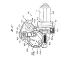
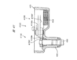
- FIG. 20 is a plan view of the wiper motor according to the fourth embodiment
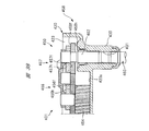
- FIG. 21 is a partial sectional view taken along the line AA in FIG. 20
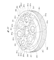
- FIG. 22 is a perspective view of the worm wheel alone viewed from the front side
- FIG. 24 is a perspective view of the worm wheel as viewed from the back side
- FIG. 24 is a partially enlarged view for explaining the positional relationship between the coupling portion, the gear portion-side recess, and the wheel shaft fixing hole-side recess
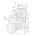
- FIG. 25 is the first cylindrical portion
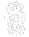
- FIG. 26 shows a view of the connector unit and the worm wheel as seen from the back side of FIG. 20.
- a wiper motor 210 as a motor device is used as a drive source for a rear wiper device (not shown) mounted on a rear hatch of a vehicle, and includes a motor unit 220 and a speed reduction mechanism unit 230. .
- the motor unit 220 and the speed reduction mechanism unit 230 are coupled together by a pair of fastening screws 211.
- the wiper motor 210 is disposed in a narrow space such as a rear hatch, and reciprocates (oscillates) a wiper blade (not shown) provided on a rear glass (not shown) within a predetermined angle range.
- the motor unit 220 is configured as a brushed four-pole motor.
- the motor unit 220 includes a motor case 221, and the motor case 221 is formed in a bottomed cylindrical shape by deep drawing a steel plate that is a magnetic material.
- the motor case 221 includes a pair of arc portions 221a and a pair of linear portions 221b, and the arc portions 221a and the linear portions 221b are arranged to face each other across the center (armature shaft 224) of the motor case 221.
- the cross-sectional shape of the motor case 221 is formed in a substantially oval shape. Therefore, the width of the motor case 221, that is, the thickness dimension in the left-right direction in FIG.
- Each arc portion 221a and each linear portion 221b extend from the opening side of the motor case 221 to the bottom side.
- the motor case 221 has a straight shape without a stepped portion, and as a result, the ease of deep drawing of the motor case 221 is improved.
- the motor case 221 is formed in an advantageous shape from the viewpoint of improving moldability and reducing the size and weight.
- each magnet 222 is a ferrite magnet, for example, and is fixed at equal intervals (90 degree intervals) along the circumferential direction of the motor case 221, and the armature 223 is disposed inside each magnet 222 via a predetermined gap. It is housed rotatably. At the rotation center of the armature 223, the base end side of the armature shaft (rotation shaft) 224 is fixed through.
- a commutator 225 is fixed to a substantially central portion along the axial direction of the armature shaft 224, and the commutator 225 includes ten segments 225a.
- An armature core 226 that forms the armature 223 is fixed to the base end side of the armature shaft 224, and the armature core 226 includes ten teeth 226a. Slots are formed between the teeth 226a.
- Each tooth 226a is wound with a plurality of armature coils 226b with a predetermined winding method and a predetermined number of turns. The coil end of each armature coil 226b is electrically connected to each segment 225a.
- a plurality of power supply brushes 225b are in sliding contact with each segment 225a of the commutator 225.
- Each power supply brush 225b is movably provided in a brush holder 270 accommodated in a brush holder accommodating portion 234 of the housing 231, and a drive current from the connector unit 250 is supplied to each power supply brush 225b.
- the motor unit 220 and the connector unit 250 are electrically connected to each other through the power supply brushes 225b, the commutator 225, and the armature coil 226b, whereby an electromagnetic force is generated in the armature coil 226b, and the armature 223 (armature The shaft 224) rotates.
- the power supply brushes 225b and the brush holder 270 are not shown for easy understanding.
- the base end side of the armature shaft 224 is rotatably accommodated in the motor case 221 and is supported only by the radial bearing 227 provided on the bottom side of the motor case 221.
- a thrust bearing that supports the armature shaft 224 from its axial direction is not provided between the base end side of the armature shaft 224 and the motor case 221.
- the radial bearing 227 is formed in a substantially cylindrical shape by, for example, a sintered material, thereby having low noise, impact resistance, and self-lubricating property, and further, abrasion powder is hardly generated.
- the radial bearing 227 can be formed of a plastic material having excellent heat resistance instead of the sintered material.
- a worm gear 224 a (not shown in detail) is integrally provided on the distal end side of the armature shaft 224, and the worm gear 224 a rotates within the housing 231 as the armature shaft 224 rotates.
- the worm gear 224a is formed in a spiral shape and meshed with the gear teeth 280a of the worm wheel 280.
- the worm gear 224a and the worm wheel 280 form a speed reduction mechanism.
- the worm gear 224a rotates, the worm wheel 280 is rotated in a reduced state than the worm gear 224a, and outputs the reduced rotation and increased torque to the outside.
- the inner ring member 228a of the ball bearing 228 is fixed by press fitting. Further, the outer ring member 228 b of the ball bearing 228 is sandwiched between the housing 231 and the stopper plate 260.
- the armature shaft 224 is rotatably supported by the ball bearing 228 and the movement in the axial direction and the radial direction with respect to the housing 231 is restricted.
- the ball bearing 228 has a function as a radial bearing and a thrust bearing. Therefore, a thrust bearing that supports the armature shaft 224 from its axial direction is not provided between the distal end side of the armature shaft 224 and the housing 231.
- the wiper motor 210 is configured as a small and light four-pole motor, the amount of heat generated is larger than that of a large two-pole motor having the same output, for example.
- thrust bearings are not provided at both ends of the armature shaft 224 in the axial direction, the sliding loss of the armature shaft 224, that is, frictional resistance with the thrust bearing is eliminated, and an increase in the amount of heat generated is prevented. Like to do.
- the speed reduction mechanism section 230 includes a housing 231 formed in a substantially bathtub shape by casting a molten aluminum material or the like.
- the housing 231 includes a bottom portion 231a and a wall portion 231b, and an opening portion 231c is provided on the side opposite to the bottom portion 231a side.
- the opening 231c is closed by a gear cover (not shown), and the worm wheel 280, the connector unit 250, and the like are accommodated in the housing 231 from the opening 231c.
- a brush holder accommodating portion 234 is integrally provided on the motor portion 220 side of the housing 231.
- the brush holder accommodating portion 234 is formed in a cylindrical shape so as to extend along the axial direction of the armature shaft 224, and its cross-sectional shape is substantially oval, similar to the cross-sectional shape of the motor case 221 (see FIG. 21). Is formed.
- a worm wheel 280 as a rotating body is rotatably accommodated in the housing 231, and the worm wheel 280 is substantially formed by injection molding a resin material such as plastic. It is formed in a disk shape.
- the worm wheel 280 includes a main body portion 281 and a gear portion 282 having a diameter larger than that of the main body portion 281 and a reduced axial dimension.
- Gear teeth 280a are integrally formed on the outer peripheral portion of the gear portion 282, and a worm gear 224a (see FIG. 20) is engaged with the gear teeth 280a.
- a wheel shaft fixing hole 281a is provided at the rotation center of the main body 281.
- One end of the wheel shaft 280b (see FIG. 20) made of a steel rod having a circular cross section is fixed to the wheel shaft fixing hole 281a.
- the other axial end side of the wheel shaft 280b is rotatably supported by a boss portion (not shown) provided on the bottom portion 231a of the housing 231.
- first recesses 281b that are recessed in the axial direction of the main body 281 are formed around the one side in the axial direction and the other side in the axial direction of the wheel shaft fixing hole 281a.
- Each first recess 281b functions as so-called “meat stealing” and suppresses the occurrence of sink marks and warpage around the wheel shaft fixing hole 281a in the main body portion 281 to improve the molding accuracy of the wheel shaft fixing hole 281a. ing. Thereby, the worm wheel 280 can rotate smoothly without being distorted, and the operation noise of the wiper motor 210 is reduced.
- a pair of connecting portions 281c having insertion holes 281c1 are provided on one side of the main body portion 281 in the axial direction.
- a connecting pin 283 (see FIGS. 20 and 25) to which one side (right side in FIG. 20) of the motion conversion mechanism 240 driven in accordance with the rotation of the worm wheel 280 is connected to any one of the insertion holes 281c1. It is designed to be plugged in. That is, the connection pin 283 is attached to one of the connection portions 281c.
- Each connecting portion 281c is arranged at a position spaced from the wheel shaft fixing hole 281a, which is the rotation center of the worm wheel 280, so as to face each other with the wheel shaft fixing hole 281a interposed therebetween.
- Each connecting portion 281 c is provided near the gear portion 282 on the radially outer side of the main body portion 281.
- the mounting position of the connecting pin 283 can be changed to either one or the other of the connecting portions 281c, in order to cope with various specifications of the wiper motor 210.
- the stop position of the wiper blade is directed to the right, and when mounted on either of the connecting portions 281c, the stop position of the wiper blade is set.
- the worm wheel 280 is formed in a shape that allows the common use of parts, and contributes to a reduction in the manufacturing cost of the wiper motor 210.
- the connecting portion 281c includes a first tubular portion 281d disposed on the radially inner side and a second tubular portion 281e disposed on the radially outer side.
- first tubular portion 281d disposed on the radially inner side
- second tubular portion 281e disposed on the radially outer side.
- the first cylindrical portion 281d is configured to rotatably support the connecting pin 283, and its axial dimension is set to L1.
- the second cylindrical portion 281e is provided around the first cylindrical portion 281d so as to partially reinforce the first cylindrical portion 281d, and the axial dimension thereof is the first cylindrical shape.
- the axial dimension L2 is shorter than the portion 281d (L2 ⁇ L1).
- the second tubular portion 281e partially reinforces the support portion P that supports the connecting pin 283 of the first tubular portion 281d, and thereby supports the connecting pin 283 of the connecting portion 281c.
- the rigidity of the part is made sufficient.
- the axial dimension L1 of the first cylindrical part 281d is set to be longer than the axial dimension L2 of the second cylindrical part 281e, one axial side (the upper side in the figure) of the second cylindrical part 281e.
- a stepped step portion 281f is formed in the step. That is, in the portion corresponding to the stepped portion 281f of the connecting portion 281c, the thickness dimension along the radial direction (corresponding to the thickness dimension of the first cylindrical portion 281d) is reduced to reduce sink marks or warpage when the connecting portion 281c is formed. Etc. can be suppressed.
- a large-diameter hole 281g serving as a second recess is provided on one side (upper side in the figure) of the main body 281 that sandwiches the line segment LN formed by connecting the centers C of the connecting portions 281c.
- One small-diameter hole portion 281h having a smaller diameter than the large-diameter hole portion 281g is provided.
- one large-diameter hole 281g and one small-diameter hole 281h are provided as the second recesses on the other side (lower side in the drawing) of the main body 281 sandwiching the line segment LN.
- the pair of large-diameter hole portions 281g are disposed to face each other with the wheel shaft fixing hole 281a interposed therebetween, and the pair of small-diameter hole portions 281h are also disposed to face each other with the wheel shaft fixing hole 281a interposed therebetween.
- the large-diameter hole 281g and the small-diameter hole 281h that are recessed in the axial direction of the main body 281 are respectively provided on one side of the main body 281 that sandwiches the line segment LN and the other side of the main body 281 that sandwiches the line segment LN.
- each large diameter hole 281g and each small diameter hole 281h function not only as weight reduction of the worm wheel 280 but also as "stealing meat", so that the worm wheel 280 does not cause sink marks or warpage, The molding accuracy of the worm wheel 280 is improved.
- the large-diameter hole portion 281g and the small-diameter hole portion 281h are not limited to being provided one on each of the one side and the other side of the main body portion 281 that sandwich the line segment LN, but two can be provided. Moreover, it is good also as only a large diameter hole part 281g, and it is good also as only a small diameter hole part 281h.
- a plurality of first recesses that are recessed in the axial direction of the main body 281 are provided on one side of the main body 281 that sandwiches the line segment LN and the other side of the main body 281 that sandwiches the line segment LN.
- Two recesses 281i are provided on one side of the main body 281 that sandwiches the line segment LN and the other side of the main body 281 that sandwiches the line segment LN.
- Each of these second recesses 281 i also functions as “meat stealing”, and suppresses the occurrence of sink marks, warpage, or the like in the worm wheel 280.
- each large-diameter hole portion 281g and the inner diameter dimension of each first cylindrical portion 281d are set to the same size, and thereby each large-diameter hole portion 281g.
- the connecting pin 283 can be rotatably inserted. That is, each large-diameter hole portion 281g also has a function that allows the wiper motor 210 to correspond to various specifications. Specifically, each large-diameter hole portion 281g is disposed radially inward of each first cylindrical portion 281d. Therefore, when each large-diameter hole portion 281g is selected, the wiper blade wiping range (swinging angle) can be set to a narrower angle than when each first cylindrical portion 281d is selected. ing.
- a portion corresponding to each connecting portion 281c (see FIG. 22) on the other side in the axial direction of the main body 281 includes a gear portion-side recess 281j as a first recess and a wheel shaft fixing hole-side recess 281k.
- a gear portion-side recess 281j as a first recess
- a wheel shaft fixing hole-side recess 281k are provided.
- each of the gear portion-side recesses 281j and each of the wheel shaft fixing hole-side recesses 281k have a substantially arcuate cross-sectional shape, and are arranged along the circumferential direction of each connecting portion 281c. ing.
- each gear portion-side recess 281j and each wheel shaft fixing hole-side recess 281k are recessed toward one side in the axial direction of the main body portion 281 to reduce the volume of each connection portion 281c.
- the depth dimensions of the recesses 281j near the gear portions and the recesses 281k near the wheel shaft fixing holes do not reduce the rigidity of the portion that supports the connection pin 283 of the connection portion 281c.
- the depth D is set so as to reach the support portion P slightly so that the occurrence of sink marks, warpage, and the like at the time of forming the connecting portion 281c can be suppressed.
- annular recess 281m to which the switching plate 284 (see FIG. 26) is attached is formed on the other side in the axial direction of the main body 281.
- the depth dimension (axial dimension) of the annular recess 281m is set to the same dimension as the thickness dimension (not shown) of the switching plate 284 made of a conductive steel plate. Therefore, the surface on the other axial side of the main body 281 is flush with the switching plate 284 mounted in the annular recess 281m.
- the outer peripheral side engagement holes 281n and the inner peripheral side engagement holes 281p are disposed at positions that are relatively rotated by about 90 ° around the wheel shaft fixing hole 281a.
- fixing claws 284c and 284d for fixing the switching plate 284 to the annular recess 281m are respectively inserted and fixed. Accordingly, the outer peripheral portion 284a and the inner peripheral portion 284b (see FIG. 26) of the switching plate 284 can be firmly fixed without rattling with respect to the worm wheel 280.
- a switching plate 284 which is a conductive plate, is provided on the other side in the axial direction of the worm wheel 280 (the front side in the figure) as shown by the hatched portion.
- the switching plate 284 is formed of brass or the like having excellent conductivity, and is formed in a substantially annular shape by performing press working (such as punching).
- the switching plate 284 is fixed to the annular recess 281m on the other axial side of the worm wheel 280.
- the outer peripheral part 284a and the inner peripheral part 284b of the switching plate 284 are each provided with two outer peripheral side fixing claws 284c and two inner peripheral side fixing claws 284d that are bent substantially perpendicularly to the thickness direction of the switching plate 284. .
- the fixing claws 284c and 284d are for fixing the switching plate 284 to the worm wheel 280, and are provided corresponding to the engagement holes 281n and 281p (see FIG. 23), respectively. That is, each outer peripheral side fixed claw 284c and each inner peripheral side fixed claw 284d are disposed at positions that are rotated approximately 90 ° relative to each other about the wheel shaft fixing hole 281a.
- a part of the outer peripheral portion 284a of the switching plate 284 is provided with a concave portion 284e that is recessed inward in the radial direction of the switching plate 284.
- a part of the inner peripheral portion 284 b of the switching plate 284 is provided with a convex portion 284 f that protrudes inward in the radial direction of the switching plate 284.
- an annular plate body 284g having no unevenness is provided between the outer peripheral portion 284a and the inner peripheral portion 284b along the radial direction of the switching plate 284.
- a portion of the switching plate 284 corresponding to the plate main body 284g, a portion corresponding to the concave portion 284e, and a portion corresponding to the convex portion 284f are respectively provided with a first sliding contact portion 284h and a second sliding portion extending in the circumferential direction of the switching plate 284.
- a sliding contact portion 284i and a third sliding contact portion 284j are formed.
- the tip portions of the first contact plate CP21 and the second contact plate CP22 provided in the connector unit 250 as the worm wheel 280 rotates. Are in sliding contact with each other.
- each contact plate CP21, CP22 are sent to the in-vehicle controller (not shown) via the connector unit 250.
- the in-vehicle controller turns off the wiper switch (not shown) by the driver and the contact plates CP21 and CP22 are deenergized, that is, the second contact plate CP22 reaches the recess 284e.
- the wiper blade can be automatically stopped (automatically stopped) at a predetermined stop position.
- the connector connecting portion 251 is integrally provided in the connector unit 250, and an external connector (not shown) on the vehicle side is electrically connected to the connector connecting portion 251.
- the energization state and non-energization state of each contact plate CP21, CP22 can be sent to the in-vehicle controller, and the drive current can be supplied from the in-vehicle controller to the brush holder 270 (motor unit 220).
- an output shaft 235 made of a steel rod having a circular cross section is accommodated in a portion (left side in the drawing) of the housing 231 away from the worm wheel 280.
- the output shaft 235 is rotatably supported by a boss portion (not shown) provided on the bottom portion 231a of the housing 231.
- a base end portion of the wiper blade is fixed to an extended portion (not shown) extending to the outside of the output shaft 235.
- a motion conversion mechanism (power transmission member) 240 that converts the rotational motion of the worm wheel 280 into the swing motion of the output shaft 235 is provided between the proximal end side of the output shaft 235 and the worm wheel 280. It has been.
- the motion conversion mechanism 240 includes a swing link 241, a connecting plate 242, and a sliding contact plate 243.
- the swing link 241 is formed into a plate shape by punching a steel plate, and one end side in the longitudinal direction of the swing link 241 is fixed to the base end side of the output shaft 235.
- the other end in the longitudinal direction of the swing link 241 is connected to one end in the longitudinal direction of the connecting plate 242 via a pin member 244 so as to be rotatable.
- the other end in the longitudinal direction of the connecting plate 242 is rotatably connected to one connecting portion 281c (see FIG. 22) located eccentrically from the rotation center of the worm wheel 280 via a connecting pin 283.
- the motion conversion mechanism 240 is connected to the connecting pin 283, and the other side (left side in FIG. 20) of the motion conversion mechanism 240 is connected to the output shaft 235.
- the length dimension of the swing link 241 is set to be approximately half (approximately 1/2) the length dimension of the connecting plate 242.
- the connecting plate 242 is formed in a plate shape by punching a steel plate or the like in the same manner as the swing link 241.
- the output shaft 235 can be swung in a predetermined angle range as the worm wheel 280 rotates in one direction. Yes. Specifically, the rotational force reduced and increased in torque by the rotation of the worm gear 224a and the worm wheel 280 is transmitted to the connecting pin 283, and the connecting pin 283 rotates around the wheel shaft 280b. Then, the other end side in the longitudinal direction of the connecting plate 242 also rotates around the wheel shaft 280b, so that the one end side in the longitudinal direction of the connecting plate 242 is regulated by the swing link 241 via the pin member 244. It swings around the shaft 235.
- the sliding contact plate 243 is formed in a plate shape from a resin material such as plastic having excellent self-lubricating properties, and is attached to the gear cover side (front side in FIG. 20) of the connecting plate 242.
- a slidable contact portion 243a that is in slidable contact with the gear cover is integrally provided at a central portion in the longitudinal direction of the slidable contact plate 243, and grease (not shown) is applied to the slidable contact portion 243a. This prevents the motion conversion mechanism 240 from rattling along the axial direction of the output shaft 235 (the depth direction in FIG. 20) while smoothing the operation of the motion conversion mechanism 240 in the housing 231, and thus the wiper motor 210. The operation noise is reduced.
- illustration of the sliding contact plate 243 is omitted.
- the connecting portion 281c is supported by the first cylindrical portion 281d that rotatably supports the connecting pin 283, and the periphery of the first cylindrical portion 281d.
- the second cylindrical portion 281e is reinforced by the second cylindrical portion 281e.
- the second cylindrical portion 281e is reinforced by the second cylindrical portion 281e and has a shorter axial dimension L2 than the first cylindrical portion 281d. Can do.
- the first cylindrical portion 281d and the second cylindrical portion 281e are different from each other, the first cylindrical portion 281d and the second cylindrical portion 281e are formed in a staircase shape, An increase in the radial thickness dimension of the cylindrical portion 281d can be partially suppressed. Accordingly, the volume of the connecting portion 281c can be reduced while the volume of the connecting portion 281c is reduced, and deformation of resin such as sink and warp can be suppressed. As a result, the operating noise of the wiper motor 210 can be reduced and the life can be extended.
- FIG. 27 is a plan view showing a speed reduction mechanism portion of the wiper motor according to the fifth embodiment.
- the wiper motor (motor device) 290 has a position of the output shaft 235 and a motion conversion mechanism (power) compared to the wiper motor 210 (see FIG. 20) according to the fourth embodiment.
- the structure of the transmission member 200 is different.
- the output shaft 235 of the wiper motor 290 is disposed on the opposite side to the armature shaft 224 side with the worm wheel 280 of the housing 291 interposed therebetween. Thereby, in the wiper motor 290, the dimension along the axial direction of the armature shaft 224 can be reduced as compared with the fourth embodiment.
- the motion conversion mechanism 200 of the wiper motor 290 includes a pinion gear 201, a motion conversion member 202, a connecting plate 242, and a sliding contact plate 243.
- the pinion gear 201 is fixed to the base end side of the output shaft 235 and swings with the output shaft 235.
- the motion conversion member 202 includes a sector gear 202a that meshes with the pinion gear 201, and an arm portion 202b that is rotatably connected to an eccentric position of the worm wheel 280 via a connecting pin 283.
- a pin member 244 is provided at the central portion of the sector gear 202a, and a connecting plate 242 is provided between the pin member 244 and the output shaft 235.
- one end side in the longitudinal direction of the connecting plate 242 is rotatably connected to the base end side of the output shaft 235, and the other end side in the longitudinal direction of the connecting plate 242 is rotatably connected to the pin member 244. Yes.
- the connecting plate 242 according to the fifth embodiment keeps the distance between the output shaft 235 and the pin member 244 constant and maintains the engagement between the pinion gear 201 and the sector gear 202a.
- the rotational motion of the worm wheel 280 is converted into the swing motion of the output shaft 235.
- the connecting pin 283 rotates around the wheel shaft 280b as the worm wheel 280 rotates
- the arm portion 202b of the motion conversion member 202 also rotates around the wheel shaft 280b.
- the sector gear 202a swings around the pin member 244, and as a result, the pinion gear 201 that meshes with the sector gear 202a, that is, the output shaft 235 swings.
- the wiper motor 290 according to the fifth embodiment can achieve the same effects as those of the fourth embodiment described above.
- the present invention is not limited to the above-described embodiment, and various modifications can be made without departing from the scope of the invention.
- the cross-sectional shapes of the motor case 221 and the brush holder housing portion 234 are respectively formed in a substantially oval shape.
- the present invention is not limited to this, for example, an oval shape. It can also be formed in a rectangular shape.
- the reduction mechanism including the worm gear 224a and the worm wheel 280 is used.
- the present invention is not limited to this.
- a planetary gear reduction device is used as the reduction mechanism. It can also be adopted.
- the sun gear may be an input side (armature shaft 224 side) gear
- the ring gear may be an output side (output shaft 235 side) gear.
- a ferrite magnet is used as each magnet 222.
- the present invention is not limited to this, and a plate magnet made of a neodymium magnet or the like can also be used.
- the number of magnets, the number of segments, the number of teeth, etc. may be freely set according to the specifications required for the motor unit.
- FIG. 28 is a plan view showing an electric motor device 301 according to the sixth embodiment.
- FIG. 28 shows a state where a housing cover described later is removed.
- the electric motor device (motor device) 301 is used as, for example, a rear wiper driving electric motor device (wiper motor) that rotates a wiper arm such as a rear wiper (not shown).
- the electric motor device 301 is provided at the back door of the vehicle.
- a rear wiper (wiper arm, not shown) for wiping the rear window glass of the vehicle is attached to the output shaft 360 of the electric motor device 301.
- the electric motor device 301 includes an electric motor unit (motor unit) 310, a housing 320, a transmission mechanism 350, an output shaft 360, and the like.
- the electric motor unit 310 is a drive source that swings the rear wiper.
- the housing 320 accommodates the transmission mechanism 350 and supports the electric motor unit 310 and the output shaft 360.
- the transmission mechanism 350 is connected to the electric motor unit 310 and transmits the rotational force of the electric motor unit 310.
- the output shaft 360 is connected to the transmission mechanism 350 and transmits the rotational force of the electric motor unit 310 to the rear wiper.
- the electric motor unit 310 is a so-called brush motor that supplies electric power using a brush.
- the electric motor unit 310 includes a bottomed cylindrical motor housing 311, an armature (not shown) that is rotatably arranged inside the motor housing 311, and the like.
- the motor housing 311 is a member made of a metal such as iron, and is formed by, for example, deep drawing press processing or the like. A plurality of magnets are attached to the inner peripheral surface of the motor housing 311 with an adhesive or the like.
- a flange 312 is formed at the open end of the motor housing 311.
- the motor housing 311 is fixed to the housing 320 by a bolt inserted into an attachment hole (not shown) of the flange 312.
- the armature has a motor shaft 313 and the like.
- the motor shaft 313 is a rod-shaped member made of a metal such as iron.
- One end (not shown) of the motor shaft 313 is supported on the bottom of the motor housing 311.
- the tip of the motor shaft 313 is rotatably supported with respect to the housing 320 via a sliding bearing (third bearing) 322.
- the housing 320 is a member made of, for example, aluminum.
- the housing 320 is formed by aluminum die casting.
- the housing 320 includes a motor attachment portion 321, a transmission mechanism storage portion 323, and a sleeve 330, which are integrally formed.
- the electric motor part 310 is attached to the motor attachment part 321.
- the motor mounting portion 321 and the transmission mechanism storage portion 323 communicate with each other through a through hole (not shown).
- the motor shaft 313 (worm shaft 352) is inserted through the through hole.
- a connector member (connector unit) 370 for supplying power to the electric motor unit 310 is assembled to the motor attachment unit 321.
- a harness (external connector, not shown) extending from a power source (not shown) such as a battery is connected to the connector member 370. Thereby, electric power is supplied to the electric motor unit 310.
- a sliding bearing 322 is formed on the motor mounting portion 321.
- the sliding bearing 322 is formed by cutting.
- the plain bearing 322 is arranged coaxially with the through hole that communicates the motor mounting portion 321 and the transmission mechanism storage portion 323.
- the transmission mechanism storage portion 323 is a bottomed box-shaped part that is open on one side, and stores the transmission mechanism 350.
- the transmission mechanism 350 is disposed on the bottom surface 323 s of the transmission mechanism storage unit 323.
- a plate-shaped housing cover (not shown) is attached to the opening of the transmission mechanism storage portion 323 to close the internal space of the transmission mechanism storage portion 323.
- the sleeve 330 is a cylindrical portion standing from the outer surface of the transmission mechanism storage portion 323.
- the sleeve 330 rotatably supports the proximal end portion 362 of the output shaft 360.
- the transmission mechanism 350 includes a worm shaft 352 formed at the tip of the motor shaft 313, a worm wheel 354 that meshes with the worm shaft 352, a first connection plate 356 connected to the worm wheel 354, and a first connection plate 356 connected to the first connection plate 356. It is constituted by two connection plates 358.
- the worm shaft 352 is an axial screw gear formed at the tip of the motor shaft 313.
- the worm shaft 352 is formed integrally with the motor shaft 313.
- the base end of the worm shaft 352 is rotatably supported with respect to the housing 320 via a sliding bearing 322 attached to the housing 320.
- the worm shaft (shaft portion) 352 is cantilevered with respect to the housing 320.
- a tip 352 t of the worm shaft 352 is a free end and is not in contact with the housing 320.
- the worm wheel 354 is a helical gear, and is rotatably supported by a central shaft (not shown) erected on the bottom surface 323s of the transmission mechanism housing portion 323.
- the worm wheel 354 meshes with the worm shaft 352, and the rotational force of the electric motor unit 310 is transmitted from the worm shaft 352 to the worm wheel 354.
- Rotational speed of the motor shaft 313 of the electric motor unit 310 is reduced by the worm shaft 352 and the worm wheel 354.
- a large reduction ratio is obtained by the worm shaft 352 and the worm wheel 354.
- the backlash is small compared to other gear mechanisms.
- the worm wheel 354 is rotated by the rotation of the worm shaft 352, but the reverse is not possible.
- the first connection plate 356 is a member formed in a long flat plate shape. One end side of the first connection plate 356 is rotatably connected (supported) to a connection shaft 355 provided on a side surface (upper surface) of the worm wheel 354.
- the other end side of the first connection plate 356 is pivotally connected (supported) to one end side of the second connection plate 358.
- the second connection plate 358 is a member formed in a flat plate shape shorter than the first connection plate 356. One side of the second connection plate 358 is pivotally connected (supported) to the other end side of the first connection plate 356. The other end side of the second connection plate 358 is connected to the output shaft 360. The second connecting plate 358 and the output shaft 360 are connected so that relative rotation is not possible.
- the output shaft 360 is rotatably supported with respect to the housing 320 (sleeve 330) via a slide bearing (first bearing) 332, which will be described later, so that the other end side of the second connection plate 358 is also relative to the housing 320. And is rotatably supported.
- the worm wheel 354 (connection shaft 355), the first connection plate 356, and the second connection plate 358 constitute a four-bar linkage mechanism including the housing 320 (transmission mechanism storage portion 323).
- the connecting shaft 355 rotates and moves along the circumferential direction of the worm wheel 354 by the rotation of the worm wheel 354.
- the first connecting plate 356 connected to the connecting shaft 355 causes the second connecting plate 358 to swing.
- the output shaft 360 fixed to the second connection plate 358 rotates (reciprocates).
- the output shaft 360 is a rod-shaped member made of a metal such as iron.
- the output shaft 360 is protruded toward the outside of the housing 320 (transmission mechanism storage portion 323).
- the total length of the output shaft 360 is appropriately set depending on the vehicle type on which the electric motor device 301 is mounted, it differs for each vehicle type.
- the base end portion 362 of the output shaft 360 is rotatably supported by the sleeve 330 of the housing 320.
- a central hole 331 is formed in the sleeve 330 along the longitudinal direction. The center hole 331 communicates with the transmission mechanism storage portion 323 of the housing 320.
- the base end of the output shaft 360 is connected to the transmission mechanism 350.
- the base end of the output shaft 360 is connected to the second connection plate 358.
- the output shaft 360 and the second connection plate 358 are fitted by, for example, serration, and relative rotation is restricted.
- Threaded portion (not shown) is formed at the tip of the output shaft 360.
- a rear wiper is fixed to the screw portion with a nut or the like.
- FIG. 29 is a view showing the sleeve 330.
- (A) is sectional drawing,
- (b) is a back view.
- FIG. 30 is a perspective view of the resin bush 340.
- FIG. 31 is a view showing a detent mechanism for the resin bush 340. As shown in FIG. (A) shows the recessed part 334 of the accommodating part 333, (b) shows the protrusion 343 of the resin bush 340. FIG.
- the sleeve 330 supports the base end portion 362 of the output shaft 360 in a rotatable manner.
- a base end 362 of the output shaft 360 is accommodated in the center hole 331 of the sleeve 330.
- a sliding bearing 332 for supporting the base end portion 362 of the output shaft 360 by sliding contact is formed at a portion on the distal end side of the sleeve 330. That is, a part of the inner peripheral surface of the center hole 331 is in direct contact with the outer peripheral surface of the output shaft 360 to support the output shaft 360 rotatably.
- the plain bearing 332 is formed by cutting the center hole 331.
- a housing portion 333 having a diameter larger than the diameter of the output shaft 360 is formed in a portion on the proximal end side of the sleeve 330.
- the accommodating portion 333 is formed so as to open on the back surface of the sleeve 330 (the bottom surface 323 s of the transmission mechanism accommodating portion 323).
- the resin bush 340 is accommodated in the accommodating portion 333.
- the resin bush 340 By pushing the resin bush 340 from the back surface of the sleeve 330 (the bottom surface 323 s of the transmission mechanism housing portion 323) toward the housing portion 333, the resin bush 340 is housed (mounted) in the housing portion 333.
- Resin bush (second bearing) 340 is a substantially cylindrical member made of synthetic resin.
- the resin bush 340 is made of, for example, POM (polyacetal).
- POM polyacetal
- PA polyamide
- PTFE polytetrafluoroethylene
- Resin bushing 340 supports the base end portion 362 of the output shaft 360 by sliding contact, similarly to the sliding bearing 332.
- the inner peripheral surface of the center hole 341 of the resin bush 340 is in direct contact with the outer peripheral surface of the output shaft 360 to support the output shaft 360 rotatably.
- the base end portion 362 of the output shaft 360 is supported by the sliding bearing 332 and the resin bush 340.
- the slide bearing 332 and the resin bush 340 receive external force applied to the output shaft 360 and support the output shaft 360 so as not to tilt.
- the resin bush 340 has a lower mechanical strength than the sliding bearing 332. That is, the resin bush 340 has a vulnerability to be deformed by losing an external force applied to the output shaft 360.
- a stronger external force than expected is generated when the driver of the vehicle presses the rear wiper in the direction opposite to the swinging direction, or when water adhering to the rear wiper freezes and sticks to the rear window.
- the output shaft is prevented from tilting even when a strong bending moment acts on the output shaft.
- Sliding bearings are formed in almost the entire center hole of the sleeve to receive a strong bending moment. This prevents the problem that the output shaft bites the sliding bearing. For this reason, it is necessary to increase the total length of the sleeve (sliding bearing) as the total length of the output shaft increases.
- the electric motor device 301 allows a slight inclination of the output shaft 360 when a strong bending moment acts on the output shaft 360.
- the resin bushing 340 that supports a part of the base end portion 362 of the output shaft 360 is deformed, thereby preventing a problem that the output shaft 360 is gnawed by the slide bearing 332. For this reason, even if the full length of the output shaft 360 becomes long, it is not necessary to lengthen the full length of the sleeve 330 (slide bearing 332).
- a lubrication groove 342 that holds a lubricant such as grease is formed on the inner peripheral surface of the center hole 341 of the resin bush 340. Thereby, the output shaft 360 can be smoothly rotated over a long period of time.
- protrusions 343 protruding in the radial direction are integrally formed.
- the four protrusions 343 are arranged at 90 ° intervals.
- two recesses 334 corresponding to the four protrusions 343 of the resin bush 340 are formed on the back surface of the sleeve 330 (the bottom surface 323s of the transmission mechanism storage portion 323).
- One recess 334 corresponds to the two protrusions 343.
- FIG. 32 is a view showing the shaft contact portion 325.
- (A) is a top view
- (b) is sectional drawing.
- a worm shaft 352 connected to the motor shaft 313 is accommodated in the transmission mechanism accommodating portion 323 of the housing 320.
- the proximal end of the worm shaft 352 (the distal end of the motor shaft 313) is supported by a sliding bearing 322 attached to the housing 320.
- the tip 352t of the worm shaft 352 is a free end that is not supported by a bearing or the like.
- the worm shaft 352 has a cantilever support structure that is supported only by the slide bearing 322.
- a shaft contact portion 325 standing from the bottom surface 323s of the transmission mechanism storage portion 323 is provided.
- the shaft contact portion (shaft contact portion) 325 is provided on the side opposite to the worm wheel 354 with respect to the worm shaft 352.
- the shaft contact portion 325 is disposed at a position separated from the tip 352t of the worm shaft 352 by several millimeters.
- the shaft contact portion 325 is close to the tip 352t of the worm shaft 352, but is not in contact therewith.
- the shaft contact portion 325 erected from the bottom surface 323 s of the transmission mechanism storage portion 323 is provided, so that cutting (hole processing) that is difficult and laborious is omitted.
- the worm shaft 352 Since the worm shaft 352 is sufficiently supported by the slide bearing 322, the worm shaft 352 is less frequently bent. For this reason, by providing the shaft contact portion 325, problems such as plastic deformation and cracking of the worm shaft 352 can be prevented.
- the shaft contact portion 325 is erected and formed along the direction in which the transmission mechanism housing portion 323 of the housing 320 is released.
- the transmission mechanism storage portion 323 is formed upright along a direction in which a mold (not shown) for molding is pulled out. That is, the shaft contact portion 325 is formed upright from the bottom surface 323 s of the transmission mechanism storage portion 323 perpendicular to the opening direction. For this reason, the shaft contact portion 325 is formed without increasing the cost.
- the electric motor device 301 includes the slide bearing 332 and the resin bush 340 on the sleeve 330 that rotatably supports the output shaft 360.
- the resin bush 340 is deformed, so that it is possible to prevent a problem that the output shaft 360 bites the sliding bearing 332.
- the electric motor device 301 allows a slight inclination of the output shaft 360 when the resin bush 340 is deformed, the entire length of the sleeve 330 (slide bearing 332) can be increased even when the total length of the output shaft 360 is long. There is no need to lengthen it. That is, the sleeve 330 of the electric motor device 301 can support the output shaft 360 having various lengths.
- the electric motor device 301 includes a shaft contact portion 325 that is close to the worm shaft 352 that is cantilevered in the transmission mechanism housing portion 323.
- the tip 352t of the worm shaft 352 comes into contact with the shaft contact portion 325, whereby problems such as plastic deformation and cracking of the worm shaft 352 can be prevented.
- FIG. 33 is a diagram showing a first modification of the shaft contact portion (shaft contact portion 326).
- FIG. 34 is a diagram showing a second modification (shaft contact portion 327) of the shaft contact portion.
- FIG. 35 is a diagram showing a third modification (shaft contact portion 328) of the shaft contact portion.
- any one of the shaft contact portions 326 to 328 may be used.
- the shaft contact portion (shaft contact portion) 326 is provided on the same side as the worm wheel 354 with respect to the worm shaft 352.
- the worm shaft 352 may be bent so as to approach the worm wheel 354 starting from a portion supported by the sliding bearing 322.
- the shaft contact portion 326 is provided in such a case.
- the shaft contact portion (shaft contact portion) 327 is provided on both sides of the worm shaft 352 on the same side as the worm wheel 354 and on the opposite side.
- the worm shaft 352 may bend in a direction approaching or moving away from the worm wheel 354 starting from a portion supported by the slide bearing 322.
- the shaft contact portion 327 is provided for such a case.
- the shaft contact portion (shaft contact portion) 328 is provided on both sides of the worm shaft 352 on the same side as the worm wheel 354 and on the opposite side. Further, the bottom surface 323 s of the transmission mechanism housing portion 323 is also formed so as to be close to the tip 352 t of the worm shaft 352. That is, the shaft contact portion 328 is formed in a shape (a semicircular concave shape) surrounding the tip 352t of the worm shaft 352 from three directions.
- FIG. 36 is a diagram illustrating a modification of the transmission mechanism (transmission mechanism 3150).
- a transmission mechanism 3150 may be used.
- the transmission mechanism 3150 includes a worm shaft 352, a worm wheel 354, a power transmission member 3156 connected to the worm wheel 354, a connection plate 3157 connected to the power transmission member 3156, and a second sector gear 3158 connected to the connection plate 3157. Composed.
- the power transmission member 3156 is formed of a flat metal, and includes a long plate portion 3156b and a fan-shaped first sector gear portion 3156c integrally formed with the plate portion 3156b.
- the end portion 3156e of the plate portion 3156b is rotatably connected (supported) to a connecting shaft 355 provided on the side surface (upper surface) of the worm wheel 354.
- the first sector gear portion 3156c of the power transmission member 3156 is meshed with the second sector gear 3158.
- the second sector gear 3158 has a fan shape and is disposed outside the worm wheel 354.
- An output shaft 360 is fixed to the rotation center of the second sector gear 3158.
- a sector gear shaft 3156d is attached to the rotation center of the first sector gear portion 3156c.
- a long plate-like connecting plate 3157 is disposed between the sector gear shaft 3156d and the output shaft 360.
- the connecting plate 3157 between the sector gear shaft 3156d and the output shaft 360 By arranging the connecting plate 3157 between the sector gear shaft 3156d and the output shaft 360, the distance between the sector gear shaft 3156d and the output shaft 360 is kept constant.
- the connecting shaft 355 rotates and moves along the circumferential direction of the worm wheel 354 by the rotation of the worm wheel 354.
- the connecting shaft 355 By the rotational movement of the connecting shaft 355, the power transmission member 3156 and the connecting plate 3157 that are rotatably connected to each other swing. This swing is continuously repeated so that the relative angle between the power transmission member 3156 and the connection plate 3157 increases and decreases by the rotational movement of the connection shaft 355.
- the connecting shaft 355 (worm wheel 354) rotates once, a series of movements in which the relative angle between the power transmission member 3156 and the connecting plate 3157 increases and decreases is performed once.
- Rotation of the power transmission member 3156 and the connecting plate 3157 causes the first sector gear portion 3156c of the power transmission member 3156 to rotate about the sector gear shaft 3156d. Then, the second sector gear 3158 and the output shaft 360 that are meshed with the first sector gear portion 3156c are rotated by the rotation of the first sector gear portion 3156c.
- the output shaft 360 is reciprocated once by the worm wheel 354 (connection shaft 355) rotating once.
- the housing 320 is not limited to the case where the transmission mechanism housing portion 323 and the sleeve 330 are integrally formed.
- the transmission mechanism storage portion 323 and the sleeve 330 may be separately formed and connected.
- a bush (bearing) formed of gold, silver or the like may be used as the second bearing.
- the second bearing only needs to be formed of a material having a mechanical strength lower than that of the first bearing. Therefore, when the first bearing is formed of iron, a bush (bearing) formed of copper, aluminum, gold, silver, resin, or the like can be used as the second bearing.
- the present invention is not limited to this. If the resin bush 340 cannot rotate with respect to the housing portion 333, the number of the protrusions 343 and the recesses 334 can be arbitrarily set.
- the present invention is not limited to this. It may be the case where the worm shaft 352 and the worm wheel 354 can be rotated in the reverse direction (when the self-lock function is not provided).
- FIG. 37 is a plan view showing an electric motor device 401 according to the seventh embodiment.
- FIG. 37 shows a state where a housing cover described later is removed.
- the electric motor device (motor device) 401 is used as, for example, a rear wiper driving electric motor device (wiper motor) that rotates a wiper arm such as a rear wiper (not shown).
- the electric motor device 401 is provided on the back door of the vehicle.
- a rear wiper (wiper arm, not shown) for wiping the rear window glass of the vehicle is attached to the output shaft 460 of the electric motor device 401.
- the electric motor device 401 includes an electric motor unit (motor unit) 410, a housing 420, a transmission mechanism 450, an output shaft 460, and the like.
- the electric motor unit 410 is a drive source that swings the rear wiper.
- the housing 420 accommodates the transmission mechanism 450 and supports the electric motor unit 410 and the output shaft 460.
- the transmission mechanism 450 is connected to the electric motor unit 410 and transmits the rotational force of the electric motor unit 410.
- the output shaft 460 is connected to the transmission mechanism 450 and transmits the rotational force of the electric motor unit 410 to the rear wiper.
- the electric motor unit 410 is a so-called brush motor that supplies electric power using a brush.
- the electric motor unit 410 includes a bottomed cylindrical motor housing 411, an armature (not shown) that is rotatably arranged inside the motor housing 411, and the like.
- the motor housing 411 is a member made of a metal such as iron, and is formed by, for example, deep drawing press processing or the like. A plurality of magnets are attached to the inner peripheral surface of the motor housing 411 with an adhesive or the like.
- a flange 412 is formed at the open end of the motor housing 411.
- the motor housing 411 is fixed to the housing 420 by bolts that are inserted through attachment holes (not shown) of the flange 412.
- the armature has a motor shaft 413 and the like.
- the motor shaft 413 is a rod-shaped member made of a metal such as iron.
- One end (not shown) of the motor shaft 413 is supported on the bottom of the motor housing 411.
- the tip of the motor shaft 413 is rotatably supported with respect to the housing 420 via a sliding bearing 422.
- the housing 420 is a member made of, for example, aluminum.
- the housing 420 is formed by aluminum die casting.
- the housing 420 includes a motor mounting portion 421, a transmission mechanism storage portion 423, and a sleeve 430, which are integrally formed.
- the electric motor unit 410 is attached to the motor mounting unit 421.
- the motor attachment portion 421 and the transmission mechanism storage portion 423 communicate with each other through a through hole (not shown).
- the motor shaft 413 (worm shaft 452) is inserted through the through hole.
- a connector member (connector unit) 470 for supplying power to the electric motor unit 410 is assembled to the motor mounting unit 421.
- a harness (external connector, not shown) extending from a power source (not shown) such as a battery is connected to the connector member 470. Thereby, electric power is supplied to the electric motor unit 410.
- a sliding bearing 422 is formed on the motor mounting portion 421.
- the sliding bearing 422 is formed by cutting.
- the plain bearing 422 is disposed coaxially with the through hole that communicates the motor mounting portion 421 and the transmission mechanism storage portion 423.
- the transmission mechanism storage part 423 is a bottomed box-shaped part opened on one side, and stores the transmission mechanism 450.
- the transmission mechanism 450 is disposed on the bottom surface 423 s of the transmission mechanism storage unit 423.
- a plate-shaped housing cover (not shown) is attached to the opening of the transmission mechanism storage unit 423 to close the internal space of the transmission mechanism storage unit 423.
- the sleeve 430 is a cylindrical portion that stands from the outer surface of the transmission mechanism storage portion 423.
- the sleeve 430 rotatably supports the proximal end portion 462 of the output shaft 460.
- the transmission mechanism 450 includes a worm shaft 452, a worm wheel 454, a power transmission member 456 connected to the worm wheel 454, a connection plate 457 connected to the power transmission member 456, and a second sector gear 458 connected to the connection plate 457. Composed.
- the worm shaft 452 is an axial screw gear formed at the tip of the motor shaft 413.
- the worm shaft 452 is formed integrally with the motor shaft 413.
- the base end of the worm shaft 452 is rotatably supported with respect to the housing 420 via a sliding bearing 422 attached to the housing 420.
- the worm wheel (sliding member) 454 is a helical gear, and is rotatably supported by a central shaft (not shown) erected on the bottom surface 423s of the transmission mechanism storage unit 423.
- the worm wheel 454 meshes with the worm shaft 452, and the rotational force of the electric motor unit 410 is transmitted from the worm shaft 452 to the worm wheel 454.
- Rotational speed of the motor shaft 413 of the electric motor unit 410 is reduced by the worm shaft 452 and the worm wheel 454.
- a large reduction ratio is obtained by the worm shaft 452 and the worm wheel 454.
- the backlash is small compared to other gear mechanisms.
- the worm wheel 454 is rotated by the rotation of the worm shaft 452, but the reverse is not possible.
- the power transmission member (sliding member, double-sided sliding member, link member) 456 is a member formed in a long flat plate shape.
- the power transmission member 456 is formed, for example, by pressing high tension steel (high tensile steel: High Tensile Strength Steel).
- the power transmission member 456 includes a long plate portion 456b and a fan-shaped first sector gear portion (sector gear portion) 456c formed integrally with the plate portion 456b.
- the end portion 456e of the plate portion 456b is rotatably connected (supported) to a connecting shaft 455 provided on the side surface (upper surface) of the worm wheel 454.
- the first sector gear portion 456c of the power transmission member 456 meshes with the second sector gear 458.
- the second sector gear (sliding member, sector gear) 458 is a fan-shaped gear.
- the second sector gear 458 is formed by pressing high tension steel, for example.
- the second sector gear 458 is disposed on the outer peripheral side of the worm wheel 454.
- An output shaft 460 is fixed at the center of the second sector gear 458.
- a sector gear shaft 456d is attached to the center of the first sector gear portion 456c.
- a long plate-like connecting plate (sliding member, articulated sliding member) 457 is rotatably connected to the sector gear shaft 456d and the output shaft 460, respectively.
- the connecting plate 457 is formed by pressing high tension steel.
- the worm wheel 454 (connection shaft 455), the power transmission member 456, and the connection plate 457 constitute a four-bar linkage mechanism including the housing 420 (transmission mechanism storage portion 423).
- the connecting shaft 455 rotates and moves along the circumferential direction of the worm wheel 454 by the rotation of the worm wheel 454.
- the power transmission member 456 connected to the connecting shaft 455 swings the connecting plate 457. Due to the rotational movement of the connecting shaft 455, the movement in which the relative angle between the power transmission member 456 and the connecting plate 457 increases or decreases is continuously repeated.
- the connecting shaft 455 (worm wheel 454) rotates once, a series of movements in which the relative angle between the power transmission member 456 and the connecting plate 457 increases or decreases is performed once.
- the output shaft 460 is a rod-shaped member made of metal such as iron.
- the output shaft 460 protrudes toward the outside of the housing 420 (transmission mechanism storage portion 423).
- the total length of the output shaft 460 is appropriately set depending on the vehicle type on which the electric motor device 401 is mounted, it differs for each vehicle type.
- the base end 462 of the output shaft 460 is rotatably supported by the sleeve 430 of the housing 420.
- a central hole 431 along the longitudinal direction is formed in the sleeve 430.
- the center hole 431 communicates with the transmission mechanism storage portion 423 of the housing 420.
- the base end of the output shaft 460 is connected to the transmission mechanism 450.
- the base end of the output shaft 460 is connected to the second sector gear 458.
- the output shaft 460 and the second sector gear 458 are fixed so that relative rotation is not possible.
- Threaded portion (not shown) is formed at the tip of the output shaft 460.
- a rear wiper is fixed to the screw portion with a nut or the like.
- FIG. 38 is a cross-sectional view of the transmission mechanism 450.
- FIG. 39 is a view showing the connecting plate 457 and the second sector gear 458, (A) is a plan view of the connection plate 457, (b) is a cross-sectional view of the outer edge of the connection plate 457, and (c) is a plan view of the second sector gear 458.
- the members constituting the transmission mechanism 450 are members (sliding members) that swing or rotate while sliding (sliding) with each other.
- the power transmission member 456, the connecting plate 457, and the second sector gear 458 are each a flat plate member, and are formed by pressing (punching) a sheet metal (high tension steel) having a thickness of about 3 mm.
- each of the power transmission member 456, the connecting plate 457, and the second sector gear 458 includes processing surfaces 456f, 457f, and 458f on which pressing is performed, and back surfaces 456h and 457h facing away from the processing surfaces 456f, 457f, and 458f. , 458h.
- the processing surfaces 456f, 457f, and 458f are surfaces on which the punch (male die) abuts during press working, and the back surfaces 456h, 457h, and 458h are surfaces on which the die (female die) abuts (places). .
- sagging D and burrs B are formed on the inner surface of the outer peripheral surface orthogonal to the processed surface 457f and the back surface 457h.
- the processed surface 457f side is a shear surface, and a sag D is formed.
- the back surface 457h side has a fracture surface, and burrs B are formed.
- the burr B is formed so as to protrude toward the back surface 457h and to stand vertically from the back surface 457h.
- Sagging D and burrs B are also formed on the inner surface of the through hole of the connecting plate 457.
- both the inner surface of the burr B formed on the inner surface of the outer peripheral surface and the burr B formed on the through hole protrude toward the back surface 457h.
- the protruding direction of the burr B formed on the inner surface of the outer peripheral surface and the burr B formed on the inner surface of the through hole may be reversed. is there.
- burrs B protruding from the back surface 456h are also formed on the inner surfaces of the outer peripheral surfaces of the power transmission member 456 and the second sector gear 458.
- the deburring operation may be incomplete or the deburring operation may not be performed.
- the burr B formed on the inner surface of the through hole is almost completely removed because it is necessary to fit a shaft or the like into the through hole.
- the power transmission member 456, the connecting plate 457, and the second sector gear 458 are arranged so as to overlap and slidably contact each other.
- the power transmission member 456 and the connecting plate 457 are in sliding contact, and the connecting plate 457 and the second sector gear 458 are in sliding contact.
- the burr B protruding from the back surface 456h and the burr B protruding from the back surface 457h come into contact with each other and become galling.
- the galling means that metals are welded by frictional heat. For this reason, the malfunction that the sliding of the power transmission member 456 and the connection plate 457 inhibits generate
- the burrs B formed on the power transmission member 456, the connecting plate 457, and the second sector gear 458 are prevented from contacting each other.
- the second sector gear 458 is arranged so that the back surface 458h faces the bottom surface 423s side of the transmission mechanism housing portion 423 (housing 420). For this reason, the processed surface 58f of the second sector gear 58 faces the opening side and comes into sliding contact with the connecting plate 457.
- the connecting plate 457 is arranged so that the back surface 457h faces the opening side. For this reason, the processing surface 457f of the connection plate 457 faces the bottom surface 423s of the transmission mechanism storage unit 423 (housing 420) and is in sliding contact with the second sector gear 458.
- connection plate 457 and the second sector gear 458 are in sliding contact with each other on the processing surfaces 457f and 458f, the burrs B are not in contact with each other. Therefore, the connection plate 457 and the second sector gear 458 can smoothly slide or rotate.
- the power transmission member 456 is disposed so that the back surface 456h faces the opening side. For this reason, the machining surface 456f of the power transmission member 456 faces the bottom surface 423s of the transmission mechanism storage portion 423 (housing 420) and comes into sliding contact with the worm wheel 454.
- the power transmission member 456 is in sliding contact with the processing surface 456f with respect to the worm wheel 454, the burr B does not contact the side surface of the worm wheel 454. Therefore, the power transmission member 456 and the worm wheel 454 can smoothly slide or rotate.
- the former sliding area with respect to the worm wheel 454.
- the burr B of the power transmission member 456 is kept in contact with the connecting plate 457 while avoiding contact with the worm wheel 454.
- the contact with the connecting plate 457 is only formed on the first sector gear portion 456c. Further, contact between the burrs B is avoided. For this reason, the possibility of occurrence of the above-described problems is low.
- the connecting plate 457 and the second sector gear 458 can also be formed in a line-symmetric shape with reference to an imaginary line passing through the through hole or the center hole.
- the connecting plate 457 and the second sector gear 458 are formed in an asymmetric shape.
- the connecting plate 457 includes ring-shaped connecting portions 457s at both ends and a rectangular central portion 457t that connects the connecting portions 457s to each other. And the part which the connection part 457s and the center part 457t connect is formed asymmetrically.
- the cross-sectional area of the central portion 457t is set to be slightly larger than the cross-sectional area of the connecting portion 457s. This is to reduce the weight while securing the strength.
- a sliding contact surface 424 that slides on the power transmission member 456 is formed on the bottom surface 423s of the transmission mechanism storage portion 423 (housing 420).
- the sliding contact surface 424 is formed on the outer peripheral side of the worm wheel 454 and the second sector gear 458.
- the machining surface 456f of the power transmission member 456 is a sliding contact surface. Slidably contacts 424. As a result, the first sector gear portion 456 c of the power transmission member 456 slides while being supported by the sliding contact surface 424.
- the sliding surface 424 is in sliding contact with the region excluding the first sector gear portion 456c in the processed surface 456f of the power transmission member 456. That is, the slidable contact surface 424 does not slidably contact the region (first sector gear portion 456c) that meshes with the second sector gear 458 on the distal end side of the power transmission member 456.
- the slidable contact surface 424 is set so as not to slidably contact the first sector gear portion 456c.
- the sliding contact surface 424 is in sliding contact with only a part of the front end side of the power transmission member 456, the contact area between the power transmission member 456 and the sliding contact surface 424 is smaller than that of the conventional one. For this reason, the sliding (contact) resistance between the power transmission member 456 and the sliding contact surface 424 increases, and the sliding of the power transmission member 456 is hindered, or the power transmission member 456 bites the sliding contact surface 424. The occurrence of defects is prevented.
- a recess (first recess) 424g for holding grease is formed at the center of the sliding contact surface 424.
- connection surfaces 457f and 458f of the connecting plate 457 and the second sector gear 458 of the transmission mechanism 450 are in sliding contact with each other. For this reason, the burr
- the power transmission member 456 that is slidably contacted with the connecting plate 457 and the worm wheel 454 has a machining surface 456f set on the side where the slidable contact area is increased.
- the processing surface 456f of the power transmission member 456 is disposed so as to be in sliding contact with the worm wheel 454.
- the power transmission member 456 and the worm wheel 454 can smoothly slide or rotate.
- the burr B of the power transmitting member 456 contacts the processed surface 457f of the connecting plate 457.
- a part of the burr B of the power transmission member 456 is only in contact with the connecting plate 457. For this reason, possibility that the sliding of the power transmission member 456 and the connection plate 457 will be inhibited is low.
- connecting plate 457 and the second sector gear 458 are formed in an asymmetric shape. For this reason, it can prevent that process surface 457f, 458f and back surface 457h, 458h are assembled in the opposite direction.
- a sliding contact surface 424 that slides on the power transmission member 456 is formed on the bottom surface 423s of the transmission mechanism storage portion 423 (housing 420).
- the slidable contact surface 424 does not slidably contact the first sector gear portion 456 c on the distal end side of the power transmission member 456. For this reason, when the 1st sector gear part 456c and the 2nd sector gear 458 mesh, it can avoid that it slides on the sliding contact surface 424 and causes a noise and a vibration.
- FIG. 40 is a plan view showing a modified example (transmission mechanism 4150) of the transmission mechanism.
- FIG. 41 is a cross-sectional view of the transmission mechanism 4150.
- a transmission mechanism 4150 may be used instead of the transmission mechanism 450.
- the transmission mechanism 4150 includes a worm shaft 452 formed at the tip of the motor shaft 413, a worm wheel 454 that meshes with the worm shaft 452, a first connection plate 4156 connected to the worm wheel 454, and a first connection plate 4156 connected to the first connection plate 4156. It is constituted by two connecting plates 4158.
- the first connection plate (sliding member) 4156 is a member formed in a long flat plate shape. One end side of the first connection plate 4156 is rotatably connected (supported) to a connection shaft 455 provided on the side surface (upper surface) of the worm wheel 454.
- the other end side of the first connection plate 4156 is pivotally connected (supported) to one end side of the second connection plate 4158.
- the second connection plate (sliding member) 4158 is a member formed in a flat plate shape shorter than the first connection plate 4156. One side of the second connection plate 4158 is connected (supported) to the other end side of the first connection plate 4156 so as to be rotatable. The other end side of the second connection plate 4158 is connected to the output shaft 460. The second connecting plate 4158 and the output shaft 460 are connected so that relative rotation is not possible.
- the worm wheel 454 (connection shaft 455), the first connection plate 4156, and the second connection plate 4158 constitute a four-bar linkage mechanism including the housing 420 (transmission mechanism storage portion 423).
- the connecting shaft 455 rotates and moves along the circumferential direction of the worm wheel 454 by the rotation of the worm wheel 454. Due to the rotational movement of the connecting shaft 455, the first connecting plate 4156 connected to the connecting shaft 455 swings the second connecting plate 4158. As a result, the output shaft 460 fixed to the second connection plate 4158 rotates (reciprocates).
- the first connection plate 4156 and the second connection plate 4158 are formed by pressing (punching) a sheet metal. On the back surfaces 4156h and 4158h of the first connection plate 4156 and the second connection plate 4158, burrs B are formed to protrude.
- the first connection plate 4156 is disposed so that the back surface 4156h faces the opening side. For this reason, the processing surface 4156f of the first connection plate 4156 faces the bottom surface 423s of the transmission mechanism storage unit 423 (housing 420) and is in sliding contact with the second connection plate 4158.
- the second connection plate 4158 is arranged so that the back surface 4158h faces the bottom surface 423s side of the transmission mechanism storage unit 423 (housing 420). Therefore, the processed surface 4158f of the second connection plate 4158 faces the opening side and comes into sliding contact with the first connection plate 4156.
- the burr B does not come into contact with each other between the first connection plate 4156 and the second connection plate 4158. Therefore, the first connection plate 4156 and the second connection plate 4158 can slide or rotate smoothly.
- the power transmission member 456, the connecting plate 457, the second sector gear 458, the first connecting plate 4156, and the second connecting plate 4158 are not limited to being formed by pressing (punching). It may be formed by laser processing. In this case, not the burr B but the dross is formed to protrude on the back surface side. By preventing the drosses from contacting each other, the power transmission member 456 and the like can be smoothly slid.
- FIG. 42 is a diagram showing the recess 456g of the power transmission member 456. As shown in FIG. 42
- a recess (second recess) 456g may be formed in the processed surface 456f of the power transmission member 456.
- the present invention is not limited thereto. It may be the case where the worm shaft 452 and the worm wheel 454 can be rotated in the reverse direction (when the self-lock function is not provided).
- the motor device is used to swing and drive a wiper arm that wipes a window glass provided in an automobile or the like to improve the visibility of a driver or the like.
Abstract
Description
以下、本発明の実施の形態1について図面を参照しながら詳細に説明する。図1に示されるワイパモータ10は、車両のリヤハッチなどに搭載されるリヤワイパ装置の駆動源として用いられるモータ装置であって、モータ部20および減速機構部30を備えている。
以下、本発明の実施の形態2について、図面を用いて詳細に説明する。
次に、本発明の実施の形態3について、図面を用いて詳細に説明する。なお、上述した実施の形態2と同様の機能を有する部分については同一の符号を付し、その詳細な説明を省略する。
以下、本発明の実施の形態4について、図面を用いて詳細に説明する。
次に、本発明の実施の形態5について、図面を用いて詳細に説明する。なお、上述した実施の形態4と同様の機能を有する部分については同一の符号を付し、その詳細な説明を省略する。
本発明の実施の形態6について、図面を参照して説明をする。
(電動モータ部)
電動モータ部310は、ブラシを用いて電力を給電する、いわゆるブラシ付モータである。
(ハウジング)
ハウジング320は、例えばアルミニウム等からなる部材である。ハウジング320は、アルミダイキャストにより形成される。ハウジング320は、モータ取付部321、伝達機構収納部323、スリーブ330を有し、これらが一体的に形成される。
(伝達機構)
伝達機構350は、モータシャフト313の先端に形成されたウォームシャフト352、ウォームシャフト352に噛み合うウォームホイール354、ウォームホイール354に接続された第一連結プレート356、第一連結プレート356に接続された第二連結プレート358により構成される。
(出力軸)
出力軸360は、例えば鉄等の金属により形成された棒状部材である。出力軸360は、ハウジング320(伝達機構収納部323)の外側に向かって突設される。
(スリーブ、樹脂製ブッシュ)
図29は、スリーブ330を示す図である。(a)は断面図、(b)は裏面図である。
(シャフト当接部)
図32は、シャフト当接部325を示す図である。(a)は平面図、(b)は断面図である。
(シャフト当接部の変形例)
図33は、シャフト当接部の第一変形例(シャフト当接部326)を示す図である。図34は、シャフト当接部の第二変形例(シャフト当接部327)を示す図である。図35は、シャフト当接部の第三変形例(シャフト当接部328)を示す図である。
(伝達機構の変形例)
図36は、伝達機構の変形例(伝達機構3150)を示す図である。
本発明の実施の形態7について、図面を参照して説明をする。
(電動モータ部)
電動モータ部410は、ブラシを用いて電力を給電する、いわゆるブラシ付モータである。
(ハウジング)
ハウジング420は、例えばアルミニウム等からなる部材である。ハウジング420は、アルミダイキャストにより形成される。ハウジング420は、モータ取付部421、伝達機構収納部423、スリーブ430を有し、これらが一体的に形成される。
(伝達機構)
伝達機構450は,ウォームシャフト452と、ウォームホイール454、ウォームホイール454に接続された動力伝達部材456、動力伝達部材456に接続された連結プレート457、連結プレート457に接続された第二セクタギヤ458により構成される。
(出力軸)
出力軸460は、例えば鉄等の金属により形成された棒状部材である。出力軸460は、ハウジング420(伝達機構収納部423)の外側に向かって突設される。
(摺動部材)
図38は、伝達機構450の断面図である。
(a)は連結プレート457の平面図、(b)は連結プレート457の外縁の断面図、(c)は第二セクタギヤ458の平面図である。
(摺接面)
図37に示すように、伝達機構収納部423(ハウジング420)の底面423sには、動力伝達部材456に摺接する摺接面424が形成される。摺接面424は、ウォームホイール454と第二セクタギヤ458の外周側に形成される。
(伝達機構の変形例)
図40は、伝達機構の変形例(伝達機構4150)を示す平面図である。
Claims (5)
- モータ部に駆動電流を供給する外部コネクタが接続されるコネクタユニットを備えたモータ装置であって、
前記コネクタユニットは、
前記モータ部から延びるアーマチュア軸が挿通される開口部を備えたベース部と、
前記外部コネクタが差し込まれる差込穴を備えたコネクタ接続部と、
前記ベース部と前記コネクタ接続部とに跨って配置される複数の導電部材と、を有し、
それぞれの前記導電部材は、前記外部コネクタの前記差込穴への差し込み方向と逆向きの第1方向から前記コネクタ接続部に臨んで前記外部コネクタと接続されるコネクタ側接続部と、前記ベース部に設けられている端子または配線に接続されるベース側接続部と、を含み、
それぞれの前記導電部材の前記コネクタ側接続部は、前記第1方向と交差する第2方向において互いに異なる位置に設けられた複数の挿入孔にそれぞれ挿入され、
それぞれの前記導電部材の前記ベース側接続部は、前記第2方向において互いに同一の位置に配置される、モータ装置。 - 請求項1に記載のモータ装置において、
前記コネクタ接続部に対して前記第1方向から臨んで該コネクタ接続部との間に前記導電部材を保持するホルダ部材を有する、モータ装置。 - 請求項2に記載のモータ装置において、
前記コネクタ接続部と対向する前記ホルダ部材の内面に、隣接する前記導電部材の間に介在する絶縁突起が形成されている、モータ装置。 - 請求項1に記載のモータ装置において、
前記コネクタユニットには、第1導電部材が装着される第1装着部と、第2導電部材が装着される第2装着部と、が少なくとも設けられ、
前記第1装着部は、前記第1導電部材の下面が載置される第1支持面と、該第1支持面から立ち上がり、前記第1導電部材の側面が突き当てられる第1位置決め面と、を有し、
前記第2装着部は、前記第1位置決め面から前記第1支持面に対して平行に延び、前記第2導電部材の下面が載置される第2支持面と、該第2支持面から立ち上がり、前記第2導電部材の側面が突き当てられる第2位置決め面と、を有する、モータ装置。 - 請求項1に記載のモータ装置において、
それぞれの前記導電部材は、前記コネクタ側接続部と前記ベース側接続部とを繋ぐ中間部であって、前記ベース側接続部に対して平行な平坦部分を含む中間部を有し、
それぞれの前記導電部材の前記平坦部分は、前記第2方向において互いに異なる位置に配置される、モータ装置。
Priority Applications (7)
| Application Number | Priority Date | Filing Date | Title |
|---|---|---|---|
| US14/778,764 US9627939B2 (en) | 2013-03-22 | 2014-03-20 | Motor apparatus having improved connector unit |
| EP14770806.9A EP2978109B1 (en) | 2013-03-22 | 2014-03-20 | Motor device |
| BR112015024313-4A BR112015024313B1 (pt) | 2013-03-22 | 2014-03-20 | Aparelho motor |
| CN201480017313.6A CN105052017B (zh) | 2013-03-22 | 2014-03-20 | 电机装置 |
| ES14770806T ES2699987T3 (es) | 2013-03-22 | 2014-03-20 | Dispositivo de motor |
| EP18184292.3A EP3410581B1 (en) | 2013-03-22 | 2014-03-20 | Motor apparatus |
| US15/454,329 US10374492B2 (en) | 2013-03-22 | 2017-03-09 | Motor apparatus having improved connector unit |
Applications Claiming Priority (10)
| Application Number | Priority Date | Filing Date | Title |
|---|---|---|---|
| JP2013-060933 | 2013-03-22 | ||
| JP2013060810A JP6132611B2 (ja) | 2013-03-22 | 2013-03-22 | 電動モータ装置、ワイパ駆動用電動モータ装置 |
| JP2013-060810 | 2013-03-22 | ||
| JP2013060933A JP6132612B2 (ja) | 2013-03-22 | 2013-03-22 | 電動モータ装置、ワイパ駆動用電動モータ装置 |
| JP2013072538A JP5889237B2 (ja) | 2013-03-29 | 2013-03-29 | モータ装置 |
| JP2013-072538 | 2013-03-29 | ||
| JP2013-167987 | 2013-08-13 | ||
| JP2013167987A JP6267895B2 (ja) | 2013-08-13 | 2013-08-13 | モータ装置 |
| JP2013167986A JP6174416B2 (ja) | 2013-08-13 | 2013-08-13 | モータ装置 |
| JP2013-167986 | 2013-08-13 |
Related Child Applications (2)
| Application Number | Title | Priority Date | Filing Date |
|---|---|---|---|
| US14/778,764 A-371-Of-International US9627939B2 (en) | 2013-03-22 | 2014-03-20 | Motor apparatus having improved connector unit |
| US15/454,329 Continuation US10374492B2 (en) | 2013-03-22 | 2017-03-09 | Motor apparatus having improved connector unit |
Publications (1)
| Publication Number | Publication Date |
|---|---|
| WO2014148602A1 true WO2014148602A1 (ja) | 2014-09-25 |
Family
ID=51580272
Family Applications (1)
| Application Number | Title | Priority Date | Filing Date |
|---|---|---|---|
| PCT/JP2014/057746 WO2014148602A1 (ja) | 2013-03-22 | 2014-03-20 | モータ装置 |
Country Status (6)
| Country | Link |
|---|---|
| US (2) | US9627939B2 (ja) |
| EP (2) | EP3410581B1 (ja) |
| CN (2) | CN107846127A (ja) |
| BR (1) | BR112015024313B1 (ja) |
| ES (1) | ES2699987T3 (ja) |
| WO (1) | WO2014148602A1 (ja) |
Cited By (1)
| Publication number | Priority date | Publication date | Assignee | Title |
|---|---|---|---|---|
| WO2017102783A1 (en) * | 2015-12-17 | 2017-06-22 | Valeo Systèmes d'Essuyage | Connection unit for a wiper motor and wiper motor |
Families Citing this family (6)
| Publication number | Priority date | Publication date | Assignee | Title |
|---|---|---|---|---|
| BR112015024313B1 (pt) * | 2013-03-22 | 2021-11-23 | Mitsuba Corporation | Aparelho motor |
| JP6325945B2 (ja) * | 2014-08-27 | 2018-05-16 | タイコエレクトロニクスジャパン合同会社 | モータに用いられる雌型コネクタ |
| WO2019207240A1 (fr) * | 2018-04-25 | 2019-10-31 | Valeo Equipements Electriques Moteur | Stator d'une machine electrique tournante comprenant un aimant à volume optimise |
| FR3080716A1 (fr) * | 2018-04-25 | 2019-11-01 | Valeo Equipements Electriques Moteur | Stator d'une machine electrique tournante comprenant un aimant a volume optimise |
| DE102019203422A1 (de) * | 2019-03-13 | 2020-09-17 | Robert Bosch Gmbh | Adapterelement für eine Getriebe-Antriebseinrichtung, Getriebe-Antriebseinrichtung und Werkzeug zur Herstellung eines Adapterelements |
| CN110593702A (zh) * | 2019-10-15 | 2019-12-20 | 上海恩坦华汽车门系统有限公司 | 一种汽车手套箱门/盖执行器 |
Citations (3)
| Publication number | Priority date | Publication date | Assignee | Title |
|---|---|---|---|---|
| JP2008236995A (ja) | 2007-03-23 | 2008-10-02 | Asmo Co Ltd | モータ装置 |
| JP2010011601A (ja) * | 2008-06-25 | 2010-01-14 | Mitsuba Corp | 電動モータ用ターミナルユニット |
| JP2013126285A (ja) * | 2011-12-14 | 2013-06-24 | Mitsuba Corp | モータ装置 |
Family Cites Families (29)
| Publication number | Priority date | Publication date | Assignee | Title |
|---|---|---|---|---|
| US4455511A (en) | 1983-03-04 | 1984-06-19 | Ambac Industries, Incorporated | Windshield wiper mechanism |
| US5237231A (en) * | 1989-10-19 | 1993-08-17 | General Electric Company | Structured product dynamoelectric machine |
| FR2671439B1 (fr) * | 1990-11-21 | 1994-10-21 | Jidosha Denki Kogyo Kk | Petit moteur electrique comportant un connecteur d'alimentation en energie. |
| JPH05178168A (ja) | 1991-11-01 | 1993-07-20 | Asmo Co Ltd | ワイパ駆動用モータ |
| JP2001103709A (ja) | 1999-09-28 | 2001-04-13 | Jidosha Denki Kogyo Co Ltd | 回転検出器付モータ |
| US6573625B2 (en) * | 2000-03-29 | 2003-06-03 | Asmo Co., Ltd. | Motor device having water-proof brush holder |
| JP2002238218A (ja) | 2001-02-09 | 2002-08-23 | Asmo Co Ltd | 摺動接点スイッチ機構及びモータ |
| DE10342756B4 (de) * | 2002-09-17 | 2016-10-06 | Asmo Co., Ltd. | Motor mit einem Steckergehäuse |
| JP4319629B2 (ja) | 2005-01-21 | 2009-08-26 | アスモ株式会社 | ワイパモータ及びワイパ装置 |
| BRPI0707353A2 (pt) * | 2006-02-01 | 2011-05-03 | Continental Automotive Gmbh | máquina elétrica |
| JP4886431B2 (ja) | 2006-08-31 | 2012-02-29 | 株式会社ミツバ | 電動モータおよびこれを用いた車両用開閉体の開閉装置 |
| JP2008092641A (ja) * | 2006-09-29 | 2008-04-17 | Mitsuba Corp | モータ装置 |
| JP4369492B2 (ja) * | 2007-03-26 | 2009-11-18 | 三菱電機株式会社 | 車両用交流発電機の端子装置 |
| JP5038025B2 (ja) * | 2007-06-07 | 2012-10-03 | マブチモーター株式会社 | 4角形状外形の小型モータ |
| EP3940933A1 (en) * | 2008-03-24 | 2022-01-19 | Mitsuba Corporation | Motor |
| JP5396774B2 (ja) | 2008-08-11 | 2014-01-22 | 日産自動車株式会社 | ワイパモータのチャタリング防止装置 |
| DE102008042249A1 (de) * | 2008-09-22 | 2010-04-01 | Robert Bosch Gmbh | Motor-Getriebeeinheit sowie Scheibenwischanlage |
| JP2010154686A (ja) * | 2008-12-25 | 2010-07-08 | Mitsuba Corp | 減速機構付モータ |
| DE102010010586A1 (de) * | 2009-03-10 | 2010-09-16 | Johnson Electric S.A. | Motor und Fensterheber |
| CN102044933B (zh) * | 2009-10-19 | 2014-11-05 | 德昌电机(深圳)有限公司 | 车窗升降装置及其永磁电机 |
| JP2010263689A (ja) * | 2009-05-01 | 2010-11-18 | Mitsuba Corp | 電動モータ、および減速機付モータ |
| KR20110002630A (ko) * | 2009-07-02 | 2011-01-10 | 삼성전자주식회사 | 휴대 단말기의 카메라 운용 방법 및 장치 |
| JP2011033076A (ja) | 2009-07-30 | 2011-02-17 | Mitsuba Corp | ワイパモータ |
| JP2011084251A (ja) | 2009-10-19 | 2011-04-28 | Mitsuba Corp | ワイパモータ |
| JP5410542B2 (ja) * | 2009-11-06 | 2014-02-05 | 矢崎総業株式会社 | モータケースに設置されたインバータ端子台 |
| JP2011256932A (ja) | 2010-06-08 | 2011-12-22 | Mitsuba Corp | ワイパモータ |
| JP5926892B2 (ja) | 2011-04-11 | 2016-05-25 | アスモ株式会社 | モータの製造方法 |
| JP5916196B2 (ja) | 2011-11-01 | 2016-05-11 | 株式会社ミツバ | ブラシ付き電動モータ |
| BR112015024313B1 (pt) * | 2013-03-22 | 2021-11-23 | Mitsuba Corporation | Aparelho motor |
-
2014
- 2014-03-20 BR BR112015024313-4A patent/BR112015024313B1/pt active IP Right Grant
- 2014-03-20 US US14/778,764 patent/US9627939B2/en active Active
- 2014-03-20 EP EP18184292.3A patent/EP3410581B1/en active Active
- 2014-03-20 EP EP14770806.9A patent/EP2978109B1/en not_active Not-in-force
- 2014-03-20 CN CN201711248691.7A patent/CN107846127A/zh active Pending
- 2014-03-20 ES ES14770806T patent/ES2699987T3/es active Active
- 2014-03-20 CN CN201480017313.6A patent/CN105052017B/zh not_active Expired - Fee Related
- 2014-03-20 WO PCT/JP2014/057746 patent/WO2014148602A1/ja active Application Filing
-
2017
- 2017-03-09 US US15/454,329 patent/US10374492B2/en active Active
Patent Citations (3)
| Publication number | Priority date | Publication date | Assignee | Title |
|---|---|---|---|---|
| JP2008236995A (ja) | 2007-03-23 | 2008-10-02 | Asmo Co Ltd | モータ装置 |
| JP2010011601A (ja) * | 2008-06-25 | 2010-01-14 | Mitsuba Corp | 電動モータ用ターミナルユニット |
| JP2013126285A (ja) * | 2011-12-14 | 2013-06-24 | Mitsuba Corp | モータ装置 |
Cited By (2)
| Publication number | Priority date | Publication date | Assignee | Title |
|---|---|---|---|---|
| WO2017102783A1 (en) * | 2015-12-17 | 2017-06-22 | Valeo Systèmes d'Essuyage | Connection unit for a wiper motor and wiper motor |
| US11088590B2 (en) | 2015-12-17 | 2021-08-10 | Valeo Systèmes d'Essuyage | Connection unit for a wiper motor and wiper motor |
Also Published As
| Publication number | Publication date |
|---|---|
| EP2978109A4 (en) | 2017-01-04 |
| EP3410581A1 (en) | 2018-12-05 |
| US9627939B2 (en) | 2017-04-18 |
| CN105052017A (zh) | 2015-11-11 |
| US20170207686A1 (en) | 2017-07-20 |
| US10374492B2 (en) | 2019-08-06 |
| EP2978109B1 (en) | 2018-08-29 |
| BR112015024313A2 (pt) | 2017-07-18 |
| ES2699987T3 (es) | 2019-02-13 |
| CN107846127A (zh) | 2018-03-27 |
| EP2978109A1 (en) | 2016-01-27 |
| US20160049844A1 (en) | 2016-02-18 |
| EP3410581B1 (en) | 2022-01-19 |
| CN105052017B (zh) | 2018-01-05 |
| BR112015024313B1 (pt) | 2021-11-23 |
Similar Documents
| Publication | Publication Date | Title |
|---|---|---|
| WO2014148602A1 (ja) | モータ装置 | |
| EP3171489A1 (en) | Brushless wiper motor and method for assembling same | |
| JP5909127B2 (ja) | ワイパモータ | |
| JP5261159B2 (ja) | モータ | |
| JP6091160B2 (ja) | モータ装置 | |
| JP4540106B2 (ja) | ブラシホルダの製造方法 | |
| JP5888958B2 (ja) | モータ装置 | |
| JP2011254676A (ja) | モータ装置 | |
| JP5877107B2 (ja) | モータ装置 | |
| JP6267895B2 (ja) | モータ装置 | |
| JP2010213464A (ja) | ワイパ用減速機付き電動モータ | |
| JP6454379B2 (ja) | モータおよびワイパモータ | |
| JP2007259605A (ja) | 減速機構付モータ | |
| JP5965176B2 (ja) | モータ装置およびその組立方法 | |
| JP2007274767A (ja) | 減速機構付モータ | |
| JP5006564B2 (ja) | 減速機構付モータ | |
| JP2008092641A (ja) | モータ装置 | |
| JP2017189110A (ja) | モータ装置 | |
| JP2006180634A (ja) | 電動モータユニット | |
| JP2007274768A (ja) | 減速機構付モータ | |
| JP2016123273A (ja) | モータおよびワイパモータ | |
| JP6174416B2 (ja) | モータ装置 | |
| JP2018148732A (ja) | モータ装置およびその組み立て方法 | |
| JP5889237B2 (ja) | モータ装置 | |
| JP2015216797A (ja) | 組立式整流子とその製造方法およびブラシ付き電動モータ |
Legal Events
| Date | Code | Title | Description |
|---|---|---|---|
| WWE | Wipo information: entry into national phase |
Ref document number: 201480017313.6 Country of ref document: CN |
|
| 121 | Ep: the epo has been informed by wipo that ep was designated in this application |
Ref document number: 14770806 Country of ref document: EP Kind code of ref document: A1 |
|
| WWE | Wipo information: entry into national phase |
Ref document number: 14778764 Country of ref document: US |
|
| NENP | Non-entry into the national phase |
Ref country code: DE |
|
| WWE | Wipo information: entry into national phase |
Ref document number: 2014770806 Country of ref document: EP |
|
| REG | Reference to national code |
Ref country code: BR Ref legal event code: B01A Ref document number: 112015024313 Country of ref document: BR |
|
| ENP | Entry into the national phase |
Ref document number: 112015024313 Country of ref document: BR Kind code of ref document: A2 Effective date: 20150922 |