WO2014148253A1 - マルチコアファイバ用光接続器 - Google Patents
マルチコアファイバ用光接続器 Download PDFInfo
- Publication number
- WO2014148253A1 WO2014148253A1 PCT/JP2014/055578 JP2014055578W WO2014148253A1 WO 2014148253 A1 WO2014148253 A1 WO 2014148253A1 JP 2014055578 W JP2014055578 W JP 2014055578W WO 2014148253 A1 WO2014148253 A1 WO 2014148253A1
- Authority
- WO
- WIPO (PCT)
- Prior art keywords
- ferrule
- optical connector
- plug frame
- optical
- fiber
- Prior art date
Links
Images


Classifications
-
- G—PHYSICS
- G02—OPTICS
- G02B—OPTICAL ELEMENTS, SYSTEMS OR APPARATUS
- G02B6/00—Light guides; Structural details of arrangements comprising light guides and other optical elements, e.g. couplings
- G02B6/24—Coupling light guides
- G02B6/36—Mechanical coupling means
- G02B6/38—Mechanical coupling means having fibre to fibre mating means
- G02B6/3807—Dismountable connectors, i.e. comprising plugs
- G02B6/3869—Mounting ferrules to connector body, i.e. plugs
-
- G—PHYSICS
- G02—OPTICS
- G02B—OPTICAL ELEMENTS, SYSTEMS OR APPARATUS
- G02B6/00—Light guides; Structural details of arrangements comprising light guides and other optical elements, e.g. couplings
- G02B6/24—Coupling light guides
- G02B6/36—Mechanical coupling means
- G02B6/38—Mechanical coupling means having fibre to fibre mating means
- G02B6/3807—Dismountable connectors, i.e. comprising plugs
- G02B6/381—Dismountable connectors, i.e. comprising plugs of the ferrule type, e.g. fibre ends embedded in ferrules, connecting a pair of fibres
-
- G—PHYSICS
- G02—OPTICS
- G02B—OPTICAL ELEMENTS, SYSTEMS OR APPARATUS
- G02B6/00—Light guides; Structural details of arrangements comprising light guides and other optical elements, e.g. couplings
- G02B6/24—Coupling light guides
- G02B6/36—Mechanical coupling means
- G02B6/38—Mechanical coupling means having fibre to fibre mating means
- G02B6/3807—Dismountable connectors, i.e. comprising plugs
- G02B6/3873—Connectors using guide surfaces for aligning ferrule ends, e.g. tubes, sleeves, V-grooves, rods, pins, balls
- G02B6/3885—Multicore or multichannel optical connectors, i.e. one single ferrule containing more than one fibre, e.g. ribbon type
-
- G—PHYSICS
- G02—OPTICS
- G02B—OPTICAL ELEMENTS, SYSTEMS OR APPARATUS
- G02B6/00—Light guides; Structural details of arrangements comprising light guides and other optical elements, e.g. couplings
- G02B6/24—Coupling light guides
- G02B6/36—Mechanical coupling means
- G02B6/38—Mechanical coupling means having fibre to fibre mating means
- G02B6/3807—Dismountable connectors, i.e. comprising plugs
- G02B6/3873—Connectors using guide surfaces for aligning ferrule ends, e.g. tubes, sleeves, V-grooves, rods, pins, balls
- G02B6/3874—Connectors using guide surfaces for aligning ferrule ends, e.g. tubes, sleeves, V-grooves, rods, pins, balls using tubes, sleeves to align ferrules
- G02B6/3877—Split sleeves
Definitions
- the present invention relates to an optical connector for a multi-core fiber.
- optical connector In order to communicate using multi-core fiber as a transmission line, there is an optical connector (connector) that can connect multi-core fibers with low loss and can be used without loss even after repeated mounting and removal. Necessary.
- JP-A 2010-286548 Patent Document 3
- 2010-286718 Patent Document 4
- 2011-158768 Patent Document 5
- Multi-core fibers have multiple cores in addition to the center. For this reason, if the axial misalignment of the multi-core fiber (deviation due to rotational movement about the axis) occurs, the cores of these cores are misaligned, resulting in connection loss. Each time the multi-core fiber to be connected is detached, the connection loss changes each time the axial orientation is deviated. Therefore, a connector that does not cause misalignment of multi-core fibers is desired.
- the present invention is basically based on the knowledge that axial misalignment of the multicore fiber can be prevented by pressurizing the flange portion of the ferrule accommodating the multicore fiber from a plurality of directions.
- it is based on the knowledge that it is possible to prevent axial misalignment of the multi-core fiber by providing a flat surface on the ferrule flange and pressurizing the flat surface of the ferrule using a leaf spring structure.
- a structure for pressurizing the flat surface of the ferrule flange can be easily provided by integrally molding the leaf spring structure in the plug frame of the existing optical fiber connector.
- the present invention relates to an optical connector 17 including a ferrule 13 that holds a multi-core fiber 11 and a plug frame 15 that houses the ferrule 13.
- the ferrule 13 of the optical connector 17 has at least one flat surface 19 on the outer peripheral surface.
- the plug frame 15 has a leaf spring structure 21 for pressing the flat surface 19.
- the leaf spring structure 21 is integrally formed in the plug frame 15.
- the optical connector of the present invention prevents a rotational movement around the ferrule axis by providing a flat surface on the flange of the ferrule and pressurizing it from the plug frame side using a leaf spring structure.
- the rotational motion of the multi-core fiber can be prevented.
- the member which pressurizes a flat surface is a leaf
- the optical connector of the present invention presses the flat surface of the ferrule flange by a leaf spring structure, the position of the multi-core fiber in the Z-axis direction can be moved. For this reason, even when the ferrule is pushed in by pressure to bring the fibers into physical contact, the Z-axis position can be moved while preventing the multi-core fiber from rotating about the axis.
- the optical connector of the present invention is formed by integrally molding the leaf spring structure in the plug frame of the standard optical connector, it is necessary to separately attach a part for pressing the flat surface of the ferrule flange to the inside of the plug frame. Therefore, without increasing the number of parts, it is possible to use parts of the standard optical connector for parts other than the plug frame, and it is possible to provide an inexpensive multi-core fiber optical connector.
- the preferred optical connector of the present invention is one in which four flat surfaces 19 a, 19 b, 19 c, 19 d exist on the outer peripheral surface of the ferrule 13.
- the plug frame 15 corresponds to the four flat surfaces 19a, 19b, 19c, and 19d, and has four leaf spring structures 21a, 21b, and 21b for pressing the four flat surfaces 19a, 19b, 19c, and 19d, respectively. 21c and 21d.
- the four leaf spring structures 21a, 21b, 21c, and 21d corresponding to the four flat surfaces 19a, 19b, 19c, and 19d, it is possible to more effectively prevent the axial misalignment of the multi-core fiber. Can do.
- the preferred optical connector of the present invention is one in which the outer end 23 of the ferrule 13 is inserted into an optical adapter having a split sleeve 25. In this way, the outer end 23 of the ferrule 13 is inserted into the split sleeve 25, and another optical connector is inserted into the opposite end of the split sleeve 25. Two multi-core fibers can be connected.
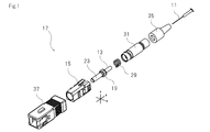
- FIG. 1 is an exploded perspective view of the optical connector of the present invention.
- FIG. 2 is a perspective view showing a mounting example of the optical connector of the present invention.
- FIG. 3A is a cross-sectional view taken along the line AA in FIG.
- FIG. 3B is an enlarged view of B in FIG.
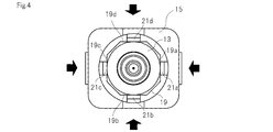
- FIG. 4 is a conceptual diagram when the plug frame of the present invention accommodates a ferrule.
- FIG. 5 is a conceptual diagram for explaining a multi-core fiber connection method using the optical connector of the present invention.
- FIG. 6 is a conceptual diagram when two multi-core fibers are connected using the optical connector of the present invention.
- FIG. 1 is an exploded perspective view of the optical connector of the present invention.
- FIG. 2 is a perspective view showing a mounting example of the optical connector of the present invention.
- FIG. 3A is a cross-sectional view taken along the line AA in FIG.
- FIG. 3B is an enlarged view of B in FIG.
- FIG. 4 is a conceptual diagram when the plug frame of the present invention accommodates a ferrule.
- the optical connector 17 of the present invention is fitted to the plug frame 15 via a ferrule 13 that holds and accommodates the optical fiber 11, a plug frame 15 that accommodates the ferrule 13, and a coil spring 29. It comprises a stop ring 31 to be mated, a connector boot 35, and a knob 37 for housing the above components.
- the optical connector 17 is an optical component used to connect a multi-core fiber and a single mode fiber or multi-core fibers.
- the core arrangement of the multi-cores is the same.
- the corresponding cores of the two multi-core fibers are optically connected by using the optical connector of the present invention.
- the multi-core fiber 11 is an optical fiber including a plurality of cores in one fiber as disclosed in the above-described patent document.
- An example of the multi-core fiber 11 is a fiber having a central core and one or more cores existing around the central core.
- the multi-core fiber 11 does not necessarily have a core at the center.
- the multi-core fiber used in the present invention may be a multi-core fiber having a core in which 2 to 4 (or more) cores are symmetrically arranged.
- the central core means a core existing at the center position of the multi-core fiber.
- the distance between the cores is, for example, 30 ⁇ m or more and 60 ⁇ m or less.
- the distance between cores means the distance from the center of a core to the center of an adjacent core.
- the ferrule 13 is a known optical fiber holding optical component.
- the ferrule 13 is a container for housing a part of the multi-core fiber 11 therein.
- the ferrule 13 is provided in the end part of the multi-core fiber 11, and is used in order to connect another optical fiber.
- the ferrule 13 may be one member or two or more members.
- a ferrule flange 19 is provided at the end portion of the ferrule body on a substantially cylindrical shape (column).
- the plug frame 15 is a container for accommodating the ferrule 13 therein.
- the plug frame 15 is not particularly limited as long as the leaf spring structures 21 a, 21 b, 21 c, and 21 d for applying pressure to the ferrule 13 are integrally formed therein and the ferrule 13 can be accommodated in the plug frame 15.
- An example of the plug frame 15 is a main body of the optical connector.
- the plug frame 15 is integrally formed by a mold using a resin such as nylon resin, polybutylene terephthalate (PBT) resin, or LCP resin (liquid crystal polymer).
- the ferrule 13 in the optical connector 17 of the present invention has at least one flat surface 19 on the outer peripheral surface.
- the flat surface may be approximately flat.
- the flat portion may be formed like the bottom portion of the groove.
- four grooves may be provided at positions rotated 90 degrees around the axis.
- the ferrule flange 19 is pressed by a leaf spring structure.
- the plug frame 15 has a leaf spring structure 21 for pressing the flat surface 19. As shown in FIG. 3, the leaf spring structure 21 is integrally formed in the plug frame 15.
- the flat surface 19 is provided on the outer peripheral surface of the ferrule 13, and it is pressurized from the plug frame 15 side using the leaf spring structure 21, thereby preventing rotational movement around the ferrule axis, The rotational movement of the fiber can be prevented.
- the optical connector 17 of the present invention contacts and pressurizes the flat surface of the outer periphery of the ferrule 13 by the leaf spring structure 21, the X, Y, and Z axis positions of the multicore fiber 11 can be moved. it can. For this reason, as described above, the X, Y, and Z axis positions can be moved while preventing the multi-core fiber from rotating about the axis.
- the optical connector 17 of the present invention is formed by integrally molding the leaf spring structure 21 in the plug frame 15, it is necessary to separately attach a component for pressing the flat surface 19 on the outer periphery of the ferrule 13 to the inside of the plug frame. Disappear.
- the optical connector 17 of the present invention it is not necessary to attach components including springs for pressurizing the flat surfaces 19 a, 19 b, 19 c, 19 d on the outer periphery of the ferrule 13 to the inside of the plug frame 15.
- a structure for pressurizing the flat surface on the outer periphery of the ferrule can be easily provided.
- the plug frame of the present invention When the plug frame of the present invention is manufactured, the plug frame and the leaf spring structure can be integrally manufactured by resin molding using a mold, for example. Therefore, an optical connector having a structure for pressurizing the flat surface on the outer periphery of the ferrule can be provided at a low cost.
- the preferred optical connector of the present invention is one in which four flat surfaces 19 a, 19 b, 19 c, 19 d exist on the outer peripheral surface of the ferrule 13.
- the plug frame 15 corresponds to the four flat surfaces 19a, 19b, 19c, 19d, and has four leaf spring structures 21a, 21b, 21c and 21d.
- a cross section of at least a portion pressed by the leaf spring in the ferrule 13 is on a square (the corner may be R). If the shape of the portion to be pressurized of the ferrule 13 is substantially square, it is possible to prevent the ferrule from rotating about the axis.
- the four flat surfaces be provided at positions rotated by 90 degrees around the central axis of the ferrule (or the central axis of the fiber).
- the member that presses the flat surface around the ferrule is a leaf spring.
- leaf spring structures 21a, 21b, 21c, and 21d exist on the opposing surfaces, respectively.
- the optical connector of the present invention can move the X and Y axis positions flexibly even when the outer end 23 of the ferrule is inserted into the split sleeve 25 in order to connect the fibers.
- the multi-core fiber can be prevented from rotating about the axis. For this reason, the fibers can be easily connected to each other, and the situation in which the connection loss due to the X and Y axis deviations is deteriorated can be prevented.
- the preferred optical connector of the present invention is one in which the outer end 23 of the ferrule 13 is inserted into an optical adapter having a split sleeve 25. Having such a configuration, another optical connector is inserted from the opposite end of the split sleeve 25 and brought into close contact, whereby the two optical fibers can be connected.
- the split sleeve 25 is an optical device for optically connecting the cores included in the two multi-core fibers and maintaining the connection state by accommodating the ferrules of the two optical connectors so as to be in close contact with each other. .
- the inside of the split sleeve 25 has a shape corresponding to the outer periphery of the outer end 23 of the ferrule 13, for example. For this reason, the split sleeve 25 can stably hold the two ferrules 13.
- FIG. 5 is a conceptual diagram for explaining a multi-core fiber connection method using the optical connector of the present invention.
- the outer end 23 of the ferrule 13 is inserted from one end of the split sleeve 25. That is, the inner diameter of the split sleeve 25 is sized to accommodate the outer end 23 of the ferrule 13.
- another optical connector is inserted from the opposite end of the split sleeve 25. This optical connector also contains a multi-core fiber.
- FIG. 6 is a conceptual diagram when two multi-core fibers are connected using the optical connector of the present invention. As shown in FIG. 6, an optical connector is inserted into each of the two ends of one split sleeve 25, and multi-core fibers accommodated in the respective optical connectors are brought into close contact with each other. In this way, each core included in the multi-core fiber is optically connected.
- the coil spring 29 is a member for urging the ferrule 13 forward by abutting against the ferrule 13 and pressurizing and sticking the fibers together.
- the stop ring 31 is a member that supports the rear end of the coil spring 29. In the example shown in FIG. 3, the stop ring 31 is fitted to the plug frame 15, and the coil spring 29 is in contact with the ferrule 13 in the plug frame 15.
- the connector boot 35 is for protecting the cable inserted into the optical fiber 11.
- the connector boot 35 is fitted to the stop ring 31 and protrudes outward from the knob 37.
- the connector boot 35 can reduce light transmission loss caused by a lateral pressure that increases when the optical fiber cable is bent.
- the knob 37 is a container for accommodating the above-described components therein. As shown in FIG. 2, the knob 37 is an assembly including the above-described components, whereby the optical connector 17 of the present invention is completed.
- the knob 37 has a rectangular shape, and is formed of a resin such as nylon resin, PBT resin, or LCP resin.
- a reference surface structure is provided on the ferrule flange. Then, pressure is applied by a leaf spring structure added to the surface structure portion in the plug frame.
- the ferrule is held by the connector without causing shaft rotation by pressurizing the flat surface on the outer periphery of the ferrule from four directions. With this structure, the ferrule is drawn to the back of the connector for close connection between the fibers, but the leaf spring structure slides in the Z-axis direction while maintaining the pressure applied to the flange of the ferrule, so that the axis of the ferrule does not rotate.
- the present invention can be used in the fields of optical equipment and optical information communication.
Landscapes
- Physics & Mathematics (AREA)
- General Physics & Mathematics (AREA)
- Optics & Photonics (AREA)
- Mechanical Coupling Of Light Guides (AREA)
- Optical Fibers, Optical Fiber Cores, And Optical Fiber Bundles (AREA)
Priority Applications (3)
| Application Number | Priority Date | Filing Date | Title |
|---|---|---|---|
| CN201480016874.4A CN105051584B (zh) | 2013-03-18 | 2014-03-05 | 多核光纤用光连接器 |
| EP14770723.6A EP2977803A4 (en) | 2013-03-18 | 2014-03-05 | OPTICAL COUPLER FOR MULTICOLORED FIBERS |
| US14/777,740 US9612407B2 (en) | 2013-03-18 | 2014-03-05 | Optical coupler for multicore fiber |
Applications Claiming Priority (2)
| Application Number | Priority Date | Filing Date | Title |
|---|---|---|---|
| JP2013-055821 | 2013-03-18 | ||
| JP2013055821A JP6138533B2 (ja) | 2013-03-18 | 2013-03-18 | マルチコアファイバ用光接続器 |
Publications (1)
| Publication Number | Publication Date |
|---|---|
| WO2014148253A1 true WO2014148253A1 (ja) | 2014-09-25 |
Family
ID=51579942
Family Applications (1)
| Application Number | Title | Priority Date | Filing Date |
|---|---|---|---|
| PCT/JP2014/055578 WO2014148253A1 (ja) | 2013-03-18 | 2014-03-05 | マルチコアファイバ用光接続器 |
Country Status (5)
| Country | Link |
|---|---|
| US (1) | US9612407B2 (zh) |
| EP (1) | EP2977803A4 (zh) |
| JP (1) | JP6138533B2 (zh) |
| CN (1) | CN105051584B (zh) |
| WO (1) | WO2014148253A1 (zh) |
Cited By (1)
| Publication number | Priority date | Publication date | Assignee | Title |
|---|---|---|---|---|
| EP3467559A1 (en) | 2017-10-04 | 2019-04-10 | Sumitomo Electric Industries, Ltd. | Optical connector and optical connection structure |
Families Citing this family (23)
| Publication number | Priority date | Publication date | Assignee | Title |
|---|---|---|---|---|
| CN105283787B (zh) | 2013-06-13 | 2018-05-25 | 美国北卡罗来纳康普公司 | 用于多芯光纤的连接器 |
| JP6354208B2 (ja) | 2014-02-28 | 2018-07-11 | 住友電気工業株式会社 | 光結合部材 |
| MX2018010817A (es) | 2016-03-10 | 2019-01-10 | Corning Optical Communications LLC | Conectores de fibra óptica a basé de férula con balanceo de retracción de la férula. |
| EP3879321A1 (en) | 2017-06-28 | 2021-09-15 | Corning Research & Development Corporation | Fiber optic connectors having a keying structure |
| US11187859B2 (en) | 2017-06-28 | 2021-11-30 | Corning Research & Development Corporation | Fiber optic connectors and methods of making the same |
| US10359577B2 (en) | 2017-06-28 | 2019-07-23 | Corning Research & Development Corporation | Multiports and optical connectors with rotationally discrete locking and keying features |
| US11300746B2 (en) | 2017-06-28 | 2022-04-12 | Corning Research & Development Corporation | Fiber optic port module inserts, assemblies and methods of making the same |
| US11668890B2 (en) | 2017-06-28 | 2023-06-06 | Corning Research & Development Corporation | Multiports and other devices having optical connection ports with securing features and methods of making the same |
| JPWO2019044079A1 (ja) * | 2017-08-30 | 2020-08-13 | 住友電気工業株式会社 | コネクタプラグ、光コネクタ及び光接続構造 |
| US10641967B1 (en) | 2018-11-16 | 2020-05-05 | Corning Research & Development Corporation | Multiport assemblies including a modular adapter support array |
| US10768382B2 (en) | 2018-11-29 | 2020-09-08 | Corning Research & Development Corporation | Multiport assemblies including access apertures and a release tool |
| US11294133B2 (en) | 2019-07-31 | 2022-04-05 | Corning Research & Development Corporation | Fiber optic networks using multiports and cable assemblies with cable-to-connector orientation |
| US11487073B2 (en) | 2019-09-30 | 2022-11-01 | Corning Research & Development Corporation | Cable input devices having an integrated locking feature and assemblies using the cable input devices |
| EP3805827A1 (en) | 2019-10-07 | 2021-04-14 | Corning Research & Development Corporation | Fiber optic terminals and fiber optic networks having variable ratio couplers |
| US11650388B2 (en) | 2019-11-14 | 2023-05-16 | Corning Research & Development Corporation | Fiber optic networks having a self-supporting optical terminal and methods of installing the optical terminal |
| US11536921B2 (en) | 2020-02-11 | 2022-12-27 | Corning Research & Development Corporation | Fiber optic terminals having one or more loopback assemblies |
| JP7261778B2 (ja) * | 2020-09-29 | 2023-04-20 | Kddi株式会社 | マルチコア光ファイバの接続器 |
| US11604320B2 (en) | 2020-09-30 | 2023-03-14 | Corning Research & Development Corporation | Connector assemblies for telecommunication enclosures |
| US11686913B2 (en) | 2020-11-30 | 2023-06-27 | Corning Research & Development Corporation | Fiber optic cable assemblies and connector assemblies having a crimp ring and crimp body and methods of fabricating the same |
| US11880076B2 (en) | 2020-11-30 | 2024-01-23 | Corning Research & Development Corporation | Fiber optic adapter assemblies including a conversion housing and a release housing |
| US11927810B2 (en) | 2020-11-30 | 2024-03-12 | Corning Research & Development Corporation | Fiber optic adapter assemblies including a conversion housing and a release member |
| US11947167B2 (en) | 2021-05-26 | 2024-04-02 | Corning Research & Development Corporation | Fiber optic terminals and tools and methods for adjusting a split ratio of a fiber optic terminal |
| WO2023067677A1 (ja) * | 2021-10-19 | 2023-04-27 | 日本電信電話株式会社 | 光接続装置及びこれを用いた光スイッチ |
Citations (10)
| Publication number | Priority date | Publication date | Assignee | Title |
|---|---|---|---|---|
| JPH10509523A (ja) * | 1994-06-22 | 1998-09-14 | ザ ウィタカー コーポレーション | 組立性向上手段を有する光ファイバコネクタ |
| JPH1138272A (ja) * | 1997-07-22 | 1999-02-12 | Mitsubishi Electric Corp | 光ファイバ用コネクタおよびコネクタ係止構造 |
| JP2003185881A (ja) * | 2001-10-12 | 2003-07-03 | Seiko Instruments Inc | フェルール |
| JP2009115864A (ja) * | 2007-11-01 | 2009-05-28 | Japan Aviation Electronics Industry Ltd | 光コネクタ組立治具 |
| WO2010038861A1 (ja) | 2008-10-03 | 2010-04-08 | 国立大学法人 横浜国立大学 | 結合系マルチコアファイバ、結合モード合分波器、マルチコアファイバ伝送システム、およびマルチコアファイバ伝送方法 |
| JP2010286548A (ja) | 2009-06-09 | 2010-12-24 | Sumitomo Electric Ind Ltd | マルチコアファイバ及びそれを含む光コネクタ |
| JP2010286718A (ja) | 2009-06-12 | 2010-12-24 | Sumitomo Electric Ind Ltd | マルチコアファイバ端末及びその接続構造 |
| JP2011075829A (ja) * | 2009-09-30 | 2011-04-14 | Fujikura Ltd | コネクタ付き光伝送体、光コネクタ |
| JP2011158768A (ja) | 2010-02-02 | 2011-08-18 | Sumitomo Electric Ind Ltd | マルチコア光ファイバ及びマルチコア光ファイバの接続方法 |
| WO2011116133A1 (en) * | 2010-03-16 | 2011-09-22 | OFS Fitel LLC, a Delaware Limited Liability Company | Simplex connectors for multicore optical fiber cables |
Family Cites Families (14)
| Publication number | Priority date | Publication date | Assignee | Title |
|---|---|---|---|---|
| US4279467A (en) * | 1979-11-05 | 1981-07-21 | International Telephone And Telegraph Corporation | Fiber optic connector |
| US4807957A (en) * | 1987-10-15 | 1989-02-28 | Siecor Corporation | Connector for optical fibers |
| US5253315A (en) * | 1990-12-24 | 1993-10-12 | Fentress Vernon A | Method and apparatus for installing a fiber optic cable by capture of a coupling nut or coupling nut assembly |
| US5214730A (en) * | 1991-05-13 | 1993-05-25 | Nippon Telegraph And Telephone Corporation | Multifiber optical connector plug with low reflection and low insertion loss |
| KR100713430B1 (ko) * | 1999-06-01 | 2007-05-04 | 니폰덴신뎅와 가부시키가이샤 | 광커넥터 플러그, 그 제조방법 및 조립공구 |
| US6287018B1 (en) * | 1999-07-28 | 2001-09-11 | Lucent Technologies Inc. | Tunable optical fiber connector |
| JP3641201B2 (ja) * | 2000-10-31 | 2005-04-20 | 三和電気工業株式会社 | 光コネクタプラグ |
| JP4266319B2 (ja) * | 2002-09-06 | 2009-05-20 | 株式会社精工技研 | 光コネクタプラグ及び光コネクタ |
| JP4064784B2 (ja) * | 2002-10-16 | 2008-03-19 | 矢崎総業株式会社 | 光コネクタ |
| US7178988B2 (en) * | 2003-07-15 | 2007-02-20 | Seikoh Giken Co., Ltd. | Optical connector plug and method for assembling same |
| JP4328712B2 (ja) * | 2004-03-10 | 2009-09-09 | 株式会社精工技研 | 光コネクタプラグ及び光コネクタ |
| US20070133926A1 (en) * | 2005-12-13 | 2007-06-14 | Semmler Scott E | Flexible cam member for fiber optic mechanical splice connector |
| CN201740883U (zh) * | 2010-05-17 | 2011-02-09 | 深圳日海通讯技术股份有限公司 | 一种fc型光纤插头 |
| CN105283787B (zh) * | 2013-06-13 | 2018-05-25 | 美国北卡罗来纳康普公司 | 用于多芯光纤的连接器 |
-
2013
- 2013-03-18 JP JP2013055821A patent/JP6138533B2/ja active Active
-
2014
- 2014-03-05 US US14/777,740 patent/US9612407B2/en active Active
- 2014-03-05 CN CN201480016874.4A patent/CN105051584B/zh active Active
- 2014-03-05 EP EP14770723.6A patent/EP2977803A4/en not_active Withdrawn
- 2014-03-05 WO PCT/JP2014/055578 patent/WO2014148253A1/ja active Application Filing
Patent Citations (11)
| Publication number | Priority date | Publication date | Assignee | Title |
|---|---|---|---|---|
| JPH10509523A (ja) * | 1994-06-22 | 1998-09-14 | ザ ウィタカー コーポレーション | 組立性向上手段を有する光ファイバコネクタ |
| JPH1138272A (ja) * | 1997-07-22 | 1999-02-12 | Mitsubishi Electric Corp | 光ファイバ用コネクタおよびコネクタ係止構造 |
| JP2003185881A (ja) * | 2001-10-12 | 2003-07-03 | Seiko Instruments Inc | フェルール |
| JP2009115864A (ja) * | 2007-11-01 | 2009-05-28 | Japan Aviation Electronics Industry Ltd | 光コネクタ組立治具 |
| WO2010038861A1 (ja) | 2008-10-03 | 2010-04-08 | 国立大学法人 横浜国立大学 | 結合系マルチコアファイバ、結合モード合分波器、マルチコアファイバ伝送システム、およびマルチコアファイバ伝送方法 |
| WO2010038863A1 (ja) | 2008-10-03 | 2010-04-08 | 国立大学法人 横浜国立大学 | 非結合系マルチコアファイバ |
| JP2010286548A (ja) | 2009-06-09 | 2010-12-24 | Sumitomo Electric Ind Ltd | マルチコアファイバ及びそれを含む光コネクタ |
| JP2010286718A (ja) | 2009-06-12 | 2010-12-24 | Sumitomo Electric Ind Ltd | マルチコアファイバ端末及びその接続構造 |
| JP2011075829A (ja) * | 2009-09-30 | 2011-04-14 | Fujikura Ltd | コネクタ付き光伝送体、光コネクタ |
| JP2011158768A (ja) | 2010-02-02 | 2011-08-18 | Sumitomo Electric Ind Ltd | マルチコア光ファイバ及びマルチコア光ファイバの接続方法 |
| WO2011116133A1 (en) * | 2010-03-16 | 2011-09-22 | OFS Fitel LLC, a Delaware Limited Liability Company | Simplex connectors for multicore optical fiber cables |
Non-Patent Citations (1)
| Title |
|---|
| See also references of EP2977803A4 * |
Cited By (3)
| Publication number | Priority date | Publication date | Assignee | Title |
|---|---|---|---|---|
| EP3467559A1 (en) | 2017-10-04 | 2019-04-10 | Sumitomo Electric Industries, Ltd. | Optical connector and optical connection structure |
| JP2019066772A (ja) * | 2017-10-04 | 2019-04-25 | 住友電気工業株式会社 | 光コネクタおよび光接続構造 |
| JP7047314B2 (ja) | 2017-10-04 | 2022-04-05 | 住友電気工業株式会社 | 光コネクタおよび光接続構造 |
Also Published As
| Publication number | Publication date |
|---|---|
| US20160259133A1 (en) | 2016-09-08 |
| CN105051584B (zh) | 2017-11-10 |
| EP2977803A4 (en) | 2016-10-19 |
| JP2014182229A (ja) | 2014-09-29 |
| CN105051584A (zh) | 2015-11-11 |
| JP6138533B2 (ja) | 2017-05-31 |
| US9612407B2 (en) | 2017-04-04 |
| EP2977803A1 (en) | 2016-01-27 |
Similar Documents
| Publication | Publication Date | Title |
|---|---|---|
| JP6138533B2 (ja) | マルチコアファイバ用光接続器 | |
| JP6063225B2 (ja) | 回転防止機構を有するマルチコアファイバ用接続器 | |
| US10429592B2 (en) | Receptacle connector and optical coupling structure | |
| JP6390370B2 (ja) | アダプタと光コネクタ結合システム | |
| JP6354208B2 (ja) | 光結合部材 | |
| US10670814B2 (en) | Optical connector and optical connection structure | |
| JP7047314B2 (ja) | 光コネクタおよび光接続構造 | |
| US20200166715A1 (en) | Connector plug, optical connector, and optical connection structure | |
| JP2018081144A (ja) | 光コネクタ | |
| JP2015172639A5 (zh) | ||
| JP2019101233A (ja) | 光ファイバ付きフェルール及び光ファイバ付きフェルールの製造方法 | |
| JP6447038B2 (ja) | 光コネクタ結合システム | |
| US20130315542A1 (en) | Connector assembly for optical fiber | |
| JP2014219591A (ja) | 光コネクタプラグのガタ止め機構 | |
| JP2021119363A (ja) | 光コネクタおよび光接続構造 | |
| JP6013800B2 (ja) | 光ループバックコネクタ | |
| JP2011175286A (ja) | 光コネクタ | |
| JP7207293B2 (ja) | 光コネクタ | |
| JP7472987B2 (ja) | 光コネクタおよび光接続構造 | |
| JP2014092748A (ja) | 光接続構造、光アダプタおよび光コネクタプラグ | |
| JP2004279936A (ja) | 光コネクタの製造方法、光コネクタ及び光コネクタ組立体 |
Legal Events
| Date | Code | Title | Description |
|---|---|---|---|
| WWE | Wipo information: entry into national phase |
Ref document number: 201480016874.4 Country of ref document: CN |
|
| 121 | Ep: the epo has been informed by wipo that ep was designated in this application |
Ref document number: 14770723 Country of ref document: EP Kind code of ref document: A1 |
|
| WWE | Wipo information: entry into national phase |
Ref document number: 2014770723 Country of ref document: EP |
|
| WWE | Wipo information: entry into national phase |
Ref document number: 14777740 Country of ref document: US |
|
| NENP | Non-entry into the national phase |
Ref country code: DE |