WO2014129442A1 - 放射線画像処理装置および方法、並びに放射線撮影装置 - Google Patents
放射線画像処理装置および方法、並びに放射線撮影装置 Download PDFInfo
- Publication number
- WO2014129442A1 WO2014129442A1 PCT/JP2014/053721 JP2014053721W WO2014129442A1 WO 2014129442 A1 WO2014129442 A1 WO 2014129442A1 JP 2014053721 W JP2014053721 W JP 2014053721W WO 2014129442 A1 WO2014129442 A1 WO 2014129442A1
- Authority
- WO
- WIPO (PCT)
- Prior art keywords
- image
- ray
- images
- radiographic
- subject
- Prior art date
- Legal status (The legal status is an assumption and is not a legal conclusion. Google has not performed a legal analysis and makes no representation as to the accuracy of the status listed.)
- Ceased
Links
Images









Classifications
-
- A—HUMAN NECESSITIES
- A61—MEDICAL OR VETERINARY SCIENCE; HYGIENE
- A61B—DIAGNOSIS; SURGERY; IDENTIFICATION
- A61B6/00—Apparatus or devices for radiation diagnosis; Apparatus or devices for radiation diagnosis combined with radiation therapy equipment
- A61B6/42—Arrangements for detecting radiation specially adapted for radiation diagnosis
- A61B6/4208—Arrangements for detecting radiation specially adapted for radiation diagnosis characterised by using a particular type of detector
- A61B6/4233—Arrangements for detecting radiation specially adapted for radiation diagnosis characterised by using a particular type of detector using matrix detectors
-
- G—PHYSICS
- G06—COMPUTING OR CALCULATING; COUNTING
- G06T—IMAGE DATA PROCESSING OR GENERATION, IN GENERAL
- G06T7/00—Image analysis
- G06T7/30—Determination of transform parameters for the alignment of images, i.e. image registration
-
- A—HUMAN NECESSITIES
- A61—MEDICAL OR VETERINARY SCIENCE; HYGIENE
- A61B—DIAGNOSIS; SURGERY; IDENTIFICATION
- A61B6/00—Apparatus or devices for radiation diagnosis; Apparatus or devices for radiation diagnosis combined with radiation therapy equipment
- A61B6/46—Arrangements for interfacing with the operator or the patient
- A61B6/461—Displaying means of special interest
- A61B6/463—Displaying means of special interest characterised by displaying multiple images or images and diagnostic data on one display
-
- A—HUMAN NECESSITIES
- A61—MEDICAL OR VETERINARY SCIENCE; HYGIENE
- A61B—DIAGNOSIS; SURGERY; IDENTIFICATION
- A61B6/00—Apparatus or devices for radiation diagnosis; Apparatus or devices for radiation diagnosis combined with radiation therapy equipment
- A61B6/48—Diagnostic techniques
- A61B6/486—Diagnostic techniques involving generating temporal series of image data
-
- A—HUMAN NECESSITIES
- A61—MEDICAL OR VETERINARY SCIENCE; HYGIENE
- A61B—DIAGNOSIS; SURGERY; IDENTIFICATION
- A61B6/00—Apparatus or devices for radiation diagnosis; Apparatus or devices for radiation diagnosis combined with radiation therapy equipment
- A61B6/52—Devices using data or image processing specially adapted for radiation diagnosis
- A61B6/5205—Devices using data or image processing specially adapted for radiation diagnosis involving processing of raw data to produce diagnostic data
-
- A—HUMAN NECESSITIES
- A61—MEDICAL OR VETERINARY SCIENCE; HYGIENE
- A61B—DIAGNOSIS; SURGERY; IDENTIFICATION
- A61B6/00—Apparatus or devices for radiation diagnosis; Apparatus or devices for radiation diagnosis combined with radiation therapy equipment
- A61B6/54—Control of apparatus or devices for radiation diagnosis
- A61B6/542—Control of apparatus or devices for radiation diagnosis involving control of exposure
-
- A—HUMAN NECESSITIES
- A61—MEDICAL OR VETERINARY SCIENCE; HYGIENE
- A61B—DIAGNOSIS; SURGERY; IDENTIFICATION
- A61B6/00—Apparatus or devices for radiation diagnosis; Apparatus or devices for radiation diagnosis combined with radiation therapy equipment
- A61B6/54—Control of apparatus or devices for radiation diagnosis
- A61B6/545—Control of apparatus or devices for radiation diagnosis involving automatic set-up of acquisition parameters
-
- A—HUMAN NECESSITIES
- A61—MEDICAL OR VETERINARY SCIENCE; HYGIENE
- A61B—DIAGNOSIS; SURGERY; IDENTIFICATION
- A61B6/00—Apparatus or devices for radiation diagnosis; Apparatus or devices for radiation diagnosis combined with radiation therapy equipment
- A61B6/58—Testing, adjusting or calibrating thereof
- A61B6/589—Setting distance between source unit and patient
-
- G—PHYSICS
- G06—COMPUTING OR CALCULATING; COUNTING
- G06T—IMAGE DATA PROCESSING OR GENERATION, IN GENERAL
- G06T7/00—Image analysis
- G06T7/30—Determination of transform parameters for the alignment of images, i.e. image registration
- G06T7/33—Determination of transform parameters for the alignment of images, i.e. image registration using feature-based methods
-
- G—PHYSICS
- G06—COMPUTING OR CALCULATING; COUNTING
- G06T—IMAGE DATA PROCESSING OR GENERATION, IN GENERAL
- G06T2200/00—Indexing scheme for image data processing or generation, in general
- G06T2200/24—Indexing scheme for image data processing or generation, in general involving graphical user interfaces [GUIs]
-
- G—PHYSICS
- G06—COMPUTING OR CALCULATING; COUNTING
- G06T—IMAGE DATA PROCESSING OR GENERATION, IN GENERAL
- G06T2207/00—Indexing scheme for image analysis or image enhancement
- G06T2207/10—Image acquisition modality
- G06T2207/10016—Video; Image sequence
-
- G—PHYSICS
- G06—COMPUTING OR CALCULATING; COUNTING
- G06T—IMAGE DATA PROCESSING OR GENERATION, IN GENERAL
- G06T2207/00—Indexing scheme for image analysis or image enhancement
- G06T2207/10—Image acquisition modality
- G06T2207/10116—X-ray image
-
- G—PHYSICS
- G06—COMPUTING OR CALCULATING; COUNTING
- G06T—IMAGE DATA PROCESSING OR GENERATION, IN GENERAL
- G06T2207/00—Indexing scheme for image analysis or image enhancement
- G06T2207/10—Image acquisition modality
- G06T2207/10141—Special mode during image acquisition
- G06T2207/10144—Varying exposure
-
- G—PHYSICS
- G06—COMPUTING OR CALCULATING; COUNTING
- G06T—IMAGE DATA PROCESSING OR GENERATION, IN GENERAL
- G06T2207/00—Indexing scheme for image analysis or image enhancement
- G06T2207/20—Special algorithmic details
- G06T2207/20212—Image combination
- G06T2207/20221—Image fusion; Image merging
-
- G—PHYSICS
- G06—COMPUTING OR CALCULATING; COUNTING
- G06T—IMAGE DATA PROCESSING OR GENERATION, IN GENERAL
- G06T2207/00—Indexing scheme for image analysis or image enhancement
- G06T2207/30—Subject of image; Context of image processing
- G06T2207/30004—Biomedical image processing
- G06T2207/30061—Lung
Definitions
- the present invention relates to a radiation image processing apparatus and method, and a radiation imaging apparatus.
- the X-ray imaging system includes an X-ray generation apparatus that generates X-rays and an X-ray imaging apparatus that captures an X-ray image formed by X-rays transmitted through a subject (patient).
- the X-ray generation apparatus inputs an X-ray source that irradiates an X-ray toward a subject, a radiation source control apparatus that controls driving of the X-ray source, and an instruction for operating the X-ray source to the radiation source control apparatus. It has an irradiation switch.
- the X-ray imaging apparatus includes: an X-ray image detection apparatus that detects an X-ray image corresponding to X-rays transmitted through a subject; drive control of the X-ray image detection apparatus; image processing on the X-ray image; It has a console for displaying.
- the X-ray image detection apparatus includes a sensor panel called a flat panel detector (FPD) and detects an X-ray image electronically.
- This sensor panel has an imaging region in which a plurality of pixels that accumulate signal charges according to the amount of incident X-rays are arranged.
- the pixel includes a photoelectric conversion unit that generates and accumulates charges, and a switching element such as a TFT.
- the sensor panel reads out the signal charge accumulated in the photoelectric conversion unit of each pixel to the signal processing circuit through the signal line provided for each pixel column in response to the ON operation of the switching element, and the signal processing circuit reads the signal charge in the signal processing circuit.
- An X-ray image is electrically detected by converting it into a voltage signal.
- an X-ray dose is detected during X-ray irradiation, and the accumulated dose is an integrated value of the dose.
- AEC Automatic Exposure Control
- the cumulative dose of X-rays irradiated by the X-ray source is the tube current time product (mAs value), which is the product of the X-ray irradiation time and the tube current that defines the X-ray dose irradiated by the X-ray source per unit time. ).
- the X-ray transmittance changes depending on individual differences such as the physique of the subject. AEC is performed to obtain a more appropriate image quality.
- a dose detection device that detects the dose of X-rays transmitted through the subject is used.
- a dose detection apparatus an ion chamber that can be used in combination with an X-ray image detection apparatus is known.
- the ion chamber has, for example, dose detection sensors disposed at a total of three positions, two upper positions symmetrical to the left and right lung fields at the time of chest imaging and the lower position, and the front surface of the X-ray image detection apparatus. Or it is attached to cover the back.
- two dose detection sensors at the upper position are selected as the daylighting fields that serve as a reference for dose detection in AEC.
- positioning is performed to match the relative positional relationship between the subject and the X-ray image detection apparatus so that the selected daylighting field and the left and right lung fields of the subject face each other. If positioning is not performed correctly, positioning of the lung field and the light field is shifted carefully, and proper AEC cannot be performed. After such positioning is completed, shooting is started. During imaging, the timing for stopping the X-ray irradiation is determined based on the dose signal output from the dose detection sensor selected as the daylighting field.
- the sensor panels described in Japanese Patent Application Laid-Open Nos. 07-201490 and 2002-000590 operate pixels in an imaging region for detecting an X-ray image as a dose detection sensor. Arbitrary pixels can be selected as a daylighting field.
- the light is collected as a preparatory work before photographing. After field selection and subject positioning according to the selected daylighting field, shooting is started.
- the inventors further promoted a technique for operating the pixel of the sensor panel described in JP-A-07-201490 and JP-A-2002-000590 as a dose detection sensor, and automatically set the daylighting field during photographing.
- some of the pixels of the sensor panel are detection pixels that function as a dose detection sensor, and these are distributed and arranged in the imaging region.
- a lighting field is set based on the dose signal output from a detection pixel during imaging
- AEC is performed based on the dose signal from the detection pixel set as the daylighting field. According to this technique, it is not necessary to select a daylighting field that has been necessary as a preparatory work for conventional photographing. In addition, since the daylighting field is automatically set according to the relative positional relationship between the subject and the X-ray image detection apparatus, it is not necessary to position the subject as carefully as in the past.
- follow-up observation is performed by comparatively reading a plurality of X-ray images obtained by imaging the same imaging region of the same subject several times at intervals, such as before and after surgery. Done.
- a plurality of X-ray images are displayed on a display screen of a display so that they can be comparatively interpreted by displaying them in parallel or switching one image at a time.
- an X-ray image before surgery has a subject located substantially in the center, whereas an X-ray image after surgery has the subject moved to the right or left. If the subject position is not constant, comparative interpretation is difficult. For this reason, it is preferable that the position of the subject in the X-ray image is constant between the plurality of X-ray images used for the follow-up observation.
- image analysis such as pattern recognition is performed on a plurality of X-ray images to recognize the position of the subject in each X-ray image, and each X-ray is based on the recognized position of the subject. It is conceivable to perform alignment processing for matching the positions of the subjects in the image.
- the method of recognizing the position of the subject in the X-ray image by image analysis is complicated and takes time. Therefore, a simpler solution to the above problem has been demanded.
- the present invention provides a radiographic image processing apparatus and method, and a radiographic apparatus capable of obtaining a display image suitable for follow-up observation by a simple method even when a technique for automatically setting a daylighting field during imaging is used.
- the purpose is to provide.
- a radiological image processing apparatus of the present invention has an imaging region in which a plurality of pixels are arranged, uses a radiological image detection apparatus that detects a radiographic image of a subject, and uses the same subject of the same subject.
- a radiographic image processing apparatus that performs image processing on a plurality of radiographic images obtained by imaging a radiographic region multiple times at intervals, an image acquisition unit, a lighting field information acquisition unit, and an alignment processing unit Is provided.
- the image acquisition unit acquires a plurality of radiation images.
- the daylighting field information acquisition unit is automatically set in the imaging region according to the position of the subject to be positioned at the time of AEC executed by the radiological image detection apparatus at the time of imaging, and is recorded in association with each of a plurality of radiographic images.
- the daylight field information indicating the position of the daylight field is acquired.
- the alignment processing unit based on the lighting field information acquired by the lighting field information acquisition unit, for the plurality of display images corresponding to the plurality of radiation images, the position of the subject depicted in each of the plurality of radiation images Alignment processing for matching the two is executed.
- the alignment processing unit matches the positions of the subjects in the plurality of display images by aligning the positions of the lighting fields of the plurality of radiation images.
- the daylight field information is preferably coordinate information representing the position of the daylight field in the radiation image.
- the alignment processing unit obtains a reference point for alignment from within the lighting field and executes the alignment process.
- the reference point is, for example, the center of a circumscribed rectangular frame that circumscribes the outer shape of the lighting field and surrounds the entire lighting field.
- the alignment processing unit executes the alignment process using one of the plurality of radiographic images as a reference image and using the position of the daylighting field of the reference image as a reference.
- the reference image is one radiation image selected from a plurality of radiation images by manual setting or automatic setting.
- the alignment processing unit executes the alignment process by displacing the drawing position of the display image with respect to the display frame for drawing the display image. It is preferable to include a masking processing unit that performs a masking process on a blank portion generated by the displacement of the drawing position.
- the radiographic image processing method of the present invention uses a radiographic image detection device that has an imaging region in which a plurality of pixels are arranged and detects a radiographic image of a subject, and uses the same imaging region of the same subject to separate the time.
- a radiographic image processing method that performs image processing on a plurality of radiographic images obtained by imaging a plurality of times, and includes an image acquisition step, a lighting field information acquisition step, and an alignment processing step.
- the lighting field information acquisition step is automatically set in the imaging region according to the position of the subject to be positioned during AEC executed by the radiological image detection apparatus at the time of imaging, and is recorded in association with each of a plurality of radiographic images.
- the daylight field information representing the position of the daylight field is acquired by the daylight field information acquisition unit.
- the alignment processing step based on the lighting field information acquired in the lighting field information acquisition step, the position of the subject depicted in each of the plurality of radiation images for the plurality of display images corresponding to the plurality of radiation images
- the alignment processing unit executes alignment processing for matching the two.
- the radiation imaging apparatus of the present invention has an imaging region in which a plurality of pixels are arranged, uses a radiation image detection apparatus that detects a radiation image of a subject, and the radiation image detection apparatus, and uses the same imaging region of the same subject. And a radiological image processing apparatus that performs image processing on a plurality of radiographic images obtained by imaging a plurality of times at intervals.
- the radiation image processing apparatus includes an image acquisition unit, a lighting field information acquisition unit, and a position alignment processing unit.
- the image acquisition unit acquires a plurality of radiation images.
- the daylighting field information acquisition unit is automatically set in the imaging region according to the position of the subject to be positioned at the time of AEC executed by the radiological image detection apparatus at the time of imaging, and is recorded in association with each of a plurality of radiographic images.
- the daylight field information indicating the position of the daylight field is acquired.
- the alignment processing unit based on the lighting field information acquired by the lighting field information acquisition unit, for the plurality of display images corresponding to the plurality of radiation images, the position of the subject depicted in each of the plurality of radiation images Alignment processing for matching the two is executed.
- the radiological image detection apparatus preferably has a panel unit, a plurality of dose detection sensors, a lighting field setting unit, and an AEC unit.
- An imaging region is formed in the panel unit.
- the plurality of dose detection sensors are arranged in a distributed manner in the imaging region, detect the radiation dose reaching the imaging region, and output a dose signal corresponding thereto.
- the daylighting field setting unit automatically sets the daylighting field based on dose signals output from a plurality of dose detection sensors during imaging.
- the AEC unit performs AEC based on the dose signal output from the dose detection sensor in the lighting field set by the lighting field setting unit.
- display corresponding to a plurality of radiographic images obtained by imaging the same imaging region of the same subject a plurality of times at intervals based on the daylighting field information automatically set during imaging Since the image alignment processing is performed, a display image suitable for follow-up observation can be obtained by a simple method even when a technique for automatically setting a daylighting field during photographing is used.
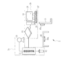
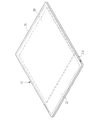
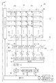
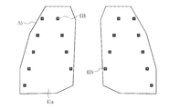
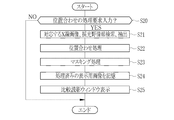
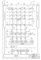
- FIG. 1 is a schematic diagram of an X-ray imaging system. It is a figure which shows an imaging condition table. It is a block diagram which shows the internal structure of a radiation source control apparatus. It is an external appearance perspective view which shows an electronic cassette. It is a block diagram which shows the internal structure of an electronic cassette. It is explanatory drawing for demonstrating arrangement
- an X-ray imaging system 2 instructs an X-ray source 10, a radiation source control device 11 that controls the operation of the X-ray source 10, and a warm-up start and an X-ray irradiation start to the X-ray source 10.
- an AEC function for stopping X-ray irradiation when the accumulated dose of X-rays reaches a target dose, and detecting X-rays transmitted through the subject (patient) to display an X-ray image
- the X-ray source 10, the radiation source control device 11, and the irradiation switch 12 constitute an X-ray generator 2a
- the electronic cassette 13, and the console 14 constitute an X-ray imaging device 2b, respectively.
- a radiation source moving device (not shown) for setting the X-ray source 10 in a desired direction and position is provided.
- the X-ray source 10 includes a standing imaging table 15 and a supine imaging table 16. Shared by.
- the X-ray source 10 includes an X-ray tube and an irradiation field limiter (collimator) that limits an X-ray irradiation field emitted from the X-ray tube.
- the X-ray tube has a cathode that is a filament that emits thermoelectrons, and an anode (target) that emits X-rays when the thermoelectrons emitted from the cathode collide.
- the anode starts rotating, and the warm-up ends when the specified rotational speed is reached.
- the irradiation field limiter has, for example, four lead plates that shield X-rays arranged on each side of a square, and a rectangular irradiation opening that transmits X-rays is formed in the center.
- the size of the irradiation aperture is changed by moving the position, and the angle range of the emitted X-ray is adjusted in two directions, vertical and horizontal. This limits the X-ray irradiation field.
- the console 14 is communicably connected to the electronic cassette 13 by a wired method or a wireless method, and controls the operation of the electronic cassette 13 according to an input operation from an operator such as a radiologist via an input device 17 such as a keyboard. To do.
- the X-ray image from the electronic cassette 13 is displayed on the display 18 of the console 14, and the data is stored in a storage device 19 such as a hard disk or memory in the console 14 or an image storage server connected to the console 14 over a network.
- a storage device 19 such as a hard disk or memory in the console 14 or an image storage server connected to the console 14 over a network.
- the console 14 receives an input of an examination order including information such as a subject's name, sex, age, imaging region, and imaging purpose, and displays the examination order on the display 18.
- the examination order is input from an external system that manages patient information such as HIS (Hospital Information System) and RIS (Radiation Information System) and examination information related to radiation examination, or is manually input by an operator.
- the examination order includes items of imaging regions such as the head, chest, abdomen, hands, and fingers.
- the imaging region includes imaging directions such as front, side, oblique, PA (X-rays are irradiated from the back of the subject), and AP (X-rays are irradiated from the front of the subject).
- the operator confirms the contents of the inspection order on the display 18 and inputs the photographing conditions corresponding to the contents with the input device 17 through the operation screen displayed on the display 18.
- the storage device 19 stores a shooting condition table 20 in which a plurality of shooting conditions are recorded in advance.
- the imaging conditions include an imaging region, a tube voltage (unit: kV) that determines the energy spectrum of X-rays irradiated by the X-ray source 10, a tube current (unit: mA) that determines an irradiation amount per unit time, and X-ray irradiation. Time (unit: s) and irradiation stop threshold are included.
- the tube current time product (mAs), which is the product of both, is used. Value) may be input.
- mAs tube current time product
- the irradiation stop threshold is information for the AEC unit 57 (see FIG. 5) to determine the stop of X-ray irradiation.
- FIG. 2 only the chest AP and the chest PA are illustrated as imaging parts, but actually imaging conditions corresponding to other imaging parts such as the head, abdomen, and legs, and irradiation stop thresholds corresponding thereto are also provided. It is remembered.
- X-rays are displayed on the console 14 from the position of the X-ray angle range in two vertical and horizontal directions set in the irradiation field limiter of the X-ray source 10 and the imaging region 40 (see FIG. 5) of the electronic cassette 13 together with the imaging conditions.
- Information on SID Source Image Distance
- SID Source Image Distance
- the radiation source control device 11 boosts the input voltage with a transformer to generate a high-voltage tube voltage, supplies the X-ray source 10 through a high-voltage cable, and the X-ray source 10.
- a control unit 22 that controls a tube voltage and a tube current to be applied, an X-ray irradiation time, a memory 23, a touch panel 24, and an irradiation signal I / F 25 that mediates transmission / reception of signals with the electronic cassette 13 are provided.
- the irradiation switch 12, the memory 23, and the touch panel 24 are connected to the control unit 22.
- the irradiation switch 12 is a switch for inputting an instruction to the control unit 22 and can be pressed in two stages. When the irradiation switch 12 is pushed one step (half-pressed), the control unit 22 issues a warm-up start signal to the high voltage generator 21 to cause the X-ray source 10 to start warm-up.
- the control unit 22 When the irradiation switch 12 is pressed one step (half-pressed), the control unit 22 performs synchronization control by transmitting / receiving a synchronization signal to / from the electronic cassette 13. Further, when the irradiation switch 12 is pressed in two steps (fully pressed), the control unit 22 issues an irradiation start signal to the high voltage generator 21 to start X-ray irradiation by the X-ray source 10.
- the memory 23 stores several types of imaging conditions such as tube voltage, tube current, and irradiation time in advance.
- the shooting conditions are manually set by the operator through the touch panel 24.
- a plurality of types of shooting conditions read from the memory 23 are displayed on the touch panel 24.
- An imaging condition is set for the radiation source control device 11 when the operator selects an imaging condition that is the same as the imaging condition input to the console 14 from the displayed imaging conditions.
- the value of the shooting condition can be finely adjusted.
- the controller 22 has a built-in timer 26 for stopping the X-ray irradiation when the set irradiation time is reached. Note that the radiation source control device 11 and the console 14 may be connected, and the imaging conditions set in the radiation source control device 11 may be automated by transmitting the imaging conditions input to the console 14 to the radiation source control device 11. .
- the irradiation time when using the AEC function of the electronic cassette 13 is not enough to prevent the X-ray irradiation from ending before the target dose is reached and the AEC function deciding to stop the irradiation.
- a value with is set.
- the maximum value of the irradiation time set according to the imaging region for safety regulation may be set.
- the control unit 22 performs X-ray irradiation control based on the tube voltage, tube current, and irradiation time of the set imaging conditions.
- the AEC function determines that the accumulated dose of X-rays has reached a necessary and sufficient target dose, the X-ray irradiation is stopped even if the irradiation time is shorter than the irradiation time set in the radiation source control device 11. To work.
- the irradiation signal I / F 25 mediates transmission / reception of a synchronization signal in the synchronization control performed by the radiation source control device 11 with the electronic cassette 13.
- the control unit 22 transmits an irradiation start request signal, which is a synchronization signal for inquiring whether or not to start X-ray irradiation to the electronic cassette 13 before starting X-ray irradiation, via the irradiation signal I / F 25. .
- an irradiation permission signal that is a synchronization signal indicating that preparation for receiving irradiation is completed is received from the electronic cassette 13.
- an irradiation stop signal issued by the electronic cassette 13 is received.
- the communication method of the irradiation signal I / F 25 may be a wired method or a wireless method.
- the electronic cassette 13 includes a sensor panel 30 and a portable casing 31 having a flat box shape that accommodates the sensor panel 30.
- the casing 31 is made of, for example, a conductive resin.
- a rectangular opening is formed in the front surface 31a of the housing 31 on which X-rays are incident, and a transmission plate 32 is attached to the opening as a top plate.
- the transmission plate 32 is made of a carbon material that is lightweight, has high rigidity, and has high X-ray permeability.
- the housing 31 also functions as an electromagnetic shield that prevents electromagnetic noise from entering the electronic cassette 13 and radiating electromagnetic noise from the electronic cassette 13 to the outside.
- the casing 31 has a battery (secondary battery) for supplying power of a predetermined voltage to each part of the electronic cassette 13 and an antenna for performing wireless communication of data such as an X-ray image with the console 14.
- the casing 31 has a battery (secondary battery) for supplying power of a predetermined voltage to each part of the electronic cassette 13 and an antenna for
- the housing 31 has a size conforming to the international standard ISO 4090: 2001, which is substantially the same as, for example, a film cassette or an IP cassette.
- the electronic cassette 13 is held in a posture in which the front surface 31a of the housing 31 faces the X-ray source 10, and the holders 15a of the imaging tables 15 and 16 are arranged so that the X-ray irradiation field and the center of the imaging region 40 coincide with each other. 16a (see FIG. 1) is detachably set. Then, the X-ray source 10 is moved by the radiation source moving device according to the imaging table to be used.
- the electronic cassette 13 may be used alone by being placed on a bed on which the subject lies, or on the subject itself. Note that the electronic cassette 13 is approximately the same size as the film cassette or the IP cassette, and therefore can be attached to an existing photographing stand for the film cassette or the IP cassette.
- the sensor panel 30 includes a panel unit 35 and a circuit unit 36.
- the panel unit 35 includes a TFT active matrix substrate, and an imaging region 40 is formed on the substrate.
- a plurality of pixels 41 that accumulate charges according to the X-ray arrival dose are arranged in a matrix of N rows (X direction) ⁇ M columns (Y direction) at a predetermined pitch.
- N and M are integers of 2 or more, for example, N and M ⁇ 2000.
- the arrangement of the pixels 41 may not be a square arrangement as in this example, but may be a honeycomb arrangement.
- the panel unit 35 has a scintillator (phosphor, not shown) that converts X-rays into visible light, and is an indirect conversion type in which visible light converted by the scintillator is photoelectrically converted by the pixels 41.
- the scintillator is made of CsI: Tl (thallium activated cesium iodide), GOS (Gd 2 O 2 S: Tb, terbium activated gadolinium oxysulfide), and the like, and is disposed so as to face the entire imaging region 40 in which the pixels 41 are arranged. Yes.
- the scintillator and the TFT active matrix substrate may be a PSS (Penetration Side Sampling) system in which the scintillator and the substrate are arranged in this order when viewed from the X-ray incident side. Side sampling method may be used.
- a direct conversion type panel unit using a conversion layer such as amorphous selenium that directly converts X-rays into charges may be used without using a scintillator.
- the pixel 41 includes a photoelectric conversion unit 42 that generates charges (electron-hole pairs) by the incidence of visible light and accumulates them, and a TFT 43 that is a switching element.
- the photoelectric conversion unit 42 has a structure in which a semiconductor layer (for example, a PIN type) that generates electric charges and an upper electrode and a lower electrode are arranged above and below the semiconductor layer.
- the TFT 43 is connected to the lower electrode, and the bias line is connected to the upper electrode.
- the bias lines are provided for the number of rows of the pixels 41 (N rows) and connected to one bus line.
- the bus is connected to a bias power source. A bias voltage is applied from the bias power source to the upper electrode of the photoelectric conversion unit 42 through the bus line and its bias line.
- An electric field is generated in the semiconductor layer by applying a bias voltage, and charges (electron-hole pairs) generated in the semiconductor layer by photoelectric conversion move to the upper and lower electrodes, one of which is positive and the other is negative. Then, charges are accumulated in the photoelectric conversion unit 42.
- the TFT 43 has a gate electrode connected to the scanning line 44, a source electrode connected to the signal line 45, and a drain electrode connected to the photoelectric conversion unit 42.
- the scanning lines 44 and the signal lines 45 are wired in a grid pattern, and one scanning line 44 is provided in common for one row of pixels 41, corresponding to the number of rows of pixels 41 (N rows). . Further, one signal line 45 is provided for each column of pixels 41 (M columns), one for each column 41 of pixels.
- the scanning line 44 is connected to the gate driver 46, and the signal line 45 is connected to the signal processing circuit 47.
- the circuit unit 36 includes a gate driver 46, a signal processing circuit 47, a control unit 48, and the like.
- the gate driver 46 drives the TFT 43 under the control of the control unit 48, thereby accumulating signal charges corresponding to the X-ray arrival dose in the pixels 41 and reading out the signal charges accumulated from the pixels 41.
- the sensor panel 30 is caused to perform a read operation and a reset operation.
- the TFT 43 is turned off, and signal charges are accumulated in the pixel 41 during that time.
- gate pulses G1 to GN for simultaneously driving the TFTs 43 in the same row from the gate driver 46 are sequentially generated at predetermined intervals, and the scanning lines 44 are sequentially activated one by one and connected to the scanning lines 44.
- the TFT 43 is turned on line by line.
- the charges accumulated in the photoelectric conversion unit 42 of the pixel 41 are read out to the signal line 45 and input to the signal processing circuit 47 when the TFT 43 is turned on.
- the reset operation is performed by, for example, a sequential reset method in which the pixels 41 are reset row by row.
- the sequential reset method similarly to the signal charge reading operation, gate pulses G1 to GN are sequentially generated from the gate driver 46 to the scanning line 44 at predetermined intervals, and the TFTs 43 are turned on line by line.
- the sequential reset method instead of the sequential reset method, multiple rows of pixels are grouped as a group, and the reset is performed sequentially within the group, and the dark charge of the number of groups of rows is simultaneously discharged, and all the pixels are simultaneously filled with gate pulses.
- An all-pixel reset method that sweeps out the dark charges at once may be used.
- the reset operation can be speeded up by a parallel reset method or an all-pixel reset method.
- the signal processing circuit 47 includes an integrating amplifier 49, a CDS (correlated double sampling) circuit (CDS) 50, a multiplexer (MUX) 51, an A / D converter (A / D) 52, and the like.
- the integrating amplifier 49 is individually connected to each signal line 45.
- the integrating amplifier 49 includes an operational amplifier 49a and a capacitor 49b connected between the input and output terminals of the operational amplifier 49a, and the signal line 45 is connected to one input terminal of the operational amplifier 49a.
- the other input terminal of the operational amplifier 49a is connected to the ground (GND).
- a reset switch 49c is connected in parallel to the capacitor 49b.
- the integrating amplifier 49 integrates the charges input from the signal line 45, converts them into analog voltage signals V1 to VM, and outputs them.
- the MUX 51 is connected to the output terminal of the operational amplifier 49a in each column via the amplifier 53 and the CDS 50.
- An A / D 52 is connected to the output side of the MUX 51.
- the CDS 50 has a sample-and-hold circuit, performs correlated double sampling on the output voltage signal of the integrating amplifier 49 to remove the kTC noise component of the integrating amplifier 49, and outputs the voltage signal from the integrating amplifier 49 by the sample-and-hold circuit. Hold for a predetermined period (sample hold).
- the MUX 51 selects one CDS 50 with an electronic switch in order from the CDS 50 of each column connected in parallel based on an operation control signal from a shift register (not shown), and outputs voltage signals V 1 to V output from the selected CDS 50.
- the VM is serially input to the A / D 52.
- An amplifier may be connected between the MUX 51 and the A / D 52.
- the A / D 52 converts the input analog voltage signals V1 to VM for one row into digital values and outputs them to the memory 54 built in the electronic cassette 13.
- digital values for one row are recorded as image data representing an X-ray image for one row in association with the coordinates of each pixel 41. Thus, reading for one row is completed.
- the control unit 48 When the voltage signals V1 to VM for one row are read from the integrating amplifier 49 by the MUX 51, the control unit 48 outputs a reset pulse RST to the integrating amplifier 49 and turns on the reset switch 49c. As a result, the signal charge for one row accumulated in the capacitor 49b is discharged and reset. After resetting the integrating amplifier 49, the reset switch 49c is turned off again, and one of the sample hold circuits of the CDS 50 is held after a predetermined time has elapsed, and the kTC noise component of the integrating amplifier 49 is sampled. Thereafter, a gate pulse of the next row is output from the gate driver 46, and reading of the signal charges of the pixels 41 of the next row is started.
- the signal charge of the pixel 41 in the next row is held by another sample and hold circuit of the CDS 50 after a predetermined time has elapsed. These operations are sequentially repeated to read the signal charges of the pixels 41 in all rows.
- image data representing one X-ray image is recorded in the memory 54.
- This image data is read from the memory 54, subjected to various image processing by the control unit 48, and then output to the console 14 through the communication I / F 55.
- an X-ray image of the subject is detected.
- the communication I / F 55 is wired or wirelessly connected to the console 14 and mediates transmission / reception of information to / from the console 14.
- the communication I / F 55 receives information such as the imaging condition including the irradiation stop threshold, the size of the irradiation field, and the threshold for specifying the missing region from the console 14 and inputs the information to the control unit 48.
- the control unit 48 provides information on the irradiation stop threshold value to the AEC unit 57, and provides information on the irradiation field and unclear region specifying threshold value to the lighting field setting unit 56.
- the reset operation dark charges flow from the pixel 41 to the capacitor 49b of the integrating amplifier 49 through the signal line 45 while the TFT 43 is on.
- the MUX 51 does not read the charge accumulated in the capacitor 49b, and in synchronization with the generation of the gate pulses G1 to GN, the reset pulse RST is output from the control unit 48 and the reset switch 49c is turned on. The charge accumulated in the capacitor 49b is discharged, and the integrating amplifier 49 is reset.
- the control unit 48 is provided with a circuit (not shown) that performs various image processing such as offset correction, sensitivity correction, and defect correction on the X-ray image data in the memory 54.
- the offset correction circuit subtracts the offset correction image acquired from the sensor panel 30 without irradiating the X-ray in units of pixels from the X-ray image, so that fixed pattern noise caused by individual differences in the signal processing circuit 47 and the imaging environment is reduced. Remove.
- the sensitivity correction circuit is also called a gain correction circuit, and corrects variations in sensitivity of the photoelectric conversion unit 42 of each pixel 41, variations in output characteristics of the signal processing circuit 47, and the like.
- the defect correction circuit linearly interpolates the pixel value of the defective pixel with the pixel values of the surrounding normal pixels based on the defective pixel information generated at the time of shipment or regular inspection.
- the defect correction circuit also interpolates the pixel values of the pixels 41 in the column in which the detection pixels 41b are arranged.
- the various image processing circuits described above may be provided in the console 14 and various image processing may be performed by the console 14.
- the pixel 41 includes a normal pixel 41a and a detection pixel 41b.
- the normal pixel 41a is used for generating an X-ray image.
- the detection pixel 41 b functions as a dose detection sensor that detects the arrival dose of X-rays to the imaging region 40.
- the position of the detection pixel 41b is known at the time of manufacturing the sensor panel 30, and the sensor panel 30 stores the positions (coordinates) of all the detection pixels 41b in a nonvolatile memory (not shown) in advance.
- the detection pixel 41b is hatched to be distinguished from the normal pixel 41a.
- the detection pixel 41 b is provided along a waveform locus 60 indicated by a dotted line symmetrical with respect to the center of the imaging region 40.
- One detection pixel 41b is provided for each column of pixels 41 to which the same signal line 45 is connected, and the column in which the detection pixel 41b is provided sandwiches, for example, two to three columns in which the detection pixel 41b is not provided. Provided.
- the basic configuration of the normal pixel 41a and the detection pixel 41b, such as the photoelectric conversion unit 42, is exactly the same. Therefore, both can be formed by substantially the same manufacturing process.
- the detection pixel 41b the source electrode and the drain electrode of the TFT 43 are short-circuited. For this reason, the charge generated in the photoelectric conversion unit 42 of the detection pixel 41b flows out to the signal line 45 regardless of whether the TFT 43 is on or off, and the normal pixel 41a in the same row turns off the TFT 43 and accumulates the signal charge. Even so, it is possible to read a voltage signal based on the generated charge.
- the charge from the detection pixel 41b accumulated in the integrating amplifier 49 is output to the A / D 52 and converted into a digital voltage signal (hereinafter referred to as a dose signal) by the A / D 52.
- the dose signal is output to the memory 54.
- a dose signal is recorded in association with the coordinate information of each detection pixel 41b in the imaging region 40.
- the sensor panel 30 repeats such a dose detection operation a plurality of times at the same predetermined sampling period as that during the reading operation.
- dose signals from all the detection pixels 41b are recorded by one sampling.
- the dose signal obtained by each detection pixel 41b is recorded in the memory 54 when viewed as the pixel value of the detection pixel 41b.
- the dose signal can be regarded as an X-ray image with low resolution.
- the sensor panel 30 starts the dose detection operation when an irradiation permission signal is transmitted from the irradiation signal I / F 58 as a response to the irradiation start request signal from the radiation source control device 11.
- the sampling period of the dose signal is such that the integration of the charge generated in the photoelectric conversion unit 42 of the detection pixel 41b is started by the capacitor 49b of the integration amplifier 49, and then the integrated charge is converted into a voltage signal and output to the CDS 50. (The integration period of the integrating amplifier 49).
- the lighting field setting unit 56 and the AEC unit 57 are driven and controlled by the control unit 48.
- the lighting field setting unit 56 and the AEC unit 57 read out a dose signal acquired at a predetermined sampling period from the memory 54, and set the lighting field and AEC based on the read out dose signal.
- the lighting field setting unit 56 sets a lighting field that is an area for detecting an X-ray dose for AEC based on a dose signal from each detection pixel 41b read from the memory 54.
- the daylighting field is set, for example, at a position corresponding to a region of interest that is most noticeable at the time of diagnosis.
- the region of interest is the left and right lung fields when the imaging region is the chest and the lung state is diagnosed.
- the irradiation field limiter of the X-ray source 10 sets the irradiation field so as to include subjects including the chest, arms, and abdomen.
- the irradiation field may be set to include the entire range of the imaging area 40, but may be set smaller than the imaging area 40 in order to prevent unnecessary exposure.
- a non-irradiation field that is not irradiated with X-rays is generated around the irradiation field in the imaging region 40.
- the lighting field setting unit 56 first identifies an irradiation field in the imaging area 40, further identifies a subject area excluding the blank area, and finally selects a lighting field from the identified subject areas by image recognition. Identify. By removing the areas other than the daylight field in this way, it becomes easier to identify the last daylight field, and the accuracy is increased.
- Db 2 ⁇ SID ⁇ tan ( ⁇ b / 2) (2)
- the console 14 inputs the X-ray angle range in two vertical and horizontal directions set in the irradiation field limiter and the SID, which are input by the operator, into the expressions (1) and (2), and the vertical and horizontal two directions of the irradiation field.
- the lengths Da and Db are obtained and transmitted to the electronic cassette 13 as irradiation field information.
- the predicted value of the dose of X-rays reaching the unexposed area is determined regardless of the imaging region of the subject. From (tube voltage and tube current) or the like, for example, it can be obtained by calculation using an area dose calculation formula by the NDD method (Numerical Dose Determination method).
- the console 14 calculates the predicted value and converts it into a value that can be compared with the dose signal output from the detection pixel 41b (hereinafter referred to as a threshold for specifying the missing region), and provides this information to the electronic cassette 13. To do.
- the lighting field setting unit 56 compares the dose signal output from the detection pixel 41b with the threshold for specifying the missing region, identifies the missing region based on the comparison result, and sets the region excluding the identified missing region as the subject. Identify the area.
- the lighting field setting unit 56 corresponds to the irradiation field lengths Da and Db sent from the console 14, and the irradiation field A 1 in the imaging region 40. Is identified. Then, of the dose signals recorded in the memory 54, the dose signal of the detection pixel 41b existing in the irradiation field A1 is picked up. In other words, the dose signal of the detection pixel 41b existing in the portion of the non-irradiation field A2 is excluded from the lighting field candidates.
- an irradiation field may be specified by setting a threshold for specifying the irradiation field and comparing the threshold with a dose signal.
- a threshold for specifying the irradiation field
- a value close to zero is set as the threshold.
- region where a dose signal is below a threshold value is specified as non-irradiation, and the remaining area
- region is specified as irradiation field.
- the lighting field setting unit 56 compares the dose signal of the detection pixel 41b existing in the irradiation field A1 with the threshold value for specifying the missing area provided from the console 14, and based on the comparison result, the missing area A3.
- the dose signal of the detection pixel 41b existing in is excluded from the candidates for the lighting field. In other words, the dose signal of the detection pixel 41b existing in the subject area A4 irradiated with the X-rays transmitted through the subject is picked up.
- the daylight field setting unit 56 identifies the daylight field A5 in a form that faithfully follows the shape of the region of interest from among the subject areas A4 previously identified using a known image recognition technique. For example, a reference X-ray image is prepared in advance, and the daylighting field A5 is specified by pattern recognition between the specified subject area A4 and the reference image. In the case of chest imaging, the left and right lung fields corresponding to the region of interest are specified as the lighting field A5. Although the approximate position and size of the area facing the left and right lung fields in the imaging area 40 can be known, there are individual differences in the position and size of the lung fields depending on the physique of the subject.
- the position and size of the lung field also differ because the position and size of the body differ depending on the difference between the adult and the child, or gender. Moreover, since there are individual differences in height and body width among adult males, there are also individual differences in the position and size of lung fields. Therefore, when the daylight field is set based on the position and size of the lung field of one reference image, when the subject is a child, the lung field is smaller than that of an adult male. It is possible that a suitable dose for the lung field cannot be detected. In order to cope with this problem, it is preferable to prepare a plurality of types of reference images and adopt the one with the highest degree of matching pattern recognition. In addition, about a reference image, you may select the reference image suitable for the patient's physique used as an object based on patient information, such as age, sex, and height.
- the lighting field setting unit 56 outputs the specified lighting field information (hereinafter referred to as lighting field information) to the control unit 48.
- the lighting field information is represented by XY coordinates of the normal pixel 41a and the detection pixel 41b existing in the specified lighting field.
- the XY coordinates correspond to the positions of the pixels 41 including the detection pixels 41b in the imaging region 40.
- the control unit 48 outputs the lighting field information to the AEC unit 57.
- the control unit 48 associates the X-ray image and the lighting field information, and transmits them together to the console 14 via the communication I / F 55.
- FIG. 8 when the chest is photographed, the dose signal of the detection pixel 41b in the non-irradiation field A2 at the upper, lower, left and right ends of the imaging region 40 is excluded, and then the upper shoulder portion of the subject and between the arm and the torso.
- a state is shown in which the dose signal of the detection pixel 41b in the unexposed area A3 is excluded and the left and right lung fields that are the daylighting fields A5 are finally specified in the subject area A4.
- the timing for specifying the daylighting field by the daylighting field setting unit 56 is a period in which the dose is increasing immediately after the start of X-ray irradiation, or the driving of the X-ray source 10 is stabilized and the set tube current is set. It may be any period after the dose has settled to a certain value.
- the value of the dose signal is relatively small and it is easily affected by noise.
- the setting of the daylighting field can be completed almost simultaneously with the start of X-ray irradiation. And smoothly transition to AEC.
- the dose signal obtained in the previous sampling is temporarily stored and compared with the dose signal obtained this time.
- the AEC unit 57 measures the cumulative dose of X-rays that reaches the lighting field (hereinafter simply referred to as the cumulative dose of the lighting field) by sequentially adding the dose signals read from the memory 54 by sampling a plurality of times for each coordinate. To do. More specifically, the AEC unit 57 represents the representative values (average value, maximum value, mode value, total value, etc.) of the dose signal from the detection pixel 41b existing in the lighting field set by the lighting field setting unit 56. Is calculated, and the representative values are integrated to determine the cumulative dose in the lighting field. At this time, for the sake of accuracy, integration is performed including the dose signal read from the memory 54 to the daylight field setting unit 56 for setting the daylighting field.
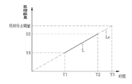
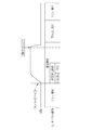
- the AEC unit 57 measures the accumulated dose in the daylighting field at two points at different times, and calculates the predicted time when the accumulated dose reaches the target dose by linear extrapolation from the data at these two points. Specifically, as shown in FIG. 10, the cumulative dose S1 of the daylighting field is measured at a time T1 when a predetermined time has elapsed after the daylighting field is set by the daylighting field setting unit 56, and the time when the predetermined time has passed since the time T1. The cumulative dose S2 is measured at T2. Then, the cumulative dose is the target at time T3 when the extended line Le of the straight line L connecting the cumulative dose S1, time T1 and the cumulative dose S2, time T2 intersects the irradiation stop threshold line converted from the target dose. Obtained as the time to reach the dose. The AEC unit 57 outputs an irradiation stop signal to the control unit 48 when determining that the accumulated dose of X-rays has reached the target dose at the obtained time T3.
- the irradiation signal I / F 25 of the radiation source control device 11 is wired or wirelessly connected to the irradiation signal I / F 58.
- the irradiation signal I / F 58 is a transmission / reception of a synchronization signal for synchronization control with the radiation source control device 11, specifically, reception of an irradiation start request signal from the radiation source control device 11, and an irradiation start request signal.
- the transmission of the irradiation permission signal, which is a response to, to the radiation source control device 11 is mediated.
- an irradiation stop signal output from the AEC unit 57 is received via the control unit 48 and transmitted to the radiation source control device 11.
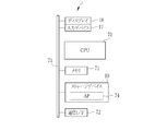
- the computer constituting the console 14 includes a CPU 70, a memory 71, and a communication I / F 72 in addition to the input device 17, the display 18, and the storage device 19. These are interconnected via a data bus 73.
- a control program and an application program (hereinafter referred to as AP) 74 are stored.
- the AP 74 is a program for causing the console 14 to execute various functions related to X-ray imaging, such as examination order and X-ray image display processing, X-ray image processing, and setting of imaging conditions.
- the memory 71 is a work memory for the CPU 70 to execute processing.
- the CPU 70 loads the control program stored in the storage device 19 into the memory 71 and executes processing according to the program, thereby comprehensively controlling each part of the computer.
- the communication I / F 72 is a network interface that performs wireless or wired transmission control with an external device such as a RIS, HIS, image storage server, and electronic cassette 13.
- the CPU 70 of the console 14 functions as an alignment processing unit 80, a masking processing unit 81, an input / output control unit 82, and an information acquisition unit 83 when the AP 74 is activated.
- the alignment processing unit 80 and the masking processing unit 81 perform various image processes such as an alignment process and a masking process described later on the X-ray image from the electronic cassette 13.
- the input / output control unit 82 reads screen data corresponding to the operation of the input device 17 from the storage device 19, and outputs various operation screens to the display 18 based on the read screen data.
- the input / output control unit 82 receives an input of an operation instruction from the input device 17 through a GUI (Graphical User Interface) arranged on the operation screen.
- the operation instructions include a search request for an X-ray image displayed on the display 18 and a processing request for causing the alignment processing unit 80 to execute alignment processing.
- the search request includes a search keyword for designating a desired X-ray image, such as a subject name and patient ID, an imaging date and time, an imaging region, and the like.
- the information acquisition unit 83 functions as an image acquisition unit and a lighting field information acquisition unit, acquires an X-ray image and lighting field information from the electronic cassette 13 via the communication I / F 72, and stores them in the storage device 19 Execute.
- the information acquisition unit 83 also has a function of searching / extracting the X-ray image and lighting field information corresponding to the specified search keyword from the storage device 19 in response to an X-ray image search request through the input device 17. Have.
- the information acquisition unit 83 transfers the extracted X-ray image to the alignment processing unit 80 or the input / output control unit 82.
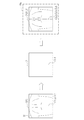
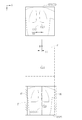
- the alignment processing unit 80 images the same imaging region of the same subject a plurality of times with a time interval, and a plurality of display images corresponding to the plurality of X-ray images obtained thereby are displayed. Alignment processing is performed to match the position of the subject drawn on each X-ray image. As shown in FIGS. 13A and 13B, when the position of the subject H positioned with respect to the imaging region 40 changes, the position of the subject H drawn in the X-ray images XP1 and XP2 naturally also changes. In FIG.
- the center line CL1 of the imaging region 40 and the center line CL2 of the subject coincide with each other, and the subject H depicted in the X-ray image XP1 is located at the center of the X-ray image XP1.
- the center line CL2 of the subject H and the center line CL3 of the X-ray image XP1 substantially coincide.
- the subject H is positioned toward the left side in the X direction, and the center line CL2 of the subject H is shifted to the left side in the X direction with respect to the center line CL1 of the imaging region 40.
- the subject H depicted in the X-ray image XP2 is also shifted to the left with respect to the center line CL3 of the X-ray image XP2.
- the input / output control unit 82 generates an image for display based on the X-ray image when displaying the X-ray image on the display 18.
- the input / output control unit 82 draws the image on a video memory and outputs the drawn image to the display 18 as a video signal.
- the resolution, the number of pixels, the display size, and the like of the image drawn on the video memory are determined according to the specifications of the display 18 and the AP 74 having an image display function, or according to the setting by the user.
- the display image is drawn on a video memory and output as a video signal in order to display an X-ray image on the display 18, and according to the specifications of the display 18 and the AP 74 having an image display function.
- the X-ray image is corrected for resolution, number of pixels, display size, and the like.
- a part of the memory 71 is used as the video memory.
- a dedicated video memory may be provided separately from the memory 71.
- the display frame F is a display frame for defining the display position and display size of the display images DXP1 and DXP2 in the screen 18a, and is set on the video memory.
- the display frame F set on the video memory and the display frame displayed on the screen 18a correspond to each other, for convenience of explanation, the same reference symbol F is attached as shown in FIGS. 14A and 14B. To explain.
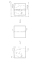
- the entire area of the X-ray image XP1 is drawn as the display image DXP1 in the display frame F on the video memory. Drawing is performed so that the center line CL3 of the X-ray image XP1 and the center line CL4 of the display frame F coincide.
- the center line CL3 of the X-ray image XP1 matches the center line CL2 of the subject H
- the center line CL3 of the X-ray image XP1 matches the center line CL4 of the display frame F.
- the center line CL2 of the subject H also coincides. Accordingly, the display image DXP1 is displayed on the screen 18a in a state where the center of the subject H is positioned at the center in the display frame F.
- the entire area of the X-ray image XP2 is drawn on the display frame F as the display image DXP2.
- the center line CL3 of the X-ray image XP2 and the center line CL4 of the display frame F coincide with each other.
- the X-ray image XP2 is different from the center line CL3 of the X-ray image XP2 and the center line CL2 of the subject H.
- the display image DXP2 is displayed in a state where the center of the subject H is shifted to one side from the center of the display frame F.
- the alignment processing unit 80 performs alignment processing in order to eliminate such misalignment.
- the alignment processing unit 80 sets one of a plurality of X-ray images (for example, X-ray images XP1 and XP2) as a reference image, and sets another X-ray image at the position of the lighting field of the set reference image.
- a plurality of X-ray images for example, X-ray images XP1 and XP2
- the reference image is, for example, an X-ray image obtained by first imaging among a plurality of X-ray images.
- the X-ray image obtained by the first imaging can be determined by the imaging date / time of the supplementary information. An X-ray image obtained by the latest imaging instead of the first time may be used.
- a plurality of X-ray images may be displayed on the display 18 and a reference image may be designated by the operator.
- a reference point for alignment may be set in advance for each imaging region.
- the operator can save time.
- the operator designates the reference image, an object in which the subject is well positioned is naturally selected, so that it becomes easier to observe a plurality of X-ray images after alignment.
- the input / output control unit 82 executes display processing for each of the X-ray images XP1 and XP2.
- the case where the X-ray image XP1 is set as the reference image BP and the X-ray image XP2 is set as the target image OP to be aligned with the reference image BP will be described as an example.
- the input / output control unit 82 sets the display frame F as shown in FIG.
- the display image DXP1 is generated so that the line CL4 matches.
- the alignment processing by the alignment processing unit 80 and the masking processing unit 81 are performed on the X-ray image XP2.
- the masking process is executed to generate the display image DXP2.
- the alignment processing unit 80 performs alignment processing based on the lighting field information I1 of the X-ray image XP1 and the lighting field information I2 of the X-ray image XP2.
- the alignment processing unit 80 receives the lighting field information I1 and I2 through the information acquisition unit 83.
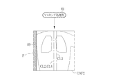
- the alignment processing unit 80 based on the lighting field information I1, I2, circumscribes the rectangular frame 85 (85a, 85b) of the lighting field A5 of each X-ray image XP1, XP2, and its center 86 ( 86a and 86b) are calculated.
- the circumscribed rectangular frame 85 is a rectangular frame that circumscribes the outer shape of the lighting field A5 and surrounds the entire lighting field A5. If there are a plurality of lighting fields A5 as in the left and right lung fields in this example, the coordinates of the circumscribed rectangular frame 85 and the center 86 are calculated for one of the lighting fields A5. In the figure, the coordinates of the circumscribed rectangular frame 85 and the center 86 of the left lung field are calculated.
- the alignment processing unit 80 displays the display frame based on the center 86a of the circumscribed rectangular frame 85a of the reference image BP (X-ray image XP1) and the center 86b of the circumscribed rectangular frame 85b of the target image OP (X-ray image XP2).
- a positional deviation amount SD (including the direction of deviation) of both in F is calculated. Since the lighting field information I1 and I2 is information reflecting the position of the subject H in the X-ray images XP1 and XP2, the positional deviation amount SD is the center line CL3 of the X-ray image XP2 and the center line of the subject H. This corresponds to the shift amount of CL2.
- the change rate of the size (reduction rate or enlargement)
- the positional deviation amount SD in the X-ray image XP2 and the positional deviation amount SD in the display frame F change according to the ratio. In this example, an example in which the size is not changed will be described.
- the alignment processing unit 80 displaces the center line CL3 of the X-ray image XP2 by the displacement amount SD with respect to the center line CL4 of the display frame F, as shown in FIG.
- the center line CL2 of the subject H is shifted, but the display image DXP2 is also displayed by performing the alignment process. Similar to the image DXP1, the center line CL2 of the subject H coincides with the center line CL4 of the display frame F.
- the subject H in the display image DXP2 of the X-ray image XP2 (target image OP) is positioned at the center in the same manner as the subject H in the display image DXP1 of the X-ray image XP1 (reference image BP).
- the positional deviation between the position of the subject H in the display image DXP1 and the position of the subject H in the display image DXP2 is eliminated.
- the case where the subject in the target image OP (X-ray image XP2) is displaced only in the X direction with respect to the subject H in the reference image BP (X-ray image XP1) is illustrated.
- the position shift amount SD is obtained based on the lighting field information I1 and I2, and the alignment process is executed.
- a positional shift amount SD in the Y direction is obtained.
- a positional shift amount SD obtained by vector composition of the positional shift components in both the X and Y directions is obtained based on the lighting field information I1 and I2.
- the positional deviation of the subject H in the display image is eliminated.
- the center of gravity of the lighting field specified in a form faithfully along the shape of the region of interest and its coordinates may be obtained and used as the reference point for alignment.
- the display frame F has a blank portion 87 having no image information; A protruding portion 88 in which a part of the display image DXP2 protrudes from the display frame F is formed.
- the masking processing unit 81 performs masking processing, for example, blackening processing on the blank portion 87 and fills the blank portion 87 with a black image 89.
- the protruding portion 88 is not displayed on the display 18 because it is out of the display frame F. Note that masking processing may be performed with an intermediate color such as gray or white instead of blackening processing.
- the alignment processing unit 80 and the masking processing unit 81 When there are a plurality of target images OP, the alignment processing unit 80 and the masking processing unit 81 perform alignment processing and masking processing on the plurality of target images OP.
- the alignment processing unit 80 and the masking processing unit 81 thus generate display images of a plurality of X-ray images for comparative interpretation.
- the CPU 70 causes the storage device 19 to store the processed display image in association with the corresponding X-ray image.
- information on the positional deviation amount SD in the alignment process may be stored in the storage device 19.
- the input / output control unit 82 displays a comparative interpretation window 95 of the form shown in FIG. 20 on the screen 18a of the display 18 at the time of comparative interpretation.
- the display images DXP1 and DXP2 are displayed in the comparative interpretation window 95.
- the comparative interpretation window 95 is provided with two sub-windows 96a and 96b corresponding to the display frame F in the screen 18a.
- two display images DXP1 (image 1) and DXP2 (image 2) are displayed side by side along with the shooting date and time.
- the positional deviation of the subject H is eliminated by the alignment process. Further, the left end is filled with a black image 89 by masking processing.
- Such a comparative interpretation window 95 allows the operator to observe the two display images DXP1 and DXP2 side by side.
- Control bars 97a and 97b are provided below the sub-windows 96a and 96b.
- the display images displayed on the sub-windows 96a and 96b can be switched by operating the control bars 97a and 97b.
- perform automatic switching playback that switches display images at regular time intervals, pause or stop automatic switching playback, and frame-reverse and frame-by-frame switching of the display image one frame at a time during the stop You can also.
- the number of images displayed side by side is not limited to two, and may be three or more.
- only one sub window may be provided and a plurality of display images may be switched and displayed in one sub window. Further, a plurality of display images may be superimposed and displayed. Of course, you may enable it to select these various display forms.
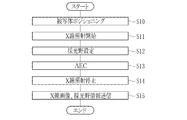
- FIG. 22 when X-ray imaging is performed in the X-ray imaging system 2, first, the subject is set at a predetermined imaging position on any of the imaging tables 15 and 16 in the standing position and the standing position, and the electronic cassette 13 Positioning is performed by adjusting the height and the horizontal position so as to align the position with the imaging region of the subject (S10). Then, the height, horizontal position, and irradiation field size of the X-ray source 10 are adjusted according to the position of the electronic cassette 13 and the size of the imaging region. Next, imaging conditions are set in the radiation source control device 11 and the console 14. Further, the X-ray angle range and SID are input to the console 14. If these X-ray angle ranges and SID values are unchanged and have already been input, this input procedure is omitted.
- the irradiation switch 12 When the preparation for photographing is completed, the irradiation switch 12 is pressed halfway by the operator. When the irradiation switch 12 is half-pressed, the radiation source control device 11 issues a warm-up start signal to the high voltage generator 21 to cause the X-ray source 10 to start warm-up. Further, the radiation source control device 11 transmits an irradiation start request signal to the electronic cassette 13.
- the sensor panel 30 of the electronic cassette 13 before X-ray imaging, the sensor panel 30 of the electronic cassette 13 repeatedly performs a resetting operation and waits for an irradiation start request signal.
- the sensor panel 30 transmits an irradiation permission signal to the radiation source control device 11 after performing a state check.
- the sensor panel 30 finishes the reset operation, and starts the accumulation operation and the dose detection operation in parallel therewith.
- the radiation source control device 11 When the irradiation control signal is received from the sensor panel 30 and the irradiation switch 12 is fully pressed, the radiation source control device 11 issues an irradiation start signal to the high voltage generator 21 and supplies the X-ray source 10 with X. Irradiation is started (S11). X-rays emitted from the X-ray source 10 pass through the subject and enter the sensor panel 30.
- the charge generated in the normal pixel 41 a is accumulated in the photoelectric conversion unit 42, but the charge generated in the detection pixel 41 b flows into the capacitor 49 b of the integration amplifier 49 from the signal line 45 because the TFT 43 is short-circuited. To do.
- the charge generated in the detection pixel 41b is repeatedly read at a predetermined sampling period. The dose signal obtained by this sampling is stored in the memory 54, and is read from the memory 54 to the lighting field setting unit 56 every sampling.
- the lighting field setting unit 56 first picks up the dose signal of the detection pixel 41b existing in the irradiation field out of the dose signals recorded in the memory 54 based on the information on the size of the irradiation field sent from the console 14. Is done. Next, the dose signal of the detection pixel 41b existing in the subject region is picked up by comparing the dose signal of the detection pixel 41b existing in the irradiation field with the threshold for specifying the missing region provided from the console 14. Finally, a daylighting field is set from the subject area by the image recognition technique (S12). In FIG. 21, the daylighting field is specified during the period when the dose is increasing immediately after the start of X-ray irradiation. However, after the dose has settled to a constant value as described above, the daylighting field is specified. Also good.
- the AEC unit 57 reads out the dose signal from the detection pixel 41b existing in the daylight field set by the daylight field setting unit 56 from the memory 54, and calculates the cumulative dose of the daylight field based on this. Then, the AEC unit 57 calculates a time T3 at which the accumulated dose is predicted to reach the target dose by linear extrapolation based on the accumulated doses S1 and S2 of the lighting field measured at two points of different times T1 and T2. S13). The AEC unit 57 outputs an irradiation stop signal to the control unit 48 when the obtained time T3 is reached. The irradiation stop signal is transmitted to the radiation source control device 11. In response to the irradiation stop signal, the radiation source control device 11 stops the X-ray irradiation by the X-ray source 10 (S14).
- the accumulation operation is performed in the normal pixel 41a after transmitting the irradiation permission signal.
- the operation of the sensor panel 30 is shifted from the accumulation operation to the read operation.
- image data representing one X-ray image is output to the memory 54.
- the sensor panel 30 returns to the reset operation.
- the dose does not become zero immediately after the irradiation stop signal is output, but a wave tail occurs. In order to absorb this wave tail, in this example, the storage operation is shifted to the reading operation after a predetermined time has elapsed since the irradiation stop signal was transmitted.
- Various image processing is performed on the X-ray image output to the memory 54 by the read operation by the various image processing circuits of the control unit 48.
- the image-processed X-ray image is transmitted to the console 14 in association with the daylighting field information (S15). This completes one X-ray imaging.
- the first X-ray imaging is performed before the treatment, and after the treatment, the same subject H (patient) is the same after 3 days, 1 week, 1 month, etc.
- the second X-ray imaging is performed for the imaging region.
- the X-ray image and the lighting field information transmitted from the electronic cassette 13 are received by the communication I / F 72 and stored in the storage device 19 under the control of the information acquisition unit 83.
- a plurality of X-ray images obtained by imaging the same imaging region of the same subject a plurality of times at intervals are also stored in the storage device 19.
- a search request for a plurality of X-ray images of the same imaging region of the same subject is input through the input device 17, and a processing request for executing alignment processing is performed. Is input (YES in S20).
- the information acquisition unit 83 extracts a plurality of X-ray images and lighting field information corresponding to the search request.
- the information acquisition unit 83 passes the X-ray image set as the reference image among the extracted plurality of X-ray images to the input / output control unit 82.
- the extracted plurality of X-ray images and the lighting field information of each X-ray image are passed to the alignment processing unit 80 (S21).
- the input / output control unit 82 simply displays the display image by matching the center line of the X-ray image with the center line of the display frame. Generate.
- the alignment processing unit 80 executes the alignment process in the manner shown in FIGS. 17 and 18, and the subject in the display image of the target image OP. Is matched with the position of the subject in the display image of the reference image XP (S22). Further, as shown in FIG. 19, in the masking processing unit 81, masking processing is performed on the display image of the target image after alignment (S23). By doing so, the appearance of the display image of the target image OP is improved, and comparative interpretation is facilitated. In particular, when a blackening process is performed as a masking process, a subject drawn in white or gray is relatively conspicuous, and the visibility of the subject is improved.
- the display image of the target image OP that has been subjected to various processes is stored in the storage device 19 in association with the X-ray image before the alignment process (S24). For this reason, once the alignment process has been completed, the subsequent X-ray image display image stored in the storage device 19 may be read when performing comparative interpretation thereafter. Is no longer necessary.
- the input / output control unit 82 displays the display image of the reference image SP and the display image of the target image OP on which various processes have been performed on the display 18 in a comparative interpretation window 95 so as to allow comparative interpretation (S25). Even if the subject positioning is deviated for each photographing, the positions of the light fields of the plurality of X-ray images are matched by the alignment process, so that comparative interpretation is easy.
- an image analysis process is performed on an X-ray image output after imaging to identify a region of interest, and the identified region of interest is positioned on a plurality of X-ray images.
- a method of using as a mark for alignment is also conceivable.
- the region of interest has already been specified by setting the daylighting field when taking an X-ray image. Since the alignment of a plurality of X-ray images is performed based on the already-explained lighting field information, it is not necessary to specify the region of interest after the X-ray image is output, and the time required for the alignment process can be shortened.
- the daylight field set by the daylight field setting unit 56 for AEC is used for alignment of a plurality of X-ray images, the utility value of the technique for automatically setting the daylight field during the radiographing, and thus the field of view, is useful. Rise.
- the present invention takes advantage of the fact that there is no need to pay attention to subject positioning in the technology for automatically setting the daylighting field during X-ray irradiation, and as a result, the relative positional relationship between the subject and the electronic cassette 13 is The problem of falling apart is dealt with by an alignment process based on daylighting field information.
- the electronic cassette 13 when the electronic cassette 13 is set on the photographing bases 15 and 16, in order to stabilize the positioning of the subject, the normal photographing bases 15 and 16 are provided with catch bars and chin rests for grasping the subject. Even if the positioning is not strictly enforced, the positioning will not deviate so much.
- the electronic cassette 13 when the electronic cassette 13 is used alone by placing it on a bed on which the subject lies, or by placing the electronic cassette 13 on the subject itself, there is no device such as a holding bar or a chin, so the positioning is likely to be greatly shifted. Therefore, if the present invention is applied to a plurality of X-ray images photographed using the electronic cassette 13 alone, a more advantageous effect can be expected.
- the alignment process by the parallel movement on the XY plane is exemplified, but the alignment process by the rotation on the XY plane or the alignment process by the rotation of the XY plane itself may be incorporated.
- the alignment process by the rotation on the XY plane or the alignment process by the rotation of the XY plane itself may be incorporated.
- the display image of the target image is rotated and aligned so as to eliminate such distortion and shift.
- at least two points are necessary as alignment reference points. For example, when the left and right lung fields are set as the lighting fields, the center of each circumscribed rectangular frame of the left and right lung fields is set as the reference point.
- the display frame setting method may be a method of setting coordinates representing the positions of the four sides that are the outer periphery of the display frame, or an origin defined by the coordinate information and an area or number of pixels based on the origin.
- a method of setting may be used.
- the location for storing images may be other than the console 14, for example, an image storage server that can be connected to the console 14 via a network.
- the console 14 accesses the image storage server through the network, and the console 14 reads out the X-ray image to be followed up.
- the detection pixel 41b in which the source electrode and the drain electrode of the TFT 43 are short-circuited is illustrated, but a pixel in which the TFT 43 is not provided and the photoelectric conversion unit 42 is directly connected to the signal line 45 may be used as the detection pixel.
- the detection pixel 41c shown in FIG. the same code
- the sensor panel 110 has a detection pixel 41c to which a TFT 113 driven by a scanning line 111 and a gate driver 112 different from the scanning line 44 and gate driver 46 for driving the TFT 43 of the normal pixel 41a are connected. Since the detection pixel 41c is connected to the TFT 113, the normal pixel 41a in the same row can read out the charge even when the TFT 43 is turned off and during the accumulation operation.
- the gate driver 112 controls the gate pulses GG1, GG2, GG3,..., GGK (K ⁇ N) that drive the TFTs 113 in the same row at a predetermined interval under the control of the control unit 48.
- the scanning lines 111 are sequentially activated row by row, and the TFTs 113 connected to the scanning lines 111 are sequentially turned on row by row.
- the time for turning on is defined by the pulse width of the gate pulse, and the TFT 113 returns to the off state when the time defined by the pulse width elapses.
- the charge generated in the photoelectric conversion unit 42 of the detection pixel 41 c flows into the capacitor 49 b of the integration amplifier 49 via the signal line 45 while the TFT 113 is in an on state regardless of whether the TFT 43 is on or off.
- the charge from the detection pixel 41c accumulated in the integrating amplifier 49 is output to the A / D 52 and converted into a dose signal by the A / D 52. Subsequent processing is the same as that in the above embodiment, and thus description thereof is omitted.
- the dose signal sampling period is from when the TFT 113 is turned off to start accumulating charges in the detection pixel 41 c until the gate pulse is applied to the TFT 113 and the accumulated charge in the detection pixel 41 c is output to the signal line 45. In other words, this is the charge accumulation period of the detection pixel 41c.
- gate pulses GG1, GG2, GG3,..., GGK are given to the TFTs 113 in each row, dose signals from all the detection pixels 41b are recorded in the memory 54.
- the dose is detected by sampling the current of the bias line connected to a specific pixel by using the current based on the charge generated in the pixel on the bias line that supplies the bias voltage to each pixel of the sensor panel. May be.
- the pixel that samples the current of the bias line becomes the dose detection sensor.
- the dose may be detected by sampling the leak current flowing out from the pixel.
- the pixel that samples the leak current is the dose detection sensor.
- a dose detection sensor having a different configuration and independent output from the pixel may be provided in the imaging region.
- a TFT type sensor panel is illustrated, but a CMOS type sensor panel may be used.
- CMOS type so-called nondestructive reading is possible in which signal charges accumulated in the pixels are read as voltage signals through amplifiers provided in the pixels without flowing out to the signal lines. Therefore, even during the accumulation operation, the dose can be measured by selecting an arbitrary pixel in the imaging region and reading the voltage signal from the pixel. Therefore, when a CMOS type sensor panel is used, all pixels can be used as detection pixels without providing pixels dedicated to dose detection like the detection pixels.
- the time when the accumulated dose in the lighting field is predicted to reach the irradiation stop threshold is calculated, and when the calculated predicted time is reached, the irradiation stop signal is transmitted to the radiation source control device.
- the time information itself may be transmitted to the radiation source control device.
- the radiation source control device measures the X-ray irradiation time, and stops the X-ray irradiation when the irradiation time reaches the predicted time.
- the cumulative dose in the lighting field and the irradiation stop threshold are compared for each sampling of the dose signal, and when the cumulative dose in the lighting field actually reaches the irradiation stop threshold, the irradiation stop signal is sent to the radiation source controller. Also good.
- one imaging is performed by one X-ray irradiation.
- one imaging is performed twice, that is, the main irradiation and the pre-irradiation performed at a dose lower than the main irradiation before the main irradiation.
- the present invention can also be applied to a case where a lighting field is set based on a dose signal output during pre-irradiation divided into X-ray irradiation, and AEC is performed in the lighting field set by pre-irradiation.
- the alignment processing and the display of a plurality of X-ray images are all performed by the console.
- the console may be connected to a terminal other than the console, for example, an image display terminal used by a doctor who performs image diagnosis.
- a similar alignment processing function and a display function for a plurality of X-ray images may be provided.
- the console only performs alignment processing, and the processing result is stored in an image storage server connected to the console and the image display terminal via a network, and the image storage server is accessed from the image display terminal to display the alignment processing result. Reading to the image display terminal and displaying a plurality of X-ray images may be performed by the image display terminal. That is, the alignment processing unit, the masking processing unit, the storage unit, and the like constituting the radiographic image processing apparatus of the present invention may be provided in one apparatus or distributed among a plurality of apparatuses. It may be.
- an imaging control device that executes a part of the function of controlling the electronic cassette included in the console may be connected between the electronic cassette and the console.
- the present invention is not limited to an electronic cassette that is a portable X-ray image detection device, and may be applied to an X-ray image detection device that is installed on an imaging table.
- the present invention can be applied not only to X-rays but also to other radiation such as ⁇ rays as an imaging target.
- the present invention extends to a program form and a storage medium storing the program.
Landscapes
- Health & Medical Sciences (AREA)
- Life Sciences & Earth Sciences (AREA)
- Engineering & Computer Science (AREA)
- Medical Informatics (AREA)
- Physics & Mathematics (AREA)
- Biomedical Technology (AREA)
- Molecular Biology (AREA)
- Biophysics (AREA)
- Nuclear Medicine, Radiotherapy & Molecular Imaging (AREA)
- Optics & Photonics (AREA)
- Pathology (AREA)
- Radiology & Medical Imaging (AREA)
- Veterinary Medicine (AREA)
- Heart & Thoracic Surgery (AREA)
- High Energy & Nuclear Physics (AREA)
- Surgery (AREA)
- Animal Behavior & Ethology (AREA)
- General Health & Medical Sciences (AREA)
- Public Health (AREA)
- Computer Vision & Pattern Recognition (AREA)
- General Physics & Mathematics (AREA)
- Theoretical Computer Science (AREA)
- Human Computer Interaction (AREA)
- Mathematical Physics (AREA)
- Apparatus For Radiation Diagnosis (AREA)
Abstract
撮影中に採光野を自動設定する場合でも、簡便な方法で経過観察に適した表示用画像を得ることができる放射線画像処理装置を提供する。 電子カセッテには、AECのために線量を検出する検出画素の領域である採光野を、検出画素からの線量信号に基づきX線の照射中に自動的に設定する採光野設定部が設けられている。コンソールは、採光野設定部で設定された採光野情報とX線画像を情報取得部で取得する。位置合わせ処理部は、採光野情報に基づき、同一の被写体の同一の撮影部位を、時間を空けて複数回撮影して得られた複数枚のX線画像に対応する複数枚の表示用画像について、複数枚のX線画像に描出された被写体の位置を一致させる位置合わせを行う。
Description
本発明は、放射線画像処理装置および方法、並びに放射線撮影装置に関する。
医療分野において、放射線、例えばX線を利用したX線撮影システムが知られている。X線撮影システムは、X線を発生するX線発生装置と、被写体(患者)を透過したX線で形成されるX線画像を撮影するX線撮影装置とを備えている。X線発生装置は、X線を被写体に向けて照射するX線源、X線源の駆動を制御する線源制御装置、およびX線源を動作させるための指示を線源制御装置に入力する照射スイッチを有している。X線撮影装置は、被写体を透過したX線に応じたX線画像を検出するX線画像検出装置、およびX線画像検出装置の駆動制御、X線画像に対する画像処理、X線画像の保存、表示を行うコンソールを有している。
X線画像検出装置は、フラットパネルディテクタ(FPD;flat panel detector)とも呼ばれるセンサーパネルを備え、X線画像を電子的に検出する。このセンサーパネルは、X線の入射量に応じた信号電荷を蓄積する複数の画素が配置された撮像領域を有する。画素は、電荷を発生してこれを蓄積する光電変換部、およびTFTなどのスイッチング素子を備える。センサーパネルは、スイッチング素子のオン動作に応じて、画素の列毎に設けられた信号線を通じて各画素の光電変換部に蓄積された信号電荷を信号処理回路に読み出し、信号処理回路で信号電荷を電圧信号に変換することでX線画像を電気的に検出する。
X線撮影システムにおいては、被写体への被曝量を抑えつつ適正な画質のX線画像を得るために、X線の照射中にX線の線量を検出して、線量の積算値である累積線量が目標線量に達したときにX線源によるX線の照射を停止させるAEC(Automatic Exposure Control、自動露出制御)が行われる場合がある。X線源が照射するX線の累積線量は、X線の照射時間とX線源が単位時間当たりに照射するX線の線量を規定する管電流との積である管電流時間積(mAs値)によって決まる。照射時間や管電流などの撮影条件は、胸部や頭部といった被写体の撮影部位、性別、年齢などによっておおよその推奨値はあるものの、被写体の体格などの個人差によってX線の透過率が変わるため、より適切な画質を得るためにAECが行われる。
AECを行う場合には、被写体を透過したX線の線量を検出する線量検出装置が用いられる。線量検出装置としては、X線画像検出装置と組み合わせて使用することが可能なイオンチャンバーが知られている。イオンチャンバーは、例えば、胸部撮影の際に左右の肺野にあたる対称な2つの上部位置とその下部位置の合計3箇所に配置された線量検出センサを有しており、X線画像検出装置の前面または背面を覆うように取り付けられる。例えば胸部撮影の際には、撮影前の準備作業として、上部位置の2つの線量検出センサが、AECにおける線量検出の基準となる採光野として選択される。そして、この選択された採光野と被写体の左右の肺野とが対向するように被写体とX線画像検出装置との相対的な位置関係を合わせるポジショニングが行われる。ポジショニングが正確に行われなかった場合は、肺野と採光野の位置がずれて適正なAECができないので、ポジショニングは慎重に行われる。こうしたポジショニングが終了した後に、撮影が開始される。撮影中は、採光野として選択された線量検出センサから出力される線量信号に基づきX線の照射停止のタイミングが判定される。
また、線量検出装置の機能をセンサーパネルに一体化したものも知られている(特開平07-201490号公報、特開2002-000590号公報参照)。特開平07-201490号公報、特開2002-000590号公報に記載のセンサーパネルは、X線画像を検出するための撮像領域内の画素を線量検出センサとして動作させるものであり、複数の画素の中から任意の画素を採光野として選択することが可能である。特開平07-201490号公報、特開2002-000590号公報のセンサーパネルの線量検出機能を使用してAECを行う場合においても、イオンチャンバーを使用する場合と同様に、撮影前の準備作業として採光野の選択と選択された採光野に応じた被写体のポジショニングとを行った後に、撮影が開始される。
発明者らは、特開平07-201490号公報、特開2002-000590号公報に記載されているセンサーパネルの画素を線量検出センサとして動作させる技術をさらに推し進めて、撮影中に採光野を自動設定する技術を検討している。より具体的には、センサーパネルの画素のうちの一部を線量検出センサとして機能する検出画素とし、これを撮像領域に分散して配置する。そして、撮影中に検出画素から出力される線量信号に基づき採光野を設定する。例えば胸部撮影では、肺野の位置に対向する検出画素の出力は肺野に隣接する他の部分と比べて高出力となるので、線量信号が他の部分と比べて高出力の検出画素を採光野として自動設定する。その後、採光野として設定された検出画素からの線量信号に基づきAECを行う。この技術によれば、従来撮影の準備作業として必要であった採光野の選択が不要となる。また、被写体とX線画像検出装置との相対位置関係に応じて採光野が自動設定されるため、被写体のポジショニングを従来ほど慎重に行う必要もなくなる。
ところで、画像診断においては、例えば手術前と手術後など、同一の被写体の同一の撮影部位を、時間を空けて複数回撮影して得られた複数枚のX線画像を比較読影する経過観察が行われる。経過観察においては、ディスプレイの表示画面に複数枚のX線画像を並列表示したり、あるいは、1枚ずつ切り替え表示するなどして、複数枚のX線画像を比較読影可能に表示する。
例えば、手術前のX線画像では被写体がほぼ中央に位置しているのに対して、手術後のX線画像では被写体が右または左に寄っているなど、複数枚のX線画像に描出される被写体の位置が一定でないと比較読影がやりにくい。このため、経過観察に利用される複数枚のX線画像間では、X線画像内の被写体の位置が一定であることが好ましい。
ところが、発明者らが目下検討中の撮影中に採光野を自動設定する技術を採用した場合、従来のように被写体のポジショニングに気を使う必要がない反面、経過観察を目的とした複数回の撮影において被写体とX線画像検出装置との相対位置関係がばらばらになり、結果として複数枚のX線画像間で被写体の位置がずれるおそれがあった。
この問題の解決策として、複数枚のX線画像に対してパターン認識などの画像解析を施して各X線画像内の被写体の位置を認識し、認識した被写体の位置に基づいて、各X線画像の被写体の位置を一致させる位置合わせ処理を行うことが考えられる。しかし、画像解析によってX線画像内の被写体の位置を認識する方法は処理が複雑で時間も掛かる。そこで、上記問題に対してより簡便な解決策が求められていた。
本発明は、撮影中に採光野を自動設定する技術を用いた場合においても、簡便な方法で経過観察に適した表示用画像を得ることができる放射線画像処理装置および方法、並びに放射線撮影装置を提供することを目的とする。
上記目的を達成するために、本発明の放射線画像処理装置は、複数の画素が配置された撮像領域を有し、被写体の放射線画像を検出する放射線画像検出装置を用い、同一の被写体の同一の撮影部位を、時間を空けて複数回撮影して得られた複数枚の放射線画像に対して画像処理を施す放射線画像処理装置であり、画像取得部、採光野情報取得部、および位置合わせ処理部を備える。画像取得部は、複数枚の放射線画像を取得する。採光野情報取得部は、放射線画像検出装置が撮影時に実行するAECの際に、ポジショニングされる被写体の位置に応じて撮像領域内に自動設定され、複数枚の放射線画像のそれぞれに関連付けて記録された採光野の位置を表す採光野情報を取得する。位置合わせ処理部は、採光野情報取得部で取得した採光野情報に基づき、複数枚の放射線画像に対応する複数枚の表示用画像について、複数枚の放射線画像のそれぞれに描出された被写体の位置を一致させるための位置合わせ処理を実行する。
位置合わせ処理部は、複数枚の放射線画像の採光野の位置を合わせることにより、複数枚の表示用画像内における被写体の位置を一致させることが好ましい。
採光野情報は、放射線画像内における採光野の位置を表す座標情報が好ましい。
位置合わせ処理部は、採光野内から位置合わせの基準点を求めて、位置合わせ処理を実行することが好ましい。基準点は、例えば採光野の外形と外接し、採光野の全体を取り囲む外接矩形枠の中心である。
位置合わせ処理部は、複数枚の放射線画像のうちの1枚を基準画像とし、基準画像の採光野の位置を基準として位置合わせ処理を実行することが好ましい。基準画像は、マニュアル設定または自動設定により複数枚の放射線画像の中から選択された1枚の放射線画像である。
位置合わせ処理部は、表示用画像を描画する表示枠に対して、表示用画像の描画位置を変位させることにより位置合わせ処理を実行することが好ましい。描画位置の変位により生じた空白部分に対してマスキング処理を施すマスキング処理部を備えることが好ましい。
位置合わせ処理後の表示用画像、または位置合わせ処理における描画位置のずらし量を、放射線画像と関連付けて記憶する記憶部を備えることが好ましい。
本発明の放射線画像処理方法は、複数の画素が配置された撮像領域を有し、被写体の放射線画像を検出する放射線画像検出装置を用い、同一の被写体の同一の撮影部位を、時間を空けて複数回撮影して得られた複数枚の放射線画像に対して画像処理を施す放射線画像処理方法であり、画像取得ステップ、採光野情報取得ステップ、および位置合わせ処理ステップを備える。画像取得ステップは、複数枚の放射線画像を画像取得部で取得する。採光野情報取得ステップは、放射線画像検出装置が撮影時に実行するAECの際に、ポジショニングされる被写体の位置に応じて撮像領域内に自動設定され、複数枚の放射線画像のそれぞれに関連付けて記録された採光野の位置を表す採光野情報を採光野情報取得部で取得する。位置合わせ処理ステップは、採光野情報取得ステップで取得した採光野情報に基づき、複数枚の放射線画像に対応する複数枚の表示用画像について、複数枚の放射線画像のそれぞれに描出された被写体の位置を一致させるための位置合わせ処理を位置合わせ処理部で実行する。
本発明の放射線撮影装置は、複数の画素が配置された撮像領域を有し、被写体の放射線画像を検出する放射線画像検出装置と、放射線画像検出装置を用い、同一の被写体の同一の撮影部位を、時間を空けて複数回撮影して得られた複数枚の放射線画像に対して画像処理を施す放射線画像処理装置とを備える。放射線画像処理装置は、画像取得部、採光野情報取得部、および位置合わせ処理部を備える。画像取得部は、複数枚の放射線画像を取得する。採光野情報取得部は、放射線画像検出装置が撮影時に実行するAECの際に、ポジショニングされる被写体の位置に応じて撮像領域内に自動設定され、複数枚の放射線画像のそれぞれに関連付けて記録された採光野の位置を表す採光野情報を取得する。位置合わせ処理部は、採光野情報取得部で取得した採光野情報に基づき、複数枚の放射線画像に対応する複数枚の表示用画像について、複数枚の放射線画像のそれぞれに描出された被写体の位置を一致させるための位置合わせ処理を実行する。
放射線画像検出装置は、パネル部、複数の線量検出センサ、採光野設定部、およびAEC部を有することが好ましい。パネル部には、撮像領域が形成される。複数の線量検出センサは、撮像領域に分散して配置され、撮像領域に到達する放射線の線量を検出してこれに応じた線量信号を出力する。採光野設定部は、撮影中に複数の線量検出センサから出力される線量信号に基づいて採光野を自動的に設定する。AEC部は、採光野設定部で設定された採光野内の線量検出センサから出力される線量信号に基づいてAECを行う。
本発明によれば、撮影中に自動設定された採光野情報に基づき、同一の被写体の同一の撮影部位を、時間を空けて複数回撮影して得られた複数枚の放射線画像に対応する表示用画像の位置合わせ処理を行うので、撮影中に採光野を自動設定する技術を用いた場合においても、簡便な方法で経過観察に適した表示用画像を得ることができる。
図1において、X線撮影システム2は、X線源10と、X線源10の動作を制御する線源制御装置11と、X線源10へのウォームアップ開始とX線の照射開始を指示するための照射スイッチ12と、X線の累積線量が目標線量に達したときにX線の照射を停止させるAEC機能をもち、被写体(患者)を透過したX線を検出してX線画像を出力する電子カセッテ13と、電子カセッテ13の動作制御やX線画像の表示処理を担う、本発明の放射線画像処理装置に相当するコンソール14と、被写体を立位姿勢で撮影するための立位撮影台15と、臥位姿勢で撮影するための臥位撮影台16とを有する。X線源10、線源制御装置11、および照射スイッチ12はX線発生装置2a、電子カセッテ13、およびコンソール14はX線撮影装置2bをそれぞれ構成する。この他にもX線源10を所望の方向および位置にセットするための線源移動装置(図示せず)が設けられており、X線源10は立位撮影台15および臥位撮影台16で共用される。
X線源10は、X線管と、X線管が放射するX線の照射野を限定する照射野限定器(コリメータ)とを有する。X線管は、熱電子を放出するフィラメントである陰極と、陰極から放出された熱電子が衝突してX線を放射する陽極(ターゲット)とを有している。ウォームアップ開始の指示があると陽極が回転を開始し、規定の回転数となったらウォームアップが終了する。照射野限定器は、例えば、X線を遮蔽する4枚の鉛板を四角形の各辺上に配置し、X線を透過させる四角形の照射開口が中央に形成されたものであり、鉛板の位置を移動することで照射開口の大きさを変化させて、出射されるX線の角度範囲を縦横の2方向で調整する。これにより、X線の照射野が限定される。
コンソール14は、有線方式や無線方式により電子カセッテ13と通信可能に接続されており、キーボードなどの入力デバイス17を介した放射線技師などのオペレータからの入力操作に応じて電子カセッテ13の動作を制御する。電子カセッテ13からのX線画像はコンソール14のディスプレイ18に表示される他、そのデータがコンソール14内のハードディスクやメモリといったストレージデバイス19、あるいはコンソール14とネットワーク接続された画像蓄積サーバなどに記憶される。
コンソール14は、被写体の氏名、性別、年齢、撮影部位、撮影目的などの情報が含まれる検査オーダの入力を受け付けて、検査オーダをディスプレイ18に表示する。検査オーダは、HIS(病院情報システム)やRIS(放射線情報システム)などの患者情報や放射線検査に係る検査情報を管理する外部システムから入力されるか、オペレータにより手動入力される。検査オーダには、頭部、胸部、腹部、手、指などの撮影部位の項目がある。撮影部位には、正面、側面、斜位、PA(X線を被写体の背面から照射)、AP(X線を被写体の正面から照射)などの撮影方向も含まれる。オペレータは、検査オーダの内容をディスプレイ18で確認し、その内容に応じた撮影条件をディスプレイ18に映された操作画面を通じて入力デバイス17で入力する。
図2において、ストレージデバイス19には、複数の撮影条件が予め記録された撮影条件テーブル20が格納されている。撮影条件には、撮影部位、X線源10が照射するX線のエネルギースペクトルを決める管電圧(単位;kV)、単位時間当たりの照射量を決める管電流(単位;mA)、X線の照射時間(単位;s)、および照射停止閾値が含まれる。管電流と照射時間の積でX線の累積線量が決まるため、撮影条件としては、管電流と照射時間のそれぞれの値を個別に入力する代わりに、両者の積である管電流時間積(mAs値)の値が入力される場合もある。これら管電圧、管電流、照射時間の値を微調整することも可能である。照射停止閾値は、AEC部57(図5参照)がX線の照射停止を判定するための情報である。なお、図2では撮影部位として胸部AP、胸部PAのみを例示しているが、実際には頭部、腹部、脚部といった他の撮影部位に対応する撮影条件や、それに応じた照射停止閾値も記憶されている。
コンソール14には、撮影条件とともに、X線源10の照射野限定器に設定された縦横2方向のX線の角度範囲、および電子カセッテ13の撮像領域40(図5参照)の位置からX線管の焦点の位置までの距離であるSID(Source Image Distance)の情報が入力デバイス17で入力される。
図3において、線源制御装置11は、トランスによって入力電圧を昇圧して高圧の管電圧を発生し、高電圧ケーブルを通じてX線源10に供給する高電圧発生器21と、X線源10に与える管電圧および管電流と、X線の照射時間を制御する制御部22と、メモリ23と、タッチパネル24と、電子カセッテ13との信号の送受信を媒介する照射信号I/F25とを備える。
制御部22には照射スイッチ12とメモリ23とタッチパネル24が接続されている。照射スイッチ12は、制御部22に対して指示を入力するスイッチであり、2段階の押圧操作が可能である。制御部22は、照射スイッチ12が1段階押し(半押し)されると、高電圧発生器21に対してウォームアップ開始信号を発して、X線源10にウォームアップを開始させる。
照射スイッチ12が1段階押し(半押し)されると、制御部22は電子カセッテ13との間で同期信号の送受信による同期制御を行う。さらに照射スイッチ12が2段階押し(全押し)されると、制御部22は照射開始信号を高電圧発生器21に発して、X線源10によるX線の照射を開始させる。
メモリ23は、管電圧、管電流、照射時間などの撮影条件を予め数種類格納している。撮影条件はタッチパネル24を通じてオペレータにより手動で設定される。タッチパネル24には、メモリ23から読み出された撮影条件が複数種類表示される。表示された撮影条件の中から、コンソール14に入力した撮影条件と同じ撮影条件をオペレータが選択することにより、線源制御装置11に対して撮影条件が設定される。コンソール14の場合と同様、撮影条件の値を微調整することも可能である。制御部22は、設定された照射時間となったらX線の照射を停止させるためのタイマー26を内蔵している。なお、線源制御装置11とコンソール14とを接続し、コンソール14に入力された撮影条件を線源制御装置11に送信することで線源制御装置11の撮影条件の設定を自動化してもよい。
電子カセッテ13のAEC機能を使用する場合の照射時間は、目標線量に達してAEC機能による照射停止の判断がされる前にX線の照射が終了して線量不足に陥ることを防ぐため、余裕を持った値が設定される。X線源10において安全規制上撮影部位に応じて設定されている照射時間の最大値を設定してもよい。制御部22は、設定された撮影条件の管電圧や管電流、照射時間でX線の照射制御を行う。AEC機能はこれに対してX線の累積線量が必要十分な目標線量に到達したと判定すると、線源制御装置11で設定されている照射時間以下であってもX線の照射を停止するように機能する。
照射信号I/F25は、線源制御装置11が電子カセッテ13との間で行う同期制御において、同期信号の送受信を媒介する。制御部22は、X線照射開始前に電子カセッテ13に対してX線の照射を開始してよいか否かを問い合わせる同期信号である照射開始要求信号を照射信号I/F25を介して送信する。そして、照射開始要求信号に対する応答として、照射を受ける準備が完了したことを表す同期信号である照射許可信号を電子カセッテ13から受信する。また、電子カセッテ13がAECを実行したときに、電子カセッテ13が発する照射停止信号を受信する。照射信号I/F25の通信方式は有線方式でもよいし無線方式でもよい。
図4において、電子カセッテ13は、センサーパネル30とこれを収容する扁平な箱型をした可搬型の筐体31とで構成される。筐体31は例えば導電性樹脂で形成されている。X線が入射する筐体31の前面31aには矩形状の開口が形成されており、開口には天板として透過板32が取り付けられている。透過板32は、軽量で剛性が高く、かつX線透過性が高いカーボン材料で形成されている。筐体31は、電子カセッテ13への電磁ノイズの侵入、および電子カセッテ13から外部への電磁ノイズの放射を防止する電磁シールドとしても機能する。なお、筐体31には、電子カセッテ13の各部に所定の電圧の電力を供給するためのバッテリ(二次電池)や、コンソール14とX線画像などのデータの無線通信を行うためのアンテナがセンサーパネル30の他に内蔵されている。
筐体31は、例えばフイルムカセッテやIPカセッテと略同様の国際規格ISO4090:2001に準拠した大きさである。電子カセッテ13は、筐体31の前面31aがX線源10と対向する姿勢で保持され、X線の照射野と撮像領域40の中心が一致するよう、各撮影台15、16のホルダ15a、16a(図1参照)に着脱自在にセットされる。そして、使用する撮影台に応じて、線源移動装置によりX線源10が移動される。また、電子カセッテ13は、各撮影台15、16にセットされる他に、被写体が仰臥するベッド上に置いたり被写体自身にもたせたりして単体で使用されることもある。なお、電子カセッテ13は、サイズがフイルムカセッテやIPカセッテと略同様の大きさであるため、フイルムカセッテやIPカセッテ用の既存の撮影台にも取り付け可能である。
図5において、センサーパネル30は、パネル部35と回路部36とで構成される。パネル部35は、TFTアクティブマトリクス基板を有し、この基板上に撮像領域40が形成されている。撮像領域40には、X線の到達線量に応じた電荷を蓄積する複数の画素41が、所定のピッチでN行(X方向)×M列(Y方向)の行列状に配置されている。N、Mは2以上の整数であり、例えばN、M≒2000である。なお、画素41の配列は、本例のように正方配列でなくともよく、ハニカム配列でもよい。
パネル部35は、X線を可視光に変換するシンチレータ(蛍光体、図示せず)を有し、シンチレータによって変換された可視光を画素41で光電変換する間接変換型である。シンチレータは、CsI:Tl(タリウム賦活ヨウ化セシウム)やGOS(Gd2O2S:Tb、テルビウム賦活ガドリウムオキシサルファイド)などからなり、画素41が配列された撮像領域40の全面と対向するように配置されている。なお、シンチレータとTFTアクティブマトリクス基板は、X線の入射する側からみてシンチレータ、基板の順に配置されるPSS(Penetration Side Sampling)方式でもよいし、逆に基板、シンチレータの順に配置されるISS(Irradiation Side sampling)方式でもよい。また、シンチレータを用いず、X線を直接電荷に変換する変換層(アモルファスセレンなど)を用いた直接変換型のパネル部を用いてもよい。
画素41は、周知のように、可視光の入射によって電荷(電子-正孔対)を発生してこれを蓄積する光電変換部42、およびスイッチング素子であるTFT43を備える。
光電変換部42は、電荷を発生する半導体層(例えばPIN型)とその上下に上部電極および下部電極を配した構造を有している。光電変換部42は、下部電極にTFT43が接続され、上部電極にはバイアス線が接続されている。バイアス線は画素41の行数分(N行分)設けられて1本の母線に接続されている。母線はバイアス電源に繋がれている。母線とその子線のバイアス線を通じて、バイアス電源から光電変換部42の上部電極にバイアス電圧が印加される。バイアス電圧の印加により半導体層内に電界が生じ、光電変換により半導体層内で発生した電荷(電子-正孔対)は、一方がプラス、他方がマイナスの極性をもつ上部電極と下部電極に移動し、光電変換部42に電荷が蓄積される。
TFT43は、ゲート電極が走査線44に、ソース電極が信号線45に、ドレイン電極が光電変換部42にそれぞれ接続される。走査線44と信号線45は格子状に配線されており、走査線44は1行分の画素41に対して共通に1本ずつ、画素41の行数分(N行分)設けられている。また信号線45は1列分の画素41に対して共通に1本ずつ、画素41の列数分(M列分)設けられている。走査線44はゲートドライバ46に接続され、信号線45は信号処理回路47に接続される。
回路部36は、ゲートドライバ46、信号処理回路47、制御部48などを有している。ゲートドライバ46は、制御部48の制御の下にTFT43を駆動することにより、X線の到達線量に応じた信号電荷を画素41に蓄積する蓄積動作と、画素41から蓄積された信号電荷を読み出す読み出し動作と、リセット動作とをセンサーパネル30に行わせる。蓄積動作ではTFT43がオフ状態にされ、その間に画素41に信号電荷が蓄積される。読み出し動作では、ゲートドライバ46から同じ行のTFT43を一斉に駆動するゲートパルスG1~GNを所定の間隔で順次発生して、走査線44を1行ずつ順に活性化し、走査線44に接続されたTFT43を1行分ずつオン状態とする。画素41の光電変換部42に蓄積された電荷は、TFT43がオン状態になると信号線45に読み出されて、信号処理回路47に入力される。
光電変換部42の半導体層には、X線の入射の有無に関わらず暗電荷が発生する。この暗電荷はバイアス電圧が印加されているために画素41の光電変換部42に蓄積される。画素41において発生する暗電荷は、画像データに対してはノイズ成分となるので、これを除去するためにX線の照射前には所定時間間隔でリセット動作が行われる。リセット動作は、画素41に発生する暗電荷を、信号線45を通じて掃き出す動作である。
リセット動作は、例えば、1行ずつ画素41をリセットする順次リセット方式で行われる。順次リセット方式では、信号電荷の読み出し動作と同様、ゲートドライバ46から走査線44に対してゲートパルスG1~GNを所定の間隔で順次発生して、TFT43を1行ずつオン状態にする。
順次リセット方式に代えて、複数行の画素を1グループとしてグループ内で順次リセットを行い、グループ数分の行の暗電荷を同時に掃き出す並列リセット方式や、全行にゲートパルスを同時に入れて全画素の暗電荷を一度に掃き出す全画素リセット方式を用いてもよい。並列リセット方式や全画素リセット方式によりリセット動作を高速化することができる。
信号処理回路47は、積分アンプ49、CDS(correlated double sampling)回路(CDS)50、マルチプレクサ(MUX)51、およびA/D変換器(A/D)52などを備える。積分アンプ49は、各信号線45に対して個別に接続される。積分アンプ49は、オペアンプ49aとオペアンプ49aの入出力端子間に接続されたキャパシタ49bとからなり、信号線45はオペアンプ49aの一方の入力端子に接続される。オペアンプ49aのもう一方の入力端子はグランド(GND)に接続される。キャパシタ49bにはリセットスイッチ49cが並列に接続されている。積分アンプ49は、信号線45から入力される電荷を積算し、アナログ電圧信号V1~VMに変換して出力する。
各列のオペアンプ49aの出力端子には、増幅器53、CDS50を介してMUX51が接続される。MUX51の出力側には、A/D52が接続される。CDS50はサンプルホールド回路を有し、積分アンプ49の出力電圧信号に対して相関二重サンプリングを施して積分アンプ49のkTCノイズ成分を除去するとともに、サンプルホールド回路で積分アンプ49からの電圧信号を所定期間保持(サンプルホールド)する。MUX51は、シフトレジスタ(図示せず)からの動作制御信号に基づき、パラレルに接続される各列のCDS50から順に1つのCDS50を電子スイッチで選択し、選択したCDS50から出力される電圧信号V1~VMをシリアルにA/D52に入力する。なお、MUX51とA/D52の間に増幅器を接続してもよい。
A/D52は、入力された1行分のアナログの電圧信号V1~VMをデジタル値に変換して、電子カセッテ13に内蔵されるメモリ54に出力する。メモリ54には、1行分のデジタル値が、それぞれの画素41の座標に対応付けられて、1行分のX線画像を表す画像データとして記録される。こうして1行分の読み出しが完了する。
MUX51によって積分アンプ49からの1行分の電圧信号V1~VMが読み出されると、制御部48は、積分アンプ49に対してリセットパルスRSTを出力し、リセットスイッチ49cをオンする。これにより、キャパシタ49bに蓄積された1行分の信号電荷が放電されてリセットされる。積分アンプ49をリセットした後、再度リセットスイッチ49cをオフして所定時間経過後にCDS50のサンプルホールド回路の1つをホールドし、積分アンプ49のkTCノイズ成分をサンプリングする。その後、ゲートドライバ46から次の行のゲートパルスが出力され、次の行の画素41の信号電荷の読み出しが開始される。さらにゲートパルスが出力されて所定時間経過後に次の行の画素41の信号電荷をCDS50のもう1つのサンプルホールド回路でホールドする。これらの動作を順次繰り返して全行の画素41の信号電荷を読み出す。
全行の読み出しが完了すると、1枚分のX線画像を表す画像データがメモリ54に記録される。この画像データはメモリ54から読み出され、制御部48で各種画像処理を施された後、通信I/F55を通じてコンソール14に出力される。こうして被写体のX線画像が検出される。
通信I/F55は、コンソール14と有線または無線接続され、コンソール14との間の情報の送受信を媒介する。通信I/F55は、照射停止閾値を含む撮影条件、照射野の大きさや素抜け領域特定用閾値などの情報をコンソール14から受信して制御部48に入力する。制御部48は、照射停止閾値の情報をAEC部57に、照射野および素抜け領域特定用閾値の情報を採光野設定部56にそれぞれ提供する。
なお、リセット動作では、TFT43がオン状態になっている間、画素41から暗電荷が信号線45を通じて積分アンプ49のキャパシタ49bに流れる。読み出し動作と異なり、MUX51によるキャパシタ49bに蓄積された電荷の読み出しは行われず、各ゲートパルスG1~GNの発生と同期して、制御部48からリセットパルスRSTが出力されてリセットスイッチ49cがオンされ、キャパシタ49bに蓄積された電荷が放電されて積分アンプ49がリセットされる。
制御部48には、メモリ54のX線画像データに対してオフセット補正、感度補正、および欠陥補正の各種画像処理を施す回路(図示せず)が設けられている。オフセット補正回路は、X線を照射せずにセンサーパネル30から取得したオフセット補正画像をX線画像から画素単位で差し引くことで、信号処理回路47の個体差や撮影環境に起因する固定パターンノイズを除去する。感度補正回路はゲイン補正回路とも呼ばれ、各画素41の光電変換部42の感度のばらつきや信号処理回路47の出力特性のばらつきなどを補正する。欠陥補正回路は、出荷時や定期点検時に生成される欠陥画素情報に基づき、欠陥画素の画素値を周囲の正常な画素の画素値で線形補間する。また、欠陥補正回路は検出画素41bが配置された列の画素41の画素値も同様に補間する。なお、上記の各種画像処理回路をコンソール14に設け、各種画像処理をコンソール14で行ってもよい。
画素41には通常画素41aと検出画素41bがある。通常画素41aはX線画像を生成するために用いられる。一方検出画素41bは撮像領域40へのX線の到達線量を検出する線量検出センサとして機能する。検出画素41bの位置はセンサーパネル30の製造時に既知であり、センサーパネル30は全検出画素41bの位置(座標)を不揮発性のメモリ(図示せず)に予め記憶している。なお、図では検出画素41bにハッチングを施し通常画素41aと区別している。
図6に示すように、検出画素41bは、撮像領域40の中心に関して左右対称な点線で示す波形の軌跡60に沿って設けられている。検出画素41bは、同じ信号線45が接続された画素41の列に1個ずつ設けられ、検出画素41bが設けられた列は、検出画素41bが設けられない列を例えば2~3列挟んで設けられる。
通常画素41aと検出画素41bは光電変換部42などの基本的な構成は全く同じである。したがって両者はほぼ同様の製造プロセスで形成することができる。検出画素41bはTFT43のソース電極とドレイン電極が短絡されている。このため検出画素41bの光電変換部42で発生した電荷は、TFT43のオンオフに関わらず信号線45に流れ出し、同じ行の通常画素41aがTFT43をオフ状態とされ、信号電荷を蓄積する蓄積動作中であっても発生電荷に基づく電圧信号を読み出すことが可能である。
検出画素41bの光電変換部42で発生した電荷は、信号線45を介して積分アンプ49のキャパシタ49bに流入する。積分アンプ49に蓄積された検出画素41bからの電荷はA/D52に出力され、A/D52でデジタル電圧信号(以下、線量信号という)に変換される。線量信号はメモリ54に出力される。メモリ54には、撮像領域40内の各検出画素41bの座標情報と対応付けて線量信号が記録される。センサーパネル30は、こうした線量検出動作を、読み出し動作時と同じ所定のサンプリング周期で複数回繰り返す。メモリ54には、1回のサンプリングで全検出画素41bからの線量信号が記録される。検出画素41bは通常画素41aより数は少ないものの撮像領域40に分散して配置されているので、各検出画素41bによって得られる線量信号を検出画素41bの画素値として見れば、メモリ54に記録される線量信号は、解像度が低いX線画像と捉えることができる。
センサーパネル30は、線源制御装置11からの照射開始要求信号の応答として、照射信号I/F58から照射許可信号を送信したときに線量検出動作を開始する。なお、線量信号のサンプリング周期は、積分アンプ49のキャパシタ49bで検出画素41bの光電変換部42で発生した電荷の積算を開始してから、積算した電荷を電圧信号に変換してCDS50に出力するまでの間(積分アンプ49の積算期間)である。
採光野設定部56およびAEC部57は、制御部48により駆動制御される。採光野設定部56およびAEC部57は、所定のサンプリング周期で取得される線量信号をメモリ54から読み出して、読み出した線量信号に基づいて採光野の設定およびAECを行う。
採光野設定部56は、メモリ54から読み出した各検出画素41bからの線量信号に基づき、AECのためにX線の線量を検出する領域である採光野を設定する。採光野は、例えば診断時に最も注目すべき関心領域にあたる位置に設定される。関心領域は、撮影部位が胸部で、肺の状態を診断するような場合には、左右の肺野である。
胸部を撮影する場合には、被写体の胸部を撮像領域40と対面させて撮影を行うが、撮像領域40に対面するのは胸部ばかりでなく、腕や腹部の一部が含まれる。X線源10の照射野限定器によって、胸部、腕、腹部などを含む被写体が含まれるように照射野が設定される。照射野は、撮像領域40の全範囲を含むように設定される場合もあるが、無駄な被曝を防止するために、撮像領域40よりも小さく設定される場合がある。照射野が撮像領域40よりも小さい場合は、撮像領域40内において照射野の周囲には、X線が照射されない非照射野が生じる。また、照射野内では、例えば胸部と腕の間など、被写体が存在せずX線が直接入射する素抜け領域が生じる。
採光野設定部56は、まず、撮像領域40内の照射野を特定し、さらに素抜け領域を除く被写体領域を特定して、特定した被写体領域の中から、最終的に画像認識により採光野を特定する。こうして段階的に採光野以外の領域を排除していくことで、最後の採光野の特定がしやすくなり、その確度も増す。
照射野の大きさは、照射野限定器から出射されるX線の角度範囲とSIDとが分かれば、計算で導き出すことができる。図7に示すように、縦横2方向のX線の角度範囲をそれぞれθa、θbとした場合、照射野の縦横2方向の長さDa、Dbは、次式(1)、(2)により求まる。
Da=2・SID・tan(θa/2)・・・(1)
Db=2・SID・tan(θb/2)・・・(2)
Da=2・SID・tan(θa/2)・・・(1)
Db=2・SID・tan(θb/2)・・・(2)
コンソール14は、オペレータにより入力される、照射野限定器に設定された縦横2方向のX線の角度範囲、およびSIDを式(1)、(2)に代入して照射野の縦横2方向の長さDa、Dbを求め、これを照射野の情報として電子カセッテ13に送信する。
素抜け領域は、被写体を透過せずに直接X線が入射する領域であるため、素抜け領域に到達するX線の線量の予測値は、被写体の撮影部位とは無関係に、SID、撮影条件(管電圧および管電流)などから、例えばNDD法(Numerical Dose Determination method)による面積線量計算式を用いて計算で求めることができる。コンソール14は、上記予測値を計算してこれを検出画素41bが出力する線量信号と比較可能な値(以下、素抜け領域特定用閾値という)に換算して、この情報を電子カセッテ13に提供する。採光野設定部56は、検出画素41bが出力する線量信号と素抜け領域特定用閾値とを比較し、この比較結果に基づいて素抜け領域を特定し、特定した素抜け領域を除く領域を被写体領域と特定する。
採光野設定部56の機能をより具体的に示す図8において、採光野設定部56は、コンソール14から送られた照射野の長さDa、Dbに対応する、撮像領域40内における照射野A1を特定する。そして、メモリ54に記録された線量信号のうち、照射野A1に存在する検出画素41bの線量信号をピックアップする。言い換えれば、非照射野A2の部分に存在する検出画素41bの線量信号を採光野の候補から除外する。
なお、照射野特定用の閾値を設定し、この閾値と線量信号とを比較することにより照射野を特定してもよい。この場合、X線が当たらない非照射野は線量信号がほぼゼロとなるため、閾値にはゼロに近い値を設定する。そして、線量信号が閾値以下の領域を非照射と特定し、残りの領域を照射野と特定する。
続いて採光野設定部56は、照射野A1に存在する検出画素41bの線量信号と、コンソール14から提供される素抜け領域特定用閾値とを比較し、この比較結果に基づき、素抜け領域A3に存在する検出画素41bの線量信号を採光野の候補から除外する。言い換えれば、被写体を透過したX線が照射される被写体領域A4に存在する検出画素41bの線量信号をピックアップする。
最後に採光野設定部56は、周知の画像認識技術を用いて、先に特定された被写体領域A4の中から、関心領域の形状に忠実に沿った形で採光野A5を特定する。例えば、リファレンスとなるX線画像を予め用意しておき、特定された被写体領域A4とリファレンス画像とのパターン認識によって採光野A5を特定する。胸部撮影の場合には、関心領域にあたる左右の肺野が採光野A5として特定される。撮像領域40内において左右の肺野と対面する領域はおおよその位置や大きさは分かるが、被写体の体格によって肺野の位置や大きさには個人差がある。例えば、成人と子供、あるいは性別の違いによっても体の位置や大きさは異なるため、肺野の位置や大きさも異なる。また、成人男性間でも身長や体の横幅に個人差があるため、肺野の位置や大きさにも個人差がある。そのため、1つのリファレンス画像の肺野の位置や大きさを基準に採光野を設定すると、被写体が子供の場合には成人男性と比較して肺野が小さいため、肺野以外の部分が採光野に含まれてしまうといったことが起こり、肺野に対する適切な線量を検出することができないおそれがある。この問題に対処するため、リファレンス画像を複数種類用意しておき、最もパターン認識の一致度合いが高いものを採用することが好ましい。なお、リファレンス画像については、年齢、性別、身長などの患者情報に基づいて、被写体となる患者の体格に合ったリファレンス画像を選択してもよい。
検出画素41bは図6に示すように撮像領域40に分散して配置されているので、特定した採光野A5には、図9に示すように検出画素41bが複数個存在している。採光野設定部56は、特定した採光野の情報(以下、採光野情報という)を制御部48に出力する。採光野情報は、特定した採光野内に存在する通常画素41aおよび検出画素41bのXY座標で表されている。XY座標は、検出画素41bも含む画素41の撮像領域40内における位置と対応しており、例えば画素41が2000×2000の行列状に配置されていた場合は、左上の画素41(本例では検出画素41b)の座標を(1、1)、右上の画素41の座標を(1、1999)などと表現する。制御部48は、採光野情報をAEC部57に出力する。また、制御部48は、X線画像と採光野情報とを関連付けて、これらを一緒に通信I/F55を介してコンソール14に送信する。
なお、図8では、胸部を撮影した際、撮像領域40の上下左右端の非照射野A2の部分の検出画素41bの線量信号を除外し、次に被写体の肩上部および腕と胴の間の素抜け領域A3の検出画素41bの線量信号を除外し、最後に被写体領域A4内で採光野A5である左右の肺野を特定する様子を示している。
採光野設定部56で採光野を特定するタイミングとしては、X線の照射が開始された直後で線量が増加している期間、またはX線源10の駆動が安定化し、設定された管電流に応じた一定値に線量が落ち着いてからの期間のいずれでもよい。線量が増加している期間に採光野を設定する場合は、線量信号の値が比較的小さいためにノイズの影響を受けやすいが、X線の照射開始とほぼ同時に採光野の設定を終えることができ、スムーズにAECに移行することができる。線量が一定値になってからの期間に採光野を設定する場合は、前回のサンプリングで得た線量信号を一時的に記憶しておき、今回得た線量信号と比較する。そして、前回と今回の線量信号が等しくなったら線量が一定値になったと判断し、採光野の設定を開始する。線量が一定値になるまで待つ分時間は掛かるが、線量信号の出力が安定してS/Nがよいので、採光野の設定結果への信頼性が高まる。
AEC部57は、複数回のサンプリングによってメモリ54から読み出される線量信号を座標毎に順次加算することにより、採光野に到達するX線の累積線量(以下、単に採光野の累積線量という)を測定する。より具体的には、AEC部57は、採光野設定部56で設定された採光野内に存在する検出画素41bからの線量信号の代表値(平均値、最大値、最頻値、合計値など)を計算し、さらにその代表値を積算して採光野の累積線量を求める。この際、正確を期すため、採光野の設定のためにメモリ54から採光野設定部56に読み出された線量信号も含めて積算する。
AEC部57は、採光野の累積線量を時刻の異なる2点で測定し、これら2点のデータから直線外挿により累積線量が目標線量に達すると予測される時刻を算出する。具体的には図10に示すように、採光野設定部56で採光野が設定されてから所定時間経過した時刻T1に採光野の累積線量S1を測定し、さらに時刻T1から所定時間経過した時刻T2に累積線量S2を測定する。そして、累積線量S1、時刻T1の点と、累積線量S2、時刻T2の点を結んだ直線Lの延長線Leが目標線量から換算された照射停止閾値の線と交わる時刻T3を累積線量が目標線量に達する時刻として求める。AEC部57は、求めた時刻T3となり、X線の累積線量が目標線量に達したと判定したときに制御部48に照射停止信号を出力する。
照射信号I/F58には、線源制御装置11の照射信号I/F25が有線または無線接続される。照射信号I/F58は、線源制御装置11との間の同期制御のための同期信号の送受信、具体的には、線源制御装置11からの照射開始要求信号の受信と、照射開始要求信号に対する応答である照射許可信号の線源制御装置11への送信を媒介する。この他、AEC部57が出力する照射停止信号を、制御部48を介して受け取って線源制御装置11に向けて送信する。
図11において、コンソール14を構成するコンピュータは、上記の入力デバイス17、ディスプレイ18、およびストレージデバイス19の他に、CPU70、メモリ71、および通信I/F72を備えている。これらはデータバス73を介して相互接続されている。
ストレージデバイス19には、制御プログラムやアプリケーションプログラム(以下、APという)74が記憶される。AP74は、検査オーダやX線画像の表示処理、X線画像に対する画像処理、撮影条件の設定など、X線撮影に関する様々な機能をコンソール14に実行させるためのプログラムである。
メモリ71は、CPU70が処理を実行するためのワークメモリである。CPU70は、ストレージデバイス19に記憶された制御プログラムをメモリ71へロードして、プログラムに従った処理を実行することにより、コンピュータの各部を統括的に制御する。通信I/F72は、RIS、HIS、画像蓄積サーバ、電子カセッテ13などの外部装置との無線または有線による伝送制御を行うネットワークインターフェースである。
図12において、コンソール14のCPU70は、AP74を起動すると、位置合わせ処理部80、マスキング処理部81、入出力制御部82、および情報取得部83として機能する。
位置合わせ処理部80、マスキング処理部81は、電子カセッテ13からのX線画像に対して、後述する位置合わせ処理、マスキング処理などの各種画像処理を施す。入出力制御部82は、入力デバイス17の操作に応じた画面データをストレージデバイス19から読み出し、読み出した画面データに基づいて各種操作画面をディスプレイ18に出力する。入出力制御部82は、操作画面に配されたGUI(Graphical User Interface)を通じて入力デバイス17からの操作指示の入力を受け付ける。操作指示には、ディスプレイ18に表示するX線画像の検索要求や、位置合わせ処理部80に位置合わせ処理を実行させる処理要求などがある。検索要求には、所望のX線画像を指定する検索キーワード、例えば被写体の氏名や患者ID、撮影日時、撮影部位などが含まれる。
情報取得部83は画像取得部および採光野情報取得部として機能し、電子カセッテ13からのX線画像および採光野情報を通信I/F72を介して取得し、これらをストレージデバイス19に格納する処理を実行する。また、情報取得部83は、入力デバイス17を通じたX線画像の検索要求に応答して、指定された検索キーワードに対応するX線画像および採光野情報をストレージデバイス19から検索・抽出する機能も有している。情報取得部83は、抽出したX線画像を位置合わせ処理部80または入出力制御部82に受け渡す。
位置合わせ処理部80は、同一の被写体の同一の撮影部位を、時間を空けて複数回撮影し、これにより得られた複数枚のX線画像に対応する複数枚の表示用画像について、複数のX線画像のそれぞれに描出された被写体の位置を一致させるための位置合わせ処理を実行する。図13A、13Bに示すように、撮像領域40に対してポジショニングされる被写体Hの位置が変わると、X線画像XP1、XP2に描出される被写体Hの位置も当然ながら変わる。図13Aでは、撮像領域40の中心線CL1と被写体の中心線CL2が一致しており、X線画像XP1に描出される被写体Hは、X線画像XP1の中央に位置する。具体的には、被写体Hの中心線CL2とX線画像XP1の中心線CL3がほぼ一致している。対して図13Bでは、被写体HがX方向の左側に寄ってポジショニングされ、撮像領域40の中心線CL1に対して被写体Hの中心線CL2がX方向の左側にずれている。X線画像XP2に描出される被写体HもX線画像XP2の中心線CL3に対して左側にずれている。
入出力制御部82は、X線画像をディスプレイ18に表示する場合には、X線画像に基づき表示用画像を生成する。一般的に、ディスプレイ18に画像を表示する場合には、入出力制御部82は、ビデオメモリ上に画像を描画して、描画した画像をビデオ信号としてディスプレイ18に出力する。ビデオメモリ上に描画される画像は、ディスプレイ18や画像表示機能を有するAP74などの仕様に応じて、あるいは、ユーザによる設定に応じて、解像度、画素数、表示サイズなどが定められる。表示用画像は、X線画像をディスプレイ18に表示するために、ビデオメモリ上に描画されて、ビデオ信号として出力されるものであり、ディスプレイ18や画像表示機能を有するAP74などの仕様に応じて、X線画像に対して、解像度、画素数、表示サイズなどの補正を施したものである。ビデオメモリとしては、例えば、メモリ71の一部が使用される。もちろん、メモリ71とは別に専用のビデオメモリを設けてもよい。
図14A、14Bは、X線画像XP1、XP2から、それぞれ表示用画像DXP1、DXP2を生成し、生成した表示用画像DXP1、DXP2がディスプレイ18の画面18aに表示されるまでの表示処理の概要を説明したものである。表示処理は、入出力制御部82によって実行される。表示枠Fは、画面18a内における表示用画像DXP1、DXP2の表示位置や表示サイズを規定するための表示枠であり、ビデオメモリ上に設定される。ここで、ビデオメモリ上に設定される表示枠Fと、画面18aに表示される表示枠とは対応するものであるため、説明の便宜上、図14A、14Bに示すように、同じ符号Fを付して説明する。
X線画像から表示用画像を生成する場合には、X線画像から、表示用画像に使用する領域が表示枠Fに収まる範囲で切り出される。図14A、14Bに示すように、X線画像XP1、XP2と、表示枠Fとのそれぞれのアスペクト比(縦横比)が同じであれば、通常、X線画像XP1、XP2の全領域が表示用画像DXP1、DXP2として切り出される。アスペクト比が異なる場合には、X線画像XP1、XP2の一部が表示用画像DXP1、DXP2として切り出される。なお、X線画像からの切り出しサイズが表示枠Fの大きさよりも大きい場合には、表示枠Fからはみ出した部分は画面18aに表示されない。
X線画像XP1の表示処理において、図14Aに示す例では、X線画像XP1の全領域が表示用画像DXP1として、ビデオメモリ上の表示枠Fへ描画される。描画は、X線画像XP1の中心線CL3と、表示枠Fの中心線CL4とが一致するように行われる。X線画像XP1では、X線画像XP1の中心線CL3と、被写体Hの中心線CL2とが一致しているため、X線画像XP1の中心線CL3と、表示枠Fの中心線CL4とを一致させると、被写体Hの中心線CL2も一致することになる。これにより、表示用画像DXP1は、被写体Hの中心が表示枠F内の中心に位置した状態で、画面18aに表示される。
図14Bに示すように、X線画像XP2の表示処理においても、X線画像XP1の表示処理と同様に、X線画像XP2の全領域が表示用画像DXP2として表示枠Fへ描画される。そして、描画位置についても同様に、X線画像XP2の中心線CL3と、表示枠Fの中心線CL4とが一致する。しかしながら、X線画像XP2は、X線画像XP1と異なり、X線画像XP2の中心線CL3と、被写体Hの中心線CL2が一致していないため、X線画像XP2の中心線CL3と、表示枠Fの中心線CL4とを一致させても、被写体Hの中心線CL2は、表示枠Fの中心線CL4と一致しない。そのため、表示用画像DXP2は、被写体Hの中心が表示枠Fの中心から片側に寄った状態で、表示されてしまう。
図15に示すように、X線画像XP1とX線画像XP2を比較読影する場合には、例えば、画面18a内に、2つの表示枠Fが並列的に設定され、それぞれの表示枠Fに対して、X線画像XP1に対応する表示用画像DXP1と、X線画像XP2に対応する表示用画像DXP2が表示される。この場合、表示用画像DXP1と表示用画像DXP2では、各表示枠F内における被写体Hの位置がずれている。これでは比較読影の際に都合が悪いので、位置合わせ処理部80は、こうした位置ずれを解消するために位置合わせ処理を行う。
位置合わせ処理部80は、複数枚のX線画像(例えば、X線画像XP1、XP2)のうちの1枚を、基準画像として設定し、設定した基準画像の採光野の位置に、他のX線画像の採光野の位置を合わせることにより、画面18a上の表示用画像(例えば、表示用画像DXP1、DXP2)内における被写体の位置を一致させる。基準画像は、例えば、複数枚のX線画像のうちの初回の撮影で得られたX線画像である。初回の撮影で得られたX線画像は、付帯情報の撮影日時で判別することができる。初回ではなく最新の撮影で得られたX線画像でもよい。あるいは、位置合わせ処理の処理要求を入力する際などに、複数枚のX線画像をディスプレイ18に表示させ、その中から基準画像とするものをオペレータが指定可能に構成してもよい。また、複数枚のX線画像の中から基準画像を選ぶのではなく、撮影部位毎に予め位置合わせの基準点を設定しておいてもよい。初回の撮影で得られたX線画像を基準画像とする場合、複数枚のX線画像とは関係なく予め基準点を設定する場合は、オペレータが指定する手間を省ける。一方、基準画像をオペレータが指定する場合は、被写体のポジショニングがうまくいっているものを自然と選ぶことになるので、位置合わせ後の複数枚のX線画像の観察がよりしやすくなる。
図16に示すように、X線画像XP1、XP2の比較読影を行う際には、入出力制御部82は、X線画像XP1、XP2のそれぞれについて表示処理を実行する。本例では、X線画像XP1が基準画像BPに設定され、X線画像XP2が、基準画像BPに対して位置合わせの対象となる対象画像OPに設定される場合を例に説明する。入出力制御部82は、基準画像BPとなるX線画像XP1の表示処理においては、図14Aに示したとおり、表示枠Fを設定し、X線画像XP1の中心線CL3と表示枠Fの中心線CL4とが一致するように表示用画像DXP1を生成する。一方、対象画像OPとなるX線画像XP2の表示処理においては、表示枠Fの設定に加えて、X線画像XP2に対して、位置合わせ処理部80による位置合わせ処理と、マスキング処理部81によるマスキング処理とが実行されて、表示用画像DXP2が生成される。位置合わせ処理部80は、X線画像XP1の採光野情報I1と、X線画像XP2の採光野情報I2とに基づいて位置合わせ処理を実行する。位置合わせ処理部80は、情報取得部83を通じて採光野情報I1、I2を受け取る。
図17に示すように、位置合わせ処理部80は、採光野情報I1、I2に基づいて、各X線画像XP1、XP2の採光野A5の外接矩形枠85(85a、85b)およびその中心86(86a、86b)の座標を算出する。外接矩形枠85とは、採光野A5の外形と外接し、採光野A5の全体を取り囲む矩形枠である。なお、本例の左右の肺野のように採光野A5が複数ある場合は、そのうちの1つの採光野A5について外接矩形枠85と中心86の座標を算出する。図では左の肺野の外接矩形枠85と中心86の座標を算出している。
位置合わせ処理部80は、基準画像BP(X線画像XP1)の外接矩形枠85aの中心86aと、対象画像OP(X線画像XP2)の外接矩形枠85bの中心86bとに基づいて、表示枠F内における両者の位置ずれ量SD(ずれの方向を含む)とを算出する。採光野情報I1、I2は、X線画像XP1、XP2におけるそれぞれの被写体Hの位置を反映した情報であるから、位置ずれ量SDは、X線画像XP2の中心線CL3と、被写体Hの中心線CL2のずれ量に対応する。
なお、X線画像XP1、XP2のサイズに対して、表示用画像DXP1、DXP2のサイズが縮小される場合のように、サイズが変更される場合には、そのサイズの変更率(縮小率または拡大率)に応じて、X線画像XP2における位置ずれ量SDと、表示枠Fにおける位置ずれ量SDは変化する。本例では、サイズ変更はしない例で説明する。
位置合わせ処理部80は、図18に示すように、表示枠Fの中心線CL4に対して、X線画像XP2の中心線CL3を位置ずれ量SDだけ変位させる。言い換えれば、表示枠Fにおける、表示用画像DXP2の描画位置を位置ずれ量SDだけ変位させることを意味し、位置ずれ量SDは、表示枠Fに対する描画位置のずらし量に相当する。対象画像OPとなるX線画像XP2と、基準画像BPとなるX線画像XP1では、被写体Hの中心線CL2がずれているが、位置合わせ処理を行うことにより、表示用画像DXP2においても、表示用画像DXP1と同様に、被写体Hの中心線CL2と、表示枠Fの中心線CL4とが一致する。
こうすると、X線画像XP2(対象画像OP)の表示用画像DXP2内の被写体Hが、X線画像XP1(基準画像BP)の表示用画像DXP1内の被写体Hと同様に中央に位置する。これにより、表示用画像DXP1内の被写体Hの位置と、表示用画像DXP2内の被写体Hの位置との位置ずれが解消される。
なお、本例では、基準画像BP(X線画像XP1)内の被写体Hに対して対象画像OP(X線画像XP2)内の被写体がX方向にのみずれている場合を例示しているが、Y方向のみにずれている場合、X、Y両方の方向にずれている場合も同様に、採光野情報I1、I2に基づいて位置ずれ量SDを求めて、位置合わせ処理が実行される。被写体Hの位置がY方向のみずれている場合には、Y方向の位置ずれ量SDが求められる。被写体Hの位置がX、Yの両方向にずれている場合には、採光野情報I1、I2に基づいてX、Yの両方向の位置ずれ成分をベクトル合成した位置ずれ量SDが求められる。こうして求めた位置ずれ量SDに基づいて位置合わせ処理を行うことにより、表示用画像内の被写体Hの位置ずれを解消する。また、外接矩形枠85の中心86の座標の代わりに、関心領域の形状に忠実に沿った形で特定された採光野の重心とその座標を求め、これを位置合わせの基準点としてもよい。
図18に示すように、位置合わせ処理において、表示枠F内における、表示用画像DXP2の描画位置を位置ずれ量SDだけ変位させると、表示枠Fにおいては、画像情報がない空白部分87と、表示用画像DXP2の一部が表示枠Fからはみ出したはみ出し部分88とができる。マスキング処理部81は、図19に示すように、空白部分87に対してマスキング処理、例えば黒化処理を施し、空白部分87を黒画像89で埋める。はみ出し部分88は、表示枠Fから外れているのでディスプレイ18には表示されない。なお、黒化処理の代わりにグレーなどの中間色や白色でマスキング処理を施してもよい。
位置合わせ処理部80およびマスキング処理部81は、対象画像OPが複数枚ある場合には、複数枚の対象画像OPに対して、位置合わせ処理、およびマスキング処理を施す。位置合わせ処理部80およびマスキング処理部81は、こうして比較読影のための複数枚のX線画像の表示用画像を生成する。
なお、位置合わせ処理およびマスクキング処理を施した表示用画像を保存する場合には、CPU70は、処理済みの表示用画像を、対応するX線画像に関連付けてストレージデバイス19に記憶させる。なお、表示用画像に加えて、あるいは代えて、位置合わせ処理における位置ずれ量SDの情報をストレージデバイス19に記憶させてもよい。
入出力制御部82は、比較読影の際には、図20に示す形態の比較読影ウィンドウ95をディスプレイ18の画面18aに表示する。表示用画像DXP1、DXP2は、比較読影ウィンドウ95内に表示される。比較読影ウィンドウ95には患者IDや氏名などの被写体の情報が表示される他、画面18a内の表示枠Fに相当する2つのサブウィンドウ96a、96bが設けられている。サブウィンドウ96a、96bには、2つの表示用画像DXP1(画像1)、DXP2(画像2)が撮影日時とともに並べて表示される。サブウィンドウ96b内の表示用画像DXP2は、位置合わせ処理によって、被写体Hの位置ずれが解消されている。また、マスキング処理によって左端が黒画像89で埋められている。こうした比較読影ウィンドウ95により、オペレータは、2つの表示用画像DXP1、DXP2を、並べて観察することができる。
サブウィンドウ96a、96bの下部には、コントロールバー97a、97bが設けられている。比較読影するX線画像が2枚以上ある場合には、このコントロールバー97a、97bを操作することで、サブウィンドウ96a、96bに表示する表示用画像を切り替えることができる。また、表示用画像を一定時間間隔で切り替える自動切り替え再生を行ったり、自動切り替え再生を一時停止または停止させたり、停止中に表示用画像を前後に1コマずつ切り替えるコマ戻し、コマ送りをすることもできる。なお、並べて表示する画像は2つに限らず、3つ以上でもよい。また、サブウィンドウを複数設けて表示用画像を並べて表示する代わりに、サブウィンドウを1つだけ設けて、1つのサブウィンドウ内で複数枚の表示用画像を切り替えて表示するだけでもよい。また、複数枚の表示画像を重ね合わせて表示してもよい。もちろん、これらの種々の表示形態を選択できるようにしてもよい。
次に、上記構成による作用について、図21、図22、図23を参照して説明する。図22において、X線撮影システム2においてX線撮影を行う場合は、まず、被写体を立位、臥位の各撮影台15、16のいずれかの所定の撮影位置にセットし、電子カセッテ13の高さや水平位置を調節して、被写体の撮影部位と位置を合わせるポジショニングを行う(S10)。そして、電子カセッテ13の位置および撮影部位の大きさに応じて、X線源10の高さや水平位置、照射野の大きさを調整する。次いで線源制御装置11とコンソール14に撮影条件を設定する。また、コンソール14にX線の角度範囲、およびSIDを入力する。これらX線の角度範囲、およびSIDの値が不変で既に入力されていた場合は、この入力の手順は省略される。
撮影準備が完了すると、オペレータによって照射スイッチ12が半押しされる。線源制御装置11は、照射スイッチ12が半押しされると、ウォームアップ開始信号を高電圧発生器21に発して、X線源10にウォームアップを開始させる。また、線源制御装置11は、照射開始要求信号を電子カセッテ13に送信する。
図21において、X線撮影前、電子カセッテ13のセンサーパネル30はリセット動作を繰り返し行っており、照射開始要求信号を待ち受けている。センサーパネル30は、線源制御装置11から照射開始要求信号を受信すると、状態チェックを行った後に線源制御装置11に照射許可信号を送信する。同時にセンサーパネル30はリセット動作を終えて、蓄積動作およびこれと並行して線量検出動作を開始する。
線源制御装置11は、センサーパネル30から照射許可信号を受信し、かつ照射スイッチ12が全押しされると、高電圧発生器21に対して照射開始信号を発して、X線源10にX線照射を開始させる(S11)。X線源10から照射されたX線は被写体を透過してセンサーパネル30に入射する。
センサーパネル30では、通常画素41aで発生した電荷は光電変換部42に蓄積されるが、検出画素41bで発生した電荷はTFT43が短絡されているため信号線45から積分アンプ49のキャパシタ49bに流入する。センサーパネル30では、検出画素41bで発生した電荷の読み出しが所定のサンプリング周期で繰り返し行われる。このサンプリングで得られた線量信号はメモリ54に格納され、サンプリング毎にメモリ54から採光野設定部56に読み出される。
採光野設定部56では、まず、コンソール14から送られた照射野の大きさの情報を元に、メモリ54に記録された線量信号のうち、照射野に存在する検出画素41bの線量信号がピックアップされる。次いで、照射野に存在する検出画素41bの線量信号と、コンソール14から提供される素抜け領域特定用閾値との比較により、被写体領域に存在する検出画素41bの線量信号がピックアップされる。最後に、画像認識技術により被写体領域の中から採光野が設定される(S12)。なお、図21ではX線の照射が開始された直後で線量が増加している期間に採光野を特定しているが、前述のように一定値に線量が落ち着いてから採光野を特定してもよい。
AEC部57は、採光野設定部56で設定された採光野内に存在する検出画素41bからの線量信号をメモリ54から読み出し、これに基づき採光野の累積線量を計算する。そして、AEC部57は、異なる時刻T1、T2の2点で測定した採光野の累積線量S1、S2に基づき、直線外挿により累積線量が目標線量に達すると予測される時刻T3を算出する(S13)。AEC部57は、求めた時刻T3となったときに制御部48に照射停止信号を出力する。照射停止信号は線源制御装置11に送信される。線源制御装置11は照射停止信号を受けてX線源10によるX線の照射を停止する(S14)。
センサーパネル30では照射許可信号を送信してから通常画素41aで蓄積動作が行われている。AEC部57から照射停止信号を出力して所定時間経過後、センサーパネル30の動作が蓄積動作から読み出し動作に移行される。これにより1枚分のX線画像を表す画像データがメモリ54に出力される。読み出し動作後、センサーパネル30はリセット動作に戻る。なお、X線の照射プロファイルにおいては、照射停止信号を出力してから線量がすぐにはゼロにならずに波尾が発生する。この波尾を吸収するため、本例では照射停止信号を送信してから所定時間経過後に蓄積動作から読み出し動作に移行させている。
制御部48の各種画像処理回路により、読み出し動作でメモリ54に出力されたX線画像に対して各種画像処理が行われる。画像処理済みのX線画像は、採光野情報が関連付けられてコンソール14に送信される(S15)。これにて1回のX線撮影が終了する。患者の経過観察などを行う場合には、例えば、処置前に初回のX線撮影が行われ、処置後、3日、1週間、1ヶ月など時間を空けて、同じ被写体H(患者)の同一の撮影部位について、2回目のX線撮影が行われる。
コンソール14において、電子カセッテ13から送信されたX線画像および採光野情報は、情報取得部83の制御の下、通信I/F72で受信されてストレージデバイス19に記憶される。経過観察目的で、同一の被写体の同一の撮影部位を、時間を空けて複数回撮影して得られた複数枚のX線画像もストレージデバイス19に記憶される。
図23に示すように、経過観察を行う場合には、入力デバイス17を通じて、同一の被写体の同一の撮影部位の複数枚のX線画像の検索要求が入力され、位置合わせ処理を実行させる処理要求が入力される(S20でYES)。情報取得部83は、検索要求に対応する複数枚のX線画像および採光野情報を抽出する。情報取得部83は、抽出した複数枚のX線画像のうち、基準画像に設定されたX線画像については、入出力制御部82に受け渡す。一方、図16に示すように、抽出された複数枚のX線画像および各X線画像の採光野情報は、位置合わせ処理部80に受け渡される(S21)。
図14Aに示すように、入出力制御部82は、基準画像SPに設定されたX線画像については、単純にX線画像の中心線と表示枠の中心線を一致させることにより表示用画像を生成する。
一方、対象画像OPに設定されたX線画像については、位置合わせ処理部80が、図17、図18に示した要領で位置合わせ処理を実行して、対象画像OPの表示用画像内における被写体の位置を、基準画像XPの表示用画像内の被写体の位置に一致させる(S22)。また、図19に示すように、マスキング処理部81において、位置合わせ後の対象画像の表示用画像にマスキング処理が施される(S23)。こうすることで、対象画像OPの表示用画像の見栄えがよくなり、比較読影もしやすくなる。特にマスキング処理として黒化処理を施せば、白やグレーで描画される被写体が相対的に目立ち、被写体の視認性が向上する。
各種処理を施された対象画像OPの表示用画像は、位置合わせ処理前のX線画像に関連付けてストレージデバイス19に記憶される(S24)。このため、一度位置合わせ処理を済ませておけば、以降に比較読影を行う際には、ストレージデバイス19に記憶された処理済みのX線画像の表示用画像を読み出せばよく、一々位置合わせ処理を実行する必要がなくなる。
入出力制御部82は、基準画像SPの表示用画像および各種処理が施された対象画像OPの表示用画像を、比較読影ウィンドウ95にてディスプレイ18に比較読影可能に表示する(S25)。撮影毎に被写体のポジショニングがずれていても、位置合わせ処理により複数枚のX線画像の採光野の位置が一致しているので、比較読影がしやすい。
複数枚のX線画像の位置合わせ方法としては、撮影後に出力されるX線画像に対して画像解析処理を実行して関心領域を特定し、特定した関心領域を複数枚のX線画像の位置合わせの目印とする方法も考えられる。しかし、本例ではX線画像の撮影時に採光野を設定することで既に関心領域の特定を済ませている。既に分かっている採光野情報を元に複数枚のX線画像の位置合わせをするため、わざわざX線画像の出力後に関心領域を特定する必要がなく、位置合わせ処理に掛かる時間が短くて済む。
AECのために採光野設定部56で設定した採光野を複数枚のX線画像の位置合わせに利用するので、採光野情報、ひいては撮影中に採光野を自動的に設定する技術の利用価値が高まる。
なお、X線の照射中に採光野を自動的に設定する技術を用いた場合でも、被写体のポジショニングの厳格化をオペレータへの指導として徹底すれば、そもそも経過観察を目的とした複数回の撮影において被写体と電子カセッテ13との相対位置関係がばらばらになる心配はない。しかし、被写体のポジショニングの厳格化をオペレータに指導しても、必ずしも徹底されるわけではなく、また、やむを得ず、被写体のポジショニングがずれてしまう場合もある。X線の照射中に採光野を自動的に設定する技術は、被写体のポジショニングに気を使う必要がないというメリットがあり、実際の運用上必要性が高い技術である。本発明は、X線の照射中に採光野を自動的に設定する技術における、被写体のポジショニングに気を使う必要がないというメリットを生かしつつ、その結果被写体と電子カセッテ13との相対位置関係がばらばらになるという問題に対して、採光野情報を元にした位置合わせ処理で対処するものである。
また、撮影台15、16に電子カセッテ13をセットして撮影する場合、被写体のポジショニングを安定させるために、通常撮影台15、16には被写体がつかまるつかまり棒やあごのせが設けられているので、ポジショニングの厳格化を徹底しなくてもポジショニングがそう大きくずれることはない。対して、電子カセッテ13を被写体が仰臥するベッド上に置いたり被写体自身にもたせたりして単体で使用する場合は、つかまり棒やあごのせといった器具がないので、ポジショニングが大きくずれる公算が大きい。したがって、電子カセッテ13を単体で使用して撮影した複数枚のX線画像に本発明を適用すれば、より優位な効果が期待できる。
上記実施形態では、XY平面上の平行移動による位置合わせ処理を例示しているが、XY平面上の回転による位置合わせ処理や、XY平面自体の回転による位置合わせ処理を取り入れてもよい。例えば胸部撮影において、被写体が前傾姿勢やのけぞった状態、あるいは横に傾いた状態で撮影された場合、こうした歪みやずれを解消するよう対象画像の表示用画像を回転させて位置合わせする。XY平面上の回転による位置合わせ処理を行う場合は、位置合わせの基準点としては少なくとも2点必要である。例えば左右の肺野が採光野として設定された場合は、左右の肺野のそれぞれの外接矩形枠の中心を基準点とする。
上記実施形態において、表示枠の設定方法、位置合わせ処理を含む表示処理のプロセス、各種処理を実行する各部の構成は一例であり、他の形態でもよい。例えば、表示枠の設定方法としては、表示枠の外周となる四辺の位置を表す座標を設定する方法でもよいし、座標情報で規定される原点と、原点を基準とする面積や画素数とで設定する方法でもよい。
また、上記実施形態では、経過観察を行うまでの間、時間を空けて撮影された複数枚のX線画像をコンソール14のストレージデバイス19に記憶しておく例で説明したが、もちろん、X線画像を記憶する場所は、コンソール14以外でもよく、例えば、コンソール14とネットワークで接続可能な画像蓄積サーバなどでもよい。この場合、経過観察の際には、コンソール14からネットワークを通じて画像蓄積サーバにアクセスして、コンソール14が経過観察の対象のX線画像を読み出す。
上記実施形態では、TFT43のソース電極とドレイン電極が短絡された検出画素41bを例示しているが、TFT43がなく光電変換部42が直接信号線45に接続された画素を検出画素としてもよい。また、図24に示す検出画素41cとしてもよい。なお、上記実施形態と同じ部材には同じ符号を付し、説明を省略する。
図24において、センサーパネル110は、通常画素41aのTFT43を駆動する走査線44およびゲートドライバ46とは別の走査線111およびゲートドライバ112により駆動されるTFT113が接続された検出画素41cを有する。検出画素41cはTFT113が接続されているので、同じ行の通常画素41aがTFT43をオフ状態とされ蓄積動作中であっても電荷を読み出すことが可能である。
線量検出動作において、ゲートドライバ112は、制御部48の制御の下、同じ行のTFT113を一斉に駆動するゲートパルスGG1、GG2、GG3、・・・、GGK(K<N)を所定の間隔で順次発生して、走査線111を1行ずつ順に活性化し、走査線111に接続されたTFT113を1行分ずつ順次オン状態とする。オン状態となる時間は、ゲートパルスのパルス幅で規定されており、TFT113はパルス幅で規定された時間が経過するとオフ状態に復帰する。検出画素41cの光電変換部42で発生した電荷は、TFT43のオンオフに関わらず、TFT113がオン状態の間、信号線45を介して積分アンプ49のキャパシタ49bに流入する。積分アンプ49に蓄積された検出画素41cからの電荷はA/D52に出力され、A/D52で線量信号に変換される。その後の処理は上記実施形態と同様であるため説明を省略する。
この場合の線量信号のサンプリング周期は、TFT113をオフして検出画素41cへの電荷蓄積を開始してから、TFT113にゲートパルスを与えて検出画素41cの蓄積電荷を信号線45に出力するまでの間、言い換えれば検出画素41cの電荷蓄積期間である。この場合、各行のTFT113にゲートパルスGG1、GG2、GG3、・・・、GGKを与えると全検出画素41bからの線量信号がメモリ54に記録される。
なお、センサーパネルの各画素にバイアス電圧を供給するバイアス線に、画素で発生する電荷に基づく電流が流れることを利用して、ある特定の画素に繋がるバイアス線の電流をサンプリングして線量を検出してもよい。この場合はバイアス線の電流をサンプリングする画素が線量検出センサとなる。同様に画素から流れ出るリーク電流をサンプリングして線量を検出してもよく、この場合もリーク電流をサンプリングする画素が線量検出センサとなる。また、画素とは別に構成が異なり出力が独立した線量検出センサを撮像領域に設けてもよい。
上記実施形態では、TFT型のセンサーパネルを例示しているが、CMOS型のセンサーパネルを用いてもよい。CMOS型の場合、画素に蓄積される信号電荷を信号線に流出させることなく、各画素に設けられたアンプを通じて電圧信号として読み出す、いわゆる非破壊読み出しが可能である。そのため蓄積動作中においても、撮像領域内の任意の画素を選択して、その画素から電圧信号を読み出すことにより線量の測定が可能である。したがって、CMOS型センサーパネルを使用する場合には、上記検出画素のように、線量検出専用の画素を設けることなく、全ての画素を検出画素として兼用させることが可能となる。
上記実施形態では、採光野の累積線量が照射停止閾値に達すると予測される時間を算出し、算出した予測時間に達したときに照射停止信号を線源制御装置に送信しているが、予測時間の情報そのものを線源制御装置に送信してもよい。この場合、線源制御装置はX線の照射時間を計時し、照射時間が予測時間に達したらX線の照射を停止させる。あるいは、採光野の累積線量と照射停止閾値を、線量信号のサンプリング毎に比較し、採光野の累積線量が実際に照射停止閾値に達したときに照射停止信号を線源制御装置に送信してもよい。
上記実施形態では、1回のX線照射で1回の撮影を行っているが、1回の撮影を、本照射と本照射に先立ち本照射よりも低い線量で行うプレ照射との2回のX線照射に分け、プレ照射中に出力される線量信号に基づいて採光野を設定し、本照射ではプレ照射で設定した採光野でAECを行う場合も本発明を適用可能である。
上記実施形態では、位置合わせ処理と複数枚のX線画像の表示とを全てコンソールで行っているが、コンソールとは別の端末、例えば画像診断を行う医師が使用する画像表示端末などに、コンソールと同様の位置合わせ処理機能と複数枚のX線画像の表示機能をもたせてもよい。また、コンソールでは位置合わせ処理だけを行い、その処理結果をコンソールおよび画像表示端末とネットワーク接続された画像蓄積サーバに保存しておき、画像表示端末から画像蓄積サーバにアクセスして位置合わせ処理結果を画像表示端末に読み出し、複数枚のX線画像の表示は画像表示端末で行ってもよい。つまり、本発明の放射線画像処理装置を構成する位置合わせ処理部、マスキング処理部、記憶部などは、1つの装置に集約して設けられていてもよいし、複数の装置に分散して設けられていてもよい。
電子カセッテとコンソールに加えて、コンソールが有する電子カセッテを制御する機能の一部を実行する撮影制御装置を電子カセッテとコンソールの間に接続してもよい。また、可搬型のX線画像検出装置である電子カセッテに限らず、撮影台に据え付けるタイプのX線画像検出装置に適用してもよい。さらに、本発明は、X線に限らず、γ線などの他の放射線を撮影対象とした場合にも適用することができる。
本発明は、上記実施形態で示したとおり、プログラムの形態、さらにこれを記憶した記憶媒体にも及ぶことはもちろんである。
Claims (13)
- 複数の画素が配置された撮像領域を有し、被写体の放射線画像を検出する放射線画像検出装置を用い、同一の被写体の同一の撮影部位を、時間を空けて複数回撮影して得られた複数枚の放射線画像に対して画像処理を施す放射線画像処理装置において、
前記複数枚の放射線画像を取得する画像取得部と、
前記放射線画像検出装置が撮影時に実行するAECの際に、ポジショニングされる被写体の位置に応じて前記撮像領域内に自動設定され、前記複数枚の放射線画像のそれぞれに関連付けて記録された採光野の位置を表す採光野情報と、
前記採光野情報を取得する採光野情報取得部と、
前記採光野情報取得部で取得した採光野情報に基づき、前記複数枚の放射線画像に対応する複数枚の表示用画像について、前記複数枚の放射線画像のそれぞれに描出された被写体の位置を一致させるための位置合わせ処理を実行する位置合わせ処理部と、
を備える放射線画像処理装置。 - 前記位置合わせ処理部は、前記複数枚の放射線画像の採光野の位置を合わせることにより、前記複数枚の表示用画像内における被写体の位置を一致させる請求の範囲第1項に記載の放射線画像処理装置。
- 前記採光野情報は、放射線画像内における前記採光野の位置を表す座標情報である請求の範囲第2項に記載の放射線画像処理装置。
- 前記位置合わせ処理部は、前記採光野内から位置合わせの基準点を求めて、前記位置合わせ処理を実行する請求の範囲第3項に記載の放射線画像処理装置。
- 前記基準点は、前記採光野の外形と外接し、前記採光野の全体を取り囲む外接矩形枠の中心である請求の範囲第4項に記載の放射線画像処理装置。
- 前記位置合わせ処理部は、前記複数枚の放射線画像のうちの1枚を基準画像とし、前記基準画像の前記採光野の位置を基準として前記位置合わせ処理を実行する請求の範囲第2項に記載の放射線画像処理装置。
- 前記基準画像は、マニュアル設定または自動設定により前記複数枚の放射線画像の中から選択された1枚の放射線画像である請求の範囲第6項に記載の放射線画像処理装置。
- 前記位置合わせ処理部は、前記表示用画像を描画する表示枠に対する、前記表示用画像の描画位置を変位させることにより前記位置合わせ処理を実行する請求の範囲第2項に記載の放射線画像処理装置。
- 前記表示枠において、前記描画位置の変位により生じた空白部分に対してマスキング処理を施すマスキング処理部を備える請求の範囲第8項に記載の放射線画像処理装置。
- 前記位置合わせ処理後の表示用画像、または前記位置合わせ処理における前記描画位置のずらし量を、放射線画像と関連付けて記憶する記憶部を備える請求の範囲第8項に記載の放射線画像処理装置。
- 複数の画素が配置された撮像領域を有し、被写体の放射線画像を検出する放射線画像検出装置を用い、同一の被写体の同一の撮影部位を、時間を空けて複数回撮影して得られた複数枚の放射線画像に対して画像処理を施す放射線画像処理方法において、
前記複数枚の放射線画像を画像取得部で取得する画像取得ステップと、
前記放射線画像検出装置が撮影時に実行するAECの際に、ポジショニングされる被写体の位置に応じて前記撮像領域内に自動設定され、前記複数枚の放射線画像のそれぞれに関連付けて記録された採光野の位置を表す採光野情報を採光野情報取得部で取得する採光野情報取得ステップと、
前記採光野情報取得ステップで取得した前記採光野情報に基づき、前記複数枚の放射線画像に対応する複数枚の表示用画像について、前記複数枚の放射線画像のそれぞれに描出された被写体の位置を一致させるための位置合わせ処理を位置合わせ処理部で実行する位置合わせ処理ステップと、
を備える放射線画像処理方法。 - 複数の画素が配置された撮像領域を有し、被写体の放射線画像を検出する放射線画像検出装置と、
前記放射線画像検出装置を用い、同一の被写体の同一の撮影部位を、時間を空けて複数回撮影して得られた複数枚の放射線画像に対して画像処理を施す放射線画像処理装置とを備える放射線撮影装置において、
前記放射線画像処理装置は、
前記複数枚の放射線画像を取得する画像取得部と、
前記放射線画像検出装置が撮影時に実行するAECの際に、ポジショニングされる被写体の位置に応じて前記撮像領域内に自動設定され、前記複数枚の放射線画像のそれぞれに関連付けて記録された採光野の位置を表す採光野情報と、
前記採光野情報を取得する採光野情報取得部と、
前記採光野情報取得部で取得した前記採光野情報に基づき、前記複数枚の放射線画像に対応する複数枚の表示用画像について、前記複数枚の放射線画像のそれぞれに描出された被写体の位置を一致させるための位置合わせ処理を実行する位置合わせ処理部と、
を備える放射線撮影装置。 - 前記放射線画像検出装置は、
前記撮像領域が形成されるパネル部と、
前記撮像領域に分散して配置され、前記撮像領域に到達する放射線の線量を検出してこれに応じた線量信号を出力する複数の線量検出センサと、
撮影中に前記複数の線量検出センサから出力される線量信号に基づいて前記採光野を自動的に設定する採光野設定部と、
前記採光野設定部で設定された前記採光野内の線量検出センサから出力される線量信号に基づいて前記AECを行うAEC部とを有する請求の範囲第12項に記載の放射線撮影装置。
Priority Applications (2)
| Application Number | Priority Date | Filing Date | Title |
|---|---|---|---|
| CN201480009697.7A CN105073007B (zh) | 2013-02-20 | 2014-02-18 | 放射线图像处理装置和方法以及放射线摄影装置 |
| US14/830,105 US9892521B2 (en) | 2013-02-20 | 2015-08-19 | Radiation image processing device and method, and radiographic imaging system |
Applications Claiming Priority (2)
| Application Number | Priority Date | Filing Date | Title |
|---|---|---|---|
| JP2013-030588 | 2013-02-20 | ||
| JP2013030588A JP5945513B2 (ja) | 2013-02-20 | 2013-02-20 | 放射線画像処理装置および方法、並びに放射線撮影装置 |
Related Child Applications (1)
| Application Number | Title | Priority Date | Filing Date |
|---|---|---|---|
| US14/830,105 Continuation US9892521B2 (en) | 2013-02-20 | 2015-08-19 | Radiation image processing device and method, and radiographic imaging system |
Publications (1)
| Publication Number | Publication Date |
|---|---|
| WO2014129442A1 true WO2014129442A1 (ja) | 2014-08-28 |
Family
ID=51391232
Family Applications (1)
| Application Number | Title | Priority Date | Filing Date |
|---|---|---|---|
| PCT/JP2014/053721 Ceased WO2014129442A1 (ja) | 2013-02-20 | 2014-02-18 | 放射線画像処理装置および方法、並びに放射線撮影装置 |
Country Status (4)
| Country | Link |
|---|---|
| US (1) | US9892521B2 (ja) |
| JP (1) | JP5945513B2 (ja) |
| CN (1) | CN105073007B (ja) |
| WO (1) | WO2014129442A1 (ja) |
Cited By (1)
| Publication number | Priority date | Publication date | Assignee | Title |
|---|---|---|---|---|
| JP2023069656A (ja) * | 2021-11-08 | 2023-05-18 | 株式会社島津製作所 | X線撮影装置 |
Families Citing this family (32)
| Publication number | Priority date | Publication date | Assignee | Title |
|---|---|---|---|---|
| JP6021403B2 (ja) * | 2012-04-19 | 2016-11-09 | キヤノン株式会社 | 放射線撮像装置 |
| JP6257916B2 (ja) * | 2013-04-26 | 2018-01-10 | 東芝メディカルシステムズ株式会社 | 光検出装置、放射線検出装置、放射線分析装置及び光検出方法 |
| US9554759B2 (en) * | 2013-09-18 | 2017-01-31 | Carestream Health, Inc. | Digital radiography detector image readout process |
| JP6381198B2 (ja) * | 2013-11-08 | 2018-08-29 | キヤノン株式会社 | 制御装置、制御方法及びプログラム |
| JP6044522B2 (ja) * | 2013-11-19 | 2016-12-14 | 横河電機株式会社 | 緩徐変化検出システム |
| US9569829B2 (en) * | 2014-04-25 | 2017-02-14 | Canon Kabushiki Kaisha | Image processing apparatus, radiation imaging apparatus, control methods for them, gain image creation method, radiation imaging system, and storage medium |
| JP6122410B2 (ja) * | 2014-09-22 | 2017-04-26 | 富士フイルム株式会社 | 携帯型コンソール、携帯型コンソールの制御方法、携帯型コンソール用プログラム、及び放射線撮影システム |
| JP2016059739A (ja) * | 2014-09-22 | 2016-04-25 | 富士フイルム株式会社 | 携帯型コンソール、携帯型コンソールの制御方法、携帯型コンソール用プログラム、及び放射線撮影システム |
| JP6540807B2 (ja) * | 2015-07-24 | 2019-07-10 | コニカミノルタ株式会社 | 撮影用コンソール |
| JP6700725B2 (ja) * | 2015-11-05 | 2020-05-27 | キヤノン株式会社 | 放射線検出装置、放射線検出システム及び放射線検出装置の制御方法 |
| JP6670089B2 (ja) * | 2015-12-18 | 2020-03-18 | キヤノン株式会社 | 放射線撮像システム、放射線撮像システムの制御方法及びプログラム |
| JP2017184875A (ja) * | 2016-04-01 | 2017-10-12 | キヤノン株式会社 | 放射線撮影システム、情報端末、放射線撮影装置、放射線撮影方法、及びプログラム |
| JP6811673B2 (ja) * | 2017-04-25 | 2021-01-13 | 富士フイルム株式会社 | 放射線照射検出システムおよび放射線発生装置 |
| JP6933016B2 (ja) | 2017-06-22 | 2021-09-08 | コニカミノルタ株式会社 | 放射線画像撮影システム |
| JP7087435B2 (ja) * | 2018-02-19 | 2022-06-21 | コニカミノルタ株式会社 | 放射線画像撮影装置及び放射線画像撮影システム |
| JP6987674B2 (ja) * | 2018-03-06 | 2022-01-05 | 富士フイルム株式会社 | 放射線画像検出装置 |
| WO2020056614A1 (en) * | 2018-09-19 | 2020-03-26 | Shenzhen Xpectvision Technology Co., Ltd. | A radiation detector with automatic exposure control and a method of automatic exposure control |
| EP3653124A1 (en) * | 2018-11-15 | 2020-05-20 | Koninklijke Philips N.V. | System for adjusting a relative position of an interior body portion relative to an x-ray sensitive surface |
| JP7319809B2 (ja) * | 2019-03-29 | 2023-08-02 | キヤノン株式会社 | 放射線撮像装置、その制御方法及び放射線撮像システム |
| EP3811866A1 (en) * | 2019-10-22 | 2021-04-28 | Koninklijke Philips N.V. | Method for assessing a position of a patient to an automatic exposure control chamber |
| JP7344769B2 (ja) * | 2019-11-22 | 2023-09-14 | キヤノン株式会社 | 放射線検出装置及び出力方法 |
| JP7282914B2 (ja) * | 2019-11-27 | 2023-05-29 | 富士フイルム株式会社 | 撮影支援装置、その作動方法および作動プログラム |
| US11245860B2 (en) * | 2019-12-13 | 2022-02-08 | Varian Medical Systems International Ag | Reduction of image lag in an X-ray detector panel |
| JP7532800B2 (ja) * | 2020-02-19 | 2024-08-14 | コニカミノルタ株式会社 | 撮影制御装置および放射線撮影システム |
| JP7480520B2 (ja) * | 2020-02-21 | 2024-05-10 | コニカミノルタ株式会社 | 曝射実績合算装置および放射線撮影システム |
| WO2021189490A1 (zh) * | 2020-03-27 | 2021-09-30 | 京东方科技集团股份有限公司 | X射线平板探测器及其图像校正方法 |
| JP7453345B2 (ja) * | 2020-03-30 | 2024-03-19 | 富士フイルム株式会社 | 撮影支援装置、その作動方法、及び作動プログラム |
| WO2022021026A1 (en) * | 2020-07-27 | 2022-02-03 | Shanghai United Imaging Healthcare Co., Ltd. | Imaging systems and methods |
| JP2023159686A (ja) * | 2022-04-20 | 2023-11-01 | キヤノン株式会社 | 放射線撮像装置、放射線撮像システム、および放射線撮像装置の制御方法 |
| JP2024017481A (ja) * | 2022-07-28 | 2024-02-08 | キヤノンメディカルシステムズ株式会社 | X線ct装置、データ収集システム、データ収集方法、及びプログラム |
| JP2024077027A (ja) * | 2022-11-28 | 2024-06-07 | キヤノン株式会社 | 放射線撮影システム |
| JPWO2024161771A1 (ja) * | 2023-02-02 | 2024-08-08 |
Citations (3)
| Publication number | Priority date | Publication date | Assignee | Title |
|---|---|---|---|---|
| JP2003159240A (ja) * | 2001-11-28 | 2003-06-03 | Toshiba Corp | X線診断装置及び採光野自動設定方法 |
| JP2007167634A (ja) * | 2005-11-25 | 2007-07-05 | Toshiba Medical Systems Corp | 医用画像診断装置、医用画像保管通信システム用サーバ、画像参照装置、及び医用画像診断システム |
| JP2011010870A (ja) * | 2009-07-02 | 2011-01-20 | Hitachi Medical Corp | X線画像診断装置及びx線検出器 |
Family Cites Families (13)
| Publication number | Priority date | Publication date | Assignee | Title |
|---|---|---|---|---|
| JPH05110949A (ja) * | 1991-10-17 | 1993-04-30 | Hitachi Medical Corp | X線自動露出制御装置 |
| JP3466684B2 (ja) | 1993-12-29 | 2003-11-17 | 東芝医用システムエンジニアリング株式会社 | X線診断装置 |
| JP2002000590A (ja) | 2000-06-23 | 2002-01-08 | Shimadzu Corp | X線撮影装置 |
| US7668358B2 (en) * | 2003-07-18 | 2010-02-23 | Hologic, Inc. | Model-based grayscale registration of medical images |
| JP2005143672A (ja) * | 2003-11-12 | 2005-06-09 | Hitachi Medical Corp | X線画像診断装置 |
| JP4280729B2 (ja) * | 2005-05-31 | 2009-06-17 | キヤノン株式会社 | 照射野領域抽出方法及び放射線撮影装置 |
| EP1825805B1 (en) | 2005-11-25 | 2019-11-06 | Toshiba Medical Systems Corporation | Medical Image Diagnostic System |
| US20100119033A1 (en) * | 2008-11-12 | 2010-05-13 | The Methodist Hospital Research Institute | Intensity-modulated, cone-beam computed tomographic imaging system, methods, and apparatus |
| JP2010234003A (ja) * | 2009-03-31 | 2010-10-21 | Fujifilm Corp | 乳房撮影定位装置 |
| JP5562767B2 (ja) * | 2010-08-26 | 2014-07-30 | 富士フイルム株式会社 | 放射線画像撮影システム及び放射線画像撮影方法 |
| JP5209021B2 (ja) * | 2010-10-19 | 2013-06-12 | 富士フイルム株式会社 | 放射線画像撮影装置、放射線画像撮影システム、放射線画像撮影プログラム、及び放射線画像撮影方法 |
| WO2012147122A1 (ja) * | 2011-04-25 | 2012-11-01 | 株式会社島津製作所 | X線撮影装置 |
| JP5508340B2 (ja) * | 2011-05-30 | 2014-05-28 | 富士フイルム株式会社 | 放射線画像検出装置及び放射線画像検出装置の制御方法 |
-
2013
- 2013-02-20 JP JP2013030588A patent/JP5945513B2/ja active Active
-
2014
- 2014-02-18 WO PCT/JP2014/053721 patent/WO2014129442A1/ja not_active Ceased
- 2014-02-18 CN CN201480009697.7A patent/CN105073007B/zh active Active
-
2015
- 2015-08-19 US US14/830,105 patent/US9892521B2/en active Active
Patent Citations (3)
| Publication number | Priority date | Publication date | Assignee | Title |
|---|---|---|---|---|
| JP2003159240A (ja) * | 2001-11-28 | 2003-06-03 | Toshiba Corp | X線診断装置及び採光野自動設定方法 |
| JP2007167634A (ja) * | 2005-11-25 | 2007-07-05 | Toshiba Medical Systems Corp | 医用画像診断装置、医用画像保管通信システム用サーバ、画像参照装置、及び医用画像診断システム |
| JP2011010870A (ja) * | 2009-07-02 | 2011-01-20 | Hitachi Medical Corp | X線画像診断装置及びx線検出器 |
Cited By (2)
| Publication number | Priority date | Publication date | Assignee | Title |
|---|---|---|---|---|
| JP2023069656A (ja) * | 2021-11-08 | 2023-05-18 | 株式会社島津製作所 | X線撮影装置 |
| JP7771638B2 (ja) | 2021-11-08 | 2025-11-18 | 株式会社島津製作所 | X線撮影装置 |
Also Published As
| Publication number | Publication date |
|---|---|
| JP5945513B2 (ja) | 2016-07-05 |
| JP2014158579A (ja) | 2014-09-04 |
| US9892521B2 (en) | 2018-02-13 |
| CN105073007A (zh) | 2015-11-18 |
| US20150363926A1 (en) | 2015-12-17 |
| CN105073007B (zh) | 2018-04-20 |
Similar Documents
| Publication | Publication Date | Title |
|---|---|---|
| JP5945513B2 (ja) | 放射線画像処理装置および方法、並びに放射線撮影装置 | |
| JP6122522B2 (ja) | 放射線撮影システムおよびその作動方法、並びに放射線画像検出装置 | |
| JP5859934B2 (ja) | 放射線撮影システム並びにその作動方法、および放射線画像検出装置並びにその作動プログラム | |
| JP5890286B2 (ja) | 放射線画像検出装置 | |
| JP5587926B2 (ja) | 放射線撮影システム及びその制御方法 | |
| JP5904681B2 (ja) | 放射線撮影システム及びその作動方法 | |
| JP5460666B2 (ja) | 放射線撮影システムおよび放射線撮影システムの長尺撮影方法 | |
| JP5602198B2 (ja) | 放射線撮影装置、およびこれに用いられる放射線画像検出装置並びにその作動方法 | |
| JP5675682B2 (ja) | 放射線画像検出装置及びその制御方法、並びに放射線撮影システム | |
| JP5744949B2 (ja) | 放射線画像検出装置およびその作動方法 | |
| WO2014129443A1 (ja) | 放射線画像解析装置および方法、並びに放射線撮影装置 | |
| JP5840947B2 (ja) | 放射線画像検出装置およびその駆動方法 | |
| JP2014052191A (ja) | 放射線画像検出装置 | |
| JP5792569B2 (ja) | 放射線撮影システムおよび放射線撮影システムの長尺撮影方法 | |
| JP2014219248A (ja) | 放射線画像検出装置およびその作動方法 | |
| JP5775812B2 (ja) | 放射線画像検出装置およびその駆動方法 | |
| JP5984294B2 (ja) | 放射線撮影システム、放射線発生装置およびその作動方法 | |
| JP6093069B2 (ja) | 放射線の照射開始判定装置およびその作動方法、並びに放射線の照射開始判定システム | |
| JP5925937B2 (ja) | 放射線の照射開始判定装置およびその作動方法、並びに放射線の照射開始判定システム | |
| JP2014012109A (ja) | 放射線撮影装置および放射線画像検出装置 | |
| JP2012045332A (ja) | 放射線画像撮影システム、放射線画像撮影方法、及びプログラム |
Legal Events
| Date | Code | Title | Description |
|---|---|---|---|
| WWE | Wipo information: entry into national phase |
Ref document number: 201480009697.7 Country of ref document: CN |
|
| 121 | Ep: the epo has been informed by wipo that ep was designated in this application |
Ref document number: 14753772 Country of ref document: EP Kind code of ref document: A1 |
|
| NENP | Non-entry into the national phase |
Ref country code: DE |
|
| 122 | Ep: pct application non-entry in european phase |
Ref document number: 14753772 Country of ref document: EP Kind code of ref document: A1 |