WO2014129131A1 - 空気入りタイヤ - Google Patents
空気入りタイヤ Download PDFInfo
- Publication number
- WO2014129131A1 WO2014129131A1 PCT/JP2014/000581 JP2014000581W WO2014129131A1 WO 2014129131 A1 WO2014129131 A1 WO 2014129131A1 JP 2014000581 W JP2014000581 W JP 2014000581W WO 2014129131 A1 WO2014129131 A1 WO 2014129131A1
- Authority
- WO
- WIPO (PCT)
- Prior art keywords
- tire
- region
- short fibers
- inner peripheral
- pneumatic tire
- Prior art date
Links
Images


Classifications
-
- B—PERFORMING OPERATIONS; TRANSPORTING
- B60—VEHICLES IN GENERAL
- B60C—VEHICLE TYRES; TYRE INFLATION; TYRE CHANGING; CONNECTING VALVES TO INFLATABLE ELASTIC BODIES IN GENERAL; DEVICES OR ARRANGEMENTS RELATED TO TYRES
- B60C3/00—Tyres characterised by the transverse section
- B60C3/04—Tyres characterised by the transverse section characterised by the relative dimensions of the section, e.g. low profile
-
- B—PERFORMING OPERATIONS; TRANSPORTING
- B60—VEHICLES IN GENERAL
- B60C—VEHICLE TYRES; TYRE INFLATION; TYRE CHANGING; CONNECTING VALVES TO INFLATABLE ELASTIC BODIES IN GENERAL; DEVICES OR ARRANGEMENTS RELATED TO TYRES
- B60C15/00—Tyre beads, e.g. ply turn-up or overlap
- B60C15/06—Flipper strips, fillers, or chafing strips and reinforcing layers for the construction of the bead
- B60C15/0603—Flipper strips, fillers, or chafing strips and reinforcing layers for the construction of the bead characterised by features of the bead filler or apex
-
- B—PERFORMING OPERATIONS; TRANSPORTING
- B60—VEHICLES IN GENERAL
- B60C—VEHICLE TYRES; TYRE INFLATION; TYRE CHANGING; CONNECTING VALVES TO INFLATABLE ELASTIC BODIES IN GENERAL; DEVICES OR ARRANGEMENTS RELATED TO TYRES
- B60C19/00—Tyre parts or constructions not otherwise provided for
- B60C19/002—Noise damping elements provided in the tyre structure or attached thereto, e.g. in the tyre interior
-
- B—PERFORMING OPERATIONS; TRANSPORTING
- B60—VEHICLES IN GENERAL
- B60C—VEHICLE TYRES; TYRE INFLATION; TYRE CHANGING; CONNECTING VALVES TO INFLATABLE ELASTIC BODIES IN GENERAL; DEVICES OR ARRANGEMENTS RELATED TO TYRES
- B60C5/00—Inflatable pneumatic tyres or inner tubes
-
- B—PERFORMING OPERATIONS; TRANSPORTING
- B60—VEHICLES IN GENERAL
- B60C—VEHICLE TYRES; TYRE INFLATION; TYRE CHANGING; CONNECTING VALVES TO INFLATABLE ELASTIC BODIES IN GENERAL; DEVICES OR ARRANGEMENTS RELATED TO TYRES
- B60C13/00—Tyre sidewalls; Protecting, decorating, marking, or the like, thereof
- B60C2013/005—Physical properties of the sidewall rubber
- B60C2013/007—Thickness
-
- B—PERFORMING OPERATIONS; TRANSPORTING
- B60—VEHICLES IN GENERAL
- B60C—VEHICLE TYRES; TYRE INFLATION; TYRE CHANGING; CONNECTING VALVES TO INFLATABLE ELASTIC BODIES IN GENERAL; DEVICES OR ARRANGEMENTS RELATED TO TYRES
- B60C15/00—Tyre beads, e.g. ply turn-up or overlap
- B60C15/06—Flipper strips, fillers, or chafing strips and reinforcing layers for the construction of the bead
- B60C15/0603—Flipper strips, fillers, or chafing strips and reinforcing layers for the construction of the bead characterised by features of the bead filler or apex
- B60C2015/061—Dimensions of the bead filler in terms of numerical values or ratio in proportion to section height
Definitions
- the present invention relates to a pneumatic tire.
- a pneumatic tire has a cavity resonance phenomenon due to the length of a circular pipe inside the tire due to its structure.
- the cavity resonance frequency is in the range of 200 to 270 Hz due to the circumferential length, which contributes to unpleasant vehicle interior noise.
- the cause of the vehicle interior noise is the resonance of the air inside the tire. Therefore, as a method for improving the noise, a method of absorbing sound inside the tire is effective. As described above, a method of adhering short fibers to the tire inner peripheral surface has been proposed.
- the present invention provides a pneumatic tire capable of suppressing at least one of a decrease in steering stability and a decrease in side cut resistance without greatly increasing the weight of the tire and further reducing cavity resonance noise. With the goal.
- the flatness AS is 55% or less
- the short fiber is in the region of the tire inner peripheral surface including at least part of the position of the tire inner peripheral surface corresponding to the maximum width position of the sidewall portion.
- the tire thickness at the side wall portion maximum width position is fixed to be less than or equal to BW ⁇ (1 ⁇ AS) in the relationship between the bead core width BW and the flatness ratio AS.
- “width” and “width direction” both refer to the distance or length in the tire width direction and the width direction of the tire.
- the “flattening ratio” and the dimensions of each part of the pneumatic tire of the present invention are measured in a no-load state in which the tire is assembled to an applicable rim and filled with a specified internal pressure.
- the above-mentioned “applicable rim” means a standard rim defined in the following standard according to the tire size (“Design Rim” in YEAR BOOK of the following TRA, “Measuring Rim” in STANDARDDS MANUAL of the following ETRTO), “Specified internal pressure” refers to the air pressure defined in accordance with the maximum load capacity in the following standards, and “Maximum load capacity” refers to the maximum allowed to be applied to the tire according to the following standards: Refers to mass.
- the standard is determined by an industrial standard effective in the region where the tire is produced or used. For example, in the United States, “YEAR Book” of “THE TIRE AND RIM ASSOCIATION INC. (TRA)”. It is “The European Tire and Rim Technical Organization (ETRO)” in Europe, and “JATMA YEAR BOOK” of “Japan Automobile Tire Association (JATMA)” in Japan.
- the rigidity of the side portion is low, so that the performance is insufficient in terms of steering stability and side cut resistance.
- the short fiber is fixed to this portion, and the rigidity can be increased by the adhesive layer formed by the adhesive used for fixing, and as a result, the steering stability and the side cut resistance are prevented from being lowered. It becomes possible.
- these short fibers are provided on the air chamber inner surface formed when the tire is mounted on the rim, exhibiting a sound absorbing effect, and suppressing the generation of cavity resonance noise. The above effect can be surely realized in a pneumatic tire having a flatness ratio of 55% or less.
- the short fibers are fixed to at least a part of a region of the tire inner peripheral surface from a position corresponding to the sidewall portion maximum width position to an outer end in the tire radial direction of the bead core.
- the bead filler has a height of 25 mm or less.
- “height” refers to the distance or length in the tire radial direction.
- the tread portion includes a belt composed of one or more belt layers, and the inner circumferential surface of the tire from the sidewall portion maximum width position to the outer end in the tire width direction of the belt.
- the short fibers are fixed to at least a part of the region, and the minimum tire thickness in the region is 10 mm or less.
- the “tire thickness” is a tire width direction cross section in a no-load state in which a tire is assembled to an applicable rim and filled with a specified internal pressure, and the tire inner circumference at the position or region of the target tire inner circumferential surface. It shall refer to the tire thickness measured perpendicular to the surface.
- the minimum tire thickness in the region from the maximum width position to the outer end of the belt in the width direction 10 mm or less it is possible to contribute to weight reduction of the tire.
- short fibers may be fixed to the region from the maximum width position to the outer end in the width direction of the belt to increase rigidity. desirable. Since the region from the maximum width position of the sidewall portion to the outer end portion in the width direction of the belt greatly contributes to the side cut resistance, it is desired to increase the rigidity of these portions.
- the inventor in a tire in which short fibers are fixed to the inner peripheral surface of the tire in order to suppress cavity resonance in the tire, particularly because there is an adhesive layer for fixing the short fibers, Focusing on increased rigidity, especially for pneumatic tires with a flatness ratio of 55% or less, side gauge (thickness), bead filler height, number of carcass plies, carcass ply turn-up to reduce tire weight
- the present inventors have found that a reduction in rigidity caused in a tire with any of the heights of the tires, etc., as well as a reduction in steering stability and side cut resistance caused by this, can be reduced by arranging the fixing portion.
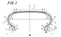
- FIG. 1 is a cross-sectional view in the tire width direction of an embodiment of a pneumatic tire of the present invention.
- the pneumatic tire shown in FIG. 1 has a pair of bead portions 1 and a pair of sidewall portions 2 and a tread portion 3 connected to both sidewall portions 2, and extends in a toroidal shape between the pair of bead portions 1.
- a belt 5 comprising a carcass 4 composed of a single carcass ply that reinforces each of the parts 1, 2, 3 and two belt layers disposed on the outer side in the tire radial direction of the carcass 4 of the tread portion 3.
- the illustrated carcass 4 is composed of a single carcass ply, and has a main body extending in a toroidal shape between a pair of bead cores 7 and around each bead core 7 from the inside to the outside in the tire width direction.
- the number of plies and the structure of the carcass 4 are not limited to this.
- a bead filler 8 is disposed between the carcass main body portion and the carcass folded portion.
- a belt 5 composed of two belt layers is disposed on the outer side in the tire radial direction of the crown portion of the carcass 4. It consists of a rubberized layer of steel cords that extends at an angle to the tire equatorial plane E, and the two belt layers are laminated so that the steel cords constituting the belt layer intersect with each other across the tire equatorial plane E
- the belt 5 is configured.
- the belt 5 in the figure is composed of two belt layers.
- the number of belt layers constituting the belt 5 may be three or more.
- a single belt reinforcing layer 6 having no steel cord is disposed on the outer side in the tire radial direction of the belt 5, but the pneumatic tire of the present invention has a belt reinforcing layer. 6 may not be provided, and the number of belt reinforcing layers 6 may be two or more.
- a short fiber 10 to be described later is fixed to a region including at least a position corresponding to the maximum width position 11 where the sidewall portion of the tire inner peripheral surface has the maximum width MW.
- cavity resonance can be reduced by providing the short fibers to at least a part of the inner peripheral surface of the tire.
- the tire thickness (hereinafter also referred to as “gauge”) at the maximum width position 11 of the sidewall portion is BW ⁇ (1- ⁇ ) in relation to the width BW of the bead core and the flatness ratio AS of the tire.
- AS the flatness ratio AS of the pneumatic tire of the present invention is 0.55 (55%) or less, more preferably 0.35 to 0.55.
- AS the flattening ratio AS is 55% or less, the effect of improving rigidity due to the provision of a short fiber adhering portion described later surely appears.
- the tire inner circumference including at least a portion of the tire inner circumferential surface corresponding to the sidewall portion maximum width position 11 may occur. It is necessary to give a short fiber fixing part to at least a part of the surface area.
- the bead filler height BH of the pneumatic tire of the present invention is preferably 25 mm or less, particularly 15 to 25 mm.
- the bead filler height BH of the pneumatic tire of the present invention is preferably 25 mm or less, particularly 15 to 25 mm.
- the minimum tire thickness in the region (region D in the drawing) from the sidewall portion maximum width position 11 to the outer end in the tire width direction of the belt 5 is 10 mm or less, particularly 6 to 10 mm. It is preferable. By setting the minimum tire thickness in this region to 10 mm or less, it is possible to reliably reduce the weight of the tire before fixing the short fibers as compared with a commercially available tire. However, in this case, the side cut resistance of the tire may be particularly deteriorated. In this case, it is necessary to provide a short fiber fixing portion on at least a part of the tire inner peripheral surface in the region D.
- the number of plies at the maximum width position 11 of the sidewall portion of the pneumatic tire of the present invention is preferably 3 or less. By reducing the number of plies, the tire weight can be reduced.
- short fibers 10 are also fixed to the tire inner peripheral surface of the tread portion 3 among the tire inner peripheral surfaces in order to further enhance the cavity resonance noise reduction effect.
- the fixing of the short fiber to this portion may be omitted.
- short fibers 10 used in the short fiber fixing layer short fibers such as organic synthetic fibers, inorganic fibers, regenerated fibers, and natural fibers can be used.
- organic synthetic fibers include polyolefins such as polyethylene, polypropylene, and polybutylene, aliphatic polyamides such as nylon, aromatic polyamides such as Kevlar, polyesters such as polyethylene terephthalate, polyethylene naphthalate, polyethylene succinate, and polymethyl methacrylate. , Syndiotactic-1,2-polybutadiene, acrylonitrile-butadiene-styrene copolymer, polystyrene, and fibers made of these copolymers.
- inorganic fibers include carbon fibers and glass fibers.
- regenerated fibers include rayon and cupra.
- natural fibers include cotton, silk, wool, and the like.
- the pneumatic tire of the present invention it is preferable that 500 or more short fibers are provided per square centimeter in a region where the short fibers are fixed to the tire inner peripheral surface. In this case, the effect of reducing the cavity resonance sound can be obtained with certainty. In addition, from the viewpoint of obtaining a more excellent cavity resonance noise reduction effect, it is more preferable that 1000 or more short fibers are provided per square centimeter, and 1000 or more and 20000 or less are provided per square centimeter. Particularly preferred.
- the short fibers have an average length of 0.5 to 10 mm.
- the length of the short fiber By setting the length of the short fiber to 0.5 mm or more, an effect of reducing the cavity resonance sound can be sufficiently obtained.
- the average length of the short fibers is particularly preferably 2 to 8 mm.
- the area where the short fibers are fixed is preferably 25% or more, particularly 50% or more, and more preferably 70% or more with respect to the area of the tire inner peripheral surface.
- the short fibers have an average diameter of 1 to 500 ⁇ m. In this case, it is possible to suppress the occurrence of yarn breakage in the short fiber manufacturing process, to suppress a decrease in short fiber productivity, and to suppress an increase in rolling resistance due to an increase in the weight of the tire. The reduction in fuel consumption can be suppressed.
- the ratio (L / D) of the short fiber length (L) to the diameter (D) is in the range of 5 ⁇ L / D ⁇ 2000. If the ratio (L / D) of the short fiber length to the diameter is less than 5, the effect of reducing the cavity resonance noise is reduced. On the other hand, if the ratio (L / D) of the short fiber length to the diameter exceeds 2000, there is a possibility that the short fiber is entangled and the sound absorbing effect cannot be sufficiently exhibited.
- the region where the short fibers are fixed is composed of a plurality of short fiber fixing layers, and the plurality of short fiber fixing layers are fixed independently of each other.
- the short fiber fixing layer is formed on the inner peripheral surface of the tire by the short fibers and the adhesive.
- the adhesive to be used is not particularly limited, and any adhesive can be used, but a urethane resin adhesive, an acrylic resin adhesive, an epoxy resin adhesive, and the like can be suitably used.
- the thickness of the formed adhesive layer is not particularly limited as long as it does not exceed the length of the short fiber, but it is preferably 50 to 500 ⁇ m.
- the short fibers 10 are provided on the tire inner peripheral surface by electrostatic flocking after the coating step, that is, in the bonding step.
- the short fiber 10 can be adhered to the tire inner peripheral surface by various methods, but by using electrostatic flocking, the short fiber 10 can be easily fixed in a standing state on the tire inner peripheral surface.
- a pneumatic tire capable of obtaining a sound absorption effect can be efficiently manufactured.
- Electrostatic flocking is a processing technology that charges short fibers and implants the short fibers vertically onto an object that has been coated with an adhesive by electrostatic force. It is suitable for planting the short fibers 10 on the inner circumferential surface of the tire having a three-dimensional curvature.
- the pneumatic tire of the present invention described above is usually assembled to a rim, and used as an assembly of a tire and a rim attached to a target vehicle.
- the above-described short fibers may be fixed to a part or the entire surface of the rim.
- Examples 1 to 3> As shown in Table 1, a tire having a reduced tire weight was prepared by reducing the sidewall portion maximum width position, the gauge in the region D, and the bead filler height BH from tires of size 255 / 35R20 that are usually commercially available. . Nylon short fibers were fixed to the entire inner peripheral surface of the weight-reducing tire with an adhesive. The number of short fibers in the short fiber fixing region was 2000 per square centimeter, the average length was 4 mm, the average diameter was 50 ⁇ m, and the short fiber fixing area ratio was 100%. As the adhesive, a urethane resin adhesive was used, and the average thickness of the formed adhesive layer was 250 ⁇ m. A test tire of Example 2 was manufactured in the same manner as in Example 1 except that the short fibers were arranged only in the region U. A test tire of Example 3 was manufactured in the same manner as in Example 1 except that the short fibers were arranged only in the region D.
- Comparative Examples 1 and 2 The tire of the size 255 / 35R20 which is usually marketed as shown in Table 1 was used as Comparative Example 1.
- a test tire of Comparative Example 2 was manufactured in the same manner as in Example except that no short fiber was fixed.
- Cavity resonance, steering stability, and side cut resistance were evaluated for the tires of Examples 1 to 3 and Comparative Examples 1 and 2 as follows.
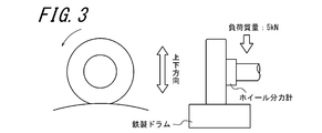
- ⁇ Cavity resonance> Each test tire was mounted on an 8.5J-20 rim, and the surface of an iron plate having a diameter of 1.7 m was applied as shown in FIG. 3 under the conditions of a filling internal pressure of 260 kPa, a tire load mass of 5.0 kPa, and a speed of 80 mph. It was rolled by using a drum testing machine (FIG. 3) equipped with an iron drum, and the vertical tire axial force produced using a wheel force meter was measured and evaluated. The resulting frequency spectrum is shown in FIG. In the spectrum of FIG.
- SA angle / CA angle SA angle: slip angle (angle between the tire equatorial plane and the surface on which the pendulum moves), CA angle: camber angle (angle between the tire surface and a surface perpendicular to the ground)
- Example 1 the peak observed in the vicinity of 210 Hz was significantly reduced by 3 to 5 dB in the tires of Examples 1 to 3 as compared with Comparative Example 1.
- Examples 1 to 3 have steering stability and side cut resistance in Example 1, although the weight is almost the same as that of Comparative Example 2. In both cases, it was found that steering stability was improved in Example 2, and side-cut resistance was improved in Example 3.
- SYMBOLS 1 ... Bead part, 1A ... Tire radial inside end part of bead part, 2 ... Side wall part, 3 ... Tread part, 4 ... Carcass, 5 ... Belt, 6 ... Belt reinforcement layer, 7 ... Bead core, 8 ... Bead filler , 9 ... Inner liner, 10 ... Short fiber, 11 ... Groove part, MW ... Maximum width of sidewall part, BW ... Width of bead core part, BH ... Height of bead filler, E ... Tire equatorial plane, U ... Side wall part A region from the maximum width position to the outer end portion of the bead core in the tire radial direction, D: a region from the sidewall portion maximum width position to the outer end portion in the belt width direction.
Landscapes
- Engineering & Computer Science (AREA)
- Mechanical Engineering (AREA)
- Tires In General (AREA)
Abstract
タイヤの重量を増やすことなく、操縦安定性の低下と耐サイドカット性低下の少なくとも一方を抑え、さらに空洞共鳴音低減を図ることのできる空気入りタイヤを提供する。 偏平率ASが55%以下であり、サイドウォール部最大幅位置に相当するタイヤ内周面の位置を少なくとも一部に包含するタイヤ内周面の領域に短繊維が固着され、前記サイドウォール部最大幅位置のタイヤ厚さが、ビードコアの幅BWと、前記偏平率ASとの関係において、BW×(1-AS)以下である、ことを特徴とする空気入りタイヤ。
Description
本発明は、空気入りタイヤに関する。
空気入りタイヤは、その構造上、タイヤ内部の円管長さに起因する空洞共鳴現象を有することが知られている。そして、いずれの空気入りタイヤにおいても、その周長から空洞共鳴周波数は200~270Hzの範囲となり、不快な車室内騒音の一因となっている。
上記の通り、車室内騒音の発生要因がタイヤ内部の空気の共鳴であることから、その改良手法としては、タイヤ内部で吸音させる方法が有効であり、従来、例えば、特許文献1に記載されているように、タイヤ内周面に短繊維を接着する手法等が提案されている。
ところで、近年、自動車の燃費改善のために、タイヤの重量低減が求められている。タイヤの重量低減のためには、サイド部のゲージ(厚み)、ビードフィラーの高さ、カーカスプライ枚数、カーカスプライ折り返しの高さ等のいずれかを低減させることとなる。
しかしながら、タイヤの重量を低減するために、サイド部のゲージ(厚み)、ビードフィラーの高さ、プライ枚数、プライ折り返しの高さ等を低減すると、タイヤの剛性が低下し、操縦安定性の低下、ピンチカット等のサイドカットに対する強度の低下を招く、という問題があった。
そこで、本発明は、タイヤの重量を大きく増やすことなく、操縦安定性の低下と耐サイドカット性の低下の少なくとも一方を抑え、さらに空洞共鳴音低減を図ることのできる空気入りタイヤを提供することを目的とする。
本発明の空気入りタイヤは、偏平率ASが55%以下であり、サイドウォール部最大幅位置に相当するタイヤ内周面の位置を少なくとも一部に包含するタイヤ内周面の領域に短繊維が固着され、前記サイドウォール部最大幅位置のタイヤ厚さが、ビードコアの幅BWと、前記偏平率ASとの関係において、BW×(1-AS)以下である、ことを特徴とする。
なお、本発明における「幅」及び「幅方向」とは、いずれもタイヤ幅方向の距離又は長さ、及びタイヤの幅方向を指すものとする。また、本発明の空気入りタイヤにおける「偏平率」や各部位の寸法等は、タイヤを適用リムに組み付けて規定内圧を充填した無負荷の状態で測定するものとする。上記の「適用リム」とは、タイヤサイズに応じて下記の規格に規定された標準リム(下記TRAのYEAR BOOKでは、“Design Rim”、下記ETRTOのSTANDARDS MANUALでは“Measuring Rim”)をいい、「規定内圧」とは、下記の規格において、最大負荷能力に対応して規定される空気圧をいい、「最大負荷能力」とは、下記の規格でタイヤに付加されることが許容される最大の質量をいう。そして、その規格とは、タイヤが生産または使用される地域に有効な産業規格によって決められたものであり、例えば、アメリカ合衆国では、“THE TIRE AND RIM ASSOCIATION INC.(TRA)”の“Year Book”であり、欧州では“The European Tire and Rim Technical Organization(ETRO)”であり、日本では、“日本自動車タイヤ協会(JATMA)”の“JATMA YEAR BOOK”である。
なお、本発明における「幅」及び「幅方向」とは、いずれもタイヤ幅方向の距離又は長さ、及びタイヤの幅方向を指すものとする。また、本発明の空気入りタイヤにおける「偏平率」や各部位の寸法等は、タイヤを適用リムに組み付けて規定内圧を充填した無負荷の状態で測定するものとする。上記の「適用リム」とは、タイヤサイズに応じて下記の規格に規定された標準リム(下記TRAのYEAR BOOKでは、“Design Rim”、下記ETRTOのSTANDARDS MANUALでは“Measuring Rim”)をいい、「規定内圧」とは、下記の規格において、最大負荷能力に対応して規定される空気圧をいい、「最大負荷能力」とは、下記の規格でタイヤに付加されることが許容される最大の質量をいう。そして、その規格とは、タイヤが生産または使用される地域に有効な産業規格によって決められたものであり、例えば、アメリカ合衆国では、“THE TIRE AND RIM ASSOCIATION INC.(TRA)”の“Year Book”であり、欧州では“The European Tire and Rim Technical Organization(ETRO)”であり、日本では、“日本自動車タイヤ協会(JATMA)”の“JATMA YEAR BOOK”である。
通常、サイドウォール部最大幅位置の厚さがBW×(1-AS)以下であると、サイド部の剛性が低いため、操縦安定性、耐サイドカット性の面で性能的に不十分である。本発明においては、この部分に短繊維を固着させ、固着に使用する接着剤により形成される接着剤層により剛性を高めることができ、結果として操縦安定性の低下、耐サイドカット性低下を防ぐことが可能となる。加えて、タイヤをリムに装着したときに形成される空気室内面に対してこれらの短繊維が設けられ、吸音効果を発揮し、空洞共鳴音の発生を抑制できる。上記効果は、偏平率が55%以下の空気入りタイヤにおいて、確実に実現し得るものである。
本発明の空気入りタイヤの一実施態様においては、前記サイドウォール部最大幅位置に相当する位置からビードコアのタイヤ半径方向外側端までのタイヤ内周面の領域の少なくとも一部に前記短繊維が固着され、ビードフィラーの高さが25mm以下である。
なお、本発明における「高さ」とは、タイヤ半径方向の距離又は長さを指すものとする。
ビードフィラー高さを25mm以下とすることで、タイヤの軽量化に寄与することが可能である。しかし、これに伴って、操縦安定性、耐サイドカット性の低下が生じ得るため、この場合、サイドウォール部の最大幅位置からビード側の領域に短繊維を固着させて、剛性を高めることが望ましい。サイドウォール部の最大幅位置からビード側の領域は、特に操縦安定性への寄与が大きいため、これらの部分の剛性を高めることが望まれる。
なお、本発明における「高さ」とは、タイヤ半径方向の距離又は長さを指すものとする。
ビードフィラー高さを25mm以下とすることで、タイヤの軽量化に寄与することが可能である。しかし、これに伴って、操縦安定性、耐サイドカット性の低下が生じ得るため、この場合、サイドウォール部の最大幅位置からビード側の領域に短繊維を固着させて、剛性を高めることが望ましい。サイドウォール部の最大幅位置からビード側の領域は、特に操縦安定性への寄与が大きいため、これらの部分の剛性を高めることが望まれる。
本発明の空気入りタイヤの他の実施態様は、一枚以上のベルト層からなるベルトをトレッド部に具え、前記サイドウォール部最大幅位置からベルトのタイヤ幅方向外側端までのタイヤ内周面の領域の少なくとも一部に前記短繊維が固着され、前記領域における最小のタイヤ厚さが10mm以下である。
ここで、「タイヤ厚さ」とは、タイヤを適用リムに組み付けて規定内圧を充填した無負荷の状態のタイヤ幅方向断面で、対象となるタイヤ内周面の位置または領域における、タイヤ内周面に対して垂直に測定したタイヤ厚さを指すものとする。
前記最大幅位置からベルトの幅方向外側端部までの領域の最小のタイヤ厚さを10mm以下とすることで、タイヤの軽量化に寄与することが可能である。しかし、これに伴う耐サイドカット性、操縦安定性の低下を生じ得るため、この場合、前記最大幅位置からベルトの幅方向外側端までの領域に短繊維を固着させて、剛性を高めることが望ましい。サイドウォール部の最大幅位置からベルトの幅方向外側端部までの領域は、特に耐サイドカット性への寄与が大きいため、これらの部分の剛性を高めることが望まれる。
本発明によれば、タイヤの重量を増やすことなく、操縦安定性の低下、耐サイドカット性の低下を抑え、さらに空洞共鳴音低減を図ることのできる空気入りタイヤを提供することができる。
発明者は、タイヤ内の空洞共鳴を抑制するためにタイヤ内周面に短繊維を固着させたタイヤにおいて、特に短繊維を固着させる接着剤層が存在するために、タイヤの短繊維固着部の剛性が高くなることに着目し、特に偏平率が55%以下の空気入りタイヤについて、タイヤの重量低減のためにサイド部のゲージ(厚み)、ビードフィラーの高さ、カーカスプライ枚数、カーカスプライ折り返しの高さ等のいずれかを減じたタイヤにおいて生じる剛性の低下、並びにこれにより生じ得る操縦安定性及び耐サイドカット性の低下を、該固着部を配することで軽減し得ることを見出し、本発明に至った。
以下に、図を参照しながら本発明を詳細に例示説明する。図1は、本発明の空気入りタイヤの一実施形態のタイヤ幅方向の断面図である。図1に示す空気入りタイヤは、一対のビード部1及び一対のサイドウォール部2と、両サイドウォール部2に連なるトレッド部3とを有し、上記一対のビード部1間にトロイド状に延在してこれら各部1,2,3を補強する一枚のカーカスプライからなるカーカス4と、前記トレッド部3の前記カーカス4のタイヤ半径方向外側に配置された二枚のベルト層からなるベルト5と、該ベルト5のタイヤ半径方向外側に配置された一層のベルト補強層6と、前記ビード部1内に夫々埋設したビードコア7のタイヤ半径方向外側に配置されたビードフィラー8と、上記カーカス4のタイヤ内周面側に配置したインナーライナー9とを備える。
なお、図1及び図2は、タイヤを適用リムに組み付けて規定内圧を充填した無負荷の状態を示すものとする。
なお、図1及び図2は、タイヤを適用リムに組み付けて規定内圧を充填した無負荷の状態を示すものとする。
図示例のカーカス4は、一枚のカーカスプライから構成され、また、一対のビードコア7間にトロイド状に延在する本体部と、各ビードコア7の周りで、タイヤ幅方向の内側から外側に向けてタイヤ半径方向外方に巻上げた折り返し部とからなるが、本発明の空気入りタイヤにおいて、カーカス4のプライ数及び構造は、これに限られるものではない。また、図示例の空気入りタイヤにおいては、カーカス本体部とカーカス折り返し部との間にビードフィラー8が配置されている。
また、図示例の空気入りタイヤのトレッド部3においては、上記カーカス4のクラウン部のタイヤ半径方向外側には二枚のベルト層からなるベルト5が配置されており、該ベルト層は、通常、タイヤ赤道面Eに対して傾斜して延びるスチールコードのゴム引き層からなり、二枚のベルト層は、該ベルト層を構成するスチールコードが互いにタイヤ赤道面Eを挟んで交差するように積層されてベルト5を構成する。図中のベルト5は、二枚のベルト層からなるが、本発明の空気入りタイヤにおいては、ベルト5を構成するベルト層の枚数は、三枚以上であってもよい。また、図示例の空気入りタイヤにおいては、スチールコードを有しない、一層のベルト補強層6が、ベルト5のタイヤ半径方向外側に配置されているが、本発明の空気入りタイヤは、ベルト補強層6を備えていなくてもよく、また、ベルト補強層6の枚数は、二枚以上であってもよい。
本発明の空気入りタイヤは、タイヤ内周面のサイドウォール部が最大幅MWとなる最大幅位置11に相当する位置を少なくとも一部に包含する領域に、後述の短繊維10が固着される。このようにタイヤ内周面の少なくとも一部に短繊維が付与されることにより、空洞共鳴を軽減することができる。
本発明の空気入りタイヤにおけるサイドウォール部の最大幅位置11のタイヤ厚さ(以下「ゲージ」ともいう)は、ビードコアの幅BWと、タイヤの偏平率ASとの関係で、BW×(1-AS)以下である。ここで、本発明の空気入りタイヤの偏平率ASは0.55(55%)以下、より好適には0.35~0.55とする。偏平率ASが55%以下であると、後述の短繊維固着部の付与による剛性向上効果が確実に現れるものである。サイドウォール部のゲージを上記式に適合する薄さとすることで、短繊維固着前におけるタイヤの重量を十分に軽くすることができる。しかし、このままではタイヤの剛性低下による操縦安定性及び耐サイドカット性の低下を生じ得るため、サイドウォール部最大幅位置11に相当するタイヤ内周面の位置を少なくとも一部に包含するタイヤ内周面の領域の少なくとも一部に短繊維固着部を付与する必要がある。
本発明の空気入りタイヤのビードフィラー高さBHは、25mm以下、特に15~25mmであることが好ましい。ビードフィラーの高さを25mm以下とすることで、短繊維固着前におけるタイヤの重量を、一般に市販されるタイヤと比して確実に減じることができる。しかし、このままではタイヤのビード付近の剛性が低くなり、特に操縦安定性が低下するおそれがあるため、この場合、サイドウォール部最大幅位置11に相当するタイヤ内周面の位置からビードコアのタイヤ半径方向外側端までのタイヤ内周面の領域(図中の領域U)の少なくとも一部に短繊維固着部を付与することが好ましい。
本発明の空気入りタイヤは、サイドウォール部最大幅位置11からベルト5のタイヤ幅方向外側端までの領域(図中の領域D)の最小のタイヤ厚さが10mm以下、特に6~10mmであることが好ましい。この領域の最小のタイヤ厚さを10mm以下とすることで、短繊維固着前におけるタイヤの重量を、一般に市販されるタイヤと比して確実に減じることができる。しかし、このままでは、特にタイヤの耐サイドカット性の低下を生じ得るため、この場合、当該領域Dのタイヤ内周面の少なくとも一部に短繊維固着部を付与する必要がある。
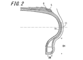
図2に示されるように、本発明の空気入りタイヤのサイドウォール部の最大幅位置11でのプライ枚数は、3枚以下であることが好ましい。プライ枚数を減じることで、タイヤ重量を減じることができる。
図示例の空気入りタイヤでは、より空洞共鳴音低減効果を高めるために前記タイヤ内周面のうち、トレッド部3のタイヤ内周面にも短繊維10が固着されているが、重量の増加を抑えたい場合には、この部分への短繊維の固着を省略してもよい。
ここで、短繊維固着層に使用される上記短繊維10としては、有機合成繊維、無機繊維、再生繊維、天然繊維等の短繊維を用いることができる。また、有機合成繊維としては、例えば、ポリエチレン、ポリプロピレン、ポリブチレン等のポリオレフィン、ナイロン等の脂肪族ポリアミド、ケブラー等の芳香族ポリアミド、ポリエチレンテレフタレート、ポリエチレンナフタレート、ポリエチレンサクシネート、ポリメチルメタクリレート等のポリエステル、シンジオタクチック-1,2-ポリブタジエン、アクリロニトリル-ブタジエン-スチレン共重合体、ポリスチレン、及びこれらの共重合体等からなる繊維が挙げられる。また、無機繊維としては、例えば、カーボン繊維、グラスファイバー等が挙げられる。また、再生繊維としては、例えば、レーヨン、キュプラ等が挙げられる。また、天然繊維としては、例えば、綿、絹、羊毛等が挙げられる。
本発明の空気入りタイヤにおいては、前記短繊維がタイヤ内周面に固着されている領域において、前記短繊維が1平方センチメートル当たり500本以上設けられていることが好ましい。この場合、空洞共鳴音の低減効果を確実に得ることができる。なお、より優れた空洞共鳴音低減効果を得る観点から、前記短繊維は、1平方センチメートル当たり1000本以上設けられていることが更に好ましく、1平方センチメートル当たり1000本以上20000本以下設けられていることが特に好ましい。
本発明の空気入りタイヤの他の好適例において、前記短繊維は、平均長さが0.5~10mmである。短繊維の長さを0.5mm以上とすることで、空洞共鳴音を低減する効果が十分に得られる。一方で、短繊維の平均長さを10mm以下とすることで、短繊維同士の絡み合いによるダマが発生し、吸音効果が十分に発現できなくなる問題を回避することができる。なお、同様の観点から、前記短繊維の平均長さは、2~8mmが特に好ましい。
短繊維が固着されている面積は、タイヤ内周面の面積に対して、25%以上、特に50%以上、さらに70%以上とすることが好ましい。短繊維固着面積率を50%以上とすることで、空洞共鳴音を確実に低減することができる。
短繊維が固着されている面積は、タイヤ内周面の面積に対して、25%以上、特に50%以上、さらに70%以上とすることが好ましい。短繊維固着面積率を50%以上とすることで、空洞共鳴音を確実に低減することができる。
また、本発明の空気入りタイヤの他の好適例において、前記短繊維は、平均直径が1~500μmである。この場合、短繊維の製造工程における糸切れの発生を抑制して、短繊維の生産性の低下を抑制でき、また、タイヤの重量増による転がり抵抗の上昇を抑制して、タイヤを装着した車両の燃費の低下を抑制することができる。
また、本発明の空気入りタイヤにおいては、前記短繊維の長さ(L)と直径(D)との比(L/D)が5≦L/D≦2000の範囲にあることが好ましい。短繊維の長さと直径の比(L/D)が5未満では、空洞共鳴音を低減する効果が小さくなる。一方、短繊維の長さと直径の比(L/D)が2000を超えると、短繊維同士の絡み合いによるダマが発生し、吸音効果が十分に発現できなくなるおそれがある。
また、本発明の空気入りタイヤにおいては、前記短繊維の固着されている領域が複数の短繊維固着層からなり、該複数の短繊維固着層が互いに独立して固着されていることが好ましい。短繊維の固着されている領域を、連続せずに設けることにより、仮に接着層がはがれることがあったとしても、はがれる範囲が極僅かで止まり、空洞共鳴抑制効果を維持することができる。
本発明の空気入りタイヤを製造するには、まず、サイドウォール部が最大幅MWとなる最大幅位置11に相当する位置を少なくとも一部に包含する領域に接着剤を塗布する塗布工程と、前記接着剤を塗布した部位に短繊維を接着させる接着工程とを備える。短繊維と接着剤により、タイヤ内周面に短繊維固着層を形成することを特徴とする。この製造方法によれば、空洞共鳴音の発生を抑制できる空気入りタイヤを効率的に製造することができる。
使用する接着剤は特に限定されず、任意の接着剤を使用することができるが、ウレタン樹脂系接着剤、アクリル樹脂系接着剤、エポキシ樹脂系接着剤などを好適に使用できる。形成される接着剤層の厚みも短繊維の長さを超えなければ、特に限定されるものではないが、50~500μmであることが好ましい。
本発明の空気入りタイヤの製造方法においては、塗布工程の後、すなわち接着工程において、静電植毛加工により前記短繊維10をタイヤ内周面に設けることが好ましい。短繊維10は、種々の方法でタイヤ内周面に接着させることができるが、静電植毛加工を用いることにより、短繊維10を簡単にタイヤ内周面に立設させた状態で固着させることができ、吸音効果を得ることのできる空気入りタイヤを効率的に製造することができる。
静電植毛加工は、短繊維を帯電させ、静電気力により、予め接着剤を塗布した物体に短繊維を垂直に植毛する加工技術であるため、複雑な形状の物体表面にも均一に短繊維を植毛することができ、3次元的に曲率をもったタイヤ内周面に短繊維10を植毛するのに適している。
上述した本発明の空気入りタイヤは、通常、リムに組み付けられ、タイヤとリムとの組立体として、目的の車両に取り付けられて使用される。ここで、空洞共鳴音低減効果を更に高めるために、リムの一部又は全面に上述した短繊維を固着してもよい。
以下に、実施例を挙げて本発明を更に詳しく説明するが、本発明は下記の実施例に何ら限定されるものではない。
<実施例1~3>
表1に示すような、通常市販されるサイズ255/35R20のタイヤから、サイドウォール部最大幅位置及び上記領域Dのゲージ並びにビードフィラー高さBHを減じて、タイヤ重量を低減したタイヤを調製した。重量低減タイヤの内周面の全体に、ナイロン製の短繊維を接着剤で固着した。短繊維固着領域における短繊維は、一平方センチメートル当たりの本数を2000本、平均長さを4mm、平均直径を50μm、短繊維固着面積率を100%とした。接着剤としてはウレタン樹脂系接着剤を使用し、形成された接着剤層の平均膜厚は250μmであった。
短繊維を上記領域Uにのみ配した以外は実施例1と同様にして、実施例2の供試タイヤを製造した。
短繊維を上記領域Dにのみ配した以外は実施例1と同様にして、実施例3の供試タイヤを製造した。
<比較例1、2>
表1に示すような、通常市販されるサイズ255/35R20のタイヤを比較例1とした。短繊維を全く固着させない以外は、実施例と同様にして比較例2の供試タイヤを製造した。
表1に示すような、通常市販されるサイズ255/35R20のタイヤを比較例1とした。短繊維を全く固着させない以外は、実施例と同様にして比較例2の供試タイヤを製造した。
実施例1~3及び比較例1、2の各タイヤに対して、以下のようにして、空洞共鳴、操縦安定性、及び耐サイドカット性を評価した。
<空洞共鳴>
各供試タイヤを8.5J-20のリムに装着して、充填内圧260kPa、タイヤ負荷質量5.0kN、時速80km/hの条件で、図3に示すように直径1.7mの鉄板表面を持つ鉄製ドラムを備えたドラム試験機(図3)を用いて転動させ、ホイール分力計を用いて生じる上下方向タイヤ軸力を測定して評価した。その結果の周波数スペクトルを図4に示す。図4のスペクトルにおいて、210Hzのピークが低いほど、タイヤの空洞共鳴音が低減したことを示す。図4のスペクトルから。各供試タイヤの比較例1のタイヤに対する当該ピークの低減量(dB)を求めた。
<操縦安定性>
車両の操縦安定性を支配するタイヤのコーナリング特性の指標として、フラットベルト試験機で測定したCP(コーナリングパワー)を評価した。各供試タイヤを8.5J-20のリムに装着して、タイヤの充填内圧260kPa、負荷質量を5.0kNとし、時速80km/hでフラットベルト試験機を用いてタイヤを転動させ、±0度、0.5度、1度のスリップ角を付与してタイヤに発生した応力を測定し、0度における傾き(kgf/deg)を求めた。CPが1.5kN/deg以上であれば、十分な操縦安定性を有しているといえる。
<耐サイドカット性>
各供試タイヤを8.5J-20のリムに装着して、内圧が260MPaとなるよう充填し、図5に示す、ストライカー形状R(打撃面の半径)=50mm、振り子長さL=1830mm(6ft)、振り子重量M=60.55kgの振り子型の試験機を用いて、振り上げ角θを90度として供試タイヤに衝突させた。その際、SA角/CA角(SA角:スリップ角(タイヤ赤道面と振り子の移動する面との角度)、CA角:キャンバー角(タイヤ面が地面に垂直な面となす角度))を、0度/5度とした。各供試タイヤの破損の有無を観察した。

図4において、210Hz付近に見られるピークが、実施例1~3のタイヤでは、比較例1と比較して3~5dBの大きな低減効果が得られた。また、比較例2の重量低減タイヤと比較して、実施例1~3は、その重量は比較例2とほぼ変わらないにも関わらず、実施例1においては操縦安定性と耐サイドカット性の両方、実施例2においては操縦安定性、実施例3においては耐サイドカット性が改善していることが分かった。
1…ビード部、1A…ビード部のタイヤ半径方向内側端部、2…サイドウォール部、3…トレッド部、4…カーカス、5…ベルト、6…ベルト補強層、7…ビードコア、8…ビードフィラー、9…インナーライナー、10…短繊維、11…溝部分、MW…サイドウォール部の最大幅、BW…ビードコア部の幅、BH…ビードフィラー高さ、E…タイヤ赤道面、U…サイドウォール部最大幅位置からビードコアのタイヤ半径方向外側端部までの領域、D…サイドウォール部最大幅位置からベルトの幅方向外側端部までの領域。
Claims (3)
- 偏平率ASが55%以下であり、サイドウォール部最大幅位置に相当するタイヤ内周面の位置を少なくとも一部に包含するタイヤ内周面の領域に短繊維が固着され、前記サイドウォール部最大幅位置のタイヤ厚さが、ビードコアの幅BWと、前記偏平率ASとの関係において、BW×(1-AS)以下である、ことを特徴とする空気入りタイヤ。
- 前記サイドウォール部最大幅位置に相当するタイヤ内周面の位置からビードコアのタイヤ半径方向外側端までのタイヤ内周面の領域の少なくとも一部に前記短繊維が固着され、ビードフィラーの高さが25mm以下である、請求項1に記載の空気入りタイヤ。
- 一枚以上のベルト層からなるベルトをトレッド部に具え、前記サイドウォール部最大幅位置からベルトのタイヤ幅方向外側端までの領域の少なくとも一部に前記短繊維が固着され、前記領域における最小のタイヤ厚さが10mm以下である、請求項1に記載の空気入りタイヤ。
Priority Applications (3)
| Application Number | Priority Date | Filing Date | Title |
|---|---|---|---|
| EP14754769.9A EP2960076B1 (en) | 2013-02-20 | 2014-02-04 | Pneumatic tire |
| CN201480008979.5A CN105008144B (zh) | 2013-02-20 | 2014-02-04 | 充气轮胎 |
| US14/761,117 US20150360515A1 (en) | 2013-02-20 | 2014-02-04 | Pneumatic tire |
Applications Claiming Priority (2)
| Application Number | Priority Date | Filing Date | Title |
|---|---|---|---|
| JP2013-030808 | 2013-02-20 | ||
| JP2013030808A JP5519814B1 (ja) | 2013-02-20 | 2013-02-20 | 空気入りタイヤ |
Publications (1)
| Publication Number | Publication Date |
|---|---|
| WO2014129131A1 true WO2014129131A1 (ja) | 2014-08-28 |
Family
ID=51031306
Family Applications (1)
| Application Number | Title | Priority Date | Filing Date |
|---|---|---|---|
| PCT/JP2014/000581 WO2014129131A1 (ja) | 2013-02-20 | 2014-02-04 | 空気入りタイヤ |
Country Status (5)
| Country | Link |
|---|---|
| US (1) | US20150360515A1 (ja) |
| EP (1) | EP2960076B1 (ja) |
| JP (1) | JP5519814B1 (ja) |
| CN (1) | CN105008144B (ja) |
| WO (1) | WO2014129131A1 (ja) |
Cited By (2)
| Publication number | Priority date | Publication date | Assignee | Title |
|---|---|---|---|---|
| WO2020121573A1 (ja) * | 2018-12-13 | 2020-06-18 | 株式会社ブリヂストン | 乗用車用空気入りラジアルタイヤ |
| JP2022107743A (ja) * | 2018-12-13 | 2022-07-22 | 株式会社ブリヂストン | 乗用車用空気入りラジアルタイヤ |
Families Citing this family (3)
| Publication number | Priority date | Publication date | Assignee | Title |
|---|---|---|---|---|
| JP5571206B1 (ja) * | 2013-02-05 | 2014-08-13 | 株式会社ブリヂストン | 電磁式発電機の装着方法及び電磁式発電機内蔵タイヤ |
| JP7132172B2 (ja) * | 2019-05-07 | 2022-09-06 | 株式会社ブリヂストン | 空気入りタイヤ |
| JP2021142857A (ja) * | 2020-03-11 | 2021-09-24 | 住友ゴム工業株式会社 | 空気入りタイヤ |
Citations (5)
| Publication number | Priority date | Publication date | Assignee | Title |
|---|---|---|---|---|
| JPH0853003A (ja) * | 1994-06-10 | 1996-02-27 | Sumitomo Rubber Ind Ltd | 空気入りラジアルタイヤの製造方法 |
| US20030051789A1 (en) * | 1999-04-02 | 2003-03-20 | Sumitomo Rubber Industries, Ltd. | Pneumatic tire |
| JP2004082387A (ja) | 2002-08-23 | 2004-03-18 | Bridgestone Corp | 空気入りタイヤの製造方法、空気入りタイヤ、及びタイヤ・リム組立体 |
| JP2007083914A (ja) * | 2005-09-22 | 2007-04-05 | Yokohama Rubber Co Ltd:The | 空気入りタイヤ及びその装着方法 |
| JP2011073511A (ja) * | 2009-09-29 | 2011-04-14 | Yokohama Rubber Co Ltd:The | 空気入りタイヤ |
Family Cites Families (10)
| Publication number | Priority date | Publication date | Assignee | Title |
|---|---|---|---|---|
| JPH0415111A (ja) * | 1990-05-07 | 1992-01-20 | Sumitomo Rubber Ind Ltd | 安全タイヤ |
| US6309494B1 (en) * | 1998-12-04 | 2001-10-30 | Bridgestone/Firestone Research, Inc. | Method of attaching sensitive electronic equipment to the inner surface of a tire |
| JP2001187502A (ja) * | 1999-12-28 | 2001-07-10 | Sumitomo Rubber Ind Ltd | リム及びそれを用いたタイヤとリムの組立体 |
| US6904829B2 (en) * | 2002-09-17 | 2005-06-14 | Anthony Krallman | Deadblow hammer |
| US7404424B2 (en) * | 2003-07-17 | 2008-07-29 | The Yokohama Rubber Co., Ltd. | Pneumatic tire with buffer rubber layer |
| JP4448336B2 (ja) * | 2004-01-09 | 2010-04-07 | 住友ゴム工業株式会社 | 乗用車用ラジアルタイヤ |
| US7890921B2 (en) * | 2006-07-31 | 2011-02-15 | Lifecylce Technologies, Inc. | Automated method for coherent project management |
| JP4089787B1 (ja) * | 2006-11-24 | 2008-05-28 | 横浜ゴム株式会社 | 空気入りラジアルタイヤ |
| CN101784082A (zh) * | 2009-12-22 | 2010-07-21 | 中兴通讯股份有限公司 | 无线局域网内增强服务质量的方法及装置 |
| JP2012250635A (ja) * | 2011-06-03 | 2012-12-20 | Bridgestone Corp | 空気入りタイヤおよびその製造方法 |
-
2013
- 2013-02-20 JP JP2013030808A patent/JP5519814B1/ja active Active
-
2014
- 2014-02-04 CN CN201480008979.5A patent/CN105008144B/zh active Active
- 2014-02-04 WO PCT/JP2014/000581 patent/WO2014129131A1/ja active Application Filing
- 2014-02-04 EP EP14754769.9A patent/EP2960076B1/en active Active
- 2014-02-04 US US14/761,117 patent/US20150360515A1/en not_active Abandoned
Patent Citations (5)
| Publication number | Priority date | Publication date | Assignee | Title |
|---|---|---|---|---|
| JPH0853003A (ja) * | 1994-06-10 | 1996-02-27 | Sumitomo Rubber Ind Ltd | 空気入りラジアルタイヤの製造方法 |
| US20030051789A1 (en) * | 1999-04-02 | 2003-03-20 | Sumitomo Rubber Industries, Ltd. | Pneumatic tire |
| JP2004082387A (ja) | 2002-08-23 | 2004-03-18 | Bridgestone Corp | 空気入りタイヤの製造方法、空気入りタイヤ、及びタイヤ・リム組立体 |
| JP2007083914A (ja) * | 2005-09-22 | 2007-04-05 | Yokohama Rubber Co Ltd:The | 空気入りタイヤ及びその装着方法 |
| JP2011073511A (ja) * | 2009-09-29 | 2011-04-14 | Yokohama Rubber Co Ltd:The | 空気入りタイヤ |
Cited By (5)
| Publication number | Priority date | Publication date | Assignee | Title |
|---|---|---|---|---|
| WO2020121573A1 (ja) * | 2018-12-13 | 2020-06-18 | 株式会社ブリヂストン | 乗用車用空気入りラジアルタイヤ |
| JP2020093681A (ja) * | 2018-12-13 | 2020-06-18 | 株式会社ブリヂストン | 乗用車用空気入りラジアルタイヤ |
| JP7083741B2 (ja) | 2018-12-13 | 2022-06-13 | 株式会社ブリヂストン | 乗用車用空気入りラジアルタイヤ |
| JP2022107743A (ja) * | 2018-12-13 | 2022-07-22 | 株式会社ブリヂストン | 乗用車用空気入りラジアルタイヤ |
| JP7329106B2 (ja) | 2018-12-13 | 2023-08-17 | 株式会社ブリヂストン | 乗用車用空気入りラジアルタイヤ |
Also Published As
| Publication number | Publication date |
|---|---|
| CN105008144A (zh) | 2015-10-28 |
| JP2014159229A (ja) | 2014-09-04 |
| EP2960076B1 (en) | 2018-05-30 |
| EP2960076A4 (en) | 2016-11-02 |
| CN105008144B (zh) | 2017-03-08 |
| JP5519814B1 (ja) | 2014-06-11 |
| EP2960076A1 (en) | 2015-12-30 |
| US20150360515A1 (en) | 2015-12-17 |
Similar Documents
| Publication | Publication Date | Title |
|---|---|---|
| WO2013031165A1 (ja) | 空気入りタイヤ及びその製造方法 | |
| WO2014129131A1 (ja) | 空気入りタイヤ | |
| JP2012086600A (ja) | 空気入りタイヤ | |
| JP5750156B2 (ja) | 空気入りタイヤ | |
| EP2821259A1 (en) | Pneumatic tire | |
| JP2013035428A (ja) | 空気入りタイヤ | |
| JP5478746B1 (ja) | 空気入りタイヤ及びその製造方法 | |
| JP2013035348A (ja) | 空気入りタイヤ | |
| JP5478745B1 (ja) | 空気入りタイヤ及びその製造方法 | |
| JP2013169825A (ja) | 空気入りタイヤ | |
| JP2014159225A (ja) | 空気入りタイヤ及びその製造方法 | |
| JP5054955B2 (ja) | 航空機ラジアルタイヤ | |
| JP2012254742A (ja) | 空気入りタイヤ及びその製造方法 | |
| WO2014097557A1 (ja) | 空気入りタイヤおよび空気入りタイヤの製造方法 | |
| JP6060031B2 (ja) | 空気入りタイヤ | |
| WO2019102873A1 (ja) | 空気入りタイヤ | |
| US8967214B2 (en) | Pneumatic radial tire | |
| JP5891025B2 (ja) | ビードコアおよび空気入りタイヤ | |
| JP2014159226A (ja) | 空気入りタイヤ及びその製造方法 | |
| JP2013095354A (ja) | 空気入りタイヤ | |
| JP2014159227A (ja) | 空気入りタイヤ及びその製造方法 | |
| JP2013184533A (ja) | 空気入りタイヤ |
Legal Events
| Date | Code | Title | Description |
|---|---|---|---|
| 121 | Ep: the epo has been informed by wipo that ep was designated in this application |
Ref document number: 14754769 Country of ref document: EP Kind code of ref document: A1 |
|
| WWE | Wipo information: entry into national phase |
Ref document number: 14761117 Country of ref document: US |
|
| WWE | Wipo information: entry into national phase |
Ref document number: 2014754769 Country of ref document: EP |
|
| NENP | Non-entry into the national phase |
Ref country code: DE |