WO2020121573A1 - 乗用車用空気入りラジアルタイヤ - Google Patents
乗用車用空気入りラジアルタイヤ Download PDFInfo
- Publication number
- WO2020121573A1 WO2020121573A1 PCT/JP2019/027048 JP2019027048W WO2020121573A1 WO 2020121573 A1 WO2020121573 A1 WO 2020121573A1 JP 2019027048 W JP2019027048 W JP 2019027048W WO 2020121573 A1 WO2020121573 A1 WO 2020121573A1
- Authority
- WO
- WIPO (PCT)
- Prior art keywords
- tire
- width direction
- noise
- width
- pneumatic radial
- Prior art date
Links
Images

Classifications
-
- B—PERFORMING OPERATIONS; TRANSPORTING
- B60—VEHICLES IN GENERAL
- B60C—VEHICLE TYRES; TYRE INFLATION; TYRE CHANGING; CONNECTING VALVES TO INFLATABLE ELASTIC BODIES IN GENERAL; DEVICES OR ARRANGEMENTS RELATED TO TYRES
- B60C3/00—Tyres characterised by the transverse section
- B60C3/04—Tyres characterised by the transverse section characterised by the relative dimensions of the section, e.g. low profile
-
- B—PERFORMING OPERATIONS; TRANSPORTING
- B60—VEHICLES IN GENERAL
- B60C—VEHICLE TYRES; TYRE INFLATION; TYRE CHANGING; CONNECTING VALVES TO INFLATABLE ELASTIC BODIES IN GENERAL; DEVICES OR ARRANGEMENTS RELATED TO TYRES
- B60C5/00—Inflatable pneumatic tyres or inner tubes
Definitions
- the present invention relates to a pneumatic radial tire for passenger cars.
- Patent Document 1 The applicant has proposed various narrow and large-diameter pneumatic radial tires for passenger cars in which the tire cross-section width SW and the tire outer diameter OD have a predetermined relationship (for example, Patent Document 1).
- the noise damper when the above-mentioned noise damper is provided on the inner surface of the tire in order to improve the noise damping property, heat is accumulated in the noise damper, and the noise damper and the inner surface of the tire are bonded to each other, for example, after running for a long time. In some cases, the durability of the tire is deteriorated by melting the adhesive layer, peeling the noise suppressor from the inner surface of the tire, or easily causing a failure in the tire member. As described above, it is usually difficult to achieve both the noise control property and the tire durability.
- an object of the present invention is to provide a pneumatic radial tire for passenger cars, which has both noise control and tire durability.
- the pneumatic radial tire for passenger cars of the present invention is A pneumatic radial tire for a passenger vehicle, which comprises a carcass consisting of a ply of a radial arrangement cord, straddling toroidally between a pair of bead portions,
- the sectional width SW of the tire is less than 165 (mm), the ratio SW/OD of the sectional width SW of the tire and the outer diameter OD is 0.26 or less,
- the inner surface of the tire is provided with one or more noise dampers, In the tire width direction cross section when the tire was assembled in a rim, filled with a specified internal pressure, and in an unloaded state, the midpoint of the tire width direction in the tire width direction region from the tire equatorial plane to the ground contact end was set to 1 /4 points,
- the noise suppressor is not provided on the inner surface of the tire in a region outside the 1 ⁇ 4 point in one half portion in the tire width direction with the tire equatorial plane as
- the "rim” is an industrial standard that is effective in regions where tires are produced and used.
- JATMA Joint Automobile Tire Association
- ETRTO European Tire and Rim
- STANDARDS MANUAL of ETRTO, or STANDARDS MANUAL of standard size described in YEAR BOOK of TRA (The Tire and Rim Association, Inc.) in the United States, STANDARDS MANUAL of ETRA , TRA's YEAR BOOK Design Rim) i.e., the above-mentioned "rim” includes, in addition to the current size, a size that may be included in the industry standard in the future.
- the width corresponding to the bead width of the tire Refers to the rim.
- the "specified internal pressure” refers to the air pressure (maximum air pressure) corresponding to the maximum load capacity of a single wheel in the applicable size and ply rating described in JATMA, etc.
- the “specified internal pressure” means the air pressure (maximum air pressure) corresponding to the maximum load capacity specified for each vehicle in which the tire is mounted.
- the “maximum load capacity” described later means a load corresponding to the maximum load capacity.
- the “ground contact end” means both ends in the tire width direction of the ground contact surface which is in contact with the road surface when the tire is incorporated into a rim, a specified internal pressure is filled, and a maximum load is applied.
- the dimensions and the like mean the dimensions and the like in a state in which the tire is incorporated in a rim, a specified internal pressure is filled, and no load is applied.
- the pneumatic radial tire for passenger cars of the present invention is A pneumatic radial tire for a passenger vehicle, which comprises a carcass consisting of a ply of a radial arrangement cord, straddling toroidally between a pair of bead portions,
- the sectional width SW of the tire is 165 (mm) or more, and the sectional width SW (mm) and the outer diameter OD (mm) of the tire are expressed by a relational expression, OD (mm) ⁇ 2.135 ⁇ SW (mm)+282.3
- the inner surface of the tire is provided with one or more noise dampers, In the tire width direction cross section when the tire was assembled in a rim, filled with a specified internal pressure, and in an unloaded state, the midpoint of the tire width direction in the tire width direction region from the tire equatorial plane to the ground contact end was set to 1 /4 points,
- the noise suppressor is not provided on the inner surface of the tire in a region outside the 1 ⁇ 4 point in one half portion
- the pneumatic radial tire for passenger cars of the present invention is A pneumatic radial tire for a passenger vehicle, which comprises a carcass consisting of a ply of a radial arrangement cord, straddling toroidally between a pair of bead portions,
- the sectional width SW (mm) and outer diameter OD (mm) of the tire are expressed by a relational expression, OD (mm) ⁇ -0.0187 x SW (mm) 2 +9.15 x SW (mm)-380
- the inner surface of the tire is provided with one or more noise dampers, In the tire width direction cross section when the tire was assembled in a rim, filled with a specified internal pressure, and in an unloaded state, the midpoint of the tire width direction in the tire width direction region from the tire equatorial plane to the ground contact end was set to 1 /4 points,
- the noise suppressor is not provided on the inner surface of the tire in a region outside the 1 ⁇ 4 point in one half portion in the tire width direction with the
- the “bead portion” refers to a portion in the tire radial direction region from the rim baseline to the tire radial outermost end of the bead filler in the case of having a bead filler, and in the case of not having a bead filler. , The portion in the tire radial direction region from the rim baseline to the tire radial outermost end of the bead core.
- FIG. 3 is a cross-sectional view in the tire width direction showing a pneumatic radial tire for passenger cars according to an embodiment of the first to third aspects of the present invention.
- FIG. 4 is a sectional view in the tire width direction showing a pneumatic radial tire for passenger cars according to another embodiment of the first to third aspects of the present invention.
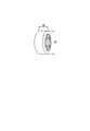
- FIG. 1 is a schematic diagram showing a sectional width SW and an outer diameter OD of a tire.
- a pneumatic radial tire for passenger cars (hereinafter, also simply referred to as a tire) according to an embodiment of the first aspect of the present invention has a tire sectional width SW of less than 165 (mm), and a tire sectional width SW and an outer diameter.
- the ratio SW/OD with OD is 0.26 or less, and the shape is narrow and large in diameter.
- the rolling resistance can be reduced by suppressing the deformation of the tread rubber near the ground contact surface of the tire, which can improve the fuel economy of the tire.
- the SW/OD is preferably 0.25 or less, more preferably 0.24 or less.
- the above ratio is preferably satisfied when the internal pressure of the tire is 200 kPa or more, more preferably 220 kPa or more, and more preferably 280 kPa or more. Is more preferable. This is because the rolling resistance can be reduced.
- the above ratio is preferably satisfied when the internal pressure of the tire is 350 kPa or less. This is because the riding comfort can be improved.
- the sectional width SW of the tire is preferably 105 mm or more, more preferably 125 mm or more, and further preferably 135 mm or more in the range satisfying the above ratio. It is preferably 145 mm or more and particularly preferably.
- the sectional width SW of the tire is preferably 155 mm or less in the range satisfying the above ratio from the viewpoint of reducing the air resistance.
- the outer diameter OD of the tire is preferably 500 mm or more, more preferably 550 mm or more, and further preferably 580 mm or more in the range satisfying the above ratio. ..
- the outer diameter OD of the tire is preferably 800 mm or less, more preferably 720 mm or less, and further preferably 650 mm or less in the range satisfying the above ratio. It is preferably 630 mm or less, and particularly preferably 630 mm or less. Further, from the viewpoint of reducing rolling resistance, the rim diameter is preferably 16 inches or more, and more preferably 17 inches or more when the sectional width SW and the outer diameter OD of the tire satisfy the above ratio. More preferably, it is 18 inches or more.
- the rim diameter is preferably 22 inches or less, and more preferably 21 inches or less when the sectional width SW and the outer diameter OD of the tire satisfy the above ratio. 20 inches or less is more preferable, and 19 inches or less is particularly preferable. Further, the flatness of the tire is more preferably 45 to 70, and further preferably 45 to 65 when the sectional width SW and the outer diameter OD of the tire satisfy the above ratios.
- the specific tire size is not particularly limited, but as an example, 105/50R16, 115/50R17, 125/55R20, 125/60R18, 125/65R19, 135/45R21, 135/55R20, 135/60R17.
- the tire of one embodiment in the second aspect of the present invention has a tire cross-section width SW of 165 (mm) or more, and the tire cross-section width SW (mm) and outer diameter OD (mm) are expressed by a relational expression, OD (mm) ⁇ 2.135 ⁇ SW (mm)+282.3 It has a narrow width and a large diameter.
- the sectional width SW and the outer diameter OD of the tire satisfy the above relational expression, and the ratio SW/OD is preferably 0.26 or less, and is 0.25 or less. More preferably, it is more preferably 0.24 or less.
- the above relational expression and/or ratio is preferably satisfied when the internal pressure of the tire is 200 kPa or more, more preferably 220 kPa or more, and more preferably 280 kPa or more. More preferably, it is satisfied. This is because the rolling resistance can be reduced. On the other hand, it is preferable that the above relational expressions and/or ratios are satisfied when the internal pressure of the tire is 350 kPa or less. This is because the riding comfort can be improved.
- the sectional width SW of the tire is preferably 175 mm or more, and more preferably 185 mm or more, in the range satisfying the above relational expression, from the viewpoint of ensuring the ground contact area.
- the sectional width SW of the tire is preferably 230 mm or less, more preferably 215 mm or less, and more preferably 205 mm or less in the range satisfying the above relational expression. More preferably, it is particularly preferably 195 mm or less.
- the outer diameter OD of the tire is preferably 630 mm or more, and more preferably 650 mm or more, in the range satisfying the above relational expression.
- the outer diameter OD of the tire is preferably 800 mm or less, more preferably 750 mm or less, and even more preferably 720 mm or less in the range satisfying the above relational expression.
- the rim diameter is preferably 18 inches or more, and more preferably 19 inches or more when the sectional width SW and the outer diameter OD of the tire satisfy the above relational expressions. ..
- the rim diameter is preferably 22 inches or less, and more preferably 21 inches or less when the tire sectional width SW and the outer diameter OD satisfy the above relational expressions.
- the aspect ratio of the tire is preferably 45 to 70, and more preferably 45 to 65 when the sectional width SW and the outer diameter OD of the tire satisfy the above relational expressions.
- the specific tire size is not particularly limited, but as an example, 165/45R22, 165/55R18, 165/55R19, 165/55R20, 165/55R21, 165/60R19, 165/65R19, 165/70R18. 175/45R23, 175/55R19, 175/55R20, 175/55R22, 175/60R18, 185/45R22, 185/50R20, 185/55R19, 185/55R20, 185/60R19, 185/60R20, 195/50R20, 195 /55R20, 195/60R19, 205/50R21, 205/55R20, 215/50R21.
- the sectional width SW (mm) and the outer diameter OD (mm) of the tire are expressed by a relational expression, OD (mm) ⁇ -0.0187 x SW (mm) 2 +9.15 x SW (mm)-380 It has a narrow width and a large diameter.
- the air resistance can be reduced and the rolling resistance can be reduced, whereby the fuel efficiency of the tire can be improved.
- the sectional width SW and the outer diameter OD of the tire satisfy the above relational expression, and the ratio SW/OD is preferably 0.26 or less, and is 0.25 or less. More preferably, it is more preferably 0.24 or less.
- the above relational expression and/or ratio is preferably satisfied when the internal pressure of the tire is 200 kPa or more, more preferably 220 kPa or more, and more preferably 280 kPa or more. More preferably, it is satisfied. This is because the rolling resistance can be reduced. On the other hand, it is preferable that the above relational expressions and/or ratios are satisfied when the internal pressure of the tire is 350 kPa or less. This is because the riding comfort can be improved.
- the tire cross-section width SW is preferably 105 mm or more, more preferably 125 mm or more, and more preferably 135 mm or more in the range satisfying the above relational expression. More preferably, it is more preferably 145 mm or more.
- the sectional width SW of the tire is preferably 230 mm or less, more preferably 215 mm or less, and more preferably 205 mm or less in the range satisfying the above relational expression. More preferably, it is particularly preferably 195 mm or less.
- the outer diameter OD of the tire is preferably 500 mm or more, more preferably 550 mm or more, and further preferably 580 mm or more in the range satisfying the above relational expression.
- the outer diameter OD of the tire is preferably 800 mm or less, more preferably 750 mm or less, and even more preferably 720 mm or less in the range satisfying the above relational expression. More preferable.
- the rim diameter is preferably 16 inches or more, and more preferably 17 inches or more when the sectional width SW and the outer diameter OD of the tire satisfy the above relational expressions. And more preferably 18 inches or more.
- the rim diameter is preferably 22 inches or less, and more preferably 21 inches or less when the tire sectional width SW and the outer diameter OD satisfy the above relational expressions. It is preferably 20 inches or less. Further, the flatness of the tire is more preferably 45 to 70, and further preferably 45 to 65, when the sectional width SW and the outer diameter OD of the tire satisfy the above relational expressions.
- the specific tire size is not particularly limited, but as an example, 105/50R16, 115/50R17, 125/55R20, 125/60R18, 125/65R19, 135/45R21, 135/55R20, 135/60R17.
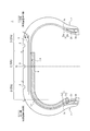
- FIG. 2 is a sectional view in the tire width direction showing a pneumatic radial tire for passenger cars according to an embodiment of the first to third aspects of the present invention.
- FIG. 2 shows a cross-section in the width direction of the tire when the tire is incorporated into a rim, a specified internal pressure is filled, and no load is applied.
- the tire 1 is provided with a carcass 3 made of a ply of a radial arrangement cord, which extends in a toroidal manner between a pair of bead portions 2.
- the tire 1 is provided with a belt 4 and a tread 5, which are two layers of belt layers 4a and 4b in the illustrated example, in that order on the tire radial outside of the carcass 3.
- a bead core 2a is embedded in each of the pair of bead portions 2.
- the cross-sectional shape and the material of the bead core 2a are not particularly limited, and the bead core 2a may have a configuration normally used in a pneumatic radial tire for passenger cars.
- the bead core 2a may be divided into a plurality of small bead cores.
- the bead core 2a may be omitted.
- the tire 1 in the illustrated example has a bead filler 2b having a substantially triangular cross section on the tire radial outside of the bead core 2a.
- the cross-sectional shape of the bead filler 2b is not limited to this example, and the material is not particularly limited. Alternatively, it is possible to reduce the weight of the tire by using the configuration without the bead filler 2b.
- the tire width direction cross-sectional area S1 of the bead filler 2b is preferably 1 to 4 times the tire width direction cross-sectional area S2 of the bead core 2a.
- the ratio Ts/Tb between the gauge Ts of the sidewall portion and the bead width (width of the bead portion 2 in the tire width direction) Tb at the tire radial center position of the bead core 2a is preferably 15% or more and 40% or less. ..
- the ratio Ts/Tb By setting the ratio Ts/Tb to 15% or more, the rigidity of the sidewall portion can be secured.
- the ratio Ts/Tb to 40% or less, the tire can be made lighter and the fuel economy can be improved.
- the gauge Ts is the sum of the thicknesses of all the members such as rubber, the reinforcing member, and the inner liner (however, even when the noise suppressor is arranged on the inner surface of the sidewall portion, the thickness of the noise suppressor is Not included).
- the distance between the innermost end and the outermost end in the tire width direction of all the small bead cores is Tb.
- the ratio Ts/Tc of the gauge Ts of the sidewall portion at the tire maximum width position and the diameter Tc of the carcass cord is 5 or more and 10 or less.
- the rigidity of the sidewall portion can be secured, while setting the ratio Ts/Tc to 10 or less makes the tire lighter and further improves fuel economy. This is because it can be improved.
- the maximum tire width position is, for example, in the range of 50% to 90% in terms of tire cross-sectional height from the bead base line (imaginary line that passes through the bead base and is parallel to the tire width direction) to the tire radial outside.
- the “sidewall portion” refers to a tire radial direction region outside the ground contact end E in the tire width direction and extending from the ground contact end E to the tire radial outer end of the bead portion.
- the tire 1 may have a structure having a rim guard.
- the bead portion 2 may be further provided with an additional member such as a rubber layer or a cord layer for the purpose of reinforcement or the like.
- Such an additional member can be provided at various positions with respect to the carcass 3 and the bead filler 2b.
- the carcass 3 is composed of one carcass ply.
- the number of carcass plies is not particularly limited, and may be two or more.
- the carcass 3 includes a carcass body portion 3a that straddles between the pair of bead portions 2 in a toroidal shape, and a folded portion 3b that is folded from the carcass body portion 3a around the bead core 2a.
- the carcass folded-back portion 3b may be wound around the bead core 2a or may be sandwiched between a plurality of divided small bead cores.
- the end 3c of the carcass folded-back portion 3b is located outside the tire radial direction outer end of the bead filler 2b in the tire radial direction and inside the tire maximum width position in the tire radial direction.
- the end 3c of the carcass folded-back portion 3b may be located on the tire radial direction inner side from the tire radial direction outer end of the bead filler 2b, or on the tire radial direction outer side from the tire maximum width position. It may be located.
- the end 3c of the carcass folded-back portion 3b is positioned inside the tire width direction from the end of the belt 4 (for example, the end of the belt layer 4b) so as to be located between the carcass body 2a and the belt 4 in the tire radial direction. It may also be an envelope structure. Further, when the carcass 3 is composed of a plurality of carcass plies, the positions (for example, tire radial direction positions) of the ends 3c of the carcass folded-back portions 3b may be the same or different between the carcass plies. .
- the number of cords to be driven into the carcass 3 is not particularly limited, but may be, for example, 20 to 60 cords/50 mm. Further, various structures can be adopted for the carcass line.
- the carcass maximum width position can be brought closer to the bead portion 2 side or the tread 5 side in the tire radial direction.
- the carcass maximum width position can be provided outside the bead base line in the tire radial direction in the range of 50% to 90% in terms of the tire cross-sectional height.
- the “radial arrangement” is 85° or more with respect to the tire circumferential direction, and preferably 90° with respect to the tire circumferential direction.
- the tire according to the present embodiment preferably has one or more inclined belt layers formed of rubberized layers of cords that extend obliquely with respect to the tire circumferential direction, and is a compromise between weight reduction and suppression of ground plane shape distortion. It is most preferable to have two layers.
- the belt layer may be a single layer from the viewpoint of weight reduction, or may be three or more layers from the viewpoint of suppressing distortion of the ground contact surface shape.
- the width in the tire width direction of the belt layer 4b on the tire radial direction outer side is smaller than the width of the belt layer 4a on the tire radial direction inner side in the tire width direction. ..
- the width in the tire width direction of the belt layer 4b on the outer side in the tire radial direction can be made larger than or the same as the width of the belt layer 4a on the inner side in the tire radial direction in the tire width direction.
- the width of the belt layer having the largest width in the tire width direction (the belt layer 4a in the illustrated example) in the tire width direction is preferably 90 to 115% of the ground contact width, and 100 to 105% of the ground contact width. Particularly preferred.
- the "ground contact width” means the distance in the tire width direction between the ground contact ends E on the ground contact surface.
- the belt cord of the belt layers 4a and 4b it is most preferable to use a metal cord, particularly a steel cord, as the belt cord of the belt layers 4a and 4b, but an organic fiber cord can also be used.
- the steel cord is mainly composed of steel and may contain various trace contents such as carbon, manganese, silicon, phosphorus, sulfur, copper and chromium.
- the belt cords of the belt layers 4a and 4b may be monofilament cords, cords in which a plurality of filaments are aligned, or cords in which a plurality of filaments are twisted.
- Various twist structures can be adopted, and the cross-sectional structure, twist pitch, twist direction, and distance between adjacent filaments can be various.
- the inclination angle of the belt cords of the belt layers 4a and 4b is preferably 10° or more with respect to the tire circumferential direction.
- the inclination angle of the belt cords of the belt layers 4a and 4b is a high angle, specifically 20° or more, preferably 35° or more, and particularly 55° to the tire circumferential direction with respect to the tire circumferential direction. It is preferably in the range of 85°.
- the inclination angle is set to 20° or more (preferably 35° or more), the rigidity in the tire width direction can be increased, and particularly the steering stability performance during cornering can be improved. Also, it is possible to reduce the shear deformation of the interlayer rubber and reduce the rolling resistance.
- the tire according to the present embodiment has a configuration in which one or more circumferential belt layers including cords extending substantially along the tire circumferential direction are not provided outside the belt 4 in the tire radial direction.
- a configuration in which a circumferential belt composed of one or more circumferential belt layers can be provided outside the belt 4 in the tire radial direction.
- the belt cords of the belt layers 4a and 4b forming the belt 4 have inclination angles ⁇ 1 and ⁇ 2 of 35° or more, it is preferable to provide a circumferential belt, and the circumferential belt is a unit of the center region C.
- the tire circumferential rigidity per width is preferably higher than the tire circumferential rigidity per unit width of the shoulder region S.
- a tire width direction area of the tire width direction center 50% between the ground contact ends E is defined as a center area C
- the tire width direction regions of 25% on both sides in the tire width direction from the center region are defined as shoulder regions S.
- the tire circumferential rigidity per unit width of the center region C can be made smaller than the tire circumferential rigidity per unit width of the shoulder region S. Can be higher.
- the circumferential belt layer when the circumferential belt is provided, the circumferential belt layer preferably has high rigidity, and more specifically, the circumferential belt layer is made of a rubberized layer of a cord extending in the tire circumferential direction.
- the rate is Y (GPa)
- the number of driving is n (pieces/50 mm)
- the circumferential belt layer is m layers
- the cord diameter is d (mm)
- X Y ⁇ n ⁇ m ⁇ d It is preferable that 1500 ⁇ X ⁇ 225.
- the inclination angle of the belt cords of the belt layers 4a and 4b with respect to the tire circumferential direction may be a high angle, specifically, 35° or more. preferable.
- the rigidity in the tire circumferential direction becomes high, which may reduce the ground contact length depending on the tire. Therefore, by using a belt layer with a high angle, it is possible to reduce the out-of-plane bending rigidity in the tire circumferential direction, increase the elongation of the rubber in the tire circumferential direction when the tread deforms, and suppress the decrease in the ground contact length. ..
- a wavy cord may be used for the circumferential belt layer in order to increase the breaking strength.
- a high elongation cord (for example, elongation at break of 4.5 to 5.5%) may be used to increase the breaking strength.
- various materials can be used for the circumferential belt layer, and typical examples are rayon, nylon, polyethylene naphthalate (PEN), polyethylene terephthalate (PET), aramid, glass. Fiber, carbon fiber, steel, etc. can be used. From the viewpoint of weight reduction, organic fiber cords are particularly preferable.
- the cord of the circumferential belt layer is a monofilament cord, a cord in which a plurality of filaments are aligned, a cord in which a plurality of filaments are twisted, and a different material. It is also possible to use a hybrid cord formed by twisting filaments. Further, in the present embodiment, the number of circumferential belt layers to be driven can be set in a range of 20 to 60 lines/50 mm, but the number is not limited to this range.
- the circumferential belt layer may have a width in the tire width direction larger or smaller than that of the belt layers 4a and 4b.
- the width in the tire width direction of the circumferential belt layer is 90% to 110% of the width in the tire width direction of the belt layer (belt layer 4a in the illustrated example) having the largest width in the tire width direction among the belt layers 4a and 4b. It can be %.
- the circumferential belt layer is configured as a spiral layer.
- the tread rubber forming the tread 5 is composed of one layer.
- the tread rubber forming the tread 5 may be formed by laminating a plurality of different rubber layers in the tire radial direction.
- the plurality of rubber layers those having different tangent loss, modulus, hardness, glass transition temperature, material and the like can be used.
- the ratio of the thickness of the plurality of rubber layers in the tire radial direction may be changed in the tire width direction, and only the circumferential main groove bottom or the like may be a rubber layer different from the periphery thereof.
- the tread rubber that constitutes the tread 5 may be formed of a plurality of rubber layers that are different in the tire width direction.
- the plurality of rubber layers those having different tangent loss, modulus, hardness, glass transition temperature, material, etc. can be used. Further, the ratio of the width in the tire width direction of the plurality of rubber layers may be changed in the tire radial direction, and only in the vicinity of the circumferential main groove, only in the vicinity of the ground contact end, only in the shoulder land portion, only in the center land portion, etc. Only a limited part of the area may be a rubber layer different from the surrounding area. Further, in the present embodiment, in the tire width direction cross section, a straight line parallel to the tire width direction passing through the point P on the tread surface CL of the tire equatorial plane CL is defined as a straight line parallel to the tire width direction passing through the ground contact end E.
- the ratio L CR /W is preferably 0.045 or less.
- the tire 1 has three circumferential main grooves 6 extending in the tire circumferential direction. Specifically, one circumferential main groove 6 is provided on the tire equatorial plane CL, and one circumferential main groove 6 is provided in each shoulder region S on both sides in the tire width direction.
- the groove width (opening width) of the circumferential main groove 6 is not particularly limited, but may be, for example, 2 mm to 5 mm. In the present embodiment, it is preferable to reduce the amount of grooves occupying the tread 5 from the viewpoint of achieving both wet performance and other performance.
- the groove volume ratio (groove volume V2/tread rubber volume V1) is preferably 30% or less, and the negative ratio (ratio of the groove area to the tread tread area) is 30% or less.
- the ground contact pressure in the center region C is higher than that in the shoulder region S, so that heat generation in the center region C tends to be relatively large. Therefore, as in the present embodiment, by providing one circumferential main groove 6 in the center region C (on the tire equatorial plane CL in the illustrated example), heat can be efficiently dissipated.
- the heat dissipation is enhanced by having one or more (one in this example) circumferential main groove 6 in each shoulder region S.
- the tread 5 has a land portion continuous in the tire circumferential direction in a region including at least the tire equatorial plane CL of the tread tread surface.
- the number and arrangement of the circumferential main grooves 6 are not particularly limited to the above example.
- a widthwise groove extending in the tire widthwise direction, a sipe closed at the time of contact with the ground, and the like can be appropriately provided.
- the cross-sectional area of each circumferential direction main grooves it is preferably set to 24 mm 2 or more 96 mm 2 or less, the number of the time circumferential main groove, two or more is preferably set to five or less, therefore, the sum of the cross-sectional area of the circumferential main groove in the entire tread surface, it is preferable that the 48 mm 2 or more 480 mm 2 or less.
- the tire 1 of the present embodiment has an inner liner 8 on the inner surface 7 of the tire (hereinafter, also simply referred to as the tire inner surface 7).
- the inner liner 8 preferably has a thickness of about 1.5 mm to 2.8 mm. This is because the vehicle interior noise of 80 to 100 Hz can be effectively reduced.
- the air permeability coefficient of the rubber composition constituting the inner liner 8 is 1.0 ⁇ 10 ⁇ 14 cc ⁇ cm/(cm 2 ⁇ s ⁇ cmHg) or more and 6.5 ⁇ 10 ⁇ 10 cc ⁇ cm/(cm 2 ⁇ S ⁇ cmHg) or less is preferable.
- the inner liner 8 can be formed of a rubber layer mainly containing butyl rubber or a film layer mainly containing resin.
- a sealant member for preventing air leakage at the time of puncture can be provided in a portion of the tire inner surface 7 where the noise suppressor 9 is not arranged.
- the tire 1 of the present embodiment is provided with one or more (one in the illustrated example) noise suppressors 9 on the tire inner surface 7 (in this example, the inner surface of the inner liner 8). ..
- the noise suppressor 9 is a sponge material.
- the noise suppressor 9 is formed from the tire inner surface 7 on the tire width direction inner side with respect to the tire width direction inner half 1/4 point F with the tire equatorial plane CL as a boundary. It extends to the tire inner surface 7 in the bead portion 2 on the other half of the tire width direction.
- the noise suppressor 9 is not provided on the tire inner surface 7 in a region outside the quarter width F of the one half portion in the tire width direction outside the tire width direction.
- one end of the noise suppressor 9 is located 0.5 to 5 mm (1 mm in the illustrated example) inside the tire width direction from the 1/4 point F.
- one end of the noise suppressor 9 may be located at the tire width direction position of the 1/4 point F, or one end of the noise suppressor 9 may be located at the other half of the tire width direction. It may be located on the tire inner surface 7 in the center region C.
- the other end of the noise damper 9 is located on the tire inner surface 7 of the bead portion 2 in the other half portion in the tire width direction.
- the other end of the noise damper 9 may be located on the tire inner surface 7 at the sidewall portion in the other half portion in the tire width direction, or in the other half portion in the tire width direction. It may be located on the tire inner surface 7 in the center region C or the shoulder region S.
- the noise suppressor 9 is adhered to all or part (all in this example) of the tire inner surface 7 provided with the noise suppressor 9 via an adhesive layer (not shown) containing an adhesive.
- an adhesive layer can be used. Alternatively, they may be adhered by fusion or the like. In order to secure the adhesive force, it is preferable to adhere the entire area of the area in contact with the tire inner surface 7 as in this example.
- the noise suppressor 9 can be provided by directly adhering to the tire inner surface 7. Further, it is preferable that the noise suppressor 9 is composed of one noise suppressor 9 in the continuous extending region, but it may be constituted by adhering two or more noise suppressors 9 with an adhesive layer or the like. it can.
- the noise suppressor 9 continuously extends in the tire circumferential direction.
- the noise damper 9 is not divided in the tire circumferential direction, but two or more noise dampers 9 divided in the tire circumferential direction are bonded in the tire circumferential direction with an adhesive layer or the like. You can also do it.
- the noise suppressor 9 may extend discontinuously in the tire circumferential direction. In this case, from the viewpoint of improving the sound damping property, it is preferable that the total extension be 80% or more of the entire area in the tire circumferential direction.
- the noise suppressor 9 when the noise suppressor 9 extends discontinuously in the tire circumferential direction, from the viewpoint of improving the uniformity in the circumferential direction of the tire, the noise suppressor 9 having the same circumferential length is used at equal intervals. It is preferable to arrange at a directional pitch. In the case where the noise dampers 9 are divided in the tire circumferential direction, all the noise dampers 9 are tires in the tire width direction outer side than the quarter point F in one half of the tire width direction. It is preferable that the inner surface 7 is not provided, but it may have a partly different structure.
- the noise suppressor 9 may have any cross-sectional shape.
- the noise suppressor 9 has the same cross-sectional shape and size in any cross section in the tire width direction, but may change in the tire circumferential direction.
- the volume of the noise damper 9 is preferably 0.1% to 80% of the total volume of the tire inner cavity. By setting the volume of the noise suppressor 9 to 0.1% or more with respect to the total volume of the tire inner cavity, the effect of reducing cavity resonance noise can be effectively obtained, while the total volume of the tire inner cavity is reduced. On the other hand, by setting the volume of the noise damper 9 to 80% or less, the weight increase by the noise damper 9 can be suppressed. Further, it is possible to prevent heat from being accumulated in the noise suppressor 9.
- the volume of the noise suppressor 9 is more preferably 5 to 70% of the total volume of the tire inner cavity, and further preferably 15 to 50%.
- dimensions are shown in the figure showing the state where the tire is built into the rim and the specified internal pressure is filled, but the volume of the noise suppressor and the width, thickness, flatness, cross-sectional area, peripheral length, etc., which will be described later, are shown. Indicates that the tire is removed from the rim at room temperature and pressure.
- the peripheral length along the tire inner surface 7 of the noise suppressor 9 was set to L1 (mm), and measurement was performed in a direction orthogonal to the direction along the tire inner surface 7 of the noise suppressor 9.
- the ratio T1/L1 is preferably 0.2 to 0.8.
- the thickness T1 can be increased as compared with the width L1, the volume of the noise suppressor 9 can be secured, and the noise suppressing property can be further improved.
- the ratio T1/L1 to 0.8 or less the thickness T1 is made smaller than the width L1, heat is suppressed from being accumulated in the noise suppressor 9, and tire durability is further improved. Because you can.
- the ratio T1/L1 is more preferably 0.3 to 0.6.
- the maximum thickness T1 of the noise suppressor 9 can be set to 5 to 40 mm in the range of the above ratio T1/L1.
- the ratio S1 (mm 2 )/T1 (mm) is preferably 50 or more and 250 or less.
- the ratio S1 (mm 2 )/T1 (mm) By setting the ratio S1 (mm 2 )/T1 (mm) to be 50 or more, it is possible to increase the cross-sectional area S1 as compared with the thickness T1 and further improve the noise control, while the ratio S1 ( By setting mm 2 )/T1 (mm) to 250 or less, the cross-sectional area S1 is made smaller than the thickness T1, heat is suppressed from being accumulated in the noise suppressor 9, and tire durability is further improved. It can be done. For the same reason, the ratio S1 (mm 2 )/T1 (mm) is more preferably 70 to 150.
- the material forming the noise suppressor 9 can be controlled so as to reduce the cavity resonance energy by relaxation, absorption of the cavity resonance energy, conversion to another energy (for example, thermal energy), or the like.
- another energy for example, thermal energy
- it is not limited to the sponge material described above, and for example, a non-woven fabric made of organic fibers or inorganic fibers may be used.
- the sponge material can be a sponge-like porous structure, and has, for example, open cells formed by foaming rubber or synthetic resin, Including so-called sponge.
- the sponge material includes, in addition to the above-mentioned sponge, a web-shaped material in which animal fibers, plant fibers, synthetic fibers or the like are entwined and integrally connected.
- the above-mentioned “porous structure” is not limited to a structure having open cells, but includes a structure having closed cells. The sponge material as described above converts the vibration energy of air in which the voids formed on the surface and inside vibrate into heat energy.
- the material of the sponge material include synthetic polyurethane resin sponges such as ether polyurethane sponge, ester polyurethane sponge, polyethylene sponge, chloroprene rubber sponge (CR sponge), ethylene propylene rubber sponge (EPDM sponge), nitrile rubber sponge (NBR sponge). ) Such as rubber sponge. From the viewpoints of noise control, lightness, controllability of foaming, durability, etc., it is preferable to use a polyurethane-based or polyethylene-based sponge including an ether-based polyurethane sponge.
- the total cross-sectional area of the noise suppressor 9 in the tire width direction cross section is preferably 20 to 30000 (mm 2 ).
- the total cross-sectional area is 20 (mm 2 ) or more, the sound damping property can be further improved.
- the total cross-sectional area is 30000 (mm 2 ) or less, the noise suppressor 9 is heated. This is because it is possible to suppress the muddyness and further improve the tire durability.
- the total cross-sectional area is more preferably 100 (mm 2 ) to 20000 (mm 2 ), more preferably 1000 (mm 2 ) to 18000 (mm 2 ), and 3000 (mm 2 ) to 15000 (mm 2 ) is more preferable.
- the hardness of the sponge material is not particularly limited, but is preferably in the range of 5N to 450N. By setting the hardness to 5 N or more, the sound damping property can be improved, and by setting the hardness to 450 N or less, the adhesive force of the sound damping body can be increased. Similarly, the hardness of the noise damper is more preferably in the range of 8 to 300N.
- the "hardness” is a value measured according to the A method of 6.3 in the measuring method of 6th item of JIS K6400.
- the specific gravity of the sponge material is preferably 0.001 to 0.090.
- the specific gravity of the sponge material By setting the specific gravity of the sponge material to 0.001 or more, the sound damping property can be improved, and on the other hand, by setting the specific gravity of the sponge material to 0.090 or less, the increase in weight due to the sponge material is suppressed. Because you can.
- the specific gravity of the sponge material is more preferably 0.003 to 0.080.
- the “specific gravity” is a value obtained by converting the apparent density into a specific gravity in accordance with the measuring method of the fifth item of JIS K6400.
- the tensile strength of the sponge material is preferably 20 kPa to 500 kPa.
- the adhesive force can be improved, and on the other hand, by setting the tensile strength to 500 kPa or less, the productivity of the sponge material can be improved.
- the tensile strength of the sponge material is more preferably 40 to 400 kPa.
- the “tensile strength” is a value measured by a No. 1 dumbbell-shaped test piece in accordance with the measuring method of Item 10 of JIS K6400.
- the elongation at break of the sponge material is preferably 110% or more and 800% or less.
- the elongation at break of the sponge material is more preferably 130% or more and 750% or less.
- the "elongation at break” is a value measured with a No. 1 dumbbell-shaped test piece in accordance with the measuring method of Item 10 of JIS K6400.
- the tear strength of the sponge material is preferably 1 to 130 N/cm.
- the tear strength of the sponge material is more preferably 3 to 115 N/cm.
- the “tear strength” is a value measured with a No. 1 type test piece in accordance with the measuring method of Item 11 of JIS K6400.
- the foaming rate of the sponge material is preferably 1% or more and 40% or less.
- the foaming rate of the sponge material is more preferably 2 to 25%.
- the "foaming rate” means a value obtained by subtracting 1 from the ratio A/B of the specific gravity A of the solid phase portion of the sponge material to the specific gravity B of the sponge material and multiplying the value by 100.
- the mass of the sponge material is preferably 5 to 800 g. This is because if the mass is 5 g or more, the sound damping property can be reduced, and if the mass is 800 g or less, the weight increase due to the sponge material can be suppressed. Similarly, the mass of the sponge material is preferably 20 to 600 g.
- the pneumatic radial tire for passenger cars of the present embodiment has the following operational effects by using the "one half portion in the tire width direction" as the outer side when the vehicle is mounted.
- the tire cross-section width SW and the tire outer diameter OD satisfy the above-mentioned predetermined relationship (that is, in the first aspect, the tire cross-section width SW is The cross-sectional width SW of the tire is less than 165 (mm), and the ratio SW/OD of the tire cross-sectional width SW to the outer diameter OD is 0.26 or less. ) It is above, and the cross-sectional width SW (mm) and outer diameter OD (mm) of the tire satisfy the relational expression, OD (mm) ⁇ 2.135 ⁇ SW (mm)+282.3. In the aspect of 3, the relational expression, OD (mm) ⁇ 0.0187 ⁇ SW (mm) 2 +9.15 ⁇ SW (mm) ⁇ 380, is satisfied).
- the fuel efficiency can be improved.
- the tire width direction outer side is closer to the outer side in the vicinity of the 1/4 point when the vehicle is mounted. Buckling tends to be large.
- one or more noise suppressors 9 are provided on the tire inner surface 7, but the noise suppressors 9 are arranged in the tire width direction on one side with the tire equatorial plane CL as a boundary. It is not provided on the tire inner surface 7 in the region outside the quarter width F in the tire width direction in the half of the above.
- the noise suppressor 9 is not provided in a portion having a large back ring, It is possible to suppress peeling from the tire inner surface 7 due to the force applied to the noise damper 9 or melting of the adhesive layer due to heat generated by deformation or the like, and it is possible to improve tire durability.
- the predetermined relationship between the sectional width SW of the tire and the tire outer diameter OD is preferably satisfied when the internal pressure is 200 kPa or more, more preferably 220 kPa or more, and more preferably 280 kPa or more. More preferably, it is satisfied in some cases. This is because the rolling resistance can be further reduced by setting the high internal pressure.
- the predetermined relationship between the sectional width SW of the tire and the tire outer diameter OD is preferably satisfied when the internal pressure is 350 kPa or less. This is because the riding comfort can be improved.
- one end of the noise suppressor 9 is located on the tire width direction inner side of the 1/4 point F in one half of the tire width direction (outer side when the vehicle is mounted), and The end is located on the tire inner surface 7 of the bead portion 2 in the other half portion in the tire width direction (inside when the vehicle is mounted).
- the sidewall portion and the bead portion are deformed (compared with a tire of a normal size). Since it is relatively small, even if it is arranged as described above, the deformation force received by the noise damper 9 is small, and since the heat generation is also small, peeling from the tire inner surface 7 is suppressed and tire durability is improved. be able to. Further, in the present embodiment, a sponge material is used as the noise suppressor 9, and since the sponge material can exhibit high sound damping property despite its small specific gravity, it is possible to prevent an excessive weight increase. The noise control property can be further improved. As described above, according to the pneumatic radial tire for a passenger vehicle of the present embodiment, it is possible to achieve both sound damping and tire durability.
- FIG. 3 is a cross-sectional view in the tire width direction showing a pneumatic radial tire for passenger cars according to another embodiment of the first to third aspects of the present invention.
- FIG. 3 shows a cross-section in the width direction of the tire when the tire is incorporated in a rim, a specified internal pressure is filled, and no load is applied.
- the tire of the other embodiment shown in FIG. 3 is different from the tire of the previous embodiment shown in FIG. 2 only in the arrangement mode and size of the noise suppressor 9. Therefore, the configuration will be described below, and the other configurations will be described. The description of the common configuration is omitted. That is, the tire of the embodiment shown in FIG. 3 is shown in FIG.
- the position of the other end of the noise damper 9 is the position of the tire inner surface 7 in the shoulder region S of the other half of the tire width direction.
- the tire is different from the tire of the embodiment, and other configurations (for example, the position of one end of the noise suppressor 9) are the same.
- the tire of the embodiment shown in FIG. 2 described above is advantageous in that a large volume of the noise suppressor 9 can be secured to enhance the sound damping property, while the tire of the embodiment shown in FIG. Is advantageous in that the weight increase due to the noise suppressor 9 can be reduced.
- one end of the noise suppressor 9 is located at the one-fourth point on one side in the tire width direction or at the inside of the one-fourth point F in the tire width direction.
- the other end of the noise suppressor 9 is preferably located on the tire inner surface 7 of the bead portion 2 in the other half portion in the tire width direction. This is because it is possible to achieve both noise control and tire durability at a higher level.
- the noise suppressor 9 is preferably a sponge material. Since the sponge material has a small specific gravity, it is possible to improve the sound damping property while preventing an excessive increase in weight.
- the tire/rim assembly here is one in which the pneumatic radial tire for a passenger vehicle according to each of the embodiments of the first to third aspects is assembled to a rim. According to the tire/rim assembly, it is possible to obtain the same operational effects as those described for the pneumatic radial tire for a passenger vehicle according to each of the embodiments of the first to third aspects.
- the internal pressure of the tire/rim assembly is preferably 200 kPa or more, more preferably 250 kPa or more, and further preferably 280 kPa or more. This is because the rolling resistance can be further reduced by using a high internal pressure.
- the internal pressure of the tire/rim assembly is preferably 350 kPa or less. This is because the riding comfort can be improved.
- the pneumatic radial tire for passenger cars used here is the pneumatic radial tire for passenger cars according to the respective embodiments of the first to third aspects.
- the same operational effects as those described for the pneumatic radial tire for a passenger vehicle according to the respective embodiments of the first to third aspects can be obtained.
- the internal pressure is preferably 200 kPa or more, more preferably 220 kPa or more, and further preferably 280 kPa or more. This is because the rolling resistance can be further reduced by using a high internal pressure. On the other hand, it is preferable to use the internal pressure of 350 kPa or less. This is because the riding comfort can be improved.
- the present invention is not limited to the above embodiments.
- the thickness of the noise damper 9 is substantially constant, but the thickness of the noise damper 9 may change along the tire inner surface 7.
- Other various modifications are possible.
- SW is less than 165 mm
- the ratio SW/OD is 0.26 or less
- the internal pressure is 200 kPa or more
- the oblateness is 70 or less
- the rim diameter is 18 inches or more
- the sound absorber eg, sponge material
- the "perimeter of the noise suppressor” here means the perimeter at the position where the circumference of the noise suppressor is minimized when measured in the tire circumferential direction, and the noise suppressor is divided into multiple parts. In the case of the sound damping body, it means the circumference of the sound damping body having the smallest circumference.
- the noise damper when divided in the tire circumferential direction, it means the total circumferential length.
- the internal pressure when the internal pressure is set high, the ground contact pressure on the tread tread increases, and the cavity resonance tends to deteriorate. Further, when the flatness is lowered, the belt tension increases and the ground contact pressure on the tread tread increases, so that the cavity resonance tends to be deteriorated.
- the tread width is also narrowed accordingly, so that the cross-sectional area of the noise suppressor is generally reduced and the cavity resonance tends to be deteriorated. Therefore, by increasing the outer diameter of the tire and increasing the circumferential length of the noise suppressor, it is possible to increase the total volume of the noise suppressor without increasing the cross-sectional area of the noise suppressor. Can be suppressed. Furthermore, since the noise suppressor has a small cross-sectional area, the amount of heat generated by the noise suppressor can be suppressed. As described above, according to the above configuration, it is possible to achieve a high level of both cavity resonance reduction, rolling resistance reduction, and heat generation endurance performance.
- the tire/rim assembly has SW of 165 mm or more, satisfies OD (mm) ⁇ 2.135 ⁇ SW (mm)+282.3, and has an internal pressure of 200 kPa or more, and a flatness Is 70 or less, the rim diameter is 18 inches or more, and the peripheral length of the noise damper (eg, sponge material) is 1800 mm or more.
- the noise damper eg, sponge material
- the tire/rim assembly satisfies OD (mm) ⁇ 0.0187 ⁇ SW(mm) 2 +9.15 ⁇ SW(mm) ⁇ 380, and has an internal pressure of 200 kPa or more, Further, it is preferable that the flatness is 70 or less, the rim diameter is 18 inches or more, and the circumferential length of the noise damper (eg, sponge material) is 1800 mm or more.
- the noise damper eg, sponge material
Abstract
本発明の乗用車用空気入りラジアルタイヤは、一対のビード部間でトロイダル状に跨る、ラジアル配列コードのプライからなるカーカスを備え、前記タイヤの断面幅SW(mm)及び外径OD(mm)は、所定の関係式を満たし、前記タイヤの内面に、1つ以上の制音体を設け、前記制音体は、タイヤ赤道面を境界とするタイヤ幅方向一方の半部における前記1/4点よりもタイヤ幅方向外側の領域での前記タイヤの内面には、設けられていない。
Description
本発明は、乗用車用空気入りラジアルタイヤに関するものである。
本出願人は、タイヤの断面幅SWとタイヤの外径ODとを所定の関係とした、狭幅かつ大径の乗用車用空気入りラジアルタイヤを種々提案している(例えば、特許文献1)。
ここで、乗用車用空気入りラジアルタイヤ(特に、電気自動車用の空気入りラジアルタイヤ)では、タイヤ騒音の低減が求められている。そして、タイヤ騒音の一つとして、路面を走行した際に50~400Hzの周波数範囲での音が生じる、いわゆるロードノイズが知られている。その主な原因としては、タイヤ内腔内で生じる空気やガスの共鳴振動(空洞共鳴)がある。これに対し、タイヤの内面に、スポンジ材等からなる制音体を配置することが知られている(例えば、特許文献2)。制音体は、タイヤ内腔内での空気やガスの振動エネルギーを熱エネルギーへと変換し、タイヤ内腔内での空洞共鳴を抑制することができる。
しかしながら、制音性を高めようとして、タイヤの内面に上記のような制音体を設けた際に、制音体に熱がこもり、例えば長時間走行後に、制音体とタイヤ内面とを接着する接着層が溶けて、制音体がタイヤ内面から剥離したり、あるいは、タイヤ部材に故障が生じやすくなったりする等、タイヤ耐久性が低下してしまう場合があった。このように、通常、制音性とタイヤ耐久性を両立することは困難であった。
そこで、本発明は、制音性とタイヤ耐久性とを両立させた、乗用車用空気入りラジアルタイヤを提供することを目的とする。
本発明の要旨構成は、以下の通りである。
第1の態様において、本発明の乗用車用空気入りラジアルタイヤは、
一対のビード部間でトロイダル状に跨る、ラジアル配列コードのプライからなるカーカスを備えた、乗用車用空気入りラジアルタイヤであって、
前記タイヤの断面幅SWが165(mm)未満であり、前記タイヤの断面幅SWと外径ODとの比SW/ODは、0.26以下であり、
前記タイヤの内面に、1つ以上の制音体を設け、
前記タイヤをリムに組み込み、規定内圧を充填し、無負荷状態とした際の、タイヤ幅方向断面において、タイヤ赤道面から接地端までのタイヤ幅方向領域でのタイヤ幅方向の中点を、1/4点とするとき、
前記制音体は、タイヤ赤道面を境界とするタイヤ幅方向一方の半部における前記1/4点よりもタイヤ幅方向外側の領域での前記タイヤの内面には、設けられていないことを特徴とする。
ここで、「リム」とは、タイヤが生産され、使用される地域に有効な産業規格であって、日本ではJATMA(日本自動車タイヤ協会)のJATMA YEAR BOOK、欧州ではETRTO(The European Tyre and Rim Technical Organisation)のSTANDARDS MANUAL、米国ではTRA(The Tire and Rim Association,Inc.)のYEAR BOOK等に記載されているまたは将来的に記載される、適用サイズにおける標準リム(ETRTOのSTANDARDS MANUALではMeasuring Rim、TRAのYEAR BOOKではDesign Rim)を指す(即ち、上記の「リム」には、現行サイズに加えて将来的に上記産業規格に含まれ得るサイズも含む。「将来的に記載されるサイズ」の例としては、ETRTO 2013年度版において「FUTURE DEVELOPMENTS」として記載されているサイズを挙げることができる。)が、上記産業規格に記載のないサイズの場合は、タイヤのビード幅に対応した幅のリムをいう。
また、「規定内圧」とは、上記JATMA等に記載されている、適用サイズ・プライレーティングにおける単輪の最大負荷能力に対応する空気圧(最高空気圧)を指し、上記産業規格に記載のないサイズの場合は、「規定内圧」は、タイヤを装着する車両毎に規定される最大負荷能力に対応する空気圧(最高空気圧)をいうものとする。さらに、後述の「最大負荷荷重」とは、上記最大負荷能力に対応する荷重をいうものとする。
また、「規定内圧」とは、上記JATMA等に記載されている、適用サイズ・プライレーティングにおける単輪の最大負荷能力に対応する空気圧(最高空気圧)を指し、上記産業規格に記載のないサイズの場合は、「規定内圧」は、タイヤを装着する車両毎に規定される最大負荷能力に対応する空気圧(最高空気圧)をいうものとする。さらに、後述の「最大負荷荷重」とは、上記最大負荷能力に対応する荷重をいうものとする。
また、「接地端」とは、上記タイヤをリムに組み込み、規定内圧を充填し、最大負荷荷重を負荷した際に、路面と接する接地面のタイヤ幅方向両端を意味する。
以下、特に断りのない限り、寸法等は、上記タイヤをリムに組み込み、規定内圧を充填し、無負荷とした状態での寸法等を意味する。
以下、特に断りのない限り、寸法等は、上記タイヤをリムに組み込み、規定内圧を充填し、無負荷とした状態での寸法等を意味する。
第2の態様において、本発明の乗用車用空気入りラジアルタイヤは、
一対のビード部間でトロイダル状に跨る、ラジアル配列コードのプライからなるカーカスを備えた、乗用車用空気入りラジアルタイヤであって、
前記タイヤの断面幅SWが165(mm)以上であり、前記タイヤの断面幅SW(mm)及び外径OD(mm)は、関係式、
OD(mm)≧2.135×SW(mm)+282.3
を満たし、
前記タイヤの内面に、1つ以上の制音体を設け、
前記タイヤをリムに組み込み、規定内圧を充填し、無負荷状態とした際の、タイヤ幅方向断面において、タイヤ赤道面から接地端までのタイヤ幅方向領域でのタイヤ幅方向の中点を、1/4点とするとき、
前記制音体は、タイヤ赤道面を境界とするタイヤ幅方向一方の半部における前記1/4点よりもタイヤ幅方向外側の領域での前記タイヤの内面には、設けられていないことを特徴とする。
第3の態様において、本発明の乗用車用空気入りラジアルタイヤは、
一対のビード部間でトロイダル状に跨る、ラジアル配列コードのプライからなるカーカスを備えた、乗用車用空気入りラジアルタイヤであって、
前記タイヤの断面幅SW(mm)及び外径OD(mm)は、関係式、
OD(mm)≧-0.0187×SW(mm)2+9.15×SW(mm)-380
を満たし、
前記タイヤの内面に、1つ以上の制音体を設け、
前記タイヤをリムに組み込み、規定内圧を充填し、無負荷状態とした際の、タイヤ幅方向断面において、タイヤ赤道面から接地端までのタイヤ幅方向領域でのタイヤ幅方向の中点を、1/4点とするとき、
前記制音体は、タイヤ赤道面を境界とするタイヤ幅方向一方の半部における前記1/4点よりもタイヤ幅方向外側の領域での前記タイヤの内面には、設けられていないことを特徴とする。
本明細書において、「ビード部」とは、ビードフィラを有する場合には、リムベースラインからビードフィラのタイヤ径方向最外側端までのタイヤ径方向領域にある部分をいい、ビードフィラを有しない場合には、リムベースラインからビードコアのタイヤ径方向最外側端までのタイヤ径方向領域にある部分をいう。
本発明によれば、制音性とタイヤ耐久性とを両立させた、乗用車用空気入りラジアルタイヤを提供することができる。
以下、本発明の実施形態について、図面を参照して詳細に例示説明する。
<乗用車用空気入りラジアルタイヤ>
図1は、タイヤの断面幅SW及び外径ODを示す概略図である。
本発明の第1の態様における一実施形態の乗用車用空気入りラジアルタイヤ(以下、単にタイヤとも称する)は、タイヤの断面幅SWが165(mm)未満であり、タイヤの断面幅SWと外径ODとの比SW/ODは、0.26以下であり、狭幅・大径の形状をなしている。タイヤの断面幅SWをタイヤの外径ODに比して狭くすることにより、空気抵抗を低減することができ、且つ、タイヤの外径ODをタイヤの断面幅SWに比して大きくすることにより、タイヤの接地面付近でのトレッドゴムの変形を抑制して、転がり抵抗を低減することができ、これらにより、タイヤの燃費性を向上させることができる。上記SW/ODは、0.25以下とすることが好ましく、0.24以下とすることがより好ましい。
上記比は、タイヤの内圧が200kPa以上である場合に満たされるものであることが好ましく、220kPa以上である場合に満たされるものであることがより好ましく、280kPa以上である場合に満たされるものであることがさらに好ましい。転がり抵抗を低減することができるからである。一方で、上記比は、タイヤの内圧が350kPa以下である場合に満たされるものであることが好ましい。乗り心地性を向上させることができるからである。
ここで、タイヤの断面幅SWは、接地面積を確保する観点からは、上記比を満たす範囲において、105mm以上とすることが好ましく、125mm以上とすることがより好ましく、135mm以上とすることがさらに好ましく、145mm以上とすることが特に好ましい。一方で、タイヤの断面幅SWは、空気抵抗を低減する観点からは、上記比を満たす範囲において、155mm以下とすることが好ましい。また、タイヤの外径ODは、転がり抵抗を低減する観点からは、上記比を満たす範囲において、500mm以上とすることが好ましく、550mm以上とすることがより好ましく、580mm以上とすることがさらに好ましい。一方で、タイヤの外径ODは、空気抵抗を低減する観点からは、上記比を満たす範囲において、800mm以下とすることが好ましく、720mm以下とすることがより好ましく、650mm以下とすることがさらに好ましく、630mm以下とすることが特に好ましい。また、リム径は、転がり抵抗を低減する観点からは、タイヤの断面幅SW及び外径ODが上記比を満たすとき、16インチ以上とすることが好ましく、17インチ以上とすることがより好ましく、18インチ以上とすることがさらに好ましい。一方で、リム径は、空気抵抗を低減する観点からは、タイヤの断面幅SW及び外径ODが上記比を満たすとき、22インチ以下とすることが好ましく、21インチ以下とすることがより好ましく、20インチ以下とすることがさらに好ましく、19インチ以下とすることが特に好ましい。また、タイヤの扁平率は、タイヤの断面幅SW及び外径ODが上記比を満たすとき、45~70とすることがより好ましく、45~65とすることがより好ましい。
具体的なタイヤサイズは、特に限定されるものではないが、一例として、105/50R16、115/50R17、125/55R20、125/60R18、125/65R19、135/45R21、135/55R20、135/60R17、135/60R18、135/60R19、135/65R19、145/45R21、145/55R20、145/60R16、145/60R17、145/60R18、145/60R19、145/65R19、155/45R18、155/45R21、155/55R18、155/55R19、155/55R21、155/60R17、155/65R18、155/70R17、155/70R19のいずれかとすることができる。
本発明の第2の態様における一実施形態のタイヤは、タイヤの断面幅SWが165(mm)以上であり、タイヤの断面幅SW(mm)及び外径OD(mm)は、関係式、
OD(mm)≧2.135×SW(mm)+282.3
を満たしており、狭幅・大径の形状をなしている。
上記の関係式を満たすことにより、空気抵抗を低減することができ、且つ、転がり抵抗を低減することができ、これらにより、タイヤの燃費性を向上させることができる。
なお、第2の態様において、タイヤの断面幅SW及び外径ODは、上記の関係式を満たした上で、比SW/ODが0.26以下であることが好ましく、0.25以下であることがより好ましく、0.24以下であることがさらに好ましい。タイヤの燃費性をさらに向上させることができるからである。
上記関係式及び/又は比は、タイヤの内圧が200kPa以上である場合に満たされるものであることが好ましく、220kPa以上である場合に満たされるものであることがより好ましく、280kPa以上である場合に満たされるものであることがさらに好ましい。転がり抵抗を低減することができるからである。一方で、上記関係式及び/又は比は、タイヤの内圧が350kPa以下である場合に満たされるものであることが好ましい。乗り心地性を向上させることができるからである。
ここで、タイヤの断面幅SWは、接地面積を確保する観点からは、上記関係式を満たす範囲において、175mm以上とすることが好ましく、185mm以上とすることがより好ましい。一方で、タイヤの断面幅SWは、空気抵抗を低減する観点からは、上記関係式を満たす範囲において、230mm以下とすることが好ましく、215mm以下とすることがより好ましく、205mm以下とすることがさらに好ましく、195mm以下とすることが特に好ましい。また、タイヤの外径ODは、転がり抵抗を低減する観点からは、上記関係式を満たす範囲において、630mm以上とすることが好ましく、650mm以上とすることがより好ましい。一方で、タイヤの外径ODは、空気抵抗を低減する観点からは、上記関係式を満たす範囲において、800mm以下とすることが好ましく、750mm以下とすることがより好ましく、720mm以下とすることがさらに好ましい。また、リム径は、転がり抵抗を低減する観点からは、タイヤの断面幅SW及び外径ODが上記関係式を満たすとき、18インチ以上とすることが好ましく、19インチ以上とすることがより好ましい。一方で、リム径は、空気抵抗を低減する観点からは、タイヤの断面幅SW及び外径ODが上記関係式を満たすとき、22インチ以下とすることが好ましく、21インチ以下とすることがより好ましい。また、タイヤの扁平率は、タイヤの断面幅SW及び外径ODが上記関係式を満たすとき、45~70とすることが好ましく、45~65とすることがより好ましい。
具体的なタイヤサイズは、特に限定されるものではないが、一例として、165/45R22、165/55R18、165/55R19、165/55R20、165/55R21、165/60R19、165/65R19、165/70R18、175/45R23、175/55R19、175/55R20、175/55R22、175/60R18、185/45R22、185/50R20、185/55R19、185/55R20、185/60R19、185/60R20、195/50R20、195/55R20、195/60R19、205/50R21、205/55R20、215/50R21のいずれかとすることができる。
本発明の第3の態様における一実施形態のタイヤは、タイヤの断面幅SW(mm)及び外径OD(mm)は、関係式、
OD(mm)≧-0.0187×SW(mm)2+9.15×SW(mm)-380
を満たしており、狭幅・大径の形状をなしている。
上記の関係式を満たすことにより、空気抵抗を低減することができ、且つ、転がり抵抗を低減することができ、これらにより、タイヤの燃費性を向上させることができる。
なお、第3の態様において、タイヤの断面幅SW及び外径ODは、上記の関係式を満たした上で、比SW/ODが0.26以下であることが好ましく、0.25以下であることがより好ましく、0.24以下であることがさらに好ましい。タイヤの燃費性をさらに向上させることができるからである。
上記関係式及び/又は比は、タイヤの内圧が200kPa以上である場合に満たされるものであることが好ましく、220kPa以上である場合に満たされるものであることがより好ましく、280kPa以上である場合に満たされるものであることがさらに好ましい。転がり抵抗を低減することができるからである。一方で、上記関係式及び/又は比は、タイヤの内圧が350kPa以下である場合に満たされるものであることが好ましい。乗り心地性を向上させることができるからである。
ここで、タイヤの断面幅SWは、接地面積を確保する観点からは、上記関係式を満たす範囲において、105mm以上とすることが好ましく、125mm以上とすることがより好ましく、135mm以上とすることがさらに好ましく、145mm以上とすることが特に好ましい。一方で、タイヤの断面幅SWは、空気抵抗を低減する観点からは、上記関係式を満たす範囲において、230mm以下とすることが好ましく、215mm以下とすることがより好ましく、205mm以下とすることがさらに好ましく、195mm以下とすることが特に好ましい。また、タイヤの外径ODは、転がり抵抗を低減する観点からは、上記関係式を満たす範囲において、500mm以上とすることが好ましく、550mm以上とすることがより好ましく、580mm以上とすることがさらに好ましい。一方で、タイヤの外径ODは、空気抵抗を低減する観点からは、上記関係式を満たす範囲において、800mm以下とすることが好ましく、750mm以下とすることがより好ましく、720mm以下とすることがさらに好ましい。また、リム径は、転がり抵抗を低減する観点からは、タイヤの断面幅SW及び外径ODが上記関係式を満たすとき、16インチ以上とすることが好ましく、17インチ以上とすることがより好ましく、18インチ以上とすることがさらに好ましい。一方で、リム径は、空気抵抗を低減する観点からは、タイヤの断面幅SW及び外径ODが上記関係式を満たすとき、22インチ以下とすることが好ましく、21インチ以下とすることがより好ましく、20インチ以下とすることがさらに好ましい。また、タイヤの扁平率は、タイヤの断面幅SW及び外径ODが上記関係式を満たすとき、45~70とすることがより好ましく、45~65とすることがより好ましい。
具体的なタイヤサイズは、特に限定されるものではないが、一例として、105/50R16、115/50R17、125/55R20、125/60R18、125/65R19、135/45R21、135/55R20、135/60R17、135/60R18、135/60R19、135/65R19、145/45R21、145/55R20、145/60R16、145/60R17、145/60R18、145/60R19、145/65R19、155/45R18、155/45R21、155/55R18、155/55R19、155/55R21、155/60R17、155/65R18、155/70R17、155/70R19、165/45R22、165/55R18、165/55R19、165/55R20、165/55R21、165/60R19、165/65R19、165/70R18、175/45R23、175/55R18、175/55R19、175/55R20、175/55R22、175/60R18、185/45R22、185/50R20、185/55R19、185/55R20、185/60R19、185/60R20、195/50R20、195/55R20、195/60R19、205/50R21、205/55R20、215/50R21のいずれかとすることができる。
図2は、本発明の第1~第3の態様の一実施形態にかかる乗用車用空気入りラジアルタイヤを示す、タイヤ幅方向断面図である。図2は、タイヤをリムに組み込み、規定内圧を充填し、無負荷とした際のタイヤの幅方向断面を示している。図2に示すように、このタイヤ1は、一対のビード部2間でトロイダル状に跨る、ラジアル配列コードのプライからなるカーカス3を備えている。また、このタイヤ1は、カーカス3のタイヤ径方向外側に、図示例で2層のベルト層4a、4bからなるベルト4及びトレッド5を順に備えている。
この例では、一対のビード部2には、ビードコア2aがそれぞれ埋設されている。本発明では、ビードコア2aの断面形状や材質は特に限定されず、乗用車用空気入りラジアルタイヤにおいて通常用いられる構成とすることができる。本発明では、ビードコア2aは、複数の小ビードコアに分割されたものとすることもできる。あるいは、本発明では、ビードコア2aを有しない構成とすることもできる。
図示例のタイヤ1は、ビードコア2aのタイヤ径方向外側に、断面略三角形状のビードフィラ2bを有している。ビードフィラ2bの断面形状は、この例に限定されるものではなく、材質も特に限定されない。あるいは、ビードフィラ2bを有しない構成としてタイヤを軽量化することもできる。
本実施形態において、ビードフィラ2bのタイヤ幅方向断面積S1は、ビードコア2aのタイヤ幅方向断面積S2の1倍以上4倍以下とすることが好ましい。上記断面積S1を上記断面積S2の1倍以上とすることにより、ビード部2の剛性を確保することができ、上記断面積S1を上記断面積S2の4倍以下とすることにより、タイヤを軽量化して燃費性をさらに向上させることができるからである。また、本実施形態において、タイヤ最大幅位置(タイヤ幅方向の幅が最大となるタイヤ径方向位置であって、それがタイヤ径方向領域となる場合は、その領域のタイヤ径方向中心位置)におけるサイドウォール部のゲージTsと、ビードコア2aのタイヤ径方向中心位置におけるビード幅(ビード部2のタイヤ幅方向の幅)Tbとの比Ts/Tbを、15%以上40%以下とすることが好ましい。上記比Ts/Tbを15%以上とすることにより、サイドウォール部の剛性を確保することができ、一方で、上記比Ts/Tbを40%以下とすることにより、タイヤを軽量化して燃費性をさらに向上させることができるからである。なお、ゲージTsはゴム、補強部材、インナーライナーなど全ての部材の厚みの合計となる(ただし、サイドウォール部の内面に制音体が配置されている場合であっても、制音体の厚さは含まない)。また、ビードコア2aがカーカス3によって複数の小ビードコアに分割されている構造の場合には、全小ビードコアのうちタイヤ幅方向最内側端部と最外側端部の距離をTbとする。また、本実施形態では、タイヤ最大幅位置におけるサイドウォール部のゲージTsと、カーカスコードの径Tcとの比Ts/Tcを5以上10以下とすることが好ましい。上記比Ts/Tcを5以上とすることにより、サイドウォール部の剛性を確保することができ、一方で、上記比Ts/Tcを10以下とすることにより、タイヤを軽量化して燃費性をさらに向上させることができるからである。本実施形態では、タイヤ最大幅位置は、例えば、ビードベースライン(ビードベースを通りタイヤ幅方向に平行な仮想線)からタイヤ径方向外側に、タイヤ断面高さ対比で50%~90%の範囲に設けることができる。
ここで、「サイドウォール部」とは、接地端Eのタイヤ幅方向外側であって、接地端Eからビード部のタイヤ径方向外側端までにかけてのタイヤ径方向領域をいう。
ここで、「サイドウォール部」とは、接地端Eのタイヤ幅方向外側であって、接地端Eからビード部のタイヤ径方向外側端までにかけてのタイヤ径方向領域をいう。
本実施形態では、タイヤ1は、リムガードを有する構造とすることもできる。また、本実施形態では、ビード部2には補強等を目的としてゴム層やコード層等の追加部材をさらに設けることもできる。このような追加部材はカーカス3やビードフィラ2bに対して様々な位置に設けることができる。
図2に示す例では、カーカス3は、1枚のカーカスプライからなる。一方で、本発明では、カーカスプライの枚数は特に限定されず、2枚以上とすることもできる。また、図2に示す例では、カーカス3は、一対のビード部2間をトロイダル状に跨るカーカス本体部3aと、該カーカス本体部3aからビードコア2a周りに折り返されてなる折り返し部3bと、を有している。一方で、本発明では、カーカス折り返し部3bは、ビードコア2aに巻き付けることもでき、あるいは、分割された複数の小ビードコアで挟みこむ構造とすることもできる。図示例では、カーカス折り返し部3bの端3cは、ビードフィラ2bのタイヤ径方向外側端よりタイヤ径方向外側、且つ、タイヤ最大幅位置よりタイヤ径方向内側に位置している。これにより、サイドウォール部の剛性を確保しつつも、タイヤを軽量化することができる。一方で、本発明においては、カーカス折り返し部3bの端3cは、ビードフィラ2bのタイヤ径方向外側端よりタイヤ径方向内側に位置していても良く、あるいは、タイヤ最大幅位置よりタイヤ径方向外側に位置していても良い。あるいは、カーカス折り返し部3bの端3cは、カーカス本体部2aとベルト4とのタイヤ径方向の間に位置するように、ベルト4の端(例えばベルト層4bの端)よりタイヤ幅方向内側に位置する、エンベロープ構造とすることもできる。さらに、カーカス3が複数枚のカーカスプライで構成される場合には、カーカスプライ間で、カーカス折り返し部3bの端3cの位置(例えばタイヤ径方向位置)を同じとすることも異ならせることもできる。カーカス3のコードの打ち込み数としては、特に限定されるものではないが、例えば、20~60本/50mmの範囲とすることができる。また、カーカスラインには様々な構造を採用することができる。例えば、タイヤ径方向において、カーカス最大幅位置をビード部2側に近づけることも、トレッド5側に近づけることもできる。例えば、カーカス最大幅位置は、ビードベースラインからタイヤ径方向外側に、タイヤ断面高さ対比で50%~90%の範囲に設けることができる。上記「ラジアル配列」は、タイヤ周方向に対して85°以上、好ましくはタイヤ周方向に対して90°である。
本実施形態のタイヤは、タイヤ周方向に対して傾斜して延びるコードのゴム引き層からなる1層以上の傾斜ベルト層を有することが好ましく、軽量化と接地面形状の歪みの抑制との兼ね合いから2層とすることが最も好ましい。なお、軽量化の観点からはベルト層を1層とすることもでき、接地面形状の歪みを抑制する観点からは3層以上とすることもできる。図2に示す例では、2層のベルト層4a、4bのうち、タイヤ径方向外側のベルト層4bのタイヤ幅方向の幅は、タイヤ径方向内側のベルト層4aのタイヤ幅方向の幅より小さい。一方で、タイヤ径方向外側のベルト層4bのタイヤ幅方向の幅は、タイヤ径方向内側のベルト層4aのタイヤ幅方向の幅より大きくすることもでき、同じとすることもできる。タイヤ幅方向の幅が最も大きいベルト層(図示例ではベルト層4a)のタイヤ幅方向の幅は、接地幅の90~115%であることが好ましく、接地幅の100~105%であることが特に好ましい。なお、「接地幅」とは、上記接地面における上記接地端E間のタイヤ幅方向の距離をいう。
本実施形態において、ベルト層4a、4bのベルトコードとしては、金属コード、特にスチールコードを用いるのが最も好ましいが、有機繊維コードを用いることもできる。スチールコードはスチールを主成分とし、炭素、マンガン、ケイ素、リン、硫黄、銅、クロムなど種々の微量含有物を含むことができる。本実施形態において、ベルト層4a、4bのベルトコードはモノフィラメントコードや、複数のフィラメントを引き揃えたコード、複数のフィラメントを撚り合せたコードを用いることができる。撚り構造も種々のものを採用することができ、断面構造、撚りピッチ、撚り方向、隣接するフィラメント同士の距離も様々なものとすることができる。さらには異なる材質のフィラメントを撚り合せたコードを用いることもでき、断面構造としても特に限定されず、単撚り、層撚り、複撚りなど様々な撚り構造を取ることができる。
本実施形態では、ベルト層4a、4bのベルトコードの傾斜角度は、タイヤ周方向に対して10°以上とすることが好ましい。本実施形態では、ベルト層4a、4bのベルトコードの傾斜角度を高角度、具体的にはタイヤ周方向に対して20°以上、好ましくは35°以上、特にタイヤ周方向に対して55°~85°の範囲とすることが好ましい。傾斜角度を20°以上(好ましくは35°以上)とすることにより、タイヤ幅方向に対する剛性を高め、特にコーナリング時の操縦安定性能を向上させることができるからである。また、層間ゴムのせん断変形を減少させて、転がり抵抗を低減することができるからである。
本実施形態のタイヤは、ベルト4のタイヤ径方向外側に、タイヤ周方向にほぼ沿って延びるコードからなる1層以上の周方向ベルト層を有しない構成としている。一方で、本発明においては、ベルト4のタイヤ径方向外側に、1層以上の周方向ベルト層からなる周方向ベルトを有する構成とすることもできる。特に、ベルト4を構成するベルト層4a、4bのベルトコードの傾斜角度θ1、θ2が35°以上の場合には、周方向ベルトを設けることが好ましく、該周方向ベルトは、センター領域Cの単位幅あたりのタイヤ周方向剛性が、ショルダー領域Sの単位幅あたりのタイヤ周方向剛性より高いことが好ましい。
なお、タイヤをリムに組み込み、規定内圧を充填し、無負荷状態とした際の、タイヤ幅方向断面において、接地端E間のタイヤ幅方向中央50%のタイヤ幅方向領域をセンター領域Cとし、該センター領域よりタイヤ幅方向両外側の25%ずつのタイヤ幅方向領域をショルダー領域Sとしている。
例えば、センター領域Cにおける周方向ベルト層の層数をショルダー領域Sより多くすることにより、センター領域Cの単位幅あたりのタイヤ周方向剛性を、ショルダー領域Sの単位幅あたりのタイヤ周方向剛性より高くすることができる。ここで、ベルト層4a、4bのベルトコードがタイヤ周方向に対して35°以上で傾斜するタイヤの多くは、400Hz~2kHzの高周波域において、断面方向の1次、2次および3次等の振動モードにて、トレッド踏面が一律に大きく振動する形状となるため、大きな放射音が生じる。そこで、トレッド5のセンター領域Cのタイヤ周方向剛性を局所的に増加させると、トレッド5のセンター領域Cがタイヤ周方向に広がり難くなり、トレッド踏面のタイヤ周方向への広がりが抑制される結果、放射音を減少させることができる。
本実施形態では、タイヤ幅方向の幅が最も広いベルト層(図示例ではベルト層4a)のベルトコードのタイヤ周方向に対する傾斜角度θ1と、タイヤ幅方向の幅が最も狭いベルト層(図示例ではベルト層4b)のベルトコードのタイヤ周方向に対する傾斜角度θ2とが、35°≦θ1≦85°、10°≦θ2≦30°、及び、θ1>θ2を満たすことも好ましい。タイヤ周方向に対して35°以上で傾斜するベルトコードを有するベルト層を備えたタイヤの多くは、400Hz~2kHzの高周波域において、断面方向の1次、2次および3次等の振動モードにて、トレッド踏面が一律に大きく振動する形状となるため、大きな放射音が生じる。そこで、トレッド5のセンター領域Cのタイヤ周方向剛性を局所的に増加させると、トレッド5のセンター領域Cがタイヤ周方向に広がり難くなり、トレッド踏面のタイヤ周方向への広がりが抑制される結果、放射音を減少させることができる。
ここで、本実施形態では、周方向ベルトを設ける場合は、周方向ベルト層は高剛性であることが好ましく、より具体的にはタイヤ周方向に延びるコードのゴム引き層からなり、コードのヤング率をY(GPa)、打ち込み数をn(本/50mm)とし、周方向ベルト層をm層とし、コード径をd(mm)として、X=Y×n×m×dと定義するとき、1500≧X≧225であることが好ましい。狭幅・大径サイズの乗用車用空気入りラジアルタイヤにおいては、路面からの旋回時における入力に対しタイヤ周方向において局所的な変形を起こし、接地面は略三角形状、すなわち、タイヤ幅方向の位置によって周方向の接地長が大きく変化する形状となりやすい。これに対し、高剛性の周方向ベルト層とすることにより、タイヤのリング剛性が向上して、タイヤ周方向の変形が抑制されることとなるため、ゴムの非圧縮性により、タイヤ幅方向の変形も抑制され、接地形状が変化しにくくなる。さらには、リング剛性が向上することにより偏心変形が促進され、転がり抵抗も同時に向上する。さらに、上記のように高剛性の周方向ベルト層を用いた場合には、ベルト層4a、4bのベルトコードのタイヤ周方向に対する傾斜角度を高角度、具体的には35°以上とすることが好ましい。高剛性の周方向ベルト層を用いた場合には、タイヤ周方向の剛性が高くなることにより、タイヤによっては、接地長が減少してしまうことがある。そこで、高角度のベルト層を用いることにより、タイヤ周方向の面外曲げ剛性を低下させて、踏面変形時のゴムのタイヤ周方向の伸びを増大させ、接地長の減少を抑制することができる。また、本実施形態では、周方向ベルト層には、破断強度を高めるために波状のコードを用いてもよい。同様に破断強度を高めるために、ハイエロンゲーションコード(例えば破断時の伸びが4.5~5.5%)を用いてもよい。さらに、本実施形態では、周方向ベルト層には、種々の材質が採用可能であり、代表的な例としては、レーヨン、ナイロン、ポリエチレンナフタレート(PEN)、ポリエチレンテレフタレート(PET)、アラミド、ガラス繊維、カーボン繊維、スチール等が採用できる。軽量化の点から、有機繊維コードが特に好ましい。ここで、本実施形態では、周方向ベルトを設ける場合は、周方向ベルト層のコードは、モノフィラメントコードや、複数のフィラメントを引き揃えたコード、複数のフィラメントを撚り合せたコード、さらには異なる材質のフィラメントを撚り合せたハイブリッドコードを用いることもできる。また、本実施形態では、周方向ベルト層の打ち込み数は、20~60本/50mmの範囲とすることができるが、この範囲に限定されるのもではない。さらに、本実施形態では、タイヤ幅方向に剛性・材質・層数・打ち込み密度等の分布を持たせることもでき、例えばショルダー部Sのみにおいて、周方向ベルト層の層数を増やすこともでき、一方でセンター領域Cのみにおいて、周方向ベルト層の層数を増やすこともできる。また、本実施形態では、周方向ベルト層は、ベルト層4a、4bよりもタイヤ幅方向の幅を大きくすることも小さくすることも同じとすることもできる。例えば、周方向ベルト層のタイヤ幅方向の幅は、ベルト層4a、4bのうちタイヤ幅方向の幅が最も広いベルト層(図示例ではベルト層4a)のタイヤ幅方向の幅の90%~110%とすることができる。ここで、周方向ベルト層は、スパイラル層として構成することが製造の観点から特に有利である。
図示例では、トレッド5を構成するトレッドゴムは、1層からなる。一方で、本実施形態では、トレッド5を構成するトレッドゴムは、異なる複数のゴム層がタイヤ径方向に積層されて形成されていても良い。上記の複数のゴム層としては正接損失、モジュラス、硬度、ガラス転移温度、材質等が異なっているものを用いることができる。また、複数のゴム層のタイヤ径方向の厚さの比率は、タイヤ幅方向に変化していてもよく、また周方向主溝底のみ等をその周辺と異なるゴム層とすることもできる。また、トレッド5を構成するトレッドゴムは、タイヤ幅方向に異なる複数のゴム層で形成されていても良い。上記の複数のゴム層としては正接損失、モジュラス、硬度、ガラス転移温度、材質等が異なっているものを使用することができる。また、複数のゴム層のタイヤ幅方向の幅の比率は、タイヤ径方向に変化していてもよく、また周方向主溝近傍のみ、接地端近傍のみ、ショルダー陸部のみ、センター陸部のみといった限定された一部の領域のみをその周囲とは異なるゴム層とすることもできる。
また、本実施形態では、タイヤ幅方向断面において、タイヤ赤道面CLにおけるトレッド表面上の点Pを通りタイヤ幅方向に平行な直線をm1とし、接地端Eを通りタイヤ幅方向に平行な直線をm2として、直線m1と直線m2とのタイヤ径方向の距離を落ち高LCRとし、タイヤの接地幅をWとするとき、比LCR/Wを0.045以下とすることが好ましい。比LCR/Wを上記の範囲とすることにより、タイヤのクラウン部がフラット化(平坦化)し、接地面積が増大して、路面からの入力(圧力)を緩和して、タイヤ径方向の撓み率を低減し、タイヤの耐久性及び耐摩耗性を向上させることができる。
また、本実施形態では、タイヤ幅方向断面において、タイヤ赤道面CLにおけるトレッド表面上の点Pを通りタイヤ幅方向に平行な直線をm1とし、接地端Eを通りタイヤ幅方向に平行な直線をm2として、直線m1と直線m2とのタイヤ径方向の距離を落ち高LCRとし、タイヤの接地幅をWとするとき、比LCR/Wを0.045以下とすることが好ましい。比LCR/Wを上記の範囲とすることにより、タイヤのクラウン部がフラット化(平坦化)し、接地面積が増大して、路面からの入力(圧力)を緩和して、タイヤ径方向の撓み率を低減し、タイヤの耐久性及び耐摩耗性を向上させることができる。
図示例では、このタイヤ1は、タイヤ周方向に延びる周方向主溝6を3本有している。具体的には、タイヤ赤道面CL上に1本の周方向主溝6を有し、そのタイヤ幅方向両側のショルダー領域Sに1本ずつの周方向主溝6を有している。周方向主溝6の溝幅(開口幅)は、特に限定しないが、例えば2mm~5mmとすることができる。
本実施形態では、トレッド5を占める溝量を少なくすることがウェット性能とその他の性能との両立の観点から好ましい。具体的には、溝体積率(溝体積V2/トレッドゴム体積V1)を30%以下とすることが好ましく、また、ネガティブ率(トレッド踏面の面積に対する、溝面積の割合)を30%以下とすることが好ましい。
後述するように、狭幅・大径の乗用車用空気入りラジアルタイヤでは、センター領域Cでの接地圧がショルダー領域S対比で高くなるため、センター領域Cでの発熱が相対的に大きくなりやすい。そこで、本実施形態のように、センター領域C(図示例ではタイヤ赤道面CL上)に1本の周方向主溝6を有することにより、効率的に放熱を行うことができる。さらに本実施形態では、各ショルダー領域Sに1本以上(この例で1本)の周方向主溝6を有することにより、放熱性を高めている。
一方で、ベルト構造等により、センター領域Cのタイヤ周方向の剛性を高めたタイヤでは、トレッド5はトレッド踏面の少なくともタイヤ赤道面CLを含む領域に、タイヤ周方向に連続する陸部を有することも、接地長を確保してコーナリング性能を向上させる観点からは好ましい。
本発明においては、周方向主溝6の本数や配置は、特に上記の例には限定されない。また、タイヤ幅方向に延びる幅方向溝や、接地時に閉塞するサイプ等も適宜設けることができる。
さらに、ノイズ性能とウェット性能とを両立させる観点からは、各周方向主溝の断面積は、24mm2以上96mm2以下とすることが好ましく、このとき周方向主溝の本数は、2本以上5本以下とすることが好ましく、従って、トレッド踏面全体での周方向主溝の断面積の総和は、48mm2以上480mm2以下とすることが好ましい。
本実施形態のタイヤ1は、タイヤの内面7(以下、単に、タイヤ内面7ともいう)にインナーライナー8を有している。インナーライナー8の厚さは、1.5mm~2.8mm程度とすることが好ましい。80~100Hzの車内騒音を効果的に低減することができるからである。インナーライナー8を構成するゴム組成物の空気透過係数は、1.0×10⁻¹⁴cc・cm/(cm2・s・cmHg)以上、6.5×10-10cc・cm/(cm2・s・cmHg)以下とすることが好ましい。また、タイヤ内面の100μm2の領域当たりに、最大径1.0μm以上のフッ素を含む粒子を1つ以上有することが好ましく、タイヤ内面の周上に、タイヤ幅方向に延びる複数本のブラダーリッヂが形成され、ブラダーリッヂは、前記タイヤ内面のタイヤ幅方向のいずれかの位置で、タイヤ周方向1インチ当たり5本以上形成されていることが好ましい。
本実施形態では、インナーライナー8は、ブチルゴムを主体としたゴム層のほか、樹脂を主成分とするフィルム層によって形成することもできる。本実施形態では、タイヤ内面7のうち、制音体9が配置されていない箇所には、パンク時の空気の漏れを防ぐためのシーラント部材を備えることもできる。
本実施形態では、インナーライナー8は、ブチルゴムを主体としたゴム層のほか、樹脂を主成分とするフィルム層によって形成することもできる。本実施形態では、タイヤ内面7のうち、制音体9が配置されていない箇所には、パンク時の空気の漏れを防ぐためのシーラント部材を備えることもできる。
図2に示すように、本実施形態のタイヤ1は、タイヤ内面7(この例では、インナーライナー8の内面)に、1つ以上の(図示例で1つの)制音体9を設けている。この例では、制音体9は、スポンジ材である。
図2に示すように、本実施形態では、制音体9は、タイヤ赤道面CLを境界とするタイヤ幅方向一方の半部の1/4点Fよりタイヤ幅方向内側におけるタイヤ内面7から、タイヤ幅方向他方の半部のビード部2におけるタイヤ内面7まで延在している。そして、制音体9は、タイヤ幅方向一方の半部における1/4点Fよりもタイヤ幅方向外側の領域でのタイヤ内面7には設けられていない。
図示例では、制音体9の一端は、1/4点Fより0.5~5mm(図示例では1mm)タイヤ幅方向内側に位置している。一方、本発明では、制音体9の一端は、1/4点Fのタイヤ幅方向位置に位置していても良く、あるいは、制音体9の一端は、タイヤ幅方向他方の半部のセンター領域Cでのタイヤ内面7に位置していても良い。
また、図示例では、制音体9の他端は、タイヤ幅方向他方の半部において、ビード部2におけるタイヤ内面7に位置している。一方、本発明では、制音体9の他端は、タイヤ幅方向他方の半部において、サイドウォール部でのタイヤ内面7に位置していても良く、あるいは、タイヤ幅方向他方の半部において、センター領域C又はショルダー領域Sにおけるタイヤ内面7に位置していても良い。
図示例では、制音体9は、制音体9が設けられたタイヤ内面7の全部又は一部(本例では全部)に、接着剤を含む(図示しない)接着層を介して接着されている。接着層は、任意の既知のものを用いることができる。あるいは、融着等で接着することもできる。接着力を確保するためには、本例のように、タイヤ内面7と接する領域の全域にわたって接着させることが好ましい。なお、タイヤ内面7にインナーライナー8を有しない場合においては、制音体9は、タイヤ内面7に直接接着等して設けることができる。
また、制音体9は、連続した延在領域においては、1つの制音体9で構成することが好ましいが、2つ以上の制音体9を接着層等により接着して構成することもできる。
本実施形態において、制音体9は、タイヤ周方向に連続して延在している。なお、図示例では、制音体9は、タイヤ周方向に分割されていないが、タイヤ周方向に分割された2つ以上の制音体9を接着層等によりタイヤ周方向に接着して構成することもできる。あるいは、制音体9は、タイヤ周方向に不連続に延在していてもよい。この場合、制音性を向上させる観点から、合計で、タイヤ周方向全域の80%以上のタイヤ周方向領域に延在するように構成することが好ましい。また、制音体9が、タイヤ周方向に不連続に延在する場合には、タイヤの周方向のユニフォーミティを向上させる観点から、同じ周方向長さの制音体9を等間隔の周方向ピッチで配置することが好ましい。
なお、制音体9がタイヤ周方向に分断されている場合は、全ての制音体9が、タイヤ幅方向一方の半部における1/4点Fよりもタイヤ幅方向外側の領域でのタイヤ内面7には設けられていないことが好ましいが、一部それと異なる構成を有していても良い。
なお、制音体9がタイヤ周方向に分断されている場合は、全ての制音体9が、タイヤ幅方向一方の半部における1/4点Fよりもタイヤ幅方向外側の領域でのタイヤ内面7には設けられていないことが好ましいが、一部それと異なる構成を有していても良い。
本発明においては、制音体9の断面形状は、任意の形状とすることができる。
なお、本実施形態では、任意のタイヤ幅方向断面において、制音体9の断面形状及びサイズは同一であるが、タイヤ周方向に変化していても良い。
制音体9の体積は、タイヤ内腔の全体積の0.1%~80%とすることが好ましい。タイヤ内腔の全体積に対して制音体9の体積を0.1%以上とすることにより、空洞共鳴音の低減効果を有効に得ることができ、一方で、タイヤ内腔の全体積に対して制音体9の体積を80%以下とすることで、制音体9による重量増を抑制することができる。また、制音体9に熱がこもるのを抑制することができる。同様の理由により、制音体9の体積は、タイヤ内腔の全体積の5~70%とすることがより好ましく、15~50%とすることがさらに好ましい。
便宜上、タイヤをリムに組み込み、規定内圧を充填した状態を示す図において、寸法等を示しているが、制音体の体積及び後述の幅、厚さ、扁平率、断面積、ペリフェリ長さ等は、常温、常圧下での、タイヤをリムから取り外した状態でのものとする。
ここで、図2に示すように、制音体9のタイヤ内面7に沿ったペリフェリ長さをL1(mm)とし、制音体9のタイヤ内面7に沿った方向に直交する方向に計測した際の最大厚さをT1(mm)とするとき、比T1/L1は、0.2~0.8とすることが好ましい。比T1/L1を0.2以上とすることにより、幅L1に比して厚さT1を大きくし、制音体9の体積を確保して、制音性をより向上させることができ、一方で、比T1/L1を0.8以下とすることにより、幅L1に比して厚さT1を小さくし、制音体9に熱がこもるのを抑制して、タイヤ耐久性をより向上させることができるからである。同様の理由により、比T1/L1は、0.3~0.6とすることがより好ましい。
例えば、制音体9の最大厚さT1は、上記の比T1/L1の範囲において、5~40mmとすることができる。
また、制音体9のタイヤ幅方向断面での断面積をS1(mm2)とするとき、比S1(mm2)/T1(mm)は、50以上250以下であることが好ましい。比S1(mm2)/T1(mm)を50以上とすることにより、厚さT1に比して断面積S1を大きくして制音性をより向上させることができ、一方で、比S1(mm2)/T1(mm)を250以下とすることにより、厚さT1に比して断面積S1を小さくし、制音体9に熱がこもるのを抑制して、タイヤ耐久性をより向上させることができるからである。同様の理由により、比S1(mm2)/T1(mm)は、70~150とすることがより好ましい。
なお、制音体9を構成する材料は、空洞共鳴エネルギーの緩和、吸収、別のエネルギー(例えば、熱エネルギー)への変換、等によって、空洞共鳴エネルギーを低減するように制御できるものであればよく、上述したスポンジ材に限られるものではなく、例えば、有機繊維や無機繊維からなる不織布等を用いることもできる。
本実施形態のように、制音体9がスポンジ材である場合は、スポンジ材は、海綿状の多孔構造体とすることができ、例えば、ゴムや合成樹脂を発泡させた連続気泡を有する、いわゆるスポンジを含む。また、スポンジ材は、上述のスポンジの他に、動物繊維、植物繊維又は合成繊維等を絡み合わせて一体に連結したウエブ状のものを含む。なお、上述の「多孔構造体」は、連続気泡を有する構造体に限らず、独立気泡を有する構造体も含む意味である。上述のようなスポンジ材は、表面や内部に形成される空隙が振動する空気の振動エネルギーを熱エネルギーに変換する。これにより、タイヤ内腔での空洞共鳴が抑制され、その結果、ロードノイズを低減することができる。
スポンジ材の材料としては、例えば、エーテル系ポリウレタンスポンジ、エステル系ポリウレタンスポンジ、ポリエチレンスポンジなどの合成樹脂スポンジ、クロロプレンゴムスポンジ(CRスポンジ)、エチレンプロピレンゴムスポンジ(EPDMスポンジ)、ニトリルゴムスポンジ(NBRスポンジ)などのゴムスポンジが挙げられる。制音性、軽量性、発泡の調節可能性、耐久性などの観点を考慮すれば、エーテル系ポリウレタンスポンジを含むポリウレタン系又はポリエチレン系等のスポンジを用いることが好ましい。
スポンジ材の材料としては、例えば、エーテル系ポリウレタンスポンジ、エステル系ポリウレタンスポンジ、ポリエチレンスポンジなどの合成樹脂スポンジ、クロロプレンゴムスポンジ(CRスポンジ)、エチレンプロピレンゴムスポンジ(EPDMスポンジ)、ニトリルゴムスポンジ(NBRスポンジ)などのゴムスポンジが挙げられる。制音性、軽量性、発泡の調節可能性、耐久性などの観点を考慮すれば、エーテル系ポリウレタンスポンジを含むポリウレタン系又はポリエチレン系等のスポンジを用いることが好ましい。
また、タイヤ幅方向断面における、制音体9の断面積の総和は、20~30000(mm2)とすることが好ましい。断面積の総和を20(mm2)以上とすることにより制音性をより向上させることができ、一方で、断面積の総和を30000(mm2)以下とすることにより制音体9に熱がこもるのを抑制して、タイヤ耐久性をより向上させることができるからである。同様の理由により、断面積の総和は、100(mm2)~20000(mm2)とすることがより好ましく、1000(mm2)~18000(mm2)がより好ましく、3000(mm2)~15000(mm2)がより好ましい。
本実施形態のように、制音体9がスポンジ材である場合は、スポンジ材の硬度は、特には限定されないが、5N~450Nの範囲とすることが好ましい。硬度を5N以上とすることにより、制音性を向上させることができ、一方で、硬度を450N以下とすることにより、制音体の接着力を増大させることができる。同様に、制音体の硬度は、8~300Nの範囲とすることがより好ましい。ここで、「硬度」とは、JIS K6400の第6項の測定法のうち、6.3項のA法に準拠して測定された値とする。
また、スポンジ材の比重は、0.001~0.090とすることが好ましい。スポンジ材の比重を0.001以上とすることにより、制音性を向上させることができ、一方で、スポンジ材の比重を0.090以下とすることにより、スポンジ材による重量増を抑制することができるからである。同様に、スポンジ材の比重は、0.003~0.080とすることがより好ましい。ここで、「比重」とは、JIS K6400の第5項の測定法に準拠し、見かけ密度を比重に換算した値とする。
また、スポンジ材の引張り強さは、20kPa~500kPaとすることが好ましい。引張り強さを20kPa以上とすることにより、接着力を向上させることができ、一方で、引張り強さを500kPa以下とすることにより、スポンジ材の生産性を向上させることができるからである。同様に、スポンジ材の引張り強さは、40~400kPaとすることがより好ましい。ここで、「引張り強さ」とは、JIS K6400の第10項の測定法に準拠し、1号形のダンベル状試験片で測定した値とする。
また、スポンジ材の破断時の伸びは、110%以上800%以下とすることが好ましい。破断時の伸びを110%以上とすることにより、スポンジ材にクラックが発生するのを抑制することができ、一方で、破断時の伸びを800%以下とすることにより、スポンジ材の生産性を向上させることができるからである。同様に、スポンジ材の破断時の伸びは、130%以上750%以下とすることがより好ましい。ここで、「破断時の伸び」とは、JIS K6400の第10項の測定法に準拠し、1号形のダンベル状試験片で測定した値とする。
また、スポンジ材の引裂強さは、1~130N/cmとすることが好ましい。引裂強さを1N/cm以上とすることにより、スポンジ材にクラックが発生するのを抑制することができ、一方で、引裂強さを130N/cm以下とすることにより、スポンジ材の製造性を向上させることができるからである。同様に、スポンジ材の引裂強さは、3~115N/cmとすることがより好ましい。ここで、「引裂強さ」とは、JIS K6400の第11項の測定法に準拠し、1号形の試験片で測定した値とする。
また、スポンジ材の発泡率は、1%以上40%以下とすることが好ましい。発泡率を1%以上とすることにより、制音性を向上させることができ、一方で、発泡率を40%以下とすることにより、スポンジ材の生産性を向上させることができるからである。同様に、スポンジ材の発泡率は、2~25%とすることがより好ましい。ここで、「発泡率」とは、スポンジ材の固相部の比重Aの、スポンジ材の比重Bに対する比A/Bから1を引いて、その値に100を乗じた値をいう。
また、スポンジ材の質量は、5~800gとすることが好ましい。質量を5g以上とすることにより、制音性を低減することができ、一方で、質量を800g以下とすることにより、スポンジ材による重量増を抑制することができるからである。同様に、スポンジ材の質量は、20~600gとすることが好ましい。
以下、本発明の第1~第3の態様にかかる本実施形態の乗用車用空気入りラジアルタイヤの作用効果について説明する。本実施形態の乗用車用空気入りラジアルタイヤは、上記「タイヤ幅方向一方の半部」を車両装着時外側として使用することにより、以下の作用効果が得られる。
本実施形態の乗用車用空気入りラジアルタイヤでは、タイヤの断面幅SWとタイヤの外径ODとが、所定の上記関係を満たしている(すなわち、第1の態様においては、タイヤの断面幅SWが165(mm)未満であり、タイヤの断面幅SWと外径ODとの比SW/ODは、0.26以下である。また、第2の態様においては、タイヤの断面幅SWが165(mm)以上であり、タイヤの断面幅SW(mm)及び外径OD(mm)は、関係式、OD(mm)≧2.135×SW(mm)+282.3、を満たしている。また、第3の態様においては、関係式、OD(mm)≧-0.0187×SW(mm)2+9.15×SW(mm)-380、を満たしている)。これにより、上述したように、燃費性を向上させることができる。
ところで、タイヤの断面幅SW及び外径ODが上記所定の関係を満たす、狭幅・大径の乗用車用空気入りラジアルタイヤでは、車両装着時外側における1/4点付近よりタイヤ幅方向外側でのバックリングが大きくなる傾向がある。
ところで、タイヤの断面幅SW及び外径ODが上記所定の関係を満たす、狭幅・大径の乗用車用空気入りラジアルタイヤでは、車両装着時外側における1/4点付近よりタイヤ幅方向外側でのバックリングが大きくなる傾向がある。
そこで、本実施形態の乗用車用空気入りラジアルタイヤでは、タイヤ内面7に、1つ以上の制音体9を設けつつも、制音体9は、タイヤ赤道面CLを境界とするタイヤ幅方向一方の半部における1/4点Fよりもタイヤ幅方向外側の領域でのタイヤ内面7には設けないようにしている。
これにより、タイヤの断面幅SW及び外径ODが上記所定の関係を満たす、狭幅・大径の乗用車用空気入りラジアルタイヤでは、バックリングの大きい箇所に制音体9を設けておらず、制音体9が力を受けたり、変形等で発生する熱により接着層が溶けたりして、タイヤ内面7から剥離するのを抑制し、タイヤ耐久性を高めることができる。
これにより、タイヤの断面幅SW及び外径ODが上記所定の関係を満たす、狭幅・大径の乗用車用空気入りラジアルタイヤでは、バックリングの大きい箇所に制音体9を設けておらず、制音体9が力を受けたり、変形等で発生する熱により接着層が溶けたりして、タイヤ内面7から剥離するのを抑制し、タイヤ耐久性を高めることができる。
ここで、上記タイヤの断面幅SW及びタイヤ外径ODの所定の関係は、内圧が200kPa以上である場合に満たされることが好ましく、220kPa以上である場合に満たされることがより好ましく、280kPa以上である場合に満たされることがさらに好ましい。高内圧とすることによって転がり抵抗をより低減することができるからである。一方で、上記タイヤの断面幅SW及びタイヤ外径ODの所定の関係は、内圧が350kPa以下である場合に満たされることが好ましい。乗り心地性を向上させることができるからである。
さらに、本実施形態では、制音体9の一端は、タイヤ幅方向一方の半部(車両装着時外側)において、1/4点Fよりタイヤ幅方向内側に位置し、制音体9の他端は、タイヤ幅方向他方の半部(車両装着時内側)において、ビード部2におけるタイヤ内面7に位置している。
これにより、特にタイヤ幅方向他方の半部(車両装着時内側)において、制音体9の体積を大きく確保して制音性を向上させることができる。そして、タイヤの断面幅SW及び外径ODが上記所定の関係を満たす、狭幅・大径の乗用車用空気入りラジアルタイヤでは、サイドウォール部及びビード部の変形が(通常サイズのタイヤ対比で)相対的に小さいため、上記のような配置としても、制音体9が受ける変形の力は小さく、また、発熱も小さいため、タイヤ内面7からの剥離を抑制して、タイヤ耐久性を向上させることができる。
また、本実施形態では、制音体9として、スポンジ材を用いており、スポンジ材は比重が小さい割に高い制音性を発揮することができるため、過度の重量増とならないようにしつつ、制音性をより向上させることができる。
以上のように、本実施形態の乗用車用空気入りラジアルタイヤによれば、制音性とタイヤ耐久性とを両立させることができる。
図3は、本発明の第1~第3の態様の他の実施形態にかかる乗用車用空気入りラジアルタイヤを示す、タイヤ幅方向断面図である。図3は、タイヤをリムに組み込み、規定内圧を充填し、無負荷とした際のタイヤの幅方向断面を示している。
図3に示す他の実施形態のタイヤは、制音体9の配置態様及びサイズのみが、図2に示す先の一実施形態のタイヤと異なっているので、当該構成について以下説明し、その他の共通する構成の説明は省略する。
すなわち、図3に示す実施形態のタイヤは、制音体9の他端の位置が、タイヤ幅方向他方の半部のショルダー領域Sでのタイヤ内面7の位置である点で、図2に示す実施形態のタイヤと異なっており、他の構成(例えば制音体9の一端の位置等)は同様である。
先に示した図2に示す実施形態のタイヤは、制音体9の体積を大きく確保して制音性を高めることができる点で有利であり、一方で、図3に示す実施形態のタイヤは、制音体9による重量増を小さくできる点で有利である。
本発明では、図2に示した実施形態のように、制音体9の一端は、タイヤ幅方向一方の半部において、1/4点又は該1/4点Fよりタイヤ幅方向内側に位置し、制音体9の他端は、タイヤ幅方向他方の半部において、ビード部2におけるタイヤ内面7に位置することが好ましい。制音性とタイヤ耐久性とをより高い次元で両立させることができるからである。
また、本発明では、制音体9は、スポンジ材であることが好ましい。
スポンジ材は、比重が小さいため、過度の重量増とならないようにしつつ、制音性を向上させることができるからである。
また、本発明では、制音体9は、スポンジ材であることが好ましい。
スポンジ材は、比重が小さいため、過度の重量増とならないようにしつつ、制音性を向上させることができるからである。
<タイヤ・リム組立体>
ここでのタイヤ・リム組立体は、上記第1~第3の態様の各実施形態にかかる乗用車用空気入りラジアルタイヤをリムに組み付けてなるものである。当該タイヤ・リム組立体によれば、上記第1~第3の態様の各実施形態にかかる乗用車用空気入りラジアルタイヤについて説明したのと同様の作用効果を得ることができる。このとき、タイヤ・リム組立体の内圧は、200kPa以上であることが好ましく、250kPa以上であることがより好ましく、280kPa以上であることがさらに好ましい。高内圧とすることで転がり抵抗をより低減することができるからである。一方で、タイヤ・リム組立体の内圧は、350kPa以下であることが好ましい。乗り心地性を向上させることができるからである。
ここでのタイヤ・リム組立体は、上記第1~第3の態様の各実施形態にかかる乗用車用空気入りラジアルタイヤをリムに組み付けてなるものである。当該タイヤ・リム組立体によれば、上記第1~第3の態様の各実施形態にかかる乗用車用空気入りラジアルタイヤについて説明したのと同様の作用効果を得ることができる。このとき、タイヤ・リム組立体の内圧は、200kPa以上であることが好ましく、250kPa以上であることがより好ましく、280kPa以上であることがさらに好ましい。高内圧とすることで転がり抵抗をより低減することができるからである。一方で、タイヤ・リム組立体の内圧は、350kPa以下であることが好ましい。乗り心地性を向上させることができるからである。
<乗用車用空気入りラジアルタイヤの使用方法>
ここでの乗用車用空気入りラジアルタイヤの使用方法は、上記第1~第3の態様の各実施形態にかかる乗用車用空気入りラジアルタイヤを使用する。当該乗用車用空気入りラジアルタイヤの使用方法によれば、上記第1~第3の態様の各実施形態にかかる乗用車用空気入りラジアルタイヤについて説明したのと同様の作用効果を得ることができる。このとき、内圧を200kPa以上として使用することが好ましく、220kPa以上として使用することがより好ましく、280kPa以上として使用することがさらに好ましい。高内圧とすることで転がり抵抗をより低減することができるからである。一方で、内圧を350kPa以下として使用することが好ましい。乗り心地性を向上させることができるからである。
ここでの乗用車用空気入りラジアルタイヤの使用方法は、上記第1~第3の態様の各実施形態にかかる乗用車用空気入りラジアルタイヤを使用する。当該乗用車用空気入りラジアルタイヤの使用方法によれば、上記第1~第3の態様の各実施形態にかかる乗用車用空気入りラジアルタイヤについて説明したのと同様の作用効果を得ることができる。このとき、内圧を200kPa以上として使用することが好ましく、220kPa以上として使用することがより好ましく、280kPa以上として使用することがさらに好ましい。高内圧とすることで転がり抵抗をより低減することができるからである。一方で、内圧を350kPa以下として使用することが好ましい。乗り心地性を向上させることができるからである。
以上、本発明の実施形態について説明したが、本発明は上記の実施形態に何ら限定されるものではない。例えば、図2、図3に示した実施形態では、制音体9の厚さを略一定としているが、制音体9の厚さは、タイヤ内面7に沿って変化しても良い。その他種々の変形が可能である。
ここで、タイヤ・リム組立体は、SWが165mm未満であり、比SW/ODは、0.26以下であり、且つ、内圧が200kPa以上であり、且つ、扁平率が70以下であり、且つ、リム径18インチ以上であって、制音体(例えばスポンジ材)の周長が1800mm以上であることが好ましい。
ここでいう「制音体の周長」は、制音体の周長をタイヤ周方向に計測した際に最小となるような位置での周長をいい、制音体が複数個に分割されている場合は、複数個の制音体のうち、周長が最小となる制音体の周長をいう。また、制音体がタイヤ周方向に分断されている場合は、合計の周長をいうものとする。
燃費性を向上させるためには、内圧を高くして転がり抵抗を低減することが好ましく、また、扁平率を低くして軽量化することやタイヤ変形を抑制することも好ましく、また、タイヤの断面幅を狭くして、空気抵抗を低減することも好ましい。
一方で、内圧を高く設定すると、トレッド踏面における接地圧が高くなるため、空洞共鳴音は悪化する傾向となる。また、扁平率を低くすると、ベルト張力が増大して、トレッド踏面における接地圧が高くなるため空洞共鳴音は悪化する傾向となる。また、タイヤの断面幅を狭くするとトレッド幅もそれに伴い狭くなるため、一般的には制音体の断面積も減少し、空洞共鳴が悪化する傾向となる。
そこで、タイヤの外径を大きくして、制音体の周方向長さを長くすることで制音体の断面積を大きくすることなく、制音体の総体積を増大させて、空洞共鳴を抑制することができる。さらに、制音体の断面積が小さいため、制音体の発熱量を抑えることもできる。
このように、上記の構成によれば、空洞共鳴の低減と、転がり抵抗の低減と、発熱耐久性能とを、高次元で両立することができる。
同様に、タイヤ・リム組立体は、SWが165mm以上であり、OD(mm)≧2.135×SW(mm)+282.3、を満たし、且つ、内圧が200kPa以上であり、且つ、扁平率が70以下であり、且つ、リム径18インチ以上であって、制音体(例えばスポンジ材)の周長が1800mm以上であることが好ましい。
また、同様に、タイヤ・リム組立体は、OD(mm)≧-0.0187×SW(mm)2+9.15×SW(mm)-380、を満たし、且つ、内圧が200kPa以上であり、且つ、扁平率が70以下であり、且つ、リム径18インチ以上であって、制音体(例えばスポンジ材)の周長が1800mm以上であることが好ましい。
1:乗用車用空気入りラジアルタイヤ(タイヤ)、
2:ビード部、 2a:ビードコア、 2b:ビードフィラ、
3:カーカス、 4:ベルト、 4a、4b:ベルト層、 5:トレッド、
6:周方向主溝、 7:タイヤ内面、 8:インナーライナー、 9:制音体、
CL:タイヤ赤道面、 E:接地端、 F:1/4点
C:センター領域、 S:ショルダー領域
2:ビード部、 2a:ビードコア、 2b:ビードフィラ、
3:カーカス、 4:ベルト、 4a、4b:ベルト層、 5:トレッド、
6:周方向主溝、 7:タイヤ内面、 8:インナーライナー、 9:制音体、
CL:タイヤ赤道面、 E:接地端、 F:1/4点
C:センター領域、 S:ショルダー領域
Claims (5)
- 一対のビード部間でトロイダル状に跨る、ラジアル配列コードのプライからなるカーカスを備えた、乗用車用空気入りラジアルタイヤであって、
前記タイヤの断面幅SWが165(mm)未満であり、前記タイヤの断面幅SWと外径ODとの比SW/ODは、0.26以下であり、
前記タイヤの内面に、1つ以上の制音体を設け、
前記タイヤをリムに組み込み、規定内圧を充填し、無負荷状態とした際の、タイヤ幅方向断面において、タイヤ赤道面から接地端までのタイヤ幅方向領域でのタイヤ幅方向の中点を、1/4点とするとき、
前記制音体は、タイヤ赤道面を境界とするタイヤ幅方向一方の半部における前記1/4点よりもタイヤ幅方向外側の領域での前記タイヤの内面には、設けられていないことを特徴とする、乗用車用空気入りラジアルタイヤ。 - 一対のビード部間でトロイダル状に跨る、ラジアル配列コードのプライからなるカーカスを備えた、乗用車用空気入りラジアルタイヤであって、
前記タイヤの断面幅SWが165(mm)以上であり、前記タイヤの断面幅SW(mm)及び外径OD(mm)は、関係式、
OD(mm)≧2.135×SW(mm)+282.3
を満たし、
前記タイヤの内面に、1つ以上の制音体を設け、
前記タイヤをリムに組み込み、規定内圧を充填し、無負荷状態とした際の、タイヤ幅方向断面において、タイヤ赤道面から接地端までのタイヤ幅方向領域でのタイヤ幅方向の中点を、1/4点とするとき、
前記制音体は、タイヤ赤道面を境界とするタイヤ幅方向一方の半部における前記1/4点よりもタイヤ幅方向外側の領域での前記タイヤの内面には、設けられていないことを特徴とする、乗用車用空気入りラジアルタイヤ。 - 一対のビード部間でトロイダル状に跨る、ラジアル配列コードのプライからなるカーカスを備えた、乗用車用空気入りラジアルタイヤであって、
前記タイヤの断面幅SW(mm)及び外径OD(mm)は、関係式、
OD(mm)≧-0.0187×SW(mm)2+9.15×SW(mm)-380
を満たし、
前記タイヤの内面に、1つ以上の制音体を設け、
前記タイヤをリムに組み込み、規定内圧を充填し、無負荷状態とした際の、タイヤ幅方向断面において、タイヤ赤道面から接地端までのタイヤ幅方向領域でのタイヤ幅方向の中点を、1/4点とするとき、
前記制音体は、タイヤ赤道面を境界とするタイヤ幅方向一方の半部における前記1/4点よりもタイヤ幅方向外側の領域での前記タイヤの内面には、設けられていないことを特徴とする、乗用車用空気入りラジアルタイヤ。 - 前記制音体の一端は、前記タイヤ幅方向一方の半部において、前記1/4点又は該1/4点よりタイヤ幅方向内側に位置し、
前記制音体の他端は、タイヤ幅方向他方の半部において、ビード部における前記タイヤの内面に位置する、請求項1~3のいずれか一項に記載の乗用車用空気入りラジアルタイヤ。 - 前記制音体は、スポンジ材である、請求項1~4のいずれか一項に記載の乗用車用空気入りラジアルタイヤ。
Applications Claiming Priority (2)
| Application Number | Priority Date | Filing Date | Title |
|---|---|---|---|
| JP2018233188A JP7083741B2 (ja) | 2018-12-13 | 2018-12-13 | 乗用車用空気入りラジアルタイヤ |
| JP2018-233188 | 2018-12-13 |
Publications (1)
| Publication Number | Publication Date |
|---|---|
| WO2020121573A1 true WO2020121573A1 (ja) | 2020-06-18 |
Family
ID=71076552
Family Applications (1)
| Application Number | Title | Priority Date | Filing Date |
|---|---|---|---|
| PCT/JP2019/027048 WO2020121573A1 (ja) | 2018-12-13 | 2019-07-08 | 乗用車用空気入りラジアルタイヤ |
Country Status (2)
| Country | Link |
|---|---|
| JP (1) | JP7083741B2 (ja) |
| WO (1) | WO2020121573A1 (ja) |
Families Citing this family (3)
| Publication number | Priority date | Publication date | Assignee | Title |
|---|---|---|---|---|
| JP6945806B1 (ja) * | 2020-07-28 | 2021-10-06 | 住友ゴム工業株式会社 | 空気入りタイヤ |
| JP2023086602A (ja) * | 2021-12-10 | 2023-06-22 | 株式会社ブリヂストン | 乗用車用空気入りラジアルタイヤ |
| JP2023086601A (ja) * | 2021-12-10 | 2023-06-22 | 株式会社ブリヂストン | 乗用車用空気入りラジアルタイヤ |
Citations (8)
| Publication number | Priority date | Publication date | Assignee | Title |
|---|---|---|---|---|
| JP2013525203A (ja) * | 2010-05-07 | 2013-06-20 | レクティセル エヌ.ヴィー. | 弾性車両タイヤ |
| WO2014129131A1 (ja) * | 2013-02-20 | 2014-08-28 | 株式会社ブリヂストン | 空気入りタイヤ |
| JP2014213837A (ja) * | 2013-04-30 | 2014-11-17 | 株式会社ブリヂストン | 空気入りラジアルタイヤ及びこれとリムとの組立体 |
| WO2015111315A1 (ja) * | 2014-01-23 | 2015-07-30 | 横浜ゴム株式会社 | 空気入りタイヤ |
| JP2018008694A (ja) * | 2011-06-22 | 2018-01-18 | 株式会社ブリヂストン | 乗用車用空気入りラジアルタイヤ、該タイヤの使用方法及び、該タイヤを備えるタイヤ・リム組立体 |
| WO2018025854A1 (ja) * | 2016-08-02 | 2018-02-08 | 横浜ゴム株式会社 | 空気入りタイヤ |
| WO2018046376A1 (en) * | 2016-09-07 | 2018-03-15 | Compagnie Generale Des Etablissements Michelin | Tire with asymmetric sculpture elements and off-center noise dampers |
| DE102016222349A1 (de) * | 2016-11-15 | 2018-05-17 | Continental Reifen Deutschland Gmbh | Dämpfungselement für ein Fahrzeugrad |
Family Cites Families (2)
| Publication number | Priority date | Publication date | Assignee | Title |
|---|---|---|---|---|
| FR2991686B1 (fr) * | 2012-06-08 | 2015-05-01 | Michelin & Cie | Bandage pneumatique dont la paroi interne est pourvue d'une couche de mousse polyurethane specifique |
| JP6217360B2 (ja) * | 2013-12-03 | 2017-10-25 | 横浜ゴム株式会社 | 空気入りタイヤ |
-
2018
- 2018-12-13 JP JP2018233188A patent/JP7083741B2/ja active Active
-
2019
- 2019-07-08 WO PCT/JP2019/027048 patent/WO2020121573A1/ja active Application Filing
Patent Citations (8)
| Publication number | Priority date | Publication date | Assignee | Title |
|---|---|---|---|---|
| JP2013525203A (ja) * | 2010-05-07 | 2013-06-20 | レクティセル エヌ.ヴィー. | 弾性車両タイヤ |
| JP2018008694A (ja) * | 2011-06-22 | 2018-01-18 | 株式会社ブリヂストン | 乗用車用空気入りラジアルタイヤ、該タイヤの使用方法及び、該タイヤを備えるタイヤ・リム組立体 |
| WO2014129131A1 (ja) * | 2013-02-20 | 2014-08-28 | 株式会社ブリヂストン | 空気入りタイヤ |
| JP2014213837A (ja) * | 2013-04-30 | 2014-11-17 | 株式会社ブリヂストン | 空気入りラジアルタイヤ及びこれとリムとの組立体 |
| WO2015111315A1 (ja) * | 2014-01-23 | 2015-07-30 | 横浜ゴム株式会社 | 空気入りタイヤ |
| WO2018025854A1 (ja) * | 2016-08-02 | 2018-02-08 | 横浜ゴム株式会社 | 空気入りタイヤ |
| WO2018046376A1 (en) * | 2016-09-07 | 2018-03-15 | Compagnie Generale Des Etablissements Michelin | Tire with asymmetric sculpture elements and off-center noise dampers |
| DE102016222349A1 (de) * | 2016-11-15 | 2018-05-17 | Continental Reifen Deutschland Gmbh | Dämpfungselement für ein Fahrzeugrad |
Also Published As
| Publication number | Publication date |
|---|---|
| JP2020093681A (ja) | 2020-06-18 |
| JP7083741B2 (ja) | 2022-06-13 |
Similar Documents
| Publication | Publication Date | Title |
|---|---|---|
| WO2020121573A1 (ja) | 乗用車用空気入りラジアルタイヤ | |
| WO2018179636A1 (ja) | 空気入りタイヤ | |
| JP2022173595A (ja) | 乗用車用空気入りラジアルタイヤ | |
| JP2022164930A (ja) | 乗用車用空気入りラジアルタイヤ | |
| JP4901144B2 (ja) | 空気入りタイヤ | |
| JP6812293B2 (ja) | 空気入りタイヤ | |
| WO2020121570A1 (ja) | 乗用車用空気入りラジアルタイヤ | |
| WO2020121567A1 (ja) | 乗用車用空気入りラジアルタイヤ | |
| WO2020121571A1 (ja) | 乗用車用空気入りラジアルタイヤ | |
| JP7329106B2 (ja) | 乗用車用空気入りラジアルタイヤ | |
| WO2020121572A1 (ja) | 乗用車用空気入りラジアルタイヤ | |
| JP2020093679A (ja) | 乗用車用空気入りラジアルタイヤ | |
| JP4855972B2 (ja) | 空気入りタイヤ | |
| JP4571270B2 (ja) | 空気入りランフラットタイヤ及び製造方法 | |
| JP7132172B2 (ja) | 空気入りタイヤ | |
| JP6807263B2 (ja) | 空気入りタイヤ | |
| JP6038574B2 (ja) | 空気入りタイヤ |
Legal Events
| Date | Code | Title | Description |
|---|---|---|---|
| 121 | Ep: the epo has been informed by wipo that ep was designated in this application |
Ref document number: 19895613 Country of ref document: EP Kind code of ref document: A1 |
|
| NENP | Non-entry into the national phase |
Ref country code: DE |
|
| 122 | Ep: pct application non-entry in european phase |
Ref document number: 19895613 Country of ref document: EP Kind code of ref document: A1 |