WO2014122994A1 - 無線基地局、ユーザ端末及び無線通信方法 - Google Patents
無線基地局、ユーザ端末及び無線通信方法 Download PDFInfo
- Publication number
- WO2014122994A1 WO2014122994A1 PCT/JP2014/051252 JP2014051252W WO2014122994A1 WO 2014122994 A1 WO2014122994 A1 WO 2014122994A1 JP 2014051252 W JP2014051252 W JP 2014051252W WO 2014122994 A1 WO2014122994 A1 WO 2014122994A1
- Authority
- WO
- WIPO (PCT)
- Prior art keywords
- transmission
- user terminal
- base station
- noma
- radio base
- Prior art date
Links
Images


Classifications
-
- H—ELECTRICITY
- H04—ELECTRIC COMMUNICATION TECHNIQUE
- H04W—WIRELESS COMMUNICATION NETWORKS
- H04W72/00—Local resource management
- H04W72/20—Control channels or signalling for resource management
- H04W72/23—Control channels or signalling for resource management in the downlink direction of a wireless link, i.e. towards a terminal
-
- H—ELECTRICITY
- H04—ELECTRIC COMMUNICATION TECHNIQUE
- H04B—TRANSMISSION
- H04B7/00—Radio transmission systems, i.e. using radiation field
- H04B7/02—Diversity systems; Multi-antenna system, i.e. transmission or reception using multiple antennas
- H04B7/04—Diversity systems; Multi-antenna system, i.e. transmission or reception using multiple antennas using two or more spaced independent antennas
- H04B7/06—Diversity systems; Multi-antenna system, i.e. transmission or reception using multiple antennas using two or more spaced independent antennas at the transmitting station
- H04B7/0686—Hybrid systems, i.e. switching and simultaneous transmission
- H04B7/0689—Hybrid systems, i.e. switching and simultaneous transmission using different transmission schemes, at least one of them being a diversity transmission scheme
-
- H—ELECTRICITY
- H04—ELECTRIC COMMUNICATION TECHNIQUE
- H04L—TRANSMISSION OF DIGITAL INFORMATION, e.g. TELEGRAPHIC COMMUNICATION
- H04L5/00—Arrangements affording multiple use of the transmission path
- H04L5/003—Arrangements for allocating sub-channels of the transmission path
- H04L5/0048—Allocation of pilot signals, i.e. of signals known to the receiver
-
- H—ELECTRICITY
- H04—ELECTRIC COMMUNICATION TECHNIQUE
- H04W—WIRELESS COMMUNICATION NETWORKS
- H04W16/00—Network planning, e.g. coverage or traffic planning tools; Network deployment, e.g. resource partitioning or cells structures
- H04W16/24—Cell structures
- H04W16/28—Cell structures using beam steering
-
- H—ELECTRICITY
- H04—ELECTRIC COMMUNICATION TECHNIQUE
- H04W—WIRELESS COMMUNICATION NETWORKS
- H04W72/00—Local resource management
- H04W72/04—Wireless resource allocation
- H04W72/044—Wireless resource allocation based on the type of the allocated resource
- H04W72/0453—Resources in frequency domain, e.g. a carrier in FDMA
-
- H—ELECTRICITY
- H04—ELECTRIC COMMUNICATION TECHNIQUE
- H04W—WIRELESS COMMUNICATION NETWORKS
- H04W72/00—Local resource management
- H04W72/50—Allocation or scheduling criteria for wireless resources
- H04W72/54—Allocation or scheduling criteria for wireless resources based on quality criteria
- H04W72/541—Allocation or scheduling criteria for wireless resources based on quality criteria using the level of interference
-
- H—ELECTRICITY
- H04—ELECTRIC COMMUNICATION TECHNIQUE
- H04B—TRANSMISSION
- H04B7/00—Radio transmission systems, i.e. using radiation field
- H04B7/02—Diversity systems; Multi-antenna system, i.e. transmission or reception using multiple antennas
- H04B7/04—Diversity systems; Multi-antenna system, i.e. transmission or reception using multiple antennas using two or more spaced independent antennas
- H04B7/0413—MIMO systems
- H04B7/0452—Multi-user MIMO systems
Definitions
- the present invention relates to a radio base station, a user terminal, and a radio communication method in a radio communication system that can use non-orthogonal multiple access (NOMA).
- NOMA non-orthogonal multiple access
- CDMA Code Division Multiple Access
- UMTS Universal Mobile Telecommunications System
- W-CDMA Wideband Code Division Multiple Access
- OFDMA Orthogonal Frequency Division Multiple Access
- FRA Full Radio Access
- NOMA non-orthogonal multiple access
- signals of user terminals having different received SINR and path loss are superimposed on the same radio resource allocated by orthogonal frequency division multiple access (OFDMA), respectively. , Transmitted with different transmission power.
- OFDMA orthogonal frequency division multiple access
- a signal of a desired user terminal is extracted by canceling a signal of another user terminal.
- the present invention has been made in view of this point, and provides a radio base station, a user terminal, and a radio communication method capable of improving frequency use efficiency in a radio communication system that can use non-orthogonal multiple access (NOMA). For the purpose.
- NOMA non-orthogonal multiple access
- a radio communication method of the present invention is a radio communication method in a radio communication system in which a radio base station transmits a downlink signal to a user terminal, and the radio base station performs non-orthogonal multiple access (NOMA) and multi-user multi-input multi-input.
- NOMA non-orthogonal multiple access
- a first transmission mode in which a plurality of transmission methods including a transmission method using output (MU-MIMO) are grouped, and a plurality of transmission methods including a transmission method using NOMA and open-loop transmission diversity are grouped.
- frequency use efficiency can be improved in a wireless communication system that can use non-orthogonal multiple access (NOMA).
- NOMA non-orthogonal multiple access
- FIG. 2 is an explanatory diagram of non-orthogonal multiple access (NOMA) in the downlink.
- NOMA non-orthogonal multiple access
- the user terminal UE1 is located at the center of the cell (hereinafter referred to as cell center) formed by the radio base station BS, and the user terminal UE2 is located at the end of the cell (hereinafter referred to as cell edge) The case is shown.
- the path loss in the cell increases from the cell center toward the cell edge. Therefore, as shown in FIG. 2, the received SINR (Received Signal to Interference plus Noise Ratio) of the user terminal UE2 located at the cell edge where the path loss is large is received by the user terminal UE1 located at the center of the cell where the path loss is small. It becomes lower than SINR.
- SINR Received Signal to Interference plus Noise Ratio
- a plurality of user terminals UE are multiplexed with respect to the same radio resource by changing transmission power according to a difference in interference estimation information (described later) such as reception SINR.
- reception SINR a difference in interference estimation information
- FIG. 2 downlink signals for user terminals UE1 and UE2 having different reception SINRs are multiplexed on the same radio resource.
- the downlink signal with respect to user terminal UE1 with high reception SINR is transmitted with relatively small transmission power
- the downlink signal with respect to user terminal UE2 with low reception SINR is transmitted with relatively large transmission power.
- the downlink signal for the terminal is extracted by removing the interference signal from the received signal by SIC (Successive Interference Cancellation).
- the downlink signal for the own terminal is extracted by removing the downlink signal for another user terminal having a reception SINR lower than that of the own terminal.
- the downlink signal for the user terminal UE2 is transmitted with higher transmission power than the downlink signal for the user terminal UE1. For this reason, although the user terminal UE1 receives the downlink signal for the user terminal UE2 as an interference signal, the interference signal is appropriately removed by the SIC. As a result, the user terminal UE1 can extract and appropriately decode the downlink signal for the terminal itself.
- the downlink signal for the user terminal UE1 is transmitted with transmission power smaller than the downlink signal for the user terminal UE2. For this reason, the user terminal UE2 can ignore the interference due to the downlink signal with respect to the user terminal UE1, and does not need to perform interference removal by SIC.
- FIG. 3 is an explanatory diagram of a transmission method (hereinafter referred to as NOMA / MU-MIMO) using NOMA and multi-user multiple-input multiple-output (MU-MIMO) in the downlink.
- NOMA / MU-MIMO a transmission method
- MU-MIMO multi-user multiple-input multiple-output
- the user terminals UE1 and UE2 are located at different reception SINRs (beam level SINRs) in the same direction from the radio base station BS.
- the user terminals UE3 and UE4 are located at different reception SINRs in the same direction from the radio base station BS.
- downlink signals for a plurality of user terminals UE are transmitted by a plurality of beams having different directivities, respectively. Moreover, the downlink signal with respect to several user terminal UE from which receiving SINR differs is transmitted in each beam.
- a beam for the terminal is extracted by suppressing the interference beam by IRC (Interference Rejection Combining). Further, by removing the interference signal from the extracted beam by SIC, the downlink signal for the own terminal is extracted.
- the radio base station BS transmits downlink signals to the user terminals UE1 and UE2 using the beam B1. Since the received SINR of the user terminal UE2 is lower than that of the user terminal UE1, the downlink signal for the user terminal UE2 is transmitted with a larger transmission power than the downlink signal for the user terminal UE1. Further, the radio base station BS transmits downlink signals to the user terminals UE3 and UE4 using the beam B2. Since the received SINR of the user terminal UE4 is lower than that of the user terminal UE3, the downlink signal for the user terminal UE4 is transmitted with larger transmission power than the downlink signal for the user terminal UE3.
- user terminals UE1 and UE2 suppress the interference beam (here, beam B2) by IRC, and extract beam B1 for the terminal itself. Also, the user terminal UE1 removes the downlink signal for the user terminal UE2 by SIC, and extracts and decodes the downlink signal for the user terminal UE1. In addition, since the user terminal UE2 can ignore the interference due to the downlink signal with respect to the user terminal UE1, the SIC is omitted.
- the user terminals UE3 and UE4 extract the beam B2 for the own terminal by suppressing the interference beam (here, the beam B1) by IRC. Also, the user terminal UE3 removes the downlink signal for the user terminal UE4 by SIC, extracts the downlink signal for the user terminal UE3, and decodes it. In addition, since the user terminal UE4 can ignore the interference due to the downlink signal with respect to the user terminal UE3, the SIC is omitted.
- different user terminals UE are spatially multiplexed (SDM) for a plurality of beams from the radio base station BS, and user terminals UE having different received SINRs in the same beam.
- SDM spatially multiplexed
- NOM non-orthogonal multiplexed
- NOMA / MU-MIMO when NOMA / MU-MIMO is applied in the downlink, further improvement in frequency utilization efficiency is expected.
- NOMA / MU-MIMO in a wireless communication system to which NOMA / MU-MIMO is applied, it is desired to support transmission methods other than NOMA / MU-MIMO according to various conditions.
- 4 and 5 various transmission methods to be supported in a wireless communication system to which NOMA / MU-MIMO is applied will be described.
- 4 and 5 show a case where the radio base station BS includes two transmission antennas, the number of transmission antennas is not limited to this.
- FIG. 4A shows NOMA / MU-MIMO.
- NOMA / MU-MIMO downlink signals for different user terminals UE are spatially multiplexed with respect to a plurality of beams transmitted from the radio base station BS. Further, downlink signals for a plurality of user terminals UE are non-orthogonal multiplexed within the same beam. In NOMA / MU-MIMO, frequency utilization efficiency is improved.
- NOMA / SU-MIMO single user multiple input multiple output
- NOMA / SU-MIMO single user multiple input multiple output
- downlink signals for the same user terminal UE are spatially multiplexed with respect to a plurality of beams transmitted from the radio base station BS.
- downlink signals for a plurality of user terminals UE are non-orthogonal multiplexed within the same beam.
- NOMA / SU-MIMO downlink signals for the same user terminal UE are transmitted by a plurality of beams (layers), so that the peak rate is improved.
- NOMA / transmission diversity shows a transmission method using NOMA and transmission diversity (hereinafter abbreviated as NOMA / transmission diversity).
- NOMA / transmission diversity as shown in FIG. 4B, downlink signals for a plurality of user terminals UE are non-orthogonally multiplexed and transmitted without using a plurality of beams.
- downlink signals for a plurality of user terminals UE are space-time encoded using STBC (Space-Time Block Coding) or STTC (Space-Time Trellis Coding) and transmitted with different transmission power.
- STBC Space-Time Block Coding
- STTC Space-Time Trellis Coding
- the transmission diversity may include closed loop (CL) transmission diversity using feedback information from the user terminal UE and open loop (OL) transmission diversity not using feedback information from the user terminal UE.
- CL closed loop
- OL open loop
- FIG. 5A shows a transmission method using SU-MIMO without using NOMA (hereinafter abbreviated as SU-MIMO).
- SU-MIMO as shown in FIG. 5A, downlink signals for a single user terminal UE are spatially multiplexed with respect to a plurality of beams transmitted from the radio base station BS.
- SU-MIMO is effective when there is no other user terminal UE subject to NOMA.
- FIG. 5B a transmission method using closed loop (CL) transmission diversity or open loop (OL) transmission diversity is shown.
- CL transmission diversity or OL transmission diversity as shown in FIG. 5B, a downlink signal for a single user terminal UE is space-time encoded and transmitted using STBC or STTC.
- the CL transmission diversity and the OL transmission diversity are effective in an environment where there is no other user terminal UE subject to NOMA and the precoding gain by MIMO is small.
- NOMA / MU-MIMO a transmission method based on NOMA (for example, NOMA / MU-MIMO, NOMA / SU-MIMO, NOMA / CL transmission diversity, NOMA / OL transmission diversity) and transmission methods that do not assume NOMA (for example, SU-MIMO, CL transmission diversity, OL transmission diversity) and the like are desired to be supported.
- NOMA for example, NOMA / MU-MIMO, NOMA / SU-MIMO, NOMA / CL transmission diversity, NOMA / OL transmission diversity
- NOMA for example, SU-MIMO, CL transmission diversity, OL transmission diversity
- the present inventors have arrived at the present invention with the idea of supporting various transmission methods without increasing the control load by defining a transmission mode in which a plurality of transmission methods are grouped. .
- wireless communication method which concerns on the following 1st aspect and 2nd aspect of this invention may be used independently, and may be used in combination as appropriate.
- the interference estimation information is any information indicating the amount of interference and channel quality in the user terminal UE, such as received SINR, path loss, CQI (Channel Quality Indicator), SNR, CSI (Channel State Information). May be.
- the radio base station BS has a first transmission mode in which a plurality of transmission methods including NOMA / MU-MIMO are grouped, and a plurality of transmission methods including NOMA / OL transmission diversity.
- One of a plurality of transmission modes including the second transmission mode to be grouped is configured for the user terminal UE.
- the radio base station BS transmits a downlink signal based on the set transmission mode.
- the user terminal UE performs downlink signal reception processing (for example, demodulation, decoding, etc.) based on transmission mode information indicating the set transmission mode.
- a plurality of transmission methods grouped in the first transmission mode include CL transmission diversity (may be referred to as single user CL transmission diversity without using NOMA), At least one of SU-MIMO (not using NOMA), NOMA / CL transmission diversity, and NOMA / SU-MIMO may be included.
- the plurality of transmission methods grouped in the second transmission mode include OL transmission diversity (which may be referred to as single user OL transmission diversity without using NOMA), At least one of SU-MIMO (not using NOMA), NOMA / OL transmission diversity, and NOMA / SU-MIMO may be included.
- the transmission methods grouped in the first transmission mode and the second transmission mode are not limited to the above.
- the distinction between the first transmission mode and the second transmission mode is not limited to the above.
- the transmission methods of the first transmission mode and the second transmission mode may be grouped depending on whether or not the transmission method requires feedback information from the user terminal UE.
- the transmission methods of the first transmission mode and the second transmission mode may be grouped depending on whether the transmission is MIMO or transmission diversity.
- the radio base station BS may set one of a plurality of transmission modes for the user terminal UE based on interference estimation information from the user terminal UE. Further, the radio base station BS may switch the transmission mode set for the user terminal UE based on the interference estimation information from the user terminal UE.
- the setting and switching of the transmission mode may be performed using higher layer signaling (for example, RRC signaling). As a result, the transmission mode can be switched to semi-static.
- the radio base station BS selects a transmission method applied to the downlink signal for the user terminal UE among a plurality of transmission methods grouped in the set transmission mode based on the interference estimation information from the user terminal UE. It may be set. Further, the radio base station BS may switch the transmission method applied to the downlink signal for the user terminal UE in the set transmission mode based on the interference estimation information from the user terminal UE. Note that the transmission method is set and switched using lower layer signaling (for example, MAC signaling) or L1 / L2 control channel (for example, downlink control channel (PDCCH: Physical Downlink Control Channel)) than upper layer signaling. It may be done. Thereby, the transmission method in the transmission mode can be switched to dynamic.
- lower layer signaling for example, MAC signaling
- L1 / L2 control channel for example, downlink control channel (PDCCH: Physical Downlink Control Channel)
- the downlink signal transmitted based on the first transmission mode and the second transmission mode described above may be a downlink shared channel (PDSCH: Physical Downlink Shared Channel).
- PDSCH Physical Downlink Shared Channel
- the transmission mode of PDSCH includes a transmission mode 1 that supports a single antenna port, a transmission mode 2 that supports transmission diversity, a transmission mode 3 that supports open-loop spatial multiplexing, and a transmission mode 4 that supports closed-loop spatial multiplexing.
- Transmission mode 5 that supports MU-MIMO
- Transmission mode 6 that supports single-layer closed-loop spatial multiplexing
- layer transmission using a reference signal specific to the user terminal UE for example, DM-RS: Demodulation Reference Signal
- Transmission mode 7-9 transmission mode 10 that supports CoMP (Coordinated Multipoint Transmission), and the like are defined.
- the above-described first transmission mode and second transmission mode may be added to realize PDSCH transmission by NOMA / MIMO.
- the first transmission mode and the second transmission mode described above may be defined as the transmission modes 11 and 12, respectively.
- reference signals that are common between user terminals UE and / or orthogonal between layers (beams) May be transmitted from the radio base station BS.
- a reference signal (hereinafter referred to as a demodulation reference signal) used for demodulation of a downlink signal transmitted by each transmission method will be described with reference to FIG.
- the horizontal axis indicates radio resources (time and frequency), and the vertical axis indicates transmission power.
- the demodulation reference signal is arranged in two continuous resource elements, but is not limited thereto.
- the downlink signal for each user terminal UE (here, user terminals UE1-UE3) is transmitted with different transmission power in the same radio resource. Is done.
- a DM-RS Demodulation Reference Signal
- a demodulation reference signal can be used as a demodulation reference signal.
- multiple (2) layer downlinks for a single user terminal UE (here, user terminal UE1) Signals are multiplexed onto the same radio resource.
- DM-RS orthogonal between layers can be used as a demodulation reference signal.
- a plurality of (2) layers for each user terminal UE (here, user terminals UE1 to UE3).
- the downlink signal for the user terminal UE is transmitted with different transmission power.
- a DM-RS that is common between user terminals UE in the same layer and orthogonal between layers can be used as a demodulation reference signal.
- the downlink signal for each user terminal UE (here, user terminals UE1-6) is the same. Multiplexed to radio resources.
- the downlink signal for each user terminal UE is transmitted with different transmission power.
- DM-RS that is common among user terminals UE in the same layer (beam) and orthogonal between layers (beams) can be used as a demodulation reference signal.
- the transmission power ratio of the downlink signal for each user terminal UE may be notified from the radio base station BS.
- each user terminal UE can appropriately demodulate a downlink signal for the terminal itself.
- the reference signal for demodulation common among the user terminals UE is used is shown in FIG. 6, the reference signal for demodulation specific to the user terminal UE may be used.
- a transmission mode corresponding to NOMA / MU-MIMO is defined, so that frequency use efficiency is improved. Can be improved. Since a first transmission mode in which a plurality of transmission methods including NOMA / MU-MIMO are grouped and a second transmission mode in which a plurality of transmission methods including NOMA / open loop transmission diversity are grouped are defined, the control load It is possible to support various transmission methods without increasing the bandwidth.
- NOMA non-orthogonal multiple access
- an estimation reference signal used for estimation of interference in the user terminal UE
- FIG. 7 is an explanatory diagram of CL beam forming.
- FIG. 8 is an explanatory diagram of OL type beam forming.
- the OL type beam forming may be referred to as random beam forming, Opportunistic beam forming, or the like.
- the user terminal UE connected to the radio base station BS1 is based on the beamforming matrix M 2 (T- ⁇ ) of the radio base station BS2.
- the amount of interference received from the radio base station BS2 is estimated.
- the user terminal UE feeds back to the radio base station BS1 interference estimation information (for example, SINR) indicating the estimated interference amount and a beamforming matrix M 1 (T) corresponding to the interference estimation information.
- SINR interference estimation information
- the radio base station BS1 multiplies the channel matrix H 1 by the beam forming matrix M 1 (T) fed back from the user terminal UE and transmits the matrix.
- the user terminal UE does not know the beamforming matrix M 2 (T) of the radio base station BS2.
- the beam forming matrices M 2 (T ⁇ ) and M 2 (T) used in the radio base station BS are generally different at timing T ⁇ and timing T due to the result of scheduling and the like. . For this reason, an error may occur in the estimation result of the interference amount at the timing T ⁇ and the timing T.
- each radio base station BS multiplies the channel matrix H by a predetermined beam forming matrix M or a random beam forming matrix M and transmits it at each time. That is, in the OL type beam forming, a known beam forming matrix M is used instead of the beam forming matrix M fed back from the user terminal UE.
- the OL type beam forming by using the beam forming matrix M (T) at the timing T after the timing T ⁇ at the timing T ⁇ , the estimation result of the interference amount at the timing T ⁇ and the timing T. It is conceivable to reduce the error.
- the radio base stations BS1 and BS2 multiply the channel matrices H 1 and H 2 by the beamforming matrices M 1 (T) and M 2 (T) at the timing T, respectively. Then send.
- the user terminal UE connected to the radio base station BS1 estimates the amount of interference received from the radio base station BS2 based on the beamforming matrix M 2 (T) at the timing T.
- the user terminal UE feeds back interference estimation information (for example, SINR) indicating the estimated interference amount to the radio base station BS1.
- SINR interference estimation information
- the radio base station BS1 performs scheduling based on the interference estimation information fed back from the user terminal UE.
- the beamforming matrix M 2 (T) at the timing T after the timing T ⁇ at the timing T ⁇ , the estimation error of the interference amount at the timing T ⁇ and the timing T can be reduced.
- each radio base station BS transmits the beamforming matrix M 1 (T ⁇ T) at the timing (T ⁇ ) (first timing) at which the estimation reference signal is transmitted.
- T ⁇ the timing at which the estimation reference signal is transmitted.
- interference estimation information estimated in the user terminal UE will be described in detail.
- the interference estimation information is SINR, but is not limited thereto.
- the received signal vector y of the user terminal UE connected to the radio base station BS1 is expressed by the following equation (1).
- H 1 m 1, b indicates a reception signal (that is, a desired signal) by the b-th beam from the first radio base station BS (the radio base station BS1 to which the user terminal UE is connected).
- H k m k, b indicates a received signal (that is, an interference signal) by the b-th beam from the k-th radio base station BS.
- W represents noise.
- M k, b is a beam forming matrix of the b-th beam from the k-th radio base station BS.
- reception filter vector when receiving the b-th beam (1, b) from the first radio base station BS is V 1, b (
- 1)
- the received SINR of the beam (1, b) is expressed by the following equation (2).
- R 1 and b indicate received signal power (that is, desired signal power) by the b-th beam from the first radio base station BS.
- R k, b ′ indicates received signal power (that is, interference signal power) by the b′-th beam from the k-th radio base station BS.
- N 0 is noise power.
- FIG. 9 is an explanatory diagram of an arrangement example of estimation reference signals.
- estimation reference signals transmitted from the radio base stations BS1 to BS3 are mapped to resource elements that do not collide with each other.
- estimation reference signals transmitted with different beams are mapped to different resource elements.
- the estimation reference signals used for the estimation of the interference estimation information of each beam are arranged so as to be orthogonal within the cell and not collide between the cells.
- the reference signal for estimation of the own cell is mapped so as to collide with the data signal of another cell. This is because the overhead is large when performing complete orthogonalization without arranging the data signals of other cells at the mapping position of the estimation signal of the own cell.
- the user terminal UE since the data signal of the other cell is subjected to beamforming different from the reference signal for estimation of the own cell, the user terminal UE can distinguish the reference signal for estimation of the own cell and the data signal of the other cell. It is.
- p k, b ′, i the received signal vector y k, b ′ (length L) after reception filtering of the estimation reference signal p k, b ′, i is expressed by the following equation (3).
- ⁇ p k, b ′, i ⁇ is independent.
- 2 P k, b ′ .
- pk, b ′ [ pk, b ′, 1 ,..., Pk, b ′, L ] T.
- z k, b ′ is considered instead of the noise power N 0 due to interference due to data signals of other cells.
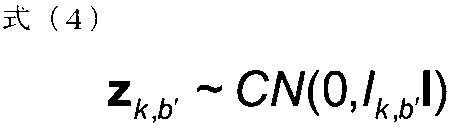
- Z k, b ′ is represented by the following formula (4).
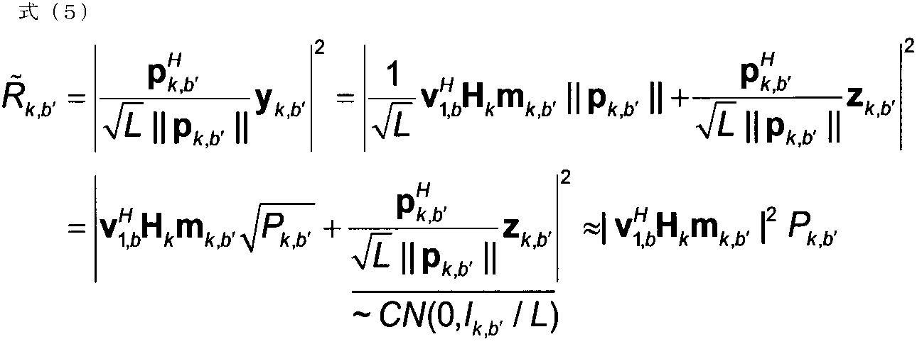
- the interference signal power R k, b ′ by the b′-th beam from the k-th radio base station BS is expressed by the following equation (5).
- the radio base station BS needs to know the radio resource (resource element) in which the estimation reference signal is arranged in the neighboring cells and the estimation reference signal sequence.
- the radio resource resource element
- a large error is included in the estimated value of the interference signal power R k, b ′ from neighboring cells at a distance.
- the noise power N 0 since interference from data signals in neighboring cells is included in the estimation reference signal, it is difficult to measure the noise power N 0 .
- FIG. 10 is an explanatory diagram of an arrangement example of estimation reference signals in the wireless communication method according to the second aspect.
- reference signals for estimation of all beams of all radio base stations BS1 to BS3 are mapped to the same resource element.
- reference signals for estimation of all beams of all radio base stations BS are code division multiplexed on the same resource element.
- code division multiplexing a CAZAC (Constant Amplitude Zero Auto-Correlation) sequence, a WALSH code, or the like may be used. Note that the arrangement shown in FIG. 10 is based on the assumption that all radio base stations BS1 to BS3 are synchronized (inter-cell synchronization).
- ⁇ q k, b ′, i ⁇ is independent.
- E i [q k, b ′, i ] 0.
- 2 P k, b ′ .
- q k, b ′ [q k, b ′, 1 ,..., Q k, b ′, F ] T.
- the relationship of following formula (7) is formed.
- estimation reference signals that are beam-formed using a beam-forming matrix M at timing T after timing T ⁇ and multiplexed on the same radio resource as shown in FIG.
- the user terminal UE estimates interference estimation information based on the estimation reference signal (performs channel estimation).
- the user terminal UE may estimate interference estimation information (for example, SINR) based on the estimation reference signal and the existing reference signal.
- the user terminal UE estimates the desired signal power based on the existing reference signal, and estimates the interference signal power based on the estimation reference signal described above. May be.
- the existing reference signal for example, CSI-RS (Channel State Information-Reference Signal) may be used.
- SINR 1 and b of the b-th beam from the first radio base station BS are expressed by Expression (9).
- the desired signal power of the existing reference signal for example, CSI-RS
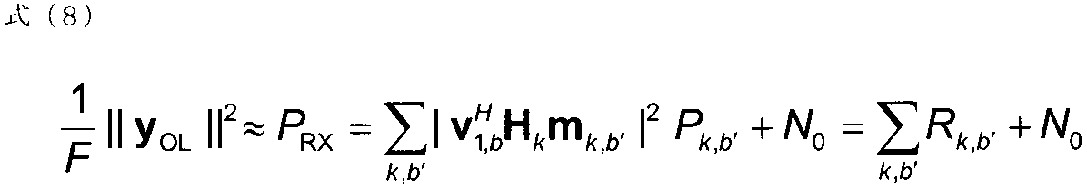
- the desired signal power of the existing reference signal is calculated from the sum of the total received power of the estimation reference signal multiplexed on the same resource element shown in Equation (8) and the noise power N 0. Is subtracted.
- the SINR can be estimated based on the estimation reference signal multiplexed on the same resource and the existing reference signal.
- the user terminal UE may estimate both the desired signal power and the interference signal power based on the estimation reference signal described above.
- the desired signal power estimated based on the estimation reference signal is expressed by Equation (10).
- Equation (11) assumes that the user terminal UE knows at least one of the reference signals q k, b ′ for estimating the b′-th beam from the k-th radio base station BS. It is. In such a case, a decorrelator is also possible.
- FIG. 11 is a flowchart illustrating a wireless communication method according to the second aspect. Below, it demonstrates centering around operation
- the estimation reference signal is transmitted after beam forming (precoding) by OL beam forming.
- the radio base station BS1 uses a beamforming matrix M 1 used for transmission of a downlink signal (for example, PDSCH) at a timing T (second timing) next to the timing T ⁇ (first timing).
- T (precoding matrix) is determined in advance.
- the beam forming matrix at the timing T may be determined in advance or may be random.
- the radio base station BS1 precodes estimation reference signals for the number of beams (streams and layers) at the timing T- ⁇ using the beamforming matrix M 1 (T) at the next timing T. To send. Similarly, each radio base station BS in the neighboring cell also precodes and transmits estimation reference signals for the number of beams using the beamforming matrix M (T) at the next timing T.
- step S102 the radio base station BS1 maps the estimation reference signal for all beams from the own station to the same radio resource as the estimation reference signal for all beams in the neighboring cells. .
- the estimation accuracy of the interference amount can be improved as compared with the case where the estimation reference signal from the own station is orthogonally mapped within the cell and does not overlap between the cells.
- the user terminal UE performs interference estimation (channel estimation) on each beam from the radio base station BS1, and feeds back interference estimation information (for example, SINR) of each beam (stream, layer) to the radio base station BS1.
- SINR interference estimation information
- the user terminal UE may estimate the SINR based on the existing reference signal (for example, CSI-RS) and the above-described estimation reference signal.
- user terminal UE may estimate SINR based on the above-mentioned estimation reference signal, without using the existing reference signal, as shown in formula (11).
- the radio base station BS1 schedules the user terminal UE appropriate for each beam (stream, layer) based on the interference estimation information of each beam fed back from the user terminal UE. For example, the radio base station BS1 selects the user terminal UE having the highest SINR of each beam and assigns it to each beam.
- step S105 the radio base station BS1 precodes and transmits a downlink signal (for example, PDSCH) at the current timing T based on the scheduling result in step S104.
- a downlink signal for example, PDSCH
- the downlink signal may be transmitted based on the transmission mode set in the user terminal UE in the radio communication method according to the first aspect. Moreover, this transmission mode may be changed semi-statically based on the interference estimation information fed back in step S103. Also, a plurality of transmission methods supported in the transmission mode may be dynamically changed based on the interference estimation information fed back in step S103.
- the beamforming matrices M 1 (T) and M 2 (T) at the timing T at which the downlink signal is transmitted based on the interference estimation information by the estimation reference signal are used. Therefore, the accuracy of the interference estimation information can be improved because the estimation reference signal is transmitted by being multiplexed with the same radio resource as the estimation reference signal for all the beams in the neighboring cells.
- the radio communication method is a radio communication method in a radio communication system in which the radio base station BS transmits a downlink signal to the user terminal UE, and in the radio base station BS, interference estimation information in the user terminal UE Mapping the estimation reference signal used for the estimation to the same radio resource as the neighboring radio base station BS, and instead of the first timing beamforming matrix for transmitting the estimation reference signal, the estimation Transmitting a reference signal for estimation using a beamforming matrix at a second timing at which a downlink signal is transmitted based on interference estimation information by the reference signal for use.
- the wireless communication system 1 includes a wireless base station 10 (10A, 10B) and a plurality of user terminals 20 (20A, 20B).
- the radio base station 10 is connected to the upper station apparatus 30, and the upper station apparatus 30 is connected to the core network 40.
- Each user terminal 20 can communicate with the radio base station 10 in the cells C1 and C2.
- the user terminal 20 may be a mobile terminal or a fixed terminal.
- the upper station device 30 includes, for example, an access gateway device, a radio network controller (RNC), a mobility management entity (MME), and the like, but is not limited thereto.
- RNC radio network controller
- MME mobility management entity
- OFDMA Orthogonal Frequency Division Multiple Access
- SC-FDMA Single Carrier Frequency Division Multiple Access
- OFDMA is a multi-carrier transmission scheme that performs communication by dividing a frequency band into a plurality of narrow frequency bands (subcarriers) and mapping data to each subcarrier.
- SC-FDMA is a single carrier transmission method that reduces interference between terminals by dividing a system band into bands each consisting of one or continuous resource blocks for each terminal, and a plurality of terminals using different bands.
- NOMA is applied to the downlink of the wireless communication system 1 as necessary.
- the downlink communication channel has PDSCH (Physical Downlink Shared CHannel) shared by each user terminal 20 and downlink L1 / L2 control channels (PDCCH, PCFICH, PHICH, EPDCCH).
- PDSCH Physical Downlink Shared CHannel
- PDSCH and PUSCH scheduling information, etc. are transmitted by PDCCH (Physical Downlink Control CHannel).
- the number of OFDM symbols used for the PDCCH is transmitted by PCFICH (Physical Control Format Indicator CHannel).
- the HARQ ACK / NACK for PUSCH is transmitted by PHICH (Physical Hybrid-ARQ Indicator CHannel).
- the uplink communication channel has PUSCH (Physical Uplink Shared CHannel) as an uplink shared channel shared by each user terminal 20 and PUCCH (Physical Uplink Control CHannel) as an uplink control channel.
- PUSCH Physical Uplink Shared CHannel
- PUCCH Physical Uplink Control CHannel
- User data and higher control information are transmitted by this PUSCH.
- downlink interference estimation information CQI, SINR, etc.
- delivery confirmation information ACK / NACK / DTX
- ACK / NACK / DTX delivery confirmation information
- FIG. 13 is a schematic configuration diagram of the radio base station according to the present embodiment.
- the radio base station 10 includes a plurality of transmission / reception antennas 101 for beam forming, an amplifier unit 102, a transmission / reception unit 103, a baseband signal processing unit 104, a call processing unit 105, and a transmission path interface 106. Yes.
- User data transmitted from the radio base station 10 to the user terminal 20 in the downlink is input from the higher station apparatus 30 to the baseband signal processing unit 104 via the transmission path interface 106.
- the baseband signal processing unit 104 performs PDCP layer processing, user data division / combination, RLC (Radio Link Control) retransmission control transmission processing such as RLC layer transmission processing, MAC ( Medium Access Control (retransmission control), for example, HARQ transmission processing, scheduling, transmission format selection, channel coding, inverse fast Fourier transform (IFFT) processing, precoding processing, etc. Forward.
- RLC Radio Link Control
- MAC Medium Access Control (retransmission control)
- HARQ transmission processing scheduling, transmission format selection, channel coding, inverse fast Fourier transform (IFFT) processing, precoding processing, etc. Forward.
- transmission processing such as channel coding and IFFT processing is performed on the downlink control information, and the transmission information is transferred to each transmission / reception section 103.
- the baseband signal processing unit 104 notifies the control information for communication in the serving cell to the user terminal 20 through the broadcast channel.
- the information for communication in the serving cell includes, for example, the system bandwidth in the uplink or the downlink.
- Each transmission / reception unit 103 converts the baseband signal output by precoding from the baseband signal processing unit 104 for each antenna to a radio frequency band.
- the amplifier unit 102 amplifies the frequency-converted radio frequency signal and transmits it from the transmission / reception antenna 101.
- each transmitting / receiving antenna 101 receives data transmitted from the user terminal 20 to the radio base station 10 via the uplink.
- the amplifier unit 102 amplifies the radio frequency signal input from each transmission / reception antenna 101 and sends the amplified signal to each transmission / reception unit 103.
- the amplified radio frequency signal is converted into a baseband signal by each transmitting / receiving unit 103 and input to the baseband signal processing unit 104.
- the baseband signal processing unit 104 performs fast Fourier transform (FFT: Fast Fourier Transform) processing, inverse discrete Fourier transform (IDFT: Inverse Discrete Fourier Transform) processing, error on user data included in the input baseband signal. Correction decoding, MAC retransmission control reception processing, RLC layer, PDCP layer reception processing, and the like are performed and transferred to the upper station apparatus 30 via the transmission path interface 106.
- the call processing unit 105 performs call processing such as communication channel setting and release, state management of the radio base station 10, and radio resource management.
- FIG. 14 is a schematic configuration diagram of a user terminal according to the present embodiment.
- the user terminal 20 includes a plurality of transmission / reception antennas 201, an amplifier unit 202, a transmission / reception unit 203, a baseband signal processing unit 204, and an application unit 205.
- Downlink data is received by a plurality of transmission / reception antennas 201 and input to an amplifier unit 202.
- the amplifier unit 202 amplifies the radio frequency signal input from each transmission / reception antenna 201 and sends the amplified signal to each transmission / reception unit 203.
- the amplified radio frequency signal is converted into a baseband signal by each transmission / reception unit 203 and input to the baseband signal processing unit 204.
- the baseband signal processing unit 204 performs FFT processing, error correction decoding, retransmission control reception processing, and the like on the input baseband signal.
- User data included in the downlink data is transferred to the application unit 205.
- the application unit 205 performs processing related to layers higher than the physical layer and the MAC layer.
- broadcast information included in downlink data is also transferred to the application unit 205.
- uplink user data is input from the application unit 205 to the baseband signal processing unit 204.
- the baseband signal processing unit 204 performs retransmission control transmission processing, channel coding, precoding, Discrete Fourier Transform (DFT) processing, IFFT processing, and the like on the input user data, and performs each transmission / reception
- the data is transferred to the unit 203.
- Each transmitting / receiving unit 203 converts the baseband signal output from the baseband signal processing unit 204 into a radio frequency band.
- the amplifier unit 202 amplifies the frequency-converted radio frequency signal and transmits it from the transmission / reception antenna 201.
- FIG. 15 is a functional configuration diagram of the radio base station and the user terminal according to the present embodiment.
- the functional configuration shown in FIG. 15 includes the baseband signal processing units 104 and 204. Further, FIG. 15 shows only a part of the configuration, but it is assumed that the radio base station 10 and the user terminal 20 have a necessary configuration without a shortage.
- the radio base station 10 includes a scheduling unit 111, a transmission mode setting unit 112, a downlink control information (DCI) generation unit 113, a downlink data generation unit 114, a reference signal generation unit 115, and a precoding unit 116. It has.
- DCI downlink control information
- the scheduling unit 111 performs scheduling based on interference estimation information from the user terminal 20.
- the interference estimation information may be any information indicating the amount of interference and channel quality in the user terminal UE, such as received SINR, path loss, CQI, SNR, and CSI.
- the scheduling unit 111 determines the user terminal 20 to be spatially multiplexed or non-orthogonally multiplexed based on the interference estimation information and allocates radio resources.
- the scheduling part 111 may determine the transmission power of the user terminal 20 to be non-orthogonal multiplexed.
- the transmission mode setting unit 112 (setting unit) is one of a plurality of transmission modes including a first transmission mode in which a plurality of transmission methods are grouped and a second transmission mode in which a plurality of transmission methods are grouped. Is configured for the user terminal 20. Moreover, the transmission mode setting part 112 switches the transmission mode set with respect to the said user terminal using higher layer signaling (for example, RRC signaling). Further, the transmission mode setting unit 112 uses lower layer signaling (for example, MAC signaling) or DCI rather than upper layer signaling, and is applied to a downlink signal among a plurality of transmission methods grouped in the transmission mode. Switch law.
- grouping of transmission methods in the first transmission mode and the second transmission mode is performed depending on whether the transmission method requires feedback information from the user terminal UE (whether it is a closed loop or an open loop). It may be performed depending on whether it is MIMO or transmission diversity. Further, overlapping transmission methods may be included in both the first transmission mode and the second transmission mode.
- the DCI generating unit 113 generates downlink control information (DCI) transmitted by PDCCH or EPDCCH and performs transmission processing (for example, encoding, modulation, mapping to radio resources, etc.).
- the DCI includes PDSCH / PUSCH allocation information and the like.
- the DCI includes various types of information necessary for receiving a non-orthogonal multiplexed signal.
- the DCI may also include transmission method switching information in a transmission mode configured in the user terminal 20.
- the downlink data generation unit 114 generates downlink user data and higher layer control information transmitted on the PDSCH, and performs transmission processing (eg, encoding, modulation, radio resource) based on the transmission mode set by the transmission mode setting unit 112. Mapping).
- the higher layer control information includes control information transmitted by higher layer signaling (for example, RRC signaling) or lower layer signaling (for example, MAC signaling) than the higher layer signaling.
- the higher layer control information may include transmission mode setting information and switching information for the user terminal UE.
- the control information by MAC signaling may include the above-described transmission method switching information.
- the reference signal generation unit 115 generates reference signals such as CRS (Cell-specific Reference Signal), CSI-RS, DM-RS (FIG. 6), estimation reference signals (FIG. 10), and performs transmission processing (for example, code , Modulation, mapping to radio resources, etc.).
- CRS Cell-specific Reference Signal
- CSI-RS Cell-specific Reference Signal
- DM-RS DM-RS
- estimation reference signals FOG. 10
- transmission processing for example, code , Modulation, mapping to radio resources, etc.
- the DM-RS used as the demodulation reference signal may be common among the user terminals 20.
- the estimation reference signal is a reference signal used for estimation of interference estimation information in the user terminal 20 and is the same between the surrounding radio base station 10 and all beams (streams and layers). May be mapped to other radio resources (resource elements).
- the precoding unit 116 precodes (beam-forms) and transmits the downlink signal output from the downlink data generation unit 114 and the reference signal output from the reference signal generation unit 115. Specifically, the precoding unit 116 precodes and transmits DM-RSs using a beamforming matrix corresponding to the downlink signal.
- the precoding unit 116 performs downlink based on interference estimation information by the reference signal instead of the beamforming matrix M (T ⁇ ) at the timing T ⁇ (first timing) at which the estimation reference signal is transmitted.
- the estimation reference signal is transmitted using the beamforming matrix M (T) at the timing at which the signal is transmitted (second timing).
- the user terminal 20 includes an interference estimation unit 211, a DCI reception processing unit 212, a downlink data reception processing unit 213, and a transmission mode setting unit 214.
- the interference estimation unit 211 estimates interference estimation information (performs channel estimation) based on the estimation reference signal from the radio base station 10.
- the interference estimation unit 211 may estimate the interference estimation information (for example, SINR) based on the estimation reference signal and the existing reference signal (for example, CSI-RS) as shown in Expression (9). Good.
- the interference estimation unit 211 may estimate the interference estimation information using the estimation reference signal without using the existing reference signal (for example, CSI-RS), as shown in Expression (10). .
- the DCI reception processing unit 212 performs blind decoding on the DCI from the radio base station 10 and performs reception processing (for example, demapping, demodulation, decoding, etc.).
- DCI may include transmission method switching information within the transmission mode set in the user terminal 20.
- the downlink data reception processing unit 213 performs reception processing (for example, IRC, SIC, demapping, demodulation, decoding, etc.) of downlink data (including higher layer control information) from the radio base station 10. Interference beams are removed by linear filtering such as IRC, and a beam for the terminal is extracted. Further, the downlink signal (interference signal) for the other user terminal 20 multiplexed on the same beam is removed by the SIC, and the downlink signal for the own terminal is extracted.
- reception processing for example, IRC, SIC, demapping, demodulation, decoding, etc.
- the downlink data reception processing unit 213 may demodulate the downlink data based on the DM-RS common to the user terminals 20 and the transmission power ratio between the user terminals 20. Further, as described above, the upper layer control information may include transmission mode setting information or switching information set in the user terminal 20.
- the transmission mode setting unit 214 sets the transmission mode of the user terminal UE based on the above-described transmission mode setting information or switching information, and performs downlink data reception processing so as to perform downlink data reception processing based on the transmission mode.
- the unit 213 is controlled.
- the transmission mode setting unit 214 performs downlink data reception processing according to the transmission method based on the transmission method switching information within the transmission mode set in the user terminal 20. May be controlled.
- a transmission mode corresponding to NOMA / MU-MIMO is defined.
- the frequency utilization efficiency can be improved. Since a first transmission mode in which a plurality of transmission methods including NOMA / MU-MIMO are grouped and a second transmission mode in which a plurality of transmission methods including NOMA / open loop transmission diversity are grouped are defined, the control load It is possible to support various transmission methods without increasing the number (first mode).
Abstract
非直交多重アクセス(NOMA)を利用可能な無線通信システムにおいて、周波数利用効率を向上させること。無線基地局が、非直交多重アクセス(NOMA)とマルチユーザ多入力多出力(MU-MIMO)とを用いた送信法を含む複数の送信法がグループ化される第1送信モードと、前記NOMAと開ループ送信ダイバーシチとを用いた送信法を含む複数の送信法がグループ化される第2送信モードと、を含む複数の送信モードの一つを、前記ユーザ端末に対して設定する工程と、前記無線基地局が、設定された送信モードに基づいて、前記ユーザ端末に対する下り信号を送信する工程と、を有する。
Description
本発明は、非直交多重アクセス(NOMA)を利用可能な無線通信システムにおいて、無線基地局、ユーザ端末及び無線通信方法に関する。
従来、無線通信システムでは、様々な無線アクセス方式が用いられている。例えば、W-CDMA(Wideband Code Division Multiple Access)とも呼ばれるUMTS(Universal Mobile Telecommunications System)では、符号分割多重アクセス(CDMA:Code Division Multiple Access)が用いられる。また、LTE(Long Term Evolution)では、直交周波数分割多重アクセス(OFDMA:Orthogonal Frequency Division Multiple Access)が用いられる(例えば、非特許文献1)。
3GPP TR 25.913"Requirements for Evolved UTRA and Evolved UTRAN"
FRA(Future Radio Access)などと呼ばれる将来の無線通信システムでは、受信側での干渉除去(Interference Cancellation)を前提する非直交多重アクセス(NOMA:Non-Orthogonal Multiple Access)を用いた無線アクセス方式が検討されている。
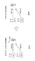
かかる無線アクセス方式では、例えば、図1に示すように、直交周波数分割多重アクセス(OFDMA)によって割り当てられる同一の無線リソースに対して、受信SINRやパスロスなどが異なるユーザ端末の信号が重畳され、それぞれ、異なる送信電力で送信される。受信側では、他のユーザ端末の信号をキャンセルすることで、所望のユーザ端末の信号が抽出される。
NOMAを用いた無線アクセス方式では、同一の無線リソースに対して複数のユーザ端末を多重できるので、周波数利用効率の向上が見込まれる。一方、将来の無線通信システムでは、飛躍的なトラヒック増大が見込まれるため、更なる周波数利用効率の向上が望まれる。
本発明はかかる点に鑑みてなされたものであり、非直交多重アクセス(NOMA)を利用可能な無線通信システムにおいて、周波数利用効率を向上可能な無線基地局、ユーザ端末及び無線通信方法を提供することを目的とする。
本発明の無線通信方法は、無線基地局がユーザ端末に対する下り信号を送信する無線通信システムにおける無線通信方法であって、前記無線基地局が、非直交多重アクセス(NOMA)とマルチユーザ多入力多出力(MU-MIMO)とを用いた送信法を含む複数の送信法がグループ化される第1送信モードと、前記NOMAと開ループ送信ダイバーシチとを用いた送信法を含む複数の送信法がグループ化される第2送信モードと、を含む複数の送信モードの一つを、前記ユーザ端末に対して設定する工程と、前記無線基地局が、設定された送信モードに基づいて、前記下り信号を送信する工程と、を有する。
本発明によれば、非直交多重アクセス(NOMA)を利用可能な無線通信システムにおいて、周波数利用効率を向上させることができる。
図2は、下りリンクにおける非直交多重アクセス(NOMA)の説明図である。図2では、無線基地局BSによって形成されるセルの中央部(以下、セル中央部という)にユーザ端末UE1が位置し、当該セルの端部(以下、セル端部という)にユーザ端末UE2が位置する場合が示される。セル内のパスロスは、セル中央部からセル端部に向かうにつれて増加する。このため、図2に示すように、パスロスが大きいセル端部に位置するユーザ端末UE2の受信SINR(Received Signal to Interference plus Noise Ratio)は、パスロスが小さいセル中央部に位置するユーザ端末UE1の受信SINRよりも低くなる。
NOMAでは、受信SINRなどの干渉推定情報(後述)の相違に応じて送信電力を異ならせることで、同一の無線リソースに対して複数のユーザ端末UEを多重する。例えば、図2では、受信SINRが異なるユーザ端末UE1及びUE2に対する下り信号が同一の無線リソースに多重される。また、受信SINRが高いユーザ端末UE1に対する下り信号が相対的に小さい送信電力で送信され、受信SINRが低いユーザ端末UE2に対する下り信号が相対的に大きい送信電力で送信される。
また、NOMAでは、SIC(Successive Interference Cancellation)により受信信号から干渉信号を除去することで、自端末に対する下り信号が抽出される。具体的には、自端末より受信SINRが低い他のユーザ端末に対する下り信号を除去することで、自端末に対する下り信号が抽出される。
例えば、図2において、ユーザ端末UE2の受信SINRはユーザ端末UE1よりも低いので、ユーザ端末UE2に対する下り信号は、ユーザ端末UE1に対する下り信号より大きい送信電力で送信される。このため、ユーザ端末UE1は、ユーザ端末UE2に対する下り信号を干渉信号として受信してしまうが、当該干渉信号は、SICにより適切に除去される。この結果、ユーザ端末UE1は、自端末に対する下り信号を抽出して適切に復号できる。
一方、ユーザ端末UE1の受信SINRはユーザ端末UE2よりも高いので、ユーザ端末UE1に対する下り信号は、ユーザ端末UE2に対する下り信号より小さい送信電力で送信される。このため、ユーザ端末UE2は、ユーザ端末UE1に対する下り信号による干渉を無視でき、SICによる干渉除去を行う必要はない。
このように、下りリンクにおいてNOMAを適用する場合、同一の無線リソースに対して、受信SINRが異なる複数のユーザ端末UE1及びUE2を多重できるので、周波数利用効率を向上させることができる。一方、将来の無線通信システムでは、飛躍的なトラヒック増大が見込まれるため、更なる周波数利用効率の改善が望まれる。そこで、下りリンクにおいてNOMAに加えて多入力多出力(MIMO:Multiple-Input and Multiple-Output)を適用することが検討されている。
図3は、下りリンクにおけるNOMAとマルチユーザ多入力多出力(MU-MIMO)とを用いた送信法(以下、NOMA/MU-MIMO)の説明図である。図3では、ユーザ端末UE1及びUE2は、無線基地局BSから同一方向で受信SINR(ビームレベルSINR)が異なる位置に位置する。同様に、ユーザ端末UE3及びUE4は、無線基地局BSから同一方向で受信SINRが異なる位置に位置する。
NOMA/MU-MIMOでは、異なる指向性を有する複数のビームにより複数のユーザ端末UEに対する下り信号がそれぞれ送信される。また、各ビームにおいて、受信SINRが異なる複数のユーザ端末UEに対する下り信号が送信される。一方、受信側では、IRC(Interference Rejection Combining)により干渉ビームを抑制することで、自端末に対するビームが抽出される。また、抽出されたビームからSICにより干渉信号を除去することで、自端末に対する下り信号が抽出される。
例えば、図3では、無線基地局BSは、ビームB1により、ユーザ端末UE1及びUE2に対する下り信号を送信する。ユーザ端末UE2の受信SINRはユーザ端末UE1よりも低いので、ユーザ端末UE2に対する下り信号は、ユーザ端末UE1に対する下り信号よりも大きい送信電力で送信される。また、無線基地局BSは、ビームB2により、ユーザ端末UE3及びUE4に対する下り信号を送信する。ユーザ端末UE4の受信SINRはユーザ端末UE3よりも低いので、ユーザ端末UE4に対する下り信号は、ユーザ端末UE3に対する下り信号よりも大きい送信電力で送信される。
図3において、ユーザ端末UE1及びUE2は、IRCにより干渉ビーム(ここでは、ビームB2)を抑制して、自端末に対するビームB1を抽出する。また、ユーザ端末UE1は、SICによりユーザ端末UE2に対する下り信号を除去して、ユーザ端末UE1に対する下り信号を抽出して復号する。なお、ユーザ端末UE2では、ユーザ端末UE1に対する下り信号による干渉を無視できるため、SICは省略される。
同様に、ユーザ端末UE3及びUE4は、IRCにより干渉ビーム(ここでは、ビームB1)を抑制することで、自端末に対するビームB2を抽出する。また、ユーザ端末UE3は、SICによりユーザ端末UE4に対する下り信号を除去して、ユーザ端末UE3に対する下り信号を抽出して復号する。なお、ユーザ端末UE4では、ユーザ端末UE3に対する下り信号による干渉を無視できるため、SICは省略される。
このように、NOMA/MU-MIMOでは、無線基地局BSからの複数のビームに対してそれぞれ異なるユーザ端末UEが空間分割多重(SDM)されるとともに、同一ビーム内に受信SINRが異なるユーザ端末UEが非直交多重(NOM)される。このため、同一の無線リソースに対してより多くのユーザ端末UEを多重可能となり、周波数利用効率が向上する。
以上のように、下りリンクにおいてNOMA/MU-MIMOを適用する場合、周波数利用効率の更なる向上が見込まれる。一方で、NOMA/MU-MIMOを適用する無線通信システムにおいても、種々の条件に応じて、NOMA/MU-MIMO以外の送信法をサポートすることが望まれる。
図4及び図5を参照し、NOMA/MU-MIMOが適用される無線通信システムにおいて、サポートすべき種々の送信法を説明する。なお、図4及び図5では、無線基地局BSが2送信アンテナを備える場合を示すが、送信アンテナ数はこれに限られない。
図4Aでは、NOMA/MU-MIMOが示される。上述のように、NOMA/MU-MIMOでは、無線基地局BSから送信される複数のビームに対して、異なるユーザ端末UEに対する下り信号が空間多重される。また、同一のビーム内において、複数のユーザ端末UEに対する下り信号が非直交多重される。NOMA/MU-MIMOでは、周波数利用効率が向上する。
また、図4Bでは、NOMAとシングルユーザ多入力多出力(SU-MIMO)とを用いた送信法(以下、NOMA/SU-MIMOと略する)が示される。NOMA/SU-MIMOでは、図4Bに示すように、無線基地局BSから送信される複数のビームに対して、同一のユーザ端末UEに対する下り信号が空間多重される。また、同一のビーム内において、複数のユーザ端末UEに対する下り信号が非直交多重される。NOMA/SU-MIMOでは、複数のビーム(レイヤ)により同一のユーザ端末UEに対する下り信号が送信されるので、ピークレートが向上する。
また、図4Cでは、NOMAと送信ダイバーシチとを用いた送信法(以下、NOMA/送信ダイバーシチと略する)が示される。NOMA/送信ダイバーシチでは、図4Bに示すように、複数のビームを用いずに、複数のユーザ端末UEに対する下り信号が非直交多重されて送信される。具体的には、STBC(Space-Time Block Coding)やSTTC(Space-Time Trellis Coding)を用いて、複数のユーザ端末UEに対する下り信号が時空間符号化され、異なる送信電力で送信される。NOMA/送信ダイバーシチは、MIMOによるプリコーディングゲインが小さい環境下において有効である。
なお、送信ダイバーシチは、ユーザ端末UEからのフィードバック情報を用いる閉ループ(CL)送信ダイバーシチと、ユーザ端末UEからのフィードバック情報を用いない開ループ(OL)送信ダイバーシチとを含んでもよい。
また、非直交多重の対象となる複数のユーザ端末UEが存在しない場合を想定し、図5に示すように、NOMAを前提としない送信法をサポートすることも望まれる。
図5Aでは、NOMAを用いずにSU-MIMOを用いた送信法(以下、SU-MIMOと略する)が示される。SU-MIMOでは、図5Aに示すように、無線基地局BSから送信される複数のビームに対して、単一のユーザ端末UEに対する下り信号が空間多重される。SU-MIMOは、NOMAの対象となる他のユーザ端末UEが存在しない場合に、有効である。
図5Bでは、閉ループ(CL)送信ダイバーシチ又は開ループ(OL)送信ダイバーシチを用いた送信法が示される。CL送信ダイバーシチ又はOL送信ダイバーシチでは、図5Bに示すように、STBCやSTTCを用いて単一のユーザ端末UEに対する下り信号が時空間符号化されて送信される。CL送信ダイバーシチやOL送信ダイバーシチは、NOMAの対象となる他のユーザ端末UEが存在せず、MIMOによるプリコーディングゲインが小さい環境下において有効である。
以上のように、下りリンクにおいてNOMA/MU-MIMOが適用される無線通信システムでは、NOMAを前提する送信法(例えば、NOMA/MU-MIMO、NOMA/SU-MIMO、NOMA/CL送信ダイバーシチ、NOMA/OL送信ダイバーシチ)や、NOMAを前提としない送信法(例えば、SU-MIMO、CL送信ダイバーシチ、OL送信ダイバーシチ)など、多様な送信法をサポートすることが望まれる。
しかしながら、下りリンクにおいてNOMA/MU-MIMOが適用される無線通信システムにおいて、多様な送信法を動的にサポートしようとすると、制御負荷が増大する恐れがある。そこで、本発明者らは、複数の送信法をグループ化した送信モードを規定することで、制御負荷を増大せずに、多様な送信法をサポートするという着想を得て、本発明に至った。
以下、本発明に係る無線通信方法を詳細に説明する。なお、以下の本発明の第1態様及び第2態様に係る無線通信方法は、単独で用いられてもよいし、適宜組み合わせて用いられてもよい。また、以下において、干渉推定情報とは、受信SINR、パスロス、CQI(Channel Quality Indicator)、SNR、CSI(Channel State Information)など、ユーザ端末UEにおける干渉量やチャネル品質を示すどのような情報であってもよい。
(第1態様)
第1態様に係る無線通信方法では、無線基地局BSは、NOMA/MU-MIMOを含む複数の送信法がグループ化される第1送信モードと、NOMA/OL送信ダイバーシチを含む複数の送信法がグループ化される第2送信モードと、を含む複数の送信モードの一つをユーザ端末UEに対して設定(configure)する。無線基地局BSは、設定された送信モードに基づいて、下り信号を送信する。ユーザ端末UEは、設定された送信モードを示す送信モード情報に基づいて、下り信号の受信処理(例えば、復調、復号など)を行う。
第1態様に係る無線通信方法では、無線基地局BSは、NOMA/MU-MIMOを含む複数の送信法がグループ化される第1送信モードと、NOMA/OL送信ダイバーシチを含む複数の送信法がグループ化される第2送信モードと、を含む複数の送信モードの一つをユーザ端末UEに対して設定(configure)する。無線基地局BSは、設定された送信モードに基づいて、下り信号を送信する。ユーザ端末UEは、設定された送信モードを示す送信モード情報に基づいて、下り信号の受信処理(例えば、復調、復号など)を行う。
ここで、第1送信モードでグループ化される複数の送信法には、上述のNOMA/MIMOに加えて、CL送信ダイバーシチ(NOMAを用いず、シングルユーザCL送信ダイバーシチと呼ばれてもよい)、SU-MIMO(NOMAを用いない)、NOMA/CL送信ダイバーシチ、NOMA/SU-MIMOの少なくとも一つが含まれてもよい。
また、第2送信モードでグループ化される複数の送信法には、上述のNOMA/OL送信ダイバーシチに加えて、OL送信ダイバーシチ(NOMA用いず、シングルユーザOL送信ダイバーシチと呼ばれてもよい)、SU-MIMO(NOMAを用いない)、NOMA/OL送信ダイバーシチ、NOMA/SU-MIMOの少なくとも一つが含まれてもよい。
なお、第1送信モード及び第2送信モードでそれぞれグループ化される送信法は、上記に限られない。また、第1送信モード及び第2送信モードの区別も上記に限られるものではない。例えば、ユーザ端末UEからのフィードバック情報を要する送信法であるか否かによって、第1送信モード及び第2送信モードの送信法がグループ化されてもよい。また、MIMOであるか、送信ダイバーシチであるかによって、第1送信モード及び第2送信モードの送信法がグループ化されてもよい。
第1態様に係る無線通信方法において、無線基地局BSは、ユーザ端末UEからの干渉推定情報に基づいて、複数の送信モードの一つをユーザ端末UEに対して設定してもよい。また、無線基地局BSは、ユーザ端末UEからの干渉推定情報に基づいて、ユーザ端末UEに設定される送信モードを切り替えてもよい。なお、送信モードの設定及び切り替えは、上位レイヤシグナリング(例えば、RRCシグナリング)を用いて行われてもよい。これにより、送信モードを準静的(Semi-static)に切り替え可能となる。
また、無線基地局BSは、ユーザ端末UEからの干渉推定情報に基づいて、設定された送信モードでグループ化される複数の送信法のうち、ユーザ端末UEに対する下り信号に適用される送信法を設定してもよい。また、無線基地局BSは、ユーザ端末UEからの干渉推定情報に基づいて、設定された送信モードにおいて、ユーザ端末UEに対する下り信号に適用される送信法を切り替えてもよい。なお、送信法の設定及び切り替えは、上位レイヤシグナリングよりも下位レイヤのシグナリング(例えば、MACシグナリング)や、L1/L2制御チャネル(例えば、下り制御チャネル(PDCCH:Physical Downlink Control Channel))を用いて行われてもよい。これにより、送信モード内の送信法を動的(Dynamic)に切り替え可能となる。
また、第1態様に係る無線通信方法において、上述の第1送信モード及び第2送信モードに基づいて送信される下り信号は、下り共有チャネル(PDSCH:Physical Downlink Shared Channel)であってもよい。
ここで、PDSCHの送信モードとしては、単一アンテナポートをサポートする送信モード1、送信ダイバーシチをサポートする送信モード2、開ループ空間多重をサポートする送信モード3、閉ループ空間多重をサポートする送信モード4、MU-MIMOをサポートする送信モード5、単一レイヤの閉ループ空間多重をサポートする送信モード6、ユーザ端末UE固有の参照信号(例えば、DM-RS:Demodulation Reference Signal)を用いたレイヤ送信をサポートする送信モード7-9、CoMP(Coordinated Multipoint Transmission)をサポートする送信モード10などが規定されている。
そこで、PDSCHの送信モードとして、上述の第1送信モード及び第2送信モードを追加して、NOMA/MIMOによるPDSCHの送信を実現してもよい。かかる場合、例えば、上述の第1送信モード、第2送信モードが、それぞれ送信モード11、12として規定されてもよい。
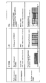
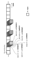
また、第1態様に係る無線通信方法において、第1送信モード及び第2送信モードでグループ化される各送信法では、ユーザ端末UE間で共通又は/及びレイヤ(ビーム)間で直交の参照信号が無線基地局BSから送信されてもよい。図6を参照し、各送信法で送信される下り信号の復調に用いられる参照信号(以下、復調用参照信号という)を説明する。なお、図6では、横軸は無線リソース(時間、周波数)を示し、縦軸は送信電力を示す。また、図6では、復調用参照信号が、連続する2リソースエレメントに配置されるが、これに限られない。
図6Aに示すように、1送信アンテナ(1Tx)によるNOMAを用いた送信法では、各ユーザ端末UE(ここでは、ユーザ端末UE1-UE3)に対する下り信号は、同じ無線リソースにおいて異なる送信電力で送信される。この場合、復調用参照信号として、各ユーザ端末UEに共通のDM-RS(Demodulation Reference Signal)を用いることができる。
また、図6Bに示すように、複数の送信アンテナ(ここでは、アンテナTx1,Tx2)によるSU-MIMOでは、単一のユーザ端末UE(ここでは、ユーザ端末UE1)に対する複数(2)レイヤの下り信号が同じ無線リソースに多重される。この場合、復調用参照信号として、例えば、レイヤ間で直交するDM-RSを用いることができる。
また、図6Cに示すように、複数の送信アンテナ(ここでは、アンテナTx1,Tx2)によるNOMA/SU-MIMOでは、各ユーザ端末UE(ここでは、ユーザ端末UE1-UE3)に対する複数(2)レイヤの下り信号が同じ無線リソースに多重される。ここで、ユーザ端末UEに対する下り信号は、異なる送信電力で送信される。この場合、復調用参照信号として、例えば、同一レイヤ内のユーザ端末UE間で共通し、レイヤ間では直交するDM-RSを用いることができる。
また、図6Dに示すように、複数の送信アンテナ(ここでは、送信アンテナTx1,Tx2)によるNOMA/MU-MIMOでは、各ユーザ端末UE(ここでは、ユーザ端末UE1-6)に対する下り信号が同じ無線リソースに多重される。同一レイヤ(ビーム)内では、各ユーザ端末UEに対する下り信号が異なる送信電力で送信される。この場合、復調用参照信号として、例えば、同一レイヤ(ビーム)内のユーザ端末UE間で共通し、レイヤ(ビーム)間で直交するDM-RSを用いることができる。
このように、ユーザ端末UE間で共通の復調用参照信号が用いられる場合、各ユーザ端末UEに対する下り信号の送信電力比が、無線基地局BSから通知されてもよい。これにより、共通の復調用参照信号が用いられる場合であっても、各ユーザ端末UEが、自端末に対する下り信号を適切に復調できる。なお、図6では、ユーザ端末UE間で共通の復調用参照信号を用いる場合を示したが、ユーザ端末UE固有の復調用参照信号が用いられてもよい。
以上の第1態様に係る無線通信方法によれば、非直交多重アクセス(NOMA)を利用可能な無線通信システムにおいて、NOMA/MU-MIMOに対応した送信モードが規定されるので、周波数利用効率を向上させることができる。NOMA/MU-MIMOを含む複数の送信法をグループ化した第1送信モードと、NOMA/開ループ送信ダイバーシチを含む複数の送信方法をグループ化した第2送信モードとが規定されるので、制御負荷を増大せずに、多様な送信法をサポートできる。
(第2態様)
第2態様に係る無線通信方法では、ユーザ端末UEにおける干渉の推定に用いられる参照信号(以下、推定用参照信号という)の送信方法を詳述する。
第2態様に係る無線通信方法では、ユーザ端末UEにおける干渉の推定に用いられる参照信号(以下、推定用参照信号という)の送信方法を詳述する。
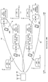
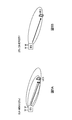
図7及び図8を参照し、閉ループ(CL)型ビームフォーミングと開ループ(OL)型ビームフォーミングについて説明する。図7は、CL型ビームフォーミングの説明図である。図8は、OL型ビームフォーミングの説明図である。なお、OL型ビームフォーミングは、ランダムビームフォーミング、Opportunisticビームフォーミングなどと呼ばれてもよい。
図7Aに示すように、CL型ビームフォーミングでは、タイミングT-Δにおいて、無線基地局BS1に接続するユーザ端末UEは、無線基地局BS2のビームフォーミング行列M2(T-Δ)に基づいて、無線基地局BS2から受ける干渉量を推定する。ユーザ端末UEは、推定された干渉量を示す干渉推定情報(例えば、SINR)と、当該干渉推定情報に対応するビームフォーミング行列M1(T)とを、無線基地局BS1にフィードバックする。
図7Bに示すように、タイミングTにおいて、無線基地局BS1は、ユーザ端末UEからフィードバックされたビームフォーミング行列M1(T)を、チャネル行列H1に乗算して送信する。ここで、タイミングTにおいて、ユーザ端末UEは、無線基地局BS2のビームフォーミング行列M2(T)を知らない。CL型ビームフォーミングでは、スケジューリング等の結果により、一般的に、タイミングT-Δ及びタイミングTにおいて、無線基地局BSで用いられるビームフォーミング行列M2(T-Δ)及びM2(T)は異なる。このため、タイミングT-Δ及びタイミングTにおける干渉量の推定結果には、誤差が生じる恐れがある。
一方、OL型ビームフォーミングでは、各無線基地局BSは、各時刻において、予め定められたビームフォーミング行列M又はランダムなビームフォーミング行列Mを、チャネル行列Hに乗算して送信する。すなわち、OL型ビームフォーミングでは、ユーザ端末UEからフィードバックされるビームフォーミング行列Mではなく、既知のビームフォーミング行列Mを用いる。
そこで、OL型ビームフォーミングでは、タイミングT-Δにおいて、タイミングT-Δよりも後のタイミングTにおけるビームフォーミング行列M(T)を用いることで、タイミングT-Δ及びタイミングTにおける干渉量の推定結果の誤差を軽減することが考えられる。
例えば、図8Aでは、タイミングT-Δにおいて、無線基地局BS1及びBS2は、それぞれ、タイミングTにおけるビームフォーミング行列M1(T)及びM2(T)を、チャネル行列H1及びH2に乗算して送信する。無線基地局BS1に接続するユーザ端末UEは、タイミングTにおけるビームフォーミング行列M2(T)に基づいて、無線基地局BS2から受ける干渉量を推定する。ユーザ端末UEは、推定された干渉量を示す干渉推定情報(例えば、SINR)を、無線基地局BS1にフィードバックする。
また、図8Bに示すように、無線基地局BS1は、ユーザ端末UEからフィードバックされた干渉推定情報に基づいて、スケジューリングを行う。このように、タイミングT-Δにおいて、タイミングT-Δより後のタイミングTのビームフォーミング行列M2(T)を用いることで、タイミングT-Δ及びタイミングTにおける干渉量の推定誤差を軽減できる。
以上のように、第2態様に係る無線通信方法では、各無線基地局BSは、推定用参照信号が送信されるタイミング(T-Δ)(第1タイミング)のビームフォーミング行列M1(T-Δ)及びM2(T-Δ)の代わりに、当該推定用参照信号による干渉推定情報に基づいて下り信号が送信されるタイミングT(第2タイミング)のビームフォーミング行列M1(T)及びM2(T)を用いて、当該推定用参照信号を送信する。これにより、ユーザ端末UEにおける干渉量の推定誤差を軽減できる。
ここで、ユーザ端末UEにおいて推定される干渉推定情報について詳述する。なお、以下では、干渉推定情報が、SINRであるものとするが、これに限られない。
無線基地局BS1に接続するユーザ端末UEの受信信号ベクトルyは、下記式(1)で表わされる。

ここで、H1m1,bは、1番目の無線基地局BS(ユーザ端末UEが接続する無線基地局BS1)からのb番目のビームによる受信信号(すなわち、希望信号)を示す。また、Hkmk,bは、k番目の無線基地局BSからのb番目のビームによる受信信号(すなわち、干渉信号)を示す。また、Wは、雑音を示す。また、mk,bは、k番目の無線基地局BSからのb番目のビームのビームフォーミング行列である。
また、1番目の無線基地局BSからのb番目のビーム(1,b)を受信するときの受信フィルタベクトルをV1,b(||V1,b||=1)とすると、b番目のビーム(1,b)の受信SINRは、下記式(2)で表わされる。

ここで、R1,bは、1番目の無線基地局BSからのb番目のビームによる受信信号電力(すなわち、希望信号電力)を示す。また、Rk,b’は、k番目の無線基地局BSからのb’番目のビームによる受信信号電力(すなわち、干渉信号電力)を示す。また、N0は、雑音電力である。
ところで、タイミングT-Δより後のタイミングTにおけるビームフォーミング行列M(T)を用いてビームフォーミングされた推定用参照信号を送信する場合(図8参照)、当該推定用参照信号をどの無線リソースに配置(マッピング)するかが問題となる。
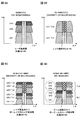
図9は、推定用参照信号の配置例の説明図である。例えば、図9では、無線基地局BS1-BS3(セル1-3)から送信される推定用参照信号は、それぞれ、衝突しないリソースエレメントにマッピングされる。また、各無線基地局BS(セル)内において、異なるビームで送信される推定用参照信号は、異なるリソースエレメントにマッピングされる。このように、図9では、各ビームの干渉推定情報の推定(チャネル推定)に用いられる推定用参照信号が、セル内で直交してセル間で衝突しないように、配置される。
また、図9では、自セルの推定用参照信号は、他セルのデータ信号と衝突するようにマッピングされる。自セルの推定用参照信号のマッピング位置において他セルのデータ信号を配置しない完全直交化を行う場合、オーバヘッドが大きいためである。なお、他セルのデータ信号は、自セルの推定用参照信号とは異なるビームフォーミングが施されているため、ユーザ端末UEは、自セルの推定用参照信号と他セルのデータ信号とを区別可能である。
また、図9において、k番目の無線基地局BSからのb’番目のビーム(k,b’)のi(i=1,…,L)番目のリソースエレメントにマッピングされる推定用参照信号をpk,b’,iとすると、当該推定用参照信号pk,b’,iの受信フィルタリング後の受信信号ベクトルyk,b’(長さL)は、下記式(3)で表わされる。
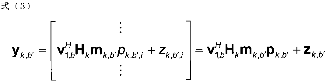
ここで、{pk,b’,i}は独立である。また、||pk,b’,i||2=Pk,b’である。また、pk,b’=[pk,b’,1,…,pk,b’,L]Tである。また、他セルのデータ信号による干渉のため、雑音電力N0の代わりに、zk,b’が考慮される。なお、zk,b’は、下記式(4)で表わされる。
また、k番目の無線基地局BSからのb’番目のビームによる干渉信号電力Rk,b’は、下記式(5)で表わされる。
しかしながら、図9に示すように、セル内で直交してセル間で衝突しないように推定用参照信号を配置する場合、以下の問題点がある。第1に、無線基地局BSは、周辺セルにおいて推定用参照信号が配置される無線リソース(リソースエレメント)と、当該推定用参照信号系列を把握している必要がある。第2に、距離の離れた周辺セルからの干渉信号電力Rk,b’の推定値には、大きな誤差が含まれる。第3に、周辺セルのデータ信号からの干渉が推定用参照信号に含まれるため、雑音電力N0の測定が困難となる。
そこで、第2態様に係る無線通信方法では、図10に示すように、全セルの全ビームの推定用参照信号を同一の無線リソースに配置することで、上記問題点を解決する。図10は、第2態様に係る無線通信方法における推定用参照信号の配置例の説明図である。
例えば、図10では、全無線基地局BS1-BS3(セル1-3)の全ビームの推定用参照信号が、同一のリソースエレメントにマッピングされる。図10において、全無線基地局BSの全ビームの推定用参照信号は、同一のリソースエレメントに符号分割多重される。かかる符号分割多重には、CAZAC(Constant Amplitude Zero Auto-Correlation)系列やWALSH符号などが用いられてもよい。なお、図10に示す配置は、全無線基地局BS1-BS3が同期すること(セル間同期)が前提となる。
図10において、k番目の無線基地局BSからのb’番目のビーム(k,b’)のi(i=1,…,F)番目のリソースエレメントにマッピングされる推定用参照信号をqk,b’,iとすると、当該推定用参照信号qk,b’,iの受信フィルタリング後の受信信号ベクトルyOL(長さF)は、下記式(6)で表わされる。

ここで、{qk,b’,i}は独立である。また、Ei[qk,b’,i]=0である。また、||qk,b’,i||2=Pk,b’である。また、qk,b’=[qk,b’,1,…,qk,b’,F]Tである。また、下記式(7)の関係が成り立つ。

図10において、qk,b’,iがi間で平均0かつ、k,b,i間で独立(略直交)となるように設計される場合、Fが十分大きければ、同一のリソースエレメントに多重された推定用参照信号の総受信電力と雑音電力N0との和が、下記式(8)で表わされる。
第2態様に係る無線通信方法において、タイミングT-Δより後のタイミングTにおけるビームフォーミング行列Mを用いてビームフォーミングされ、図10に示すように同一の無線リソースに多重される推定用参照信号が用いられる場合、ユーザ端末UEは、当該推定用参照信号に基づいて干渉推定情報を推定する(チャネル推定を行う)。かかる場合、ユーザ端末UEは、当該推定用参照信号と、既存参照信号に基づいて、干渉推定情報(例えば、SINR)を推定してもよい。
(1)既存参照信号を用いてSINRを推定する場合
かかる場合、ユーザ端末UEは、既存参照信号に基づいて希望信号電力を推定し、上述の推定用参照信号に基づいて干渉信号電力を推定してもよい。既存参照信号としては、例えば、CSI-RS(Channel State Information-Reference Signal)などが用いられてもよい。1番目の無線基地局BSからのb番目のビームのSINR1、bは、式(9)で表わされる。
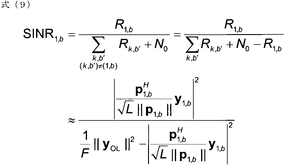
式(9)の分子では、既存参照信号(例えば、CSI-RS)の希望信号電力が表わされる。また、式(9)の分母では、式(8)で示される同一のリソースエレメントに多重された推定用参照信号の総受信電力と雑音電力N0との和から、既存参照信号の希望信号電力が減算される。これにより、図10に示すように同一リソースに多重される推定用参照信号と、既存参照信号とに基づいて、SINRを推定できる。
かかる場合、ユーザ端末UEは、既存参照信号に基づいて希望信号電力を推定し、上述の推定用参照信号に基づいて干渉信号電力を推定してもよい。既存参照信号としては、例えば、CSI-RS(Channel State Information-Reference Signal)などが用いられてもよい。1番目の無線基地局BSからのb番目のビームのSINR1、bは、式(9)で表わされる。
(2)既存参照信号を用いずにSINRを推定する場合
かかる場合、ユーザ端末UEは、上述の推定用参照信号に基づいて、希望信号電力と干渉信号電力との双方を推定してもよい。推定用参照信号に基づいて推定される希望信号電力は、式(10)で表わされる。
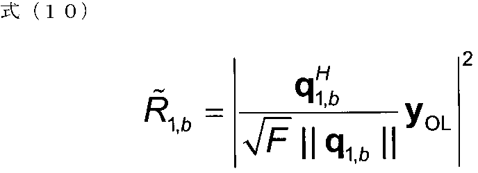
かかる場合、ユーザ端末UEは、上述の推定用参照信号に基づいて、希望信号電力と干渉信号電力との双方を推定してもよい。推定用参照信号に基づいて推定される希望信号電力は、式(10)で表わされる。
或いは、推定用参照信号に基づいて推定される希望信号電力は、式(11)で表わされてもよい。なお、式(11)は、ユーザ端末UEが、k番目の無線基地局BSからのb’番目のビームの推定用参照信号qk,b’の少なくとも一つを既知である場合を想定したものである。かかる場合、デコリレータも可能である。
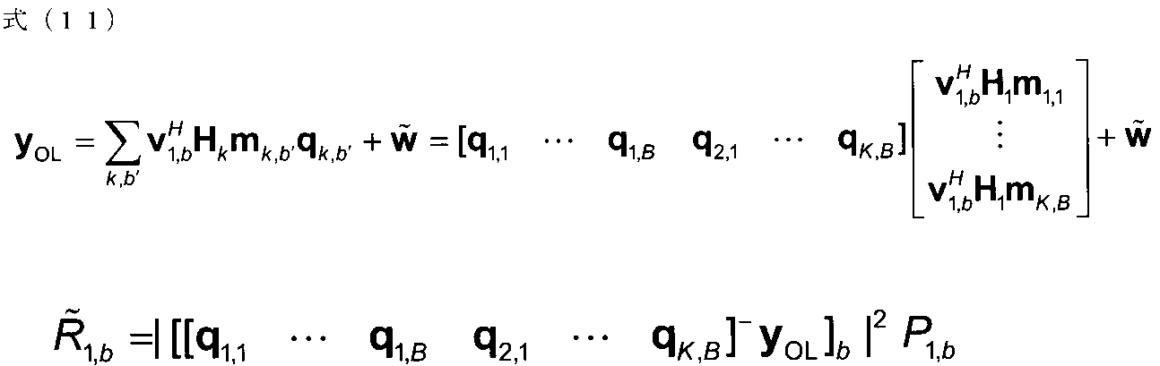
図11を参照し、第2態様に係る無線通信方法の動作を詳細に説明する。図11は、第2態様に係る無線通信方法を示すフローチャートである。以下では、無線基地局BS1と当該無線基地局BS1に接続するユーザ端末UEの動作を中心に説明する。なお、図11では、推定用参照信号が、OL型ビームフォーミングによりビームフォーミング(プリコーディング)されて送信される。
図11のステップS101において、無線基地局BS1は、タイミングT-Δ(第1タイミング)の次のタイミングT(第2タイミング)において下り信号(例えば、PDSCH)の伝送に用いられるビームフォーミング行列M1(T)(プリコーディング行列)を予め決定する。ここで、タイミングTにおけるビームフォーミング行列は、予め定められていてもよいし、ランダムであってもよい。
ステップS102において、無線基地局BS1は、タイミングT-Δにおいて、次のタイミングTにおけるビームフォーミング行列M1(T)を用いて、ビーム(ストリーム、レイヤ)数分の推定用参照信号をプリコーディングして送信する。同様に、周辺セルの各無線基地局BSも、次のタイミングTにおけるビームフォーミング行列M(T)を用いて、ビーム数分の推定用参照信号をプリコーディングして送信する。
また、ステップS102において、無線基地局BS1は、図10に示すように、自局からの全ビームの推定用参照信号を、周辺セルの全ビームの推定用参照信号と同一の無線リソースにマッピングする。これにより、図9に示すように、自局からの推定用参照信号をセル内で直交しセル間で重複しないようにマッピングする場合と比べて、干渉量の推定精度を向上させることができる。
ステップS103において、ユーザ端末UEは、無線基地局BS1からの各ビームについて干渉推定(チャネル推定)を行い、各ビーム(ストリーム、レイヤ)の干渉推定情報(例えば、SINR)を無線基地局BS1にフィードバックする。ここで、ユーザ端末UEは、式(9)に示されるように、既存参照信号(例えば、CSI-RS)と上述の推定用参照信号とに基づいてSINRを推定してもよい。或いは、ユーザ端末UEは、式(11)に示されるように、既存参照信号を用いずに、上述の推定用参照信号に基づいてSINRを推定してもよい。
ステップS104において、無線基地局BS1は、ユーザ端末UEからフィードバックされた各ビームの干渉推定情報に基づいて、各ビーム(ストリーム、レイヤ)に適切なユーザ端末UEをスケジューリングする。例えば、無線基地局BS1は、各ビームのSINRが最も高いユーザ端末UEを選択して、各ビームに割り当てる。
ステップS105において、無線基地局BS1は、ステップS104によるスケジューリング結果に基づいて、今回のタイミングTにおける下り信号(例えば、PDSCH)をプリコーディングして送信する。
なお、ステップS105において、下り信号は、第1態様に係る無線通信方法において、ユーザ端末UEに設定される送信モードに基づいて、送信されてもよい。また、かかる送信モードは、ステップS103でフィードバックされる干渉推定情報に基づいて準静的に変更されてもよい。また、送信モードでサポートされる複数の送信法も、ステップS103でフィードバックされる干渉推定情報に基づいて動的に変更されてもよい。
以上の第2態様に係る無線通信方法によれば、推定用参照信号による干渉推定情報に基づいて下り信号が送信されるタイミングTのビームフォーミング行列M1(T)及びM2(T)を用いてビームフォーミングされるとともに、周辺セルの全ビームの推定用参照信号と同一の無線リソースに多重されて、推定用参照信号が送信されるため、干渉推定情報の精度を向上できる。
以上の第2態様に係る無線通信方法は、無線基地局BSがユーザ端末UEに対する下り信号を送信する無線通信システムにおける無線通信方法であって、無線基地局BSにおいて、ユーザ端末UEにおける干渉推定情報の推定に用いられる推定用参照信号を、周辺の無線基地局BSと同一の無線リソースにマッピングする工程と、当該推定用参照信が送信される第1タイミングのビームフォーミング行列の代わりに、当該推定用参照信号による干渉推定情報に基づいて下り信号が送信される第2タイミングのビームフォーミング行列を用いて、当該推定用参照信号を送信する工程と、を有する。
(無線通信システムの構成)
以下、本実施の形態に係る無線通信システムの構成について説明する。この無線通信システムでは、上述の無線通信方法(第1態様、第2態様を含む)が適用される。図12-図15を参照し、本実施の形態に係る無線通信システムの概略構成を説明する。
以下、本実施の形態に係る無線通信システムの構成について説明する。この無線通信システムでは、上述の無線通信方法(第1態様、第2態様を含む)が適用される。図12-図15を参照し、本実施の形態に係る無線通信システムの概略構成を説明する。
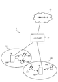
図12に示すように、無線通信システム1は、無線基地局10(10A,10B)、及び複数のユーザ端末20(20A,20B)を含んでいる。無線基地局10は、上位局装置30と接続され、この上位局装置30は、コアネットワーク40と接続される。各ユーザ端末20は、セルC1,C2において無線基地局10と通信を行うことができる。この無線通信システム1において、ユーザ端末20は、移動端末でも良いし固定端末でもよい。なお、上位局装置30には、例えば、アクセスゲートウェイ装置、無線ネットワークコントローラ(RNC)、モビリティマネジメントエンティティ(MME)等が含まれるが、これらに限定されない。
無線通信システム1においては、無線アクセス方式として、下りリンクにOFDMA(Orthogonal Frequency Division Multiple Access)が適用され、上りリンクにSC-FDMA(Single Carrier Frequency Division Multiple Access)が適用される。OFDMAは、周波数帯域を複数の狭い周波数帯域(サブキャリア)に分割し、各サブキャリアにデータをマッピングして通信を行うマルチキャリア伝送方式である。SC-FDMAは、システム帯域を端末毎に1つ又は連続したリソースブロックからなる帯域に分割し、複数の端末が互いに異なる帯域を用いることで、端末間の干渉を低減するシングルキャリア伝送方式である。この無線通信システム1の下りリンクには、必要に応じてNOMAが適用される。
ここで、図12に示す無線通信システム1で用いられる通信チャネルについて説明する。下りリンクの通信チャネルは、各ユーザ端末20で共有される下り共有チャネルとしてのPDSCH(Physical Downlink Shared CHannel)と、下りL1/L2制御チャネル(PDCCH、PCFICH、PHICH、EPDCCH)とを有する。PDSCHにより、ユーザデータ及び上位制御情報が伝送される。PDCCH(Physical Downlink Control CHannel)により、PDSCH及びPUSCHのスケジューリング情報などが伝送される。PCFICH(Physical Control Format Indicator CHannel)により、PDCCHに用いるOFDMシンボル数が伝送される。PHICH(Physical Hybrid-ARQ Indicator CHannel)により、PUSCHに対するHARQのACK/NACKが伝送される。
上りリンクの通信チャネルは、各ユーザ端末20で共有される上り共有チャネルとしてのPUSCH(Physical Uplink Shared CHannel)と、上りリンクの制御チャネルであるPUCCH(Physical Uplink Control CHannel)とを有する。このPUSCHにより、ユーザデータや上位制御情報が伝送される。また、PUCCH又はPUSCHにより、下りリンクの干渉推定情報(CQI、SINRなど)、送達確認情報(ACK/NACK/DTX)などが伝送される。
図13は、本実施の形態に係る無線基地局の概略構成図である。無線基地局10は、ビームフォーミングのための複数の送受信アンテナ101と、アンプ部102と、送受信部103と、ベースバンド信号処理部104と、呼処理部105と、伝送路インターフェース106とを備えている。
下りリンクにおいて無線基地局10からユーザ端末20に送信されるユーザデータは、上位局装置30から伝送路インターフェース106を介してベースバンド信号処理部104に入力される。
ベースバンド信号処理部104は、入力されたユーザデータに対して、PDCPレイヤの処理、ユーザデータの分割・結合、RLC(Radio Link Control)再送制御の送信処理などのRLCレイヤの送信処理、MAC(Medium Access Control)再送制御、例えば、HARQの送信処理、スケジューリング、伝送フォーマット選択、チャネル符号化、逆高速フーリエ変換(IFFT:Inverse Fast Fourier Transform)処理、プリコーディング処理などを行い、各送受信部103に転送する。また、下りリンクの制御情報に対してチャネル符号化やIFFT処理などの送信処理を行い、各送受信部103に転送する。
また、ベースバンド信号処理部104は、報知チャネルにより、ユーザ端末20に対して、在圏セルにおける通信のための制御情報を通知する。在圏セルにおける通信のための情報には、例えば、上りリンク又は下りリンクにおけるシステム帯域幅などが含まれる。
各送受信部103は、ベースバンド信号処理部104からアンテナ毎にプリコーディングして出力されたベースバンド信号を無線周波数帯に変換する。アンプ部102は、周波数変換された無線周波数信号を増幅して送受信アンテナ101より送信する。
一方、上りリンクによりユーザ端末20から無線基地局10に送信されるデータは、各送受信アンテナ101で受信されてアンプ部102に入力される。アンプ部102は、各送受信アンテナ101から入力される無線周波数信号を増幅して各送受信部103に送る。増幅された無線周波数信号は、各送受信部103でベースバンド信号に変換され、ベースバンド信号処理部104に入力される。
ベースバンド信号処理部104は、入力されたベースバンド信号に含まれるユーザデータに対して、高速フーリエ変換(FFT: Fast Fourier Transform)処理、逆離散フーリエ変換(IDFT:Inverse Discrete Fourier Transform)処理、誤り訂正復号、MAC再送制御の受信処理、RLCレイヤ、PDCPレイヤの受信処理などを行い、伝送路インターフェース106を介して上位局装置30に転送する。呼処理部105は、通信チャネルの設定や解放などの呼処理、無線基地局10の状態管理、無線リソースの管理などを行う。
図14は、本実施の形態に係るユーザ端末の概略構成図である。ユーザ端末20は、複数の送受信アンテナ201と、アンプ部202と、送受信部203と、ベースバンド信号処理部204と、アプリケーション部205とを備えている。
下りリンクのデータは、複数の送受信アンテナ201で受信されてアンプ部202に入力される。アンプ部202は、各送受信アンテナ201から入力される無線周波数信号を増幅して各送受信部203に送る。増幅された無線周波数信号は、各送受信部203でベースバンド信号に変換され、ベースバンド信号処理部204に入力される。ベースバンド信号処理部204では、入力されたベースバンド信号に対してFFT処理、誤り訂正復号、再送制御の受信処理などが行われる。下りリンクのデータに含まれるユーザデータは、アプリケーション部205に転送される。アプリケーション部205は、物理レイヤやMACレイヤより上位のレイヤに関する処理などを行う。また、下りリンクのデータに含まれる報知情報もアプリケーション部205に転送される。
一方、上りリンクのユーザデータは、アプリケーション部205からベースバンド信号処理部204に入力される。ベースバンド信号処理部204は、入力されたユーザデータに対して、再送制御の送信処理、チャネル符号化、プリコーディング、離散フーリエ変換(DFT:Discrete Fourier Transform)処理、IFFT処理などを行い、各送受信部203に転送する。各送受信部203は、ベースバンド信号処理部204から出力されたベースバンド信号を無線周波数帯に変換する。その後、アンプ部202は、周波数変換された無線周波数信号を増幅して送受信アンテナ201より送信する。
次に、図15を参照し、無線基地局10及びユーザ端末20の機能構成について詳述する。図15は、本実施の形態に係る無線基地局及びユーザ端末の機能構成図である。なお、図15に示す機能構成は、ベースバンド信号処理部104、204などにより構成される。また、図15では、構成の一部のみを示しているが、無線基地局10及びユーザ端末20は、必要な構成を不足なく備えているものとする。
図15に示すように、無線基地局10は、スケジューリング部111、送信モード設定部112、下り制御情報(DCI)生成部113、下りデータ生成部114、参照信号生成部115、プリコーディング部116を具備する。
スケジューリング部111は、ユーザ端末20からの干渉推定情報に基づいて、スケジューリングを行う。上述のように、干渉推定情報は、受信SINR、パスロス、CQI、SNR、CSIなど、ユーザ端末UEにおける干渉量やチャネル品質を示すどのような情報であってもよい。具体的には、スケジューリング部111は、干渉推定情報に基づいて、空間多重又は及び非直交多重されるユーザ端末20を決定して無線リソースを割り当てる。また、スケジューリング部111は、非直交多重されるユーザ端末20の送信電力を決定してもよい。
送信モード設定部112(設定部)は、複数の送信法がグループ化される第1送信モードと、複数の送信法がグループ化される第2送信モードと、を含む複数の送信モードの一つを、ユーザ端末20に対して設定(configure)する。また、送信モード設定部112は、上位レイヤシグナリング(例えば、RRCシグナリング)を用いて、前記ユーザ端末に対して設定された送信モードを切り替える。また、送信モード設定部112は、上位レイヤシグナリングよりも下位レイヤのシグナリング(例えば、MACシグナリング)又はDCIを用いて、送信モードでグループ化される複数の送信法のうち下り信号に適用される送信法を切り替える。
なお、上述の通り、第1送信モード及び第2送信モードにおける送信法のグループ化は、ユーザ端末UEからのフィードバック情報を要する送信法であるか否か(閉ループか、開ループか)によって行われてもよいし、MIMOであるか送信ダイバーシチであるかによって行われてもよい。また、第1送信モード及び第2送信モードの双方に重複する送信法が含まれてもよい。
DCI生成部113は、PDCCH又はEPDCCHで伝送される下り制御情報(DCI)を生成して送信処理(例えば、符号化、変調、無線リソースへのマッピングなど)を行う。DCIには、PDSCH/PUSCHの割り当て情報などが含まれる。また、DCIには、非直交で多重された信号の受信処理に必要な各種の情報が含まれる。また、DCIには、ユーザ端末20に設定(configure)される送信モード内での送信法の切り替え情報が含まれてもよい。
下りデータ生成部114は、PDSCHで伝送される下りユーザデータ及び上位レイヤ制御情報を生成し、送信モード設定部112によって設定される送信モードに基づいて送信処理(例えば、符号化、変調、無線リソースへのマッピングなど)を行う。上位レイヤ制御情報には、上位レイヤシグナリング(例えば、RRCシグナリング)や、上位レイヤシグナリングよりも下位レイヤのシグナリング(例えば、MACシグナリング)で伝送される制御情報が含まれる。また、上位レイヤ制御情報には、ユーザ端末UEに対する送信モードの設定情報や切り替え情報が含まれてもよい。また、MACシグナリングによる制御情報には、上述の送信法の切り替え情報が含まれても良い。
参照信号生成部115は、CRS(Cell-specific Reference Signal)、CSI-RS、DM-RS(図6)、推定用参照信号(図10)などの参照信号を生成して送信処理(例えば、符号化、変調、無線リソースへのマッピングなど)を行う。図6で説明したように、復調用参照信号として用いられるDM-RSは、ユーザ端末20間で共通であってもよい。また、図10で説明したように、推定用参照信号は、ユーザ端末20における干渉推定情報の推定に用いられる参照信号であり、周辺の無線基地局10及び全ビーム(ストリーム、レイヤ)間で同一の無線リソース(リソースエレメント)にマッピングされてもよい。
プリコーディング部116は、下りデータ生成部114から出力される下り信号と参照信号生成部115から出力される参照信号をプリコーディング(ビームフォーミング)して送信する。具体的には、プリコーディング部116は、下り信号に対応したビームフォーミング行列を用いてDM-RSをプリコーディングして送信する。
また、プリコーディング部116は、推定用参照信号が送信されるタイミングT-Δ(第1タイミング)におけるビームフォーミング行列M(T-Δ)の代わりに、該参照信号による干渉推定情報に基づいて下り信号が送信されるタイミング(第2タイミング)におけるビームフォーミング行列M(T)を用いて、推定用参照信号を送信する。
図15に示すように、ユーザ端末20は、干渉推定部211、DCI受信処理部212、下りデータ受信処理部213、送信モード設定部214を備えている。
干渉推定部211は、無線基地局10からの推定用参照信号に基づいて、干渉推定情報を推定する(チャネル推定を行う)。干渉推定部211は、式(9)に示されるように、当該推定用参照信号と、既存参照信号(例えば、CSI-RS)に基づいて、干渉推定情報(例えば、SINR)を推定してもよい。或いは、干渉推定部211は、式(10)に示されるように、既存参照信号(例えば、CSI-RS)を用いずに、推定用参照信号を用いて、干渉推定情報を推定してもよい。
DCI受信処理部212は、無線基地局10からのDCIをブラインド復号して、受信処理(例えば、デマッピング、復調、復号など)を行う。上述のように、DCIには、ユーザ端末20に設定される送信モード内での送信法の切り替え情報が含まれてもよい。
下りデータ受信処理部213は、無線基地局10からの下りデータ(上位レイヤ制御情報を含む)の受信処理(例えば、IRC、SIC、デマッピング、復調、復号など)を行う。IRCなどの線形フィルタリングにより、干渉ビームが除去されて、自端末に対するビームが抽出される。また、SICにより、同一ビームに多重された他のユーザ端末20に対する下り信号(干渉信号)が除去されて、自端末に対する下り信号が抽出される。
また、下りデータ受信処理部213は、ユーザ端末20間で共通のDM-RSとユーザ端末20間の送信電力比に基づいて、下りデータを復調してもよい。また、上述のように、上位レイヤ制御情報には、ユーザ端末20に設定される送信モードの設定情報又は切り替え情報が含まれてもよい。
送信モード設定部214は、上述の送信モードの設定情報又は切り替え情報に基づいて、ユーザ端末UEの送信モードを設定し、当該送信モードに基づいて下りデータの受信処理を行うよう、下りデータ受信処理部213を制御する。また、送信モード設定部214は、ユーザ端末20に設定される送信モード内での送信法の切り替え情報に基づいて、送信法に応じた下りデータの受信処理を行うよう、下りデータ受信処理部213を制御してもよい。
以上のように、本実施の形態に係る無線通信システム1によれば、非直交多重アクセス(NOMA)を利用可能な無線通信システムにおいて、NOMA/MU-MIMOに対応した送信モードが規定されるので、周波数利用効率を向上させることができる。NOMA/MU-MIMOを含む複数の送信法をグループ化した第1送信モードと、NOMA/開ループ送信ダイバーシチを含む複数の送信方法をグループ化した第2送信モードとが規定されるので、制御負荷を増大せずに、多様な送信法をサポートできる(第1態様)。
また、本実施の形態に係る無線通信システム1によれば、推定用参照信号による干渉推定情報に基づいて下り信号が送信されるタイミングTのビームフォーミング行列M1(T)及びM2(T)を用いてビームフォーミングされるとともに、周辺セルの全ビームの推定用参照信号と同一の無線リソースに多重されて、推定用参照信号が送信されるため、干渉推定情報の精度を向上できる(第2態様)。
本発明は、その趣旨及び範囲を逸脱することなく修正及び変更態様として実施できる。つまり、本明細書の記載は、例示を目的とするものに過ぎず、本発明に対して制限を加えるものではない。
本出願は、2013年2月6日出願の特願2013-021269に基づく。この内容は、全てここに含めておく。
Claims (10)
- ユーザ端末に対する下り信号を送信する無線基地局であって、
非直交多重アクセス(NOMA)とマルチユーザ多入力多出力(MU-MIMO)とを用いた送信法を含む複数の送信法がグループ化される第1送信モードと、前記NOMAと開ループ送信ダイバーシチとを用いた送信法を含む複数の送信法がグループ化される第2送信モードと、を含む複数の送信モードの一つを、前記ユーザ端末に対して設定する設定部と、
前記設定部によって設定される送信モードに基づいて、前記下り信号を送信する送信部と、を具備することを特徴とする無線基地局。 - 前記設定部は、上位レイヤシグナリングを用いて、前記ユーザ端末に対して設定された送信モードを切り替えることを特徴とする請求項1に記載の無線基地局。
- 前記設定部は、前記上位レイヤシグナリングよりも下位レイヤのシグナリング又は下り制御チャネルを用いて、前記送信モードでグループ化される複数の送信法のうち前記下り信号に適用される送信法を切り替えることを特徴とする請求項2に記載の無線基地局。
- 前記第1送信モードでは、前記NOMAと前記MU-MIMOを用いた送信法に加えて、前記NOMAと閉ループ送信ダイバーシチとを用いた送信法、前記NOMAとシングルユーザ多入力多出力(SU-MIMO)とを用いた送信法、前記NOMAを用いずに前記閉ループ送信ダイバーシチを用いた送信法、前記NOMAを用いずに前記SU-MIMOを用いた送信法、の少なくとも一つがグループ化されることを特徴とする請求項1から請求項3のいずれかに記載の無線基地局。
- 前記第2送信モードでは、前記NOMAと前記開ループ送信ダイバーシチとを用いた送信法に加えて、前記NOMAとシングルユーザ多入力多出力(SU-MIMO)とを用いた送信法、前記NOMAを用いずに前記開ループ送信ダイバーシチを用いた送信法、前記NOMAを用いずに前記SU-MIMOを用いた送信法、の少なくとも一つがグループ化されることを特徴とする請求項1から請求項3のいずれかに記載の無線基地局。
- 前記設定部は、前記ユーザ端末からの干渉推定情報に基づいて、前記複数の送信モードの一つを前記ユーザ端末に対して設定又は切り替え、
前記送信部は、前記ユーザ端末における前記干渉推定情報の推定に用いられる参照信号をビームフォーミングして送信することを特徴とする請求項1から請求項3のいずれかに記載の無線基地局。 - 前記送信部は、前記参照信号が送信される第1タイミングにおけるビームフォーミング行列の代わりに、該参照信号による干渉推定情報に基づいて前記下り信号が送信される第2タイミングにおけるビームフォーミング行列を用いて、前記参照信号を送信することを特徴とする請求項6に記載の無線基地局。
- 前記送信部は、他の無線基地局から送信される参照信号と同一の無線リソースにマッピングして、前記参照信号を送信することを特徴とする請求項7に記載の無線基地局。
- 無線基地局から下り信号を受信するユーザ端末であって、
非直交多重アクセス(NOMA)とマルチユーザ多入力多出力(MU-MIMO)とを用いた送信法を含む複数の送信法がグループ化される第1送信モードと、前記NOMAと開ループ送信ダイバーシチとを用いた送信法を含む複数の送信法がグループ化される第2送信モードと、を含む複数の送信モードの一つを示す送信モード情報を、前記無線基地局から受信する受信部と、
前記送信モード情報が示す送信モードに基づいて、前記下り信号の受信処理を行う受信処理部と、を具備することを特徴とするユーザ端末。 - 無線基地局がユーザ端末に対する下り信号を送信する無線通信システムにおける無線通信方法であって、
前記無線基地局が、非直交多重アクセス(NOMA)とマルチユーザ多入力多出力(MU-MIMO)とを用いた送信法を含む複数の送信法がグループ化される第1送信モードと、前記NOMAと開ループ送信ダイバーシチとを用いた送信法を含む複数の送信法がグループ化される第2送信モードと、を含む複数の送信モードの一つを、前記ユーザ端末に対して設定する工程と、
前記無線基地局が、設定された送信モードに基づいて、前記下り信号を送信する工程と、を有することを特徴とする無線通信方法。
Priority Applications (2)
| Application Number | Priority Date | Filing Date | Title |
|---|---|---|---|
| EP14749132.8A EP2955952A4 (en) | 2013-02-06 | 2014-01-22 | RADIO BASE STATION, USER TERMINAL AND RADIO COMMUNICATION METHOD |
| US14/765,965 US10251166B2 (en) | 2013-02-06 | 2014-01-22 | Radio base station, user terminal and radio communication method |
Applications Claiming Priority (2)
| Application Number | Priority Date | Filing Date | Title |
|---|---|---|---|
| JP2013021269A JP5830478B2 (ja) | 2013-02-06 | 2013-02-06 | 無線基地局、ユーザ端末及び無線通信方法 |
| JP2013-021269 | 2013-02-06 |
Publications (1)
| Publication Number | Publication Date |
|---|---|
| WO2014122994A1 true WO2014122994A1 (ja) | 2014-08-14 |
Family
ID=51299591
Family Applications (1)
| Application Number | Title | Priority Date | Filing Date |
|---|---|---|---|
| PCT/JP2014/051252 WO2014122994A1 (ja) | 2013-02-06 | 2014-01-22 | 無線基地局、ユーザ端末及び無線通信方法 |
Country Status (4)
| Country | Link |
|---|---|
| US (1) | US10251166B2 (ja) |
| EP (1) | EP2955952A4 (ja) |
| JP (1) | JP5830478B2 (ja) |
| WO (1) | WO2014122994A1 (ja) |
Cited By (22)
| Publication number | Priority date | Publication date | Assignee | Title |
|---|---|---|---|---|
| CN104158631A (zh) * | 2014-08-27 | 2014-11-19 | 北京邮电大学 | 一种数据流的发射方法及装置 |
| CN104836602A (zh) * | 2015-03-31 | 2015-08-12 | 重庆大学 | 一种分布式大规模mimo-noma高铁移动通信系统 |
| WO2016027646A1 (ja) * | 2014-08-20 | 2016-02-25 | シャープ株式会社 | 端末装置、基地局装置および通信方法 |
| WO2016070657A1 (zh) * | 2014-11-07 | 2016-05-12 | 中兴通讯股份有限公司 | 一种下行非正交多址接入时的解码方法及装置 |
| WO2016159736A1 (ko) * | 2015-04-02 | 2016-10-06 | 삼성전자 주식회사 | 무선 통신 시스템에서 다운링크 정보를 송신하는 방법 및 장치 |
| WO2016165095A1 (zh) * | 2015-04-16 | 2016-10-20 | 富士通株式会社 | 信息传输方法、装置以及通信系统 |
| WO2016171494A1 (ko) * | 2015-04-22 | 2016-10-27 | 엘지전자 주식회사 | 무선 통신 시스템에서 신호를 송수신하는 방법 및 이를 수행하는 장치 |
| CN106160960A (zh) * | 2015-04-15 | 2016-11-23 | 上海朗帛通信技术有限公司 | 一种功分复用的通信方法和装置 |
| WO2016200066A1 (ko) * | 2015-06-11 | 2016-12-15 | 엘지전자 주식회사 | 무선 통신 시스템에서 비직교다중접속을 위한 다중 사용자 선택 및 자원 할당 방법 및 장치 |
| CN106304349A (zh) * | 2015-05-22 | 2017-01-04 | 中兴通讯股份有限公司 | 数据传输方法及装置 |
| WO2017011107A1 (en) * | 2015-07-10 | 2017-01-19 | Qualcomm Incorporated | Reference signal and signalling design for non-orthogonal multiple access with legacy user equipment as a base layer |
| WO2017074014A1 (ko) * | 2015-11-01 | 2017-05-04 | 엘지전자 주식회사 | 무선 통신 시스템에서 must 전송을 위한 제어 정보 전송 방법 및 이를 위한 장치 |
| JPWO2016027556A1 (ja) * | 2014-08-21 | 2017-06-29 | 株式会社Nttドコモ | 基地局、ユーザ装置および無線通信システム |
| WO2017121269A1 (zh) * | 2016-01-13 | 2017-07-20 | 索尼公司 | 无线通信系统中的电子设备、用户设备和无线通信方法 |
| JPWO2016038960A1 (ja) * | 2014-09-11 | 2017-07-20 | 株式会社Nttドコモ | 基地局、ユーザ装置および無線通信システム |
| JPWO2016103831A1 (ja) * | 2014-12-25 | 2017-10-05 | ソニー株式会社 | 装置及び方法 |
| EP3245832A4 (en) * | 2015-08-14 | 2018-01-17 | JRD Communication Inc. | Systems and methods for multi-user communication |
| CN107615856A (zh) * | 2015-05-28 | 2018-01-19 | 华为技术有限公司 | 用于多级波束成形的非正交多址通信的系统和方法 |
| WO2018033090A1 (zh) * | 2016-08-19 | 2018-02-22 | 株式会社Ntt都科摩 | 用于控制发射功率的方法、移动台和基站 |
| JP2019503608A (ja) * | 2015-12-02 | 2019-02-07 | クアルコム,インコーポレイテッド | 混合干渉管理のためのシステムおよび方法 |
| US10651988B2 (en) | 2015-06-11 | 2020-05-12 | Lg Electronics Inc. | Method and device for selecting multiple users and allocating resources for non-orthogonal multiple access in wireless communication system |
| CN112566159A (zh) * | 2020-11-27 | 2021-03-26 | 暨南大学 | 一种基于mimo-noma的增强型小蜂窝下行通信方法 |
Families Citing this family (42)
| Publication number | Priority date | Publication date | Assignee | Title |
|---|---|---|---|---|
| US10003486B2 (en) * | 2014-04-28 | 2018-06-19 | Intel IP Corporation | Non-orthogonal multiple access (NOMA) wireless systems and methods |
| CN105227273B (zh) * | 2014-07-02 | 2019-09-17 | 电信科学技术研究院 | 一种数据传输的方法、系统和设备 |
| US10149318B2 (en) * | 2014-09-02 | 2018-12-04 | Qualcomm Incorporated | Techniques for transmitting and receiving downlink control information for a set of NOMA downlink transmissions |
| US10063672B2 (en) * | 2014-10-02 | 2018-08-28 | Acer Incorporated | Device and method of handling parameter configurations |
| JP2017208586A (ja) * | 2014-10-03 | 2017-11-24 | シャープ株式会社 | 基地局装置、端末装置 |
| US10117120B2 (en) * | 2014-10-28 | 2018-10-30 | Qualcomm Incorporated | Channel feedback for non-orthogonal multiple access systems |
| US10326560B2 (en) | 2014-11-03 | 2019-06-18 | Lg Electronics Inc. | Data buffering method and apparatus for hybrid automatic repeat request in wireless access system supporting non-orthogonal multiple access scheme |
| US10396930B2 (en) | 2014-11-04 | 2019-08-27 | Lg Electronics Inc. | NOMA scheme data receiving method and user equipment |
| WO2016084460A1 (ja) * | 2014-11-28 | 2016-06-02 | ソニー株式会社 | 装置及び方法 |
| US9780847B2 (en) * | 2015-03-27 | 2017-10-03 | Qualcomm Incorporated | Channel feedback design for frequency selective channels |
| WO2016163499A1 (ja) * | 2015-04-09 | 2016-10-13 | 株式会社Nttドコモ | 無線基地局、ユーザ端末、無線通信システム及び無線通信方法 |
| US10554280B2 (en) * | 2015-05-01 | 2020-02-04 | Futurewei Technologies, Inc. | Device, network, and method for CSI feedback of hybrid beamforming |
| JP2018107483A (ja) * | 2015-05-08 | 2018-07-05 | シャープ株式会社 | 端末装置および基地局装置 |
| US9590711B2 (en) * | 2015-05-11 | 2017-03-07 | International Business Machines Corporation | Managing beamformed signals to optimize transmission rates of sensor arrays |
| WO2016179779A1 (zh) * | 2015-05-11 | 2016-11-17 | 华为技术有限公司 | 基于半正交传输的通信方法和设备 |
| CN106454922B (zh) * | 2015-08-10 | 2018-11-02 | 电信科学技术研究院 | 一种非正交多址接入系统中的上行检测方法及装置 |
| WO2017037861A1 (ja) * | 2015-08-31 | 2017-03-09 | 富士通株式会社 | 基地局、端末、無線通信システムおよび無線通信方法 |
| KR102201778B1 (ko) * | 2015-09-02 | 2021-01-12 | 에스케이텔레콤 주식회사 | 통신모드제어장치 및 통신모드 제어 방법 |
| CN106685863B (zh) | 2015-11-05 | 2021-02-26 | 索尼公司 | 无线通信系统中的装置和方法 |
| KR102391724B1 (ko) * | 2015-12-18 | 2022-04-28 | 삼성전자주식회사 | 무선 통신 시스템에서 비직교 다중 접속을 위한 장치 및 방법 |
| CN106911372A (zh) * | 2015-12-22 | 2017-06-30 | 电信科学技术研究院 | 一种确定多用户传输方式的方法及装置 |
| CN106961404A (zh) * | 2016-01-11 | 2017-07-18 | 中兴通讯股份有限公司 | 一种发射信号处理方法及装置 |
| US10524150B2 (en) | 2016-01-14 | 2019-12-31 | Samsung Electronics Co., Ltd. | Method and apparatus for generating cell measurement information in a wireless communication system |
| JP6532832B2 (ja) * | 2016-02-15 | 2019-06-19 | 日本電信電話株式会社 | 通信システム、通信方法および通信装置 |
| WO2017152962A1 (en) * | 2016-03-08 | 2017-09-14 | Huawei Technologies Co., Ltd. | Client and access point communication devices allocating indicated portion of uplink frame for multiple types of control data |
| JP2019091964A (ja) * | 2016-03-31 | 2019-06-13 | シャープ株式会社 | 基地局装置、端末装置及びその通信方法 |
| CN107302414B (zh) * | 2016-04-14 | 2020-06-19 | 中国移动通信有限公司研究院 | 一种传输模式自适应切换方法及装置 |
| CN107302415B (zh) * | 2016-04-14 | 2019-11-19 | 中国移动通信有限公司研究院 | 一种非正交数据重传模式的选择方法及装置 |
| CN109417784B (zh) * | 2016-05-02 | 2023-10-03 | 瑞典爱立信有限公司 | 用于处理无线电资源的网络节点、无线装置和方法 |
| US10181891B2 (en) | 2016-05-26 | 2019-01-15 | Qualcomm Incorporated | System and method for beam switching and reporting |
| CN107453794B (zh) * | 2016-05-31 | 2020-12-08 | 中兴通讯股份有限公司 | 信息反馈方法、装置及系统 |
| CN109302856B (zh) * | 2016-06-20 | 2021-06-01 | 三菱电机株式会社 | 发送装置、通信系统和预编码运算方法 |
| KR102594859B1 (ko) * | 2016-07-13 | 2023-10-31 | 삼성전자주식회사 | 무선 통신 시스템에서 신호를 송/수신하는 장치 및 방법 |
| BR112019006514A2 (pt) | 2016-09-30 | 2019-10-01 | Huawei Tech Co Ltd | método de processamento de mensagem, aparelho e meio legível por computador |
| CN106788651B (zh) * | 2017-01-22 | 2020-05-22 | 西安交通大学 | 基于非正交多址接入的多地理区域广播系统的信息传输方法 |
| CN108418619B (zh) * | 2017-02-09 | 2020-08-28 | 电信科学技术研究院 | 一种信号检测方法及装置 |
| US10666374B2 (en) | 2018-05-11 | 2020-05-26 | At&T Intellectual Property I, L.P. | Non-orthogonal multiple access for uplink data transmission for 5G or other next generation network |
| CN110661557B (zh) * | 2018-06-29 | 2021-08-24 | 中兴通讯股份有限公司 | 基于mumimo进行模式切换的方法、设备和存储介质 |
| JP7140907B2 (ja) * | 2019-03-25 | 2022-09-21 | 株式会社日立国際電気 | 無線通信装置 |
| CN111313988B (zh) * | 2020-02-22 | 2021-06-08 | 吉林大学 | 基于鞅变换模型实现urllc的免授权noma方法 |
| CN114285446A (zh) * | 2020-09-27 | 2022-04-05 | 北京三星通信技术研究有限公司 | 大规模多输入多输出系统中的传输方式切换方法及装置 |
| CN115037394B (zh) * | 2022-05-11 | 2023-07-28 | 南京邮电大学 | 基于GSIC的多RISs辅助的NOMA系统设计方法 |
Citations (1)
| Publication number | Priority date | Publication date | Assignee | Title |
|---|---|---|---|---|
| JP2013247513A (ja) * | 2012-05-25 | 2013-12-09 | Sharp Corp | 受信局装置、送信局装置、通信システム、受信方法、送信方法及びプログラム |
Family Cites Families (22)
| Publication number | Priority date | Publication date | Assignee | Title |
|---|---|---|---|---|
| CN103297204B (zh) * | 2004-04-02 | 2017-03-01 | 苹果公司 | 用于正交频分复用应用的空间时间发射分集系统及方法 |
| US20090316807A1 (en) * | 2006-01-13 | 2009-12-24 | Sang Gook Kim | Method and apparatus for achieving transmit diversity and spatial multiplexing using antenna selection based on feedback information |
| DK3145096T3 (en) | 2007-10-31 | 2018-09-17 | Ericsson Telefon Ab L M | SELECTION OF SENDING MODE IN A RANDOM ACCESS PROCEDURE |
| WO2009081514A1 (ja) | 2007-12-25 | 2009-07-02 | Panasonic Corporation | 無線通信装置、無線通信システム及び無線通信方法 |
| US8233559B2 (en) * | 2008-03-12 | 2012-07-31 | Lg Electronics Inc. | Method and apparatus for transmitting a pilot in multi-antenna system |
| WO2011008013A2 (ko) * | 2009-07-13 | 2011-01-20 | 엘지전자 주식회사 | 백홀 링크 전송을 위한 전송 모드 구성 방법 및 장치 |
| US20110019776A1 (en) * | 2009-07-24 | 2011-01-27 | Interdigital Patent Holdings, Inc. | Method and apparatus for obtaining port index information |
| US8768397B2 (en) * | 2009-10-02 | 2014-07-01 | Sharp Kabushiki Kaisha | Transmission power control on a wireless communication device for a plurality of regulated bands or component carriers |
| WO2011096646A2 (en) * | 2010-02-07 | 2011-08-11 | Lg Electronics Inc. | Method and apparatus for transmitting downlink reference signal in wireless communication system supporting multiple antennas |
| KR101492924B1 (ko) * | 2010-11-08 | 2015-02-12 | 블랙베리 리미티드 | 무선 자원들 |
| EP2706788A4 (en) | 2011-05-06 | 2015-04-22 | Fujitsu Ltd | TRANSMIT MODE CONFIGURATION METHOD, USER EQUIPMENT AND BASE STATION THEREOF |
| JP5785845B2 (ja) | 2011-05-20 | 2015-09-30 | 株式会社Nttドコモ | 受信装置、送信装置及び無線通信方法 |
| CN102868480B (zh) * | 2011-07-07 | 2016-06-08 | 华为技术有限公司 | 控制信令的检测、发送方法及用户设备、基站 |
| EP2774310B1 (en) * | 2011-11-04 | 2020-01-01 | Telefonaktiebolaget LM Ericsson (publ) | Network node, user equipment and methods therein |
| WO2013085335A1 (ko) * | 2011-12-07 | 2013-06-13 | 엘지전자 주식회사 | 무선 통신 시스템에서 하향링크 제어 채널 송수신 방법 및 장치 |
| ES2609357T3 (es) * | 2011-12-16 | 2017-04-19 | Lg Electronics Inc. | Procedimiento y aparato para la correlación de recursos de canal físico en un sistema de múltiples células |
| US9247563B2 (en) * | 2011-12-23 | 2016-01-26 | Blackberry Limited | Method implemented in a user equipment |
| US9277531B2 (en) * | 2012-02-01 | 2016-03-01 | Nokia Solutions And Networks Oy | Downlink inter-cell interference cancellation with cell aggregation coordinated multi-point |
| US20130250879A1 (en) * | 2012-03-22 | 2013-09-26 | Samsung Electronics Co., Ltd | Method and apparatus for transmission mode design for extension carrier of lte advanced |
| KR102136609B1 (ko) * | 2012-09-21 | 2020-08-13 | 삼성전자주식회사 | 무선 통신 시스템에서 전력 정보의 시그널링 방법 및 장치 |
| US8693971B1 (en) * | 2012-12-07 | 2014-04-08 | Intel Mobile Communications GmbH | Receiver, receiver circuits, and methods for providing an interference-reduced signal |
| KR102323003B1 (ko) * | 2014-05-09 | 2021-11-08 | 삼성전자 주식회사 | 이동통신시스템에서 간섭 측정 방법 및 장치 |
-
2013
- 2013-02-06 JP JP2013021269A patent/JP5830478B2/ja active Active
-
2014
- 2014-01-22 US US14/765,965 patent/US10251166B2/en active Active
- 2014-01-22 WO PCT/JP2014/051252 patent/WO2014122994A1/ja active Application Filing
- 2014-01-22 EP EP14749132.8A patent/EP2955952A4/en not_active Withdrawn
Patent Citations (1)
| Publication number | Priority date | Publication date | Assignee | Title |
|---|---|---|---|---|
| JP2013247513A (ja) * | 2012-05-25 | 2013-12-09 | Sharp Corp | 受信局装置、送信局装置、通信システム、受信方法、送信方法及びプログラム |
Non-Patent Citations (4)
| Title |
|---|
| 3RD GENERATION PARTNERSHIP PROJECT: "Requirements for Evolved UTRA and Evolved UTRAN", 3GPP TR 25.913 |
| BENJEBBOUR, A ET AL.: "Concept and practical considerations of non-orthogonal multiple access (NOMA) for future radio access, Intelligent Signal Processing and Communications Systems (ISPACS", 2013 INTERNATIONAL SYMPOSIUM, 15 November 2013 (2013-11-15), XP032541968 * |
| KEN'ICHI HIGUCHI ET AL.: "Non- orthogonal Access with Random Beamforming and Intra-beam SIC for Cellular MIMO Downlink", IEICE TECHNICAL REPORT, vol. 112, no. 132, July 2012 (2012-07-01), XP008180137 * |
| See also references of EP2955952A4 |
Cited By (41)
| Publication number | Priority date | Publication date | Assignee | Title |
|---|---|---|---|---|
| WO2016027646A1 (ja) * | 2014-08-20 | 2016-02-25 | シャープ株式会社 | 端末装置、基地局装置および通信方法 |
| US10447320B2 (en) | 2014-08-20 | 2019-10-15 | Sharp Kabushiki Kaisha | Terminal apparatus, base station apparatus, and communication method |
| JPWO2016027556A1 (ja) * | 2014-08-21 | 2017-06-29 | 株式会社Nttドコモ | 基地局、ユーザ装置および無線通信システム |
| CN104158631B (zh) * | 2014-08-27 | 2018-04-10 | 北京邮电大学 | 一种数据流的发射方法及装置 |
| CN104158631A (zh) * | 2014-08-27 | 2014-11-19 | 北京邮电大学 | 一种数据流的发射方法及装置 |
| JPWO2016038960A1 (ja) * | 2014-09-11 | 2017-07-20 | 株式会社Nttドコモ | 基地局、ユーザ装置および無線通信システム |
| US10356727B2 (en) | 2014-09-11 | 2019-07-16 | Ntt Docomo, Inc. | User equipment and radio base station |
| WO2016070657A1 (zh) * | 2014-11-07 | 2016-05-12 | 中兴通讯股份有限公司 | 一种下行非正交多址接入时的解码方法及装置 |
| JPWO2016103831A1 (ja) * | 2014-12-25 | 2017-10-05 | ソニー株式会社 | 装置及び方法 |
| EP3240216A4 (en) * | 2014-12-25 | 2018-10-10 | Sony Corporation | Device and method |
| CN104836602A (zh) * | 2015-03-31 | 2015-08-12 | 重庆大学 | 一种分布式大规模mimo-noma高铁移动通信系统 |
| CN104836602B (zh) * | 2015-03-31 | 2017-12-05 | 重庆大学 | 一种分布式大规模mimo‑noma高铁移动通信系统 |
| WO2016159736A1 (ko) * | 2015-04-02 | 2016-10-06 | 삼성전자 주식회사 | 무선 통신 시스템에서 다운링크 정보를 송신하는 방법 및 장치 |
| US10356771B2 (en) | 2015-04-02 | 2019-07-16 | Samsung Electronics Co., Ltd. | Method and device for transmitting downlink information in wireless communication system |
| CN106160960A (zh) * | 2015-04-15 | 2016-11-23 | 上海朗帛通信技术有限公司 | 一种功分复用的通信方法和装置 |
| CN106160960B (zh) * | 2015-04-15 | 2020-01-14 | 上海朗帛通信技术有限公司 | 一种支持多用户叠加的用户设备、基站及其方法 |
| WO2016165095A1 (zh) * | 2015-04-16 | 2016-10-20 | 富士通株式会社 | 信息传输方法、装置以及通信系统 |
| WO2016171494A1 (ko) * | 2015-04-22 | 2016-10-27 | 엘지전자 주식회사 | 무선 통신 시스템에서 신호를 송수신하는 방법 및 이를 수행하는 장치 |
| US10039030B2 (en) | 2015-04-22 | 2018-07-31 | Lg Electronics Inc. | Method for transmitting and receiving signals in wireless communication system, and device for performing same |
| CN106304349B (zh) * | 2015-05-22 | 2021-05-11 | 中兴通讯股份有限公司 | 数据传输方法及装置 |
| CN106304349A (zh) * | 2015-05-22 | 2017-01-04 | 中兴通讯股份有限公司 | 数据传输方法及装置 |
| CN107615856A (zh) * | 2015-05-28 | 2018-01-19 | 华为技术有限公司 | 用于多级波束成形的非正交多址通信的系统和方法 |
| US10148332B2 (en) | 2015-05-28 | 2018-12-04 | Futurewei Technologies, Inc. | System and method for multi-level beamformed non-orthogonal multiple access communications |
| US10651988B2 (en) | 2015-06-11 | 2020-05-12 | Lg Electronics Inc. | Method and device for selecting multiple users and allocating resources for non-orthogonal multiple access in wireless communication system |
| WO2016200066A1 (ko) * | 2015-06-11 | 2016-12-15 | 엘지전자 주식회사 | 무선 통신 시스템에서 비직교다중접속을 위한 다중 사용자 선택 및 자원 할당 방법 및 장치 |
| WO2017011107A1 (en) * | 2015-07-10 | 2017-01-19 | Qualcomm Incorporated | Reference signal and signalling design for non-orthogonal multiple access with legacy user equipment as a base layer |
| KR102035231B1 (ko) | 2015-07-10 | 2019-11-08 | 퀄컴 인코포레이티드 | 기본 계층으로서 레거시 사용자 장비를 이용한 비-직교 다중 액세스를 위한 기준 신호 및 시그널링 설계 |
| JP2018525897A (ja) * | 2015-07-10 | 2018-09-06 | クゥアルコム・インコーポレイテッドQualcomm Incorporated | レガシーユーザ機器をベース層として用いた非直交多元接続のための基準信号およびシグナリング設計 |
| JP2020025286A (ja) * | 2015-07-10 | 2020-02-13 | クゥアルコム・インコーポレイテッドQualcomm Incorporated | レガシーユーザ機器をベース層として用いた非直交多元接続のための基準信号およびシグナリング設計 |
| US10090978B2 (en) | 2015-07-10 | 2018-10-02 | Qualcomm Incorporated | Reference signal and signalling design for non-orthogonal multiple access with legacy user equipment as a base layer |
| KR20180027509A (ko) * | 2015-07-10 | 2018-03-14 | 퀄컴 인코포레이티드 | 기본 계층으로서 레거시 사용자 장비를 이용한 비-직교 다중 액세스를 위한 기준 신호 및 시그널링 설계 |
| CN108353414A (zh) * | 2015-08-14 | 2018-07-31 | 捷开通讯(深圳)有限公司 | 多用户通信方法及系统 |
| US10420123B2 (en) | 2015-08-14 | 2019-09-17 | Jrd Communication Inc. | Systems and methods for multi-user communication |
| EP3245832A4 (en) * | 2015-08-14 | 2018-01-17 | JRD Communication Inc. | Systems and methods for multi-user communication |
| WO2017074014A1 (ko) * | 2015-11-01 | 2017-05-04 | 엘지전자 주식회사 | 무선 통신 시스템에서 must 전송을 위한 제어 정보 전송 방법 및 이를 위한 장치 |
| US11290993B2 (en) | 2015-11-01 | 2022-03-29 | Lg Electronics Inc. | Method for transmitting control information for MUST transmission in wireless communication system and device therefor |
| JP2019503608A (ja) * | 2015-12-02 | 2019-02-07 | クアルコム,インコーポレイテッド | 混合干渉管理のためのシステムおよび方法 |
| WO2017121269A1 (zh) * | 2016-01-13 | 2017-07-20 | 索尼公司 | 无线通信系统中的电子设备、用户设备和无线通信方法 |
| WO2018033090A1 (zh) * | 2016-08-19 | 2018-02-22 | 株式会社Ntt都科摩 | 用于控制发射功率的方法、移动台和基站 |
| US10912039B2 (en) | 2016-08-19 | 2021-02-02 | Ntt Docomo, Inc. | Method for controlling a transmission power, mobile station and base station |
| CN112566159A (zh) * | 2020-11-27 | 2021-03-26 | 暨南大学 | 一种基于mimo-noma的增强型小蜂窝下行通信方法 |
Also Published As
| Publication number | Publication date |
|---|---|
| JP2014154962A (ja) | 2014-08-25 |
| US20160029350A1 (en) | 2016-01-28 |
| US10251166B2 (en) | 2019-04-02 |
| EP2955952A1 (en) | 2015-12-16 |
| EP2955952A4 (en) | 2016-08-10 |
| JP5830478B2 (ja) | 2015-12-09 |
Similar Documents
| Publication | Publication Date | Title |
|---|---|---|
| JP5830478B2 (ja) | 無線基地局、ユーザ端末及び無線通信方法 | |
| US10135514B2 (en) | Method and apparatus for providing channel state information-reference signal (CSI-RS) configuration information in a wireless communication system supporting multiple antennas | |
| JP6462891B2 (ja) | 無線基地局、ユーザ端末及び無線通信方法 | |
| WO2014104117A1 (ja) | 無線基地局、ユーザ端末、無線通信方法、及び無線通信システム | |
| JP6590789B2 (ja) | 分散入力分散出力技術を介して無線セルラシステムにおけるセル間多重化利得を利用するシステム及び方法 | |
| KR101967296B1 (ko) | 무선 통신 시스템에서 하향링크 참조 신호 송수신 방법 및 장치 | |
| WO2014104114A1 (ja) | 無線基地局、ユーザ端末、無線通信方法、及び無線通信システム | |
| JP2019140691A (ja) | 無線セルラシステムにおけるセル間多重化利得の利用 | |
| US10200170B2 (en) | Method and apparatus for a multi-cell full-dimension MIMO system | |
| WO2016199768A1 (ja) | ユーザ端末、無線基地局及び無線通信方法 | |
| US20160142193A1 (en) | Radio base station, user terminal, radio communication method and radio communication system | |
| JP2023014231A (ja) | ユーザ装置、無線通信方法、無線基地局及び無線通信システム | |
| JP2016528779A (ja) | 無線通信システムにおいて部分アンテナアレイベースのビームフォーミングを用いたアンテナシャッフリング実行方法及びそのための装置 | |
| JP6364206B2 (ja) | 無線基地局、ユーザ端末および無線通信方法 | |
| WO2013141301A1 (ja) | 無線通信システム、ユーザ端末、無線基地局装置及び無線通信方法 | |
| KR20140078236A (ko) | 다중 안테나 시스템에서 자원 요소의 설정 또는 전송장치 및 방법 | |
| JP6989368B2 (ja) | 基地局、端末、及び無線通信方法 | |
| JP6243386B2 (ja) | ユーザ端末 | |
| JP6523377B2 (ja) | ユーザ端末、無線基地局、及び無線通信方法 | |
| WO2021168198A1 (en) | Method of srs-assisted sub-band configuration for type i/ii channel state information (csi) |
Legal Events
| Date | Code | Title | Description |
|---|---|---|---|
| 121 | Ep: the epo has been informed by wipo that ep was designated in this application |
Ref document number: 14749132 Country of ref document: EP Kind code of ref document: A1 |
|
| WWE | Wipo information: entry into national phase |
Ref document number: 14765965 Country of ref document: US |
|
| NENP | Non-entry into the national phase |
Ref country code: DE |
|
| WWE | Wipo information: entry into national phase |
Ref document number: 2014749132 Country of ref document: EP |