WO2016027646A1 - 端末装置、基地局装置および通信方法 - Google Patents
端末装置、基地局装置および通信方法 Download PDFInfo
- Publication number
- WO2016027646A1 WO2016027646A1 PCT/JP2015/071879 JP2015071879W WO2016027646A1 WO 2016027646 A1 WO2016027646 A1 WO 2016027646A1 JP 2015071879 W JP2015071879 W JP 2015071879W WO 2016027646 A1 WO2016027646 A1 WO 2016027646A1
- Authority
- WO
- WIPO (PCT)
- Prior art keywords
- information
- terminal device
- base station
- signal
- interference
- Prior art date
Links
Images

Classifications
-
- H—ELECTRICITY
- H04—ELECTRIC COMMUNICATION TECHNIQUE
- H04B—TRANSMISSION
- H04B1/00—Details of transmission systems, not covered by a single one of groups H04B3/00 - H04B13/00; Details of transmission systems not characterised by the medium used for transmission
- H04B1/06—Receivers
- H04B1/10—Means associated with receiver for limiting or suppressing noise or interference
- H04B1/1027—Means associated with receiver for limiting or suppressing noise or interference assessing signal quality or detecting noise/interference for the received signal
-
- H—ELECTRICITY
- H04—ELECTRIC COMMUNICATION TECHNIQUE
- H04B—TRANSMISSION
- H04B1/00—Details of transmission systems, not covered by a single one of groups H04B3/00 - H04B13/00; Details of transmission systems not characterised by the medium used for transmission
- H04B1/06—Receivers
- H04B1/10—Means associated with receiver for limiting or suppressing noise or interference
-
- H—ELECTRICITY
- H04—ELECTRIC COMMUNICATION TECHNIQUE
- H04B—TRANSMISSION
- H04B7/00—Radio transmission systems, i.e. using radiation field
- H04B7/02—Diversity systems; Multi-antenna system, i.e. transmission or reception using multiple antennas
- H04B7/04—Diversity systems; Multi-antenna system, i.e. transmission or reception using multiple antennas using two or more spaced independent antennas
- H04B7/06—Diversity systems; Multi-antenna system, i.e. transmission or reception using multiple antennas using two or more spaced independent antennas at the transmitting station
- H04B7/0697—Diversity systems; Multi-antenna system, i.e. transmission or reception using multiple antennas using two or more spaced independent antennas at the transmitting station using spatial multiplexing
-
- H—ELECTRICITY
- H04—ELECTRIC COMMUNICATION TECHNIQUE
- H04L—TRANSMISSION OF DIGITAL INFORMATION, e.g. TELEGRAPHIC COMMUNICATION
- H04L1/00—Arrangements for detecting or preventing errors in the information received
- H04L1/0001—Systems modifying transmission characteristics according to link quality, e.g. power backoff
- H04L1/0002—Systems modifying transmission characteristics according to link quality, e.g. power backoff by adapting the transmission rate
- H04L1/0003—Systems modifying transmission characteristics according to link quality, e.g. power backoff by adapting the transmission rate by switching between different modulation schemes
-
- H—ELECTRICITY
- H04—ELECTRIC COMMUNICATION TECHNIQUE
- H04L—TRANSMISSION OF DIGITAL INFORMATION, e.g. TELEGRAPHIC COMMUNICATION
- H04L5/00—Arrangements affording multiple use of the transmission path
- H04L5/003—Arrangements for allocating sub-channels of the transmission path
- H04L5/0048—Allocation of pilot signals, i.e. of signals known to the receiver
- H04L5/005—Allocation of pilot signals, i.e. of signals known to the receiver of common pilots, i.e. pilots destined for multiple users or terminals
-
- H—ELECTRICITY
- H04—ELECTRIC COMMUNICATION TECHNIQUE
- H04L—TRANSMISSION OF DIGITAL INFORMATION, e.g. TELEGRAPHIC COMMUNICATION
- H04L5/00—Arrangements affording multiple use of the transmission path
- H04L5/003—Arrangements for allocating sub-channels of the transmission path
- H04L5/0048—Allocation of pilot signals, i.e. of signals known to the receiver
- H04L5/0051—Allocation of pilot signals, i.e. of signals known to the receiver of dedicated pilots, i.e. pilots destined for a single user or terminal
-
- H—ELECTRICITY
- H04—ELECTRIC COMMUNICATION TECHNIQUE
- H04W—WIRELESS COMMUNICATION NETWORKS
- H04W16/00—Network planning, e.g. coverage or traffic planning tools; Network deployment, e.g. resource partitioning or cells structures
- H04W16/24—Cell structures
- H04W16/28—Cell structures using beam steering
-
- H—ELECTRICITY
- H04—ELECTRIC COMMUNICATION TECHNIQUE
- H04W—WIRELESS COMMUNICATION NETWORKS
- H04W72/00—Local resource management
- H04W72/20—Control channels or signalling for resource management
- H04W72/23—Control channels or signalling for resource management in the downlink direction of a wireless link, i.e. towards a terminal
-
- H—ELECTRICITY
- H04—ELECTRIC COMMUNICATION TECHNIQUE
- H04B—TRANSMISSION
- H04B7/00—Radio transmission systems, i.e. using radiation field
- H04B7/02—Diversity systems; Multi-antenna system, i.e. transmission or reception using multiple antennas
- H04B7/04—Diversity systems; Multi-antenna system, i.e. transmission or reception using multiple antennas using two or more spaced independent antennas
- H04B7/0413—MIMO systems
- H04B7/0452—Multi-user MIMO systems
Definitions
- the present invention relates to a terminal device, a base station device, and a communication method.
- base station devices base stations, transmitting stations, transmissions
- LTE Long Term Evolution
- LTE-A Long Term Evolution-Advanced
- WiMAX Worldwide Interoperability for Microwave Access
- base station devices base stations, transmitting stations, transmissions
- a cellular configuration in which a plurality of areas covered by a transmission station according to a point, downlink transmission device, uplink reception device, transmission antenna group, transmission antenna port group, component carrier, eNodeB) or base station device are arranged in a cell shape By doing so, the communication area can be expanded.
- frequency utilization efficiency can be improved by using the same frequency between adjacent cells or sectors.
- a terminal device mobile station device, receiving station, receiving point, uplink transmitting device, downlink receiving device, mobile terminal, receiving antenna group in a cell edge (cell edge) region or a sector edge region , Receiving antenna port group, UE: User Equipment
- UE User Equipment
- Measures against inter-cell interference and inter-sector interference include advancement of terminal device reception capability (Advanced Receiver).
- Advanced Receiver For example, in Non-Patent Document 1, as advanced receivers, an MMSE-IRC receiver (Minimum Mean Square Error-Interference Rejection Combining), an interference cancellation receiver (Interference cancellation Receiver), an interference suppression receiver (Interference Suppression Receiver), An MLD receiver (Maximal Likelihood Detection Receiver) is shown.
- an MMSE-IRC receiver Minimum Mean Square Error-Interference Rejection Combining
- an interference cancellation receiver Interference cancellation Receiver
- an interference suppression receiver Interference Suppression Receiver
- An MLD receiver Maximum Likelihood Detection Receiver
- MIMO Multi-Input-Multi-Output
- the advanced receiver can be used to suppress inter-stream interference (inter-layer interference, inter-antenna interference) that occurs in spatial multiplexing transmission, thereby improving frequency utilization efficiency.
- the advanced receiver needs knowledge and information about interference signals (for example, parameters for demodulation) in order to reduce interference.
- signaling overhead increases when the base station apparatus transmits knowledge and information regarding interference signals to the terminal apparatus.
- the base station apparatus has little knowledge and information about the interference signal with respect to the terminal apparatus, it is necessary to estimate the information on the interference signal on the terminal apparatus side, and there is a problem that the amount of calculation of the terminal apparatus increases.
- the present invention has been made in view of such circumstances, and an object of the present invention is to provide a terminal device and a base that can reduce interference while suppressing an increase in the amount of calculation with effective knowledge and information of interference signals.
- a station apparatus and a communication method are provided.
- the configuration of the terminal device, the base station device, and the communication method according to the present invention is as follows.
- the terminal apparatus of the present invention includes a receiving unit that receives downlink control information from the base station apparatus, and in the case of a predetermined transmission mode, the transmission power of the own apparatus in the downlink shared channel included in the downlink control information, and the like. Based on the power offset with respect to the transmission power of the device, the downlink shared channel addressed to the own device is demodulated.
- the terminal device of the present invention it is determined whether or not to cancel interference according to the power offset value.
- the base station apparatus of the present invention includes a transmission unit that transmits downlink control information to the terminal apparatus, and in a predetermined transmission mode, the transmission power of the own apparatus and the transmission power of other apparatuses in the downlink shared channel Is included in the downlink control information.
- the value of the power offset indicates the necessity of interference cancellation in the terminal apparatus.
- the communication method of the present invention is a communication method in a terminal device that communicates with a base station device, and includes at least a reception step of receiving downlink control information from the base station device, and in the case of a predetermined transmission mode, Based on the power offset between the transmission power of the own device and the transmission power of the other device in the downlink shared channel included in the downlink control information, the downlink shared channel addressed to the own device is demodulated.
- the communication method of the present invention is a communication method in a base station apparatus that communicates with a terminal apparatus, and includes at least a transmission step of transmitting downlink control information to the terminal apparatus.
- a power offset between the transmission power of the own device and the transmission power of another device in the link shared channel is included in the downlink control information.
- interference can be effectively reduced while suppressing an increase in calculation amount in a wireless environment where an interference signal arrives.
- the communication system in this embodiment includes a base station device (transmitting device, cell, transmission point, transmitting antenna group, transmitting antenna port group, component carrier, eNodeB) and terminal device (terminal, mobile terminal, receiving point, receiving terminal, receiving terminal).
- a base station device transmitting device, cell, transmission point, transmitting antenna group, transmitting antenna port group, component carrier, eNodeB
- terminal device terminal, mobile terminal, receiving point, receiving terminal, receiving terminal.
- Device receiving antenna group, receiving antenna port group, UE).
- X / Y includes the meaning of “X or Y”. In the present embodiment, “X / Y” includes the meanings of “X and Y”. In the present embodiment, “X / Y” includes the meaning of “X and / or Y”.
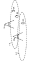
- FIG. 1 is a diagram illustrating an example of a communication system according to the present embodiment.
- the communication system in this embodiment includes base station apparatuses 1A and 1B and terminal apparatuses 2A, 2B and 2C.
- the coverage 1-1 is a range (communication area) in which the base station device 1A can be connected to the terminal device.
- the coverage 1-2 is a range (communication area) in which the base station device 1B can be connected to the terminal device.
- the terminal devices 2A and 2B are also referred to as the terminal device 2.
- the received signal at the terminal device 2 is A desired signal addressed to a device (also referred to as a first terminal device) and a signal addressed to a terminal device (also referred to as a second terminal device) that cause interference are included.
- the received signal in the terminal device 2A includes a desired signal transmitted from the base station device 1A to the own terminal device, a signal addressed to the terminal device 2B, and a signal addressed to the terminal device 2C transmitted from the base station device 1B. And an interference signal.
- the received signal in the terminal device 2B is an interference that is a desired signal addressed to the own terminal device transmitted from the base station device 1A, a signal addressed to the terminal device 2A and a signal addressed to the terminal device 2C transmitted from the base station device 1B. Signal.
- the base station apparatus may be a case where the terminal apparatus receives inter-user interference or another base station apparatus receives inter-cell interference by spatially multiplexing a plurality of terminal apparatuses. It is not limited to the communication system of FIG. Further, it is not necessary to receive inter-user interference and inter-cell interference at the same time, and both the case of receiving only inter-user interference and the case of receiving only inter-cell interference are included in the present invention.
- the following uplink physical channels are used in uplink wireless communication from the terminal apparatus 2 to the base station apparatus 1A.
- the uplink physical channel is used for transmitting information output from an upper layer.
- -PUCCH Physical Uplink Control Channel
- PUSCH Physical Uplink Shared Channel
- PRACH Physical Random Access Channel
- the PUCCH is used for transmitting uplink control information (Uplink Control Information: UCI).
- UCI Uplink Control Information
- the uplink control information includes ACK (a positive acknowledgement) or NACK (a negative acknowledgement) (ACK / NACK) for downlink data (downlink transport block, Downlink-Shared Channel: DL-SCH).
- ACK / NACK for downlink data is also referred to as HARQ-ACK and HARQ feedback.
- the uplink control information includes channel state information (Channel State Information: CSI) for the downlink. Further, the uplink control information includes a scheduling request (Scheduling Request: SR) used to request resources of an uplink shared channel (Uplink-Shared Channel: UL-SCH).
- the channel state information corresponds to a rank index RI that specifies a suitable spatial multiplexing number, a precoding matrix index PMI that specifies a suitable precoder, a channel quality index CQI that specifies a suitable transmission rate, and the like.
- the channel quality indicator CQI (hereinafter referred to as CQI value) may be a suitable modulation scheme (for example, QPSK, 16QAM, 64QAM, 256QAM, etc.) and code rate in a predetermined band (details will be described later). it can.
- the CQI value can be an index (CQI Index) determined by the change method and coding rate.
- the CQI value can be predetermined by the system.
- the rank index and the precoding quality index can be determined in advance by the system.
- the rank index and the precoding matrix index can be indexes determined by the spatial multiplexing number and precoding matrix information.
- the values of the rank index, the precoding matrix index, and the channel quality index CQI are collectively referred to as CSI values.
- the PUSCH is used for transmitting uplink data (uplink transport block, UL-SCH). Moreover, PUSCH may be used to transmit ACK / NACK and / or channel state information together with uplink data. Moreover, PUSCH may be used in order to transmit only uplink control information.
- PUSCH is used to transmit an RRC message.
- the RRC message is information / signal processed in a radio resource control (Radio-Resource-Control: -RRC) layer.
- the PUSCH is used to transmit a MAC CE (Control Element).
- the MAC CE is information / signal processed (transmitted) in the medium access control (MAC) layer.
- the power headroom may be included in the MAC CE and reported via PUSCH. That is, the MAC CE field may be used to indicate the power headroom level.
- PRACH is used to transmit a random access preamble.
- an uplink reference signal (Uplink Reference Signal: UL SRS) is used as an uplink physical signal.
- the uplink physical signal is not used for transmitting information output from the upper layer, but is used by the physical layer.
- the uplink reference signal includes DMRS (Demodulation Reference Signal) and SRS (Sounding Reference Signal).
- DMRS is related to transmission of PUSCH or PUCCH.
- base station apparatus 1A uses DMRS to perform propagation channel correction for PUSCH or PUCCH.
- SRS is not related to PUSCH or PUCCH transmission.
- the base station apparatus 1A uses SRS to measure the uplink channel state.
- the following downlink physical channels are used in downlink wireless communication from the base station apparatus 1A to the terminal apparatus 2.
- the downlink physical channel is used for transmitting information output from an upper layer.
- PBCH Physical Broadcast Channel
- PCFICH Physical Control Format Indicator Channel
- PHICH Physical Hybrid automatic repeat request Indicator Channel: HARQ instruction channel
- PDCCH Physical Downlink Control Channel
- EPDCCH Enhanced Physical Downlink Control Channel
- PDSCH Physical Downlink Shared Channel
- the PBCH is used for broadcasting a master information block (Master Information Block: MIB, Broadcast Channel: BCH) commonly used in the terminal device 2.
- MIB Master Information Block
- BCH Broadcast Channel
- PCFICH is used for transmitting information indicating a region (for example, the number of OFDM symbols) used for transmission of PDCCH.
- PHICH is used to transmit ACK / NACK for uplink data (transport block, codeword) received by the base station apparatus 1A. That is, PHICH is used to transmit a HARQ indicator (HARQ feedback) indicating ACK / NACK for uplink data. ACK / NACK is also referred to as HARQ-ACK.
- the terminal device 2 notifies the received ACK / NACK to the higher layer.
- ACK / NACK is ACK indicating that the data has been correctly received, NACK indicating that the data has not been correctly received, and DTX indicating that there is no corresponding data. Further, when there is no PHICH for the uplink data, the terminal device 2 notifies the upper layer of ACK.
- DCI Downlink Control Information
- a plurality of DCI formats are defined for transmission of downlink control information. That is, fields for downlink control information are defined in the DCI format and mapped to information bits.
- a DCI format 1A used for scheduling one PDSCH (transmission of one downlink transport block) in one cell is defined as a DCI format for the downlink.
- the DCI format for the downlink includes information on PDSCH resource allocation, information on MCS (Modulation and Coding Scheme) for PDSCH, and downlink control information such as a TPC command for PUCCH.
- the DCI format for the downlink is also referred to as a downlink grant (or downlink assignment).
- DCI format 0 used for scheduling one PUSCH (transmission of one uplink transport block) in one cell is defined.
- the DCI format for uplink includes information on PUSCH resource allocation, information on MCS for PUSCH, and uplink control information such as TPC command for PUSCH.
- the DCI format for the uplink is also referred to as uplink grant (or uplink assignment).
- the DCI format for uplink can be used to request downlink channel state information (CSI: “Channel State Information”, also referred to as reception quality information).
- the channel state information includes a rank index RI (Rank Indicator) that designates a suitable spatial multiplexing number, a precoding matrix indicator PMI (Precoding Matrix Indicator) that designates a suitable precoder, and a channel quality indicator CQI (Specify a suitable transmission rate).
- rank index RI Rank Indicator
- PMI Precoding Matrix Indicator
- CQI Specific Transmission Rate
- Channel Quality Indicator Channel Quality Indicator
- the DCI format for the uplink can be used for setting indicating an uplink resource for mapping a channel state information report (CSI feedback report) that the terminal apparatus feeds back to the base station apparatus.
- the channel state information report can be used for setting indicating an uplink resource that periodically reports channel state information (Periodic CSI).
- the channel state information report can be used for mode setting (CSI report mode) for periodically reporting the channel state information.
- the channel state information report can be used for setting indicating an uplink resource for reporting irregular channel state information (Aperiodic CSI).
- the channel state information report can be used for mode setting (CSI report mode) for reporting the channel state information irregularly.
- the base station devices 1A and 1B can set either the periodic channel state information report or the irregular channel state information report.
- the base station apparatuses 1A and 1B can also set both the regular channel state information report and the irregular channel state information report.
- the DCI format for the uplink can be used for setting indicating the type of channel state information report that the terminal apparatus feeds back to the base station apparatus.
- Types of channel state information reports include wideband CSI (for example, Wideband CQI) and narrowband CSI (for example, Subband CQI).
- the DCI format for the uplink it can be used for mode setting including types of the periodic channel state information report or the irregular channel state information report and the channel state information report. For example, a mode for reporting irregular channel state information and wideband CSI, a mode for reporting irregular channel state information and reporting narrowband CSI, an irregular channel state information report, and broadband CSI and narrowband CSI Mode, periodic channel state information report and wideband CSI report mode, periodic channel state information report and narrowband CSI mode, periodic channel state information report and wideband CSI and narrowband CSI There is a mode to report.
- the terminal device 2 When the PDSCH resource is scheduled using the downlink assignment, the terminal device 2 receives the downlink data on the scheduled PDSCH. Moreover, when the PUSCH resource is scheduled using the uplink grant, the terminal device 2 transmits uplink data and / or uplink control information using the scheduled PUSCH.
- the PDSCH is used to transmit downlink data (downlink transport block, DL-SCH).
- the PDSCH is used to transmit a system information block type 1 message.
- the system information block type 1 message is cell specific (cell specific) information.
- PDSCH is used to transmit a system information message.
- the system information message includes a system information block X other than the system information block type 1.
- the system information message is cell specific (cell specific) information.
- PDSCH is used to transmit an RRC message.
- the RRC message transmitted from the base station apparatus 1A may be common to a plurality of terminal apparatuses 2 in the cell.
- the RRC message transmitted from the base station device 1A may be a message dedicated to a certain terminal device 2 (also referred to as dedicated signaling).
- user device specific (user device specific) information is transmitted to a certain terminal device 2 using a dedicated message.
- the PDSCH is used to transmit the MAC CE.
- the RRC message and / or MAC CE is also referred to as higher layer signaling.
- PDSCH can be used to request downlink channel state information.
- the PDSCH can be used to transmit an uplink resource that maps a channel state information report (CSI feedback report) that the terminal device feeds back to the base station device.
- CSI feedback report can be used for setting indicating an uplink resource that periodically reports channel state information (Periodic CSI).
- the channel state information report can be used for mode setting (CSI report mode) for periodically reporting the channel state information.
- the types of downlink channel state information reports include wideband CSI (for example, Wideband CSI) and narrowband CSI (for example, Subband CSI).
- the broadband CSI calculates one channel state information for the system band of the cell.
- the narrowband CSI the system band is divided into predetermined units, and one channel state information is calculated for the division.
- a synchronization signal (Synchronization signal: SS) and a downlink reference signal (Downlink Signal: DL RS) are used as downlink physical signals.
- the downlink physical signal is not used to transmit information output from the upper layer, but is used by the physical layer.
- the synchronization signal is used by the terminal device 2 to synchronize the downlink frequency domain and time domain. Further, the downlink reference signal is used by the terminal device 2 for performing channel correction of the downlink physical channel. For example, the downlink reference signal is used by the terminal device 2 to calculate downlink channel state information.
- the downlink reference signal includes CRS (Cell-specific Reference Signal: UE-specific reference signal), URS (UE-specific Reference Signal: UE-specific reference signal) related to PDSCH, DMRS (Demodulation Reference) related to EPDCCH. Signal), NZP CSI-RS (Non-Zero Power Chanel State Information Reference Signal), ZP CSI-RS (Zero Power Chanel State Information Reference Signal).
- CRS Cell-specific Reference Signal: UE-specific reference signal
- URS UE-specific Reference Signal: UE-specific reference signal
- DMRS Demodulation Reference
- NZP CSI-RS Non-Zero Power Chanel State Information Reference Signal
- ZP CSI-RS Zero Power Chanel State Information Reference Signal
- CRS is transmitted in the entire band of the subframe, and is used to demodulate PBCH / PDCCH / PHICH / PCFICH / PDSCH.
- the URS associated with the PDSCH is transmitted in subframes and bands used for transmission of the PDSCH associated with the URS, and is used to demodulate the PDSCH associated with the URS.
- DMRS related to EPDCCH is transmitted in subframes and bands used for transmission of EPDCCH related to DMRS.
- DMRS is used to demodulate the EPDCCH with which DMRS is associated.
- NZP CSI-RS resources are set by the base station apparatus 1A.
- the terminal device 2 performs signal measurement (channel measurement) using NZP CSI-RS.
- the resource of ZP CSI-RS is set by the base station apparatus 1A.
- the base station apparatus 1A transmits ZP CSI-RS with zero output.
- the terminal device 2 measures interference in a resource supported by NZP CSI-RS.
- ZP CSI-RS resources are set by the base station device 1A.
- the base station apparatus 1B transmits ZP CSI-RS with zero output. That is, the base station device 1A does not transmit the ZP CSI-RS.
- the base station apparatus 1B does not transmit PDSCH and EPDCCH using resources set by ZP CSI-RS.
- the terminal device 2C can measure interference in a resource corresponding to NZP CSI-RS in a certain cell.
- MBSFN Multimedia Broadcast Multicast Service Single Frequency Network
- the MBSFN RS is used for PMCH demodulation.
- PMCH is transmitted through an antenna port used for transmission of MBSFN RS.
- the downlink physical channel and the downlink physical signal are collectively referred to as a downlink signal.
- the uplink physical channel and the uplink physical signal are collectively referred to as an uplink signal.
- the downlink physical channel and the uplink physical channel are collectively referred to as a physical channel.
- the downlink physical signal and the uplink physical signal are collectively referred to as a physical signal.
- BCH, UL-SCH and DL-SCH are transport channels.
- a channel used in the MAC layer is referred to as a transport channel.
- the unit of the transport channel used in the MAC layer is also referred to as a transport block (Transport Block: TB) or a MAC PDU (Protocol Data Unit).
- the transport block is a unit of data that is delivered (delivered) by the MAC layer to the physical layer. In the physical layer, the transport block is mapped to a code word, and an encoding process or the like is performed for each code word.
- the terminal device can have a function of removing or suppressing inter-user interference and inter-cell interference.
- a technique is considered as NAICS (Network Assisted Interference Cancellation and Suppression) by 3GPP (3rd Generation Partnership Project).
- NAICS Network Assisted Interference Cancellation and Suppression
- a base station apparatus transmits NAICS assist information (also referred to as support information or first support information) used by a terminal apparatus for handling, removing, or suppressing an interference signal.
- the terminal device receives the NAICS assist information, detects a parameter for removing or suppressing the interference signal based on the NAICS assist information, and removes or suppresses the interference signal using the parameter.
- the NAICS assist information includes cell ID, number of CRS antenna ports, MBSFN subframe setting list, PB, virtual cell ID (virtual cell ID), scrambling identity (nSCID), PA, transmission mode, QCL information (quasi co-location information), ZP / NZP CSI-RS configuration, PDSCH start position (PDSCH starting position), TDD UL / DL configuration, precoding matrix index / rank index, modulation scheme, and part or all of resource allocation information.
- PA is a power ratio of PDSCH and CRS in an OFDM symbol in which CRS is not arranged.
- PB represents the power ratio of PDSCH in the OFDM symbol in which CRS is not arranged and PDSCH in the OFDM symbol in which CRS is not arranged.
- the QCL information is information related to the QCL for a predetermined antenna port, a predetermined signal, or a predetermined channel. In two antenna ports, if the long-term characteristics of the channel carrying the symbol on one antenna port can be inferred from the channel carrying the symbol on the other antenna port, those antenna ports are QCL It is called. Long interval characteristics include delay spread, Doppler spread, Doppler shift, average gain and / or average delay. That is, when the two antenna ports are QCL, the terminal device can be regarded as having the same long section characteristics at the antenna ports.
- the NAICS function includes MU-MIMO (Multi-user Multiple Input Multiple Output) that spatially multiplexes signals addressed to a plurality of terminal devices on the base station device side or non-orthogonal access
- the base station device Information regarding non-orthogonal access can also be included in the NAICS assist information.
- Inter-user interference in MU-MIMO or non-orthogonal access is also called intra-cell interference.
- a different transmission power is assigned to a signal addressed to each terminal device, and when the transmission power or reception power of a signal addressed to another terminal device (that is, an interference signal) is larger than the signal addressed to the terminal device itself
- the device removes or suppresses interference signals due to NAICS.
- the transmission power or reception power of the interference signal is smaller than that of the signal addressed to the own terminal device, the interference signal is not necessarily removed or suppressed by NAICS (may be performed).
- Information on MU-MIMO and non-orthogonal access is, for example, information on whether the base station apparatus supports MU-MIMO and non-orthogonal access (for example, transmission mode) and transmission power.
- one value (candidate) may be set for each of the parameters included in the NAICS assist information, or a plurality of values (candidates) may be set.
- the terminal device interprets that the parameter indicates a value that may be set by the base station device that causes interference, and sets the interference signal from the multiple values. Detect the parameters that are being used.
- the NAICS assist information may indicate information of another base station apparatus or may indicate information of its own base station apparatus.
- the NAICS assist information is used by the terminal device to handle, remove, or suppress interference from the PDSCH to other terminal devices when demodulating the PDSCH for the terminal device. Therefore, the NAICS assist information is also referred to as PDSCH interference assist information or PDSCH assist information.
- the NAICS assist information includes at least information related to mapping of PDSCH resource elements to other terminal apparatuses.
- the NAICS assist information may be used when performing various measurements.
- the measurement includes RRM (Radio Resource Management) measurement, RLM (Radio Link Monitoring) measurement, and CSI (Channel State Information) measurement.
- the terminal device detects (identifies) PDSCH interference based on the set NAICS assist information, and reduces the detected PDSCH interference.
- the NAICS assist information may include quasi-static control information with a relatively long update frequency, and may not include dynamic control information with a relatively low update frequency.
- the quasi-static control information includes cell ID, number of CRS antenna ports, MBSFN subframe pattern, PB, virtual cell ID (virtual cell ID), scrambling identity (nSCID), PA, transmission mode, QCL information (quasi co- location information), ZP / NZP CSI-RS configuration, PDSCH starting position, TDD UL / DL configuration, etc.
- the dynamic control information includes a precoding matrix index / rank index, a modulation scheme, resource allocation information, and the like.
- the NAICS assist information can be regarded as information for indicating a plurality of PDSCH interference candidates.
- the terminal device can perform blind detection in an attempt to detect PDSCH interference candidates that can be recognized based on NAICS assist information in order.
- the terminal device can reduce interference by PDSCH with respect to other terminal devices based on the parameters detected from the NAICS assist information, a signal addressed to the terminal device can be obtained with high accuracy.
- the NAICS assist information indicates a plurality of candidates, the influence on the scheduling of the base station apparatus can be reduced.
- the terminal device may perform blind detection on a parameter that has not been received as assist information.
- linear detection or non-linear detection can be performed.
- the linear detection can be performed in consideration of the channel of the desired signal addressed to the own terminal device and the channel of the interference signal addressed to the other terminal device.
- Such linear detection is also called ELMMSE-IRC (Enhanced-Linear-Minimum-Mean-Square-Error-Interference-Rejection-Combining).
- interference canceller or maximum likelihood detection can be performed.
- the base station apparatus can transmit the NAICS assist information in a list as a NAICS assist information list.
- the NAICS assist information list can include at least one NAICS assist information.
- the NAICS assist information list can be transmitted as neighboring cell NAICS information (also referred to as first interference information).
- the NAICS assist information list may be referred to as a PDSCH assist information list.
- the neighbor cell NAICS information may be referred to as neighbor cell PDSCH information.
- the terminal apparatus uses the CRS assist information (also referred to as second support information) transmitted from the base station apparatus using an upper layer signal, Interference received from the CRS of the base station apparatus can be reduced.
- the CRS assist information is information on other base station apparatuses, and includes a cell ID, the number of CRS antenna ports, and an MBSFN subframe setting list.
- the CRS assist information is sent as a list by the CRS assist information list.
- the CRS assist information list includes at least one CRS assist information.
- the CRS assist information list is transmitted as neighboring cell CRS information (also referred to as second interference information).
- the CRS assist information is used by the terminal device for handling, removing, or suppressing interference from the CRS of another cell (neighboring cell) when demodulating the PDSCH for the terminal device.
- the CRS assist information may be used when performing various measurements.
- the measurement includes RRM (Radio Resource Management) measurement, RLM (Radio Link Monitoring) measurement, and CSI (Channel State Information) measurement.
- the NAICS assist information can be used not only when the terminal apparatus handles not only PDSCH interference but also CRS interference and other channel interference.
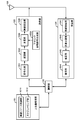
- FIG. 2 is a schematic block diagram showing the configuration of the base station apparatus 1A in the present embodiment.
- the base station apparatus 1A includes an upper layer processing unit 101, a control unit 102, a transmission unit 103, a reception unit 104, and a transmission / reception antenna 105.
- the upper layer processing unit 101 includes a radio resource control unit 1011 and a scheduling unit 1012.
- the transmission unit 103 includes an encoding unit 1031, a modulation unit 1032, a downlink reference signal generation unit 1033, a multiplexing unit 1034, and a wireless transmission unit 1035.
- the reception unit 104 includes a wireless reception unit 1041, a demultiplexing unit 1042, a demodulation unit 1043, and a decoding unit 1044.
- the upper layer processing unit 101 includes a medium access control (Medium Access Control: MAC) layer, a packet data integration protocol (Packet Data Convergence Protocol: PDCP) layer, a radio link control (Radio Link Control: RLC) layer, a radio resource control (Radio) Resource (Control: RRC) layer processing.
- MAC Medium Access Control
- PDCP Packet Data Convergence Protocol
- RLC Radio Link Control
- RRC radio resource control
- upper layer processing section 101 generates information necessary for controlling transmission section 103 and reception section 104 and outputs the information to control section 102.
- the upper layer processing unit 101 receives information related to the terminal device such as the function (UE capability) of the terminal device from the terminal device. In other words, the terminal apparatus transmits its own function to the base station apparatus using an upper layer signal.
- the function of the terminal device can include a parameter indicating whether NAICS is supported.
- the terminal apparatus can transmit to the base station apparatus by using individual parameters whether each function is supported. For example, when two functions of PDSCH interference handling and CRS interference handling are included as NAICS, the terminal apparatus indicates a signal indicating whether PDSCH interference handling is supported, and indicates whether CRS interference handling is supported. The signal can be transmitted to the base station apparatus.
- NAICS includes a function for removing or suppressing inter-user interference such as MU-MIMO or non-orthogonal access
- a signal indicating whether inter-user interference handling is supported is transmitted to the base station apparatus. can do.
- Inter-user interference handling may be a function included in PDSCH interference handling. That is, it can be assumed that a terminal device that supports PDSCH interference handling has a function of handling inter-cell interference and inter-user interference.
- information on a terminal device includes information indicating whether the terminal device supports a predetermined function, or information indicating that the terminal device has introduced a predetermined function and has completed a test.
- whether or not to support a predetermined function includes whether or not installation and testing for the predetermined function have been completed.
- the terminal device transmits information (parameters) indicating whether the predetermined function is supported.
- the terminal device does not transmit information (parameter) indicating whether or not the predetermined device is supported. That is, whether or not to support the predetermined function is notified by whether or not information (parameter) indicating whether or not to support the predetermined function is transmitted. Note that information (parameter) indicating whether or not to support a predetermined function may be notified using 1 bit of 1 or 0.
- the upper layer processing unit 101 determines whether or not to set NAICS assist information and whether or not to set CRS assist information.
- the base station apparatus can determine whether or not to set NAICS assist information from the function of the terminal apparatus.
- the radio resource control unit 1011 generates or acquires downlink data (transport block), system information, RRC message, MAC CE, and the like arranged on the downlink PDSCH from the upper node.
- the radio resource control unit 1011 outputs downlink data to the transmission unit 103 and outputs other information to the control unit 102.
- the radio resource control unit 1011 manages various setting information of the terminal device 2.
- This setting information can include setting information of a terminal device that causes interference.
- the setting information of the terminal device that causes interference can be acquired from the setting information of the own terminal device.
- the setting information of the base station apparatus that causes interference can be included.
- the scheduling unit 1012 determines the frequency and subframe to which the physical channels (PDSCH and PUSCH) are allocated, the coding rate and modulation scheme (or MCS) of the physical channels (PDSCH and PUSCH), transmission power, and the like.
- the scheduling unit 1012 outputs the determined information to the control unit 102.
- the scheduling unit 1012 generates information used for physical channel (PDSCH and PUSCH) scheduling based on the scheduling result.
- the scheduling unit 1012 outputs the generated information to the control unit 102.
- the scheduling unit 1012 schedules the terminal device 2A and the terminal device 2B to the same resource. In this embodiment, for the sake of simplicity, the same resource is used. However, different resources may be scheduled. Note that scheduling can be performed in cooperation with the base station apparatus 1B.
- the control unit 102 generates a control signal for controlling the transmission unit 103 and the reception unit 104 based on the information input from the higher layer processing unit 101.
- the control unit 102 generates downlink control information based on the information input from the higher layer processing unit 101 and outputs the downlink control information to the transmission unit 103.
- the transmission unit 103 generates a downlink reference signal according to the control signal input from the control unit 102, and encodes the HARQ indicator, downlink control information, and downlink data input from the higher layer processing unit 101. Then, PHICH, PDCCH, EPDCCH, PDSCH, and downlink reference signal are multiplexed, and the signal is transmitted to the terminal apparatus 2 via the transmission / reception antenna 105.
- the encoding unit 1031 uses a predetermined encoding method such as block encoding, convolutional encoding, and turbo encoding for the HARQ indicator, downlink control information, and downlink data input from the higher layer processing unit 101. Encoding is performed using the encoding method determined by the radio resource control unit 1011.
- the modulation unit 1032 converts the encoded bits input from the encoding unit 1031 into BPSK (Binary Phase Shift Shift Keying), QPSK (quadrature Phase Shift Shift Keying), 16 QAM (quadrature Amplitude Modulation), 64 QAM, 256 QAM, and the like. Or it modulates with the modulation system which the radio
- the downlink reference signal generation unit 1033 is a sequence that is known by the terminal device 2 and is obtained by a predetermined rule based on a physical cell identifier (Physical cell identity: PCI, cell ID) for identifying the base station device 1A. As a downlink reference signal.
- a physical cell identifier Physical cell identity: PCI, cell ID
- the multiplexing unit 1034 multiplexes the modulated modulation symbol of each channel, the generated downlink reference signal, and downlink control information. That is, multiplexing section 1034 arranges the modulated modulation symbol of each channel, the generated downlink reference signal, and downlink control information in the resource element.
- the radio transmission unit 1035 generates an OFDM symbol by performing inverse fast Fourier transform (Inverse Fourier Transform: IFFT) on the multiplexed modulation symbol and the like, and adds a cyclic prefix (cyclic prefix: CP) to the OFDM symbol.
- IFFT inverse fast Fourier transform
- CP cyclic prefix
- the receiving unit 104 separates, demodulates, and decodes the received signal received from the terminal device 2 via the transmission / reception antenna 105 according to the control signal input from the control unit 102, and outputs the decoded information to the upper layer processing unit 101. .
- the radio reception unit 1041 converts an uplink signal received via the transmission / reception antenna 105 into a baseband signal by down-conversion, removes unnecessary frequency components, and amplifies the signal level so that the signal level is properly maintained.
- the level is controlled, quadrature demodulation is performed based on the in-phase component and the quadrature component of the received signal, and the analog signal that has been demodulated is converted into a digital signal.
- the wireless reception unit 1041 removes a portion corresponding to the CP from the converted digital signal.
- Radio receiving section 1041 performs fast Fourier transform (FFT) on the signal from which CP has been removed, extracts a signal in the frequency domain, and outputs the signal to demultiplexing section 1042.
- FFT fast Fourier transform
- the demultiplexing unit 1042 demultiplexes the signal input from the wireless reception unit 1041 into signals such as PUCCH, PUSCH, and uplink reference signal. This separation is performed based on radio resource allocation information included in the uplink grant that is determined in advance by the radio resource control unit 1011 by the base station apparatus 1A and notified to each terminal apparatus 2.
- the demultiplexing unit 1042 compensates for the propagation paths of the PUCCH and PUSCH. Further, the demultiplexing unit 1042 demultiplexes the uplink reference signal.
- the demodulator 1043 performs inverse discrete Fourier transform (Inverse Discrete Fourier Transform: IDFT) on the PUSCH, acquires modulation symbols, and pre-modulates BPSK, QPSK, 16QAM, 64QAM, 256QAM, etc. for each of the PUCCH and PUSCH modulation symbols.
- IDFT inverse discrete Fourier transform
- the received signal is demodulated by using a modulation method determined or notified in advance by the own device to each of the terminal devices 2 using an uplink grant.
- the decoding unit 1044 uses the coding rate of the demodulated PUCCH and PUSCH in a predetermined encoding method, the predetermined coding method, or the coding rate notified by the own device to the terminal device 2 using the uplink grant. Decoding is performed, and the decoded uplink data and uplink control information are output to the upper layer processing section 101. When PUSCH is retransmitted, decoding section 1044 performs decoding using the coded bits held in the HARQ buffer input from higher layer processing section 101 and the demodulated coded bits.
- FIG. 3 is a schematic block diagram showing the configuration of the terminal device 2 in the present embodiment.
- the terminal device 2 includes an upper layer processing unit 201, a control unit 202, a transmission unit 203, a reception unit 204, a channel state information generation unit 205, and a transmission / reception antenna 206.
- the upper layer processing unit 201 includes a radio resource control unit 2011 and a scheduling information interpretation unit 2012.
- the transmission unit 203 includes an encoding unit 2031, a modulation unit 2032, an uplink reference signal generation unit 2033, a multiplexing unit 2034, and a wireless transmission unit 2035.
- the reception unit 204 includes a wireless reception unit 2041, a demultiplexing unit 2042, and a signal detection unit 2043.
- the upper layer processing unit 201 outputs uplink data (transport block) generated by a user operation or the like to the transmission unit 203. Further, the upper layer processing unit 201 includes a medium access control (Medium Access Control: MAC) layer, a packet data integration protocol (Packet Data Convergence Protocol: PDCP) layer, a radio link control (Radio Link Control: RLC) layer, and a radio resource control. Process the (Radio Resource Control: RRC) layer.
- Medium Access Control Medium Access Control: MAC
- PDCP Packet Data Convergence Protocol
- RLC Radio Link Control
- RRC Radio Resource Control
- the upper layer processing unit 201 outputs information indicating the function of the terminal device supported by the own terminal device to the transmission unit 203.
- the radio resource control unit 2011 manages various setting information of the own terminal device. Also, the radio resource control unit 2011 generates information arranged in each uplink channel and outputs the information to the transmission unit 203.
- the radio resource control unit 2011 acquires setting information regarding CSI feedback transmitted from the base station apparatus, and outputs the setting information to the control unit 202.
- the scheduling information interpretation unit 2012 interprets the downlink control information received via the reception unit 204 and determines scheduling information.
- the scheduling information interpretation unit 2012 generates control information for controlling the reception unit 204 and the transmission unit 203 based on the scheduling information, and outputs the control information to the control unit 202.
- the control unit 202 generates a control signal for controlling the receiving unit 204, the channel state information generating unit 205, and the transmitting unit 203 based on the information input from the higher layer processing unit 201.
- the control unit 202 controls the reception unit 204 and the transmission unit 203 by outputting the generated control signal to the reception unit 204, the channel state information generation unit 205, and the transmission unit 203.
- the control unit 202 controls the transmission unit 203 to transmit the CSI generated by the channel state information generation unit 205 to the base station apparatus.
- the receiving unit 204 separates, demodulates, and decodes the received signal received from the base station apparatus 1A via the transmission / reception antenna 206 according to the control signal input from the control unit 202, and sends the decoded information to the upper layer processing unit 201. Output.
- the receiving unit 204 includes a reference signal (also referred to as a first reference signal) corresponding to the base station apparatus 1A included in the received signal, and a reference signal (second reference) based on interference information set by the base station apparatus 1A. (Also referred to as a signal) and output to the channel state information generation unit 205.
- the radio reception unit 2041 converts a downlink signal received via the transmission / reception antenna 206 into a baseband signal by down-conversion, removes unnecessary frequency components, and increases the amplification level so that the signal level is appropriately maintained. , And quadrature demodulation based on the in-phase and quadrature components of the received signal, and converting the quadrature demodulated analog signal into a digital signal.
- the wireless reception unit 2041 removes a portion corresponding to CP from the converted digital signal, performs fast Fourier transform on the signal from which CP is removed, and extracts a frequency domain signal.
- the demultiplexing unit 2042 separates the extracted signal into PHICH, PDCCH, EPDCCH, PDSCH, and downlink reference signal. Further, the demultiplexing unit 2042 compensates for the PHICH, PDCCH, and EPDCCH channels based on the channel estimation value of the desired signal obtained from the channel measurement, detects downlink control information, and sends it to the control unit 202. Output. In addition, control unit 202 outputs PDSCH and the channel estimation value of the desired signal to signal detection unit 2043.
- the signal detection unit 2043 detects a signal using the PDSCH and the channel estimation value, and outputs the signal to the higher layer processing unit 201.
- signal detection is performed by removing or suppressing the interference signal.
- the removal or suppression of the interference signal for example, linear detection considering the channel estimation value of the interference signal, or interference cancellation or maximum likelihood detection considering the channel estimation value of the interference signal and the modulation method are performed.
- the signal detection unit 2043 detects (identifies) parameters necessary for interference channel estimation and / or demodulation of the interference signal. For parameters for which a plurality of values are set in the NAICS assist information, a plurality of values are used as candidates, and the values set in the interference signal are blind-detected. In addition, for parameters that are not set in the NAICS assist information, values that may be set in the system may be candidates, and values set in the interference signal may be detected blindly. The signal detection unit 2043 removes or suppresses the PDSCH / CRS interference signal using the detected parameter.
- detecting the parameter of the interference signal increases the amount of computation of the terminal device, so it is desirable to detect only necessary information.
- Information necessary for demodulation can be determined by the parameters of the signal addressed to the terminal device itself and some parameters set in the interference signal.
- the terminal device when the number of layers included in the downlink control information transmitted from the serving cell is 3 or more, the terminal device does not remove or suppress the interference signal based on the NAICS assist information even if the NAICS assist information is set. be able to. At this time, since the parameter of the interference signal is not blind-detected based on the NAICS assist information, the calculation amount of the terminal device can be reduced.
- the terminal apparatus does not assume MU-MIMO. That is, the interference signal is removed or suppressed based on NAICS assist information regarding a physical cell ID different from the physical cell ID of the serving cell.
- NAICS assist information related to the same physical cell ID as that of the serving cell can be excluded from the candidates, so that the amount of computation of the terminal device can be reduced.
- the terminal apparatus does not assume MU-MIMO, and the terminal apparatus does not remove or suppress the interference signal based on NAICS assist information. Therefore, the calculation amount of the terminal device can be reduced.
- the terminal device does not assume TM1, TM2, TM3, TM4, and TM6 among the transmission modes included in the NAICS assist information. That is, the transmission mode included in the NAICS assist information is limited to the DMRS-based transmission mode.
- the DMRS-based transmission mode is, for example, TM8 / 9/10. In this case, the terminal device can limit the antenna port number to 7 or 8 interference signals.
- the terminal apparatus removes or suppresses the interference signal assuming MU-MIMO.
- the terminal device can perform blind detection assuming that the antenna port number of the interference signal is 7 or 8.
- the terminal device can determine that MU-MIMO is being performed, it can remove or suppress the interference signal assuming MU-MIMO.
- the terminal apparatus determines that the MU-MIMO is performed, it is not necessary to perform blind detection on at least a cell-specific parameter, and the amount of calculation of the terminal apparatus can be reduced.
- Cell-specific parameters are, for example, QCL information, ZP / NZP CSI-RS configuration, PDSCH start position, TDD UL / DL configuration, and the like.
- the terminal device As a method for determining whether or not the terminal device is MU-MIMO, for example, it is possible to know that the terminal device is MU-MIMO by blind detection of some of the parameters of the interference signal.
- the parameters necessary for the terminal device to determine whether MU-MIMO is used are less than those required to eliminate or suppress inter-cell interference. Therefore, if it can be determined that MU-MIMO is used, the amount of computation is reduced. Can be reduced.
- the terminal device can determine from an initial value of a pseudo-random sequence corresponding to a terminal-specific reference signal associated with the PDSCH.
- the initial value c init of the pseudorandom sequence corresponding to the terminal-specific reference signal associated with the PDSCH is expressed by the following equation (1).
- n s denotes a slot number within a radio frame.
- n ID (i) is also referred to as a first variable.
- the terminal device has a terminal-specific reference associated with the PDSCH assumed based on the value of the first variable constituting the initial value of the pseudo-random sequence corresponding to the terminal-specific reference signal associated with the PDSCH of the serving cell and the NAICS assist information.
- the interference signal can be removed or suppressed assuming MU-MIMO.
- the terminal apparatus also includes an initial value of a pseudo-random sequence corresponding to a terminal-specific reference signal associated with the PDSCH of the serving cell and a pseudo-random sequence corresponding to a terminal-specific reference signal associated with the PDSCH assumed based on the NAICS assist information. If the initial values are the same, interference signals can be removed or suppressed assuming MU-MIMO.
- the terminal device corresponds to a terminal-specific reference signal associated with the PDSCH assumed based on the NAICS assist information when the transmission mode of the terminal device is TM10 and the virtual cell ID is not set in the upper layer.
- the terminal device can remove or suppress the interference signal assuming MU-MIMO.
- Another method for determining whether the terminal apparatus is MU-MIMO is that the base station apparatus transmits information indicating that the terminal apparatus is MU-MIMO or intra-cell interference to the terminal apparatus.
- the terminal device is MU-MIMO.
- the base station apparatus can signal whether the terminal apparatus is MU-MIMO using a higher layer signal or a physical layer signal (for example, downlink control information).
- the base station apparatus When the base station apparatus performs signaling to the terminal apparatus using an upper layer signal, the base station apparatus individually sets NAICS assist information corresponding to inter-cell interference and / or NAICS assist information corresponding to MU-MIMO. In this case, the terminal apparatus removes or suppresses the interference signal based on NAICS assist information corresponding to inter-cell interference and / or MU-MIMO.
- the base station device When the base station device signals to the terminal device whether it is MU-MIMO with a physical layer signal and the transmission mode of the terminal device is TM8 / 9, or the virtual cell ID is set in TM10 If not, the interference signal parameter is blind detected assuming MU-MIMO.
- the interference signal parameter is blind detected assuming MU-MIMO.
- blind detection is possible even when there is no assist information, because the antenna port is different between users, the scrambling identity is different, and the antenna port and scrambling identity are different. is there. Therefore, for example, if there is 1-bit signaling indicating whether or not MU-MIMO is performed in the physical layer signal from the base station apparatus, the terminal apparatus can perform inter-user interference even if NAICS assist information is not set. Can be removed or suppressed.
- the base station device signals to the terminal device whether or not MU-MIMO is performed using a physical layer signal
- the terminal device Assumes that the virtual cell ID is also set in TM10 for the interference signal, and other parameters can be blindly detected.
- the first variable constituting the initial value of the pseudo-random sequence of the terminal-specific reference signal associated with the PDSCH addressed to the terminal device and the pseudo-random sequence of the terminal-specific reference signal associated with the PDSCH of the interference signal It can be assumed that the first variable constituting the initial value is the same.
- the terminal device can determine whether or not non-orthogonal access is performed, it can remove or suppress the interference signal assuming non-orthogonal access. For example, when different transmission power is allocated between multiplexed terminal apparatuses, when the transmission power of the interference signal is larger than the transmission power of the signal addressed to the own terminal apparatus, the interference signal is removed by NAICS. Alternatively, since suppression is necessary, the terminal device must detect a parameter set in the interference signal. On the other hand, if the transmission power of the interference signal is smaller than the transmission power of the signal destined for the terminal device, it is not always necessary to remove or suppress the interference signal by NAICS, so the parameter set in the interference signal is detected. It is not necessary. In this case, the calculation amount of the terminal device can be reduced.
- the base station device can communicate in a transmission mode corresponding to non-orthogonal access or in a DCI format corresponding to non-orthogonal access.
- the DCI format corresponding to non-orthogonal access includes at least information regarding power control.
- the information related to power control is, for example, the power difference between the transmission power addressed to the terminal device and the transmission power of the interference signal, and the power control information of the interference signal.
- a predetermined power offset value is set in the power control information of the interference signal, and the positive / negative can be signaled by 1 bit.
- the power control information of the interference signal can be determined by blind detection. This blind detection may be performed based on assist information regarding power control.
- the terminal apparatus satisfies the conditions for determining MU-MIMO, compares the PA set for the signal addressed to itself with the PA set for the interference signal, and If the PA set for the signal is larger than the PA set for the interference signal, the interference signal is not removed or suppressed by NAICS. On the other hand, when the PA set in the signal addressed to the terminal device is smaller than the PA set in the interference signal, the interference signal is removed or suppressed by NAICS.
- the transmission unit 203 generates an uplink reference signal according to the control signal input from the control unit 202, encodes and modulates the uplink data (transport block) input from the higher layer processing unit 201, PUCCH, The PUSCH and the generated uplink reference signal are multiplexed and transmitted to the base station apparatus 1A via the transmission / reception antenna 206.
- the encoding unit 2031 performs encoding such as convolutional encoding and block encoding on the uplink control information input from the higher layer processing unit 201. Also, the coding unit 2031 performs turbo coding based on information used for PUSCH scheduling.
- the modulation unit 2032 modulates the coded bits input from the coding unit 2031 using a modulation scheme notified by downlink control information such as BPSK, QPSK, 16QAM, 64QAM, or a modulation scheme predetermined for each channel. .
- the uplink reference signal generation unit 2033 includes parameters for generating a physical cell identifier for identifying the base station apparatus 1A, a bandwidth for arranging the uplink reference signal, a cyclic shift notified by the uplink grant, and a DMRS sequence. Based on the value or the like, a sequence determined by a predetermined rule (formula) is generated.
- the multiplexing unit 2034 rearranges the PUSCH modulation symbols in parallel according to the control signal input from the control unit 202, and then performs a discrete Fourier transform (DFT). Also, the multiplexing unit 2034 multiplexes the PUCCH and PUSCH signals and the generated uplink reference signal for each transmission antenna port. That is, multiplexing section 2034 arranges the PUCCH and PUSCH signals and the generated uplink reference signal in the resource element for each transmission antenna port.
- DFT discrete Fourier transform
- the radio transmission unit 2035 performs inverse fast Fourier transform (Inverse Fast Fourier Transform: IFFT) on the multiplexed signal, performs SC-FDMA modulation, generates an SC-FDMA symbol, and generates the generated SC-FDMA symbol.
- IFFT inverse Fast Fourier Transform
- CP is added to baseband digital signal, baseband digital signal is converted to analog signal, excess frequency component is removed, converted to carrier frequency by up-conversion, power amplification, transmission / reception antenna It outputs to 206 and transmits.
- the program that operates in the base station apparatus and the terminal apparatus according to the present invention is a program (a program that causes a computer to function) that controls the CPU and the like so as to realize the functions of the above-described embodiments according to the present invention.
- Information handled by these devices is temporarily stored in the RAM at the time of processing, then stored in various ROMs and HDDs, read out by the CPU, and corrected and written as necessary.
- a recording medium for storing the program a semiconductor medium (for example, ROM, nonvolatile memory card, etc.), an optical recording medium (for example, DVD, MO, MD, CD, BD, etc.), a magnetic recording medium (for example, magnetic tape, Any of a flexible disk etc. may be sufficient.
- the processing is performed in cooperation with the operating system or other application programs.
- the functions of the invention may be realized.
- the program when distributing to the market, can be stored and distributed on a portable recording medium, or transferred to a server computer connected via a network such as the Internet.
- the storage device of the server computer is also included in the present invention.
- LSI which is typically an integrated circuit.
- Each functional block of the receiving apparatus may be individually chipped, or a part or all of them may be integrated into a chip. When each functional block is integrated, an integrated circuit controller for controlling them is added.
- the method of circuit integration is not limited to LSI, and may be realized by a dedicated circuit or a general-purpose processor.
- an integrated circuit based on the technology can also be used.
- the terminal device of the present invention is not limited to application to a mobile station device, but is a stationary or non-movable electronic device installed indoors or outdoors, such as AV equipment, kitchen equipment, cleaning / washing equipment Needless to say, it can be applied to air conditioning equipment, office equipment, vending machines, and other daily life equipment.
- the present invention is suitable for use in a terminal device, a base station device, and a communication method.
Abstract
効果的な干渉信号の知識や情報によって、演算量の増加を抑えつつ干渉を軽減することを目的とする。基地局装置から下りリンク制御情報を受信する受信部を備え、所定の送信モードの場合、下りリンク制御情報に含まれる下りリンク共有チャネルにおける自装置の送信電力と他装置の送信電力との間の電力オフセットに基づいて、自装置宛の下りリンク共有チャネルを復調する。また、電力オフセットの値に従って、干渉除去を行なうか否かを判断する。
Description
本発明は、端末装置、基地局装置および通信方法に関する。
3GPP(Third Generation Partnership Project)によるLTE(Long Term Evolution)、LTE-A(LTE-Advanced)やWiMAX(Worldwide Interoperability for Microwave Access)のような通信システムでは、基地局装置(基地局、送信局、送信点、下りリンク送信装置、上りリンク受信装置、送信アンテナ群、送信アンテナポート群、コンポーネントキャリア、eNodeB)或いは基地局装置に準じる送信局がカバーするエリアをセル(Cell)状に複数配置するセルラ構成とすることにより、通信エリアを拡大することができる。このセルラ構成において、隣接するセルまたはセクタ間で同一周波数を利用することで、周波数利用効率を向上させることができる。
しかし、このようなセルラ構成では、セル端(セルエッジ)領域またはセクタ端領域にいる端末装置(移動局装置、受信局、受信点、上りリンク送信装置、下りリンク受信装置、移動端末、受信アンテナ群、受信アンテナポート群、UE: User Equipment)は、他セルや他セクタを構成する基地局装置の送信信号により干渉を受けるため(セル間干渉、セクタ間干渉)、周波数利用効率が低くなるという問題がある。
セル間干渉、セクタ間干渉のための対策として、端末装置の受信能力の高度化(Advanced Receiver)がある。例えば、非特許文献1では、高度な受信機として、MMSE-IRC受信機(Minimum Mean Square Error-Interference Rejection Combining)、干渉キャンセル受信機(Interference cancellation Receiver)、干渉抑圧受信機(Interference Suppression Receiver)、MLD受信機(Maximal Likelihood Detection Receiver)などが示されている。これにより、セル間干渉等による制限を緩和できるため、周波数利用効率の改善を図ることができる。
前記通信システムでは、効率的なデータ伝送を実現するため、空間多重伝送(MIMO:Multi Input Multi Output)が適用される。前記高度な受信機は、空間多重伝送において発生するストリーム間干渉(レイヤ間干渉、アンテナ間干渉)の抑圧のために用いることで、周波数利用効率の改善を図ることができる。
"Study on Network Assisted Interference Cancellation and Suppression for LTE," 3GPP TSG RAN Meeting #59,RP-130404,2013年 3月。
前記高度な受信機は、干渉を軽減するために、干渉信号に関する知識や情報(例えば、復調のためのパラメータ)が必要になる。しかしながら、基地局装置が端末装置に対して、干渉信号に関する知識や情報を送信することは、シグナリングのオーバーヘッドが増加するという問題がある。また、基地局装置が端末装置に対して、干渉信号に関する知識や情報が少なければ、端末装置側で干渉信号の情報を推定する必要があり、端末装置の演算量が増加するという問題がある。
本発明は、このような事情を鑑みてなされたものであり、その目的は、効果的な干渉信号の知識や情報によって、演算量の増加を抑えつつ干渉を軽減することができる端末装置、基地局装置および通信方法を提供することにある。
上述した課題を解決するために本発明に係る端末装置、基地局装置および通信方法の構成は、次の通りである。
本発明の端末装置は、基地局装置から下りリンク制御情報を受信する受信部を備え、所定の送信モードの場合、前記下りリンク制御情報に含まれる下りリンク共有チャネルにおける自装置の送信電力と他装置の送信電力との間の電力オフセットに基づいて、自装置宛の下りリンク共有チャネルを復調する。
また本発明の端末装置において、前記電力オフセットの値に従って、干渉除去を行なうか否かを判断する。
また、本発明の基地局装置は、下りリンク制御情報を前記端末装置に送信する送信部を備え、所定の送信モードの場合、下りリンク共有チャネルにおける自装置の送信電力と他装置の送信電力との間の電力オフセットを前記下りリンク制御情報に含める。
また、本発明の基地局装置において、前記電力オフセットの値は、前記端末装置における干渉除去の要否を示す。
また、本発明の通信方法は、基地局装置と通信する端末装置における通信方法であって、前記基地局装置から下りリンク制御情報を受信する受信ステップを少なくとも含み、所定の送信モードの場合、前記下りリンク制御情報に含まれる下りリンク共有チャネルにおける自装置の送信電力と他装置の送信電力との間の電力オフセットに基づいて、自装置宛の下りリンク共有チャネルを復調する。
また、本発明の通信方法は、端末装置と通信する基地局装置における通信方法であって、下りリンク制御情報を前記端末装置に送信する送信ステップを少なくとも含み備え、所定の送信モードの場合、下りリンク共有チャネルにおける自装置の送信電力と他装置の送信電力との間の電力オフセットを前記下りリンク制御情報に含める。
本発明によれば、干渉信号が到来する無線環境において、演算量の増加を抑えつつ干渉を効果的に軽減することができるようになる。
本実施形態における通信システムは、基地局装置(送信装置、セル、送信点、送信アンテナ群、送信アンテナポート群、コンポーネントキャリア、eNodeB)および端末装置(端末、移動端末、受信点、受信端末、受信装置、受信アンテナ群、受信アンテナポート群、UE)を備える。
本実施形態において、“X/Y”は、“XまたはY”の意味を含む。本実施形態において、“X/Y”は、“XおよびY”の意味を含む。本実施形態において、“X/Y”は、“Xおよび/またはY”の意味を含む。
図1は、本実施形態に係る通信システムの例を示す図である。図1に示すように、本実施形態における通信システムは、基地局装置1A、1B、端末装置2A、2B、2Cを備える。また、カバレッジ1-1は、基地局装置1Aが端末装置と接続可能な範囲(通信エリア)である。またカバレッジ1-2は、基地局装置1Bが端末装置と接続可能な範囲(通信エリア)である。以下では、端末装置2A、2Bを端末装置2とも記載する。
図1において、基地局装置1Aが端末装置2Aと端末装置2Bとを空間多重する場合や、端末装置2が基地局装置1Bからセル間干渉を受ける場合、端末装置2における受信信号は、自端末装置(第1の端末装置とも称する)宛の所望信号と、干渉となる端末装置(第2の端末装置とも称する)宛の信号とが含まれる。具体的には、端末装置2Aにおける受信信号は、基地局装置1Aから送信された自端末装置宛の所望信号と端末装置2B宛の信号および基地局装置1Bから送信された端末装置2C宛の信号である干渉信号とが含まれる。また、端末装置2Bにおける受信信号は、基地局装置1Aから送信された自端末装置宛の所望信号と端末装置2A宛の信号および基地局装置1Bから送信された端末装置2C宛の信号である干渉信号とが含まれる。
このように、本実施形態では、基地局装置が複数の端末装置を空間多重することによって、端末装置がユーザ間干渉を受ける場合や他の基地局装置からセル間干渉を受ける場合であれば良く、図1の通信システムに限定されない。また、ユーザ間干渉とセル間干渉は同時に受ける必要はなく、ユーザ間干渉のみを受ける場合やセル間干渉のみを受ける場合のどちらも本発明に含まれる。
図1において、端末装置2から基地局装置1Aへの上りリンクの無線通信では、以下の上りリンク物理チャネルが用いられる。上りリンク物理チャネルは、上位層から出力された情報を送信するために使用される。
・PUCCH(Physical Uplink Control Channel)
・PUSCH(Physical Uplink Shared Channel)
・PRACH(Physical Random Access Channel)
・PUCCH(Physical Uplink Control Channel)
・PUSCH(Physical Uplink Shared Channel)
・PRACH(Physical Random Access Channel)
PUCCHは、上りリンク制御情報(Uplink Control Information: UCI)を送信するために用いられる。ここで、上りリンク制御情報は、下りリンクデータ(下りリンクトランスポートブロック、Downlink-Shared Channel: DL-SCH)に対するACK(a positive acknowledgement)またはNACK(a negative acknowledgement)(ACK/NACK)を含む。下りリンクデータに対するACK/NACKを、HARQ-ACK、HARQフィードバックとも称する。
また、上りリンク制御情報は、下りリンクに対するチャネル状態情報(Channel State Information: CSI)を含む。また、上りリンク制御情報は、上りリンク共用チャネル(Uplink-Shared Channel: UL-SCH)のリソースを要求するために用いられるスケジューリング要求(Scheduling Request: SR)を含む。前記チャネル状態情報は、好適な空間多重数を指定するランク指標RI、好適なプレコーダを指定するプレコーディング行列指標PMI、好適な伝送レートを指定するチャネル品質指標CQIなどが該当する。
前記チャネル品質指標CQIは(以下、CQI値)、所定の帯域(詳細は後述)における好適な変調方式(例えば、QPSK、16QAM、64QAM、256QAMなど)、符号化率(code rate)とすることができる。CQI値は、前記変更方式や符号化率により定められたインデックス(CQI Index)とすることができる。前記CQI値は、予め当該システムで定めたものをすることができる。
なお、前記ランク指標、前記プレコーディング品質指標は、予めシステムで定めたものとすることができる。前記ランク指標や前記プレコーディング行列指標は、空間多重数やプレコーディング行列情報により定められたインデックスとすることができる。なお、前記ランク指標、前記プレコーディング行列指標、前記チャネル品質指標CQIの値をCSI値と総称する。
PUSCHは、上りリンクデータ(上りリンクトランスポートブロック、UL-SCH)を送信するために用いられる。また、PUSCHは、上りリンクデータと共に、ACK/NACKおよび/またはチャネル状態情報を送信するために用いられても良い。また、PUSCHは、上りリンク制御情報のみを送信するために用いられても良い。
また、PUSCHは、RRCメッセージを送信するために用いられる。RRCメッセージは、無線リソース制御(Radio Resource Control: RRC)層において処理される情報/信号である。また、PUSCHは、MAC CE(Control Element)を送信するために用いられる。ここで、MAC CEは、媒体アクセス制御(MAC: Medium Access Control)層において処理(送信)される情報/信号である。
例えば、パワーヘッドルームは、MAC CEに含まれ、PUSCHを経由して報告されても良い。すなわち、MAC CEのフィールドが、パワーヘッドルームのレベルを示すために用いられても良い。
PRACHは、ランダムアクセスプリアンブルを送信するために用いられる。
また、上りリンクの無線通信では、上りリンク物理信号として上りリンク参照信号(Uplink Reference Signal: UL RS)が用いられる。上りリンク物理信号は、上位層から出力された情報を送信するためには使用されないが、物理層によって使用される。ここで、上りリンク参照信号には、DMRS(Demodulation Reference Signal)、SRS(Sounding Reference Signal)が含まれる。
DMRSは、PUSCHまたはPUCCHの送信に関連する。例えば、基地局装置1Aは、PUSCHまたはPUCCHの伝搬路補正を行なうためにDMRSを使用する。SRSは、PUSCHまたはPUCCHの送信に関連しない。例えば、基地局装置1Aは、上りリンクのチャネル状態を測定するためにSRSを使用する。
図1において、基地局装置1Aから端末装置2への下りリンクの無線通信では、以下の下りリンク物理チャネルが用いられる。下りリンク物理チャネルは、上位層から出力された情報を送信するために使用される。
・PBCH(Physical Broadcast Channel: 報知チャネル)
・PCFICH(Physical Control Format Indicator Channel: 制御フォーマット指示チャネル)
・PHICH(Physical Hybrid automatic repeat request Indicator Channel: HARQ指示チャネル)
・PDCCH(Physical Downlink Control Channel: 下りリンク制御チャネル)
・EPDCCH(Enhanced Physical Downlink Control Channel: 拡張下りリンク制御チャネル)
・PDSCH(Physical Downlink Shared Channel: 下りリンク共有チャネル)
PBCHは、端末装置2で共通に用いられるマスターインフォメーションブロック(Master Information Block: MIB,Broadcast Channel: BCH)を報知するために用いられる。PCFICHは、PDCCHの送信に用いられる領域(例えば、OFDMシンボルの数)を指示する情報を送信するために用いられる。
PHICHは、基地局装置1Aが受信した上りリンクデータ(トランスポートブロック、コードワード)に対するACK/NACKを送信するために用いられる。すなわち、PHICHは、上りリンクデータに対するACK/NACKを示すHARQインディケータ(HARQフィードバック)を送信するために用いられる。また、ACK/NACKは、HARQ-ACKとも呼称する。端末装置2は、受信したACK/NACKを上位レイヤに通知する。ACK/NACKは、正しく受信されたことを示すACK、正しく受信しなかったことを示すNACK、対応するデータがなかったことを示すDTXである。また、上りリンクデータに対するPHICHが存在しない場合、端末装置2はACKを上位レイヤに通知する。
PDCCHおよびEPDCCHは、下りリンク制御情報(Downlink Control Information: DCI)を送信するために用いられる。ここで、下りリンク制御情報の送信に対して、複数のDCIフォーマットが定義される。すなわち、下りリンク制御情報に対するフィールドがDCIフォーマットに定義され、情報ビットへマップされる。
例えば、下りリンクに対するDCIフォーマットとして、1つのセルにおける1つのPDSCH(1つの下りリンクトランスポートブロックの送信)のスケジューリングに使用されるDCIフォーマット1Aが定義される。
例えば、下りリンクに対するDCIフォーマットには、PDSCHのリソース割り当てに関する情報、PDSCHに対するMCS(Modulation and Coding Scheme)に関する情報、PUCCHに対するTPCコマンドなどの下りリンク制御情報が含まれる。ここで、下りリンクに対するDCIフォーマットを、下りリンクグラント(または、下りリンクアサインメント)とも称する。
また、例えば、上りリンクに対するDCIフォーマットとして、1つのセルにおける1つのPUSCH(1つの上りリンクトランスポートブロックの送信)のスケジューリングに使用されるDCIフォーマット0が定義される。
例えば、上りリンクに対するDCIフォーマットには、PUSCHのリソース割り当てに関する情報、PUSCHに対するMCSに関する情報、PUSCHに対するTPCコマンドなど上りリンク制御情報が含まれる。上りリンクに対するDCIフォーマットを、上りリンクグラント(または、上りリンクアサインメント)とも称する。
また、上りリンクに対するDCIフォーマットは、下りリンクのチャネル状態情報(CSI: Channel State Information。受信品質情報とも称する。)を要求(CSI request)するために用いることができる。チャネル状態情報は、好適な空間多重数を指定するランク指標RI(Rank Indicator)、好適なプレコーダを指定するプレコーディング行列指標PMI(Precoding Matrix Indicator)、好適な伝送レートを指定するチャネル品質指標CQI(Channel Quality Indicator)などが該当する。
また、上りリンクに対するDCIフォーマットは、端末装置が基地局装置にフィードバックするチャネル状態情報報告(CSI feedback report)をマップする上りリンクリソースを示す設定のために用いることができる。例えば、チャネル状態情報報告は、定期的にチャネル状態情報(Periodic CSI)を報告する上りリンクリソースを示す設定のために用いることができる。チャネル状態情報報告は、定期的にチャネル状態情報を報告するモード設定(CSI report mode)のために用いることができる。
例えば、チャネル状態情報報告は、不定期なチャネル状態情報(Aperiodic CSI)を報告する上りリンクリソースを示す設定のために用いることができる。チャネル状態情報報告は、不定期的にチャネル状態情報を報告するモード設定(CSI report mode)のために用いることができる。基地局装置1A、1Bは、前記定期的なチャネル状態情報報告または前記不定期的なチャネル状態情報報告のいずれかを設定することができる。また、基地局装置1A、1Bは、前記定期的なチャネル状態情報報告および前記不定期的なチャネル状態情報報告の両方を設定することもできる。
また、上りリンクに対するDCIフォーマットは、端末装置が基地局装置にフィードバックするチャネル状態情報報告の種類を示す設定のために用いることができる。チャネル状態情報報告の種類は、広帯域CSI(例えば、Wideband CQI)と狭帯域CSI(例えば、Subband CQI)などがある。
また、前記上りリンクに対するDCIフォーマットにおいて、前記定期的なチャネル状態情報報告または前記不定期的なチャネル状態情報報告と前記チャネル状態情報報告の種類を含めたモード設定のために用いることができる。例えば、不定期的なチャネル状態情報報告かつ広帯域CSIを報告するモード、不定期的なチャネル状態情報報告かつ狭帯域CSIを報告するモード、不定期的なチャネル状態情報報告かつ広帯域CSIおよび狭帯域CSIを報告するモード、定期的なチャネル状態情報報告かつ広帯域CSIを報告するモード、定期的なチャネル状態情報報告かつ狭帯域CSIを報告するモード、定期的なチャネル状態情報報告かつ広帯域CSIおよび狭帯域CSIを報告するモードなどがある。
端末装置2は、下りリンクアサインメントを用いてPDSCHのリソースがスケジュールされた場合、スケジュールされたPDSCHで下りリンクデータを受信する。また、端末装置2は、上りリンクグラントを用いてPUSCHのリソースがスケジュールされた場合、スケジュールされたPUSCHで上りリンクデータおよび/または上りリンク制御情報を送信する。
PDSCHは、下りリンクデータ(下りリンクトランスポートブロック、DL-SCH)を送信するために用いられる。また、PDSCHは、システムインフォメーションブロックタイプ1メッセージを送信するために用いられる。システムインフォメーションブロックタイプ1メッセージは、セルスペシフィック(セル固有)な情報である。
また、PDSCHは、システムインフォメーションメッセージを送信するために用いられる。システムインフォメーションメッセージは、システムインフォメーションブロックタイプ1以外のシステムインフォメーションブロックXを含む。システムインフォメーションメッセージは、セルスペシフィック(セル固有)な情報である。
また、PDSCHは、RRCメッセージを送信するために用いられる。ここで、基地局装置1Aから送信されるRRCメッセージは、セル内における複数の端末装置2に対して共通であっても良い。また、基地局装置1Aから送信されるRRCメッセージは、ある端末装置2に対して専用のメッセージ(dedicated signalingとも称する)であっても良い。すなわち、ユーザ装置スペシフィック(ユーザ装置固有)な情報は、ある端末装置2に対して専用のメッセージを使用して送信される。また、PDSCHは、MAC CEを送信するために用いられる。
ここで、RRCメッセージおよび/またはMAC CEを、上位層の信号(higher layer signaling)とも称する。
また、PDSCHは、下りリンクのチャネル状態情報を要求するために用いることができる。また、PDSCHは、端末装置が基地局装置にフィードバックするチャネル状態情報報告(CSI feedback report)をマップする上りリンクリソースを送信するために用いることができる。例えば、チャネル状態情報報告は、定期的にチャネル状態情報(Periodic CSI)を報告する上りリンクリソースを示す設定のために用いることができる。チャネル状態情報報告は、定期的にチャネル状態情報を報告するモード設定(CSI report mode)のために用いることができる。
下りリンクのチャネル状態情報報告の種類は広帯域CSI(例えば、Wideband CSI)と狭帯域CSI(例えば、Subband CSI)がある。広帯域CSIは、セルのシステム帯域に対して1つのチャネル状態情報を算出する。狭帯域CSIは、システム帯域を所定の単位に区分し、その区分に対して1つのチャネル状態情報を算出する。
また、下りリンクの無線通信では、下りリンク物理信号として同期信号(Synchronization signal: SS)、下りリンク参照信号(Downlink Reference Signal: DL RS)が用いられる。下りリンク物理信号は、上位層から出力された情報を送信するためには使用されないが、物理層によって使用される。
同期信号は、端末装置2が、下りリンクの周波数領域および時間領域の同期を取るために用いられる。また、下りリンク参照信号は、端末装置2が、下りリンク物理チャネルの伝搬路補正を行なうために用いられる。例えば、下りリンク参照信号は、端末装置2が、下りリンクのチャネル状態情報を算出するために用いられる。
ここで、下りリンク参照信号には、CRS(Cell-specific Reference Signal: セル固有参照信号)、PDSCHに関連するURS(UE-specific Reference Signal: 端末固有参照信号)、EPDCCHに関連するDMRS(Demodulation Reference Signal)、NZP CSI-RS(Non-Zero Power Chanel State Information-Reference Signal)、ZP CSI-RS(Zero Power Chanel State Information-Reference Signal)が含まれる。
CRSは、サブフレームの全帯域で送信され、PBCH/PDCCH/PHICH/PCFICH/PDSCHの復調を行なうために用いられる。PDSCHに関連するURSは、URSが関連するPDSCHの送信に用いられるサブフレームおよび帯域で送信され、URSが関連するPDSCHの復調を行なうために用いられる。
EPDCCHに関連するDMRSは、DMRSが関連するEPDCCHの送信に用いられるサブフレームおよび帯域で送信される。DMRSは、DMRSが関連するEPDCCHの復調を行なうために用いられる。
NZP CSI-RSのリソースは、基地局装置1Aによって設定される。例えば、端末装置2は、NZP CSI-RSを用いて信号の測定(チャネルの測定)を行なう。ZP CSI-RSのリソースは、基地局装置1Aによって設定される。基地局装置1Aは、ZP CSI-RSをゼロ出力で送信する。例えば、端末装置2は、NZP CSI-RSが対応するリソースにおいて干渉の測定を行なう。
ZP CSI-RSのリソースは、基地局装置1A、が設定する。基地局装置1Bは、ZP CSI-RSをゼロ出力で送信する。つまり、基地局装置1Aは、ZP CSI-RSを送信しない。基地局装置1Bは、ZP CSI-RSの設定したリソースにおいて、PDSCHおよびEPDCCHを送信しない。例えば、あるセルにおいてNZP CSI-RSが対応するリソースにおいて、端末装置2Cは、干渉を測定することができる。
MBSFN(Multimedia Broadcast multicast service Single Frequency Network) RSは、PMCHの送信に用いられるサブフレームの全帯域で送信される。MBSFN RSは、PMCHの復調を行なうために用いられる。PMCHは、MBSFN RSの送信に用いられるアンテナポートで送信される。
ここで、下りリンク物理チャネルおよび下りリンク物理信号を総称して、下りリンク信号とも称する。また、上りリンク物理チャネルおよび上りリンク物理信号を総称して、上りリンク信号とも称する。また、下りリンク物理チャネルおよび上りリンク物理チャネルを総称して、物理チャネルとも称する。また、下りリンク物理信号および上りリンク物理信号を総称して、物理信号とも称する。
また、BCH、UL-SCHおよびDL-SCHは、トランスポートチャネルである。MAC層で用いられるチャネルを、トランスポートチャネルと称する。また、MAC層で用いられるトランスポートチャネルの単位を、トランスポートブロック(Transport Block: TB)、または、MAC PDU(Protocol Data Unit)とも称する。トランスポートブロックは、MAC層が物理層に渡す(deliverする)データの単位である。物理層において、トランスポートブロックはコードワードにマップされ、コードワード毎に符号化処理などが行なわれる。
端末装置は、ユーザ間干渉やセル間干渉を除去または抑圧する機能を備えることができる。このような技術は、3GPP(3rd Generation Partnership Project)でNAICS(Network Assisted Interference Cancellation and Suppression)として検討されている。NAICSでは、基地局装置は、端末装置が干渉信号のハンドリング、除去または抑圧のために用いるNAICSアシスト情報(支援情報、第1の支援情報とも呼ぶ)を送信する。端末装置はNAICSアシスト情報を受信し、NAICSアシスト情報に基づいて、干渉信号の除去または抑圧するためのパラメータを検出し、前記パラメータを用いて干渉信号を除去または抑圧する。NAICSアシスト情報には、セルID、CRSアンテナポート数、MBSFNサブフレーム設定リスト、PB、仮想セルID(virtual cell ID)、スクランブリングアイデンティティ(nSCID)、PA、送信モード、QCL情報(quasi co-location information)、ZP/NZP CSI-RS構成、PDSCHスタート位置(PDSCH starting position)、TDD UL/DL 構成、プリコーディング行列指標/ランク指標、変調方式、リソース割当て情報の一部または全てが含まれる。
なお、PAは、CRSが配置されていないOFDMシンボルにおけるPDSCHとCRSの電力比である。PBは、CRSが配置されているOFDMシンボルにおけるPDSCHとCRSが配置されていないOFDMシンボルにおけるPDSCHの電力比を表す。QCL情報は、所定のアンテナポート、所定の信号、または所定のチャネルに対するQCLに関する情報である。2つのアンテナポートにおいて、一方のアンテナポート上のシンボルが搬送されるチャネルの長区間特性が、もう一方のアンテナポート上のシンボルが搬送されるチャネルから推測できる場合、それらのアンテナポートはQCLであると呼称される。長区間特性は、遅延スプレッド、ドップラースプレッド、ドップラーシフト、平均利得および/または平均遅延を含む。すなわち、2つのアンテナポートがQCLである場合、端末装置はそれらのアンテナポートにおける長区間特性が同じであると見なすことができる。
NAICSの機能として、基地局装置側で複数の端末装置宛の信号を空間多重するMU-MIMO(Multi-user Multiple Input Multiple Output)や非直交アクセスが含まれる場合、基地局装置は、MU-MIMOや非直交アクセスに関する情報もNAICSアシスト情報に含めることができる。なお、MU-MIMOや非直交アクセスおけるユーザ間干渉はセル内干渉とも呼ぶ。
非直交アクセスは、例えば、各端末装置宛の信号に異なる送信電力を割当て、自端末装置宛の信号よりも他端末装置宛の信号(つまり干渉信号)の送信電力または受信電力が大きい場合、端末装置は、NAICSによる干渉信号を除去または抑圧する。一方、自端末装置宛の信号よりも干渉信号の送信電力または受信電力が小さい場合、必ずしもNAICSによる干渉信号の除去または抑圧を行なわない(行なっても良い)。
MU-MIMOや非直交アクセスに関する情報は、例えば、基地局装置がMU-MIMOや非直交アクセスをサポートしているかどうか(例えば、送信モード)、送信電力に関する情報である。
なお、上記のNAICSアシスト情報に含まれるパラメータの各々は、1つの値(候補)が設定されても良いし、複数の値(候補)が設定されても良い。複数の値が設定される場合は、端末装置は、そのパラメータについては、干渉となる基地局装置が設定する可能性のある値が示されていると解釈し、複数の値から干渉信号に設定されているパラメータを検出する。また、上記NAICSアシスト情報は、他の基地局装置の情報を示す場合もあるし、自らの基地局装置の情報を示す場合もある。
なお、上記のNAICSアシスト情報は、端末装置に対するPDSCHを復調する時に、他の端末装置に対するPDSCHからの干渉をハンドリング、除去または抑圧のために、その端末装置によって用いられる。そのため、NAICSアシスト情報は、PDSCH干渉アシスト情報またはPDSCHアシスト情報とも呼称される。NAICSアシスト情報は、他の端末装置に対するPDSCHのリソースエレメントに対するマッピングに関する情報を少なくとも含む。NAICSアシスト情報は、様々な測定を行なう時に用いられても良い。測定は、RRM(Radio Resource Management)測定、RLM(Radio Link Monitoring)測定、CSI(Channel State Information)測定を含む。
端末装置は、設定されたNAICSアシスト情報に基づいて、PDSCH干渉を検出(特定)し、検出されたPDSCH干渉を低減する。NAICSアシスト情報は、更新頻度が比較的長い準静的な制御情報を含め、更新頻度が比較的短い動的な制御情報を含めないようにしても良い。準静的な制御情報は、セルID、CRSアンテナポート数、MBSFNサブフレームパターン、PB、仮想セルID(virtual cell ID)、スクランブリングアイデンティティ(nSCID)、PA、送信モード、QCL情報(quasi co-location information)、ZP/NZP CSI-RS構成、PDSCHスタート位置(PDSCH starting position)、TDD UL/DL 構成などを含む。動的な制御情報は、プリコーディング行列指標/ランク指標、変調方式、リソース割当て情報などを含む。また、既に説明したように、NAICSアシスト情報に含まれるパラメータの各々は、複数の値(候補)が設定されても良い。そのため、NAICSアシスト情報は、複数のPDSCH干渉の候補を示すための情報と見なすことができる。端末装置は、NAICSアシスト情報に基づいて認識できるPDSCH干渉の候補に対して、順に検出を試みるブラインド検出を行なうことができる。
これにより、端末装置は、NAICSアシスト情報から検出したパラメータに基づいて、他の端末装置に対するPDSCHによる干渉を低減できるため、自端末装置宛の信号を精度良く得ることができる。また、NAICSアシスト情報が複数の候補を示す場合、基地局装置のスケジューリングに与える影響は低くすることができる。なお、端末装置は、アシスト情報として受信しなかったパラメータをブラインド検出しても良い。干渉信号の除去または抑圧は、線形検出、非線形検出を行なうことができる。線形検出は、自端末装置宛の所望信号のチャネルと他端末装置宛の干渉信号のチャネルを考慮して検出することができる。このような線形検出はELMMSE-IRC(Enhanced Linear Minimum Mean Square Error-Interference Rejection Combining)とも呼ばれる。また、非線形検出としては、干渉キャンセラや最尤検出をすることができる。
基地局装置は、NAICSアシスト情報を、NAICSアシスト情報リストとしてリスト化されて送信することができる。NAICSアシスト情報リストには少なくとも1つのNAICSアシスト情報を含めることができる。また、NAICSアシスト情報リストは、隣接セルNAICS情報(第1の干渉情報とも呼ぶ)として送信することができる。なお、NAICSアシスト情報リストは、PDSCHアシスト情報リストと呼称しても良い。また、隣接セルNAICS情報は、隣接セルPDSCH情報と呼称しても良い。
端末装置は、他の基地局装置から送信されるCRSが干渉となる場合に、基地局装置から上位層の信号で送信されるCRSアシスト情報(第2の支援情報とも呼ぶ)を用いて、他基地局装置のCRSから受ける干渉を軽減することができる。CRSアシスト情報は、他の基地局装置の情報であり、セルID、CRSのアンテナポート数、MBSFNサブフレーム設定リストを含む。
また、CRSアシスト情報は、CRSアシスト情報リストによってリスト化されて送信される。CRSアシスト情報リストには、少なくとも1つのCRSアシスト情報が含まれる。また、CRSアシスト情報リストは、隣接セルCRS情報(第2の干渉情報とも呼ぶ)として送信される。
なお、CRSアシスト情報は、端末装置に対するPDSCHを復調する時に、他セル(隣接セル)のCRSからの干渉をハンドリング、除去または抑圧のために、その端末装置によって用いられる。CRSアシスト情報は、様々な測定を行なう時に用いられても良い。測定は、RRM(Radio Resource Management)測定、RLM(Radio Link Monitoring)測定、CSI(Channel State Information)測定を含む。
なお、NAICSアシスト情報は、端末装置が、PDSCH干渉のみならず、CRS干渉やその他のチャネルの干渉をハンドリングする場合にも用いることができる。
図2は、本実施形態における基地局装置1Aの構成を示す概略ブロック図である。図2に示すように、基地局装置1Aは、上位層処理部101、制御部102、送信部103、受信部104と送受信アンテナ105を含んで構成される。また、上位層処理部101は、無線リソース制御部1011、スケジューリング部1012を含んで構成される。また、送信部103は、符号化部1031、変調部1032、下りリンク参照信号生成部1033、多重部1034、無線送信部1035を含んで構成される。また、受信部104は、無線受信部1041、多重分離部1042、復調部1043、復号部1044を含んで構成される。
上位層処理部101は、媒体アクセス制御(Medium Access Control: MAC)層、パケットデータ統合プロトコル(Packet Data Convergence Protocol: PDCP)層、無線リンク制御(Radio Link Control: RLC)層、無線リソース制御(Radio Resource Control: RRC)層の処理を行なう。また、上位層処理部101は、送信部103および受信部104の制御を行なうために必要な情報を生成し、制御部102に出力する。
上位層処理部101は、端末装置の機能(UE capability)等、端末装置に関する情報を端末装置から受信する。言い換えると、端末装置は、自身の機能を基地局装置に上位層の信号で送信する。
端末装置の機能には、NAICSをサポートしているかどうかを示すパラメータを含めることができる。NAICSに複数の機能がある場合、端末装置は、各々の機能についてサポートしているかどうかを個別のパラメータで基地局装置に送信することができる。例えば、NAICSとしてPDSCH干渉ハンドリングとCRS干渉ハンドリングの2つの機能が含まれている場合、端末装置は、PDSCH干渉ハンドリングをサポートしているかどうかを示す信号、CRS干渉ハンドリングをサポートしているかどうかを示す信号を基地局装置に送信することができる。また、例えば、NAICSとしてMU-MIMOや非直交アクセス等、ユーザ間干渉を除去または抑圧する機能が含まれている場合、ユーザ間干渉ハンドリングをサポートしているかどうかを示す信号を基地局装置に送信することができる。ユーザ間干渉ハンドリングは、PDSCH干渉ハンドリングに含まれる機能としても良い。つまり、PDSCH干渉ハンドリングをサポートしている端末装置は、セル間干渉およびユーザ間干渉をハンドリングする機能を有していることを想定することができる。
なお、以下の説明において、端末装置に関する情報は、その端末装置が所定の機能をサポートするかどうかを示す情報、または、その端末装置が所定の機能に対する導入およびテストの完了を示す情報を含む。なお、以下の説明において、所定の機能をサポートするかどうかは、所定の機能に対する導入およびテストを完了しているかどうかを含む。
例えば、端末装置が所定の機能をサポートする場合、その端末装置はその所定の機能をサポートするかどうかを示す情報(パラメータ)を送信する。端末装置が所定の機能をサポートしない場合、その端末装置はその所定の機能をサポートするかどうかを示す情報(パラメータ)を送信しない。すなわち、その所定の機能をサポートするかどうかは、その所定の機能をサポートするかどうかを示す情報(パラメータ)を送信するかどうかによって通知される。なお、所定の機能をサポートするかどうかを示す情報(パラメータ)は、1または0の1ビットを用いて通知しても良い。
上位層処理部101は、NAICSアシスト情報を設定するか否か、CRSアシスト情報を設定するか否かを判断する。基地局装置は、上記端末装置の機能からNAICSアシスト情報を設定するか否かを判断することができる。
無線リソース制御部1011は、下りリンクのPDSCHに配置される下りリンクデータ(トランスポートブロック)、システムインフォメーション、RRCメッセージ、MAC CEなどを生成、または上位ノードから取得する。無線リソース制御部1011は、下りリンクデータを送信部103に出力し、他の情報を制御部102に出力する。また、無線リソース制御部1011は、端末装置2の各種設定情報の管理をする。この設定情報には、干渉となる端末装置の設定情報を含めることができる。もしくは、自端末装置の設定情報から干渉となる端末装置の設定情報が取得できるようになっている。また、干渉となる基地局装置の設定情報を含めることができる。
スケジューリング部1012は、物理チャネル(PDSCHおよびPUSCH)を割り当てる周波数およびサブフレーム、物理チャネル(PDSCHおよびPUSCH)の符号化率および変調方式(あるいはMCS)および送信電力などを決定する。スケジューリング部1012は、決定した情報を制御部102に出力する。
スケジューリング部1012は、スケジューリング結果に基づき、物理チャネル(PDSCHおよびPUSCH)のスケジューリングに用いられる情報を生成する。スケジューリング部1012は、生成した情報を制御部102に出力する。本実施形態では、一例として、スケジューリング部1012は、端末装置2Aおよび端末装置2Bを同じリソースにスケジューリングする。なお、本実施形態では簡単のため、同じリソースとしたが、異なるリソースにスケジューリングしても良い。なお、基地局装置1Bと協調してスケジューリングすることもできる。
制御部102は、上位層処理部101から入力された情報に基づいて、送信部103および受信部104の制御を行なう制御信号を生成する。制御部102は、上位層処理部101から入力された情報に基づいて、下りリンク制御情報を生成し、送信部103に出力する。
送信部103は、制御部102から入力された制御信号に従って、下りリンク参照信号を生成し、上位層処理部101から入力されたHARQインディケータ、下りリンク制御情報、および、下りリンクデータを、符号化および変調し、PHICH、PDCCH、EPDCCH、PDSCH、および下りリンク参照信号を多重して、送受信アンテナ105を介して端末装置2に信号を送信する。
符号化部1031は、上位層処理部101から入力されたHARQインディケータ、下りリンク制御情報、および下りリンクデータを、ブロック符号化、畳み込み符号化、ターボ符号化等の予め定められた符号化方式を用いて符号化を行なう、または無線リソース制御部1011が決定した符号化方式を用いて符号化を行なう。変調部1032は、符号化部1031から入力された符号化ビットをBPSK(Binary Phase Shift Keying)、QPSK(quadrature Phase Shift Keying)、16QAM(quadrature amplitude modulation)、64QAM、256QAM等の予め定められた、または無線リソース制御部1011が決定した変調方式で変調する。
下りリンク参照信号生成部1033は、基地局装置1Aを識別するための物理セル識別子(Physical cell identity: PCI、セルID)などを基に予め定められた規則で求まる、端末装置2が既知の系列を下りリンク参照信号として生成する。
多重部1034は、変調された各チャネルの変調シンボルと生成された下りリンク参照信号と下りリンク制御情報とを多重する。つまり、多重部1034は、変調された各チャネルの変調シンボルと生成された下りリンク参照信号と下りリンク制御情報とをリソースエレメントに配置する。
無線送信部1035は、多重された変調シンボルなどを逆高速フーリエ変換(Inverse Fast Fourier Transform: IFFT)してOFDMシンボルを生成し、OFDMシンボルにサイクリックプレフィックス(cyclic prefix: CP)を付加してベースバンドのディジタル信号を生成し、ベースバンドのディジタル信号をアナログ信号に変換し、フィルタリングにより余分な周波数成分を除去し、搬送周波数にアップコンバートし、電力増幅し、送受信アンテナ105に出力して送信する。
受信部104は、制御部102から入力された制御信号に従って、送受信アンテナ105を介して端末装置2から受信した受信信号を分離、復調、復号し、復号した情報を上位層処理部101に出力する。
無線受信部1041は、送受信アンテナ105を介して受信された上りリンクの信号を、ダウンコンバートによりベースバンド信号に変換し、不要な周波数成分を除去し、信号レベルが適切に維持されるように増幅レベルを制御し、受信された信号の同相成分および直交成分に基づいて、直交復調し、直交復調されたアナログ信号をディジタル信号に変換する。
無線受信部1041は、変換したディジタル信号からCPに相当する部分を除去する。無線受信部1041は、CPを除去した信号に対して高速フーリエ変換(Fast Fourier Transform: FFT)を行ない、周波数領域の信号を抽出し多重分離部1042に出力する。
多重分離部1042は、無線受信部1041から入力された信号をPUCCH、PUSCH、上りリンク参照信号などの信号に分離する。なお、この分離は、予め基地局装置1Aが無線リソース制御部1011で決定し、各端末装置2に通知した上りリンクグラントに含まれる無線リソースの割り当て情報に基づいて行なわれる。
また、多重分離部1042は、PUCCHとPUSCHの伝搬路の補償を行なう。また、多重分離部1042は、上りリンク参照信号を分離する。
復調部1043は、PUSCHを逆離散フーリエ変換(Inverse Discrete Fourier Transform: IDFT)し、変調シンボルを取得し、PUCCHとPUSCHの変調シンボルそれぞれに対して、BPSK、QPSK、16QAM、64QAM、256QAM等の予め定められた、または自装置が端末装置2各々に上りリンクグラントで予め通知した変調方式を用いて受信信号の復調を行なう。
復号部1044は、復調されたPUCCHとPUSCHの符号化ビットを、予め定められた符号化方式の、予め定められた、または自装置が端末装置2に上りリンクグラントで予め通知した符号化率で復号を行ない、復号した上りリンクデータと、上りリンク制御情報を上位層処理部101へ出力する。PUSCHが再送信の場合は、復号部1044は、上位層処理部101から入力されるHARQバッファに保持している符号化ビットと、復調された符号化ビットを用いて復号を行なう。
図3は、本実施形態における端末装置2の構成を示す概略ブロック図である。図3に示すように、端末装置2は、上位層処理部201、制御部202、送信部203、受信部204、チャネル状態情報生成部205と送受信アンテナ206を含んで構成される。また、上位層処理部201は、無線リソース制御部2011、スケジューリング情報解釈部2012を含んで構成される。また、送信部203は、符号化部2031、変調部2032、上りリンク参照信号生成部2033、多重部2034、無線送信部2035を含んで構成される。また、受信部204は、無線受信部2041、多重分離部2042、信号検出部2043を含んで構成される。
上位層処理部201は、ユーザの操作等によって生成された上りリンクデータ(トランスポートブロック)を、送信部203に出力する。また、上位層処理部201は、媒体アクセス制御(Medium Access Control: MAC)層、パケットデータ統合プロトコル(Packet Data Convergence Protocol: PDCP)層、無線リンク制御(Radio Link Control: RLC)層、無線リソース制御(Radio Resource Control: RRC)層の処理を行なう。
上位層処理部201は、自端末装置がサポートしている端末装置の機能を示す情報を、送信部203に出力する。
無線リソース制御部2011は、自端末装置の各種設定情報の管理をする。また、無線リソース制御部2011は、上りリンクの各チャネルに配置される情報を生成し、送信部203に出力する。
無線リソース制御部2011は、基地局装置から送信されたCSIフィードバックに関する設定情報を取得し、制御部202に出力する。
スケジューリング情報解釈部2012は、受信部204を介して受信した下りリンク制御情報を解釈し、スケジューリング情報を判定する。また、スケジューリング情報解釈部2012は、スケジューリング情報に基づき、受信部204、および送信部203の制御を行なうために制御情報を生成し、制御部202に出力する。
制御部202は、上位層処理部201から入力された情報に基づいて、受信部204、チャネル状態情報生成部205および送信部203の制御を行なう制御信号を生成する。制御部202は、生成した制御信号を受信部204、チャネル状態情報生成部205および送信部203に出力して受信部204、および送信部203の制御を行なう。
制御部202は、チャネル状態情報生成部205が生成したCSIを基地局装置に送信するように送信部203を制御する。
受信部204は、制御部202から入力された制御信号に従って、送受信アンテナ206を介して基地局装置1Aから受信した受信信号を、分離、復調、復号し、復号した情報を上位層処理部201に出力する。受信部204は、受信信号に含まれる、基地局装置1Aに対応する参照信号(第1の参照信号とも呼ぶ)と、基地局装置1Aから設定された干渉情報に基づく参照信号(第2の参照信号とも呼ぶ)を受信し、チャネル状態情報生成部205に出力する。
無線受信部2041は、送受信アンテナ206を介して受信した下りリンクの信号を、ダウンコンバートによりベースバンド信号に変換し、不要な周波数成分を除去し、信号レベルが適切に維持されるように増幅レベルを制御し、受信した信号の同相成分および直交成分に基づいて、直交復調し、直交復調されたアナログ信号をディジタル信号に変換する。
また、無線受信部2041は、変換したディジタル信号からCPに相当する部分を除去し、CPを除去した信号に対して高速フーリエ変換を行ない、周波数領域の信号を抽出する。
多重分離部2042は、抽出した信号をPHICH、PDCCH、EPDCCH、PDSCH、および下りリンク参照信号に、それぞれ分離する。また、多重分離部2042は、チャネル測定から得られた所望信号のチャネルの推定値に基づいて、PHICH、PDCCH、およびEPDCCHのチャネルの補償を行ない、下りリンク制御情報を検出し、制御部202に出力する。また、制御部202は、PDSCHおよび所望信号のチャネル推定値を信号検出部2043に出力する。
信号検出部2043は、PDSCH、チャネル推定値を用いて、信号検出し、上位層処理部201に出力する。上位層で、NAICSが設定されている場合、干渉信号の除去または抑圧を行なって、信号検出する。干渉信号の除去または抑圧としては、例えば、干渉信号のチャネル推定値を考慮する線形検出や、干渉信号のチャネル推定値や変調方式を考慮する干渉キャンセルまたは最尤検出を行なう。
信号検出部2043は、上位層でNAICSアシスト情報が設定されている場合、干渉チャネルの推定および/または干渉信号の復調に必要なパラメータを検出(特定)する。NAICSアシスト情報で複数の値が設定されているパラメータについては、複数の値を候補とし、干渉信号に設定されている値をブラインド検出する。また、NAICSアシスト情報で設定されていないパラメータは、システムで設定される可能性のある値を候補とし、干渉信号に設定されている値をブラインド検出しても良い。信号検出部2043は、検出したパラメータを用いてPDSCH/CRSの干渉信号を除去または抑圧する。
ただし、干渉信号のパラメータを検出することは、端末装置の演算量が増加するため、必要な情報のみを検出することが望ましい。復調するために必要な情報は、自端末装置宛の信号のパラメータや干渉信号に設定されている一部のパラメータによって、判断可能である。
例えば、サービングセルから送信される下りリンク制御情報に含まれるレイヤ数が3以上の場合、NAICSアシスト情報が設定されていても、端末装置はNAICSアシスト情報に基づいて干渉信号を除去または抑圧しないとすることができる。このとき、NAICSアシスト情報に基づいて、干渉信号のパラメータをブラインド検出しないため、端末装置の演算量を低減できる。
また、サービングセルから送信される下りリンク制御情報に含まれるレイヤ数が2で、コードワード数が1の場合、端末装置はMU-MIMOを想定しない。つまり、サービングセルの物理セルIDとは異なる物理セルIDに関するNAICSアシスト情報に基づいて干渉信号を除去または抑圧する。この場合、サービングセルの物理セルIDと同じ物理セルIDに関するNAICSアシスト情報を候補から除外することができるので、端末装置の演算量を低減することができる。
また、サービングセルから送信される下りリンク制御情報に含まれるレイヤ数が3以上の場合、端末装置はMU-MIMOを想定せず、さらに端末装置はNAICSアシスト情報に基づいて干渉信号を除去または抑圧しないから、端末装置の演算量を低減できる。
また、サービングセルの物理セルIDとNAICSアシスト情報に関連付けられる物理セルIDが同じ場合、端末装置は、NAICSアシスト情報に含まれる送信モードのうち、TM1、TM2、TM3、TM4、TM6は想定しない。つまり、そのNAICSアシスト情報に含まれる送信モードからDMRS-basedの送信モードに限定する。DMRS-basedの送信モードは、例えば、TM8/9/10である。この場合、端末装置は、アンテナポート番号を7もしくは8の干渉信号に制限することができる。
また、サービングセルの物理セルIDとNAICSアシスト情報に関連付けられる物理セルIDが同じ場合、端末装置は、MU-MIMOを想定して干渉信号を除去または抑圧する。この場合、端末装置は、干渉信号のアンテナポート番号を7もしくは8と想定してブラインド検出することができる。
また、端末装置が、MU-MIMOされていることを判断できれば、MU-MIMOを想定して干渉信号を除去または抑圧できる。端末装置が、MU-MIMOされていることを判断した場合、少なくともセル固有のパラメータについてはブラインド検出する必要はなく、端末装置の演算量を低減できる。セル固有のパラメータとは、例えば、QCL情報、ZP/NZP CSI-RS構成、PDSCHスタート位置、TDD UL/DL 構成などである。
端末装置が、MU-MIMOされているかどうかを判断する方法としては、例えば、干渉信号のパラメータの一部をブラインド検出して、端末装置はMU-MIMOされていることを知ることができる。端末装置が、MU-MIMOがどうかを判断するために必要なパラメータは、セル間干渉を除去または抑圧する場合と比較すると少ないため、MU-MIMOであると判断できた場合には、演算量を削減できる。
例えば、端末装置は、PDSCHに関連付けられる端末固有参照信号(UE-specific Reference signal)に対応する擬似ランダム系列の初期値から判断可能である。PDSCHに関連付けられる端末固有参照信号に対応する擬似ランダム系列の初期値cinitは次式(1)で表される。

ただし、nsは無線フレーム内のスロット番号を表す。nID
(i)、(i=0,1)は、上位層で仮想セルIDが与えられていない、もしくは、PDSCH送信に関連付けられているDCIに対して、DCIフォーマット1A/2B/2Cが用いられている場合、物理セルIDとなる。それ以外の場合、nID
(i)は、対応するスクランブルアイデンティティの仮想セルIDとなる。なお、擬似ランダム系列の初期値を構成する変数のうち、nID
(i)を第1の変数とも呼ぶ。
端末装置は、サービングセルのPDSCHに関連付けられる端末固有参照信号に対応する擬似ランダム系列の初期値を構成する第1の変数の値と、NAICSアシスト情報に基づいて想定されるPDSCHに関連付けられる端末固有参照信号に対応する擬似ランダム系列の初期値を構成する第1の変数の値が同じ場合、MU-MIMOを想定して干渉信号を除去または抑圧することができる。
また、端末装置は、サービングセルのPDSCHに関連付けられる端末固有参照信号に対応する擬似ランダム系列の初期値と、NAICSアシスト情報に基づいて想定されるPDSCHに関連付けられる端末固有参照信号に対応する擬似ランダム系列の初期値が同じであった場合、MU-MIMOを想定して干渉信号を除去または抑圧することができる。
また、端末装置は,自端末装置の送信モードがTM10で、上位層で仮想セルIDが設定されていない場合で、NAICSアシスト情報に基づいて想定されるPDSCHに関連付けられる端末固有参照信号に対応する擬似ランダム系列の初期値を構成する第1の変数が、サービングセルの物理セルIDと同じ場合、端末装置は、MU-MIMOを想定して干渉信号を除去または抑圧することができる。
端末装置が、MU-MIMOされているかどうかを判断する別の方法は、MU-MIMOされていること、もしくは、セル内干渉であることを示す情報を基地局装置が端末装置に送信することで、端末装置はMU-MIMOされていることが知ることができる。基地局装置は、上位層の信号または物理層の信号(例えば、下りリンク制御情報)を用いて、端末装置にMU-MIMOされているかどうかをシグナリングすることができる。
基地局装置が、上位層の信号で端末装置にシグナリングする場合、基地局装置は、セル間干渉に対応するNAICSアシスト情報および/またはMU-MIMOに対応するNAICSアシスト情報が個別に設定される。この場合、端末装置は、セル間干渉および/またはMU-MIMOに対応するNAICSアシスト情報に基づいて、干渉信号を除去または抑圧する。
基地局装置が、物理層の信号で、MU-MIMOされているかどうかを端末装置にシグナリングする場合で、自端末装置の送信モードがTM8/9の場合、もしくはTM10で仮想セルIDが設定されていない場合、MU-MIMOであることを想定して、干渉信号のパラメータをブラインド検出する。MU-MIMOをする場合、ユーザ間で、アンテナポートが異なる場合、スクランブリングアイデンティティが異なる場合、アンテナポートおよびスクランブリングアイデンティティが異なる場合に限られるため、特にアシスト情報がなくてもブラインド検出が可能である。従って、例えば、基地局装置から、物理層の信号で、MU-MIMOされているかどうかを示す1ビットのシグナリングがあれば、端末装置は、NAICSアシスト情報が設定されていなくても、ユーザ間干渉を除去または抑圧することができる。
また、基地局装置が、物理層の信号で、MU-MIMOされているかどうかを端末装置にシグナリングする場合で、自端末装置の送信モードがTM10で仮想セルIDが設定されている場合、端末装置は、干渉信号もTM10で仮想セルIDが設定されていると想定し、その他のパラメータをブラインド検出することができる。言い換えると、自端末装置宛のPDSCHに関連付けられた端末固有参照信号の擬似ランダム系列の初期値を構成する第1の変数と、干渉信号のPDSCHに関連付けられた端末固有参照信号の擬似ランダム系列の初期値を構成する第1の変数が同じであると想定することができる。
また、端末装置は、非直交アクセスされているかどうかを判断することができれば、非直交アクセスを想定して干渉信号を除去または抑圧することができる。例えば、多重されている端末装置間で、異なる送信電力が割当てられている場合、自端末装置宛の信号の送信電力よりも干渉信号の送信電力の方が大きい場合は、NAICSによる干渉信号の除去または抑圧が必要なため、端末装置は干渉信号に設定されているパラメータを検出しなければならない。一方、自端末装置宛の信号の送信電力よりも干渉信号の送信電力の方が小さい場合は、NAICSによる干渉信号の除去または抑圧は必ずしも必要ないため、干渉信号に設定されているパラメータを検出しなくても良い。この場合、端末装置の演算量を低減することができる。
端末装置が、非直交アクセスされているかどうかを判断するためには、例えば、基地局装置は、非直交アクセスに対応する送信モード、もしくは、非直交アクセスに対応するDCIフォーマットで通信することができる。非直交アクセスに対応するDCIフォーマットには、少なくとも電力制御に関する情報を含む。電力制御に関する情報とは、例えば、自端末装置宛の送信電力と干渉信号の送信電力の電力差、干渉信号の電力制御情報である。干渉信号の電力制御情報は、既定の電力オフセット値が設定されており、その正負を1ビットでシグナリングすることができる。
また、端末装置が、非直交アクセスされているかどうかを判断するためには、干渉信号の電力制御情報をブラインド検出によって判断することができる。このブラインド検出は、電力制御に関するアシスト情報に基づいて行なわれても良い。ブラインド検出によって判断する場合、端末装置は、MU-MIMOと判断できる条件を満たし、自端末装置宛の信号に設定されているPAと干渉信号に設定されているPAを比較し、自端末装置宛の信号に設定されているPAが干渉信号に設定されているPAと比較して大きい場合、NAICSによる干渉信号の除去または抑圧は行なわない。一方、自端末装置宛の信号に設定されているPAが干渉信号に設定されているPAと比較して小さい場合、NAICSによる干渉信号の除去または抑圧を行なう。
送信部203は、制御部202から入力された制御信号に従って、上りリンク参照信号を生成し、上位層処理部201から入力された上りリンクデータ(トランスポートブロック)を符号化および変調し、PUCCH、PUSCH、および生成した上りリンク参照信号を多重し、送受信アンテナ206を介して基地局装置1Aに送信する。
符号化部2031は、上位層処理部201から入力された上りリンク制御情報を畳み込み符号化、ブロック符号化等の符号化を行なう。また、符号化部2031は、PUSCHのスケジューリングに用いられる情報に基づきターボ符号化を行なう。
変調部2032は、符号化部2031から入力された符号化ビットをBPSK、QPSK、16QAM、64QAM等の下りリンク制御情報で通知された変調方式または、チャネル毎に予め定められた変調方式で変調する。
上りリンク参照信号生成部2033は、基地局装置1Aを識別するための物理セル識別子、上りリンク参照信号を配置する帯域幅、上りリンクグラントで通知されたサイクリックシフト、DMRSシーケンスの生成に対するパラメータの値などを基に、予め定められた規則(式)で求まる系列を生成する。
多重部2034は、制御部202から入力された制御信号に従って、PUSCHの変調シンボルを並列に並び替えてから離散フーリエ変換(Discrete Fourier Transform: DFT)する。また、多重部2034は、PUCCHとPUSCHの信号と生成した上りリンク参照信号を送信アンテナポート毎に多重する。つまり、多重部2034は、PUCCHとPUSCHの信号と生成した上りリンク参照信号を送信アンテナポート毎にリソースエレメントに配置する。
無線送信部2035は、多重された信号を逆高速フーリエ変換(Inverse Fast Fourier Transform: IFFT)して、SC-FDMA方式の変調を行ない、SC-FDMAシンボルを生成し、生成されたSC-FDMAシンボルにCPを付加し、ベースバンドのディジタル信号を生成し、ベースバンドのディジタル信号をアナログ信号に変換し、余分な周波数成分を除去し、アップコンバートにより搬送周波数に変換し、電力増幅し、送受信アンテナ206に出力して送信する。
なお、本発明に係る基地局装置および端末装置で動作するプログラムは、本発明に関わる上記実施形態の機能を実現するように、CPU等を制御するプログラム(コンピュータを機能させるプログラム)である。そして、これら装置で取り扱われる情報は、その処理時に一時的にRAMに蓄積され、その後、各種ROMやHDDに格納され、必要に応じてCPUによって読み出し、修正・書き込みが行なわれる。プログラムを格納する記録媒体としては、半導体媒体(例えば、ROM、不揮発性メモリカード等)、光記録媒体(例えば、DVD、MO、MD、CD、BD等)、磁気記録媒体(例えば、磁気テープ、フレキシブルディスク等)等のいずれであっても良い。また、ロードしたプログラムを実行することにより、上述した実施形態の機能が実現されるだけでなく、そのプログラムの指示に基づき、オペレーティングシステムあるいは他のアプリケーションプログラム等と共同して処理することにより、本発明の機能が実現される場合もある。
また市場に流通させる場合には、可搬型の記録媒体にプログラムを格納して流通させたり、インターネット等のネットワークを介して接続されたサーバコンピュータに転送したりすることができる。この場合、サーバコンピュータの記憶装置も本発明に含まれる。また、上述した実施形態における端末装置および基地局装置の一部、または全部を典型的には集積回路であるLSIとして実現しても良い。受信装置の各機能ブロックは個別にチップ化しても良いし、一部、または全部を集積してチップ化しても良い。各機能ブロックを集積回路化した場合に、それらを制御する集積回路制御部が付加される。
また、集積回路化の手法はLSIに限らず専用回路、または汎用プロセッサで実現しても良い。また、半導体技術の進歩によりLSIに代替する集積回路化の技術が出現した場合、当該技術による集積回路を用いることも可能である。
なお、本願発明は上述の実施形態に限定されるものではない。本願発明の端末装置は、移動局装置への適用に限定されるものではなく、屋内外に設置される据え置き型、または非可動型の電子機器、例えば、AV機器、キッチン機器、掃除・洗濯機器、空調機器、オフィス機器、自動販売機、その他生活機器などに適用できることは言うまでもない。
以上、この発明の実施形態を、図面を参照して詳述してきたが、具体的な構成はこの実施形態に限られるものではなく、この発明の要旨を逸脱しない範囲の設計等も請求の範囲に含まれる。
本発明は、端末装置、基地局装置および通信方法に用いて好適である。
なお、本国際出願は、2014年8月20日に出願した日本国特許出願第2014-167061号に基づく優先権を主張するものであり、日本国特許出願第2014-167061号の全内容を本国際出願に援用する。
1A、1B 基地局装置
2A、2B、2C 端末装置
101 上位層処理部
102 制御部
103 送信部
104 受信部
105 送受信アンテナ
1011 無線リソース制御部
1012 スケジューリング部
1031 符号化部
1032 変調部
1033 下りリンク参照信号生成部
1034 多重部
1035 無線送信部
1041 無線受信部
1042 多重分離部
1043 復調部
1044 復号部
201 上位層処理部
202 制御部
203 送信部
204 受信部
205 チャネル状態情報生成部
206 送受信アンテナ
2011 無線リソース制御部
2012 スケジューリング情報解釈部
2031 符号化部
2032 変調部
2033 上りリンク参照信号生成部
2034 多重部
2035 無線送信部
2041 無線受信部
2042 多重分離部
2043 信号検出部
Claims (6)
- 基地局装置と通信する端末装置であって、
前記基地局装置から下りリンク制御情報を受信する受信部を備え、
所定の送信モードの場合、前記下りリンク制御情報に含まれる下りリンク共有チャネルにおける自装置の送信電力と他装置の送信電力との間の電力オフセットに基づいて、自装置宛の下りリンク共有チャネルを復調する端末装置。 - 前記電力オフセットの値に従って、干渉除去を行なうか否かを判断する請求項1に記載の端末装置。
- 端末装置と通信する基地局装置であって、
下りリンク制御情報を前記端末装置に送信する送信部を備え、
所定の送信モードの場合、下りリンク共有チャネルにおける自装置の送信電力と他装置の送信電力との間の電力オフセットを前記下りリンク制御情報に含める基地局装置。 - 前記電力オフセットの値は、前記端末装置における干渉除去の要否を示す請求項3に記載の基地局装置。
- 基地局装置と通信する端末装置における通信方法であって、
前記基地局装置から下りリンク制御情報を受信する受信ステップを少なくとも含み、
所定の送信モードの場合、前記下りリンク制御情報に含まれる下りリンク共有チャネルにおける自装置の送信電力と他装置の送信電力との間の電力オフセットに基づいて、自装置宛の下りリンク共有チャネルを復調する通信方法。 - 端末装置と通信する基地局装置における通信方法であって、
下りリンク制御情報を前記端末装置に送信する送信ステップを少なくとも含み、
所定の送信モードの場合、下りリンク共有チャネルにおける自装置の送信電力と他装置の送信電力との間の電力オフセットを前記下りリンク制御情報に含める通信方法。
Priority Applications (1)
| Application Number | Priority Date | Filing Date | Title |
|---|---|---|---|
| US15/504,546 US10447320B2 (en) | 2014-08-20 | 2015-07-31 | Terminal apparatus, base station apparatus, and communication method |
Applications Claiming Priority (2)
| Application Number | Priority Date | Filing Date | Title |
|---|---|---|---|
| JP2014-167061 | 2014-08-20 | ||
| JP2014167061A JP2017183761A (ja) | 2014-08-20 | 2014-08-20 | 端末装置、基地局装置および通信方法 |
Publications (1)
| Publication Number | Publication Date |
|---|---|
| WO2016027646A1 true WO2016027646A1 (ja) | 2016-02-25 |
Family
ID=55350592
Family Applications (1)
| Application Number | Title | Priority Date | Filing Date |
|---|---|---|---|
| PCT/JP2015/071879 WO2016027646A1 (ja) | 2014-08-20 | 2015-07-31 | 端末装置、基地局装置および通信方法 |
Country Status (3)
| Country | Link |
|---|---|
| US (1) | US10447320B2 (ja) |
| JP (1) | JP2017183761A (ja) |
| WO (1) | WO2016027646A1 (ja) |
Families Citing this family (4)
| Publication number | Priority date | Publication date | Assignee | Title |
|---|---|---|---|---|
| US10333683B2 (en) * | 2015-05-15 | 2019-06-25 | Telefonaktiebolaget Lm Ericsson (Publ) | Thresholds for radio link monitoring with advanced receivers |
| CN112491456A (zh) * | 2019-09-11 | 2021-03-12 | 索尼公司 | 电子设备、无线通信方法和计算机可读存储介质 |
| US20230247662A1 (en) * | 2022-02-02 | 2023-08-03 | Qualcomm Incorporated | Enhancement to interference cancellation |
| CN117178599A (zh) * | 2022-04-02 | 2023-12-05 | 北京小米移动软件有限公司 | 干扰抑制方法及装置、存储介质 |
Citations (1)
| Publication number | Priority date | Publication date | Assignee | Title |
|---|---|---|---|---|
| WO2014122994A1 (ja) * | 2013-02-06 | 2014-08-14 | 株式会社Nttドコモ | 無線基地局、ユーザ端末及び無線通信方法 |
Family Cites Families (13)
| Publication number | Priority date | Publication date | Assignee | Title |
|---|---|---|---|---|
| US8810385B2 (en) * | 2001-09-11 | 2014-08-19 | Zonar Systems, Inc. | System and method to improve the efficiency of vehicle inspections by enabling remote actuation of vehicle components |
| KR101573072B1 (ko) * | 2008-08-27 | 2015-12-01 | 엘지전자 주식회사 | 무선통신 시스템에서 제어정보 전송방법 |
| EP2458764B1 (en) * | 2009-07-24 | 2017-05-31 | Panasonic Intellectual Property Corporation of America | Wireless communication device and wireless communication method |
| KR101605326B1 (ko) * | 2010-02-26 | 2016-04-01 | 엘지전자 주식회사 | 신호 송수신 방법 및, 그를 위한 기지국 및 사용자기기 |
| US8270359B2 (en) * | 2010-03-15 | 2012-09-18 | Motorola Mobility Llc | Antenna port information signaling in wireless communication system |
| JP2012038865A (ja) * | 2010-08-05 | 2012-02-23 | Toshiba Corp | 不揮発性半導体記憶装置および不揮発性半導体記憶装置の製造方法 |
| KR101293976B1 (ko) * | 2011-07-29 | 2013-08-07 | 현대자동차주식회사 | 차량용 저마찰 부시 |
| US20130250879A1 (en) * | 2012-03-22 | 2013-09-26 | Samsung Electronics Co., Ltd | Method and apparatus for transmission mode design for extension carrier of lte advanced |
| US20140023346A1 (en) * | 2012-07-17 | 2014-01-23 | David Bar-On | Shuffling Video for Privacy Protection |
| GB2512268B (en) * | 2012-12-03 | 2015-02-18 | Broadcom Corp | Interference cancellation |
| US9369253B2 (en) * | 2013-02-21 | 2016-06-14 | Blackberry Limited | Methods of interference measurement for advanced receiver in LTE/LTE-A |
| US20160009508A1 (en) * | 2014-03-28 | 2016-01-14 | Joseph Gaikoski | System and Method for Reducing Shipping Costs |
| US10136420B2 (en) * | 2014-09-26 | 2018-11-20 | Nokia Of America Corporation | Methods and systems for signaling dynamic network assisted information to a user equipment |
-
2014
- 2014-08-20 JP JP2014167061A patent/JP2017183761A/ja active Pending
-
2015
- 2015-07-31 US US15/504,546 patent/US10447320B2/en active Active
- 2015-07-31 WO PCT/JP2015/071879 patent/WO2016027646A1/ja active Application Filing
Patent Citations (1)
| Publication number | Priority date | Publication date | Assignee | Title |
|---|---|---|---|---|
| WO2014122994A1 (ja) * | 2013-02-06 | 2014-08-14 | 株式会社Nttドコモ | 無線基地局、ユーザ端末及び無線通信方法 |
Also Published As
| Publication number | Publication date |
|---|---|
| US10447320B2 (en) | 2019-10-15 |
| JP2017183761A (ja) | 2017-10-05 |
| US20170244435A1 (en) | 2017-08-24 |
Similar Documents
| Publication | Publication Date | Title |
|---|---|---|
| JP6529087B2 (ja) | 基地局装置、端末装置および集積回路 | |
| CN108293224B (zh) | 基站装置、终端装置以及通信方法 | |
| JP6540968B2 (ja) | 基地局装置、端末装置および通信方法 | |
| JP6646582B2 (ja) | 基地局装置、端末装置および方法 | |
| JP6899326B2 (ja) | 基地局装置、端末装置および通信方法 | |
| JP6811714B2 (ja) | 基地局装置、端末装置および通信方法 | |
| WO2015166865A1 (ja) | 端末装置および集積回路 | |
| JP6588018B2 (ja) | 基地局装置、端末装置および方法 | |
| WO2016027646A1 (ja) | 端末装置、基地局装置および通信方法 | |
| WO2016129424A1 (ja) | 基地局装置、端末装置および通信方法 | |
| WO2015166861A1 (ja) | 端末装置および集積回路 | |
| WO2015141266A1 (ja) | 端末装置、基地局装置、および集積回路 | |
| JP6540969B2 (ja) | 端末装置および集積回路 | |
| WO2016129425A1 (ja) | 基地局装置、端末装置および通信方法 | |
| WO2016129429A1 (ja) | 基地局装置、端末装置および通信方法 |
Legal Events
| Date | Code | Title | Description |
|---|---|---|---|
| 121 | Ep: the epo has been informed by wipo that ep was designated in this application |
Ref document number: 15834223 Country of ref document: EP Kind code of ref document: A1 |
|
| WWE | Wipo information: entry into national phase |
Ref document number: 15504546 Country of ref document: US |
|
| NENP | Non-entry into the national phase |
Ref country code: DE |
|
| NENP | Non-entry into the national phase |
Ref country code: JP |
|
| 122 | Ep: pct application non-entry in european phase |
Ref document number: 15834223 Country of ref document: EP Kind code of ref document: A1 |