WO2014119487A1 - 光学フィルム及びその製造方法、偏光板並びに液晶表示装置 - Google Patents
光学フィルム及びその製造方法、偏光板並びに液晶表示装置 Download PDFInfo
- Publication number
- WO2014119487A1 WO2014119487A1 PCT/JP2014/051546 JP2014051546W WO2014119487A1 WO 2014119487 A1 WO2014119487 A1 WO 2014119487A1 JP 2014051546 W JP2014051546 W JP 2014051546W WO 2014119487 A1 WO2014119487 A1 WO 2014119487A1
- Authority
- WO
- WIPO (PCT)
- Prior art keywords
- optical film
- film
- layer
- mass
- compound
- Prior art date
- Legal status (The legal status is an assumption and is not a legal conclusion. Google has not performed a legal analysis and makes no representation as to the accuracy of the status listed.)
- Ceased
Links
- 0 CC(C)(C)*(C)(*)[N+]([O-])OC Chemical compound CC(C)(C)*(C)(*)[N+]([O-])OC 0.000 description 1
- YQNVPNRHJFZONU-UHFFFAOYSA-N CC(C)C(C)(C)N Chemical compound CC(C)C(C)(C)N YQNVPNRHJFZONU-UHFFFAOYSA-N 0.000 description 1
Classifications
-
- G—PHYSICS
- G02—OPTICS
- G02B—OPTICAL ELEMENTS, SYSTEMS OR APPARATUS
- G02B1/00—Optical elements characterised by the material of which they are made; Optical coatings for optical elements
- G02B1/10—Optical coatings produced by application to, or surface treatment of, optical elements
-
- B—PERFORMING OPERATIONS; TRANSPORTING
- B32—LAYERED PRODUCTS
- B32B—LAYERED PRODUCTS, i.e. PRODUCTS BUILT-UP OF STRATA OF FLAT OR NON-FLAT, e.g. CELLULAR OR HONEYCOMB, FORM
- B32B27/00—Layered products comprising a layer of synthetic resin
-
- C—CHEMISTRY; METALLURGY
- C08—ORGANIC MACROMOLECULAR COMPOUNDS; THEIR PREPARATION OR CHEMICAL WORKING-UP; COMPOSITIONS BASED THEREON
- C08J—WORKING-UP; GENERAL PROCESSES OF COMPOUNDING; AFTER-TREATMENT NOT COVERED BY SUBCLASSES C08B, C08C, C08F, C08G or C08H
- C08J5/00—Manufacture of articles or shaped materials containing macromolecular substances
- C08J5/18—Manufacture of films or sheets
-
- C—CHEMISTRY; METALLURGY
- C08—ORGANIC MACROMOLECULAR COMPOUNDS; THEIR PREPARATION OR CHEMICAL WORKING-UP; COMPOSITIONS BASED THEREON
- C08J—WORKING-UP; GENERAL PROCESSES OF COMPOUNDING; AFTER-TREATMENT NOT COVERED BY SUBCLASSES C08B, C08C, C08F, C08G or C08H
- C08J7/00—Chemical treatment or coating of shaped articles made of macromolecular substances
- C08J7/04—Coating
- C08J7/0427—Coating with only one layer of a composition containing a polymer binder
-
- C—CHEMISTRY; METALLURGY
- C08—ORGANIC MACROMOLECULAR COMPOUNDS; THEIR PREPARATION OR CHEMICAL WORKING-UP; COMPOSITIONS BASED THEREON
- C08J—WORKING-UP; GENERAL PROCESSES OF COMPOUNDING; AFTER-TREATMENT NOT COVERED BY SUBCLASSES C08B, C08C, C08F, C08G or C08H
- C08J7/00—Chemical treatment or coating of shaped articles made of macromolecular substances
- C08J7/04—Coating
- C08J7/043—Improving the adhesiveness of the coatings per se, e.g. forming primers
-
- C—CHEMISTRY; METALLURGY
- C08—ORGANIC MACROMOLECULAR COMPOUNDS; THEIR PREPARATION OR CHEMICAL WORKING-UP; COMPOSITIONS BASED THEREON
- C08J—WORKING-UP; GENERAL PROCESSES OF COMPOUNDING; AFTER-TREATMENT NOT COVERED BY SUBCLASSES C08B, C08C, C08F, C08G or C08H
- C08J7/00—Chemical treatment or coating of shaped articles made of macromolecular substances
- C08J7/04—Coating
- C08J7/046—Forming abrasion-resistant coatings; Forming surface-hardening coatings
-
- G—PHYSICS
- G02—OPTICS
- G02B—OPTICAL ELEMENTS, SYSTEMS OR APPARATUS
- G02B1/00—Optical elements characterised by the material of which they are made; Optical coatings for optical elements
- G02B1/04—Optical elements characterised by the material of which they are made; Optical coatings for optical elements made of organic materials, e.g. plastics
-
- G—PHYSICS
- G02—OPTICS
- G02B—OPTICAL ELEMENTS, SYSTEMS OR APPARATUS
- G02B1/00—Optical elements characterised by the material of which they are made; Optical coatings for optical elements
- G02B1/10—Optical coatings produced by application to, or surface treatment of, optical elements
- G02B1/14—Protective coatings, e.g. hard coatings
-
- G—PHYSICS
- G02—OPTICS
- G02B—OPTICAL ELEMENTS, SYSTEMS OR APPARATUS
- G02B5/00—Optical elements other than lenses
- G02B5/30—Polarising elements
- G02B5/3025—Polarisers, i.e. arrangements capable of producing a definite output polarisation state from an unpolarised input state
- G02B5/3033—Polarisers, i.e. arrangements capable of producing a definite output polarisation state from an unpolarised input state in the form of a thin sheet or foil, e.g. Polaroid
-
- G—PHYSICS
- G02—OPTICS
- G02F—OPTICAL DEVICES OR ARRANGEMENTS FOR THE CONTROL OF LIGHT BY MODIFICATION OF THE OPTICAL PROPERTIES OF THE MEDIA OF THE ELEMENTS INVOLVED THEREIN; NON-LINEAR OPTICS; FREQUENCY-CHANGING OF LIGHT; OPTICAL LOGIC ELEMENTS; OPTICAL ANALOGUE/DIGITAL CONVERTERS
- G02F1/00—Devices or arrangements for the control of the intensity, colour, phase, polarisation or direction of light arriving from an independent light source, e.g. switching, gating or modulating; Non-linear optics
- G02F1/01—Devices or arrangements for the control of the intensity, colour, phase, polarisation or direction of light arriving from an independent light source, e.g. switching, gating or modulating; Non-linear optics for the control of the intensity, phase, polarisation or colour
- G02F1/13—Devices or arrangements for the control of the intensity, colour, phase, polarisation or direction of light arriving from an independent light source, e.g. switching, gating or modulating; Non-linear optics for the control of the intensity, phase, polarisation or colour based on liquid crystals, e.g. single liquid crystal display cells
- G02F1/133—Constructional arrangements; Operation of liquid crystal cells; Circuit arrangements
- G02F1/1333—Constructional arrangements; Manufacturing methods
- G02F1/1335—Structural association of cells with optical devices, e.g. polarisers or reflectors
- G02F1/133528—Polarisers
-
- C—CHEMISTRY; METALLURGY
- C08—ORGANIC MACROMOLECULAR COMPOUNDS; THEIR PREPARATION OR CHEMICAL WORKING-UP; COMPOSITIONS BASED THEREON
- C08J—WORKING-UP; GENERAL PROCESSES OF COMPOUNDING; AFTER-TREATMENT NOT COVERED BY SUBCLASSES C08B, C08C, C08F, C08G or C08H
- C08J2333/00—Characterised by the use of homopolymers or copolymers of compounds having one or more unsaturated aliphatic radicals, each having only one carbon-to-carbon double bond, and only one being terminated by only one carboxyl radical, or of salts, anhydrides, esters, amides, imides, or nitriles thereof; Derivatives of such polymers
- C08J2333/04—Characterised by the use of homopolymers or copolymers of compounds having one or more unsaturated aliphatic radicals, each having only one carbon-to-carbon double bond, and only one being terminated by only one carboxyl radical, or of salts, anhydrides, esters, amides, imides, or nitriles thereof; Derivatives of such polymers esters
- C08J2333/06—Characterised by the use of homopolymers or copolymers of compounds having one or more unsaturated aliphatic radicals, each having only one carbon-to-carbon double bond, and only one being terminated by only one carboxyl radical, or of salts, anhydrides, esters, amides, imides, or nitriles thereof; Derivatives of such polymers esters of esters containing only carbon, hydrogen, and oxygen, the oxygen atom being present only as part of the carboxyl radical
- C08J2333/10—Homopolymers or copolymers of methacrylic acid esters
- C08J2333/12—Homopolymers or copolymers of methyl methacrylate
-
- C—CHEMISTRY; METALLURGY
- C08—ORGANIC MACROMOLECULAR COMPOUNDS; THEIR PREPARATION OR CHEMICAL WORKING-UP; COMPOSITIONS BASED THEREON
- C08J—WORKING-UP; GENERAL PROCESSES OF COMPOUNDING; AFTER-TREATMENT NOT COVERED BY SUBCLASSES C08B, C08C, C08F, C08G or C08H
- C08J2335/00—Characterised by the use of homopolymers or copolymers of compounds having one or more unsaturated aliphatic radicals, each having only one carbon-to-carbon double bond, and at least one being terminated by a carboxyl radical, and containing at least one other carboxyl radical in the molecule, or of salts, anhydrides, esters, amides, imides or nitriles thereof; Derivatives of such polymers
- C08J2335/02—Characterised by the use of homopolymers or copolymers of esters
-
- C—CHEMISTRY; METALLURGY
- C08—ORGANIC MACROMOLECULAR COMPOUNDS; THEIR PREPARATION OR CHEMICAL WORKING-UP; COMPOSITIONS BASED THEREON
- C08J—WORKING-UP; GENERAL PROCESSES OF COMPOUNDING; AFTER-TREATMENT NOT COVERED BY SUBCLASSES C08B, C08C, C08F, C08G or C08H
- C08J2435/00—Characterised by the use of homopolymers or copolymers of compounds having one or more unsaturated aliphatic radicals, each having only one carbon-to-carbon double bond, and at least one being terminated by a carboxyl radical, and containing at least one other carboxyl radical in the molecule, or of salts, anhydrides, esters, amides, imides or nitriles thereof; Derivatives of such polymers
- C08J2435/02—Characterised by the use of homopolymers or copolymers of esters
-
- C—CHEMISTRY; METALLURGY
- C09—DYES; PAINTS; POLISHES; NATURAL RESINS; ADHESIVES; COMPOSITIONS NOT OTHERWISE PROVIDED FOR; APPLICATIONS OF MATERIALS NOT OTHERWISE PROVIDED FOR
- C09K—MATERIALS FOR MISCELLANEOUS APPLICATIONS, NOT PROVIDED FOR ELSEWHERE
- C09K2323/00—Functional layers of liquid crystal optical display excluding electroactive liquid crystal layer characterised by chemical composition
-
- G—PHYSICS
- G02—OPTICS
- G02B—OPTICAL ELEMENTS, SYSTEMS OR APPARATUS
- G02B5/00—Optical elements other than lenses
- G02B5/30—Polarising elements
-
- Y—GENERAL TAGGING OF NEW TECHNOLOGICAL DEVELOPMENTS; GENERAL TAGGING OF CROSS-SECTIONAL TECHNOLOGIES SPANNING OVER SEVERAL SECTIONS OF THE IPC; TECHNICAL SUBJECTS COVERED BY FORMER USPC CROSS-REFERENCE ART COLLECTIONS [XRACs] AND DIGESTS
- Y10—TECHNICAL SUBJECTS COVERED BY FORMER USPC
- Y10T—TECHNICAL SUBJECTS COVERED BY FORMER US CLASSIFICATION
- Y10T428/00—Stock material or miscellaneous articles
- Y10T428/31504—Composite [nonstructural laminate]
- Y10T428/31844—Of natural gum, rosin, natural oil or lac
-
- Y—GENERAL TAGGING OF NEW TECHNOLOGICAL DEVELOPMENTS; GENERAL TAGGING OF CROSS-SECTIONAL TECHNOLOGIES SPANNING OVER SEVERAL SECTIONS OF THE IPC; TECHNICAL SUBJECTS COVERED BY FORMER USPC CROSS-REFERENCE ART COLLECTIONS [XRACs] AND DIGESTS
- Y10—TECHNICAL SUBJECTS COVERED BY FORMER USPC
- Y10T—TECHNICAL SUBJECTS COVERED BY FORMER US CLASSIFICATION
- Y10T428/00—Stock material or miscellaneous articles
- Y10T428/31504—Composite [nonstructural laminate]
- Y10T428/31844—Of natural gum, rosin, natural oil or lac
- Y10T428/31848—Next to cellulosic
Definitions
- the present invention relates to an optical film, a manufacturing method thereof, a polarizing plate, and a liquid crystal display device.
- liquid crystal display devices are widely used for liquid crystal panels such as liquid crystal televisions, personal computers, mobile phones, and digital cameras.
- a liquid crystal display device has a liquid crystal panel member provided with polarizing plates on both sides of a liquid crystal cell, and display is performed by controlling light from the backlight member with the liquid crystal panel member.
- the polarizing plate is composed of a polarizer and protective films on both sides thereof, and a general polarizer is obtained by dyeing a stretched polyvinyl alcohol (PVA) film with iodine or a dichroic dye to protect it.
- PVA stretched polyvinyl alcohol
- a cellulose ester film or the like is used as the film.
- Recent liquid crystal display devices are becoming more and more demanding, and the demands for durability are becoming stricter as the quality is improved and the applications are diversified.
- the optical film such as the protective film for polarizing plate and the optical compensation film used in the liquid crystal display device also has dimensions and optical characteristics against temperature and humidity changes. It is required to suppress changes in
- Liquid crystal display devices are used not only in conventional indoor applications but also in harsher environments such as outdoors, and for the optical film on the outermost surface of the liquid crystal display device, it is important to have a performance that does not transmit moisture. .
- this problem is also affected by the tendency of the glass of the liquid crystal cell to become thinner, warping tends to increase, and there is concern about the effect on light leakage after aging in a high temperature and high humidity environment.
- Patent Document 1 describes an optical device in which a large amount of acrylic resin such as polymethyl methacrylate (PMMA) is added to cellulose ester for the purpose of providing an optical film having high transparency, low moisture absorption, high heat resistance, and high mechanical strength.
- a film is disclosed.
- a film in which a coating layer is provided on a base film is also known.
- Patent Document 2 contains a compound having a cyclic aliphatic hydrocarbon group and two or more ethylenically unsaturated double bonds in the molecule on a base film that is a cellulose acylate having a film thickness of 80 ⁇ m.
- a film provided with a coating layer formed from the composition is described.
- L and L ′ each independently represent a divalent or higher valent linking group, and n represents an integer of 1 to 3.
- the rosin compound is one or more rosin compounds selected from rosin, hydrogenated rosin, acid-modified rosin and esterified rosin.
- the moisture permeability of the optical film is 5.0 to 100 g / m 2 / day. (Here, the moisture permeability of the optical film is the value after 24 hours at 40 ° C.
- J b is a substrate film of the optical film represents the moisture permeability of the layer when separated into a layer containing the (A) and (B), the moisture permeability of the optical film J f, the moisture permeability of the base film and J s. ) [7] When the film thickness of the layer containing (A) and (B) is 10 ⁇ m, the converted moisture permeability of the layer containing (A) and (B) is 5.0 to 100 g / m 2 / day. [1] to [6]. (Here, the moisture permeability is a value after 24 hours at 40 ° C.
- J b is a substrate film of the optical film represents the moisture permeability of the layer when separated into a layer containing the (A) and (B), d b [ ⁇ m ] is Represents the thickness of the low moisture permeable layer.
- the optical film according to any one of [1] to [7], wherein the substrate film is a cellulose acylate film.
- any of [1] to [7], wherein the substrate film is a (meth) acrylic polymer having at least one of a lactone ring structure, a glutaric anhydride ring structure, and a glutarimide ring structure in the main chain An optical film according to any one of the above.
- the manufacturing method of the optical film which has the process of hardening
- At least one of a compound having a cycloaliphatic hydrocarbon group and an ethylenically unsaturated double bond and a compound having a fluorene ring and an ethylenically unsaturated double bond are included in the total solid content of the curable composition. 50 to 99% by mass with respect to the total solid content (B) 1-50% by mass of the rosin compound with respect to the total solid content of the curable composition
- a polarizer, A polarizing plate comprising at least one optical film according to any one of [1] to [10] as a protective film for the polarizer.
- a liquid crystal cell Including the polarizing plate according to [12] disposed in at least one of the liquid crystal cells, A liquid crystal display device disposed so that the optical film is an outermost layer.
- an optical film with reduced moisture permeability and a method for producing the same can be provided.
- the optical film of the present invention it is possible to provide a liquid crystal display device in which the occurrence of light leakage after a high temperature and high humidity environment is suppressed.
- a numerical range expressed using “to” means a range including numerical values described before and after “to” as a lower limit value and an upper limit value.
- “Acrylic resin” means a resin obtained by polymerizing methacrylic acid or a derivative of acrylic acid, and a resin containing the derivative. Further, when not particularly limited, “(meth) acrylate” represents acrylate and methacrylate, and “(meth) acryl” represents acryl and methacryl.
- the “slow axis direction” of the film is the direction in which the refractive index is maximum in the film plane, and the “fast axis direction” means the direction orthogonal to the slow axis in the film plane. .
- the optical film of the present invention has the following (A) of 50 to 99% by mass and (B) based on the total solid content: Is a layer formed by curing a curable composition containing 1 to 50% by mass (hereinafter, also simply referred to as “low moisture-permeable layer”).
- the total solid content of the curable composition refers to all components excluding the solvent from the curable composition.
- the moisture permeable layer is a curing containing 50 to 99% by mass of (A) and 1 to 50% by mass of (B) with respect to the solid content when the total solid content of the curable composition is 100% by mass.
- the moisture permeability of the low moisture permeability layer is preferably 5.0 to 250 g / m 2 / day, more preferably 5.0 to 100 g / m 2 / day, as the moisture permeability per 10 ⁇ m of film thickness. It is particularly preferably 5.0 to 100 g / m 2 / day.
- the present invention also relates to a method for producing the optical film.
- the above (A) is 50 to 99% by mass relative to the total solid content and the above (A step of curing a curable composition containing 1 to 50% by mass of B) with respect to the total solid content of the curable composition to form a low moisture permeable layer.
- the optical film of the present invention achieves a significant reduction in moisture permeability due to the synergistic effect of the above (A) and (B) by containing the above (A) and (B) in the low moisture permeable layer in the above content. It is excellent in durability and can reduce moisture permeability.
- the optical film of the present invention preferably has a moisture permeability of 5.0 to 100 g / m 2 / day. (Here, the moisture permeability is a value obtained after 24 hours at 40 ° C.
- the moisture permeability of the optical film of the present invention is preferably 90 g / m 2 / day or less, more preferably 80 g / m 2 / day or less, and even more preferably 70 g / m 2 / day or less. 60 g / m 2 / day or less is particularly preferable. If the water vapor transmission rate is 100 g / m 2 / day or less, light leakage due to warpage of the liquid crystal cell after aging of the liquid crystal display at normal temperature, high humidity, and high temperature and high humidity can be suppressed.
- the low moisture-permeable layer in the optical film of the present invention includes at least (A) a compound having a cyclic aliphatic hydrocarbon group and an ethylenically unsaturated double bond and a compound having a fluorene ring and an ethylenically unsaturated double bond. Any one of them is contained in an amount of 50 to 99% by mass, and (B) the rosin compound is contained in an amount of 1 to 50% by mass. If necessary, further, a curable composition containing a polymerization initiator, translucent particles, fluorine-containing or silicone-based compound, and solvent is applied, dried, and cured directly on the base film or through another layer. Can be formed. Each component will be described below.
- a compound having a cyclic aliphatic hydrocarbon group and an ethylenically unsaturated double bond can function as a binder.
- a compound having a cyclic aliphatic hydrocarbon group and an ethylenically unsaturated double bond low moisture permeability can be realized, and excellent adhesion between the base film and other layers, and the low moisture permeability layer, Furthermore, light leakage from the polarizing plate can be prevented.
- a hydrophobic cycloaliphatic hydrocarbon group is introduced into the low moisture-permeable layer, and is hydrophobized. It can prevent the uptake of molecules and reduce the water vapor transmission rate.
- a crosslinking point density is raised and the diffusion path
- Increasing the crosslinking point density also has the effect of relatively increasing the density of the cyclic aliphatic hydrocarbon group, making the inside of the low moisture permeable layer more hydrophobic, preventing the adsorption of water molecules, and reducing the moisture permeability. it is conceivable that.
- the number of ethylenically unsaturated double bonds in the molecule is more preferably 2 or more.
- the cyclic aliphatic hydrocarbon group is preferably a group derived from an alicyclic compound having 7 or more carbon atoms, more preferably a group derived from an alicyclic compound having 10 or more carbon atoms, and still more preferably Is a group derived from an alicyclic compound having 12 or more carbon atoms.
- the cycloaliphatic hydrocarbon group is particularly preferably a group derived from a polycyclic compound such as bicyclic or tricyclic. More preferably, the central skeleton of the compound described in the claims of Japanese Patent Application Laid-Open No. 2006-215096, the central skeleton of the compound described in Japanese Patent Application Laid-Open No. 2001-10999, or the skeleton of an adamantane derivative may be used.
- cycloaliphatic hydrocarbon group examples include a norbornane group, a tricyclodecane group, a tetracyclododecane group, a pentacyclopentadecane group, an adamantane group, and a diamantane group.
- cyclic aliphatic hydrocarbon group including a linking group
- a group represented by any one of the following general formulas (I) to (V) is preferable, and the following general formula (I), (II), or (IV) Is more preferable, and a group represented by the following general formula (I) is more preferable.
- L and L ′ each independently represent a single bond or a divalent or higher valent linking group.
- n represents an integer of 1 to 3.
- L and L ′ each independently represent a single bond or a divalent or higher valent linking group.
- n represents an integer of 1 to 2.
- L and L ′ each independently represent a single bond or a divalent or higher valent linking group.
- n represents an integer of 1 to 2.
- L and L ′ each independently represent a single bond or a divalent or higher valent linking group
- L ′′ represents a hydrogen atom, a single bond or a divalent or higher valent linking group
- L and L ′ each independently represent a single bond or a divalent or higher linking group.
- the divalent or higher valent linking group for L, L ′ and L ′′ includes an optionally substituted alkylene group having 1 to 6 carbon atoms, an amide bond which may be substituted at the N position, and a substitution at the N position. Examples thereof include a urethane bond, an ester bond, an oxycarbonyl group, an ether bond and the like obtained by combining two or more thereof.
- Examples of the ethylenically unsaturated double bond include polymerizable functional groups such as (meth) acryloyl group, vinyl group, styryl group, and allyl group. Among them, (meth) acryloyl group and —C (O) OCH ⁇ CH 2 is preferred. More preferably, compounds containing two or more (meth) acryloyl groups in one molecule as exemplified by M-1 to M-4 below can be used.
- the compound having a cycloaliphatic hydrocarbon group and having two or more ethylenically unsaturated double bonds in the molecule has the above-described cycloaliphatic hydrocarbon group and group having an ethylenically unsaturated double bond. It is configured by bonding through a linking group.
- These compounds include, for example, polyols such as diols and triols having the above cyclic aliphatic hydrocarbon groups, and carboxylic acids and carboxylic acid derivatives of compounds having (meth) acryloyl groups, vinyl groups, styryl groups, allyl groups, etc. It can be easily synthesized by a one-step or two-step reaction with an epoxy derivative, an isocyanate derivative or the like.
- compounds such as (meth) acrylic acid, (meth) acryloyl chloride, (meth) acrylic anhydride, glycidyl (meth) acrylate, and compounds described in WO2012 / 00316A (eg, 1,1-bis ( (Acryloxymethyl) ethyl isocyanate) can be synthesized by reacting with a polyol having the above cyclic aliphatic hydrocarbon group.
- a compound having a fluorene ring and an ethylenically unsaturated double bond that can be contained in the low moisture-permeable layer can function as a binder.
- a compound having a fluorene ring and an ethylenically unsaturated double bond can function as a curing agent, and can improve the strength and scratch resistance of the coating film and at the same time impart low moisture permeability. be able to.
- the number of ethylenically unsaturated double bonds in the molecule is more preferably 2 or more.
- the compound having a fluorene ring and an ethylenically unsaturated double bond is preferably represented by the following general formula (VI).
- R 1 , R 2 , R 3 , R 4 , R 5 and R 6 each independently represents a monovalent substituent, and m, n, p and q are each independently 0 Represents an integer of ⁇ 4, and at least one of R 1 and R 2 represents a monovalent organic group having an ethylenically unsaturated double bond.
- (A) The content of at least one of the compound having a cycloaliphatic hydrocarbon group and an ethylenically unsaturated double bond and the compound having a fluorene ring and an ethylenically unsaturated double bond is the low moisture permeable layer.
- the total solid content of the curable composition for forming is 100% by mass, it is 50 to 99% by mass with respect to the total solid content, and the moisture permeability can be reduced by the synergistic effect of the above (A) and (B). From the viewpoint of saliency, it is preferably more than 50% by mass and 99% by mass or less, more preferably 55 to 95% by mass, and further preferably 60 to 90% by mass.
- the compound having an ethylenically unsaturated double bond not having a cycloaliphatic hydrocarbon group and a fluorene ring is preferably a (meth) acrylate compound not having a cycloaliphatic hydrocarbon group and a fluorene ring, (Meth) acrylic acid diesters of alkylene glycol, (meth) acrylic acid diesters of polyoxyalkylene glycol, (meth) acrylic acid diesters of polyhydric alcohols, (meth) acrylic acid diesters of ethylene oxide or propylene oxide adducts , Epoxy (meth) acrylates, urethane (meth) acrylates, polyester (meth) acrylates, and the like.
- esters of polyhydric alcohol and (meth) acrylic acid are preferred.
- polyfunctional acrylate compounds having a (meth) acryloyl group can be used, such as NK Ester A-TMMT manufactured by Shin-Nakamura Chemical Co., Ltd., KAYARAD DPHA manufactured by Nippon Kayaku Co., Ltd. Can be mentioned.
- the polyfunctional monomer is described in paragraphs [0114] to [0122] of JP-A-2009-98658, and the same can be used in the present invention.
- the compound having an ethylenically unsaturated double bond that does not have a cycloaliphatic hydrocarbon group is a compound having a hydrogen bondable substituent, adhesion to the support, low curl, It is preferable from the viewpoint of fixability of fluorine or silicone compounds.
- the hydrogen-bonding substituent refers to a substituent in which an atom such as nitrogen, oxygen, sulfur, or halogen and a hydrogen bond are covalently bonded, specifically, —OH, —SH, —NH—, —CHO. , —CONH—, —OCONH— and the like, and urethane (meth) acrylates and (meth) acrylates having a hydroxyl group are preferred.
- polyfunctional acrylates having a (meth) acryloyl group can also be used, such as NK Oligo U4HA manufactured by Shin-Nakamura Chemical Co., Ltd., NK Ester A-TMM-3, KAYARAD manufactured by Nippon Kayaku Co., Ltd. And PET-30.
- NK Oligo U4HA manufactured by Shin-Nakamura Chemical Co., Ltd.
- NK Ester A-TMM-3 KAYARAD manufactured by Nippon Kayaku Co., Ltd.
- PET-30 PET-30.
- the rosin compound (B) in the curable composition for forming a low moisture-permeable layer is one selected from rosin, hydrogenated rosin (also referred to as hydrogenated rosin), acid-modified rosin and esterified rosin (also referred to as rosin ester).
- the above is preferable.
- the rosin include unmodified rosins such as tall oil rosin, gum rosin, and wood rosin mainly composed of a resin acid such as abietic acid, levopimaric acid, pastrinic acid, neoabietic acid, dehydroabietic acid, or dihydroabietic acid.
- the hydrogenated rosin means a hydrogenated rosin.
- Examples include those containing a high content (for example, 50% by mass or more) of a tetrahydro compound such as tetrahydroabietic acid.
- acid-modified rosins include unsaturated acid-modified rosins in which unsaturated acids such as maleic acid, fumaric acid and acrylic acid have been added by Diels-Alder addition reaction, and more specifically, maleopimar in which maleic acid is added to rosin. Examples thereof include fumaropimaric acid added with acid and fumaric acid, acrylopimaric acid added with acrylic acid, and the like.
- esterified rosins include alkyl esters of rosin, glycerin esters obtained by esterifying rosin and glycerin, and pentaerythritol esters obtained by esterifying rosin and pentaerythritol.
- rosin ester examples include super ester E-720, super ester E-730-55, super ester E-650, super ester E-786-60, tamanor E-100, emulsion AM-1002, emulsion SE-50 (or more All trade names, special rosin ester emulsion, manufactured by Arakawa Chemical Industries, Ltd.), Super Ester L, Super Ester A-18, Super Ester A-75, Super Ester A-100, Super Ester A-115, Super Ester A- 125, Superester T-125 (all trade names, special rosin esters, manufactured by Arakawa Chemical Industries, Ltd.) and the like.
- ester gum AAG As rosin esters, ester gum AAG, ester gum AAL, ester gum A, ester gum AAV, ester gum 105, ester gum HS, ester gum AT, ester gum H, ester gum HP, ester gum HD, Pencel A, Pencel AD, Pencel AZ, Pencel C, Pencel D-125, Pencel D-135, Pencel D-160, Pencel KK (all trade names, rosin ester resins, manufactured by Arakawa Chemical Industries, Ltd.).
- rosins include Longis R, Longes K-25, Longes K-80, Longes K-18 (all trade names, rosin derivatives, manufactured by Arakawa Chemical Industries, Ltd.) Pine Crystal KR-85, Pine Crystal KR-120, Pine Crystal KR-612, Pine Crystal KR-614, Pine Crystal KE-100, Pine Crystal KE-311, Pine Crystal KE-359, Pine Crystal KE-604, Pine Crystal 30PX, Pine Crystal D-6011, Pine Crystal D-6154, Pine Crystal D-6240, Pine Crystal KM-1500, Pine Crystal KM-1550 (all brand names are ultra-light colored rosin derivatives, manufactured by Arakawa Chemical Industries, Ltd.), Aradym R-140, Aladim R- 5 (all trade names, polymerized rosin, manufactured by Arakawa Chemical Co., Ltd.), HYPER CH (all trade names, hydrogenated rosin, manufactured by Arakawa Chemical Co., Ltd.), beam set 101 (all trade names, rosin) Acrylate, Arakawa Chemical Industries,
- the acid value of the rosin compound is preferably 150 to 400 mgKOH / g, more preferably 200 to 400 mgKOH / g, and particularly preferably 280 to 400 mgKOH / g.
- the substrate film is a cellulose acylate film
- by controlling the acid value of the rosin compound within this range a very good adhesion effect can be obtained while maintaining the moisture permeability reduction effect of the cured layer.
- the rosin compound having an acid value in the above range include the above-mentioned acid-modified rosin.
- a rosin compound obtained by adding maleic acid or fumaric acid by Diels-Alder reaction is preferably used in the present invention.
- the softening point of the rosin compound is preferably 70 to 170 ° C.
- the softening point of the rosin compound is 70 ° C. or higher, the cured layer is not soft and has excellent blocking properties.
- the softening point is less than 170 ° C., the solubility in a solvent can be maintained, and there is an advantage that the haze of the cured layer is difficult to increase.
- the softening point of the rosin compound can be measured by the ring and ball method of JIS K-2531.
- the content of the (B) rosin compound is 1 to 50% by mass with respect to the total solid content when the total solid content of the curable composition for forming the low moisture permeable layer is 100% by mass. From the viewpoint of remarkable moisture permeability reduction due to the synergistic effect of A) and (B), it is preferably 10 to 40% by mass, and more preferably 20 to 30% by mass.
- Inorganic layered compound In order to further reduce the moisture permeability of the low moisture-permeable layer of the present invention, it is also preferable to disperse the inorganic layered compound in a binder that can be used for the above-mentioned low moisture-permeable layer. Since the inorganic layered compound has a hydrophilic surface, it is preferably subjected to an organic treatment.
- the inorganic layered compound is an inorganic compound having a structure in which unit crystal layers are laminated and exhibiting a property of swelling or cleaving by coordinating or absorbing a solvent between the layers.
- examples of such inorganic compounds include swellable hydrous silicates such as smectite group clay minerals (montmorillonite, saponite, hectorite, etc.), palm curite group clay minerals, kaolinite group clay minerals, phyllosilicates (mica). Etc.).
- a synthetic inorganic layered compound is also preferably used.
- Examples of the synthetic inorganic layered compound include synthetic smectite (hectorite, saponite, stevensite, etc.), synthetic mica, etc., preferably smectite, montmorillonite, mica, montmorillonite, mica. Is more preferable.
- Examples of inorganic layered compounds that can be used as commercial products include MEB-3 (synthetic mica aqueous dispersion manufactured by Corp Chemical Co., Ltd.), ME-100 (synthetic mica manufactured by Corp Chemical Co., Ltd.), and S1ME (manufactured by Corp Chemical Co., Ltd.).
- Synthetic mica Synthetic mica
- SWN Synthetic smectite manufactured by Corp Chemical Co., Ltd.
- SWF Synthetic smectite manufactured by Corp Chemical Co., Ltd.
- Kunipia F Purified bentonite manufactured by Kunimine Chemical Co., Ltd.
- Bengel Purified by Hojun Co., Ltd.) Bentonite
- Bengel HV Purified bentonite manufactured by Hojung Co., Ltd.
- Wenger FW Purified bentonite manufactured by Hojun Co., Ltd.
- Wenger Bright 11 Purified bentonite manufactured by Hojun Co., Ltd.
- Wenger Bright 23 Purified manufactured by Hojun Co., Ltd.
- Bentonite Wenger Bright 25 (Hojung Co., Ltd.) Purification bentonite)
- Wenger A HOJUN Co.
- Such inorganic layered compounds are preferably those obtained by subjecting these inorganic layered compounds to organic treatment.
- Examples of the organic layered inorganic layered compound include the organic layered inorganic layered compounds described in paragraphs 0038 to 0044 of JP2012-234094A.
- the swellable layered inorganic compound is preferably finely divided from the viewpoint of achieving both low moisture permeability and adhesion between the base film and the low moisture permeability layer.
- the swellable layered inorganic compound that has been microparticulated is usually plate-shaped or flat-shaped, and the planar shape is not particularly limited, and may be an amorphous shape.
- the average particle diameter (planar average particle diameter) of the swellable layered inorganic compound that has been microparticulated is preferably, for example, 0.1 to 10 ⁇ m, more preferably 0.1 to 8 ⁇ m, and particularly preferably 0.1 to 6 ⁇ m. .
- the composition containing a compound having a cycloaliphatic hydrocarbon group and an ethylenically unsaturated double bond in the molecule and / or a compound having a fluorene skeleton and an ethylenically unsaturated double bond in the molecule includes a polymerization initiator. It is preferable to contain. As the polymerization initiator, a photopolymerization initiator is preferable.
- photopolymerization initiators acetophenones, benzoins, benzophenones, phosphine oxides, ketals, anthraquinones, thioxanthones, azo compounds, peroxides, 2,3-dialkyldione compounds, disulfide compounds
- examples include fluoroamine compounds, aromatic sulfoniums, lophine dimers, onium salts, borate salts, active esters, active halogens, inorganic complexes, and coumarins.
- composition containing a compound having a cycloaliphatic hydrocarbon group and an ethylenically unsaturated double bond in the molecule and / or a compound having a fluorene skeleton and an ethylenically unsaturated double bond in the molecule used in the present invention The content of the photopolymerization initiator is polymerized from the polymerizable compound contained in the composition, and is set so that the starting point does not increase too much, with respect to the total solid content in the composition, 0.5 to 8% by mass is preferable, and 1 to 5% by mass is more preferable.
- the optical film of the present invention including a low moisture-permeable layer is used for a polarizing plate or a liquid crystal display device member, but contains a UV absorber in the low moisture-permeable layer from the viewpoint of preventing deterioration of the polarizing plate or liquid crystal.
- a UV absorber in the low moisture-permeable layer from the viewpoint of preventing deterioration of the polarizing plate or liquid crystal.
- a well-known thing can be used as a ultraviolet absorber.
- the ultraviolet absorbers described in JP 2001-72782 A and JP 2002-543265 A can be mentioned.
- Specific examples and preferred examples of the ultraviolet absorber include those similar to the specific examples and preferred examples of the ultraviolet absorber described later in the section of ⁇ Substrate film ⁇ ⁇ ultraviolet absorber>.
- the curable composition for forming the low moisture-permeable layer can contain a solvent.
- a solvent various solvents can be used in consideration of the solubility of the monomer, the drying property during coating, the dispersibility of the translucent particles, and the like.
- organic solvents examples include dibutyl ether, dimethoxyethane, diethoxyethane, propylene oxide, 1,4-dioxane, 1,3-dioxolane, 1,3,5-trioxane, tetrahydrofuran, anisole, phenetole, dimethyl carbonate, carbonate Methyl ethyl, diethyl carbonate, acetone, methyl ethyl ketone (MEK), diethyl ketone, dipropyl ketone, diisobutyl ketone, cyclopentanone, cyclohexanone, methylcyclohexanone, ethyl formate, propyl formate, pentyl formate, methyl acetate, ethyl acetate, propyl acetate, Methyl propionate, ethyl propionate, ⁇ -ptyrolactone, methyl 2-methoxyacetate, methyl
- the above solvents it is preferable to use at least one of dimethyl carbonate, methyl acetate, ethyl acetate, methyl ethyl ketone, acetylacetone, and acetone, more preferably dimethyl carbonate or methyl acetate, and methyl acetate is used. It is particularly preferred.
- the solid content of the curable composition for forming the low moisture permeable layer is in the range of 20 to 80% by mass, more preferably 30 to 75% by mass, and still more preferably 40%. -70% by mass.
- the low moisture-permeable layer of the present invention may be a single layer or a plurality of layers.
- the lamination method of the low moisture permeable layer is not particularly limited, but the low moisture permeable layer is produced as a co-cast with the base film, or the low moisture permeable layer is applied on the base film.
- the low moisture-permeable layer is provided on the base film by coating.
- the thickness of the low moisture permeable layer of the present invention is preferably 0.5 to 25 ⁇ m, more preferably 1 to 20 ⁇ m, further preferably 2 to 18 ⁇ m, and more preferably 3 to 17 ⁇ m. Particularly preferred.
- the moisture permeability J f of the optical film and the moisture permeability J s of the base film can be directly measured, and the moisture permeability J b of the low moisture permeable layer can be obtained by calculation based on those measured values.
- the moisture permeability of the low moisture permeable layer is preferably 5.0 to 100 g / m 2 / day.
- moisture permeability per unit film thickness of low moisture permeable layer It is generally known that the moisture permeability in a steady state is inversely proportional to the film thickness. Accordingly, the moisture permeability that can be reached by the low moisture permeable layer in the range of the film thickness is determined by the moisture permeability per unit film thickness that is a characteristic value of the material, and the smaller the value, the lower the moisture permeability. On the other hand, the moisture permeability can be adjusted by adjusting the film thickness of the low moisture permeable layer based on the above relationship. However, if the moisture permeability per unit film thickness is too low, it becomes difficult to control the moisture permeability of the optical film.
- moisture permeability per thickness 10 ⁇ m of the low moisture-permeable layer is preferably 5.0 ⁇ 100g / m 2 / day , more preferably 10 ⁇ 100g / m 2 / day , 20 ⁇ 90g / m 2 / Day is more preferable, and 30 to 80 g / m 2 / day is particularly preferable.
- the moisture permeability is the value after 24 hours at 40 ° C. and 90% relative humidity by the method of JIS Z-0208.
- the moisture permeability per 10 ⁇ m thickness of the low moisture permeable layer can be estimated as follows from the moisture permeability of the base film and the optical film and the film thickness of the low moisture permeable layer.
- the moisture permeability C b (10 ⁇ m) with respect to the film thickness of 10 ⁇ m of the low moisture permeable layer can be expressed by the following formula based on J b calculated above.
- C b (10 ⁇ m) J b ⁇ d b / 10 [g / m 2 / day] (2) (Here, d b [ ⁇ m] is the film thickness of the low moisture-permeable layer, and can be determined from the film thickness difference before and after the lamination of the low moisture-permeable layer as described above.)
- the low moisture permeable layer of the optical film of the present invention preferably has a moisture permeable hard coat layer function, an antireflection function, an antifouling function and the like.
- ⁇ Base film ⁇ As a material for forming the base film, a polymer excellent in optical performance transparency, mechanical strength, thermal stability, isotropy and the like is preferable.
- the term “transparent” as used in the present invention indicates that the visible light transmittance is 60% or more, preferably 80% or more, and particularly preferably 90% or more. Examples include polycarbonate polymers, polyester polymers such as polyethylene terephthalate and polyethylene naphthalate, (meth) acrylic polymers such as polymethyl methacrylate, and styrene polymers such as polystyrene and acrylonitrile / styrene copolymers (AS resin). It is done.
- Polyolefins such as polyethylene and polypropylene, polyolefin polymers such as ethylene / propylene copolymers, vinyl chloride polymers, amide polymers such as nylon and aromatic polyamide, imide polymers, sulfone polymers, polyethersulfone polymers Examples thereof include polyether ether ketone polymers, polyphenylene sulfide polymers, vinylidene chloride polymers, vinyl butyral polymers, arylate polymers, polyoxymethylene polymers, epoxy polymers, and polymers obtained by mixing the above polymers.
- the polymer film of the present invention can also be formed as a cured layer of an ultraviolet-curable or thermosetting resin such as acrylic, urethane, acrylic urethane, epoxy, or silicone.
- a cellulose polymer (particularly preferably, cellulose acylate) represented by triacetyl cellulose, which has been conventionally used as a transparent protective film of a polarizing plate, is preferably used. It can. Moreover, it can use preferably also for the acrylic-type film which introduction
- cellulose acylate and (meth) acrylic polymer are mainly described in detail, but the technical matters can be similarly applied to other polymer films.
- the cellulose acylate of the present invention produced from the above-mentioned cellulose will be described.
- Cellulose acylate is obtained by acylating a hydroxyl group of cellulose, and the substituent can be any acetyl group having 2 carbon atoms in the acyl group to those having 22 carbon atoms.
- the substitution degree of the acyl group to the hydroxyl group of cellulose is not particularly limited, but the degree of binding of acetic acid and / or carboxylic acid having 3 to 22 carbon atoms for acylating the hydroxyl group of cellulose is measured.
- the degree of substitution can be obtained by calculation. As a measuring method, it can be carried out according to ASTM D-817-91.
- the degree of substitution of the acyl group with the hydroxyl group of cellulose is not particularly limited, but is preferably 2.50 to 3.00, more preferably 2.75 to 3.00, and 2.85 to 3.00. More preferably.
- Acetic acid for acylating the hydroxyl group of cellulose and / or carboxylic acid having 3 to 22 carbon atoms may be an aliphatic carboxylic acid or an aromatic carboxylic acid, and may be a single or a mixture of two or more.
- Examples of the cellulose ester acylated by these include alkylcarbonyl ester, alkenylcarbonyl ester, aromatic carbonyl ester, aromatic alkylcarbonyl ester and the like of cellulose, and each may further have a substituted group.
- Preferred acyl groups include acetyl, propionyl, n-butanoyl, heptanoyl, hexanoyl, octanoyl, decanoyl, dodecanoyl, tridecanoyl, tetradecanoyl, hexadecanoyl, octadecanoyl, And iso-butanoyl group, cyclohexanecarbonyl group, oleoyl group, benzoyl group, naphthylcarbonyl group, cinnamoyl group and the like.
- acetyl group, propionyl group, butanoyl group, dodecanoyl group, octadecanoyl group, t-butanoyl group, oleoyl group, benzoyl group, naphthylcarbonyl group, cinnamoyl group and the like are preferable, and acetyl group, propionyl group, n A butanoyl group is more preferred.
- the degree of polymerization of cellulose acylate preferably used in the present invention is 180 to 700 in terms of viscosity average degree of polymerization. In cellulose acetate, 180 to 550 is more preferred, 180 to 400 is still more preferred, and 180 to 350 is particularly preferred. .
- the base film is preferably a (meth) acrylic polymer, and a (meth) acrylic polymer having at least one of a lactone ring structure, a glutaric anhydride ring structure, and a glutarimide ring structure in the main chain. More preferably, it is a polymer.
- the (meth) acrylic polymer is a concept including both a methacrylic polymer and an acrylic polymer.
- the (meth) acrylic polymer also includes acrylate / methacrylate derivatives, in particular, acrylate ester / methacrylate ester (co) polymers.
- the (meth) acrylic polymer preferably has a repeating structural unit derived from a (meth) acrylic acid ester monomer as a repeating structural unit.
- the (meth) acrylic polymer further polymerizes at least one selected from a hydroxyl group-containing monomer, an unsaturated carboxylic acid, and a monomer represented by the following general formula (201) as a repeating structural unit. It may contain a repeating structural unit constructed by
- R 201 represents a hydrogen atom or a methyl group
- X represents a hydrogen atom, an alkyl group having 1 to 20 carbon atoms, an aryl group, a —CN group, a —CO—R 202 group, or —O—CO—R
- 203 represents a group
- R 202 and R 203 represent a hydrogen atom or an organic residue having 1 to 20 carbon atoms.
- the (meth) acrylic acid ester is not particularly limited, and examples thereof include methyl acrylate, ethyl acrylate, n-butyl acrylate, isobutyl acrylate, t-butyl acrylate, cyclohexyl acrylate, and benzyl acrylate.
- Acrylic acid esters; methacrylic acid esters such as methyl methacrylate, ethyl methacrylate, propyl methacrylate, n-butyl methacrylate, isobutyl methacrylate, t-butyl methacrylate, cyclohexyl methacrylate, benzyl methacrylate; These may be used alone or in combination of two or more.
- methyl methacrylate is particularly preferable from the viewpoint of excellent heat resistance and transparency.
- its content in the monomer component to be subjected to the polymerization step is preferably 10 to 100% by mass, more preferably 10%, in order to sufficiently exhibit the effects of the present invention.
- 100% by mass more preferably 40 to 100% by mass, particularly preferably 50 to 100% by mass.
- the hydroxyl group-containing monomer examples include 2- (hydroxyalkyl) acrylic acid esters such as ⁇ -hydroxymethylstyrene, ⁇ -hydroxyethylstyrene, and methyl 2- (hydroxyethyl) acrylate; 2- (hydroxyethyl) acrylic acid Such as 2- (hydroxyalkyl) acrylic acid; and the like. These may be used alone or in combination of two or more.
- the content ratio in the monomer component to be subjected to the polymerization step is preferably 0 to 30% by mass, more preferably 0 to 0% in order to sufficiently exert the effects of the present invention. It is 20% by mass, more preferably 0 to 15% by mass, particularly preferably 0 to 10% by mass.
- the unsaturated carboxylic acid examples include acrylic acid, methacrylic acid, crotonic acid, ⁇ -substituted acrylic acid, ⁇ -substituted methacrylic acid and the like. These may be used alone or in combination of two or more. You may use together. Among these, acrylic acid and methacrylic acid are preferable in that the effects of the present invention are sufficiently exhibited.
- its content in the monomer component to be subjected to the polymerization step is preferably 0 to 30% by mass, more preferably 0 to 20% in order to sufficiently exhibit the effects of the present invention. % By mass, more preferably 0 to 15% by mass, particularly preferably 0 to 10% by mass.
- Examples of the monomer represented by the general formula (201) include styrene, vinyl toluene, ⁇ -methyl styrene, acrylonitrile, methyl vinyl ketone, ethylene, propylene, vinyl acetate, and the like. You may use, and may use 2 or more types together. Of these, styrene and ⁇ -methylstyrene are particularly preferable in that the effects of the present invention are sufficiently exhibited.
- the content ratio in the monomer component to be subjected to the polymerization step is preferably 0 to 30 mass in order to sufficiently exhibit the effects of the present invention. %, More preferably 0 to 20% by mass, still more preferably 0 to 15% by mass, particularly preferably 0 to 10% by mass.
- (Meth) acrylic polymer having a ring structure in the main chain those having a ring structure in the main chain are preferred. By introducing a ring structure into the main chain, the rigidity of the main chain can be improved and the heat resistance can be improved.
- (meth) acrylic polymers having a ring structure in the main chain a polymer having a lactone ring structure in the main chain, a polymer having a glutaric anhydride ring structure in the main chain, and a glutarimide ring in the main chain It is preferably any of polymers having a structure. Among them, a polymer that forms a lactone ring structure in the main chain is more preferable. The following polymers having a ring structure in these main chains will be described in order.
- the (meth) acrylic polymer having a lactone ring structure in the main chain (hereinafter also referred to as a lactone ring-containing polymer) is not particularly limited as long as it is a (meth) acrylic polymer having a lactone ring in the main chain, but preferably Has a lactone ring structure represented by the following general formula (401).
- R 401 , R 402 and R 403 each independently represent a hydrogen atom or an organic residue having 1 to 20 carbon atoms, and the organic residue may contain an oxygen atom.
- the organic residue having 1 to 20 carbon atoms is preferably a methyl group, an ethyl group, an isopropyl group, an n-butyl group, a t-butyl group, or the like.
- the content of the lactone ring structure represented by the general formula (401) in the structure of the lactone ring-containing polymer is preferably 5 to 90% by mass, more preferably 10 to 70% by mass, and still more preferably 10 to 60% by mass. %, Particularly preferably 10 to 50% by weight.
- the method for producing the lactone ring-containing polymer is not particularly limited, but preferably, after obtaining a polymer (p) having a hydroxyl group and an ester group in the molecular chain by a polymerization step, the obtained polymer ( It is obtained by carrying out a lactone cyclization condensation step for introducing a lactone ring structure into the polymer by heat-treating p).
- the mass average molecular weight of the lactone ring-containing polymer is preferably 1,000 to 2,000,000, more preferably 5,000 to 1,000,000, still more preferably 10,000 to 500,000, particularly preferably. 50,000 to 500,000.
- the lactone ring-containing polymer has a mass reduction rate in the range of 150 to 300 ° C. in dynamic TG measurement, preferably 1% or less, more preferably 0.5% or less, and still more preferably 0.3% or less. It is good.
- a method for measuring dynamic TG the method described in JP-A-2002-138106 can be used.
- the lactone ring-containing polymer Since the lactone ring-containing polymer has a high cyclization condensation reaction rate, there is little dealcoholization reaction in the production process of the molded product, and bubbles and silver stripes (silver streaks) are formed in the molded product after molding due to the alcohol. The disadvantage of entering can be avoided. Furthermore, since the lactone ring structure is sufficiently introduced into the polymer due to a high cyclization condensation reaction rate, the obtained lactone ring-containing polymer has high heat resistance.
- the coloration degree (YI) is preferably 6 or less, more preferably 3 or less, still more preferably 2 or less, and particularly preferably 1 or less. . If the degree of coloring (YI) is 6 or less, problems such as loss of transparency due to coloring are unlikely to occur, and therefore, it can be preferably used in the present invention.
- the lactone ring-containing polymer has a 5% mass reduction temperature in thermal mass spectrometry (TG) of preferably 330 ° C. or higher, more preferably 350 ° C. or higher, and still more preferably 360 ° C. or higher.
- TG thermal mass spectrometry
- the 5% mass reduction temperature in thermal mass spectrometry (TG) is an indicator of thermal stability, and by setting it to 330 ° C. or higher, sufficient thermal stability tends to be exhibited.
- the thermal mass spectrometry can use the apparatus for measuring the dynamic TG.
- the lactone ring-containing polymer has a glass transition temperature (Tg) of preferably 115 ° C. or higher, more preferably 125 ° C. or higher, still more preferably 130 ° C. or higher, particularly preferably 135 ° C. or higher, and most preferably 140 ° C. or higher. .
- Tg glass transition temperature
- the total amount of residual volatile components contained in the lactone ring-containing polymer is preferably 5,000 ppm or less, more preferably 2,000 ppm or less, still more preferably 1,500 ppm, and particularly preferably 1,000 ppm. If the total amount of residual volatile components is 5,000 ppm or less, it is preferable because coloring defects due to alteration during molding, foaming, and molding defects such as silver streak are unlikely to occur.
- the lactone ring-containing polymer has a total light transmittance of 85% or more, more preferably 88% or more, and still more preferably, measured by a method based on ASTM-D-1003 for a molded product obtained by injection molding. 90% or more.
- the total light transmittance is an index of transparency, and when it is 85% or more, the transparency tends to be improved.
- the polymerization solvent is not particularly limited.
- aromatic hydrocarbon solvents such as toluene, xylene, and ethylbenzene
- ketone solvents such as methyl ethyl ketone and methyl isobutyl ketone
- ether solvents such as tetrahydrofuran Etc., and only one of these may be used, or two or more may be used in combination.
- the solvent during the synthesis of the (meth) acrylic resin is melted. It is not limited as compared with the case where film formation is performed, and synthesis may be performed using a solvent having a high boiling point.
- a polymerization initiator may be added as necessary.
- the polymerization initiator is not particularly limited.
- cumene hydroperoxide diisopropylbenzene hydroperoxide, di-t-butyl peroxide, lauroyl peroxide, benzoyl peroxide, t-butylperoxyisopropyl carbonate, t-amyl Organic peroxides such as peroxy-2-ethylhexanoate; 2,2′-azobis (isobutyronitrile), 1,1′-azobis (cyclohexanecarbonitrile), 2,2′-azobis (2, Azo compounds such as 4-dimethylvaleronitrile), and the like.
- the amount of the polymerization initiator used is not particularly limited as long as it is appropriately set according to the combination of the monomers used and the reaction conditions.
- the weight average molecular weight of the polymer can be adjusted by adjusting the amount of the polymerization initiator.
- the concentration of the produced polymer in the polymerization reaction mixture is 50% by mass or less in order to suppress gelation of the reaction solution.
- the concentration of the produced polymer in the polymerization reaction mixture exceeds 50% by mass, it is preferable that the polymerization solvent is appropriately added to the polymerization reaction mixture and controlled to be 50% by mass or less.
- the concentration of the produced polymer in the polymerization reaction mixture is more preferably 45% by mass or less, still more preferably 40% by mass or less.
- the form of appropriately adding the polymerization solvent to the polymerization reaction mixture is not particularly limited, and the polymerization solvent may be added continuously or intermittently. By controlling the concentration of the produced polymer in the polymerization reaction mixture in this way, the gelation of the reaction solution can be more sufficiently suppressed.
- the polymerization solvent to be added may be the same type of solvent used during the initial charging of the polymerization reaction or may be a different type of solvent, but is the same as the solvent used during the initial charging of the polymerization reaction. It is preferable to use different types of solvents. Further, the polymerization solvent to be added may be only one type of solvent or a mixed solvent of two or more types.
- the polymer having a glutaric anhydride ring structure in the main chain is a polymer having glutaric anhydride units.
- the polymer having a glutaric anhydride unit preferably has a glutaric anhydride unit represented by the following general formula (101) (hereinafter referred to as a glutaric anhydride unit).
- R 31 and R 32 each independently represent a hydrogen atom or an organic residue having 1 to 20 carbon atoms.
- R 31 and R 32 particularly preferably represent the same or different hydrogen atoms or alkyl groups having 1 to 5 carbon atoms.
- the polymer having glutaric anhydride units is preferably a (meth) acrylic polymer containing glutaric anhydride units.
- the (meth) acrylic polymer preferably has a glass transition temperature (Tg) of 120 ° C. or higher from the viewpoint of heat resistance.
- the content of glutaric anhydride units relative to the (meth) acrylic polymer is preferably 5 to 50% by mass, more preferably 10 to 45% by mass.
- the content is preferably 5 to 50% by mass, more preferably 10 to 45% by mass.
- said (meth) acrylic-type copolymer contains the repeating unit based on unsaturated carboxylic-acid alkylester further.
- the repeating unit based on the unsaturated carboxylic acid alkyl ester for example, those represented by the following general formula (102) are preferable.
- R 41 represents hydrogen or an alkyl group having 1 to 5 carbon atoms
- R 42 represents an aliphatic or alicyclic hydrocarbon group having 1 to 6 carbon atoms, or one or more carbon atoms. It represents an aliphatic or alicyclic hydrocarbon group having 1 to 6 carbon atoms substituted with several hydroxyl groups or halogen.
- Preferred examples of such a monomer include methyl (meth) acrylate, ethyl (meth) acrylate, n-propyl (meth) acrylate, n-butyl (meth) acrylate, and (meth) acrylic acid.
- Methyl acid is most preferably used. These may be used individually by 1 type, or may use 2 or more types together.
- the content of the unsaturated carboxylic acid alkyl ester unit in the (meth) acrylic polymer is preferably 50 to 95% by mass, more preferably 55 to 90% by mass.
- a (meth) acrylic polymer having a glutaric anhydride unit and an unsaturated carboxylic acid alkyl ester unit is obtained by polymerizing a copolymer having an unsaturated carboxylic acid alkyl ester unit and an unsaturated carboxylic acid unit, for example. It can be obtained by cyclization.
- Formula (104) As an unsaturated carboxylic acid unit, what is represented, for example by the following general formula (104) is preferable.
- R 51 represents hydrogen or an alkyl group having 1 to 5 carbon atoms.
- the monomer for deriving the unsaturated carboxylic acid unit include a compound represented by the following general formula (105), which is a monomer corresponding to the repeating unit represented by the general formula (104), and Examples thereof include maleic acid and a hydrolyzate of maleic anhydride, and acrylic acid and methacrylic acid are preferable, and methacrylic acid is more preferable in terms of excellent thermal stability.
- general formula (105) is a compound represented by the following general formula (105), which is a monomer corresponding to the repeating unit represented by the general formula (104), and Examples thereof include maleic acid and a hydrolyzate of maleic anhydride, and acrylic acid and methacrylic acid are preferable, and methacrylic acid is more preferable in terms of excellent thermal stability.
- Formula (105): CH 2 C (R 51) COOH
- an acrylic thermoplastic copolymer having a glutaric anhydride unit and an unsaturated carboxylic acid alkyl ester-based unit is, for example, a copolymer having an unsaturated carboxylic acid alkyl ester-based unit and an unsaturated carboxylic acid unit. Since the polymer can be obtained by cyclization of the polymer, it may have an unsaturated carboxylic acid unit in its constituent unit.
- the content of the unsaturated carboxylic acid unit relative to the (meth) acrylic polymer is preferably 10% by mass or less, more preferably 5% by mass or less. By setting the content to 10% by mass or less, it is possible to prevent a decrease in colorless transparency and retention stability.
- the (meth) acrylic polymer may have other vinyl monomer units that do not contain an aromatic ring as long as the effects of the present invention are not impaired.
- specific examples of other vinyl monomer units that do not contain an aromatic ring include the corresponding monomers: vinyl cyanide monomers such as acrylonitrile, methacrylonitrile, ethacrylonitrile; allyl glycidyl ether Maleic anhydride, itaconic anhydride; N-methylmaleimide, N-ethylmaleimide, N-cyclohexylmaleimide, acrylamide, methacrylamide, N-methylacrylamide, butoxymethylacrylamide, N-propylmethacrylamide; aminoethyl acrylate, acrylic Propylaminoethyl acetate, dimethylaminoethyl methacrylate, ethylaminopropyl methacrylate, cyclohexylaminoethyl methacrylate; N-vinyldiethyl
- the content of other vinyl monomer units not containing an aromatic ring with respect to the (meth) acrylic polymer is preferably 35% by mass or less.
- vinyl-based monomer units containing an aromatic ring N-phenylmaleimide, phenylaminoethyl methacrylate, p-glycidylstyrene, p-aminostyrene, 2-styryl-oxazoline, etc.
- they have scratch resistance and weather resistance. Since there exists a tendency to reduce, it is preferable to keep it as 1 mass% or less as content with respect to said (meth) acrylic-type polymer.
- a (meth) acrylic polymer having a glutarimide ring structure in the main chain (hereinafter also referred to as a glutarimide resin) has a desirable balance of properties in terms of optical properties and heat resistance by having a glutarimide ring structure in the main chain. Can be expressed.
- the (meth) acrylic polymer having a glutarimide ring structure in the main chain is at least the following general formula (301):
- R 301 , R 302 , and R 303 are independently hydrogen or an unsubstituted or substituted alkyl group having 1 to 12 carbon atoms, a cycloalkyl group, or an aryl group
- R 301 and R 302 are hydrogen or a methyl group
- R 303 is a methyl group or a cyclohexyl group.
- the glutarimide unit may be a single type or may include a plurality of types in which R 301 , R 302 , and R 303 are different.
- the preferred second structural unit constituting the glutarimide resin used in the present invention is a unit composed of an acrylate ester or a methacrylate ester.
- Preferable acrylic acid ester or methacrylic acid ester structural unit includes methyl acrylate, ethyl acrylate, methyl methacrylate, methyl methacrylate and the like.
- Another preferred imidizable unit includes N-alkylmethacrylamide such as N-methylmethacrylamide and N-ethylmethacrylamide.
- These second structural units may be of a single type or may include a plurality of types.
- the content of the glutarimide unit represented by the general formula (301) in the glutarimide resin is preferably 20% by mass or more based on the total repeating unit of the glutarimide resin.
- the content of glutarimide units is more preferably 20% by mass to 95% by mass, still more preferably 50% by mass to 90% by mass, and particularly preferably 60% by mass to 80% by mass.
- the glutarimide unit is 20% by mass or more, the obtained film is preferable in terms of heat resistance and transparency. Moreover, it is easy to form into a film by being 95 mass% or less, the mechanical strength of the film obtained is maintained, and it is excellent also in the surface of transparency.
- the glutarimide-based resin may be further copolymerized with a third structural unit as necessary.
- the third structural unit include styrene monomers such as styrene, substituted styrene and ⁇ -methylstyrene, acrylic monomers such as butyl acrylate, and nitrile monomers such as acrylonitrile and methacrylonitrile.
- a structural unit obtained by copolymerizing maleimide monomers such as maleimide, N-methylmaleimide, N-phenylmaleimide, N-cyclohexylmaleimide and the like can be used.
- the glutarimide resin may be directly copolymerized with the glutarimide unit and the imidizable unit in the glutarimide resin, and graft copolymerized with the resin having the glutarimide unit and the imidizable unit. It may be polymerized.
- the content in the glutarimide resin is preferably 5 mol% or more and 30 mol% or less based on the total repeating units in the glutarimide resin.
- the glutarimide resin is described in US Pat. No. 3,284,425, US Pat. No. 4,246,374, JP-A-2-153904, and the like, and is obtained by using methyl methacrylate as a main raw material as a resin having an imidizable unit. It can be obtained by using a resin and imidizing the resin having the imidizable unit with ammonia or a substituted amine.
- a unit composed of acrylic acid, methacrylic acid, or an anhydride thereof may be introduced into the glutarimide resin as a reaction by-product.
- the acrylic acid or methacrylic acid content is 0.5 milliequivalent or less per gram of resin, preferably 0.3 milliequivalent or less, more preferably 0.1 milliequivalent or less.
- JP-A No. 02-153904 it is also possible to obtain a glutarimide resin by imidization using a resin mainly composed of N-methylacrylamide and methacrylic acid methyl ester.
- the glutarimide resin preferably has a weight average molecular weight of 1 ⁇ 10 4 to 5 ⁇ 10 5 .
- the ultraviolet absorber preferably used for the substrate film will be described.
- the optical film of the present invention including the base film is used for a polarizing plate or a liquid crystal display member, and an ultraviolet absorber is preferably used from the viewpoint of preventing deterioration of the polarizing plate or the liquid crystal.
- the ultraviolet absorber those excellent in the ability to absorb ultraviolet rays having a wavelength of 370 nm or less and having a small absorption of visible light having a wavelength of 400 nm or more are preferably used from the viewpoint of good liquid crystal display properties. Only one type of ultraviolet absorber may be used, or two or more types may be used in combination.
- the ultraviolet absorbers described in JP 2001-72782 A and JP 2002-543265 A can be mentioned.
- Specific examples of the ultraviolet absorber include oxybenzophenone compounds, benzotriazole compounds, salicylic acid ester compounds, benzophenone compounds, cyanoacrylate compounds, nickel complex compounds, and the like.
- 2- (2′-hydroxy-5′-methylphenyl) benzotriazole 2- (2′-hydroxy-3 ′, 5′-di-tert-butylphenyl) benzotriazole, 2- (2′- Hydroxy-3'-tert-butyl-5'-methylphenyl) benzotriazole, 2- (2'-hydroxy-3 ', 5'-di-tert-butylphenyl) -5-chlorobenzotriazole, 2- (2 '-Hydroxy-3'-(3 ′′, 4 ′′, 5 ′′, 6 ′′ -tetrahydrophthalimidomethyl) -5′-methylphenyl) benzotriazole, 2,2-methylenebis (4- (1,1,3,3 -Tetramethylbutyl) -6- (2H-benzotriazol-2-yl) phenol), 2- (2'-hydroxy-3'-tert-butyl-5'-methyl) Phenyl) -5-chlorobenzotriazole, 2,
- the ultraviolet absorber can be introduced into the resin as a structural unit having ultraviolet absorbing ability.
- a benzotriazole derivative, a triazine derivative or a benzophenone derivative into which a polymerizable group is introduced can be appropriately selected according to the structural unit of the resin.
- the monomer examples include 2- (2′-hydroxy-5′-methacryloyloxy) ethylphenyl-2H-benzotriazole (manufactured by Otsuka Chemical Co., Ltd., trade name RUVA-93), 2- (2′-hydroxy-5 '-Methacryloyloxy) phenyl-2H-benzotriazole, 2- (2'-hydroxy-3'-t-butyl-5'-methacryloyloxy) phenyl-2H-benzotriazole.
- additives such as a matting agent, a retardation developing agent, a plasticizer, an ultraviolet absorber, a deterioration preventing agent, a release agent, an infrared absorber, and a wavelength dispersion adjusting agent can be added.
- a matting agent such as a styrene resin
- a plasticizer such as a plasticizer
- an ultraviolet absorber such as 20 ° C. or lower and 20 ° C. or higher
- mixing of a plasticizer is described in, for example, Japanese Patent Application Laid-Open No. 2001-151901.
- infrared absorbing dyes are described, for example, in JP-A No. 2001-194522.
- the addition time may be added at any time in the dope preparation step, but may be added by adding an additive to the final preparation step of the dope preparation step.
- the amount of each material added is not particularly limited as long as the function is manifested.
- the kind and addition amount of the additive of each layer may differ. For example, it is described in Japanese Patent Application Laid-Open No. 2001-151902 and the like, but these are conventionally known techniques. For these details, materials described in detail on pages 16 to 22 in the Japan Institute of Invention Disclosure Technical Bulletin (Public Technical Number 2001-1745, published on March 15, 2001, Japan Institute of Invention) are preferably used.
- the base film may contain rubber-like particles.
- acrylic particles such as a soft acrylic resin, acrylic rubber, and rubber-acrylic graft type core-shell polymer, or a styrene-elastomer copolymer can be used.
- additives that improve impact resistance and stress whitening resistance described in JP-B-60-17406, JP-B-3-39095 and the like are also preferably used.
- the total amount of an additive is 50 mass% or less with respect to a base film, and it is preferable that it is 30 mass% or less.
- these additives improve the brittleness of the film and greatly improve the folding resistance test of the film (e.g., crack evaluation when bent 180 degrees).
- the refractive index of the additive preferably has substantially the same refractive index as the base film, and the refractive index difference is preferably 0.5 or less, more preferably 0.3 or less. preferable.
- the film thickness of the substrate film is preferably 5 to 100 ⁇ m, more preferably 10 to 80 ⁇ m, particularly preferably 15 to 70 ⁇ m, and particularly preferably 20 to 60 ⁇ m.
- the moisture permeability of the substrate film is measured under the conditions of 40 ° C. and 90% relative humidity based on JIS Z-0208.
- the moisture permeability of the substrate film is preferably 300 g / m 2 / day or less, more preferably 250 g / m 2 / day or less, still more preferably 200 g / m 2 / day or less, It is especially preferable that it is 150 g / m 2 / day or less.
- the liquid crystal display device equipped with the optical film (the optical film of the present invention) on which the low moisture permeable layer is laminated is subjected to normal temperature, high humidity and high temperature and high humidity environment over time. , Warpage of the liquid crystal cell and light leakage can be suppressed.
- Moisture permeability per unit film thickness of base film As described in (moisture permeability per unit film thickness) of the low moisture permeability layer, the moisture permeability of the base film 10 ⁇ m is given by the following equation.
- C s (10 ⁇ m) J s ⁇ d s / 10 [g / m 2 / day] (Here, d s [ ⁇ m] is the film thickness of the base film, and J s is the moisture permeability of the base film.)
- Moisture permeability is preferably from 50 ⁇ 2000g / m 2 / day film thickness of the substrate film for 10 [mu] m, more preferably 80 ⁇ 1500g / m 2 / day , more preferably 100 ⁇ 1000g / m 2 / day , 150 ⁇ 800g / M 2 / day is particularly preferred.
- the moisture permeability is the value after 24 hours at 40 ° C. and 90% relative humidity by the method of JIS Z-0208.
- the moisture permeability C b (10 ⁇ m) / C s (10 ⁇ m) when the film thickness of the base film and the low moisture permeable layer is 10 ⁇ m is preferably 1.5 to 30, and more preferably 2 to 20. It is preferably 3 to 10, particularly preferably. A sufficient low moisture permeability effect is obtained above the lower limit, and curling can be suppressed below the upper limit.
- the oxygen permeability coefficient of the base film is preferably 100 cc ⁇ mm / (m 2 ⁇ day ⁇ atm) or less, and more preferably 30 cc ⁇ mm / (m 2 ⁇ day ⁇ atm) or less.
- the water content (equilibrium water content) of the base film is 25, regardless of the film thickness, so as not to impair the adhesion with water-soluble thermoplastics such as polyvinyl alcohol when used as a protective film for polarizing plates.
- the moisture content at 0 ° C. and 80% relative humidity is preferably 0 to 4% by mass.
- the content is more preferably 0 to 2.5% by mass, and still more preferably 0 to 1.5% by mass. If the equilibrium moisture content is 4% by mass or less, the dependence of retardation on humidity changes does not increase too much, and the liquid crystal display device also has the effect of suppressing light leakage after normal temperature, high humidity and high temperature and high humidity environments. preferable.
- the moisture content was measured using a film sample 7 mm ⁇ 35 mm with a moisture measuring device and sample drying apparatus “CA-03” and “VA-05” (both manufactured by Mitsubishi Chemical Corporation) by the Karl Fischer method. ) Can be obtained by dividing the moisture content (g) by the sample mass (g).
- the dimensional stability of the base film is as follows: dimensional change rate after standing for 24 hours under conditions of 60 ° C. and relative humidity 90% (high humidity), and 80 ° C., DRY environment (relative humidity 5% or less) ) When it is allowed to stand for 24 hours under the conditions (high temperature), it is preferable that the dimensional change rate is 0.5% or less. More preferably, it is 0.3% or less, More preferably, it is 0.15% or less.
- the method for producing the base film includes a step of casting a polymer solution containing a thermoplastic resin and a solvent on a support to form a polymer film (the base film), or a process for melting a thermoplastic resin. It is preferable to include a step of forming a base film by forming a film. That is, the base film is preferably formed by casting a polymer solution containing the thermoplastic resin and a solvent on a support, or by melt-forming a thermoplastic resin. More preferably, a thermoplastic resin is melt-formed.
- the base film may be optionally surface-treated to achieve improved adhesion between the base film and the low moisture permeable layer or other layers (for example, a polarizer, an undercoat layer, and a back layer).
- a polarizer for example, a polarizer, an undercoat layer, and a back layer.
- glow discharge treatment ultraviolet irradiation treatment, corona treatment, flame treatment, acid or alkali treatment can be used.
- the glow discharge treatment here may be low-temperature plasma that occurs under a low pressure gas of 10 ⁇ 3 to 20 Torr, and plasma treatment under atmospheric pressure is also preferred.
- a plasma-excitable gas is a gas that is plasma-excited under the above-mentioned conditions, and examples thereof include chlorofluorocarbons such as argon, helium, neon, krypton, xenon, nitrogen, carbon dioxide, tetrafluoromethane, and mixtures thereof. It is done. Details of these are described in detail on pages 30 to 32 in the Japan Institute of Invention Disclosure Technical Bulletin (Public Technical Number 2001-1745, published on March 15, 2001, Japan Institute of Invention), and are preferably used in the present invention. be able to.
- the optical film of this invention has the said low moisture-permeable layer, you may laminate
- the type of the functional layer is not particularly limited, but a hard coat layer, an antireflection layer (a layer having a adjusted refractive index such as a low refractive index layer, a medium refractive index layer, or a high refractive index layer), an antiglare layer, an antistatic layer, Examples thereof include an ultraviolet absorption layer and an adhesion layer (a layer that improves adhesion between the base material and the low moisture-permeable layer or functional layer).
- the functional layer may be a single layer or a plurality of layers.
- the method for laminating the functional layers is not particularly limited.
- the functional layer may be laminated on the surface of the base film provided with the low moisture permeable layer.
- the functional layer may or may not be in contact with the low moisture permeable layer.
- one functional layer can be laminated on the low moisture-permeable layer, and another functional layer can be laminated on the surface where the low moisture-permeable layer is not laminated.
- the film thickness of the optical film of the present invention (total film thickness after laminating a low moisture-permeable layer on the base film) is preferably 5 to 100 ⁇ m, more preferably 10 to 80 ⁇ m, and particularly preferably 15 to 75 ⁇ m.
- the optical film of the present invention preferably has a low moisture permeability layer on one surface of the base film, is a polarizing plate protective film, and is a surface film of a liquid crystal display device.
- a hard coat layer is laminated. A preferred layer structure in this case is shown below.
- the hard coat layer refers to a layer in which the pencil hardness of the transparent support is increased by forming the layer.
- the pencil hardness (JIS K-5400) after laminating the hard coat layer is preferably H or higher, more preferably 2H or higher, and most preferably 3H or higher.
- the thickness of the hard coat layer is preferably 0.4 to 35 ⁇ m, more preferably 1 to 30 ⁇ m, and most preferably 1.5 to 20 ⁇ m.
- the hard coat layer may be a single layer or a plurality of layers.
- the total film thickness of all the hard coat layers is in the upper range.
- the surface of the hard coat layer of the optical film of the present invention may be flat and uneven. Further, if necessary, the hard coat layer may contain translucent particles for imparting surface irregularities and internal scattering.
- the hard coat layer supports a composition containing a compound having an ethylenically unsaturated double bond, a polymerization initiator, and, if necessary, translucent particles, a fluorine-containing or silicone compound, and a solvent. It can be formed by coating, drying and curing directly on the body or via another layer. Each component will be described below.
- the composition for forming a hard coat layer of the present invention can contain a compound having an ethylenically unsaturated double bond.
- the compound having an ethylenically unsaturated double bond can function as a binder, and is preferably a polyfunctional monomer having two or more polymerizable unsaturated groups.
- the polyfunctional monomer having two or more polymerizable unsaturated groups can function as a curing agent, and can improve the strength and scratch resistance of the coating film.
- the number of polymerizable unsaturated groups is more preferably 3 or more.
- Examples of the compound having an ethylenically unsaturated double bond include compounds having a polymerizable functional group such as a (meth) acryloyl group, a vinyl group, a styryl group, and an allyl group. Among them, a (meth) acryloyl group and —C (O) OCH ⁇ CH 2 is preferred. Particularly preferably, a compound containing three or more (meth) acryloyl groups in one molecule described below can be used.
- the compound having a polymerizable unsaturated bond examples include (meth) acrylic acid diesters of alkylene glycol, (meth) acrylic acid diesters of polyoxyalkylene glycol, and (meth) acrylic acid diesters of polyhydric alcohol. , (Meth) acrylic acid diesters of ethylene oxide or propylene oxide adducts, epoxy (meth) acrylates, urethane (meth) acrylates, polyester (meth) acrylates, and the like.
- esters of polyhydric alcohol and (meth) acrylic acid are preferred.
- polyfunctional acrylate compounds having a (meth) acryloyl group can be used, such as NK Ester A-TMMT manufactured by Shin-Nakamura Chemical Co., Ltd., KAYARAD DPHA manufactured by Nippon Kayaku Co., Ltd. Can be mentioned.
- the polyfunctional monomer is described in paragraphs [0114] to [0122] of JP-A-2009-98658, and the same applies to the present invention.
- the compound having an ethylenically unsaturated double bond is a compound having a hydrogen-bonding substituent, adhesion to the support, low curl, fluorine-containing or silicone compound fixing point described later.
- the hydrogen-bonding substituent refers to a substituent in which an atom having a large electronegativity such as nitrogen, oxygen, sulfur or halogen and a hydrogen bond are covalently bonded.
- OH—, SH—, — NH-, CHO-, CHN- and the like can be mentioned, and urethane (meth) acrylates and (meth) acrylates having a hydroxyl group are preferable.
- polyfunctional acrylates having a (meth) acryloyl group can also be used, such as NK Oligo U4HA, NK Ester A-TMM-3 manufactured by Shin-Nakamura Chemical Co., Ltd., KAYARAD manufactured by Nippon Kayaku Co., Ltd. And PET-30.
- the content of the compound having an ethylenically unsaturated double bond in the composition for forming a hard coat layer of the present invention provides a sufficient polymerization rate and imparts hardness and the like. It is preferably 50% by mass or more, more preferably 60 to 99% by mass, still more preferably 70 to 99% by mass, and particularly preferably 80 to 99% by mass with respect to the total solid content excluding inorganic components.
- a compound having a cyclic aliphatic hydrocarbon and an ethylenically unsaturated double bond in the molecule for the composition for forming a hard coat layer.
- a compound having two or more cyclic aliphatic hydrocarbons and ethylenically unsaturated double bonds in the molecule is more preferable to use.
- the composition for forming a hard coat layer contains a compound having a cycloaliphatic hydrocarbon and an ethylenically unsaturated double bond in the molecule, it has a cycloaliphatic hydrocarbon and an ethylenically unsaturated double bond in the molecule.
- the compound is preferably 1 to 90% by mass, more preferably 2 to 80% by mass, and particularly preferably 5 to 70% by mass in the compound having an ethylenically unsaturated double bond in the composition for forming a hard coat layer.
- composition for forming a hard coat layer contains a compound having a cyclic aliphatic hydrocarbon and an ethylenically unsaturated double bond in the molecule, it is preferable to further contain a (meth) acrylate having 5 or more functional groups.
- the composition for forming a hard coat layer further contains a (meth) acrylate having 5 or more functional groups, the (meth) acrylate having 5 or more functional groups has an ethylenically unsaturated double bond in the composition for forming a hard coat layer.
- 1 to 70% by mass is preferable, 2 to 60% by mass is more preferable, and 5 to 50% by mass is particularly preferable.
- Translucent particles By including translucent particles in the hard coat layer of the present invention, it is possible to impart an uneven shape to the hard coat layer surface or to impart internal haze.
- Translucent particles that can be used in the hard coat layer include polymethyl methacrylate particles (refractive index 1.49), crosslinked poly (acryl-styrene) copolymer particles (refractive index 1.54), melamine resin particles ( Refractive index 1.57), polycarbonate particles (refractive index 1.57), polystyrene particles (refractive index 1.60), cross-linked polystyrene particles (refractive index 1.61), polyvinyl chloride particles (refractive index 1.60), Examples include benzoguanamine-melamine formaldehyde particles (refractive index 1.68), silica particles (refractive index 1.46), alumina particles (refractive index 1.63), zirconia particles, titania particles, or particles having hollow or pores. It is done.
- crosslinked poly ((meth) acrylate) particles and crosslinked poly (acryl-styrene) particles are preferably used.
- the refractive index of the binder is adjusted according to the refractive index of each light-transmitting particle selected from these particles. By adjusting, surface irregularities, surface haze, internal haze, and total haze suitable for the hard coat layer of the optical film of the present invention can be achieved.
- the refractive index of the binder is preferably 1.45 to 1.70, more preferably 1.48 to 1.65.
- the difference in refractive index between the translucent particles and the binder of the hard coat layer (“refractive index of the translucent particles” ⁇ “refractive index of the hard coat layer excluding the translucent particles”) is an absolute value. Is preferably less than 0.05, more preferably 0.001 to 0.030, and still more preferably 0.001 to 0.020.
- the difference in refractive index between the light-transmitting particles and the binder in the hard coat layer is less than 0.05, the light refraction angle by the light-transmitting particles decreases, the scattered light does not spread to a wide angle, and the optical anisotropy There is no adverse effect such as depolarization of the transmitted light of the layer, which is preferable.
- the refractive index of the light-transmitting particles may be adjusted, or the refractive index of the binder may be adjusted.
- a binder (having a refractive index after curing of 1.50 to 1.53) composed mainly of a tri- or higher functional (meth) acrylate monomer and a crosslink having an acrylic content of 50 to 100 mass percent It is preferable to use a combination of translucent particles made of poly (meth) acrylate / styrene polymer.
- the ratio of the acrylic component to the styrene component is preferably 50/50 to 100/0, more preferably 60/40 to 100/0, and most preferably 65/35 to 90/10.
- the refractive index of the translucent particles made of a crosslinked poly (meth) acrylate / styrene polymer is preferably 1.49 to 1.55, more preferably 1.50 to 1.54, and most preferably 1. 51 to 1.53.
- a binder composed of a monomer and inorganic fine particles is obtained by using inorganic fine particles having an average particle size of 1 to 100 nm in combination with a binder mainly composed of a tri- or higher functional (meth) acrylate monomer.
- the refractive index difference is adjusted to adjust the refractive index difference from the existing light-transmitting particles.
- the inorganic particles include oxides of at least one metal selected from silicon, zirconium, titanium, aluminum, indium, zinc, tin, and antimony. Specific examples include SiO 2 , ZrO 2 , TiO 2 , and Al 2 O.
- inorganic particles can be used by mixing in the range of 1 to 90% by mass with respect to the total amount of monomers, and preferably 5 to 65% by mass.
- the refractive index of the hard coat layer excluding the translucent particles can be quantitatively evaluated by directly measuring with an Abbe refractometer or by measuring a spectral reflection spectrum or a spectral ellipsometry.
- the refractive index of the translucent particles is measured by measuring the turbidity by dispersing an equal amount of the translucent particles in the solvent in which the refractive index is changed by changing the mixing ratio of two kinds of solvents having different refractive indexes. It is measured by measuring the refractive index of the solvent when the turbidity is minimized with an Abbe refractometer.
- the average particle size of the translucent particles is preferably 1.0 to 12 ⁇ m, more preferably 3.0 to 12 ⁇ m, still more preferably 4.0 to 10.0 ⁇ m, and most preferably 4.5 to 8 ⁇ m.
- any measuring method can be applied as long as it is a measuring method for measuring the average particle diameter of the particles, but preferably a transmission electron microscope (magnification of 500,000 to 2,000,000 times) The particles are observed by observing 100 particles, and the average value can be obtained as the average particle diameter.
- a transmission electron microscope magnification of 500,000 to 2,000,000 times
- the shape of the translucent particles is not particularly limited, but in addition to true spherical particles, translucent particles having different shapes such as irregularly shaped particles (for example, non-spherical particles) may be used in combination.
- irregularly shaped particles for example, non-spherical particles
- particles having a smaller particle diameter than the true spherical particles can be used.
- the above translucent particles are preferably blended so as to be contained in an amount of 0.1 to 40% by mass in the total solid content of the hard coat layer. More preferably, it is 1-30% by mass, and still more preferably 1-20% by mass.
- the internal haze can be controlled within a preferable range by adjusting the blending ratio of the translucent particles within the above range.
- the coating amount of the translucent particles is preferably 10 to 2500 mg / m 2 , more preferably 30 to 2000 mg / m 2 , still more preferably 100 to 1500 mg / m 2 .
- Examples of the method for producing the translucent particles include a suspension polymerization method, an emulsion polymerization method, a soap-free emulsion polymerization method, a dispersion polymerization method, a seed polymerization method, and the like, and any method may be used. These production methods are described in, for example, “Experimental Methods for Polymer Synthesis” (Takayuki Otsu and Masaaki Kinoshita, Chemical Dojinsha), pages 130 and 146 to 147, “Synthetic Polymers”, Vol. 246-290, Volume 3, p. 1 to 108, etc., and Japanese Patent Nos.
- the particle size distribution of the translucent particles is preferably monodisperse particles in terms of haze value and diffusibility control, and uniformity of the coated surface.
- the CV value representing the uniformity of the particle diameter is preferably 15% or less, more preferably 13% or less, and still more preferably 10% or less.
- the proportion of the coarse particle is preferably 1% or less of the total number of particles, more preferably 0.1% or less. Yes, more preferably 0.01% or less.
- Particles having such a particle size distribution are also effective means of classification after preparation or synthesis reaction, and particles having a desired distribution can be obtained by increasing the number of classifications or increasing the degree of classification. . It is preferable to use a method such as an air classification method, a centrifugal classification method, a sedimentation classification method, a filtration classification method, or an electrostatic classification method for classification.
- a thickener can be used to adjust the viscosity of the coating solution.
- thickener as used herein means one that increases the viscosity of the liquid by adding it.
- thickeners include, but are not limited to: Poly- ⁇ -caprolactone poly- ⁇ -caprolactone diol poly- ⁇ -caprolactone triol polyvinyl acetate poly (ethylene adipate) Poly (1,4-butylene adipate) Poly (1,4-butylene glutarate) Poly (1,4-butylene succinate) Poly (1,4-butylene terephthalate) polyethylene terephthalate) Poly (2-methyl-1,3-propylene adipate) Poly (2-methyl-1,3-propylene glutarate) Poly (neopentyl glycol adipate) Poly (neopentyl glycol sebacate) Poly (1,3-propylene adipate) Poly (1,3-propylene glutarate) Polyvinyl butyral polyvinyl formal polyvinyl acetal polyvinyl propanal polyvinyl hexanal polyvinyl pyrrolidone polyacrylic acid ester polymeth
- layered compounds such as smectite, mica, bentonite, silica and montmorillonite described in JP-A-8-325491 and sodium acrylate, JP-A-10-219136 ethylcellulose, polyacrylic acid, organic clay, etc. are used for known viscosity adjustments.
- An agent or a thixotropic agent can be used.
- the thixotropic agent those obtained by organically treating a layered compound having a particle size of 0.3 ⁇ m or less are particularly preferable. A particle size of 0.1 ⁇ m or less is more preferable.
- the particle size of the layered compound can be considered as the length of the long axis.
- the amount is preferably about 1 to 10 parts by mass with respect to 100 parts by mass of the ultraviolet curable resin.
- the hard coat layer forming composition preferably contains a photopolymerization initiator.
- the photopolymerization initiator described for the low moisture-permeable layer can also be preferably used in the composition for forming a hard coat layer.
- the content of the photopolymerization initiator in the composition for forming the hard coat layer is sufficiently high to polymerize the polymerizable compound contained in the composition for forming the hard coat layer and is small enough not to increase the starting point excessively.
- the content is preferably 0.5 to 8% by mass, more preferably 1 to 5% by mass, based on the total solid content in the composition for forming a hard coat layer.
- the optical film of the present invention is used for a polarizing plate or a liquid crystal display device member, but from the viewpoint of preventing deterioration of the polarizing plate or liquid crystal, the hard coat layer contains an ultraviolet absorber in a range that does not inhibit UV curing. Thus, ultraviolet absorption can be imparted to the optical film.
- the composition for forming a hard coat layer of the present invention can contain a solvent.
- Various solvents can be used as the solvent in consideration of the solubility of the monomer, the dispersibility of the light-transmitting particles, the drying property at the time of coating, and the like.
- organic solvents examples include dibutyl ether, dimethoxyethane, diethoxyethane, propylene oxide, 1,4-dioxane, 1,3-dioxolane, 1,3,5-trioxane, tetrahydrofuran, anisole, phenetole, dimethyl carbonate, carbonate Methyl ethyl, diethyl carbonate, acetone, methyl ethyl ketone (MEK), diethyl ketone, dipropyl ketone, diisobutyl ketone, cyclopentanone, cyclohexanone, methylcyclohexanone, ethyl formate, propyl formate, pentyl formate, methyl acetate, ethyl acetate, propyl acetate, Methyl propionate, ethyl propionate, ⁇ -ptyrolactone, methyl 2-methoxyacetate, methyl
- the solvent is preferably used so that the solid content of the composition for forming a hard coat layer of the present invention is in the range of 20 to 80% by mass, more preferably 30 to 75% by mass, and still more preferably 40 to 40% by mass. 70% by mass.
- Antireflection layer Lamination of the antireflection layer on the hard coat layer as described above is one of the preferred embodiments of the present invention.
- a known antireflection layer can be preferably used.
- a UV curable antireflection layer is preferable.
- the antireflection layer may be either a low-reflectance layer having a single-layer thickness ⁇ / 4 or a multilayer structure, but a low-reflectance layer having a single-layer thickness ⁇ / 4 is particularly preferable.
- the low refractive material that can be preferably used in the present invention will be described below, but the present invention is not limited thereto.
- inorganic fine particles From the viewpoint of lowering the refractive index and improving the scratch resistance, it is preferable to use inorganic fine particles in the low refractive index layer.
- the inorganic fine particles are not particularly limited as long as the average particle size is 5 to 120 nm, but inorganic low refractive index particles are preferable from the viewpoint of lowering the refractive index.
- inorganic fine particles examples include magnesium fluoride and silica fine particles because of their low refractive index.
- silica fine particles are preferable in terms of refractive index, dispersion stability, and cost.
- the size (primary particle size) of these inorganic particles is preferably 5 to 120 nm, more preferably 10 to 100 nm, 20 to 100 nm, and most preferably 30 to 90 nm.
- the inorganic fine particles may be either crystalline or amorphous, and may be monodispersed particles or aggregated particles as long as a predetermined particle size is satisfied.
- the shape is most preferably a spherical diameter, but may be indefinite.
- the coating amount of the inorganic fine particles is preferably 1 mg / m 2 to 100 mg / m 2 , more preferably 5 mg / m 2 to 80 mg / m 2 , still more preferably 10 mg / m 2 to 60 mg / m 2 . If the amount is too small, a sufficiently low refractive index cannot be expected or the effect of improving the scratch resistance is reduced. If the amount is too large, fine irregularities are formed on the surface of the low refractive index layer, and the appearance and integration such as black tightening Reflectivity deteriorates.
- porous or hollow fine particles In order to reduce the refractive index, it is preferable to use fine particles having a porous or hollow structure. It is particularly preferable to use hollow structure silica particles. The porosity of these particles is preferably 10 to 80%, more preferably 20 to 60%, and most preferably 30 to 60%. It is preferable that the void ratio of the hollow fine particles be in the above range from the viewpoint of lowering the refractive index and maintaining the durability of the particles.
- the refractive index of the fine particles is preferably 1.10 to 1.40, more preferably 1.15 to 1.35, and most preferably 1.15 to 1.30. is there.
- the refractive index here represents the refractive index of the entire particle, and does not represent the refractive index of only the outer shell silica forming the silica particles.
- hollow silica having different particle average particle sizes can be used in combination.
- the average particle diameter of the hollow silica can be determined from an electron micrograph.
- the specific surface area of the hollow silica in the present invention is preferably 20 ⁇ 300m 2 / g, more preferably 30 ⁇ 120m 2 / g, most preferably from 40 ⁇ 90m 2 / g.
- the surface area can be determined by the BET method using nitrogen.
- silica particles having no voids can be used in combination with hollow silica.
- the preferred particle size of silica without voids is 30 nm to 150 nm, more preferably 35 nm to 100 nm, and most preferably 40 nm to 80 nm.
- inorganic fine particle surface treatment method inorganic fine particles can be used after being surface-treated with a silane coupling agent or the like by a conventional method.
- the surface of the inorganic fine particles is preferably treated with a hydrolyzate of an organosilane compound and / or a partial condensate thereof.
- the method for treating the surface of the inorganic fine particles is described in paragraphs [0046] to [0076] of JP-A-2008-242314.
- Surface treatment catalysts, metal chelate compounds, and the like can also be suitably used in the present invention.
- a fluorine-containing or non-fluorine-containing monomer having a polymerizable unsaturated group can be used.
- the non-fluorinated monomer it is also preferable to use a compound having an ethylenically unsaturated double bond described as being usable in the hard coat layer.
- a fluorine-containing polyfunctional monomer (d) represented by the following general formula (1), containing 35% by mass or more of fluorine and having a calculated value of all cross-linking molecular weights smaller than 500 is used. Is preferred.
- Rf 2 ⁇ -(L) m -Y ⁇ n
- Rf 2 represents an n-valent group containing at least a carbon atom and a fluorine atom
- n represents an integer of 3 or more
- L represents a single bond or a divalent linking group
- m represents Represents 0 or 1.
- Y represents a polymerizable unsaturated group.
- Rf 2 may contain at least one of an oxygen atom and a hydrogen atom. Further, Rf 2 is a chain (straight or branched) or cyclic.
- Y is preferably a group containing two carbon atoms forming an unsaturated bond, more preferably a radical polymerizable group, a (meth) acryloyl group, an allyl group, an ⁇ -fluoroacryloyl group, and Particularly preferred are those selected from —C (O) OCH ⁇ CH 2 .
- (meth) acryloyl group, allyl group, ⁇ -fluoroacryloyl group and C (O) OCH ⁇ CH 2 having radical polymerizability are more preferable.
- L represents a divalent linking group, and more specifically, an alkylene group having 1 to 10 carbon atoms, an arylene group having 6 to 10 carbon atoms, —O—, —S—, —N (R) —, 1 to A group obtained by combining 10 alkylene groups with —O—, —S— or N (R) —, a combination of 6 to 10 carbon arylene groups with —O—, —S— or N (R) —. Represents the resulting group.
- R represents a hydrogen atom or an alkyl group having 1 to 5 carbon atoms.
- L represents an alkylene group or an arylene group
- the alkylene group and the arylene group represented by L are preferably substituted with a halogen atom, and preferably substituted with a fluorine atom.
- Specific examples of the compound represented by the general formula (1) are described in paragraphs [0121] to [0163] of JP 2010-152111 A.
- optically anisotropic layer can also be provided on the optical film of the present invention.
- the optically anisotropic layer may be an optically anisotropic layer in which a film having a constant retardation is uniformly formed in the plane, and the direction of the slow axis and the magnitude of the retardation are different from each other. It may be an optically anisotropic layer having a pattern in which retardation regions are regularly arranged in a plane.
- the optical film of the present invention is preferably a surface film on which a hard coat layer of a liquid crystal display device is laminated.
- the optically anisotropic layer is preferably formed on a surface on which the hard coat layer is not laminated via a base film. .
- the low moisture permeable layer may be laminated on the same side as the hard coat layer with respect to the base film, or provided on the opposite side to the hard coat layer. It may be laminated
- a preferable layer configuration in the case where the low moisture-permeable layer is stacked on the same side as the hard coat layer with respect to the base film can be a preferable layer configuration in the case of stacking the hard coat layer.
- the low moisture permeable layer is laminated on the same side as the hard coat layer and the optically anisotropic layer with respect to the base film, the low moisture permeable layer is laminated between the base film and the optically anisotropic layer.
- the base film, the optically anisotropic layer, and the low moisture permeable layer may be laminated in this order.
- the optically anisotropic layer can be selected from materials and production conditions in accordance with various applications, but in the present invention, an optically anisotropic layer using a polymerizable liquid crystalline compound is preferable. In that case, it is also a preferred embodiment that an alignment film is formed between the optically anisotropic layer and the substrate film in contact with the optically anisotropic layer.
- an embodiment in which the optically anisotropic layer is a ⁇ / 4 film can be mentioned, which is particularly useful as a member of an active 3D liquid crystal display device.
- the optically anisotropic layer and the hard coat layer of ⁇ / 4 film are laminated on the opposite surface through a base film, it is described in JP2012-098772A and JP20121277982A.
- Such an embodiment can be preferably used in the optical film of the present invention.
- a pattern type ⁇ / 4 film is exemplified, and the embodiments described in Japanese Patent Nos. 4825934 and 4887463 are applied to the optical film of the present invention. It can be preferably used.
- a photo-alignment film described in JP 2012-517024 A (WO 2010/090429) is combined with pattern exposure can also be preferably used in the optical film of the present invention.
- Optically anisotropic layer / base film / low moisture permeability layer / hard coat layer optical anisotropic layer / low moisture permeability layer / base film / hard coat layer low moisture permeability layer / optical anisotropic layer / base film / Hard coat layer
- Optically anisotropic layer / Base film / Low moisture permeability layer / Hard coat layer / Antireflection layer Optical anisotropic layer / Low moisture permeability layer / Base film / Hard coat layer / Antireflection layer low permeability Wet layer / optically anisotropic layer / base film / hard coat layer / antireflection layer
- the optical anisotropy is preferably formed from a liquid crystal compound having a curable group such as an unsaturated polymerizable group, and an alignment film is formed under the liquid crystal layer.
- the alignment film is also preferably formed from a curable composition containing a radical polymerizable compound, and in that case, the following layer structure is particularly preferable.
- Optically anisotropic layer / low moisture permeability layer / base film / hard coat layer Optical anisotropic layer / low moisture permeability layer / base film / hard coat layer / antireflection layer
- the polarizing plate of the present invention includes a polarizer and at least one optical film of the present invention as a protective film for the polarizer.
- the optical film of the present invention can be used as a protective film for a polarizing plate.
- the production method of a polarizing plate is not specifically limited, It can produce by a general method. There is a method in which the obtained optical film is treated with an alkali and bonded to both surfaces of a polarizer prepared by immersing and stretching a polyvinyl alcohol film in an iodine solution using a completely saponified polyvinyl alcohol aqueous solution.
- the bonding surface of the optical film with the polarizer may be a surface laminated with a low moisture permeable layer or a surface not laminated with a low moisture permeable layer.
- the adhesive used to bond the protective film treated surface and the polarizer include polyvinyl alcohol adhesives such as polyvinyl alcohol and polyvinyl butyral, vinyl latexes such as butyl acrylate, and the like.
- the polarizing plate is composed of a polarizer and a protective film that protects both surfaces of the polarizer, and further includes a protective film bonded to one surface of the polarizing plate and a separate film bonded to the other surface.
- the protective film and the separate film are used for the purpose of protecting the polarizing plate at the time of shipping the polarizing plate and at the time of product inspection.
- the protect film is bonded for the purpose of protecting the surface of the polarizing plate, and is used on the side opposite to the surface where the polarizing plate is bonded to the liquid crystal plate.
- a separate film is used in order to cover the adhesive layer bonded to a liquid crystal plate, and is used for the surface side which bonds a polarizing plate to a liquid crystal plate.
- the liquid crystal display device of the present invention includes a liquid crystal cell and the polarizing plate of the present invention disposed in at least one of the liquid crystal cells, so that the optical film of the present invention contained in the polarizing plate is the outermost layer. It is arranged.
- the liquid crystal display device includes a liquid crystal cell having a liquid crystal supported between two electrode substrates, two polarizing plates disposed on both sides thereof, and, if necessary, between the liquid crystal cell and the polarizing plate. At least one optical compensation film is arranged.
- the liquid crystal layer of the liquid crystal cell is usually formed by sealing liquid crystal in a space formed by sandwiching a spacer between two substrates.
- the transparent electrode layer is formed on the substrate as a transparent film containing a conductive substance.
- the liquid crystal cell may further be provided with a gas barrier layer, a hard coat layer, or an undercoat layer (undercoat layer) (used for adhesion of the transparent electrode layer). These layers are usually provided on the substrate.
- the substrate of the liquid crystal cell generally has a thickness of 50 ⁇ m to 2 mm.
- a substrate including a liquid crystal cell is usually disposed between two polarizing plates.
- the protective film for polarizing plates to which the optical film of the present invention is applied is a protective film for any of the two polarizing plates.
- it is preferable to use as a protective film arrange
- the optical film of the present invention is particularly preferable to dispose the optical film of the present invention as a viewing-side protective film of the viewing-side polarizing plate.
- the present invention is also applied to the backlight side protective film of the backlight side polarizing plate. It is also a preferable aspect to dispose an optical film, suppress expansion and contraction of the polarizer contained in the two polarizing plates, and prevent warping of the panel.
- the film of the present invention can be used for liquid crystal cells in various display modes.
- TN Transmission Nematic
- IPS In-Plane Switching
- FLC Fluoroelectric Liquid Crystal
- AFLC Anti-Ferroly Liquid Liquid Crystal
- OCB Optically QuantNW
- Various display modes such as ECB (Electrically Controlled Birefringence) and HAN (Hybrid Aligned Nematic) have been proposed.
- a display mode in which the above display mode is oriented and divided has been proposed.
- the optical film of the present invention is effective in any display mode liquid crystal display device. Further, it is effective in any of a transmissive, reflective, and transflective liquid crystal display device.
- composition of composition BL-1 for forming a low moisture permeable layer A-DCP 77.0 parts by weight Unsaturated acid-modified rosin A (acid value 342 mgKOH / g) 20.0 parts by weight Irgacure 907 3.0 parts by weight SP-13 0.04 parts by weight MEK (methyl ethyl ketone) 40.9 parts by weight Methyl acetate 40.9 parts by mass
- the solid content concentration of the low moisture-permeable layer forming composition BL-1 was 55% by mass.
- composition of composition for low moisture permeable layer BL-2 A-DCP 77.0 parts by weight Unsaturated acid-modified rosin B (acid value 315 mgKOH / g) 20.0 parts by weight Irgacure 907 3.0 parts by weight SP-13 0.04 parts by weight MEK 40.9 parts by weight Methyl acetate 40 .9 parts by mass
- the solid content concentration of the low moisture-permeable layer forming composition BL-2 was 55% by mass.
- composition of the composition BL-3 for forming a low moisture permeable layer A-DCP 77.0 parts by weight Unsaturated acid-modified rosin C (acid value 241 mgKOH / g) 20.0 parts by weight Irgacure 907 3.0 parts by weight SP-13 0.04 parts by weight MEK 40.9 parts by weight Methyl acetate 40 .9 parts by mass
- the solid content concentration of the low moisture-permeable layer forming composition BL-3 was 55% by mass.
- composition of composition BL-4 for forming a low moisture permeable layer A-DCP 77.0 parts by mass Pine Crystal KE604 (acid value 238 mgKOH / g) 20.0 parts by mass Irgacure 907 3.0 parts by mass SP-13 0.04 parts by mass MEK 40.9 parts by mass Methyl acetate 40.9 parts by mass
- the low moisture-permeable layer forming composition BL-4 has a solid content concentration of 55 It was mass%.
- composition of composition BL-5 for forming a low moisture permeable layer A-DCP 77.0 parts by mass Pine Crystal KR614 (acid value 175 mgKOH / g) 20.0 parts by mass Irgacure 907 3.0 parts by mass SP-13 0.04 parts by mass MEK 40.9 parts by mass Methyl acetate 40.9 parts by mass
- the composition BL-5 for forming a low moisture permeable layer has a solid content concentration of 55 It was mass%.
- A-DCP Tricyclodecane dimethanol diacrylate [manufactured by Shin-Nakamura Chemical Co., Ltd.]
- DCP tricyclodecane dimethanol dimethacrylate [manufactured by Shin-Nakamura Chemical Co., Ltd.]
- FA-513AS dicyclopentanyl acrylate [manufactured by Hitachi Chemical Co., Ltd.]
- FA-513M dicyclopentanyl methacrylate [manufactured by Hitachi Chemical Co., Ltd.]
- AA-BPEF 9,9-bis [4- (2acryloyloxyethoxy) phenyl] fluorene [made by Shin-Nakamura Chemical Co., Ltd.]
- PET30 A mixture of pentaerythritol tetraacrylate and pentaerythritol triacrylate [manufactured by Nippon Kayaku Co., Ltd.] ⁇ Pine Crystal KR614 (trade name, ultra-light
- ⁇ Preparation of optical film 101> As a base film, Fujitac TD60 (Fuji Film Co., Ltd., width 1,340 mm, thickness 60 ⁇ m) was unwound from the roll form, and the low moisture-permeable layer forming composition BL-1 was used. In the die coating method using the slot die described in Example 1 of JP-A-122889, the coating was carried out at a conveyance speed of 30 m / min and dried at 60 ° C. for 150 seconds.
- optical film 101 Thereafter, using an air-cooled metal halide lamp (produced by Eye Graphics Co., Ltd.) with an oxygen concentration of about 0.1% under a nitrogen purge, ultraviolet light having an illuminance of 400 mW / cm 2 and an irradiation amount of 120 mJ / cm 2 is used.
- the coating layer was cured by irradiation and wound up. The coating amount was adjusted so that the thickness of the low moisture permeable layer was 10 ⁇ m.
- the obtained optical film was designated as optical film 101.
- Optical films 102 to 117 were prepared in the same manner as the optical film 101 except that the composition for forming a low moisture permeable layer was as described in Table 1 in the preparation of the optical film 101.
- Moisture permeability moisture permeability at 40 ° C and 90% relative humidity
- the 70 mm ⁇ optical film samples of each example and comparative example were conditioned at 40 ° C. and 90% relative humidity for 24 hours, respectively, and measured by the method described in JIS Z-0208.
- the moisture permeability of the low moisture permeable layer is determined by measuring the moisture permeability of the base film of each optical film, and using the formula (1) described above in the specification from the moisture permeability of the base film and the moisture permeability of the optical film. Calculated.
- IPS mode liquid crystal cell LGLS 42LS5600
- the polarizing plates 101 to 117, 201, 202, 215, and 217 described above as the front polarizing plates are arranged on the front side (viewing side).
- the polarizing plates described above as the rear polarizing plate were attached one by one to the front side and the rear side through an adhesive so that the cellulose acylate film ZRD40 was on the liquid crystal cell side.
- the crossed Nicols were arranged so that the absorption axis of the front-side polarizing plate was in the longitudinal direction (left-right direction) and the transmission axis of the rear-side polarizing plate was in the longitudinal direction (left-right direction).
- the thickness of the glass used for the liquid crystal cell was 0.5 mm.
- the obtained liquid crystal display devices were designated as liquid crystal display devices 101 to 117, 201, 202, 215, and 217, respectively.
- the structure of the front side polarizing plate at the time of mounting to an IPS panel was described in following Table 3.
- the liquid crystal display devices 101 to 117, 201, 202, 215, and 217 thus manufactured were subjected to a thermostat at 60 ° C. and 90% relative humidity for 48 hours, and then allowed to stand at 25 ° C. and a relative humidity of 60% for 2 hours.
- the backlight was turned on, and light leakage at the four corners of the panel was evaluated 5 hours and 10 hours after lighting.
- the light leakage evaluation was performed by photographing a black display screen from the front of the screen with a luminance measurement camera “ProMetric” (Radian Imaging), based on the average luminance of the entire screen and the luminance difference between the four corners where light leakage is large. Thus, it was evaluated on a 7-point scale.
- the levels of A and B are acceptable.
- (B) rosin compounds those using an unsaturated acid-modified rosin are particularly preferable because of excellent adhesion. 4).
- the evaluation results when the optical film of the present invention is mounted on a display device are the same as those obtained by pasting the opposite surface of the low moisture permeable layer to the polarizer and those obtained by laminating the low moisture permeable layer to the polarizer. was. Both sides of the optical film of the present invention can be bonded to a polarizer.
- composition of hard coat layer forming composition HC-1) PET30 97.0 parts by mass Irgacure 907 3.0 parts by mass SP-13 0.04 parts by mass MEK 81.8 parts by mass
- ⁇ Preparation of optical film 301> The roll-shaped optical film 101 produced above is unwound from the roll form, and the hard coat layer forming composition HC-1 is used on the surface on which the low moisture permeable layer is laminated.
- coating was performed under the condition of a conveyance speed of 30 m / min and dried at 60 ° C. for 150 seconds. Thereafter, using an air-cooled metal halide lamp (produced by Eye Graphics Co., Ltd.) with an oxygen concentration of about 0.1% under a nitrogen purge, ultraviolet light having an illuminance of 400 mW / cm 2 and an irradiation amount of 300 mJ / cm 2 is used.
- the coating layer was cured by irradiation and wound up. The coating amount was adjusted so that the thickness of the hard coat layer was 8 ⁇ m.
- the obtained film was designated as an optical film 301 of the example.
- optical film 317 of a comparative example was produced in the same manner as the optical film 301 except that the optical film 101 was changed to the optical film 117.
- optical film 320 of a comparative example was produced in the same manner as the optical film 301 except that the optical film was changed to Fujitac TD60 (Fuji Film Co., Ltd., width 1,340 mm, thickness 60 ⁇ m).
- the film thickness was measured about the produced optical film of each Example and a comparative example, and the following physical-property measurement and evaluation were performed. The results are shown in Table 4 below.
- the film thickness of the hard coat layer of the optical film was determined from the difference between the film thicknesses measured before and after the hard coat layer was laminated.
- the film thickness of the low moisture-permeable layer of the optical film was obtained from the difference between the film thicknesses measured before and after the lamination of the low moisture-permeable layer.
- the liquid crystal display devices 301, 317, 320, and 401 were manufactured in the same manner as the liquid crystal display device 101 except that the front-side polarizing plate was changed from the polarizing plate 101 to the polarizing plates 301, 317, 320, and 401.
- each optical film is as follows.
- Optical films 301 and 317 Base film / low moisture permeability layer / hard coat layer optical film 320
- Base film / hard coat layer optical film 401 Low moisture-permeable layer / base film / hard coat layer From the results shown in Table 4, the following is clear. 1.
- high pencil hardness (3H) can be imparted in addition to low moisture permeability.
- Both the hard coat layer laminated on the low moisture permeable layer (optical film 301) and the hard coat layer and the low moisture permeable layer arranged on the opposite surface of the base film (optical film 401) are both pencil hardness and transparent. Humidity is equally good.
- An alignment film forming coating solution 1 having the following composition was continuously applied to the surface of the optical film 301 subjected to the alkali saponification treatment with a # 14 wire bar.
- the film was dried with warm air of 60 ° C. for 60 seconds and further with warm air of 100 ° C. for 120 seconds to form an optical film 3011 with an alignment film before exposure.
- the thickness of the alignment film before exposure was 0.45 ⁇ m, and the oxygen permeability was 132 cc / [m 2 ⁇ day ⁇ atom].
- composition of coating liquid 1 for alignment film formation ⁇
- Polymer material for alignment film (P-1) 2.4 parts by mass (weight average molecular weight (Mw): 20,000; the composition ratio of repeating units in the following formula is a mass ratio)
- the following photoacid generator (S-1) 0.17 parts by mass radical polymerization initiator (Irgacure 2959, manufactured by BASF) 0.18 parts by weight Methanol 16.5 parts by weight IPA (isopropanol) 7.2 parts by weight water 73.55 parts by weight ⁇ ⁇
- a stripe mask having a lateral stripe width of 363 ⁇ m at the transmission portion and a lateral stripe width of 363 ⁇ m at the shielding portion is placed on the optical film 3011 with a pre-exposure-oriented film prepared as described above, and 200 nm to 30 nm in air at room temperature (25 ° C.)
- An alignment film was formed.
- the discotic liquid crystal compound In the mask exposure portion (first retardation region), the discotic liquid crystal compound is vertically aligned with the slow axis direction parallel to the rubbing direction, and the unexposed portion (second retardation region) is vertically aligned perpendicularly. It was.
- Discotic liquid crystal compound E-2 100 parts by mass alignment film interface alignment agent (II-1) 1.0 part by mass air interface alignment agent (P-2) 0.4 part by mass photopolymerization initiator 3.0 parts by mass (Irgacure 907, manufactured by BASF) Sensitizer (Kayacure-DETX, Nippon Kayaku Co., Ltd.) 1.0 part by weight Methyl ethyl ketone 400 parts by weight ⁇ ⁇
- optical film 501 As described above, the optical film 501 of the present invention in which the hard coat layer and the patterned optically anisotropic layer were formed on both surfaces of the base film was produced.
- a hard coat layer and a patterned optical anisotropic layer are formed on both sides of the support in the same manner as the optical film 501, except that the optical film 301 is replaced with the optical film 320 without the low moisture-permeable layer of the present invention.
- an optical film 502 of a comparative example was produced.
- front-side polarizing plate 501 Similar to the front-side polarizing plate 401, a polarizer and a cellulose acylate film ZRD40 after saponification are bonded with a PVA adhesive, and the surface on which the pattern optical anisotropic layer of the optical film 501 is formed on one surface of the polarizer.
- the front side polarizing plate 501 was produced by pasting with an acrylic adhesive.
- a front side polarizing plate 502 was produced in the same manner except that the optical film 501 was replaced with the optical film 502.
- Liquid crystal display devices 501 and 502 were produced in the same manner as the liquid crystal display device 101 except that the front-side polarizing plate was changed from the polarizing plate 101 to the polarizing plates 501 and 502.
- the light leakage of the liquid crystal display device manufactured as described above was evaluated using the same method as the evaluation of the liquid crystal display device 101 described above.
- the liquid crystal display device 501 was A, and the liquid crystal display device 502 was G. Thereby, also in the aspect containing the optically anisotropic layer in which the pattern was formed, it turned out that a light leak can be prevented and it is preferable.
- composition of polynorbornene-containing alignment film composition Polynorbornene having a cinnamate group of Formula 1 20.0 parts by mass Pentaerythritol triacrylate 10.0 parts by mass Irgacure 907 5.0 parts by mass Cyclohexanone 980.0 parts by mass
- the thickness of the film prepared above is dried on the surface where the hard coat layer is not laminated.
- a polynorbornene-containing alignment film having a thickness of 1000 angstroms was formed.
- a pattern mask (100 mm ⁇ 100 mm) in which light transmission region and light blocking region patterns having a light transmission region width of 500 ⁇ m are alternately arranged in the vertical and horizontal directions is positioned on the polynorbornene-containing film.
- a UV polarizing plate having two regions each transmitting different polarized light on the pattern mask was placed in parallel with the film traveling direction. Thereafter, ultraviolet rays having a strength of 300 mW / cm 2 are irradiated continuously from the upper part of the UV polarizing plate for 30 seconds while moving the substrate in the film traveling direction at a speed of 3 m / min.
- An alignment film was obtained in which the first alignment region and the second alignment region in which the polymers were aligned in different directions depending on the region were alternately arranged along the length direction of the polymer film.
- a liquid crystal substance LC242 TM manufactured by BASF
- LC242 TM a liquid crystal substance manufactured by BASF
- An RM (Reactive Mesogen) material manufactured by Mark may be used as the liquid crystal material.
- the phase retardation layer is formed on an alignment film in which the polymer is aligned in different alignment directions depending on the minute region, and therefore, the optical axis of the optically anisotropic substance is different in each minute region, Thereby, the optical filter (optical film 511) for stereoscopic image display devices was obtained.
- optical film 512 was produced in the same manner as the optical film 511 except that the optical film 301 was replaced with the optical film 401 and the alignment film was laminated on the low moisture-permeable layer.
- optical film 513 was produced in the same manner as the optical film 511 except that the optical film 301 was replaced with the optical film 320.
- the optical films 511, 512, and 513 manufactured by this method pass through an optical filter (optical film) that is oriented and fixed so that the optical axis of the liquid crystal is different for each minute region. The direction is adjusted to be different. Accordingly, when the left eye image and the right eye image having different polarization characteristics emitted through the polarizing filter are seen through the polarized glasses, the stereoscopic effect is recognized by the polarized glasses method.
- optical filter optical film
- Front side polarizing plates 511, 512, and 513 were produced in the same manner as the front side polarizing plate 501 except that the optical films were changed to 511, 512, and 513.
- Liquid crystal display devices 511, 512, and 513 were produced in the same manner as the liquid crystal display device 101 except that the front-side polarizing plate was changed from the polarizing plate 101 to the polarizing plates 511, 512, and 513.
- the light leakage of the liquid crystal display device manufactured as described above was evaluated using the same method as the evaluation of the liquid crystal display device 101 described above.
- the liquid crystal display device 511 and the liquid crystal display device 512 were A, and the liquid crystal display device 513 was G.
- stacked the low moisture-permeable layer of this invention can prevent light leakage, and is preferable.
- the resin in the molten state left in the extruder is discharged from the tip of the extruder, pelletized by a pelletizer, and transparent pellets made of an acrylic resin having a lactone ring structure in the main chain Got.
- the resin has a weight average molecular weight of 148,000, a melt flow rate (based on JIS K7120, obtained at a test temperature of 240 ° C. and a load of 10 kg, the same applies to the following production examples), 11.0 g / 10 min, glass transition The temperature was 130 ° C.
- the pellets of the resin composition prepared above were melt-extruded from a coat hanger type T die using a twin-screw extruder to prepare a resin film having a thickness of about 160 ⁇ m.
- the obtained unstretched resin film was simultaneously biaxially stretched 2.0 times in the longitudinal direction and 2.0 times in the transverse direction, thereby forming a transparent plastic film substrate (substrate film (A-1 )) Was produced.
- the biaxially stretchable film thus obtained had a thickness of 40 ⁇ m, a total light transmittance of 92%, a haze of 0.3%, and a glass transition temperature of 127 ° C.
- the temperature was raised to ° C.
- 0.05 parts by mass of t-amylperoxyisononanoate (manufactured by Arkema Yoshitomi, trade name: Luperox 570) was added as a polymerization initiator, and 0.10 parts by mass of While t-amyl peroxyisononanoate was added dropwise over 3 hours, solution polymerization was allowed to proceed under reflux at about 105 to 110 ° C., and aging was further performed for 4 hours.
- the resin in the hot melt state remaining in the extruder is discharged while being filtered through a polymer filter from the tip of the extruder, pelletized by a pelletizer, and has a lactone ring structure in the main chain
- a pellet of a transparent resin composition containing an acrylic resin and an ultraviolet absorber was obtained.
- the weight average molecular weight of the resin was 145000, and the glass transition temperature (Tg) of the resin and the resin composition was 122 ° C.
- the pellets of the resin composition prepared above were melt-extruded from a coat hanger type T die using a twin-screw extruder to prepare a resin film having a thickness of about 160 ⁇ m.
- the obtained unstretched resin film was simultaneously biaxially stretched 2.0 times in the longitudinal direction and 2.0 times in the transverse direction, thereby forming a transparent plastic film substrate (substrate film (A-2 )) was produced.
- substrate film (A-2 ) transparent plastic film substrate
- the thickness was 40 ⁇ m
- the haze (turbidity) was 0.3%
- the glass transition temperature was 128 ° C.
- the transmittance for light at 380 nm was The transmittance for light of 5.8% and 500 nm was 92.2%.
- composition of the composition for forming a low moisture permeable layer BL-21 A-DCP 77.0 parts by weight Unsaturated acid-modified rosin A (acid value 342 mgKOH / g) 20.0 parts by weight Irgacure 907 3.0 parts by weight SP-13 0.04 parts by weight MEK 82.0 parts by weight Low moisture permeability
- the solid content concentration of the layer forming composition BL-21 was 55% by mass.
- composition of composition for low moisture permeable layer BL-22 A-DCP 97.0 parts by mass Irgacure 907 3.0 parts by mass SP-13 0.04 parts by mass MEK 82.0 parts by mass
- the low moisture permeable layer forming composition BL-22 had a solid content concentration of 55% by mass. It was.
- optical films 602 to 604 were produced in the same manner as the optical film 601, except that the base film and the composition for forming a low moisture permeable layer were as described in the following table.
- the water vapor permeability of the optical films 601 to 604 produced above was evaluated by the same method as that for the optical film 101. The results are shown in the table.
- the base film is an acrylic film
- the compound and fluorene having a specific amount of (A) a cyclic aliphatic hydrocarbon group and an ethylenically unsaturated double bond are the same as when the cellulose acylate is a base film.
- An optical film having a low moisture-permeable layer containing at least one of a compound having a ring and an ethylenically unsaturated double bond and a specific amount of (B) a rosin compound is not transparent to an optical film not having the optical film.
- the humidity is low, which is one of the preferred embodiments.
- A-TMMT Pentaerythritol tetraacrylate [manufactured by Shin-Nakamura Chemical Co., Ltd.]
- Fujitac TD60 (manufactured by FUJIFILM Corporation, width 1,340 mm, thickness 60 ⁇ m) is unwound from the roll form, and the adhesive layer forming composition AL-1 is used.
- Examples of JP-A-2006-122889 The die coating method using the slot die described in No. 1 was applied at a conveyance speed of 30 m / min, and dried at 60 ° C. for 150 seconds.
- composition of composition for low moisture-permeable layer formation BL-23 A-DCP 38.5 parts by mass DCP 38.5 parts by mass Unsaturated acid-modified rosin A (acid value 342 mgKOH / g) 20.0 parts by mass Irgacure 907 3.0 parts by mass SP-13 0.04 parts by mass MEK 82.
- the solid content concentration of 0 part by mass of the low moisture-permeable layer forming composition BL-23 was 55% by mass.
- composition of composition for low moisture-permeable layer BL-24 A-DCP 43.5 parts by mass DCP 43.5 parts by mass Hydrogenated rosin D (acid value 176 mgKOH / g) 10.0 parts by mass Irgacure 907 3.0 parts by mass SP-13 0.04 parts by mass MEK 82.0 parts by mass
- the solid content concentration of the low moisture-permeable layer forming composition BL-24 was 55% by mass.
- composition of composition for low moisture permeable layer BL-25 A-DCP 46.0 parts by mass DCP 46.0 parts by mass Pine Crystal KR614 15.0 parts by mass Irgacure 907 3.0 parts by mass SP-13 0.04 parts by mass MEK 82.0 parts by mass Composition for forming a low moisture permeable layer
- the solid content concentration of the product BL-25 was 55% by mass.
- optical film 701 The base film (B-1) is unwound from the roll form, and the low moisture-permeable layer forming composition BL-21 is used on the surface on which the adhesive layer is laminated.
- Example 1 of JP-A-2006-122889 The die coating method using the described slot die was applied at a conveyance speed of 30 m / min and dried at 60 ° C. for 150 seconds. Thereafter, using an air-cooled metal halide lamp (produced by Eye Graphics Co., Ltd.) with an oxygen concentration of about 0.1% under a nitrogen purge, ultraviolet light having an illuminance of 400 mW / cm 2 and an irradiation amount of 120 mJ / cm 2 is used. The coating layer was cured by irradiation and wound up. The coating amount was adjusted so that the thickness of the low moisture-permeable layer was 9 ⁇ m. The obtained optical film was designated as an optical film 701.
- Optical films 702 to 705 were prepared in the same manner as the optical film 701 except that the low moisture-permeable layer forming composition BL-21 was changed to BL-22 to BL-25 in the production of the optical film 701.
- the water vapor permeability of the optical films 701 to 705 produced above was evaluated in the same manner as the optical film 101. The results are shown in the table.
- the base film is formed by laminating the adhesion layer on the cellulose acylate film
- the specific amount of the (A) cyclic aliphatic hydrocarbon group and the cellulose acylate without the adhesion layer is used as the base film.
- a film has a low moisture permeability compared to an optical film having no film, and is a preferred embodiment.
- composition for forming antiglare layer Prepared as shown below.
- composition of composition AGL-1 for forming an antiglare hard coat layer 1.00 parts by weight of smectite (Lucentite STN, manufactured by Corp Chemical) Cross-linked acrylic-styrene particles 8.00 parts by mass (average particle size 2.5 ⁇ m, refractive index 1.52) Acrylate monomer 87.85 parts by mass (NK Ester A9550, manufactured by Shin-Nakamura Chemical Co., Ltd.) Irgacure 907 3.00 parts by mass Leveling agent (SP-13) 0.15 parts by mass MIBK (methyl isobutyl ketone) 133.50 parts by mass MEK (methyl ethyl ketone) 16.50 parts by mass
- SP-13 0.15 parts by mass MIBK (methyl isobutyl ketone) 133.50 parts by mass MEK (methyl ethyl ketone) 16.50 parts by mass
- the solid content concentration of the composition AGL-1 for forming an antiglare hard coat layer is 40% by mass.
- the resin particles and smectite were added in a dispersed state.
- the optical film 701 produced above is unrolled in the form of a roll, and the antiglare hard coat layer composition (AGL-1) is used on the surface on which the low refractive index layer is laminated, as disclosed in JP-A-2006-122889.
- the die coating method using the slot die described in the publication example 1 was applied under the condition of a conveyance speed of 30 m / min and dried at 60 ° C. for 150 seconds.
- optical film was designated as an optical film 801.
- Optical films 802 to 805 were produced in the same manner as the optical film 701 except that the optical film 701 was changed to 702 to 705 in the production of the optical film 801.
- the moisture permeability of the optical films 801 to 805 produced above was evaluated in the same manner as the optical film 101. The results are shown in the table.
- an optical film with reduced moisture permeability and a method for producing the same can be provided.
- the optical film of the present invention it is possible to provide a liquid crystal display device in which the occurrence of light leakage after a high temperature and high humidity environment is suppressed.
Landscapes
- Physics & Mathematics (AREA)
- Chemical & Material Sciences (AREA)
- General Physics & Mathematics (AREA)
- Optics & Photonics (AREA)
- Chemical Kinetics & Catalysis (AREA)
- Medicinal Chemistry (AREA)
- Polymers & Plastics (AREA)
- Organic Chemistry (AREA)
- Health & Medical Sciences (AREA)
- Nonlinear Science (AREA)
- Engineering & Computer Science (AREA)
- Manufacturing & Machinery (AREA)
- Crystallography & Structural Chemistry (AREA)
- Mathematical Physics (AREA)
- Materials Engineering (AREA)
- Liquid Crystal (AREA)
- Polarising Elements (AREA)
- Surface Treatment Of Optical Elements (AREA)
- Coating Of Shaped Articles Made Of Macromolecular Substances (AREA)
- Laminated Bodies (AREA)
Abstract
Description
一方、基材フィルム上に、塗布層を設けたフィルムも知られている。例えば、特許文献2には、膜厚80μmのセルロースアシレートである基材フィルム上に、分子内に環状脂肪族炭化水素基と2個以上のエチレン性不飽和二重結合を有する化合物を含有する組成物から形成されてなる塗布層を設けたフィルムが記載されている。
本発明の別の目的は、上記光学フィルムを用いた偏光板を提供することである。本発明の更に別の目的は、高温高湿環境経時後の光漏れが改善された液晶表示装置を提供することである。
本発明が解決しようとする課題は、下記の手段である本発明により解決することができる。
基材フィルム上に、硬化性組成物の全固形分を100質量%としたときに、全固形分に対して下記(A)を50~99質量%及び下記(B)を1~50質量%含有する硬化性組成物を硬化して形成される層を有する光学フィルム。
(A)環状脂肪族炭化水素基とエチレン性不飽和二重結合とを有する化合物及びフルオレン環とエチレン性不飽和二重結合とを有する化合物の少なくともいずれか
(B)ロジン化合物
〔2〕
上記環状脂肪族炭化水素基が下記一般式(I)で表される基である〔1〕に記載の光学フィルム。
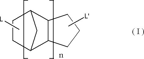
〔3〕
上記ロジン化合物が、ロジン、水添ロジン、酸変性ロジン及びエステル化ロジンから選ばれる1種以上のロジン化合物である、〔1〕又は〔2〕に記載の光学フィルム。
〔4〕
上記ロジン化合物が酸変性ロジンである、〔1〕~〔3〕のいずれかに記載の光学フィルム。
〔5〕
上記光学フィルムの透湿度が5.0~100g/m2/dayである、〔1〕~〔4〕のいずれかに記載の光学フィルム。
(ここで、光学フィルムの透湿度は、JIS Z-0208の手法で、40℃、相対湿度90%で24時間経過後の値である。)
〔6〕
(A)及び(B)を含有する層の透湿度が5.0~100g/m2/dayである、〔1〕~〔5〕のいずれかに記載の光学フィルム。
(ここで、透湿度は、JIS Z-0208の手法で、40℃、相対湿度90%で24時間経過後の値である。上記(A)及び(B)を含有する層の透湿度以下の式(1)によって算出される。
1/Jf=1/Js+1/Jb ・・・・・ 式(1)
上記式(1)中、Jbは光学フィルムを基材フィルムと、上記(A)及び(B)を含有する層とに分離したときの上記層の透湿度を表し、光学フィルムの透湿度をJf、基材フィルムの透湿度をJsとする。)
〔7〕
上記(A)及び(B)を含有する層の膜厚10μmであるときの上記(A)及び(B)を含有する層の換算透湿度が、5.0~100g/m2/dayである、〔1〕~〔6〕のいずれかに記載の光学フィルム。
(ここで、透湿度は、JIS Z-0208の手法で、40℃、相対湿度90%で24時間経過後の値である。膜厚10μmの上記(A)及び(B)を含有する層の透湿度以下の式(2)によって算出される。
Jb×db/10 ・・・・・ 式(2)
上記式(2)中、Jbは光学フィルムを基材フィルムと、上記(A)及び(B)を含有する層とに分離したときの上記層の透湿度を表し、db[μm]は低透湿層の膜厚を表す。)
〔8〕
上記基材フィルムがセルロースアシレートフィルムである〔1〕~〔7〕のいずれかに記載の光学フィルム。
〔9〕
上記基材フィルムが主鎖にラクトン環構造、無水グルタル酸環構造、及びグルタルイミド環構造のいずれか少なくとも1種を有する(メタ)アクリル系重合体である、〔1〕~〔7〕のいずれかに記載の光学フィルム。
〔10〕
上記光学フィルムが上記(A)及び(B)を含有する層上にハードコート層を更に有する、〔1〕~〔9〕のいずれかに記載の光学フィルム。
〔11〕
基材フィルム上に下記(A)及び(B)を含有する硬化性組成物を硬化して層を形成する工程を有する光学フィルムの製造方法。
(A)環状脂肪族炭化水素基とエチレン性不飽和二重結合とを有する化合物及びフルオレン環とエチレン性不飽和二重結合とを有する化合物の少なくともいずれかを上記硬化性組成物の全固形分を100質量%としたときに、全固形分に対し50~99質量%
(B)ロジン化合物を上記硬化性組成物の全固形分に対し1~50質量%
〔12〕
偏光子と、
該偏光子の保護フィルムとして〔1〕~〔10〕のいずれかに記載の光学フィルムとを少なくとも1枚含む偏光板。
〔13〕
液晶セルと、
該液晶セルの少なくとも一方に配置された〔12〕に記載の偏光板とを含み、
上記光学フィルムが最表層となるように配置された液晶表示装置。
以下に記載する構成要件の説明は、本発明の代表的な実施態様に基づいてなされることがあるが、本発明はそのような実施態様に限定されるものではない。なお、本明細書において「~」を用いて表される数値範囲は、「~」の前後に記載される数値を下限値及び上限値として含む範囲を意味する。
「アクリル樹脂」とはメタクリル酸又はアクリル酸の誘導体を重合して得られる樹脂、及びその誘導体を含有する樹脂を意味するものとする。また、特に限定しない場合には、「(メタ)アクリレート」はアクリレート及びメタクリレートを表し、「(メタ)アクリル」はアクリル及びメタクリルを表す。
更に、フィルムの「遅相軸方向」とはフィルム面内で屈折率が最大となる方向で、「進相軸方向」とはフィルム面内で遅相軸と直交する方向を意味するものとする。
本発明の光学フィルムは、基材フィルム上に、硬化性組成物の全固形分を100質量%としたときに、全固形分に対して下記(A)を50~99質量%及び(B)を1~50質量%含有する硬化性組成物を硬化して形成される層(以下、単に「低透湿層」ともいう。)を有する。
ここで、硬化性組成物の全固形分とは、硬化性組成物から溶剤を除いた全成分のことをいう。
(A)環状脂肪族炭化水素基とエチレン性不飽和二重結合とを有する化合物及びフルオレン環とエチレン性不飽和二重結合とを有する化合物の少なくともいずれか
(B)ロジン化合物
本発明において、低透湿層とは、硬化性組成物の全固形分を100質量%としたときに、固形分に対して(A)を50~99質量%及び(B)を1~50質量%含有する硬化性組成物を硬化して形成される層をいう。
低透湿層の透湿度は、膜厚10μmあたりの透湿度として5.0~250g/m2/dayであることが好ましく、5.0~100g/m2/dayであることが更に好ましく、5.0~100g/m2/dayであることが特に好ましい。
本発明は、上記光学フィルムの製造方法に関するものでもある。
本発明の光学フィルムの製造方法は、基材フィルム上に上記(A)を硬化性組成物の全固形分を100質量%としたときに、全固形分に対し50~99質量%及び上記(B)を硬化性組成物の全固形分に対し1~50質量%含有する硬化性組成物を硬化して低透湿層を形成する工程を有する。
本発明の光学フィルムは、上記(A)と(B)とを上記含有量で低透湿層に含有することにより、上記(A)と(B)の相乗効果により顕著に透湿度低減を達成することができ、耐久性に優れ、透湿度を低減することが出来る。
本発明の光学フィルムは、透湿度が5.0~100g/m2/dayであることが好ましい。(ここで、透湿度は、JIS Z-0208の手法で、40℃、相対湿度90%で24時間経過後の値である。)
本発明の光学フィルムの透湿度は、90g/m2/day以下であることが好ましく、80g/m2/day以下であることがより好ましく、70g/m2/day以下であることが更に好ましく、60g/m2/day以下であることが特に好ましい。透湿度が100g/m2/day以下であれば、液晶表示装置の常温、高湿及び高温高湿環境経時後の液晶セルの反りに伴う光漏れを抑制できる。
本発明の光学フィルムにおける低透湿層は、(A)環状脂肪族炭化水素基とエチレン性不飽和二重結合とを有する化合物及びフルオレン環とエチレン性不飽和二重結合とを有する化合物の少なくともいずれかを50~99質量%含有し、かつ
(B)ロジン化合物を1~50質量%含有する。必要に応じて更に、重合開始剤、透光性粒子、含フッ素又はシリコーン系化合物、溶剤を含有した硬化性組成物を、基材フィルム上に直接又は他の層を介して塗布・乾燥・硬化することにより形成することができる。
以下各成分について説明する。
環状脂肪族炭化水素基とエチレン性不飽和二重結合とを有する化合物は、バインダーとして機能し得る。
環状脂肪族炭化水素基とエチレン性不飽和二重結合とを有する化合物を用いることによって、低透湿性を実現でき、基材フィルムや他の層と、低透湿層との密着性に優れ、更に偏光板の光漏れを防止できる。詳細は明らかではないが、分子内に環状脂肪族炭化水素基を有する化合物を用いることで、低透湿層に疎水的な環状脂肪族炭化水素基を導入し、疎水化することで、外部から分子の取り込みを防止し、透湿度を低下させ得る。また、分子内にエチレン性不飽和二重結合を有することで、架橋点密度を上げ、低透湿層中の水分子の拡散経路を制限する。架橋点密度を上げることは、環状脂肪族炭化水素基の密度を相対的に上昇させる効果も有り、低透湿層内をより疎水的にし、水分子の吸着を防止し、透湿度を低下させると考えられる。
架橋点密度を上げるために分子内に有するエチレン性不飽和二重結合の数は2以上であることがより好ましい。
環状脂肪族炭化水素基としては、特に好ましくは、二環式、三環式等の、多環式化合物から誘導される基である。
より好ましくは、特開2006-215096号公報の特許請求の範囲記載の化合物の中心骨格、特開2001-10999号公報記載の化合物の中心骨格、あるいは、アダマンタン誘導体の骨格等が挙げられる。



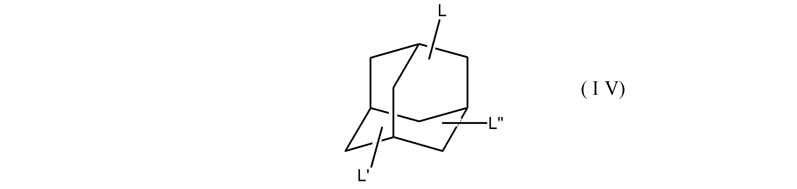

L、L’及びL’’についての2価以上の連結基としては、炭素数1~6の置換されていてもよいアルキレン基、N位が置換されていてもよいアミド結合、N位が置換されていてもよいウレタン結合、エステル結合、オキシカルボニル基、エーテル結合等、及びこれらの2以上を組み合わせて得られる基が挙げられる。
好ましくは、(メタ)アクリル酸、(メタ)アクリロイルクロリド、(メタ)アクリル酸無水物、(メタ)アクリル酸グリシジルなどの化合物や、WO2012/00316A号記載の化合物(例、1、1―ビス(アクリロキシメチル)エチルイソシアナート)を用いて、上記環状脂肪族炭化水素基を有するポリオールとの反応させることにより合成することができる。
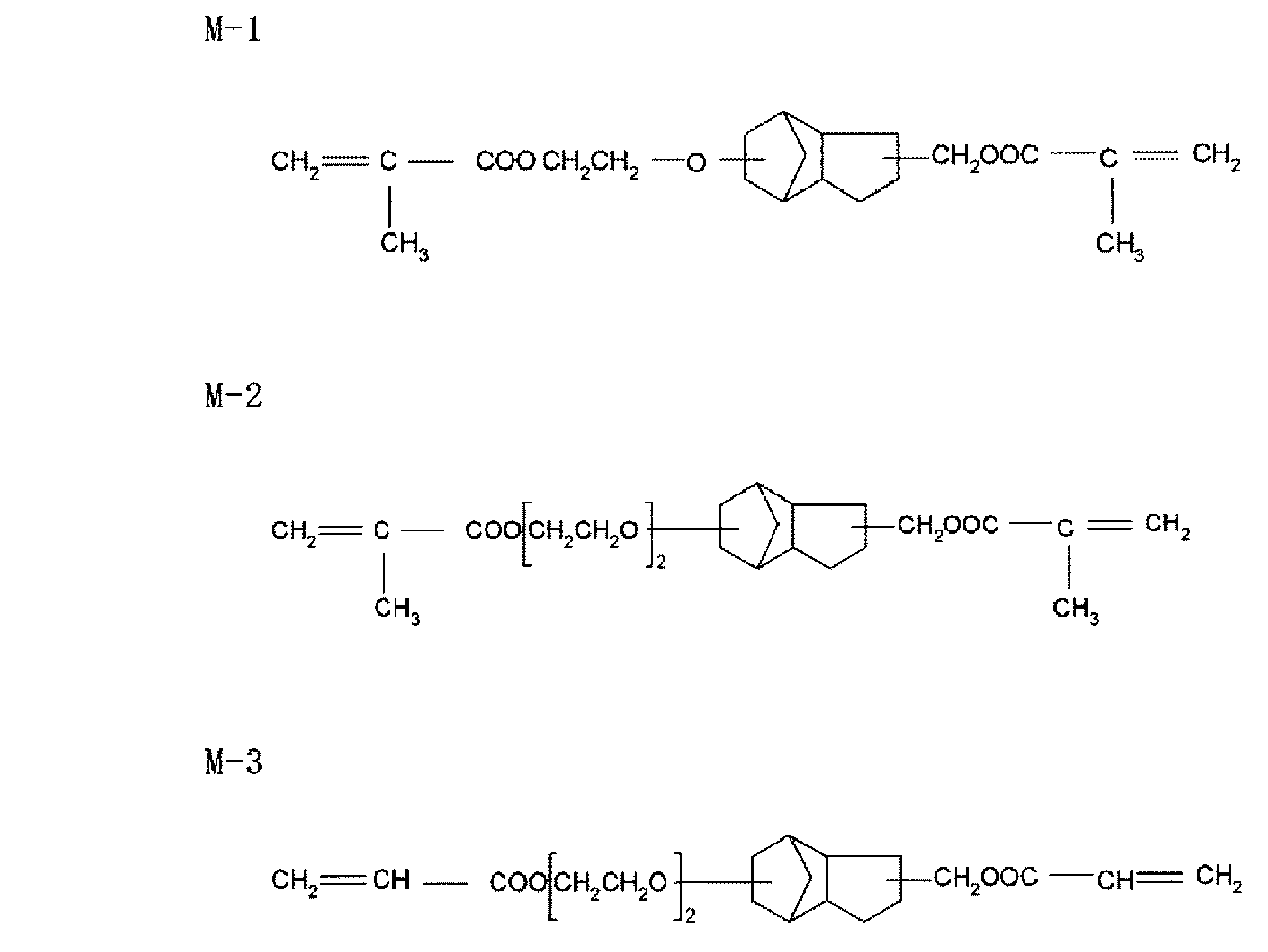

低透湿層に含有し得る、フルオレン環とエチレン性不飽和二重結合とを有する化合物はバインダーとして機能し得る。また、フルオレン環とエチレン性不飽和二重結合とを有する化合物は、硬化剤として機能することができ、塗膜の強度や耐擦傷性を向上させることが可能となると同時に低透湿性を付与することができる。
架橋点密度を上げるために分子内に有するエチレン性不飽和二重結合の数は2以上であることがより好ましい。

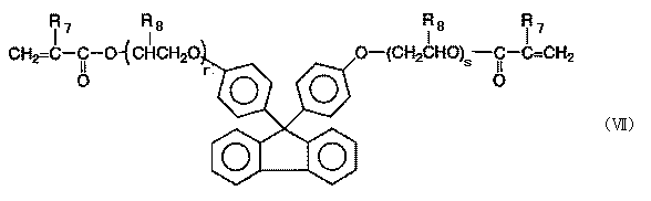
(A)環状脂肪族炭化水素基とエチレン性不飽和二重結合とを有する化合物及びフルオレン環とエチレン性不飽和二重結合とを有する化合物の少なくともいずれかの含有量は、上記低透湿層形成用の硬化性組成物の全固形分を100質量%としたときに、全固形分に対し50~99質量%であり、上記(A)と(B)との相乗効果による透湿度低減の顕著性の観点から、50質量%より多く99質量%以下であることが好ましく、55~95質量%であることがより好ましく、60~90質量%であることが更に好ましい。
本発明に用いる低透湿層形成用組成物中、分子内に環状脂肪族炭化水素基及びフルオレン環を有さないエチレン性不飽和二重結合を有する化合物を本発明の効果を損なわない範囲において併用できる。
環状脂肪族炭化水素基及びフルオレン環を有さないエチレン性不飽和二重結合を有する化合物を含有する場合の含有量は、上記低透湿層形成用の硬化性組成物の全固形分を100質量%としたときに、全固形分に対し1~30質量%であることが好ましく、2~20質量%がより好ましく、3~15質量%が更に好ましい。
低透湿層形成用硬化性組成物におけるロジン化合物(B)としては、ロジン、水添ロジン(水素化ロジンとも称する)、酸変性ロジン及びエステル化ロジン(ロジンエステルとも称する)から選ばれる1種類以上であることが好ましい。
ロジンとしては、アビエチン酸、レボピマール酸、パルストリン酸、ネオアビエチン酸、デヒドロアビエチン酸、或いはジヒドロアビエチン酸など樹脂酸を主成分とするトール油ロジン、ガムロジン、ウッドロジンなどの未変性ロジンが挙げられる。
水添ロジンとは、上記ロジンを水素化したものをいう。テトラヒドロアビエチン酸等のテトラヒドロ体を高含量(例えば50質量%以上)含むもの等が挙げられる。酸変性ロジンとしては、ディールズ・アルダー付加反応によりマレイン酸、フマル酸やアクリル酸などの不飽和酸を付加した不飽和酸変性ロジンが挙げられ、より具体的にはロジンにマレイン酸を付加したマレオピマール酸、フマル酸を付加したフマロピマール酸、アクリル酸を付加したアクリロピマール酸等が挙げられる。エステル化ロジンとしては、ロジンのアルキルエステル、ロジンとグリセリンとをエステル化反応させて得られるグリセリンエステル、ロジンとペンタエリスリトールとをエステル化して得られるペンタエリスリトールエステル等が挙げられる。
また、ロジンエステルとして、エステルガムAAG、エステルガムAAL、エステルガムA、エステルガムAAV、エステルガム105、エステルガムHS、エステルガムAT、エステルガムH、エステルガムHP、エステルガムHD、ペンセルA、ペンセルAD、ペンセルAZ、ペンセルC、ペンセルD-125、ペンセルD-135、ペンセルD-160、ペンセルKK(以上全て商品名、ロジンエステル系樹脂、荒川化学工業(株)製)、が挙げられる。
酸価が上記範囲のロジン化合物としては、前出の酸変性ロジンが挙げられ、特にマレイン酸やフマル酸をディールズ・アルダー反応で付加したロジン化合物が本発明では好ましく用いられる。
また、本発明においてロジン化合物は酸変性した後に水添処理をしたものを用いるのが好ましい。水添処理を施すことでロジン化合物の残存二重結合が低透湿層内で酸化されフィルムが着色することを防止することが出来る。
ロジン化合物の軟化点は、70~170℃が好ましい。ロジン化合物の軟化点が70℃以上のであると、硬化層が柔らかくならずブロッキング性に優れる。軟化点が170℃未満であると溶剤に対する溶解性を保つことができ、硬化層のヘイズが上昇しづらい利点がある。
本発明においてロジン化合物の軟化点は、JIS K-2531の環球法により測定することができる。
(B)ロジン化合物の含有量は、上記低透湿層形成用の硬化性組成物の全固形分を100質量%としたときに、全固形分に対し1~50質量%であり、上記(A)と(B)との相乗効果による透湿度低減の顕著性の観点から、10~40質量%であることが好ましく、20~30質量%であることがより好ましい。
本発明の低透湿層の透湿度を更に低減するためには、上述の低透湿層に用いることが可能なバインダー中に無機層状化合物を分散することも好ましい。無機層状化合物は親水性の表面を有するため、有機化処理することが好ましい。
また、かかる無機層状化合物は、これら無機層状化合物に有機化処理を施したものであることが好ましい。
上記有機化処理された無機層状化合物としては、特開2012-234094号公報段落0038~0044に記載の有機化処理された無機層状化合物が挙げられる。
分子内に環状脂肪族炭化水素基とエチレン性不飽和二重結合を有する化合物及び/又は分子内にフルオレン骨格とエチレン性不飽和二重結合を有する化合物を含有する組成物には、重合開始剤を含むことが好ましい。重合開始剤としては光重合開始剤が好ましい。
光重合開始剤としては、アセトフェノン類、ベンゾイン類、ベンゾフェノン類、ホスフィンオキシド類、ケタール類、アントラキノン類、チオキサントン類、アゾ化合物、過酸化物類、2,3-ジアルキルジオン化合物類、ジスルフィド化合物類、フルオロアミン化合物類、芳香族スルホニウム類、ロフィンダイマー類、オニウム塩類、ボレート塩類、活性エステル類、活性ハロゲン類、無機錯体、クマリン類などが挙げられる。光重合開始剤の具体例、及び好ましい態様、市販品などは、特開2009-098658号公報の段落[0133]~[0151]に記載されており、本発明においても同様に好適に用いることができる。
低透湿層を含む本発明の光学フィルムは、偏光板又は液晶表示装置部材に使用されるが、偏光板又は液晶等の劣化防止の観点から、低透湿層に紫外線吸収剤を含有することで、光学フィルムに紫外線吸収性を付与することもできる。
紫外線吸収剤としては、公知のものを用いることができる。例えば、特開2001-72782号公報や特表2002-543265号公報に記載の紫外線吸収剤が挙げられる。紫外線吸収剤の具体例、及び好ましい例としては、{基材フィルム}<紫外線吸収剤>の項において後述する紫外線吸収剤の具体例、及び好ましい例と同様のものが挙げられる。
低透湿層形成用の硬化性組成物は、溶剤を含有することができる。溶剤としては、モノマーの溶解性、塗工時の乾燥性、透光性粒子の分散性等を考慮し、各種溶剤を用いることができる。係る有機溶剤としては、例えばジブチルエーテル、ジメトキシエタン、ジエトキシエタン、プロピレンオキシド、1,4-ジオキサン、1,3-ジオキソラン、1,3,5-トリオキサン、テトラヒドロフラン、アニソール、フェネトール、炭酸ジメチル、炭酸メチルエチル、炭酸ジエチル、アセトン、メチルエチルケトン(MEK)、ジエチルケトン、ジプロピルケトン、ジイソブチルケトン、シクロペンタノン、シクロヘキサノン、メチルシクロヘキサノン、蟻酸エチル、蟻酸プロピル、蟻酸ペンチル、酢酸メチル、酢酸エチル、酢酸プロピル、プロピオン酸メチル、プロピオン酸エチル、γ-プチロラクトン、2-メトキシ酢酸メチル、2-エトキシ酢酸メチル、2-エトキシ酢酸エチル、2-エトキシプロピオン酸エチル、2-メトキシエタノール、2-プロポキシエタノール、2-ブトキシエタノール、1,2-ジアセトキシアセトン、アセチルアセトン、ジアセトンアルコール、アセト酢酸メチル、アセト酢酸エチル等メチルアルコール、エチルアルコール、イソプロピルアルコール、n-ブチルアルコール、シクロヘキシルアルコール、酢酸イソブチル、メチルイソブチルケトン(MIBK)、2-オクタノン、2-ペンタノン、2-ヘキサノン、エチレングリコールエチルエーテル、エチレングリコールイソプロピルエーテル、エチレングリコールブチルエーテル、プロピレングリコールメチルエーテル、エチルカルビトール、ブチルカルビトール、ヘキサン、ヘプタン、オクタン、シクロヘキサン、メチルシクロヘキサン、エチルシクロヘキサン、ベンゼン、トルエン、キシレン等が挙げられ、1種単独であるいは2種以上を組み合わせて用いることができる。
本発明の低透湿層は、1層であってもよいし、複数層設けてもよい。上記低透湿層の積層方法は特に限定されないが、上記低透湿層を基材フィルムとの共流延として作製すること、又は、上記低透湿層を上記基材フィルム上に塗布にて設けることが好ましく、上記低透湿層を上記基材フィルム上に塗布にて設けることがより好ましい。
本発明の低透湿層の膜厚は、0.5~25μmであることが好ましく、1~20μmであることがより好ましく、2~18μmであることが更に好ましく、3~17μmであることが特に好ましい。
複合フィルムの気体透過式より(例えば、「包装材料のバリア性の科学(包装学基礎講座5)」p68~72 仲川勤著 日本包装学会)、定常状態の光学フィルムの透湿度をJf、基材フィルムの透湿度をJs、光学フィルムを基材フィルムと低透湿層に分離したときの低透湿層の透湿度をJbとしたときに、以下の式が成り立つ。
1/Jf=1/Js+1/Jb ・・・・・式(1)
光学フィルムの透湿度Jfと基材フィルムの透湿度Jsは直接測定することができ、それらの測定値を基に、低透湿層の透湿度Jbを計算で求めることができる。
本発明において、低透湿層の透湿度が5.0~100g/m2/dayであることが好ましい。
一般に定常状態に於ける透湿度は膜厚に反比例することが知られている。従って、上記膜厚の範囲で低透湿層が到達できる透湿度は材料の特性値である単位膜厚当たりの透湿度で決まり、その値が小さいほどより低透湿度に到達することができる。一方、上記の関係を基に低透湿層の膜厚調整で透湿度の調整をすることができるが、単位膜厚当たりの透湿度が低過ぎると光学フィルムの透湿度の制御が難しくなる。
両者を考慮して、低透湿層の膜厚10μmあたりの透湿度は5.0~100g/m2/dayが好ましく、10~100g/m2/dayがより好ましく、20~90g/m2/dayがより好ましく、30~80g/m2/dayが特に好ましい。
(透湿度は、JIS Z-0208の手法で、40℃、相対湿度90%で24時間経過後の値である。)
なお、低透湿層の膜厚10μmにあたりの透湿度は基材フィルムと光学フィルムの透湿度、低透湿層の膜厚から以下のように見積もられる。
Cb(10μm)=Jb×db/10 [g/m2/day]・・・・・式(2)
(ここで、db[μm]は低透湿層の膜厚であり、上記の通り、低透湿層積層前後の膜厚差から求めることができる。)
[基材フィルムの材質]
基材フィルムを形成する材料としては、光学性能透明性、機械的強度、熱安定性、等方性などに優れるポリマーが好ましい。本発明でいう透明とは、可視光の透過率が60%以上であることを示し、好ましくは80%以上であり、特に好ましくは90%以上である。例えば、ポリカーボネート系ポリマー、ポリエチレンテレフタレートやポリエチレンナフタレート等のポリエステル系ポリマー、ポリメチルメタクリレート等の(メタ)アクリル系ポリマー、ポリスチレンやアクリロニトリル・スチレン共重合体(AS樹脂)等のスチレン系ポリマーなどがあげられる。また、ポリエチレン、ポリプロピレン等のポリオレフィン、エチレン・プロピレン共重合体の如きポリオレフィン系ポリマー、塩化ビニル系ポリマー、ナイロンや芳香族ポリアミド等のアミド系ポリマー、イミド系ポリマー、スルホン系ポリマー、ポリエーテルスルホン系ポリマー、ポリエーテルエーテルケトン系ポリマー、ポリフェニレンスルフィド系ポリマー、塩化ビニリデン系ポリマー、ビニルブチラール系ポリマー、アリレート系ポリマー、ポリオキシメチレン系ポリマー、エポキシ系ポリマー、又は上記ポリマーを混合したポリマーも例としてあげられる。また本発明の高分子フィルムは、アクリル系、ウレタン系、アクリルウレタン系、エポキシ系、シリコーン系等の紫外線硬化型、熱硬化型の樹脂の硬化層として形成することもできる。
次に上述のセルロースを原料に製造される本発明のセルロースアシレートについて記載する。セルロースアシレートはセルロースの水酸基がアシル化されたもので、その置換基はアシル基の炭素原子数が2のアセチル基から炭素原子数が22のものまでいずれも用いることができる。本発明のセルロースアシレートにおいて、セルロースの水酸基へのアシル基の置換度は特に限定されないが、セルロースの水酸基をアシル化する酢酸及び/又は炭素原子数3~22のカルボン酸の結合度を測定し、計算によって置換度を得ることができる。測定方法としては、ASTMのD-817-91に準じて実施することが出来る。
[セルロースアシレートの重合度]
本発明で好ましく用いられるセルロースアシレートの重合度は、粘度平均重合度で180~700であり、セルロースアセテートにおいては、180~550がより好ましく、180~400が更に好ましく、180~350が特に好ましい。
上記(メタ)アクリル系重合体は、繰り返し構造単位として(メタ)アクリル酸エステル単量体由来の繰り返し構造単位を有することが好ましい。
CH2=C(X)R201
上記(メタ)アクリル酸エステルを用いる場合、重合工程に供する単量体成分中のその含有割合は、本発明の効果を十分に発揮させる上で、好ましくは10~100質量%、より好ましくは10~100質量%、更に好ましくは40~100質量%、特に好ましくは50~100質量%である。
上記水酸基含有単量体を用いる場合、重合工程に供する単量体成分中のその含有割合は、本発明の効果を十分に発揮させる上で、好ましくは0~30質量%、より好ましくは0~20質量%、更に好ましくは0~15質量%、特に好ましくは0~10質量%である。
上記不飽和カルボン酸を用いる場合、重合工程に供する単量体成分中のその含有割合は、本発明の効果を十分に発揮させる上で、好ましくは0~30質量%、より好ましくは0~20質量%、更に好ましくは0~15質量%、特に好ましくは0~10質量%である。
上記一般式(201)で表される単量体を用いる場合、重合工程に供する単量体成分中のその含有割合は、本発明の効果を十分に発揮させる上で、好ましくは0~30質量%、より好ましくは0~20質量%、更に好ましくは0~15質量%、特に好ましくは0~10質量%である。
(メタ)アクリル系重合体の中でも主鎖に環構造を有するものが好ましい。主鎖に環構造を導入することで、主鎖の剛直性を高め、耐熱性を向上することができる。
本発明では主鎖に環構造を有する(メタ)アクリル系重合体の中でも主鎖にラクトン環構造を含有する重合体、主鎖に無水グルタル酸環構造を有する重合体、主鎖にグルタルイミド環構造を有する重合体のいずれかであることが好ましい。中でも主鎖にラクトン環構造を形成する重合体であることがより好ましい。
以下のこれらの主鎖に環構造を有する重合体について順に説明する。
主鎖にラクトン環構造を有する(メタ)アクリル系重合体(以降ラクトン環含有重合体とも称す)は、主鎖にラクトン環を有する(メタ)アクリル系重合体であれば特に限定されないが、好ましくは下記一般式(401)で示されるラクトン環構造を有する。
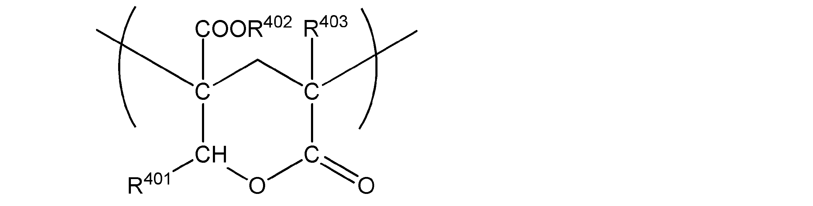
また、本発明の製造方法の第一の態様では、(メタ)アクリル系樹脂を溶剤に溶解させて溶液流延を行って形成するため、(メタ)アクリル系樹脂の合成時における溶剤は、溶融製膜を行う場合よりも限定されず、沸点が高い溶剤を用いて合成してもよい。
重合開始剤の量の調整により、重合体の重量平均分子量を調整することができる。
主鎖に無水グルタル酸環構造を有する重合体とは、グルタル酸無水物単位を有する重合体である。

一般式(102):-[CH2-C(R41)COOR42]-
一般式(103):CH2=C(R41)COOR42
一般式(104):-[CH2―C(R51)COOH]-
ここでR51は水素又は炭素数1~5のアルキル基を表す。
一般式(105):CH2=C(R51)COOH
主鎖にグルタルイミド環構造を有する(メタ)アクリル系重合体(以降グルタルイミド系樹脂とも称す)は、主鎖にグルタルイミド環構造を有することによって光学特性や耐熱性などの点で好ましい特性バランスを発現できる。上記主鎖にグルタルイミド環構造を有する(メタ)アクリル系重合体は、少なくとも下記一般式(301):
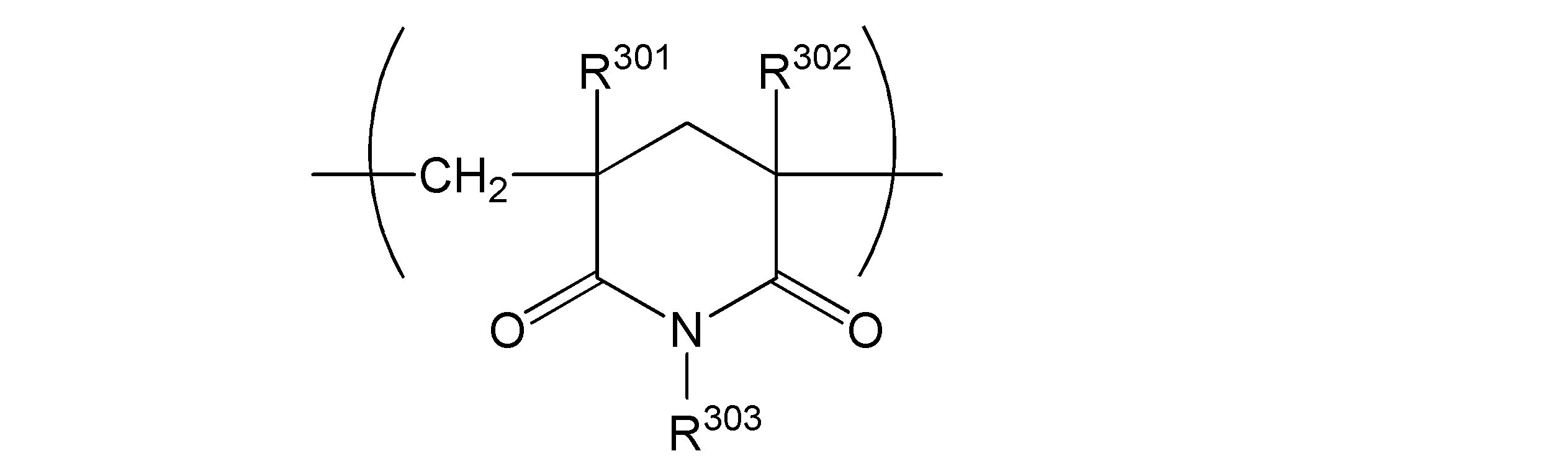
上記基材フィルムに好ましく使用される紫外線吸収剤について説明する。上記基材フィルムを含む本発明の光学フィルムは、偏光板又は液晶表示用部材等に使用されるが、偏光板又は液晶等の劣化防止の観点から、紫外線吸収剤が好ましく用いられる。紫外線吸収剤としては、波長370nm以下の紫外線の吸収能に優れ、かつ良好な液晶表示性の観点から、波長400nm以上の可視光の吸収が少ないものが好ましく用いられる。紫外線吸収剤は1種のみ用いても良いし、2種以上を併用しても良い。例えば、特開2001-72782号公報や特表2002-543265号公報に記載の紫外線吸収剤が挙げられる。紫外線吸収剤の具体例としては、例えばオキシベンゾフェノン系化合物、ベンゾトリアゾール系化合物、サリチル酸エステル系化合物、ベンゾフェノン系化合物、シアノアクリレート系化合物、ニッケル錯塩系化合物などが挙げられる。
上記基材フィルムには、マット剤、レターデーション発現剤、可塑剤、紫外線吸収剤、劣化防止剤、剥離剤、赤外線吸収剤、波長分散調整剤などの添加剤を加えることができ、それらは固体でもよく油状物でもよい。すなわち、その融点や沸点において特に限定されるものではない。例えば20℃以下と20℃以上の紫外線吸収材料の混合や、同様に可塑剤の混合などであり、例えば特開2001-151901号などに記載されている。更にまた、赤外吸収染料としては例えば特開2001-194522号に記載されている。またその添加する時期はドープ作製工程において何れで添加しても良いが、ドープ調製工程の最後の調製工程に添加剤を添加し調製する工程を加えて行ってもよい。更にまた、各素材の添加量は機能が発現する限りにおいて特に限定されない。また、光学フィルムが多層から形成される場合、各層の添加物の種類や添加量が異なってもよい。例えば特開2001-151902号などに記載されているが、これらは従来から知られている技術である。これらの詳細は、発明協会公開技報(公技番号2001-1745、2001年3月15日発行、発明協会)にて16頁~22頁に詳細に記載されている素材が好ましく用いられる。
これらの添加剤により、フィルムの脆性が改良され、フィルムの耐折試験(180度折り曲げ時の割れ評価など)が大幅に改善する。
また、低ヘイズを達成するためには、上記添加物の屈折率は基材フィルムと略同一の屈折率を持つ事が好ましく、屈折率差は0.5以下が好ましく、0.3以下がより好ましい。
(基材フィルムの厚さ)
上記基材フィルムの膜厚は、5~100μmが好ましく、10~80μmがより好ましく、15~70μmが特に好ましく、20~60μmがより特に好ましい。膜厚を上記の範囲に制御することで低透湿層を積層した後に液晶表示装置の置かれる環境、すなわち温湿度変化に伴うパネルのムラ小さくすることができる。
上記基材フィルムの透湿度は、JIS Z-0208をもとに、40℃、相対湿度90%の条件において測定される。
上記基材フィルムの透湿度は、300g/m2/day以下であることが好ましく、250g/m2/day以下であることがより好ましく、200g/m2/day以下であることが更に好ましく、150g/m2/day以下であることが特に好ましい。基材フィルムの透湿度を上記範囲に制御することで、低透湿層を積層した光学フィルム(本発明の光学フィルム)を搭載した液晶表示装置の常温、高湿及び高温高湿環境経時後の、液晶セルの反りや、光漏れを抑制できる。
低透湿層の(単位膜厚当たりの透湿度)で説明したように、基材フィルム10μmの透湿度は以下の式で与えられる。
Cs(10μm)=Js×ds/10 [g/m2/day]
(ここで、ds[μm]は基材フィルムの膜厚であり、Jsは基材フィルムの透湿度である。)
基材フィルムの膜厚が10μmに対する透湿度は50~2000g/m2/dayが好ましく、80~1500g/m2/dayがより好ましく、100~1000g/m2/dayがより好ましく、150~800g/m2/dayが特に好ましい。
(透湿度は、JIS Z-0208の手法で、40℃、相対湿度90%で24時間経過後の値である。)
また、基材フィルムと低透湿層の膜厚が10μmの透湿度Cb(10μm)/Cs(10μm)は、1.5~30であることが好ましく、2~20であることがより好ましく、3~10であることが特に好ましい。
下限値以上で充分な低透湿効果が得られ、上限値以下でカールを抑止できる。
透湿度を低減するためには、フィルム中の水の拡散を抑える事が好ましく、すなわちフィルムの自由体積を下げる事が好ましい。一般的にフィルムの自由体積はフィルムの酸素透過係数と相関する。
上記基材フィルムの酸素透過係数は、100cc・mm/(m2・day・atm)以下が好ましく、30cc・mm/(m2・day・atm)以下がより好ましい。
上記基材フィルムの含水率(平衡含水率)は、偏光板の保護フィルムとして用いる際、ポリビニルアルコールなどの水溶性熱可塑性との接着性を損なわないために、膜厚のいかんに関わらず、25℃、相対湿度80%における含水率が、0~4質量%であることが好ましい。0~2.5質量%であることがより好ましく、0~1.5質量%であることが更に好ましい。平衡含水率が4質量%以下であれば、レターデーションの湿度変化による依存性が大きくなり過ぎず、液晶表示装置の常温、高湿及び高温高湿環境経時後の光漏れを抑止の点からも好ましい。
含水率の測定は、フィルム試料7mm×35mmを水分測定器、試料乾燥装置“CA-03”及び“VA-05”{共に三菱化学(株)製}にて、カールフィッシャー法により水分量(g)を求めた後、水分量(g)を試料質量(g)で除して行うことができる。
上記基材フィルムの寸度安定性は、60℃、相対湿度90%の条件下に24時間静置した場合(高湿)の寸度変化率、及び80℃、DRY環境(相対湿度5%以下)の条件下に24時間静置した場合(高温)の寸度変化率が、いずれも0.5%以下であることが好ましい。より好ましくは0.3%以下であり、更に好ましくは0.15%以下である。
上記基材フィルムの製造方法は、熱可塑性樹脂及び溶剤を含む高分子溶液を支持体上に流延して高分子膜(上記基材フィルム)を形成する工程、あるいは、熱可塑性樹脂を溶融製膜して基材フィルムを形成する工程を含むことが好ましい。すなわち、上記基材フィルムは、上記熱可塑性樹脂及び溶剤を含む高分子溶液を支持体上に流延して製膜されてなること、あるいは、熱可塑性樹脂を溶融製膜されてなることが好ましく、熱可塑性樹脂を溶融製膜されてなることがより好ましい。
基材フィルムは、場合により表面処理を行うことによって、基材フィルムと低透湿層やそれ以外の層(例えば、偏光子、下塗層及びバック層)との接着の向上を達成することができる。例えばグロー放電処理、紫外線照射処理、コロナ処理、火炎処理、酸又はアルカリ処理を用いることができる。ここでいうグロー放電処理とは、10-3~20Torrの低圧ガス下でおこる低温プラズマでもよく、更にまた大気圧下でのプラズマ処理も好ましい。プラズマ励起性気体とは上記のような条件においてプラズマ励起される気体をいい、アルゴン、ヘリウム、ネオン、クリプトン、キセノン、窒素、二酸化炭素、テトラフルオロメタンの様なフロン類及びそれらの混合物などがあげられる。これらについては、詳細が発明協会公開技報(公技番号 2001-1745、2001年3月15日発行、発明協会)にて30頁~32頁に詳細に記載されており、本発明において好ましく用いることができる。
また本発明の光学フィルムは上記低透湿層を有するが、更に、少なくとも一方の表面に、機能層を積層してもよい。この機能層の種類は特に限定されないが、ハードコート層、反射防止層(低屈折率層、中屈折率層、高屈折率層など屈折率を調整した層)、防眩層、帯電防止層、紫外線吸収層、密着層(基材と低透湿層や機能性層の密着性を向上させる層)などが挙げられる。
上記機能層は、1層であってもよいし、複数層設けてもよい。上記機能層の積層方法は特に限定されない。
機能層は基材フィルムの低透湿層を設けた面に積層しても良い。この場合、機能層が低透湿層と接していても接していなくても良い。また、低透湿層を積層していない面に積層しても良い。複数の機能層を積層する場合一つの機能層を低透湿層上に積層し、もう一つの機能層を低透湿層が積層していない面に積層することもできる。なかでも低透湿層を積層後の本発明の光学フィルム上に、更に他の機能層を塗設して設けることが好ましい。
(光学フィルムの膜厚)
本発明の光学フィルムの膜厚(基材フィルムに低透湿層を積層した後の総膜厚)は、5~100μmが好ましく、10~80μmがより好ましく、15~75μmが特に好ましい。
本発明の光学フィルムは、基材フィルムの一方の面上に低透湿層を有し、偏光板保護フィルムでありかつ、液晶表示装置の表面フィルムであることが好ましい。本発明の光学フィルムが表面フィルムの場合、ハードコート層が積層されていることが好ましい。この場合の好ましい層構成を以下に示す。
基材フィルム/密着層/低透湿層/ハードコート層
基材フィルム/ハードコート層/低透湿層
基材フィルム/密着層/ハードコート層/低透湿層
低透湿層/基材フィルム/ハードコート層
基材フィルム/低透湿層/ハードコート層/反射防止層
基材フィルム/ハードコート層/低透湿層/反射防止層
低透湿層/基材フィルム/ハードコート層/反射防止層
基材フィルム/低透湿層/ハードコート層/反射防止層/防汚層
本発明の光学フィルムには、機能層としてハードコート層を設けることも好ましい。
本発明において、ハードコート層とは、該層を形成することで透明支持体の鉛筆硬度が上昇する層をいう。実用的には、ハードコート層積層後の鉛筆硬度(JIS K-5400)はH以上が好ましく、更に好ましくは2H以上であり、最も好ましくは3H以上である。
ハードコート層の厚みは、0.4~35μmが好ましく、更に好ましくは1~30μmであり、最も好ましくは1.5~20μmである。
本発明においてハードコート層は1層でも複数でもかまわない。ハードコート層が複数層の場合、全てのハードコート層の膜厚の合計が上位範囲であることが好ましい。
本発明の光学フィルムのハードコート層の表面は平坦であって凹凸があっても構わない。また、必要に応じて、表面凹凸や内部散乱付与のためにハードコート層に透光性粒子を含有させることもできる。
本発明において、ハードコート層は、エチレン性不飽和二重結合を有する化合物、重合開始剤、必要に応じて、透光性粒子、含フッ素又はシリコーン系化合物、溶剤を含有する組成物を、支持体上に直接又は他の層を介して塗布・乾燥・硬化することにより形成することができる。以下各成分について説明する。
本発明のハードコート層形成用組成物にはエチレン性不飽和二重結合を有する化合物を含有することができる。エチレン性不飽和二重結合を有する化合物はバインダーとして機能することができ、重合性不飽和基を2つ以上有する多官能モノマーであることが好ましい。該重合性不飽和基を2つ以上有する多官能モノマーは、硬化剤として機能することができ、塗膜の強度や耐擦傷性を向上させることが可能となる。重合性不飽和基は3つ以上であることがより好ましい。これらモノマーは、1又は2官能のモノマーと3官能以上のモノマーを併用して用いることもできる。
ハードコート層形成用組成物が分子内に環状脂肪族炭化水素とエチレン性不飽和二重結合を有する化合物を含有する場合、分子内に環状脂肪族炭化水素とエチレン性不飽和二重結合を有する化合物はハードコート層形成用組成物中のエチレン性不飽和二重結合を有する化合物中、1~90質量%が好ましく、2~80質量%がより好ましく、5~70質量%が特に好ましい。
ハードコート層形成用組成物が更に、5官能以上の(メタ)アクリレートを含有する場合、5官能以上の(メタ)アクリレートは、ハードコート層形成用組成物中のエチレン性不飽和二重結合を有する化合物中、1~70質量%が好ましく、2~60質量%がより好ましく、5~50質量%が特に好ましい。
本発明のハードコート層に透光性粒子を含有させることで、ハードコート層表面に凹凸形状を付与したり、内部ヘイズを付与することもできる。
また、透光性粒子と、ハードコート層のバインダーとの屈折率の差(「透光性粒子の屈折率」-「該透光性粒子を除くハードコート層の屈折率」)は、絶対値として、好ましくは0.05未満であり、より好ましくは0.001~0.030、更に好ましくは0.001~0.020である。ハードコート層中の透光性粒子とバインダーとの屈折率の差を0.05未満にすると、透光性粒子による光の屈折角度が小さくなり、散乱光が広角まで広がらず、光学異方性層の透過光の偏光を解消するなどの悪化作用が無く好ましい。
好ましい第1の態様としては、3官能以上の(メタ)アクリレートモノマーを主成分としたバインダー(硬化後の屈折率が1.50~1.53)とアクリル含率50~100質量パーセントである架橋ポリ(メタ)アクリレート/スチレン重合体からなる透光性粒子を組み合わせて用いることが好ましい。低屈折率であるアクリル成分と高屈折率であるスチレン成分の組成比を調節することで、透光性粒子とバインダーとの屈折率差を0.05未満にすることが容易である。アクリル成分とスチレン成分の比率は質量比で50/50~100/0が好ましく、更に好ましくは60/40~100/0であり、最も好ましくは65/35~90/10である。架橋ポリ(メタ)アクリレート/スチレン重合体からなる透光性粒子の屈折率としては、1.49~1.55が好ましく、更に好ましくは1.50~1.54であり、最も好ましくは1.51~1.53である。
好ましい第2の態様としては、3官能以上の(メタ)アクリレートモノマーを主成分としたバインダーに対して、1~100nmの平均粒子サイズの無機微粒子を併用することで、モノマーと無機微粒子からなるバインダーの屈折率を調節し、既存の透光性粒子との屈折率差を調節するものである。無機粒子としては、珪素、ジルコニウム、チタン、アルミニウム、インジウム、亜鉛、錫、アンチモンのうちより選ばれる少なくとも一つの金属の酸化物、具体例としては、SiO2、ZrO2、TiO2、Al2O3、In2O3、ZnO、SnO2、Sb2O3、ITO等が挙げられる。好ましくは、SiO2、ZrO2、Al2O3などが挙げられる。これら無機粒子は、モノマーの総量に対して1~90質量%の範囲で混合して用いることができ、好ましくは5~65質量%である。
ここで、該透光性粒子を除くハードコート層の屈折率は、アッベ屈折計で直接測定するか、分光反射スペクトルや分光エリプソメトリーを測定するなどして定量評価できる。上記透光性粒子の屈折率は、屈折率の異なる2種類の溶剤の混合比を変化させて屈折率を変化させた溶剤中に透光性粒子を等量分散して濁度を測定し、濁度が極小になった時の溶剤の屈折率をアッベ屈折計で測定することで測定される。
透光性粒子の製造法は、懸濁重合法、乳化重合法、ソープフリー乳化重合法、分散重合法、シード重合法等を挙げることができ、いずれの方法で製造されてもよい。これらの製造法は、例えば「高分子合成の実験法」(大津隆行、木下雅悦共著、化学同人社)130頁及び146頁から147頁の記載、「合成高分子」1巻、p.246~290、同3巻、p.1~108等に記載の方法、及び特許第2543503号明細書、同第3508304号明細書、同第2746275号明細書、同第3521560号明細書、同第3580320号明細書、特開平10-1561号公報、特開平7-2908号公報、特開平5-297506号公報、特開2002-145919号公報等に記載の方法を参考にすることができる。
分級には風力分級法、遠心分級法、沈降分級法、濾過分級法、静電分級法等の方法を用いることが好ましい。
ここでいう増粘剤とは、それを添加することにより液の粘度が増大するものを意味する。
ポリ-ε-カプロラクトン
ポリ-ε-カプロラクトンジオール
ポリ-ε-カプロラクトントリオール
ポリビニルアセテート
ポリ(エチレンアジペート)
ポリ(1,4-ブチレンアジペート)
ポリ(1,4-ブチレングルタレート)
ポリ(1,4-ブチレンスクシネート)
ポリ(1,4-ブチレンテレフタレート)
ポリ(エチレンテレフタレート)
ポリ(2-メチル-1,3-プロピレンアジペート)
ポリ(2-メチル-1,3-プロピレングルタレート)
ポリ(ネオペンチルグリコールアジペート)
ポリ(ネオペンチルグリコール セバケート)
ポリ(1,3-プロピレンアジペート)
ポリ(1,3-プロピレン グルタレート)
ポリビニルブチラール
ポリビニルホルマール
ポリビニルアセタール
ポリビニルプロパナール
ポリビニルヘキサナール
ポリビニルピロリドン
ポリアクリル酸エステル
ポリメタクリル酸エステル
セルロースアセテート
セルロースプロピオネート
セルロースアセテートブチレート
ハードコート層形成用組成物には光重合開始剤を含有させることが好ましい。低透湿層で説明した光重合開始剤をハードコート層形成用組成物でも好ましく用いることができる。
本発明の光学フィルムは、偏光板又は液晶表示装置部材に使用されるが、偏光板又は液晶等の劣化防止の観点から、UV硬化を阻害しない範囲でハードコート層に紫外線吸収剤を含有することで、光学フィルムに紫外線吸収性を付与することもできる。
本発明のハードコート層形成用組成物は、溶剤を含有することができる。溶剤としては、モノマーの溶解性、透光性粒子の分散性、塗工時の乾燥性等を考慮し、各種溶剤を用いることができる。係る有機溶剤としては、例えばジブチルエーテル、ジメトキシエタン、ジエトキシエタン、プロピレンオキシド、1,4-ジオキサン、1,3-ジオキソラン、1,3,5-トリオキサン、テトラヒドロフラン、アニソール、フェネトール、炭酸ジメチル、炭酸メチルエチル、炭酸ジエチル、アセトン、メチルエチルケトン(MEK)、ジエチルケトン、ジプロピルケトン、ジイソブチルケトン、シクロペンタノン、シクロヘキサノン、メチルシクロヘキサノン、蟻酸エチル、蟻酸プロピル、蟻酸ペンチル、酢酸メチル、酢酸エチル、酢酸プロピル、プロピオン酸メチル、プロピオン酸エチル、γ-プチロラクトン、2-メトキシ酢酸メチル、2-エトキシ酢酸メチル、2-エトキシ酢酸エチル、2-エトキシプロピオン酸エチル、2-メトキシエタノール、2-プロポキシエタノール、2-ブトキシエタノール、1,2-ジアセトキシアセトン、アセチルアセトン、ジアセトンアルコール、アセト酢酸メチル、アセト酢酸エチル等メチルアルコール、エチルアルコール、イソプロピルアルコール、n-ブチルアルコール、シクロヘキシルアルコール、酢酸イソブチル、メチルイソブチルケトン(MIBK)、2-オクタノン、2-ペンタノン、2-ヘキサノン、エチレングリコールエチルエーテル、エチレングリコールイソプロピルエーテル、エチレングリコールブチルエーテル、プロピレングリコールメチルエーテル、エチルカルビトール、ブチルカルビトール、ヘキサン、ヘプタン、オクタン、シクロヘキサン、メチルシクロヘキサン、エチルシクロヘキサン、ベンゼン、トルエン、キシレン等が挙げられ、1種単独であるいは2種以上を組み合わせて用いることができる。
上記のようにハードコート層上に反射防止層を積層することも本発明の好ましい態様の一つである。本発明では公知の反射防止層を好ましく用いることができる、中でもUV硬化型の反射防止層が好ましい。
反射防止層は1層構成の膜厚λ/4の低反射率層でも多層構成でも良いが、1層構成の膜厚λ/4の低反射率層が特に好ましい。本発明で好ましく使用することが出来る低屈折材料に関し、以下に説明するが本発明は以下に限定されるものではない。
以下に低屈折率層の材料について説明する。
低屈折率化、耐擦傷性改良の観点から、低屈折率層に無機微粒子を用いることが好ましい。該無機微粒子は、平均粒子サイズが5~120nmであれば特に制限はないが、低屈折率化の観点からは、無機の低屈折率粒子が好ましい。
低屈折率化を図るには、多孔質又は中空構造の微粒子を使用することが好ましい。特に中空構造のシリカ粒子を用いることが好ましい。これら粒子の空隙率は、好ましくは10~80%、更に好ましくは20~60%、最も好ましくは30~60%である。中空微粒子の空隙率を上述の範囲にすることが、低屈折率化と粒子の耐久性維持の観点で好ましい。
また、本発明においては無機微粒子は常法によりシランカップリング剤等により表面処理して用いることができる。
特に、低屈折率層形成用バインダーへの分散性を改良するために、無機微粒子の表面はオルガノシラン化合物の加水分解物及び/又はその部分縮合物により処理がされているのが好ましく、処理の際に、酸触媒及び金属キレート化合物のいずれか、あるいは両者が使用されることが更に好ましい。無機微粒子の表面の処理方法については、特開2008-242314号公報の段落番号[0046]~[0076]に記載されており、該文献に記載されたオルガノシラン化合物、シロキサン化合物、表面処理の溶剤、表面処理の触媒、金属キレート化合物などは本発明においても好適に用いることができる。
一般式(1): Rf2{-(L)m-Y}n
(一般式(1)中、Rf2は少なくとも炭素原子及びフッ素原子を含むn価の基を表し、nは3以上の整数を表す。Lは単結合又は二価の連結基を表し、mは0又は1を表す。Yは重合性不飽和基を表す。)
Rf2は酸素原子及び水素原子の少なくともいずれかを含んでも良い。また、Rf2は鎖状(直鎖又は分岐)又は環状である。
一般式(1)で表される化合物の具体例は、特開2010-152311号公報[0121]~[0163]段落に記載されている。
本発明の光学フィルムに光学異方性層を設けることもできる。光学異方性層としては、一定の位相差を有する膜が面内均一に形成された光学異方性層であっても良いし、遅相軸の方向や位相差の大きさが互いに異なる、位相差領域が規則的に面内に配置されたパターンを形成した光学異方性層であっても良い。
上記のように本発明の光学フィルムは液晶表示装置のハードコート層が積層された表面フィルムであることが好ましい。本発明の光学フィルムがハードコート層と光学異方性層の両方を有する場合、光学異方性層は基材フィルムを介してハードコート層が積層されていない面に形成されていることが好ましい。
低透湿層が基材フィルムに対してハードコート層と同じ側に積層されている場合の好ましい層構成は、上記のハードコート層を積層する場合の好ましい層構成を用いることができる。
一方、低透湿層が基材フィルムに対してハードコート層と光学異方性層と同じ側に積層されている場合、低透湿層は基材フィルムと光学異方性層の間に積層されていても良いし、基材フィルム、光学異方性層、低透湿層の順に積層されていても良い。
また、特表2012-517024号公報(WO2010/090429号公報)に記載された光配向膜とパターン露光を組み合わせた態様も本発明の光学フィルムで好ましく用いることができる。
本発明の光学フィルムが光学異方性層を有する場合の好ましい層構成を以下に示す。
光学異方性層/低透湿層/基材フィルム/ハードコート層
低透湿層/光学異方性層/基材フィルム/ハードコート層
光学異方性層/基材フィルム/低透湿層/ハードコート層/反射防止層
光学異方性層/低透湿層/基材フィルム/ハードコート層/反射防止層
低透湿層/光学異方性層/基材フィルム/ハードコート層/反射防止層
光学異方性層/低透湿層/基材フィルム/ハードコート層/反射防止層
本発明の偏光板は、偏光子と、該偏光子の保護フィルムとして本発明の光学フィルムを少なくとも1枚含むことを特徴とする。
本発明の光学フィルムは、偏光板用保護フィルムとして用いることができる。偏光板用保護フィルムとして用いる場合、偏光板の作製方法は特に限定されず、一般的な方法で作製することができる。得られた光学フィルムをアルカリ処理し、ポリビニルアルコールフィルムを沃素溶液中に浸漬延伸して作製した偏光子の両面に完全ケン化ポリビニルアルコール水溶液を用いて貼り合わせる方法がある。アルカリ処理の代わりに特開平6-94915号、特開平6-118232号に記載されているような易接着加工を施してもよい。また上記のような表面処理を行ってもよい。光学フィルムの偏光子との貼合面は低透湿層積層した面でも良いし、低透湿層を積層していない面であっても構わない。
保護フィルム処理面と偏光子を貼り合わせるのに使用される接着剤としては、例えば、ポリビニルアルコール、ポリビニルブチラール等のポリビニルアルコール系接着剤や、ブチルアクリレート等のビニル系ラテックス等が挙げられる。
偏光板は偏光子及びその両面を保護する保護フィルムで構成されており、更に該偏光板の一方の面にプロテクトフィルムを、反対面にセパレートフィルムを貼合して構成される。プロテクトフィルム及びセパレートフィルムは偏光板出荷時、製品検査時等において偏光板を保護する目的で用いられる。この場合、プロテクトフィルムは、偏光板の表面を保護する目的で貼合され、偏光板を液晶板へ貼合する面の反対面側に用いられる。又、セパレートフィルムは液晶板へ貼合する接着層をカバーする目的で用いられ、偏光板を液晶板へ貼合する面側に用いられる。
本発明の液晶表示装置は、液晶セルと、該液晶セルの少なくとも一方に配置された本発明の偏光板とを含み、上記偏光板中に含まれる本発明の光学フィルムが最表層となるように配置されたことを特徴とする。
液晶表示装置は、二枚の電極基板の間に液晶を担持してなる液晶セル、その両側に配置された二枚の偏光板、及び必要に応じて該液晶セルと該偏光板との間に少なくとも一枚の光学補償フィルムを配置した構成を有している。
液晶セルの液晶層は、通常は、二枚の基板の間にスペーサーを挟み込んで形成した空間に液晶を封入して形成する。透明電極層は、導電性物質を含む透明な膜として基板上に形成する。液晶セルには、更にガスバリアー層、ハードコート層あるいは(透明電極層の接着に用いる)アンダーコート層(下塗り層)を設けてもよい。これらの層は、通常、基板上に設けられる。液晶セルの基板は、一般に50μm~2mmの厚さを有する。
2枚の偏光板のうち、視認側偏光板の、視認側の保護フィルムとして本発明の光学フィルムを配置することが特に好ましい。
また、2枚の偏光板のうち、視認側偏光板の、視認側の保護フィルムとして本発明の光学フィルムを配置した上で、更にバックライト側偏光板のバックライト側保護フィルムにも本発明の光学フィルムを配置し、2枚の偏光板に含まれる偏光子の伸縮を抑止し、パネルの反りを防止することも好ましい態様である。
本発明のフィルムは、様々な表示モードの液晶セルに用いることができる。TN(Twisted Nematic)、IPS(In-Plane Switching)、FLC(Ferroelectric Liquid Crystal)、AFLC(Anti-ferroelectric Liquid Crystal)、OCB(Optically Compensatory Bend)、STN(Super Twisted Nematic)、VA(Vertically Aligned)、ECB(Electrically Controlled Birefringence)、及びHAN(Hybrid Aligned Nematic)のような様々な表示モードが提案されている。また、上記表示モードを配向分割した表示モードも提案されている。本発明の光学フィルムは、いずれの表示モードの液晶表示装置においても有効である。また、透過型、反射型、半透過型のいずれの液晶表示装置においても有効である。
(精製ロジンRの製造)
攪拌機、還流冷却管、窒素導入管を備えた密封可能な反応容器に、未精製の中国産ガムロジン(酸価171mgKOH/g、軟化点74℃、色調6G)を3000g仕込み、窒素パージ下に400Paの減圧下で蒸留し、酸価176.3mgKOH/g、軟化点80.5℃、色調ガードナー2の主留(収率86.3%)を精製ガムロジンRとして得た。樹脂酸価はJIS K-5601記載の方法に則って測定した値である。また、軟化点はJIS K-2531の環球法により測定した値である。
攪拌機、分水器付き還流冷却管及び温度計を備えた反応容器に、上記で作製した精製ガムロジンRを1,000質量部仕込み、これを窒素雰囲気下に攪拌しながら180℃まで昇温して溶融した。ついで、フマル酸267質量部を仕込み、攪拌下に230℃まで昇温して1時間保温した後、冷却して不飽和酸変性ロジンAの固形樹脂を得た。樹脂酸価は342.0mgKOH/g、軟化点は125℃であった。
特開2007-111735号公報の調製例3を参考に、上記の精製ガムロジンRとマレイン酸を用いて、マレイン酸変性ロジンを合成した。樹脂酸価は315mgKOH/g、軟化点は155℃であった。
特開2007-111735号公報の調製例2を参考に、上記の精製ガムロジンRとアクリル酸を用いて、アクリル酸変性ロジンを合成した。樹脂酸価は241mgKOH/g、軟化点は130℃であった。
特開2001-181400号公報の実施例1を参考に、水添ロジンを合成した。
酸価は176mgKOH/g、軟化点は80℃であった。
〔低透湿層形成用組成物の調製〕
下記に示すように調製した。
A-DCP 77.0質量部
不飽和酸変性ロジンA(酸価342mgKOH/g)20.0質量部
イルガキュア907 3.0質量部
SP-13 0.04質量部
MEK(メチルエチルケトン) 40.9質量部
酢酸メチル 40.9質量部
低透湿層形成用組成物BL-1の固形分濃度は55質量%であった。
A-DCP 77.0質量部
不飽和酸変性ロジンB(酸価315mgKOH/g)20.0質量部
イルガキュア907 3.0質量部
SP-13 0.04質量部
MEK 40.9質量部
酢酸メチル 40.9質量部
低透湿層形成用組成物BL-2の固形分濃度は55質量%であった。
A-DCP 77.0質量部
不飽和酸変性ロジンC(酸価241mgKOH/g)20.0質量部
イルガキュア907 3.0質量部
SP-13 0.04質量部
MEK 40.9質量部
酢酸メチル 40.9質量部
低透湿層形成用組成物BL-3の固形分濃度は55質量%であった。
A-DCP 77.0質量部
パインクリスタルKE604(酸価238mgKOH/g)
20.0質量部
イルガキュア907 3.0質量部
SP-13 0.04質量部
MEK 40.9質量部
酢酸メチル 40.9質量部
低透湿層形成用組成物BL-4の固形分濃度は55質量%であった。
A-DCP 77.0質量部
パインクリスタルKR614(酸価175mgKOH/g)
20.0質量部
イルガキュア907 3.0質量部
SP-13 0.04質量部
MEK 40.9質量部
酢酸メチル 40.9質量部
低透湿層形成用組成物BL-5の固形分濃度は55質量%であった。
低透湿層形成用組成物BL-1の調製において、低透湿層形成用組成物を下記表に記載のようにした以外は低透湿層形成用組成物BL-1と同様にして、低透湿層形成用組成物BL-6~BL-17を調製した。
・A-DCP:トリシクロデカンジメタノールジアクリレート[新中村化学工業(株)製]
・DCP:トリシクロデカンジメタノールジメタクリレート[新中村化学工業(株)製]
・FA-513AS:ジシクロペンタニルアクリレート[日立化成工業(株)製]
・FA-513M:ジシクロペンタニルメタクリレート[日立化成工業(株)製]
・AA-BPEF:9、9―ビス[4-(2アクリロイルオキシエトキシ)フェニル]フルオレン[新中村化学工業(株)製]
・PET30:ペンタエリスリトールテトラアクリレートとペンタエリスリトールトリアクリレートの混合物[日本化薬(株)製]
・パインクリスタルKR614(商品名、超淡色ロジン、荒川化学工業(株)社製)
・パインクリスタルKE604(商品名、酸変性超淡色ロジン、荒川化学工業(株)社製)
・イルガキュア907:重合開始剤[BASF社製]
・レベリング剤

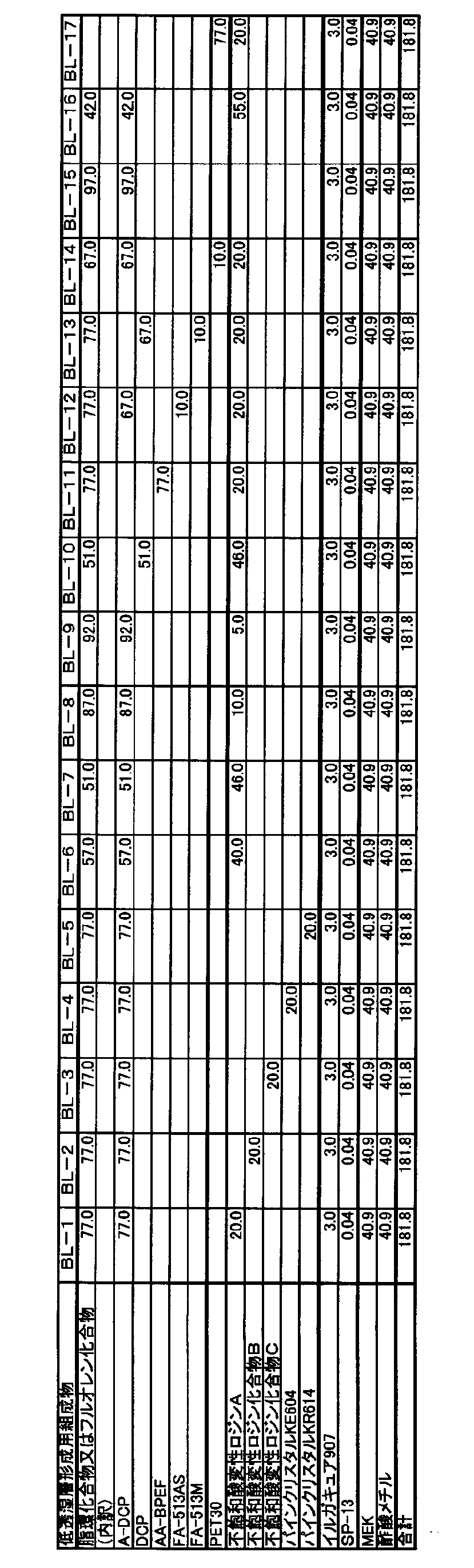
基材フィルムとしてフジタックTD60(富士フイルム(株)製、幅1,340mm、厚さ60μm)をロール形態から巻き出して、上記低透湿層形成用組成物BL-1を使用し、特開2006-122889号公報実施例1記載のスロットダイを用いたダイコート法で、搬送速度30m/分の条件で塗布し、60℃で150秒乾燥させた。その後、更に窒素パージ下酸素濃度約0.1%で出力160W/cmの空冷メタルハライドランプ(アイグラフィックス(株)製)を用いて、照度400mW/cm2、照射量120mJ/cm2の紫外線を照射して塗布層を硬化させ、巻き取った。低透湿層の膜厚は10μmになるよう塗布量を調整した。
得られた光学フィルムを光学フィルム101とした。
光学フィルム101の作製において、低透湿層形成用組成物を表1に記載のようにした以外は光学フィルム101と同様にして、光学フィルム102~117を作製した。
作製した各実施例及び比較例の光学フィルムについて膜厚を測定し、下記の物性測定と評価を行った。結果は下記表2に示す。
各実施例及び比較例の光学フィルム試料70mmφを40℃、相対湿度90%でそれぞれ24時間調湿し、JIS Z-0208記載の方法により測定した。
低透湿層の透湿度は、各光学フィルムの基材フィルムの透湿度を測定し、基材フィルムの透湿度と光学フィルムの透湿度から、明細書中で前述した式(1)を用いて算出した。
光学フィルムの低透湿層を有する側の表面に、カッターナイフで碁盤目状に縦11本、横11本の切り込みを入れて合計100個の1cm×1cmの大きさの正方形の升目を刻み、日東電工(株)製のポリエステル粘着テープ“NO.31B”を圧着して基材フィルムと塗布層の密着試験を行い、剥がれの有無を目視で観察した。
100個の升目中に剥がれが20升未満の場合は、同場所で密着試験を行った。繰り返し試験を最高2回行った。剥がれの有無を目視で観察し、下記の5段階評価を行った。
A:密着試験2回で100個の升目中に剥がれが全く認められなかったもの
B:密着試験2回で100個の升目中に剥がれが1~5升のもの
C:密着試験2回で100個の升目中に剥がれが6~19升のもの
D:密着試験2回で100個の升目中に剥がれが20升を超えたもの
E:密着試験1回で100個の升目中に剥がれが20升を超えたもの
<偏光板の作製>
1)フィルムの鹸化
市販のセルロースアシレートフィルム(フジタック ZRD40、富士フイルム(株)製)、市販のセルロースアシレートフィルムTD60(富士フィルム(株)製)と光学フィルム101~117を、55℃に保った1.5mol/LのNaOH水溶液(鹸化液)に2分間浸漬した後、フィルムを水洗し、その後、25℃の0.05mol/Lの硫酸水溶液に30秒浸漬した後、更に水洗浴を30秒流水下に通して、フィルムを中性の状態にした。そして、エアナイフによる水切りを3回繰り返し、水を落とした後に70℃の乾燥ゾーンに15秒間滞留させて乾燥し、鹸化処理したフィルムを作製した。
特開2001-141926号公報の実施例1に従い、延伸したポリビニルアルコールフィルムにヨウ素を吸着させて膜厚20μmの偏光子を作製した。
(フロント側偏光板101~117の作製)
上記の鹸化後の光学フィルム101~117(各光学フィルムの低透湿層を積層していない面を偏光子と接するように配置する)、上記で作製した偏光子、鹸化後のセルロースアシレートフィルムZRD40をこの順番で、PVA系接着剤で貼合し、熱乾燥して、偏光板101~117を作製した。
この際、作製した偏光子のロールの長手方向と光学フィルム101~117の長手方向とが平行になるように配置した。また、偏光子のロールの長手方向と上記セルロースアシレートフィルムZRD40のロールの長手方向とが、平行になるように配置した。
上記で作製した偏光子の片面に対して、アクリル接着剤を用いて、作製した光学フィルム101、102、115、117の低透湿層を積層した面を、コロナ処理を施したのち、貼合した。上記で作製した偏光子のもう片側にポリビニルアルコール系接着剤を用いて、上記鹸化した市販のセルロースアシレートフィルムZRD40を貼り付け、70℃で10分以上乾燥して、偏光板201、202、215、217を作製した。
この際、作製した偏光子のロールの長手方向と光学フィルム101、102、115、117の長手方向とが平行になるように配置した。また、偏光子のロールの長手方向と上記セルロースアシレートフィルムZRD40のロールの長手方向とが、平行になるように配置した。
得られた偏光板をそれぞれの偏光板201、202、215、217とした。
上記の鹸化後セルロースアシレートフィルムTD60、上記得られた延伸したヨウ素系PVA偏光子、鹸化後のセルロースアシレートフィルムZRD40をこの順番で、PVA系接着剤で貼合し、熱乾燥しリア側偏光板を得た。
この際、作製した偏光子のロールの長手方向とセルロースアシレートフィルムTD60の長手方向とが平行になるように配置した。また、偏光子のロールの長手方向と上記セルロースアシレートフィルムZRD40のロールの長手方向とが、平行になるように配置した。
IPSモード液晶セル(LGD製 42LS5600)の上下の偏光板を剥し、フロント側(視認側)に、フロント側偏光板として前述した偏光板101~117、201、202、215、217を、リア側にリア側偏光板として前述した偏光板を、セルロースアシレートフィルムZRD40がそれぞれ液晶セル側となるように、粘着剤を介して、フロント側及びリア側に一枚ずつ貼り付けた。フロント側の偏光板の吸収軸が長手方向(左右方向)に、そして、リア側の偏光板の透過軸が長手方向(左右方向)になるように、クロスニコル配置とした。液晶セルに使用されているガラスの厚さは0.5mmであった。
得られた液晶表示装置を、それぞれ液晶表示装置101~117、201、202、215、217とした。
なお、IPSパネルへの実装時における、フロント側偏光板の構成を下記表3に記載した。
このようにして作製した液晶表示装置101~117、201、202、215、217について、60℃相対湿度90%で48時間サーモ後、25℃相対湿度60%で2時間放置した後で液晶表示装置のバックライトを点灯し、点灯から5時間後と10時間後にパネルの四隅の光漏れを評価した。
光漏れ評価は、輝度計測用カメラ「ProMetric」(Radiant Imaging社製)で画面正面から黒表示画面を撮影し、全画面の平均輝度と、4角の光漏れが大きい箇所の輝度差をもとにして、7段階評価した。本発明においてAとBのレベルが許容内である。
~評価指標~
A:5時間後、パネル4角の光漏れが視認されない。
10時間後、パネル4角の光漏れが視認されない。
B:5時間後、パネル4角のうち、1~2角でわずかな光漏れが視認される。
10時間後、パネル4角の光漏れが視認されない。
C:5時間後、パネル4角のうち、1~2角でわずかな光漏れが視認される。
10時間後、パネル4角のうち、1~2角でわずかな光漏れが視認される。
D:5時間後、パネル4角のうち、3~4角でわずかな光漏れが視認される。
10時間後、パネル4角のうち、1~2角でわずかな光漏れが視認される。
E:5時間後、パネル4角のうち、3~4角でわずかな光漏れが視認される。
10時間後、パネル4角のうち、3~4角でわずかな光漏れが視認される。
F:5時間後、パネル4角の光漏れが強く、許容できない。
10時間後、パネル4角のうち、3~4角でわずかな光漏れが視認される。
G:5時間後、パネル4角で強い光漏れが視認される。
10時間後、パネル4角で強い光漏れが視認される。


1.光学フィルムの透湿度と高温高湿環境経時後の光漏れには強い相関があり、透湿度が低いほど光漏れを抑制することができる。
2.特定量の(A)環状脂肪族炭化水素基とエチレン性不飽和二重結合とを有する化合物及びフルオレン環とエチレン性不飽和二重結合とを有する化合物の少なくともいずれかと、特定量の(B)ロジン化合物とを低透湿層に用いた実施例101~114の光学フィルムは、膜厚が薄膜でありながら、透湿度が低く、好ましい。
3.(B)ロジン化合物の中でも、特に不飽和酸変性ロジンを用いたものは密着性にも優れており、特に好ましい。
4.本発明の光学フィルムを表示装置に実装した時の評価結果は、低透湿層と反対面を偏光子に貼合したものと、低透湿層を偏光子に貼合したものも同様の結果だった。本発明の光学フィルムは両面共に偏光子に貼合することができる。
[製造例3]
〔ハードコート層形成用組成物の調製〕
下記に示すように調製した。
PET30 97.0質量部
イルガキュア907 3.0質量部
SP-13 0.04質量部
MEK 81.8質量部
上記で作製したロール状の光学フィルム101をロール形態から巻き出して、上記ハードコート層形成用組成物HC-1を使用し、低透湿層を積層している面に、特開2006-122889号公報実施例1記載のスロットダイを用いたダイコート法で、搬送速度30m/分の条件で塗布し、60℃で150秒乾燥させた。その後、更に窒素パージ下酸素濃度約0.1%で出力160W/cmの空冷メタルハライドランプ(アイグラフィックス(株)製)を用いて、照度400mW/cm2、照射量300mJ/cm2の紫外線を照射して塗布層を硬化させ、巻き取った。ハードコート層の膜厚は8μmになるよう塗布量を調整した。
得られたフィルムを実施例の光学フィルム301とした。
光学フィルム101を光学フィルム117に変更した以外は光学フィルム301と同様にして比較例の光学フィルム317を作製した。
光学フィルムをフジタックTD60(富士フイルム(株)製、幅1,340mm、厚さ60μm)に変更した以外は光学フィルム301と同様にして比較例の光学フィルム320を作製した。
上記で作製したロール状の光学フィルム101をロール形態から巻き出して、上記ハードコート層形成用組成物HC-1を使用し、低透湿層を積層していない面に、特開2006-122889号公報実施例1記載のスロットダイを用いたダイコート法で、搬送速度30m/分の条件で塗布し、60℃で150秒乾燥させた。その後、更に窒素パージ下酸素濃度約0.1%で出力160W/cmの空冷メタルハライドランプ(アイグラフィックス(株)製)を用いて、照度400mW/cm2、照射量300mJ/cm2の紫外線を照射して塗布層を硬化させ、巻き取った。ハードコート層の膜厚は8μmになるよう塗布量を調整した。
得られたフィルムを実施例の光学フィルム401とした。
作製した各実施例及び比較例の光学フィルムについて膜厚を測定し、下記の物性測定と評価を行った。結果は下記表4に示す。
なお光学フィルムのハードコート層の膜厚はハードコート層の積層前後の膜厚を測定し、その差から求めた。また、光学フィルムの低透湿層の膜厚は低透湿層積層前後の膜厚を測定し、その差から求めた。
光学フィルム101と同様に、JIS Z-0208記載の方法により測定した。
(鉛筆硬度評価)
耐傷性の指標としてJIS K-5400に記載の鉛筆硬度評価を行った。光学フィルムを温度25℃、湿度60%RHで2時間調湿した後、JIS S 6006に規定する2H~5Hの試験用鉛筆を用いて、ハードコート層が積層された面を、4.9Nの荷重にて、以下のとおりの判定で評価し、OKとなる最も高い硬度を評価値とした。
OK:n=5の評価において傷なしが3つ以上
NG:n=5の評価において傷なしが2つ以下
<偏光板の作製>
1)フィルムの鹸化
市販のセルロースアシレートフィルム(フジタック ZRD40、富士フイルム(株)製)、市販のセルロースアシレートフィルムTD60(富士フィルム(株)製)と光学フィルム301、317、320を、55℃に保った1.5mol/LのNaOH水溶液(鹸化液)に2分間浸漬した後、フィルムを水洗し、その後、25℃の0.05mol/Lの硫酸水溶液に30秒浸漬した後、更に水洗浴を30秒流水下に通して、フィルムを中性の状態にした。そして、エアナイフによる水切りを3回繰り返し、水を落とした後に70℃の乾燥ゾーンに15秒間滞留させて乾燥し、鹸化処理したフィルムを作製した。
特開2001-141926号公報の実施例1に従い、延伸したポリビニルアルコールフィルムにヨウ素を吸着させて膜厚20μmの偏光子を作製した。
(フロント側偏光板301、317、320の作製)
上記の鹸化後の光学フィルム301、317、320(各光学フィルムの低透湿層を積層していない面を偏光子と接するように配置する)、上記で作製した偏光子、鹸化後のセルロースアシレートフィルムZRD40をこの順番で、PVA系接着剤で貼合し、熱乾燥して、偏光板301、317、320を作製した。
上記で作製した偏光子の片面に対して、アクリル接着剤を用いて、作製した光学フィルム401の低透湿層を積層した面を、コロナ処理を施したのち、貼合した。上記で作製した偏光子のもう片側にポリビニルアルコール系接着剤を用いて、上記鹸化した市販のセルロースアシレートフィルムZRD40を貼り付け、70℃で10分以上乾燥して、偏光板401を作製した。
上記の液晶表示装置101に対し、フロント側偏光板を偏光板101から偏光板301、317、320、401に代えた以外は同様にして液晶表示装置301、317、320、401を作製した。

光学フィルム301、317
基材フィルム/低透湿層/ハードコート層
光学フィルム320
基材フィルム/ハードコート層
光学フィルム401
低透湿層/基材フィルム/ハードコート層
表4に示す結果から以下のことが明らかである。
1.本発明の光学フィルムにハードコート層を積層することで、低透湿性に加えて高鉛筆硬度(3H)を付与することができる。
2.ハードコート層を低透湿層上に積層したもの(光学フィルム301)、ハードコート層と低透湿層を基材フィルムの対向面に配置したもの(光学フィルム401)は何れも鉛筆硬度、透湿度が同様に良好である。
次にパターンを形成した光学異方性層を含む本発明の態様について説明する。
(光学フィルムの片面鹸化処理)
上記作製した光学フィルム301を、温度60℃の誘電式加熱ロールを通過させ、フィルム表面温度を40℃に昇温した後に、ハードコート層が形成している面とは反対側の面に下記に示す組成のアルカリ溶液を、#6のワイヤーバーで連続的に塗布し、110℃に加熱し、ノリタケカンパニーリミテド社製のスチーム式遠赤外ヒーターの下に、10秒間搬送した。続いて、同じくバーコーターを用いて、純水を3ml/m2塗布した。次いで、ファウンテンコーターによる水洗とエアナイフによる水切りを3回繰り返した後に、70℃の乾燥ゾーンに10秒間搬送して乾燥し、光学フィルム301の片面をアルカリ鹸化処理した。
─────────────────────────────────
アルカリ溶液の組成
─────────────────────────────────
水酸化カリウム 2.0質量部
水 6.5質量部
イソプロパノール 85.0質量部
界面活性剤SF-1:C14H29O(CH2CH2O)20H
0.035質量部
プロピレングリコール 6.5質量部
─────────────────────────────────
上記アルカリ鹸化処理した光学フィルム301の、鹸化処理を施した面に、下記の組成の配向膜形成用塗布液1を#14のワイヤーバーで連続的に塗布した。60℃の温風で60秒、更に100℃の温風で120秒乾燥し、露光前配向膜付光学フィルム3011を形成した。露光前配向膜の膜厚は、0.45μmであり、酸素透過度は132cc/[m2・day・atom]であった。
─────────────────────────────────
配向膜形成用塗布液1の組成
─────────────────────────────────
下記配向膜用ポリマー材料(P-1) 2.4質量部
(重量平均分子量(Mw):20,000;下記式中の繰り返し単位の組成比は質量比である。)
下記光酸発生剤(S-1) 0.17質量部
ラジカル重合開始剤(イルガキュア2959、BASF社製)
0.18質量部
メタノール 16.5質量部
IPA(イソプロパノール) 7.2質量部
水 73.55質量部
─────────────────────────────────

次に、透過部の横ストライプ幅363μm、遮蔽部の横ストライプ幅363μmのストライプマスクを上記作製した露光前配向膜付光学フィルム3011上に配置し、室温(25℃)空気下にて、200nm~400nmの波長領域における照度500mW/cm2の紫外線照射装置(Light Hammer 10、240W/cm、Fusion UV Systems社製)を光源ユニットとして用いて紫外線を0.06秒間(30mJ/cm2)照射しパターン配向膜を形成した。
上記紫外線露光後のパターン配向膜に、ストライプマスクのストライプに対して45°の角度を保持して500rpmで一方向に1往復、ラビング処理を行った。次いで、下記の光学異方性層用塗布液を、ワイヤーバーで硬化後の膜厚が1.2μmになるように調整して塗布した。更に、膜面温度110℃で2分間加熱熟成した後、80℃まで冷却し空気下にて20mW/cm2の空冷メタルハライドランプ(アイグラフィックス社製)を用いて紫外線を20秒間照射して、その配向状態を固定化することによりパターン光学異方性層を形成した。マスク露光部分(第1位相差領域)は、ラビング方向に対し遅相軸方向が平行にディスコティック液晶化合物が垂直配向しており、未露光部分(第2位相差領域)は直交に垂直配向していた。
光学異方性層用塗布液の組成
─────────────────────────────────
ディスコティック液晶化合物E-2 100質量部
配向膜界面配向剤(II-1) 1.0質量部
空気界面配向剤(P-2) 0.4質量部
光重合開始剤 3.0質量部
(イルガキュア907、BASF社製)
増感剤(カヤキュア-DETX、日本化薬(株)製) 1.0質量部
メチルエチルケトン 400質量部
─────────────────────────────────

(光学フィルム501の作製)
以上のようにして、基材フィルムの両面にそれぞれハードコート層とパターン光学異方性層が形成された、本発明の光学フィルム501を作製した。
光学フィルム301を本発明の低透湿層を積層していない光学フィルム320に代えた以外は光学フィルム501と同様にして支持体の両面にそれぞれハードコート層とパターン光学異方性層が形成された、比較例の光学フィルム502を作製した。
フロント側偏光板401と同様に偏光子と鹸化後のセルロースアシレートフィルムZRD40をPVA系接着剤で貼合した、偏光子の片面に、光学フィルム501のパターン光学異方性層を形成した面をアクリル系粘着剤で貼合し、フロント側偏光板501を作製した。
光学フィルム501を光学フィルム502に代えた以外は同様にして、フロント側偏光版502を作製した。
上記の液晶表示装置101に対し、フロント側偏光板を偏光板101から、偏光板501、502に代えた以外は同様にして液晶表示装置501、502を作製した。
液晶表示装置501はA、液晶表示装置502はGであった。これにより、パターンを形成した光学異方性層を含む態様においても光漏れを防止することができ、好ましいことが分かった。
次に光ラジカル硬化系配向膜を有するパターンを形成した光学異方性層を含む本発明の態様について説明する。
特表2012-517024号公報(WO2010/090429号公報)の実施例を参考した。光学フィルム301のハードコート層積層していない面に、乾燥厚さが1000Å(オングストローム)であるポリノルボルネン含有配向膜を形成した。
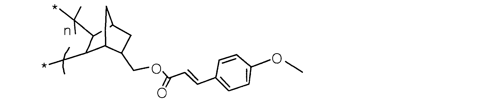
化学式1のシンナメート基を有するポリノルボルネン 20.0質量部
ペンタエリスリトールトリアクリレート 10.0質量部
イルガキュア907 5.0質量部
シクロヘキサノン 980.0質量部
光学フィルム511に対して、光学フィルム301を光学フィルム401に代えて、配向膜を低透湿層上に積層した以外は光学フィルム511と同様にして光学フィルム512を作製した。
光学フィルム511に対して、光学フィルム301を光学フィルム320に代えた以外は同様にして、光学フィルム513を作製した。
光学フィルムを511、512、513に代えた以外はフロント側偏光板501と同様にして、フロント側偏光板511、512、513を作製した。
上記の液晶表示装置101に対し、フロント側偏光板を偏光板101から、偏光板511、512、513に代えた以外は同様にして液晶表示装置511、512、513を作製した。
液晶表示装置511と液晶表示装置512はA、液晶表示装置513はGであった。これにより、パターンを形成した光学異方性層を含む態様においても本発明の低透湿層を積層した光学フィルムは光漏れを防止することができ、好ましいことが分かった。
次に、基材フィルムとしてアクリル系フィルムを用いた実施例を示す。
<基材フィルム(A-1)の作製>
攪拌装置、温度センサー、冷却管及び窒素導入管を備えた内容積30Lの反応釜に、メタクリル酸メチル(MMA)8000g、2-(ヒドロキシメチル)アクリル酸メチル(MHMA)2000g及び重合のための溶剤としてトルエン10000gを仕込み、これに窒素を通じつつ、105℃まで昇温させた。昇温に伴う環流が始まったところで、重合開始剤としてt-アミルパーオキシイソノナノエート10.0gを添加するとともに、t-アミルパーオキシイソノナノエート20.0gとトルエン100gとからなる溶液を2時間かけて滴下しながら、約105~110℃の環流下で溶液重合を進行させ、更に4時間の熟成を行った。重合反応率は96.6%、得られた重合体におけるMHMAの含有率(重量比)は20.0%であった。
攪拌装置、温度センサー、冷却管及び窒素導入管を備えた内容積30Lの反応釜に、41.5質量部のメタクリル酸メチル(MMA)、6質量部の2-(ヒドロキシメチル)アクリル酸メチル(MHMA)、2.5質量部の2-〔2’-ヒドロキシ-5’-メタクリロイルオキシ〕エチルフェニル〕-2H-ベンゾトリアゾール(大塚化学製、商品名:RUVA-93)、重合のための溶剤として50質量部のトルエン、0.025質量部の酸化防止剤(旭電化工業製、アデカスタブ2112)、及び連鎖移動剤として0.025質量部のn-ドデシルメルカプタンを仕込み、これに窒素を通じつつ、105℃まで昇温させた。昇温に伴う還流が始まったところで、重合開始剤として0.05質量部のt-アミルパーオキシイソノナノエート(アルケマ吉富製、商品名:ルペロックス570)を添加するとともに、0.10質量部のt-アミルパーオキシイソノナノエートを3時間かけて滴下しながら、約105~110℃の還流下で溶液重合を進行させ、更に4時間の熟成を行った。
このようにして得た二軸延伸性の樹脂フィルムの物性を測定したところ、厚さは40μm、ヘイズ(濁度)は0.3%、ガラス転移温度は128℃、380nmの光に対する透過率は5.8%、500nmの光に対する透過率は92.2%であった。
A-DCP 77.0質量部
不飽和酸変性ロジンA(酸価342mgKOH/g)20.0質量部
イルガキュア907 3.0質量部
SP-13 0.04質量部
MEK 82.0質量部
低透湿層形成用組成物BL-21の固形分濃度は55質量%であった。
A-DCP 97.0質量部
イルガキュア907 3.0質量部
SP-13 0.04質量部
MEK 82.0質量部
低透湿層形成用組成物BL-22の固形分濃度は55質量%であった。
基材フィルム(A-1)をロール形態から巻き出して、上記低透湿層形成用組成物BL-21を使用し、特開2006-122889号公報実施例1記載のスロットダイを用いたダイコート法で、搬送速度30m/分の条件で塗布し、60℃で150秒乾燥させた。その後、更に窒素パージ下酸素濃度約0.1%で出力160W/cmの空冷メタルハライドランプ(アイグラフィックス(株)製)を用いて、照度400mW/cm2、照射量120mJ/cm2の紫外線を照射して塗布層を硬化させ、巻き取った。低透湿層の膜厚は10μmになるよう塗布量を調整した。
得られた光学フィルムを光学フィルム601とした。
光学フィルム601の作製において、基材フィルムと低透湿層形成用組成物を下記表に記載のようにした以外は光学フィルム601と同様にして、光学フィルム602~604を作製した。

基材フィルムをアクリル系フィルムにした場合もセルロースアシレートを基材フィルムとした場合と同様に特定量の(A)環状脂肪族炭化水素基とエチレン性不飽和二重結合とを有する化合物及びフルオレン環とエチレン性不飽和二重結合とを有する化合物の少なくともいずれかと、特定量の(B)ロジン化合物とを含有する低透湿層を有する光学フィルムは、それを有しない光学フィルムに対し、透湿度が低く、好ましい態様の一つである。
次に、基材フィルムとしてセルロースアシレートフィルム上に密着層を積層したものを用いた実施例を示す。
(密着層形成用塗布液AL-1の組成)
A-TMMT 3.39質量部
イルガキュア907 0.11質量部
SP-13 0.0007質量部
MEK 18.17質量部
MIBK 77.20質量部
・A-TMMT:ペンタエリスリトールテトラアクリレート[新中村化学工業(株)製]
得られた光学フィルムを基材フィルム(B-1)とした。
A-DCP 38.5質量部
DCP 38.5質量部
不飽和酸変性ロジンA(酸価342mgKOH/g) 20.0質量部
イルガキュア907 3.0質量部
SP-13 0.04質量部
MEK 82.0質量部
低透湿層形成用組成物BL-23の固形分濃度は55質量%であった。
A-DCP 43.5質量部
DCP 43.5質量部
水添ロジンD(酸価176mgKOH/g) 10.0質量部
イルガキュア907 3.0質量部
SP-13 0.04質量部
MEK 82.0質量部
低透湿層形成用組成物BL-24の固形分濃度は55質量%であった。
A-DCP 46.0質量部
DCP 46.0質量部
パインクリスタルKR614 15.0質量部
イルガキュア907 3.0質量部
SP-13 0.04質量部
MEK 82.0質量部
低透湿層形成用組成物BL-25の固形分濃度は55質量%であった。
基材フィルム(B-1)をロール形態から巻き出して、上記低透湿層形成用組成物BL-21を使用し、密着層を積層した面に、特開2006-122889号公報実施例1記載のスロットダイを用いたダイコート法で、搬送速度30m/分の条件で塗布し、60℃で150秒乾燥させた。その後、更に窒素パージ下酸素濃度約0.1%で出力160W/cmの空冷メタルハライドランプ(アイグラフィックス(株)製)を用いて、照度400mW/cm2、照射量120mJ/cm2の紫外線を照射して塗布層を硬化させ、巻き取った。低透湿層の膜厚は9μmになるよう塗布量を調整した。
得られた光学フィルムを光学フィルム701とした。
光学フィルム701の作製において、低透湿層形成用組成物BL-21をBL-22~BL-25に変えた以外は光学フィルム701と同様にして、光学フィルム702~705を作製した。
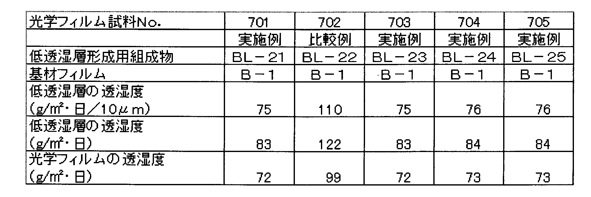
基材フィルムをセルロースアシレートフィルム上に密着層を積層したものにした場合も密着層のないセルロースアシレートを基材フィルムとした場合と同様に特定量の(A)環状脂肪族炭化水素基とエチレン性不飽和二重結合とを有する化合物及びフルオレン環とエチレン性不飽和二重結合とを有する化合物の少なくともいずれかと、特定量の(B)ロジン化合物とを含有する低透湿層を有する光学フィルムは、それを有しない光学フィルムに対し、透湿度が低く、好ましい態様の一つである。
次に、製造例7で示した本発明の光学フィルムに防眩層を積層したものを示す。
下記に示すように調製した。
スメクタイト 1.00質量部
(ルーセンタイトSTN、コープケミカル社製)
架橋アクリル-スチレン粒子 8.00質量部
(平均粒径2.5μm 屈折率1.52)
アクリレートモノマー 87.85質量部
(NKエステルA9550、新中村化学工業社製)
イルガキュア907 3.00質量部
レベリング剤(SP-13) 0.15質量部
MIBK(メチルイソブチルケトン) 133.50質量部
MEK(メチルエチルケトン) 16.50質量部
上記で作製した光学フィルム701をロール形態で巻き出して、上記防眩性ハードコート層用組成物(AGL-1)を使用し、低屈折率層を積層した面に、特開2006-122889号公報実施例1記載のスロットダイを用いたダイコート法で、搬送速度30m/分の条件で塗布し、60℃で150秒乾燥させた。その後、更に窒素パージ下酸素濃度約0.1%で出力160W/cmの空冷メタルハライドランプ(アイグラフィックス(株)製)を用いて、照度400mW/cm2、照射量180mJ/cm2の紫外線を照射して塗布層を硬化させ、巻き取った。防眩層の膜厚は6μmになるよう塗布量を調整した。
得られた光学フィルムを光学フィルム801とした。
光学フィルム801の作製において、光学フィルム701を702~705に変えた以外は光学フィルム701と同様にして、光学フィルム802~805を作製した。

低透湿層上に防眩性ハードコート層を積層した場合も防眩性ハードコート層を積層していないものと同様、特定量の(A)環状脂肪族炭化水素基とエチレン性不飽和二重結合とを有する化合物及びフルオレン環とエチレン性不飽和二重結合とを有する化合物の少なくともいずれかと、特定量の(B)ロジン化合物とを含有する低透湿層を有する光学フィルムは、それを有しない光学フィルムに対し、透湿度が低く、好ましい態様の一つである。
また、低透湿層上に防眩性ハードコート層を積層したものは、防眩性ハードコート層を積層していないものに対し、防眩性が付与される。
本出願は、2013年2月1日出願の日本特許出願(特願2013-019006)、2013年2月28日出願の日本特許出願(特願2013-039688)及び2013年4月24日出願の日本特許出願(特願2013-091812)に基づくものであり、その内容はここに参照として取り込まれる。
Claims (13)
- 基材フィルム上に、硬化性組成物の全固形分を100質量%としたときに、全固形分に対して下記(A)を50~99質量%及び下記(B)を1~50質量%含有する硬化性組成物を硬化して形成される層を有する光学フィルム。
(A)環状脂肪族炭化水素基とエチレン性不飽和二重結合とを有する化合物及びフルオレン環とエチレン性不飽和二重結合とを有する化合物の少なくともいずれか
(B)ロジン化合物 - 上記環状脂肪族炭化水素基が下記一般式(I)で表される基である請求項1に記載の光学フィルム。

一般式(I)中、L、及びL’は各々独立に二価以上の連結基を表し、nは1~3の整数を表す。 - 前記ロジン化合物が、ロジン、水添ロジン、酸変性ロジン及びエステル化ロジンから選ばれる1種以上のロジン化合物である、請求項1又は2に記載の光学フィルム。
- 前記ロジン化合物が酸変性ロジンである、請求項1~3のいずれか1項に記載の光学フィルム。
- 前記光学フィルムの透湿度が5.0~100g/m2/dayである、請求項1~4のいずれか1項に記載の光学フィルム。
(ここで、光学フィルムの透湿度は、JIS Z-0208の手法で、40℃、相対湿度90%で24時間経過後の値である。) - 前記(A)及び(B)を含有する層の透湿度が5.0~100g/m2/dayである、請求項1~5のいずれか1項に記載の光学フィルム。
(ここで、透湿度は、JIS Z-0208の手法で、40℃、相対湿度90%で24時間経過後の値である。前記(A)及び(B)を含有する層の透湿度以下の式(1)によって算出される。
1/Jf=1/Js+1/Jb ・・・・・ 式(1)
上記式(1)中、Jbは光学フィルムを基材フィルムと、前記(A)及び(B)を含有する層とに分離したときの前記層の透湿度を表し、光学フィルムの透湿度をJf、基材フィルムの透湿度をJsとする。) - 前記(A)及び(B)を含有する層の膜厚10μmであるときの前記(A)及び(B)を含有する層の換算透湿度が、5.0~100g/m2/dayである、請求項1~6のいずれか1項に記載の光学フィルム。
(ここで、透湿度は、JIS Z-0208の手法で、40℃、相対湿度90%で24時間経過後の値である。膜厚10μmの前記(A)及び(B)を含有する層の透湿度以下の式(2)によって算出される。
Jb×db/10 ・・・・・ 式(2)
上記式(2)中、Jbは光学フィルムを基材フィルムと、前記(A)及び(B)を含有する層とに分離したときの前記層の透湿度を表し、db[μm]は低透湿層の膜厚を表す。) - 前記基材フィルムがセルロースアシレートフィルムである請求項1~7のいずれか1項に記載の光学フィルム。
- 前記基材フィルムが主鎖にラクトン環構造、無水グルタル酸環構造、及びグルタルイミド環構造のいずれか少なくとも1種を有する(メタ)アクリル系重合体である、請求項1~7のいずれか1項に記載の光学フィルム。
- 前記光学フィルムが前記(A)及び(B)を含有する層上にハードコート層を更に有する、請求項1~9のいずれか1項に記載の光学フィルム。
- 基材フィルム上に下記(A)及び(B)を含有する硬化性組成物を硬化して層を形成する工程を有する光学フィルムの製造方法。
(A)環状脂肪族炭化水素基とエチレン性不飽和二重結合とを有する化合物及びフルオレン環とエチレン性不飽和二重結合とを有する化合物の少なくともいずれかを前記硬化性組成物の全固形分を100質量%としたときに、全固形分に対し50~99質量%
(B)ロジン化合物を前記硬化性組成物の全固形分に対し1~50質量% - 偏光子と、
該偏光子の保護フィルムとして請求項1~10のいずれか1項に記載の光学フィルムとを少なくとも1枚含む偏光板。 - 液晶セルと、
該液晶セルの少なくとも一方に配置された請求項12に記載の偏光板とを含み、
前記光学フィルムが最表層となるように配置された液晶表示装置。
Priority Applications (3)
| Application Number | Priority Date | Filing Date | Title |
|---|---|---|---|
| KR1020157020600A KR20150100931A (ko) | 2013-02-01 | 2014-01-24 | 광학 필름 및 그 제조 방법, 편광판 그리고 액정 표시 장치 |
| JP2014559656A JPWO2014119487A1 (ja) | 2013-02-01 | 2014-01-24 | 光学フィルム及びその製造方法、偏光板並びに液晶表示装置 |
| US14/812,477 US10012770B2 (en) | 2013-02-01 | 2015-07-29 | Optical film, method of manufacturing the same, polarizing plate and liquid crystal display device |
Applications Claiming Priority (6)
| Application Number | Priority Date | Filing Date | Title |
|---|---|---|---|
| JP2013-019006 | 2013-02-01 | ||
| JP2013019006 | 2013-02-01 | ||
| JP2013039688 | 2013-02-28 | ||
| JP2013-039688 | 2013-02-28 | ||
| JP2013091812 | 2013-04-24 | ||
| JP2013-091812 | 2013-04-24 |
Related Child Applications (1)
| Application Number | Title | Priority Date | Filing Date |
|---|---|---|---|
| US14/812,477 Continuation US10012770B2 (en) | 2013-02-01 | 2015-07-29 | Optical film, method of manufacturing the same, polarizing plate and liquid crystal display device |
Publications (1)
| Publication Number | Publication Date |
|---|---|
| WO2014119487A1 true WO2014119487A1 (ja) | 2014-08-07 |
Family
ID=51262202
Family Applications (1)
| Application Number | Title | Priority Date | Filing Date |
|---|---|---|---|
| PCT/JP2014/051546 Ceased WO2014119487A1 (ja) | 2013-02-01 | 2014-01-24 | 光学フィルム及びその製造方法、偏光板並びに液晶表示装置 |
Country Status (5)
| Country | Link |
|---|---|
| US (1) | US10012770B2 (ja) |
| JP (1) | JPWO2014119487A1 (ja) |
| KR (1) | KR20150100931A (ja) |
| TW (1) | TW201434630A (ja) |
| WO (1) | WO2014119487A1 (ja) |
Cited By (14)
| Publication number | Priority date | Publication date | Assignee | Title |
|---|---|---|---|---|
| WO2016009743A1 (ja) * | 2014-07-16 | 2016-01-21 | コニカミノルタ株式会社 | 光学フィルム、偏光板および画像表示装置 |
| WO2016013261A1 (ja) * | 2014-07-24 | 2016-01-28 | コニカミノルタ株式会社 | 光学フィルム、偏光板および画像表示装置 |
| WO2016035404A1 (ja) * | 2014-09-05 | 2016-03-10 | コニカミノルタ株式会社 | 光学フィルム、偏光板および画像表示装置 |
| JP2016141147A (ja) * | 2015-02-05 | 2016-08-08 | 株式会社ブリヂストン | 積層体及び導電性ローラ |
| WO2017057348A1 (ja) * | 2015-09-29 | 2017-04-06 | 富士フイルム株式会社 | 転写フィルム、静電容量型入力装置の電極保護膜、積層体、積層体の製造方法および静電容量型入力装置 |
| WO2017104616A1 (ja) * | 2015-12-14 | 2017-06-22 | 富士フイルム株式会社 | 光学フィルム、偏光板、および画像表示装置 |
| JP2017111212A (ja) * | 2015-12-14 | 2017-06-22 | 富士フイルム株式会社 | 光学フィルム、偏光板、および画像表示装置 |
| JP2017111211A (ja) * | 2015-12-14 | 2017-06-22 | 富士フイルム株式会社 | 光学フィルム、偏光板、および画像表示装置 |
| JP2018016015A (ja) * | 2016-07-29 | 2018-02-01 | 富士フイルム株式会社 | 積層体、光学フィルム、偏光板保護フィルム、偏光板及び画像表示装置 |
| KR101861910B1 (ko) * | 2015-01-23 | 2018-05-28 | 삼성에스디아이 주식회사 | 편광판용 접착제, 편광판 및 표시장치 |
| KR20180060028A (ko) * | 2016-11-28 | 2018-06-07 | 주식회사 엘지화학 | 광학용 필름을 포함하는 편광판 |
| JPWO2019130828A1 (ja) * | 2017-12-27 | 2020-12-03 | 富士フイルム株式会社 | 包装材およびその使用方法 |
| JPWO2021192615A1 (ja) * | 2020-03-27 | 2021-09-30 | ||
| JP2023128389A (ja) * | 2022-03-03 | 2023-09-14 | 株式会社日本触媒 | ドープ、フィルム、及びフィルムの製造方法 |
Families Citing this family (6)
| Publication number | Priority date | Publication date | Assignee | Title |
|---|---|---|---|---|
| KR101882044B1 (ko) * | 2011-04-01 | 2018-07-25 | 쓰리엠 이노베이티브 프로퍼티즈 캄파니 | 트라이아진계 자외선 흡수제를 포함하는 필름 |
| US10384959B2 (en) * | 2014-07-03 | 2019-08-20 | Shlomo Nir | Method of making and using granulated micelle-clay complexes for removal of pollutants from water |
| JP2017009795A (ja) * | 2015-06-22 | 2017-01-12 | 日東電工株式会社 | 偏光板及び偏光板の製造方法 |
| KR102463863B1 (ko) * | 2015-07-20 | 2022-11-04 | 삼성전자주식회사 | 연마용 조성물 및 이를 이용한 반도체 장치의 제조 방법 |
| KR20180055178A (ko) * | 2016-11-16 | 2018-05-25 | 동우 화인켐 주식회사 | 터치 센서용 접착제 조성물 및 이를 이용한 광학 적층체 |
| CN110183803B (zh) * | 2019-06-12 | 2020-08-11 | 四川大学 | 一种透明介电薄膜及其制备方法 |
Citations (5)
| Publication number | Priority date | Publication date | Assignee | Title |
|---|---|---|---|---|
| JPH11216817A (ja) * | 1998-01-30 | 1999-08-10 | Nippon Zeon Co Ltd | 複合フィルム |
| JP2002146044A (ja) * | 2000-11-07 | 2002-05-22 | Konica Corp | セルロースエステルフィルム及び偏光板用保護フィルム |
| JP2006083225A (ja) * | 2004-09-14 | 2006-03-30 | Fuji Photo Film Co Ltd | 機能性フィルム |
| WO2010110254A1 (ja) * | 2009-03-24 | 2010-09-30 | 日本カーバイド工業株式会社 | 粘着剤組成物 |
| JP2011215628A (ja) * | 2010-03-16 | 2011-10-27 | Sekisui Chem Co Ltd | 透明複合シート、積層シート及び液晶表示素子 |
Family Cites Families (16)
| Publication number | Priority date | Publication date | Assignee | Title |
|---|---|---|---|---|
| US6762735B2 (en) | 2000-05-12 | 2004-07-13 | Semiconductor Energy Laboratory Co., Ltd. | Electro luminescence display device and method of testing the same |
| US7125918B2 (en) | 2000-11-07 | 2006-10-24 | Konica Corporation | Protective film of a polarizing plate |
| JP2003183417A (ja) * | 2001-12-25 | 2003-07-03 | Konica Corp | セルロースエステルフィルム及び偏光板用保護フィルム |
| JPWO2006112207A1 (ja) * | 2005-03-31 | 2008-12-04 | 株式会社日本触媒 | 偏光子保護フィルム、偏光板、および画像表示装置 |
| JP2006292834A (ja) * | 2005-04-06 | 2006-10-26 | Fuji Photo Film Co Ltd | 偏光板用保護フィルム、偏光板および液晶表示装置 |
| JP2007119720A (ja) | 2005-09-29 | 2007-05-17 | Dainippon Printing Co Ltd | 硬化性樹脂組成物 |
| JP5201816B2 (ja) * | 2006-10-06 | 2013-06-05 | 東洋インキScホールディングス株式会社 | 接着性樹脂組成物および接着性フィルム |
| JP2008249896A (ja) * | 2007-03-29 | 2008-10-16 | Fujifilm Corp | 偏光板用保護フィルム、偏光板、及び液晶表示装置 |
| WO2008153143A1 (ja) | 2007-06-14 | 2008-12-18 | Nippon Shokubai Co., Ltd. | 熱可塑性樹脂組成物とそれを用いた樹脂成形品および偏光子保護フィルムならびに樹脂成形品の製造方法 |
| JP2009098653A (ja) | 2007-09-27 | 2009-05-07 | Nitto Denko Corp | 偏光板、光学フィルムおよび画像表示装置 |
| JP4379547B2 (ja) | 2007-10-13 | 2009-12-09 | コニカミノルタオプト株式会社 | 光学フィルムの製造方法 |
| US7709572B2 (en) | 2007-10-13 | 2010-05-04 | Konica Minolta Opto, Inc. | Optical film, polarizing plate and display device using the same, and manufacturing method thereof |
| JP2010254890A (ja) * | 2009-04-28 | 2010-11-11 | Hitachi Chem Co Ltd | 光硬化性樹脂組成物及びそれを用いた光硬化性防湿絶縁塗料、電子部品、フラットパネルディスプレイ |
| KR20110114472A (ko) | 2010-04-13 | 2011-10-19 | 후지필름 가부시키가이샤 | 셀룰로오스아실레이트 필름, 편광판 및 액정 표시 장치 |
| WO2012020750A1 (ja) * | 2010-08-10 | 2012-02-16 | 東洋紡績株式会社 | 樹脂組成物、及びそれを用いてなる金属被覆体、並びに接着剤 |
| TWI506110B (zh) * | 2011-05-30 | 2015-11-01 | Cheil Ind Inc | 黏合劑組合物、光學元件和黏合劑片 |
-
2014
- 2014-01-24 KR KR1020157020600A patent/KR20150100931A/ko not_active Ceased
- 2014-01-24 JP JP2014559656A patent/JPWO2014119487A1/ja active Pending
- 2014-01-24 WO PCT/JP2014/051546 patent/WO2014119487A1/ja not_active Ceased
- 2014-01-28 TW TW103103032A patent/TW201434630A/zh unknown
-
2015
- 2015-07-29 US US14/812,477 patent/US10012770B2/en active Active
Patent Citations (5)
| Publication number | Priority date | Publication date | Assignee | Title |
|---|---|---|---|---|
| JPH11216817A (ja) * | 1998-01-30 | 1999-08-10 | Nippon Zeon Co Ltd | 複合フィルム |
| JP2002146044A (ja) * | 2000-11-07 | 2002-05-22 | Konica Corp | セルロースエステルフィルム及び偏光板用保護フィルム |
| JP2006083225A (ja) * | 2004-09-14 | 2006-03-30 | Fuji Photo Film Co Ltd | 機能性フィルム |
| WO2010110254A1 (ja) * | 2009-03-24 | 2010-09-30 | 日本カーバイド工業株式会社 | 粘着剤組成物 |
| JP2011215628A (ja) * | 2010-03-16 | 2011-10-27 | Sekisui Chem Co Ltd | 透明複合シート、積層シート及び液晶表示素子 |
Cited By (21)
| Publication number | Priority date | Publication date | Assignee | Title |
|---|---|---|---|---|
| WO2016009743A1 (ja) * | 2014-07-16 | 2016-01-21 | コニカミノルタ株式会社 | 光学フィルム、偏光板および画像表示装置 |
| WO2016013261A1 (ja) * | 2014-07-24 | 2016-01-28 | コニカミノルタ株式会社 | 光学フィルム、偏光板および画像表示装置 |
| WO2016035404A1 (ja) * | 2014-09-05 | 2016-03-10 | コニカミノルタ株式会社 | 光学フィルム、偏光板および画像表示装置 |
| KR101861910B1 (ko) * | 2015-01-23 | 2018-05-28 | 삼성에스디아이 주식회사 | 편광판용 접착제, 편광판 및 표시장치 |
| JP2016141147A (ja) * | 2015-02-05 | 2016-08-08 | 株式会社ブリヂストン | 積層体及び導電性ローラ |
| WO2017057348A1 (ja) * | 2015-09-29 | 2017-04-06 | 富士フイルム株式会社 | 転写フィルム、静電容量型入力装置の電極保護膜、積層体、積層体の製造方法および静電容量型入力装置 |
| CN108025533B (zh) * | 2015-09-29 | 2022-10-21 | 富士胶片株式会社 | 转印薄膜、静电电容型输入装置及其电极保护膜、层叠体及其制造方法 |
| US10795515B2 (en) | 2015-09-29 | 2020-10-06 | Fujifilm Corporation | Transfer film, electrode protective film for electrostatic capacitance-type input device, laminate, method for manufacturing laminate, and electrostatic capacitance-type input device |
| JPWO2017057348A1 (ja) * | 2015-09-29 | 2018-08-16 | 富士フイルム株式会社 | 転写フィルム、静電容量型入力装置の電極保護膜、積層体、積層体の製造方法および静電容量型入力装置 |
| CN108025533A (zh) * | 2015-09-29 | 2018-05-11 | 富士胶片株式会社 | 转印薄膜、静电电容型输入装置的电极保护膜、层叠体、层叠体的制造方法及静电电容型输入装置 |
| WO2017104616A1 (ja) * | 2015-12-14 | 2017-06-22 | 富士フイルム株式会社 | 光学フィルム、偏光板、および画像表示装置 |
| JP2017111211A (ja) * | 2015-12-14 | 2017-06-22 | 富士フイルム株式会社 | 光学フィルム、偏光板、および画像表示装置 |
| JP2017111212A (ja) * | 2015-12-14 | 2017-06-22 | 富士フイルム株式会社 | 光学フィルム、偏光板、および画像表示装置 |
| JP2018016015A (ja) * | 2016-07-29 | 2018-02-01 | 富士フイルム株式会社 | 積層体、光学フィルム、偏光板保護フィルム、偏光板及び画像表示装置 |
| KR20180060028A (ko) * | 2016-11-28 | 2018-06-07 | 주식회사 엘지화학 | 광학용 필름을 포함하는 편광판 |
| KR102034735B1 (ko) | 2016-11-28 | 2019-10-21 | 주식회사 엘지화학 | 광학용 필름을 포함하는 편광판 |
| JPWO2019130828A1 (ja) * | 2017-12-27 | 2020-12-03 | 富士フイルム株式会社 | 包装材およびその使用方法 |
| JPWO2021192615A1 (ja) * | 2020-03-27 | 2021-09-30 | ||
| WO2021192615A1 (ja) * | 2020-03-27 | 2021-09-30 | 日東電工株式会社 | 偏光フィルム、画像表示装置及び偏光フィルムの製造方法 |
| JP7610581B2 (ja) | 2020-03-27 | 2025-01-08 | 日東電工株式会社 | 偏光フィルム、画像表示装置及び偏光フィルムの製造方法 |
| JP2023128389A (ja) * | 2022-03-03 | 2023-09-14 | 株式会社日本触媒 | ドープ、フィルム、及びフィルムの製造方法 |
Also Published As
| Publication number | Publication date |
|---|---|
| US10012770B2 (en) | 2018-07-03 |
| US20150331151A1 (en) | 2015-11-19 |
| JPWO2014119487A1 (ja) | 2017-01-26 |
| TW201434630A (zh) | 2014-09-16 |
| KR20150100931A (ko) | 2015-09-02 |
Similar Documents
| Publication | Publication Date | Title |
|---|---|---|
| WO2014119487A1 (ja) | 光学フィルム及びその製造方法、偏光板並びに液晶表示装置 | |
| JP5914440B2 (ja) | ハードコートフィルム、ハードコートフィルムの製造方法、反射防止フィルム、偏光板、及び画像表示装置 | |
| KR101701076B1 (ko) | 액정 표시 장치 | |
| JP2014170130A (ja) | 光学フィルム及びその製造方法、偏光板ならびに液晶表示装置 | |
| JP6086629B2 (ja) | 光学フィルム、光学フィルムの製造方法、偏光板、及び画像表示装置 | |
| JP6086607B2 (ja) | 低透湿性フィルム、光学フィルム、偏光板、及び液晶表示装置、並びに低透湿性フィルムの製造方法 | |
| JP2015102813A (ja) | 偏光板保護フィルム、偏光板保護フィルムの製造方法、偏光板、及び画像表示装置 | |
| WO2015053359A1 (ja) | 偏光板、画像表示装置 | |
| JP6412807B2 (ja) | 偏光板及び液晶表示装置 | |
| JP2014170202A (ja) | 液晶表示装置 | |
| JP6053729B2 (ja) | 偏光板保護フィルム、偏光板、及び液晶表示装置、並びに偏光板保護フィルムの製造方法 | |
| JP2016033623A (ja) | 光学フィルム及びその製造方法、偏光板並びに液晶表示装置 | |
| JPWO2012026245A1 (ja) | ハードコートフィルム、偏光板及び液晶表示装置 | |
| JP2015022200A (ja) | 液晶表示装置 | |
| KR20140047548A (ko) | 광학 필름 및 그 제조 방법, 편광판 및 액정 표시 장치 | |
| JP2014095730A (ja) | 光学フィルム及びその製造方法、偏光板ならびに液晶表示装置 | |
| WO2014057950A1 (ja) | 光学フィルム、光学フィルムの製造方法、偏光板、及び画像表示装置 | |
| WO2014133147A1 (ja) | 光学フィルム、偏光板および画像表示装置 | |
| JP2015197503A (ja) | 偏光板保護フィルム、偏光板、及び液晶表示装置、並びに偏光板保護フィルムの製造方法 | |
| JP2006251163A (ja) | 反射防止フィルム、偏光板及びこれらを用いた画像表示装置 | |
| JP2014098893A (ja) | 光学フィルム及びその製造方法、偏光板ならびに液晶表示装置 |
Legal Events
| Date | Code | Title | Description |
|---|---|---|---|
| 121 | Ep: the epo has been informed by wipo that ep was designated in this application |
Ref document number: 14746646 Country of ref document: EP Kind code of ref document: A1 |
|
| ENP | Entry into the national phase |
Ref document number: 2014559656 Country of ref document: JP Kind code of ref document: A |
|
| ENP | Entry into the national phase |
Ref document number: 20157020600 Country of ref document: KR Kind code of ref document: A |
|
| NENP | Non-entry into the national phase |
Ref country code: DE |
|
| 122 | Ep: pct application non-entry in european phase |
Ref document number: 14746646 Country of ref document: EP Kind code of ref document: A1 |