WO2014115478A1 - 生体試料用インピーダンス測定装置および生体試料用インピーダンス測定システム - Google Patents
生体試料用インピーダンス測定装置および生体試料用インピーダンス測定システム Download PDFInfo
- Publication number
- WO2014115478A1 WO2014115478A1 PCT/JP2013/084887 JP2013084887W WO2014115478A1 WO 2014115478 A1 WO2014115478 A1 WO 2014115478A1 JP 2013084887 W JP2013084887 W JP 2013084887W WO 2014115478 A1 WO2014115478 A1 WO 2014115478A1
- Authority
- WO
- WIPO (PCT)
- Prior art keywords
- biological sample
- unit
- measurement
- impedance
- impedance measuring
- Prior art date
Links
Images


Classifications
-
- G—PHYSICS
- G01—MEASURING; TESTING
- G01N—INVESTIGATING OR ANALYSING MATERIALS BY DETERMINING THEIR CHEMICAL OR PHYSICAL PROPERTIES
- G01N27/00—Investigating or analysing materials by the use of electric, electrochemical, or magnetic means
- G01N27/02—Investigating or analysing materials by the use of electric, electrochemical, or magnetic means by investigating impedance
- G01N27/021—Investigating or analysing materials by the use of electric, electrochemical, or magnetic means by investigating impedance before and after chemical transformation of the material
-
- G—PHYSICS
- G01—MEASURING; TESTING
- G01N—INVESTIGATING OR ANALYSING MATERIALS BY DETERMINING THEIR CHEMICAL OR PHYSICAL PROPERTIES
- G01N33/00—Investigating or analysing materials by specific methods not covered by groups G01N1/00 - G01N31/00
- G01N33/48—Biological material, e.g. blood, urine; Haemocytometers
- G01N33/483—Physical analysis of biological material
- G01N33/487—Physical analysis of biological material of liquid biological material
- G01N33/49—Blood
- G01N33/4905—Determining clotting time of blood
-
- G—PHYSICS
- G01—MEASURING; TESTING
- G01N—INVESTIGATING OR ANALYSING MATERIALS BY DETERMINING THEIR CHEMICAL OR PHYSICAL PROPERTIES
- G01N27/00—Investigating or analysing materials by the use of electric, electrochemical, or magnetic means
- G01N27/02—Investigating or analysing materials by the use of electric, electrochemical, or magnetic means by investigating impedance
Definitions
- This technology relates to an impedance measuring device for biological samples. More specifically, the present invention relates to a biological sample impedance measuring apparatus and a biological sample impedance measuring system capable of automatically measuring impedance of a biological sample.
- the measured electrical characteristics include complex dielectric constant and its frequency dispersion (dielectric spectrum).
- the complex permittivity and its frequency dispersion are generally calculated by measuring the complex capacitance or complex impedance between the electrodes using a solution holder or the like having an electrode for applying a voltage to the solution.
- Patent Document 2 discloses a technique for acquiring information related to blood coagulation from the dielectric constant of blood. “A pair of electrodes and an alternating voltage with respect to the pair of electrodes at predetermined time intervals”. Applying means for applying, measuring means for measuring the dielectric constant of blood disposed between the pair of electrodes, and blood measured at the time interval after the anticoagulant action acting on the blood is released. A blood coagulation system analyzer having analysis means for analyzing the degree of action of the blood coagulation system using a dielectric constant is described.
- Patent Document 3 discloses a measurement unit that measures a complex dielectric constant spectrum of a suspension containing one or a plurality of blood cells, and the suspension based on the complex dielectric constant spectrum measured by the measurement unit. It is possible to evaluate the effects and side effects of drugs in a short time by having a detection unit that calculates the dielectric variables and / or electrical property values of the suspension and detects the change in the state of blood cells with drug administration from the values.
- a blood cell analyzer that can be used is disclosed.
- the main object of the present technology is to provide a measuring device that can quickly improve the measurement accuracy according to the type of biological sample, the purpose of analysis, and the like in the impedance measurement of the biological sample.
- one or a plurality of biological sample holding units that hold a biological sample An application unit for applying an alternating voltage to a pair of electrodes in contact with the biological sample held in the biological sample holding unit;
- An impedance measuring device for a biological sample is provided.
- the measurement time control in the measurement condition control unit the measurement interval in the measurement unit can be controlled.
- the measurement end timing in the measurement unit can also be controlled.
- the biological sample impedance measuring apparatus may include a temperature control unit that controls the temperature in the biological sample holding unit.
- the biological sample can be held by holding a container in which the biological sample is stored.
- the biological sample impedance measurement apparatus may include a biological sample supply unit that automatically supplies the biological sample to the biological sample holding unit.
- the biological sample impedance measuring apparatus according to the present technology may include a drug supply unit that automatically supplies one or more drugs to the biological sample holding unit.
- the impedance measurement device for biological samples according to the present technology may include a blood state analysis unit that analyzes a change in blood state from a temporal change in impedance measured by the measurement unit.
- the biological sample impedance measuring device according to the present technology may include an accuracy management unit that manages the accuracy of the measurement unit.
- the biological sample impedance measuring apparatus according to the present technology may include a drive mechanism for moving the biological sample holding unit.
- the drive mechanism may be configured to move the biological sample holder in a direction that changes the direction of gravity applied to the biological sample held by the biological sample holder.
- the impedance measuring device for a biological sample according to the present technology may include a stirring mechanism that performs stirring inside the biological sample holding unit.
- one or a plurality of biological sample holding units that hold the biological sample;
- An application unit for applying an alternating voltage to a pair of electrodes in contact with the biological sample held in the biological sample holding unit;
- a measuring unit for measuring the impedance of the biological sample obtained by applying an alternating voltage to the biological sample by the applying unit;
- a measurement condition control unit for controlling measurement time and / or measurement frequency in the measurement unit;
- a display unit for displaying impedance data measured in the measurement unit;
- a user interface for user operation, An impedance measurement system for a biological sample is provided.
- the impedance measurement system for a biological sample according to the present technology may include a storage unit that stores impedance data measured by the measurement unit.
- the impedance measurement device for biological samples can automatically control the measurement time and / or the measurement frequency, the impedance measurement of the biological sample can be performed quickly according to the type of biological sample and the purpose of analysis. It is possible to improve the measurement accuracy.
- FIG. A shows a state during non-measurement
- FIG. B shows a state during measurement.
- FIG. A shows a state during non-measurement
- FIG. B shows a state during measurement.
- FIG. A shows a state during non-measurement
- FIG. B shows a state during measurement.
- FIG. A shows a state during non-measurement
- FIG. B shows a state during measurement.
- FIG. A shows a state during non-measurement
- FIG. B shows a state during measurement.
- FIG. A shows a state during non-measurement
- FIG. B shows a state during measurement.
- FIG. A shows a state during non-measurement
- FIG. B shows a state during measurement.
- FIG. A shows a state during non-measurement
- FIG. B shows a state during measurement.
- FIG. A shows a state during non-measurement
- FIG. B shows a state during measurement.
- FIG. A shows a state during non-measurement
- FIG. B shows a
- FIG. It is a conceptual diagram which shows an example of the stirring method in the case of stirring the biological sample S and the reagent R by pipetting using the stirring mechanism 13.
- FIG. It is a schematic conceptual diagram which shows typically the concept of the impedance measurement system 100 for biological samples which concerns on this technique.
- It is a drawing substitute graph which shows an example of the data displayed on the display part in the impedance measurement system 100 for biological samples which concerns on this technique.
- Impedance measurement device 1 for biological samples (1) Biological sample holder 2 (A) Container 21 (B) Container holding part 22 (2) Application unit 3 (A) Electrodes 31a and 31b (B) Connection part 32 (3) Measuring unit 4 (4) Measurement condition control unit 5 (5) Temperature controller 6 (6) Biological sample supply unit 7 (7) Drug supply unit 8 (8) Biological sample S (9) Blood state analysis unit 9 (10) Accuracy management unit 10 (11) Drive mechanism 11 (12) Sample standby unit 12 (13) Agitation mechanism 13 2. Impedance measurement system 100 for biological samples (1) Display unit 101 (2) User interface 102 (3) Storage unit 103
- FIG. 1 is a schematic conceptual diagram schematically showing the concept of the biological sample impedance measuring apparatus 1 according to the present technology.
- the impedance measurement device 1 for biological samples according to the present technology is broadly divided into at least a biological sample holding unit 2, an applying unit 3, a measuring unit 4, and a measurement condition control unit 5.
- a temperature control unit 6, a biological sample supply unit 7, a drug supply unit 8, a blood state analysis unit 9, an accuracy management unit 10, a drive mechanism 11, a sample standby unit 12, a stirring mechanism 13, and the like are provided as necessary. You can also.
- each part will be described in detail.
- the biological sample holding unit 2 is a part where a biological sample to be measured is held.
- the number of the biological sample holding units 2 is not particularly limited, and one or a plurality of biological samples are selected depending on the amount and type of the biological sample to be measured, the measurement purpose, or the like.
- the sample holder 2 can be freely arranged.
- the biological sample holding unit 2 has a configuration that can be sealed while holding the biological sample S.
- the airtight configuration may not be required.
- the specific introduction and sealing method of the biological sample S to the biological sample holding unit 2 is not particularly limited, and can be introduced by a free method according to the form of the biological sample holding unit 2.
- a lid is provided on the biological sample holding unit 2 and the biological sample S is introduced by using a pipette or the like, and then the lid is closed and sealed, or an injection needle from the outer surface of the biological sample holding unit 2 And injecting the liquid biological sample S, and sealing the penetrating portion of the injection needle with grease or the like.
- the form of the biological sample holder 2 is not particularly limited as long as the biological sample to be measured can be held in the apparatus, and can be designed in a free form.
- one or more cells provided on the substrate can function as the biological sample holding unit 2, or one or more containers can function as the biological sample holding unit 2.
- One aspect of the biological sample holder 2 will be described with reference to FIG.
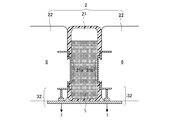
- FIG. 2 is a schematic cross-sectional view schematically showing one aspect of the biological sample holding unit 2 in the biological sample impedance measuring apparatus 1 according to the present technology.
- the biological sample holder 2 illustrated in FIG. 2 includes a container 21 and a container holder 22.
- the container holding unit 22 is designed so that a known cartridge type measurement container can be used as the container 21, only the container holding unit 22 is used. It is also possible to function as the biological sample holder 2. That is, when the biological sample holding unit 2 in the biological sample impedance measuring apparatus 1 according to the present technology is configured by only the container 21, when configured by the container 21 and the container holding unit 22, the biological sample holding unit 2 is configured by only the container holding unit 22. Any of which is included.
- (A) Container 21 In the biological sample impedance measuring apparatus 1 according to the present technology, when the container 21 is used as the biological sample holding unit 2, the specific form thereof is not particularly limited, and the cylindrical can be used as long as the biological sample S to be measured can be held.
- the material constituting the container 21 is not particularly limited, and can be freely selected within a range that does not affect the state and type of the biological sample S to be measured, the measurement purpose, and the like.
- the type of resin that can be used is not particularly limited, and one or more resins that can be used for holding the biological sample S can be freely selected and used.
- hydrophobic and insulating polymers and copolymers such as polypropylene, polymethyl methacrylate, polystyrene, acrylic, polysulfone, polytetrafluoroethylene, and blend polymers may be used.
- the biological sample holding unit 2 with at least one resin selected from polypropylene, polystyrene, acrylic, and polysulfone. Since these resins have a property of low coagulation activity with respect to blood, they can be suitably used for measurement of biological samples containing blood, for example.
- the specific form is not particularly limited, and the container 21 in which the biological sample S to be measured is accommodated. Can be designed freely if it can be held.
- the material constituting the container holding unit 22 is not particularly limited, and can be freely selected according to the form of the container 21 to be held.
- the application unit 3 is a part that applies an alternating voltage to the pair of electrodes 31 a and 31 b that are in contact with the biological sample S held by the biological sample holding unit 2.
- the application unit 3 applies a voltage to the pair of electrodes 31a and 31b, starting from the time when a command to start measurement is received or when the power source of the biological sample impedance measuring apparatus 1 is turned on. More specifically, the application unit 3 sets the frequency set for the electrodes 31a and 31b or the measurement condition described later for each of the set measurement intervals or the measurement intervals controlled by the measurement condition control unit 5 described later. An AC voltage having a frequency controlled by the control unit 5 is applied.
- the application unit 3 can also apply an alternating voltage to a plurality of pairs of electrodes.
- a method of applying an alternating voltage to a plurality of pairs of electrodes for example, a method of simultaneously applying an alternating voltage to a plurality of pairs of electrodes by providing a plurality of applying units 3, and a plurality of methods by scanning one applying unit 3.
- a method of selecting one or a plurality of application units 3 for applying the voltage to the application unit can be used.
- Electrodes 31a and 31b are used to contact the biological sample S during measurement and apply a necessary voltage to the biological sample S.
- the number of the electrode portions 31a and 31b is not particularly limited as long as the impedance of the biological sample S can be measured, and a pair of electrodes are freely arranged. be able to.
- the arrangement and form of the electrodes 31a and 31b are not particularly limited, and can be freely designed according to the form of the biological sample holding unit 2 and the like as long as a necessary voltage can be applied to the biological sample S. it can.
- the electrodes 31 a and 31 b can be integrally formed with the biological sample holder 2 (container 21). , 31b and sealing with the lid, the electrode 31a, 31b can be brought into contact with the biological sample S accommodated in the container 21.
- it can also be set as the structure which can make electrode 31a, 31b contact the biological sample S by inserting a pair of electrode 31a, 31b in the container 21 from the exterior of the container 21 at the time of a measurement.
- the material constituting the electrodes 31a and 31b is not particularly limited, and one or more known electrically conductive materials can be freely used as long as the state and type of the biological sample S to be measured and the measurement purpose are not affected. Can be selected and used. For example, titanium, aluminum, stainless steel, platinum, gold, copper, graphite and the like can be mentioned. In the present technology, it is particularly preferable to form the electrodes 31a and 31b using an electrically conductive material containing titanium. Titanium has a property of low coagulation activity with respect to blood, and therefore can be suitably used for, for example, measurement of a biological sample containing blood.
- connection part 32 is a part which electrically connects the application part 3 and / or the measurement part 4 and the electrodes 31a and 31b.
- the specific form of the connection part 32 is not specifically limited, If it is possible to electrically connect the application part 3 and / or the measurement part 4 and the electrodes 31a and 31b, it can be designed in a free form. it can.
- One aspect of the connecting portion 32 will be described with reference to FIG.
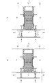
- FIG. 3 is a schematic cross-sectional view schematically showing one aspect of the connection portion 32 in the biological sample impedance measuring apparatus 1 according to the present technology.
- FIG. 3A shows a state during non-measurement
- FIG. 3B shows a state during measurement.
- the connection unit 32 illustrated in FIG. 3 disconnects the application unit 3 and / or the measurement unit 4 and the electrodes 31a and 31b when not measuring, and applies the application unit 3 and / or the measurement unit 4 and the electrode 31a during measurement.
- 31b can be electrically connected to each other.
- the container 21 and the connection part 32 on the container 21 side, or the connection part 32 on the application part 3 and / or measurement part 4 side, or all of these are configured to be drivable.
- the connection part 32 on the container 21 side and the application part 3 and / or the connection part 32 on the measurement part 4 side are brought into a non-contact state, and in the measurement, the connection part 32 on the container 21 side and the application part 3 and By moving the connection part 32 on the measurement part 4 side so as to be in a contact state, the application part 3 and / or the measurement part 4 and the electrodes 31a and 31b can be electrically connected only at the time of measurement. .
- the measuring unit 4 is a part that measures the impedance of the biological sample S obtained by applying an alternating voltage to the biological sample S by the applying unit 3. Specifically, the impedance of the biological sample S between the electrodes 31a and 31b is measured from the time when the instruction to start the measurement is received or the time when the power of the biological sample impedance measuring apparatus 1 is turned on.
- the dielectric constant can be derived from the measured impedance.
- a known function or a relational expression indicating the relationship between the impedance and the dielectric constant can be used.
- the frequency band for measuring impedance in the measurement unit 4 can be appropriately selected according to the type, state, measurement purpose, etc. of the biological sample to be measured. For example, when the biological sample is blood, a change is observed in the impedance in the frequency band shown in Table 1 below according to the change in the state of the blood.
- coagulation for the purpose of predicting or detecting blood coagulation (coagulation), it is preferable to measure impedance at a frequency of 1 kHz to 50 MHz, and more preferably to measure impedance at a frequency of 3 MHz to 15 MHz.
- a preferable frequency band as shown in Table 1 can be automatically selected.
- the measurement unit 4 can also perform a plurality of measurements.
- a method of performing a plurality of measurements for example, a method of performing a plurality of measurements simultaneously by providing a plurality of measurement units 4, a method of performing a plurality of measurements by scanning one measurement unit 4, and the biological sample holding unit 2 And a method of performing a plurality of measurements by moving the measurement unit, a method of selecting one or a plurality of measurement units 4 provided with a plurality of measurement units 4 and actually performing the measurement by switching, and the like.
- the measurement condition control unit 5 is a part that controls the measurement time and / or the measurement frequency in the measurement unit 4.
- the measurement interval is controlled according to the amount of data required for the target analysis, etc., or when the measurement value is almost flat, etc. Timing control can be performed.
- control the measurement frequency includes a method of changing the frequency of the AC voltage applied between the electrodes 31a and 31b or superimposing a plurality of frequencies to measure impedance at a plurality of frequencies.
- Specific methods include a method of arranging a plurality of single frequency analyzers, a method of sweeping frequencies, a method of superimposing frequencies and extracting information of each frequency with a filter, a method of measuring by response to an impulse, and the like. It is done.
- Temperature controller 6 is a part that controls the temperature in the biological sample holding unit 2.
- the temperature control unit 6 is not an essential part, but is preferably provided to keep the biological sample S to be measured in an optimal state for measurement.
- the temperature control unit 6 can also control the temperature in the sample standby unit 12. Further, when a drug is put into the biological sample S at the time of measurement or before the measurement, a temperature control unit 6 may be provided to control the temperature of the drug. In this case, the temperature control unit 6 can be provided for temperature control in the biological sample holding unit 2, temperature control in the sample standby unit 12, and drug temperature control, respectively. Temperature control may be performed.
- the specific method of temperature control is not specifically limited, For example, by making the container holding part 22 shown in FIG. 2 and FIG. 3 have a temperature adjustment function, the container holding part 22 functions as the temperature control part 6. Can do.
- the biological sample supply unit 7 is a part that automatically supplies the biological sample S to the biological sample holding unit 2.
- the biological sample supply unit 7 is not an essential part, but is preferably provided in order to perform each process automatically.
- the specific supply method of the biological sample S is not particularly limited.
- the biological sample S when the biological sample S is in a liquid state, the biological sample S is automatically attached to the biological sample holding unit 2 using a pipettor and a tip attached to the tip of the pipetter. Can be supplied automatically.
- the chip is disposable in order to prevent measurement errors and the like.
- the biological sample S can be automatically supplied from the storage of the biological sample S to the biological sample holding unit 2 using a pump or the like.
- the biological sample S can be automatically supplied to the biological sample holding unit 2 using a permanent nozzle or the like. In this case, it is preferable to provide the nozzle with a cleaning function in order to prevent measurement errors and the like.
- Drug supply unit 8 is a part that automatically supplies one or more drugs to the biological sample holding unit 2.
- the drug supply unit 8 is not an essential part, but is preferably provided in order to perform each process automatically.
- the specific method for supplying the drug is not particularly limited, and can be performed using the same method as that for the biological sample supply unit 7.
- the supply of the drug is preferably a method that can supply a fixed amount of the drug without contacting the biological sample holder 2 (container 21).
- supply by ejection can be performed.
- the biological sample is retained by introducing a chemical solution into the discharge pipe in advance and blowing separately connected pressurized air into the pipe line through the pipe line connected thereto.
- the chemical liquid can be discharged and supplied to the section 2 (container 21). At this time, it is possible to adjust the discharge amount of the chemical liquid by adjusting the air pressure and the valve opening / closing time.
- the chemical solution can be discharged and supplied to the biological sample holding unit 2 (container 21) by utilizing the vaporization of the chemical solution itself or air dissolved therein by heating.
- the generated bubble volume can be adjusted and the discharge amount of the chemical solution can be adjusted.
- the biological sample holding unit 2 is driven by driving a movable part provided in the pipe line using a piezoelectric element (piezo element) or the like without using air, and sending out an amount of drug solution determined by the volume of the movable part.
- the chemical solution can also be supplied to (container 21).
- a medicine by using a so-called ink jet method in which a drug solution is atomized and sprayed directly onto a predetermined biological sample holding unit 2 (container 21).
- the drug supply unit 8 may be provided with an agitation function, a temperature control function, an identification function (for example, a barcode reader) for identifying the type of drug, and the like.
- medical agent can also be previously solidified in the container 21, or can be accommodated with a liquid.
- an anticoagulant, a coagulation initiator, and the like can be placed in the container 21 in advance.
- the medicine supply section 8 and the medicine holding section are not required, and the apparatus can be downsized and the cost can be reduced.
- the user since the user does not need to replace the medicine and the apparatus maintenance of the medicine supply unit 8 and the medicine holding unit is also unnecessary, the usability can be improved.
- the biological sample S that can be measured by the present technology is not particularly limited and can be freely selected.
- the impedance of a liquid or gel biological sample can be preferably measured.
- Specific examples of the liquid biological sample S can include whole blood, plasma, or biological samples S containing blood components such as diluted solutions and / or drug additives.
- Blood state analysis unit 9 is a part that analyzes the change in the state of blood from the temporal change in impedance measured by the measurement unit 4.
- the blood state analysis unit 9 is not an essential part, but when a biological sample containing a blood component is used as the biological sample S, the blood state analysis unit 9 is used. By providing, it is possible to detect a change in the state of blood.
- a parameter indicating each characteristic is extracted from a plurality of impedance measurement values received during the analysis period, and based on a comparison between this parameter and a reference value that defines a reference for blood state change.
- the blood state change can be analyzed.
- a specific example of the change in blood state that can be analyzed is not particularly limited as long as it is a phenomenon in which a temporal change in impedance is observed due to the state change, and various state changes are detected. And can be analyzed.
- blood coagulation clotting
- fibrin formation fibrin clot formation
- clot formation platelet aggregation
- red blood cell formation red blood cell sedimentation (red sedimentation)
- hemolysis such as clot contraction, fibrinolysis, Fibrinorigis etc.
- the accuracy management unit 10 is a part that manages the accuracy of the measurement unit 4. In the biological sample impedance measuring apparatus 1 according to the present technology, the accuracy management unit 10 is not an essential part, but by providing the accuracy management unit 10, the measurement accuracy in the measurement unit 4 can be improved.
- the specific accuracy management method of the measurement unit 4 performed in the accuracy management unit 10 is not particularly limited, and a known accuracy management method can be freely selected and used.
- a method of calibrating the measuring unit 4 by setting a short metal plate or the like in the apparatus 1 and shorting the electrode and the metal plate before starting measurement, a calibration jig, etc. A method of bringing the electrodes into contact with each other, a metal plate or the like is placed in a container having the same form as the container 21 in which the biological sample is placed, and the measurement unit 4 is calibrated by short-circuiting the electrode and the metal plate before starting the measurement.
- the drive mechanism 11 is used to move the biological sample holding unit 2 according to various purposes. For example, when using a biological sample S containing a sediment component as a measurement target, by moving the biological sample holding unit 2 in a direction that changes the direction of gravity applied to the biological sample S held by the biological sample holding unit 2, It is possible to prevent the measurement value from being affected by the sedimentation of the sediment component.
- the application unit 3 and the electrodes 31a and 31b are disconnected from each other at the time of non-measurement, and the application unit 3 and the electrodes 31a and 31b are connected at the time of measurement.
- the biological sample holder 2 can also be driven so that it can be electrically connected.
- the biological sample holding unit 2 is necessary if the biological sample holding unit 2 is configured to be movable as in the example shown in FIG. It is possible to perform measurement, biological sample supply, drug supply, and the like by moving to an appropriate site. That is, since there is no need to move the measurement unit 4, the biological sample supply unit 7, the drug supply unit 8 and the like to the target biological sample holding unit 2, there is no need to provide a drive unit for moving each unit. Miniaturization and cost reduction are possible.
- sample standby unit 12 The sample standby unit 12 is a part for waiting the collected biological sample S before measurement.
- the sample standby unit 12 is not an essential part, but can be provided for smooth measurement.
- the sample standby unit 12 includes an agitation function, a temperature control function, a moving mechanism to the biological sample holding unit 2, an identification function for identifying the type of the biological sample S (for example, a barcode reader), an automatic opening It is also possible to provide functions and the like.
- the stirring mechanism 13 is a mechanism that performs stirring inside the biological sample holding unit 2. More specifically, this is a mechanism for stirring the biological sample S itself held in the biological sample holding unit 2 and stirring the biological sample S and a drug such as a reagent.
- the stirring mechanism 13 is not an essential part. For example, when the biological sample S contains a sedimenting component or when a drug such as a reagent is added during measurement. For example, it is preferable to provide the above. More specifically, for example, when blood is used as the biological sample S, the blood is agitated by the agitating mechanism 13 to prevent red blood cell sedimentation (blood sedimentation).
- the specific stirring method in the stirring mechanism 13 is not particularly limited as long as the effects of the present invention are not impaired, and a known stirring method can be freely selected and used. For example, stirring by pipetting, stirring using a stirring rod or a stirring bar, stirring by reversing the container containing the biological sample S or the medicine upside down, and the like can be given.
- FIG. 5 is a conceptual diagram showing an example of a stirring method when the biological sample S and the reagent R are stirred by pipetting using the stirring mechanism 13.
- a biological sample S for measurement is injected into the biological sample holding unit 2 in which the reagent R is held in advance.
- the reagent R to the biological sample holding unit 2 can be automatically injected into the biological sample holding unit 2 in advance by the medicine supply unit 8 described above, or a cartridge in which the reagent R is held in advance is used as the biological sample holding unit. 2 can also be used.
- the injection of the biological sample S into the biological sample holding unit 2 can be automatically performed by, for example, the biological sample supply unit 7 described above.
- the biological sample S is discharged from the bottom of the biological sample holding unit 2, but the discharge position is not limited to this, and the parameters are set in advance according to the type and state of the biological sample S. It is also possible to perform automatic control of the discharge position.
- Step 2 the biological sample S and / or reagent R is aspirated from a predetermined position of the biological sample holding unit 2.
- suction is performed at the bottom of the biological sample holding unit 2, but the suction position is not limited to this, and parameters are set in advance according to the type and state of the biological sample S. It is also possible to automatically control the suction position.
- the pipette used for pipetting in step 2 and step 3 described later may be the pipette used for injecting the biological sample S in step 1 as it is, or another pipette may be used.
- step 3 the biological sample S and / or reagent R sucked in step 2 is discharged from a predetermined position of the biological sample holding unit 2.
- the ejection is performed at the central portion of the biological sample holding unit 2, but the ejection position is not limited to this, and parameters are set in advance according to the type and state of the biological sample S. It is also possible to automatically control the discharge position.
- Step 1 and Step 3 are set as one set, and the biological sample S and the reagent R can be stirred by repeating pipetting as many times as necessary.
- the biological sample S and the reagent R are agitated by repeating three sets of Step 2 and Step 3, but the number of pipetting is not limited to this, and the biological sample S and the reagent R are not limited to this. It is also possible to set parameters in advance according to the type, state, amount, etc., and to automatically control the number of times stirring is possible.
- FIG. 6 is a schematic conceptual diagram schematically showing the concept of the biological sample impedance measuring system 100 according to the present technology.
- the biological sample impedance measurement system 100 according to the present technology is roughly divided into a biological sample holding unit 2, an application unit 3, a measurement unit 4, a measurement condition control unit 5, a display unit 101, a user interface 102, At least.
- storage part 103, etc. can also be provided as needed.
- each part will be described in detail.
- the biological sample holding unit 2 the application unit 3, the measurement unit 4, the measurement condition control unit 5, the temperature control unit 6, the biological sample supply unit 7, the drug supply unit 8, the blood state analysis unit 9, the accuracy management unit 10, and the drive Since the mechanism 11 is the same as the above-described biological sample impedance measuring apparatus 1, description thereof is omitted here.
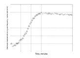
- the display unit 101 is a part that displays data of impedance measured by the measurement unit 4.
- the display unit 101 can display the numerical value data of the impedance measured by the measurement unit 4 as it is, but it can also be displayed as a graph, for example.
- FIG. 7 shows an example of data displayed on the display unit 101.
- the user interface 102 is a part for a user to operate. The user can access each part of the biological sample impedance measuring apparatus 1 according to the present technology through the user interface 102.
- Storage unit 103 is a part that stores data of impedance measured by the measurement unit 4.
- the impedance data measured in the measurement unit 4 can be stored as it is, but the physical property of the biological sample S is analyzed and analyzed using the impedance data measured in the measurement unit 4. It is also possible to store data.
- the biological sample impedance measuring apparatus 1 the display unit 101, the user interface 102, and the storage unit 103 are respectively connected via a network. It may be connected.
- this technique can also take the following structures.
- An application unit for applying an alternating voltage to a pair of electrodes in contact with the biological sample held in the biological sample holding unit;
- a measuring unit for measuring the impedance of the biological sample obtained by applying an alternating voltage to the biological sample by the applying unit;
- a measurement condition control unit for controlling measurement time and / or measurement frequency in the measurement unit;
- An impedance measurement device for biological samples comprising: (2) The biological sample impedance measuring apparatus according to (1), wherein in the measurement time control in the measurement condition control unit, a measurement interval in the measurement unit is controlled.
- the biological sample impedance measuring device according to (1) or (2), wherein in the measurement time control in the measurement condition control unit, the measurement end timing in the measurement unit is controlled.
- the impedance measurement device for a biological sample according to any one of (1) to (3) further including a temperature control unit that controls a temperature in the biological sample holding unit.
- the biological sample impedance measuring device according to any one of (1) to (4), wherein the biological sample holding unit holds the biological sample by holding a container in which the biological sample is stored.
- one or a plurality of biological sample holding units for holding the biological sample;
- An application unit for applying an alternating voltage to a pair of electrodes in contact with the biological sample held in the biological sample holding unit;
- a measuring unit for measuring the impedance of the biological sample obtained by applying an alternating voltage to the biological sample by the applying unit;
- a measurement condition control unit for controlling measurement time and / or measurement frequency in the measurement unit;
- a display unit for displaying impedance data measured in the measurement unit;
- a user interface for user operation, An impedance measurement system for a biological sample.
- the impedance measurement device and system for biological samples according to the present technology can automatically control the measurement time and / or the measurement frequency, depending on the type of biological sample, the purpose of analysis, and the like in impedance measurement of the biological sample It is possible to improve the measurement accuracy promptly.
- 1 Biological sample impedance measuring device
- 2 Biological sample holding unit
- 21 Container
- 22 Container holding unit
- 3 Application unit
- 31a, 31b Electrode
- 32 Connection unit
- 4 Measuring unit
- 5 Measurement Condition control unit
- 6 temperature control unit
- 7 biological sample supply unit
- 8 drug supply unit
- 9 blood state analysis unit
- 10 accuracy management unit
- 11 drive mechanism
- 12 sample standby unit
- 13 agitation Mechanism: 100: Impedance measurement system for biological sample
- 101 Display unit
- 102 User interface
- 103 Storage unit
- R Reagent
- S Biological sample
Landscapes
- Health & Medical Sciences (AREA)
- Life Sciences & Earth Sciences (AREA)
- Engineering & Computer Science (AREA)
- Biomedical Technology (AREA)
- Chemical & Material Sciences (AREA)
- Physics & Mathematics (AREA)
- Hematology (AREA)
- Pathology (AREA)
- Analytical Chemistry (AREA)
- Immunology (AREA)
- General Physics & Mathematics (AREA)
- General Health & Medical Sciences (AREA)
- Biochemistry (AREA)
- Medicinal Chemistry (AREA)
- Molecular Biology (AREA)
- Food Science & Technology (AREA)
- Biophysics (AREA)
- Urology & Nephrology (AREA)
- Ecology (AREA)
- Chemical Kinetics & Catalysis (AREA)
- Electrochemistry (AREA)
- Investigating Or Analyzing Materials By The Use Of Electric Means (AREA)
- Investigating Or Analysing Biological Materials (AREA)
- Measurement And Recording Of Electrical Phenomena And Electrical Characteristics Of The Living Body (AREA)
Priority Applications (5)
| Application Number | Priority Date | Filing Date | Title |
|---|---|---|---|
| EP13873052.8A EP2950087B1 (en) | 2013-01-28 | 2013-12-26 | Impedance measuring device for biological samples and impedance measuring system for biological samples |
| JP2014558477A JP6409574B2 (ja) | 2013-01-28 | 2013-12-26 | 生体試料用インピーダンス測定装置および生体試料用インピーダンス測定システム |
| CN201380071071.4A CN104937400B (zh) | 2013-01-28 | 2013-12-26 | 用于生物样品的阻抗测量装置和用于生物样品的阻抗测量系统 |
| US14/761,667 US9952168B2 (en) | 2013-01-28 | 2013-12-26 | Impedance measuring device for biological samples and impedance measuring system for biological samples |
| US15/920,911 US10801980B2 (en) | 2013-01-28 | 2018-03-14 | Impedance measuring device for biological samples and impedance measuring system for biological samples |
Applications Claiming Priority (2)
| Application Number | Priority Date | Filing Date | Title |
|---|---|---|---|
| JP2013013134 | 2013-01-28 | ||
| JP2013-013134 | 2013-01-28 |
Related Child Applications (2)
| Application Number | Title | Priority Date | Filing Date |
|---|---|---|---|
| US14/761,667 A-371-Of-International US9952168B2 (en) | 2013-01-28 | 2013-12-26 | Impedance measuring device for biological samples and impedance measuring system for biological samples |
| US15/920,911 Continuation US10801980B2 (en) | 2013-01-28 | 2018-03-14 | Impedance measuring device for biological samples and impedance measuring system for biological samples |
Publications (1)
| Publication Number | Publication Date |
|---|---|
| WO2014115478A1 true WO2014115478A1 (ja) | 2014-07-31 |
Family
ID=51227278
Family Applications (1)
| Application Number | Title | Priority Date | Filing Date |
|---|---|---|---|
| PCT/JP2013/084887 WO2014115478A1 (ja) | 2013-01-28 | 2013-12-26 | 生体試料用インピーダンス測定装置および生体試料用インピーダンス測定システム |
Country Status (5)
| Country | Link |
|---|---|
| US (2) | US9952168B2 (zh) |
| EP (1) | EP2950087B1 (zh) |
| JP (3) | JP6409574B2 (zh) |
| CN (2) | CN108931632A (zh) |
| WO (1) | WO2014115478A1 (zh) |
Cited By (17)
| Publication number | Priority date | Publication date | Assignee | Title |
|---|---|---|---|---|
| JP2016029364A (ja) * | 2014-07-24 | 2016-03-03 | ソニー株式会社 | コンタクト構造体、及び該コンタクト構造体を用いた生体試料用電気的測定装置 |
| EP3001196A3 (en) * | 2014-09-29 | 2016-06-29 | C A Casyso AG | Blood testing system and method |
| WO2016113984A1 (ja) * | 2015-01-16 | 2016-07-21 | ソニー株式会社 | 電気的測定用カートリッジ、生体試料用電気的測定装置及び生体試料用電気的測定方法 |
| WO2016132779A1 (ja) * | 2015-02-20 | 2016-08-25 | ソニー株式会社 | 電気的特性測定装置、電気的特性測定システム、電気的特性測定方法、及び該方法をコンピューターに実現させるための電気的特性測定用プログラム |
| WO2016158148A1 (ja) * | 2015-03-31 | 2016-10-06 | ソニー株式会社 | 電気的測定方法、電気的測定装置、及び血液状態解析システム |
| US9739789B2 (en) | 2008-12-23 | 2017-08-22 | C A Casyso Ag | Cartridge device for a measuring system for measuring viscoelastic characteristics of a sample liquid, a corresponding measuring system, and a corresponding method |
| US9897618B2 (en) | 2014-09-29 | 2018-02-20 | C A Casyso Gmbh | Blood testing system |
| JP2018059799A (ja) * | 2016-10-05 | 2018-04-12 | ソニー株式会社 | 血小板凝集能解析方法、血小板凝集能解析装置、血小板凝集能解析用プログラム及び血小板凝集能解析システム |
| US10288630B2 (en) | 2014-09-29 | 2019-05-14 | C A Casyso Gmbh | Blood testing system and method |
| US10295554B2 (en) | 2015-06-29 | 2019-05-21 | C A Casyso Gmbh | Blood testing system and method |
| US10473674B2 (en) | 2016-08-31 | 2019-11-12 | C A Casyso Gmbh | Controlled blood delivery to mixing chamber of a blood testing cartridge |
| US10539579B2 (en) | 2014-09-29 | 2020-01-21 | C A Casyso Gmbh | Blood testing system and method |
| US10816559B2 (en) | 2014-09-29 | 2020-10-27 | Ca Casyso Ag | Blood testing system and method |
| US10843185B2 (en) | 2017-07-12 | 2020-11-24 | Ca Casyso Gmbh | Autoplatelet cartridge device |
| JP2020190570A (ja) * | 2016-10-05 | 2020-11-26 | ソニー株式会社 | 血小板凝集能解析方法、血小板凝集能解析装置、血小板凝集能解析用プログラム及び血小板凝集能解析システム |
| JP2021036246A (ja) * | 2016-02-17 | 2021-03-04 | ソニー株式会社 | 血小板凝集能解析装置、血小板凝集能解析システム、血小板凝集能解析用プログラム及び血小板凝集能の解析方法 |
| CN117214536A (zh) * | 2023-09-06 | 2023-12-12 | 河南工业大学 | 一种适用于高温条件的多路并行阻抗的测试装置及测试方法 |
Families Citing this family (7)
| Publication number | Priority date | Publication date | Assignee | Title |
|---|---|---|---|---|
| CN108931632A (zh) | 2013-01-28 | 2018-12-04 | 索尼公司 | 电测量容器、阻抗测量装置及其操作方法 |
| EP2975387B1 (en) | 2013-03-13 | 2021-03-31 | Sony Corporation | Device for analyzing condition of blood, system for analyzing condition of blood, and program for analyzing condition of blood |
| US10648936B2 (en) | 2013-03-15 | 2020-05-12 | Sony Corporation | Blood condition analyzing device, blood condition analyzing system, blood conditon analyzing method, and blood condition analyzing program for causing computer to execute the method |
| JPWO2014156370A1 (ja) | 2013-03-29 | 2017-02-16 | ソニー株式会社 | 血液状態評価装置、血液状態評価システム、血液状態評価方法及びプログラム |
| WO2014156371A1 (ja) | 2013-03-29 | 2014-10-02 | ソニー株式会社 | 血液状態解析装置、血液状態解析システム、血液状態解析方法及びプログラム |
| CN107890577B (zh) * | 2017-10-23 | 2021-04-06 | 南方科技大学 | 一种灭菌机器人系统 |
| RU2722573C1 (ru) * | 2019-07-31 | 2020-06-01 | Александр Григорьевич Тоневицкий | Устройство для измерения спектра импеданса биологических структур |
Citations (7)
| Publication number | Priority date | Publication date | Assignee | Title |
|---|---|---|---|---|
| JPH0560749A (ja) * | 1990-09-14 | 1993-03-12 | Sankyo Co Ltd | 血液凝固時間測定装置 |
| JP2003526108A (ja) * | 2000-03-09 | 2003-09-02 | クリニカル アナリシス コーポレーション | 医学的診断システム |
| JP2009042141A (ja) | 2007-08-10 | 2009-02-26 | Sony Corp | 細胞の物性値測定方法及び物性測定装置 |
| JP2010181400A (ja) | 2009-01-08 | 2010-08-19 | Sony Corp | 血液凝固系解析装置、血液凝固系解析方法及びプログラム |
| JP2011013005A (ja) * | 2009-06-30 | 2011-01-20 | Beckman Coulter Inc | 液面検知機構、自動分析装置、および液面検知方法 |
| JP2011039070A (ja) * | 2003-09-10 | 2011-02-24 | Abbott Point Of Care Inc | 免疫参照電極を有する免疫測定装置 |
| JP2011112497A (ja) | 2009-11-26 | 2011-06-09 | Sony Corp | 血球細胞分析装置、血球細胞分析方法及び血球細胞分析システム |
Family Cites Families (29)
| Publication number | Priority date | Publication date | Assignee | Title |
|---|---|---|---|---|
| NL298730A (zh) * | 1962-04-18 | |||
| JPH0743404B2 (ja) * | 1987-01-05 | 1995-05-15 | 潔 永田 | 液体の電気抵抗を直読可能にしたテスター用アタッチメント |
| US6201400B1 (en) | 1998-06-23 | 2001-03-13 | The Boeing Company | Bulls-eye mid-frequency impedance probe |
| EP1406537B1 (en) * | 2001-06-12 | 2011-01-12 | Pelikan Technologies Inc. | Integrated blood sampling analysis system with multi-use sampling module |
| US7892185B2 (en) * | 2002-04-19 | 2011-02-22 | Pelikan Technologies, Inc. | Method and apparatus for body fluid sampling and analyte sensing |
| US7569393B2 (en) | 2002-06-28 | 2009-08-04 | International Technidyne Corporation | Analytical test cartridge; and, methods |
| EP2711415B1 (en) * | 2002-12-26 | 2022-02-16 | Meso Scale Technologies, LLC. | Assay cartridges and methods of using the same |
| EP1813937A1 (de) * | 2006-01-25 | 2007-08-01 | Roche Diagnostics GmbH | Elektrochemisches Biosensor-Analysesystem |
| JP4871618B2 (ja) * | 2006-03-14 | 2012-02-08 | 株式会社日立ハイテクノロジーズ | 精度管理システム |
| JP4925703B2 (ja) * | 2006-03-30 | 2012-05-09 | シスメックス株式会社 | 血液凝固分析装置 |
| CN101135662B (zh) * | 2006-08-30 | 2010-11-10 | 梅特勒-托利多仪器(上海)有限公司 | 电位分析电极测量的方法及装置 |
| US8158374B1 (en) * | 2006-09-05 | 2012-04-17 | Ridge Diagnostics, Inc. | Quantitative diagnostic methods using multiple parameters |
| CN101038284B (zh) * | 2007-04-25 | 2011-04-27 | 博奥生物有限公司 | 一种提高电阻抗检测装置的电阻抗检测灵敏度的方法 |
| US8259299B2 (en) * | 2007-06-21 | 2012-09-04 | Rf Science & Technology Inc. | Gas scanning and analysis |
| JP2009244197A (ja) * | 2008-03-31 | 2009-10-22 | Hioki Ee Corp | 薬剤感受性試験方法及び装置 |
| JP5098817B2 (ja) | 2008-05-29 | 2012-12-12 | ソニー株式会社 | 物性測定装置及び物性測定方法 |
| US9307935B2 (en) * | 2008-10-27 | 2016-04-12 | Biosensors, Inc. | Non-invasive monitoring of blood metabolite levels |
| GB2479687B (en) * | 2009-02-10 | 2013-11-20 | Panasonic Corp | Device and method for measuring microspheres |
| PL2461395T3 (pl) * | 2009-06-30 | 2019-05-31 | Lg Chemical Ltd | Sposób wytwarzania elektrody z porowatą warstwą powlekającą |
| JP5499379B2 (ja) | 2009-08-28 | 2014-05-21 | 独立行政法人国立高等専門学校機構 | 液体の誘電率測定装置及び測定方法 |
| JP5768422B2 (ja) * | 2011-03-17 | 2015-08-26 | ソニー株式会社 | 血液凝固系解析方法および血液凝固系解析装置 |
| CN102590637B (zh) * | 2012-03-19 | 2014-03-12 | 厦门大学 | 微波介质涂层电控检测装置及其检测方法 |
| CN108931632A (zh) * | 2013-01-28 | 2018-12-04 | 索尼公司 | 电测量容器、阻抗测量装置及其操作方法 |
| WO2014122873A1 (ja) | 2013-02-08 | 2014-08-14 | ソニー株式会社 | 微小粒子分析装置及び微小粒子分析システム |
| EP2975387B1 (en) | 2013-03-13 | 2021-03-31 | Sony Corporation | Device for analyzing condition of blood, system for analyzing condition of blood, and program for analyzing condition of blood |
| US10648936B2 (en) | 2013-03-15 | 2020-05-12 | Sony Corporation | Blood condition analyzing device, blood condition analyzing system, blood conditon analyzing method, and blood condition analyzing program for causing computer to execute the method |
| US20160025610A1 (en) | 2013-03-26 | 2016-01-28 | Sony Corporation | Measurement apparatus and measurement method |
| JPWO2014156370A1 (ja) | 2013-03-29 | 2017-02-16 | ソニー株式会社 | 血液状態評価装置、血液状態評価システム、血液状態評価方法及びプログラム |
| WO2014156371A1 (ja) | 2013-03-29 | 2014-10-02 | ソニー株式会社 | 血液状態解析装置、血液状態解析システム、血液状態解析方法及びプログラム |
-
2013
- 2013-12-26 CN CN201810540745.5A patent/CN108931632A/zh active Pending
- 2013-12-26 US US14/761,667 patent/US9952168B2/en active Active
- 2013-12-26 CN CN201380071071.4A patent/CN104937400B/zh active Active
- 2013-12-26 WO PCT/JP2013/084887 patent/WO2014115478A1/ja active Application Filing
- 2013-12-26 EP EP13873052.8A patent/EP2950087B1/en active Active
- 2013-12-26 JP JP2014558477A patent/JP6409574B2/ja active Active
-
2018
- 2018-03-14 US US15/920,911 patent/US10801980B2/en active Active
- 2018-09-25 JP JP2018178965A patent/JP2019020423A/ja active Pending
-
2020
- 2020-06-05 JP JP2020098621A patent/JP7006727B2/ja active Active
Patent Citations (7)
| Publication number | Priority date | Publication date | Assignee | Title |
|---|---|---|---|---|
| JPH0560749A (ja) * | 1990-09-14 | 1993-03-12 | Sankyo Co Ltd | 血液凝固時間測定装置 |
| JP2003526108A (ja) * | 2000-03-09 | 2003-09-02 | クリニカル アナリシス コーポレーション | 医学的診断システム |
| JP2011039070A (ja) * | 2003-09-10 | 2011-02-24 | Abbott Point Of Care Inc | 免疫参照電極を有する免疫測定装置 |
| JP2009042141A (ja) | 2007-08-10 | 2009-02-26 | Sony Corp | 細胞の物性値測定方法及び物性測定装置 |
| JP2010181400A (ja) | 2009-01-08 | 2010-08-19 | Sony Corp | 血液凝固系解析装置、血液凝固系解析方法及びプログラム |
| JP2011013005A (ja) * | 2009-06-30 | 2011-01-20 | Beckman Coulter Inc | 液面検知機構、自動分析装置、および液面検知方法 |
| JP2011112497A (ja) | 2009-11-26 | 2011-06-09 | Sony Corp | 血球細胞分析装置、血球細胞分析方法及び血球細胞分析システム |
Non-Patent Citations (2)
| Title |
|---|
| AKIHIKO IRIMAJIRI ET AL.: "Zenketsu no Yuden Kyodo kara Mita Sekkekkyu Gyoshu (Renzen Keisei", JOURNAL OF THE SOCIETY FOR BIOSCIENCE AND BIOENGINEERING, JAPAN, vol. 78, no. 5, 25 May 2000 (2000-05-25), pages 162 - 165, XP008180851 * |
| See also references of EP2950087A4 |
Cited By (40)
| Publication number | Priority date | Publication date | Assignee | Title |
|---|---|---|---|---|
| US10746750B2 (en) | 2008-12-23 | 2020-08-18 | C A Casyso Gmbh | Cartridge device for a measuring system for measuring viscoelastic characteristics of a sample liquid, a corresponding measuring system, and a corresponding method |
| US11892459B2 (en) | 2008-12-23 | 2024-02-06 | C A Casyso Gmbh | Cartridge device for a measuring system for measuring viscoelastic characteristics of a sample liquid, a corresponding measuring system, and a corresponding method |
| US11879899B2 (en) | 2008-12-23 | 2024-01-23 | C A Casyso Gmbh | Cartridge device for a measuring system for measuring viscoelastic characteristics of a sample liquid, a corresponding measuring system, and a corresponding method |
| US11768211B2 (en) | 2008-12-23 | 2023-09-26 | C A Casyso Gmbh | Cartridge device for a measuring system for measuring viscoelastic characteristics of a sample liquid, a corresponding measuring system, and a corresponding method |
| US11360106B2 (en) | 2008-12-23 | 2022-06-14 | C A Casyso Gmbh | Cartridge device for a measuring system for measuring viscoelastic characteristics of a sample liquid, a corresponding measuring system, and a corresponding method |
| US9739789B2 (en) | 2008-12-23 | 2017-08-22 | C A Casyso Ag | Cartridge device for a measuring system for measuring viscoelastic characteristics of a sample liquid, a corresponding measuring system, and a corresponding method |
| US11131680B2 (en) | 2008-12-23 | 2021-09-28 | C A Casyso Gmbh | Cartridge device for a measuring system for measuring viscoelastic characteristics of a sample liquid, a corresponding measuring system, and a corresponding method |
| US11061038B2 (en) | 2008-12-23 | 2021-07-13 | C A Casyso Gmbh | Cartridge device for a measuring system for measuring viscoelastic characteristics of a sample liquid, a corresponding measuring system, and a corresponding method |
| US9915671B2 (en) | 2008-12-23 | 2018-03-13 | C A Casyso Ag | Cartridge device for a measuring system for measuring viscoelastic characteristics of a sample liquid, a corresponding measuring system, and a corresponding method |
| US10996230B2 (en) | 2008-12-23 | 2021-05-04 | C A Casyso Gmbh | Cartridge device for a measuring system for measuring viscoelastic characteristics of a sample liquid, a corresponding measuring system, and a corresponding method |
| JP2016029364A (ja) * | 2014-07-24 | 2016-03-03 | ソニー株式会社 | コンタクト構造体、及び該コンタクト構造体を用いた生体試料用電気的測定装置 |
| US11327069B2 (en) | 2014-09-29 | 2022-05-10 | Ca Casyso Gmbh | Blood testing system and method |
| US10816559B2 (en) | 2014-09-29 | 2020-10-27 | Ca Casyso Ag | Blood testing system and method |
| US10175225B2 (en) | 2014-09-29 | 2019-01-08 | C A Casyso Ag | Blood testing system and method |
| US10288630B2 (en) | 2014-09-29 | 2019-05-14 | C A Casyso Gmbh | Blood testing system and method |
| US9897618B2 (en) | 2014-09-29 | 2018-02-20 | C A Casyso Gmbh | Blood testing system |
| US11719688B2 (en) | 2014-09-29 | 2023-08-08 | C A Casyso Gmbh | Blood testing system and method |
| US10539579B2 (en) | 2014-09-29 | 2020-01-21 | C A Casyso Gmbh | Blood testing system and method |
| EP3001196A3 (en) * | 2014-09-29 | 2016-06-29 | C A Casyso AG | Blood testing system and method |
| WO2016113984A1 (ja) * | 2015-01-16 | 2016-07-21 | ソニー株式会社 | 電気的測定用カートリッジ、生体試料用電気的測定装置及び生体試料用電気的測定方法 |
| CN107209134A (zh) * | 2015-02-20 | 2017-09-26 | 索尼公司 | 电特性测量设备、电特性测量系统、电特性测量方法以及用于使计算机实现所述方法的电特性测量程序 |
| US10571417B2 (en) | 2015-02-20 | 2020-02-25 | Sony Corporation | Electrical characteristic measurement apparatus, electrical characteristic measurement system, electrical characteristic measurement method, and program for electrical characteristic measurement for causing computer to implement the method |
| WO2016132779A1 (ja) * | 2015-02-20 | 2016-08-25 | ソニー株式会社 | 電気的特性測定装置、電気的特性測定システム、電気的特性測定方法、及び該方法をコンピューターに実現させるための電気的特性測定用プログラム |
| CN107209134B (zh) * | 2015-02-20 | 2020-05-26 | 索尼公司 | 电特性测量设备、电特性测量系统、电特性测量方法以及用于使计算机实现所述方法的电特性测量程序 |
| EP3260852A4 (en) * | 2015-02-20 | 2018-11-07 | Sony Corporation | Electrical characteristic measurement device, electrical characteristic measurement system, electrical characteristic measurement method, and electrical characteristic measurement program for causing computer to implement said method |
| JPWO2016132779A1 (ja) * | 2015-02-20 | 2017-11-30 | ソニー株式会社 | 電気的特性測定装置、電気的特性測定システム、電気的特性測定方法、及び該方法をコンピューターに実現させるための電気的特性測定用プログラム |
| US10816493B2 (en) | 2015-03-31 | 2020-10-27 | Sony Corporation | Electrical measurement method, electrical measurement device, and blood condition analysis system |
| WO2016158148A1 (ja) * | 2015-03-31 | 2016-10-06 | ソニー株式会社 | 電気的測定方法、電気的測定装置、及び血液状態解析システム |
| US10295554B2 (en) | 2015-06-29 | 2019-05-21 | C A Casyso Gmbh | Blood testing system and method |
| US11085938B2 (en) | 2015-06-29 | 2021-08-10 | C A Casyso Gmbh | Thromboelastometry blood testing system and accuracy control methods |
| JP2021036246A (ja) * | 2016-02-17 | 2021-03-04 | ソニー株式会社 | 血小板凝集能解析装置、血小板凝集能解析システム、血小板凝集能解析用プログラム及び血小板凝集能の解析方法 |
| JP7070641B2 (ja) | 2016-02-17 | 2022-05-18 | ソニーグループ株式会社 | 血小板凝集能解析装置、血小板凝集能解析システム、血小板凝集能解析用プログラム及び血小板凝集能の解析方法 |
| US10473674B2 (en) | 2016-08-31 | 2019-11-12 | C A Casyso Gmbh | Controlled blood delivery to mixing chamber of a blood testing cartridge |
| JP2018059799A (ja) * | 2016-10-05 | 2018-04-12 | ソニー株式会社 | 血小板凝集能解析方法、血小板凝集能解析装置、血小板凝集能解析用プログラム及び血小板凝集能解析システム |
| JP2020190570A (ja) * | 2016-10-05 | 2020-11-26 | ソニー株式会社 | 血小板凝集能解析方法、血小板凝集能解析装置、血小板凝集能解析用プログラム及び血小板凝集能解析システム |
| US11802825B2 (en) | 2016-10-05 | 2023-10-31 | Sony Corporation | Platelet aggregation analysis method, platelet aggregation analysis device, program for analyzing platelet aggregation, and platelet aggregation analysis system |
| WO2018066207A1 (ja) * | 2016-10-05 | 2018-04-12 | ソニー株式会社 | 血小板凝集能解析方法、血小板凝集能解析装置、血小板凝集能解析用プログラム及び血小板凝集能解析システム |
| US11691142B2 (en) | 2017-07-12 | 2023-07-04 | Ca Casyso Gmbh | Autoplatelet cartridge device |
| US10843185B2 (en) | 2017-07-12 | 2020-11-24 | Ca Casyso Gmbh | Autoplatelet cartridge device |
| CN117214536A (zh) * | 2023-09-06 | 2023-12-12 | 河南工业大学 | 一种适用于高温条件的多路并行阻抗的测试装置及测试方法 |
Also Published As
| Publication number | Publication date |
|---|---|
| JPWO2014115478A1 (ja) | 2017-01-26 |
| US20150323480A1 (en) | 2015-11-12 |
| EP2950087A4 (en) | 2016-09-28 |
| CN108931632A (zh) | 2018-12-04 |
| JP7006727B2 (ja) | 2022-01-24 |
| JP2020165982A (ja) | 2020-10-08 |
| US9952168B2 (en) | 2018-04-24 |
| EP2950087B1 (en) | 2020-11-04 |
| EP2950087A1 (en) | 2015-12-02 |
| JP2019020423A (ja) | 2019-02-07 |
| JP6409574B2 (ja) | 2018-10-24 |
| CN104937400A (zh) | 2015-09-23 |
| US10801980B2 (en) | 2020-10-13 |
| US20180202955A1 (en) | 2018-07-19 |
| CN104937400B (zh) | 2018-07-03 |
Similar Documents
| Publication | Publication Date | Title |
|---|---|---|
| JP7006727B2 (ja) | 生体試料用インピーダンス測定装置および生体試料用インピーダンス測定システム | |
| EP3321669B1 (en) | Device for electrical measurement of target chemical substances, and method therefor | |
| US20070109139A1 (en) | Electrical drop surveillance | |
| US10352954B2 (en) | Sensing tip with electrical impedance sensor | |
| US11899008B2 (en) | Blood state analysis apparatus, blood state analysis system, blood state analysis method, and program | |
| JP2016085103A (ja) | 臨床検査装置 | |
| WO2017168885A1 (ja) | 電気的特性測定装置、電気的特性測定システム、電気的特性測定方法、及びプログラム | |
| JP7135620B2 (ja) | 血液凝固系解析装置、血液凝固系解析方法及び血液凝固系解析プログラム | |
| JP2016029364A (ja) | コンタクト構造体、及び該コンタクト構造体を用いた生体試料用電気的測定装置 | |
| US20210263052A1 (en) | Blood coagulation system analysis device | |
| US10634660B2 (en) | Electrical characteristic measurement device, electrical characteristic measurement method, and blood condition analysis system | |
| JP2016045071A (ja) | 電気的特性測定装置、血液状態解析システム、電気的特性測定方法、及び該方法をコンピューターに実現させるための電気的特性測定用プログラム | |
| JPWO2016132779A1 (ja) | 電気的特性測定装置、電気的特性測定システム、電気的特性測定方法、及び該方法をコンピューターに実現させるための電気的特性測定用プログラム | |
| WO2016013300A1 (ja) | 電気的測定用カートリッジ、生体試料用電気的測定装置、生体試料用電気的測定システム及び生体試料用電気的測定方法 | |
| KR20130016562A (ko) | 혈소판 복합기능 검사 장치 및 방법, 이에 구비되는 미세교반칩 |
Legal Events
| Date | Code | Title | Description |
|---|---|---|---|
| 121 | Ep: the epo has been informed by wipo that ep was designated in this application |
Ref document number: 13873052 Country of ref document: EP Kind code of ref document: A1 |
|
| ENP | Entry into the national phase |
Ref document number: 2014558477 Country of ref document: JP Kind code of ref document: A |
|
| WWE | Wipo information: entry into national phase |
Ref document number: 2013873052 Country of ref document: EP |
|
| WWE | Wipo information: entry into national phase |
Ref document number: 14761667 Country of ref document: US |
|
| NENP | Non-entry into the national phase |
Ref country code: DE |