WO2016113984A1 - 電気的測定用カートリッジ、生体試料用電気的測定装置及び生体試料用電気的測定方法 - Google Patents
電気的測定用カートリッジ、生体試料用電気的測定装置及び生体試料用電気的測定方法 Download PDFInfo
- Publication number
- WO2016113984A1 WO2016113984A1 PCT/JP2015/081103 JP2015081103W WO2016113984A1 WO 2016113984 A1 WO2016113984 A1 WO 2016113984A1 JP 2015081103 W JP2015081103 W JP 2015081103W WO 2016113984 A1 WO2016113984 A1 WO 2016113984A1
- Authority
- WO
- WIPO (PCT)
- Prior art keywords
- biological sample
- electrical measurement
- cartridge
- unit
- electrical
- Prior art date
Links
Images


Classifications
-
- G—PHYSICS
- G01—MEASURING; TESTING
- G01N—INVESTIGATING OR ANALYSING MATERIALS BY DETERMINING THEIR CHEMICAL OR PHYSICAL PROPERTIES
- G01N27/00—Investigating or analysing materials by the use of electric, electrochemical, or magnetic means
- G01N27/02—Investigating or analysing materials by the use of electric, electrochemical, or magnetic means by investigating impedance
- G01N27/04—Investigating or analysing materials by the use of electric, electrochemical, or magnetic means by investigating impedance by investigating resistance
- G01N27/06—Investigating or analysing materials by the use of electric, electrochemical, or magnetic means by investigating impedance by investigating resistance of a liquid
- G01N27/07—Construction of measuring vessels; Electrodes therefor
-
- B—PERFORMING OPERATIONS; TRANSPORTING
- B01—PHYSICAL OR CHEMICAL PROCESSES OR APPARATUS IN GENERAL
- B01L—CHEMICAL OR PHYSICAL LABORATORY APPARATUS FOR GENERAL USE
- B01L3/00—Containers or dishes for laboratory use, e.g. laboratory glassware; Droppers
- B01L3/50—Containers for the purpose of retaining a material to be analysed, e.g. test tubes
-
- G—PHYSICS
- G01—MEASURING; TESTING
- G01N—INVESTIGATING OR ANALYSING MATERIALS BY DETERMINING THEIR CHEMICAL OR PHYSICAL PROPERTIES
- G01N33/00—Investigating or analysing materials by specific methods not covered by groups G01N1/00 - G01N31/00
- G01N33/48—Biological material, e.g. blood, urine; Haemocytometers
- G01N33/50—Chemical analysis of biological material, e.g. blood, urine; Testing involving biospecific ligand binding methods; Immunological testing
- G01N33/86—Chemical analysis of biological material, e.g. blood, urine; Testing involving biospecific ligand binding methods; Immunological testing involving blood coagulating time or factors, or their receptors
-
- B—PERFORMING OPERATIONS; TRANSPORTING
- B01—PHYSICAL OR CHEMICAL PROCESSES OR APPARATUS IN GENERAL
- B01L—CHEMICAL OR PHYSICAL LABORATORY APPARATUS FOR GENERAL USE
- B01L2300/00—Additional constructional details
- B01L2300/06—Auxiliary integrated devices, integrated components
- B01L2300/0627—Sensor or part of a sensor is integrated
- B01L2300/0645—Electrodes
-
- B—PERFORMING OPERATIONS; TRANSPORTING
- B01—PHYSICAL OR CHEMICAL PROCESSES OR APPARATUS IN GENERAL
- B01L—CHEMICAL OR PHYSICAL LABORATORY APPARATUS FOR GENERAL USE
- B01L2300/00—Additional constructional details
- B01L2300/08—Geometry, shape and general structure
- B01L2300/0832—Geometry, shape and general structure cylindrical, tube shaped
-
- B—PERFORMING OPERATIONS; TRANSPORTING
- B01—PHYSICAL OR CHEMICAL PROCESSES OR APPARATUS IN GENERAL
- B01L—CHEMICAL OR PHYSICAL LABORATORY APPARATUS FOR GENERAL USE
- B01L2300/00—Additional constructional details
- B01L2300/08—Geometry, shape and general structure
- B01L2300/0848—Specific forms of parts of containers
- B01L2300/0858—Side walls
Definitions
- This technology relates to an electrical measurement cartridge for measuring electrical characteristics of a biological sample. More specifically, the present invention relates to an electrical measurement cartridge that can reduce the risk of contact with a connecting portion, an electrical measurement device for a biological sample using the electrical measurement cartridge, and an electrical measurement method for a biological sample.
- the measured electrical characteristics include complex dielectric constant and frequency dispersion (dielectric spectrum).
- the complex permittivity and its frequency dispersion are generally calculated by measuring the complex capacitance or complex impedance between the electrodes using a solution holder or the like having an electrode for applying a voltage to the solution.
- Patent Document 2 discloses a technique for acquiring information related to blood coagulation from the dielectric constant of blood. “A pair of electrodes and an alternating voltage with respect to the pair of electrodes at predetermined time intervals”. Applying means for applying, measuring means for measuring the dielectric constant of blood disposed between the pair of electrodes, and blood measured at the time interval after the anticoagulant action acting on the blood is released. A blood coagulation system analyzer having analysis means for analyzing the degree of action of the blood coagulation system using a dielectric constant is described.
- Patent Document 3 discloses a biological sample holding unit made of a resin for containing a liquid biological sample, and an electric conduction unit fixed to the biological sample holding unit. , And an electrical measurement of a liquid biological sample in which the biological sample holding part and the electric conduction part are integrally molded in a state where a part of the electric conduction part is embedded in the biological sample holding part A container is disclosed.
- the container disclosed in Patent Document 3 is not covered with the connection part, which is a part of the electric conduction part, and is in an exposed state. Therefore, when the user performs the electrical property measurement of the biological sample using the container disclosed in Patent Document 3, or when the manufacturing worker manufactures the container disclosed in Patent Document 3, The risk of touching the connection is very high.
- connection part is exposed in the conventional container for electrical measurement of a biological sample, and it is difficult to reduce the risk of contact with the connection part.
- the main object of the present technology is to provide an electrical measurement cartridge that can reduce the risk of contact with the connection portion.
- the inventors of the present invention have conducted intensive research on the structure of the cartridge used when measuring the electrical characteristics.
- the cartridge includes a protective portion that protects the connection portion. We succeeded in reducing the risk of contact with the connecting part, and completed this technology.
- a biological sample holding unit that stores a biological sample; At least a pair of electrodes fixed to the biological sample holder; A connection part for electrically connecting the electrode and an external circuit; A protection part for protecting the connection part;
- An electrical measurement cartridge is provided.
- the electrical measurement cartridge according to the present technology may include a guide unit that is fixed to the biological sample holding unit and guides the insertion of the cartridge into the biological sample electrical measurement device. Furthermore, the guide part can also function as the protection part.
- the electrical measurement cartridge according to the present technology can also enclose a reagent in a part of the biological sample holder.
- the material of the biological sample holding part and / or the protection part is not particularly limited, but a resin can be used.
- the type of the resin is not particularly limited, but one or more resins selected from polypropylene, polystyrene, acrylic, and polysulfone can be used.
- the biological sample may be a blood sample.
- the electrical measurement cartridge according to the present technology can also be used for measuring a blood coagulation state.
- an electrical measurement device for a biological sample that measures electrical characteristics of the biological sample
- a biological sample holding unit for storing the biological sample; at least a pair of electrodes fixed to the biological sample holding unit; a connection unit for electrically connecting the electrode and an external circuit; and a protection unit for protecting the connection unit
- a cartridge insertion part for inserting an electrical measurement cartridge,
- An application unit for applying a voltage to the connection unit;
- An electrical measurement device for biological samples comprising at least Further, the biological sample electrical measurement device according to the present technology is such that the electrical measurement cartridge is fixed to the biological sample holding unit and guides the insertion of the cartridge into the biological sample electrical measurement device.
- the cartridge insertion portion may include a guided portion with which the guide portion is engaged.
- a biological sample holding unit that stores the biological sample; At least a pair of electrodes fixed to the biological sample holder; A connection part for electrically connecting the electrode and an external circuit; A protection part for protecting the connection part; There is also provided an electrical measurement method for a biological sample for measuring electrical characteristics of the biological sample using an electrical measurement cartridge comprising at least the above.
- the cartridge for electrical measurement according to the present technology includes a protective part that protects the connection part, and thus can reduce the risk of contact with the connection part.
- the effect described here is not necessarily limited, and may be any effect described in the present technology.
- A is a schematic end view when viewed from the direction of arrow a in FIG. 1
- B is a schematic end view when viewed from the direction of arrow b in FIG.
- It is an end surface mimetic diagram showing typically a 2nd embodiment of cartridge 1 for electrical measurement concerning this art.
- It is an end surface mimetic diagram showing typically a 3rd embodiment of cartridge 1 for electrical measurement concerning this art.
- It is an end surface mimetic diagram showing typically a 4th embodiment of cartridge 1 for electric measurement concerning this art.
- 1 is a schematic conceptual diagram schematically showing a first embodiment of a biological sample electrical measurement apparatus 10 according to the present technology.
- It is a schematic conceptual diagram which shows typically 2nd Embodiment of the electrical measurement apparatus 10 for biological samples which concerns on this technique.
- It is a mimetic diagram showing typically a 1st embodiment of kit K for electrical measurement for biological samples concerning this art.
- Electrical measurement cartridge 1 (1) Biological sample holder 11 (2) Electrode 12 (3) Connection unit 13 (4) Protection unit 14 (5) Guide portion 15 (6) Sealing portion 16 (7) Biological sample S (8) Reagent R (9) Others (a) Notch 111 (B) Claw 161 2.
- Biological sample electrical measurement device 10 (1) Cartridge insertion part 2 (2) Application unit 3 (3) Measuring unit 4 (4) Guided part 5 (5) Analysis unit 6 (6) Others 3.
- Biological sample electrical measurement kit K (1) Biological sample introduction member 7 4). Electrical measurement method for biological samples
- FIG. 1 is a schematic diagram schematically illustrating a first embodiment of an electrical measurement cartridge 1 according to the present technology.
- 2A is a schematic end view when viewed from the direction of arrow a in FIG. 1
- FIG. 2B is a schematic end view when viewed from the direction of arrow b in FIG.
- the electrical measurement cartridge 1 according to the present technology is a cartridge that is used to hold the biological sample S when measuring the electrical characteristics of the biological sample S.
- the electrical measurement cartridge 1 according to the present technology is broadly divided into at least a biological sample holding unit 11, an electrode 12, a connection unit 13, and a protection unit 14. Moreover, the guide part 15, the sealing part 16, etc. can also be further provided as needed. Hereinafter, each part will be described in detail. In some of the drawings, the biological sample S is illustrated for explanation, but the biological sample S is not always included in the electrical measurement cartridge 1 according to the present technology.
- the biological sample holding unit 11 is a part that houses the biological sample S that is a measurement target.
- the form of the biological sample holding unit 11 is not particularly limited, and can be freely designed according to the type and measurement method of the biological sample S, the electrical measurement device used, and the like.
- a cylinder, a polygonal cylinder with a polygonal cross section (triangle, square or more), a cone, a polygonal cone with a polygonal cross section (triangle, square or more), or a combination of these The form etc. are mentioned.
- the biological sample holding unit 11 it is preferable to select the biological sample holding unit 11 in such a manner that at least a portion where an electrode 12 (to be described later) is arranged is planar. The reason will be described in detail below.
- the electrodes used for electrical measurement are often flat or plate-like.
- the planar or plate-like electrode 12 is attached to the curved portion, so that the manufacturing process becomes very complicated.
- the planar or plate-like electrode 12 is attached to the curved portion of the biological sample holding unit 11, there is a high possibility that a step is generated at the connection portion between the biological sample holding unit 11 and the electrode 12, and the electrical measurement is performed.
- the measurement accuracy may be reduced. Accordingly, by selecting a form in the biological sample holder 11 so that at least the portion where the electrode 12 is arranged is planar, simplification of the manufacturing process of the electrical measurement cartridge 1 and improvement of measurement accuracy can be realized. .
- the biological sample S is subjected to various electrical measurements while being held by the biological sample holding unit 11. Therefore, it is preferable that the biological sample holding unit 11 has a configuration that can be sealed while holding the biological sample S. However, if the time required to measure various electrical characteristics of the biological sample S can be stagnated and the measurement is not affected, the structure may not be sealed.
- the specific introduction or sealing method of the biological sample S to the biological sample holding unit 11 is not particularly limited, and can be introduced or sealed by a free method according to the form of the biological sample holding unit 11.
- the method of sealing by closing with is mentioned.
- the material which can be used for the biological sample holding part 11 which concerns on this technique is not specifically limited, In this technique, the biological sample holding part 11 can be formed using resin.
- the type of resin that can be used for the biological sample holding unit 11 is not particularly limited, and one or more resins that can be used for holding the biological sample S can be freely selected and used.
- hydrophobic and insulating polymers and copolymers such as polypropylene, polymethyl methacrylate, polystyrene, acrylic, polysulfone, polytetrafluoroethylene, and blend polymers may be used.
- the biological sample holding part 11 with at least one resin selected from polypropylene, polystyrene, acrylic, and polysulfone. This is because these resins have a property of low coagulation activity with respect to blood, and therefore can be suitably used for measurement when a blood sample is selected as the biological sample S, for example.
- Electrode 12 is a part that is fixed to the biological sample holder 11 and includes at least a pair of electrodes. In order to electrically measure the state of the biological sample S, the electrode 12 is in contact with the biological sample S during electrical measurement, and applies a necessary voltage to the biological sample S.
- the cartridge 1 for electrical measurement may include a pair of electrodes 12 depending on the type of biological sample S, the measurement method, the electrical measurement device used, and the like.
- a pair of or more electrodes 12 can be designed for the biological sample holder 11.
- the electrodes 12 in measuring the electrical characteristics of the biological sample S, it is preferable to arrange the electrodes 12 in parallel.
- the electrode 12 can be arranged with a tilt of several degrees.
- the arrangement and form of the electrode 12 are not particularly limited, and can be freely designed according to the form and measurement method of the biological sample holding unit 11 and the electrical measurement device used as long as a necessary voltage can be applied to the biological sample S. can do.
- the electrode 12 is preferably in contact with the biological sample S in a planar manner. If there is a step on the inner wall of the biological sample holder 11, bubbles or the like may remain on the step, or the reagent concentration may be uneven in the step, which may adversely affect the measured value. It is. By making the connecting portion between the biological sample holder 11 and the electrode 12 smooth, adverse effects due to bubbles, sample concentration unevenness, etc. can be eliminated, and measurement accuracy during electrical measurement can be improved.
- the specific method for the electrode 12 to contact the biological sample S in a planar manner is not particularly limited.
- the electrode 12 is formed in a wide width so that the electrode 12 contacts the biological sample S in a planar manner. The method of doing is mentioned.
- a method of fixing the electrode 12 to the biological sample holding unit 11 is not particularly limited, but the biological sample holding unit 11 and the electrode 12 are connected in a state where a part of the electrode 12 is embedded in the biological sample holding unit 11.
- a method of integrally molding is preferable. The reason will be described in detail below.
- the properties of the biological sample S may be adversely affected depending on the type of adhesive used.
- the biological sample holding part 11 and the electrode 12 are integrally formed, that is, a method in which a fixing material such as an adhesive is not used for fixing the biological sample holding part 11 and the electrode 12.
- a fixing material such as an adhesive
- the manufacturing process of the cartridge for storing the biological sample S increases the number of bonding steps using the fixing material, resulting in poor productivity.
- the electrical measurement cartridge 1 can be easily manufactured, and the electrical measurement cartridge 1 according to the present technology can be produced at low cost and in large quantities.
- a specific method for integrally molding the biological sample holding unit 11 and the electrode 12 is not particularly limited, and a free method can be used.
- the biological sample holding part 11 is formed of resin
- the biological sample holding part 11 and the electrode 12 can be integrally formed by arranging the electrode 12 at a predetermined position when the resin is solidified from a molten state.
- the biological sample holder 11 and the electrode 12 are formed by so-called insert molding, in which the electrode 12 is inserted into a mold and resin is injected around the electrode 12 to integrate the electrode 12 and the resin.
- insert molding in which the electrode 12 is inserted into a mold and resin is injected around the electrode 12 to integrate the electrode 12 and the resin.
- the manufacturing process of the electrical measurement cartridge 1 can be simplified by fixing the electrode 12 to the biological sample holding part 11 at the same time. Therefore, the electrical measurement cartridge 1 according to the present technology can be produced at low cost and in large quantities. Utilizing this feature, for example, the electrical measurement cartridge 1 according to the present technology can be made disposable. By making the electrical measurement cartridge 1 according to the present technology disposable, it is possible to save troubles such as cleaning of the cartridge and increase the efficiency of measurement. In addition, it is possible to prevent the occurrence of a measurement error due to another biological sample S remaining in the cartridge, and the measurement accuracy at the time of electrical measurement is improved.
- the biological sample S may be introduced from the boundary between the biological sample holder 11 and the electrode 12. May leak out. Therefore, the electrode 12 is provided with a bent portion in a part of the structure of the portion fixed to the biological sample holding portion 11, so that the biological sample holding portion 11, the electrode 12, and the electrode 12 are not provided with a bent portion. Leakage of the biological sample S from the boundary can be more reliably prevented. In addition, the biological sample holding unit 11 and the electrode 12 are more firmly fixed, and the robust electrical measurement cartridge 1 can be formed.
- the electrical measurement cartridge 1 has a configuration in which the cartridge outer portion of the pair of electrodes 12 does not include resin (see X in FIG. 3). It can also be taken.
- the electrode 12 is positioned and fixed using a magnetic means such as a magnet at the time of forming the biological sample holding part 11, so that the electrode 12 can be fixed to a desired one of the electrical measurement cartridge 1. It is possible to accurately position relative to the position.
- the electrode 12 is hold
- the means for fixing the electrode 12 from the outside of the cartridge is not limited to the magnetic means as described above, and any means can be used as long as it can fix the electrode 12 from the outside of the cartridge.
- connection unit 13 The connection part 13 is a part which electrically connects the electrode 12 and an external circuit. Therefore, in the present technology, a part of the connection portion 13 has a structure connected to the electrode 12 as shown in the first embodiment of FIG.
- connection unit 13 are not particularly limited, and can be freely designed according to the form and measurement method of the biological sample holding unit 11 and the electrical measurement device used as long as it can be electrically connected to an external circuit. be able to.
- the electrode 12 and the connection portion 13 are made of an electrically conductive material.
- the type of the electrically conductive material used for the electrode 12 and the connection portion 13 is not particularly limited, and one or more materials that can be used for measuring the electrical characteristics of the biological sample S can be freely selected and used. Can do. For example, titanium, aluminum, stainless steel, platinum, gold, copper, graphite and the like can be mentioned.
- the electrode 12 and the connecting portion 13 with an electrically conductive material including titanium.
- titanium has a property of low coagulation activity with respect to blood, and therefore can be suitably used for, for example, measurement when a blood sample is selected as the biological sample S.
- the protection part 14 is a part that protects the connection part 13.
- connection part is exposed in the conventional container for electrical measurement of a biological sample, and there is a very high risk that a user or a manufacturing worker accidentally contacts the connection part.
- the electrical measurement cartridge 1 according to the present technology includes the protection unit 14 that protects the connection unit 13, it is possible to reduce a risk that a user, a manufacturer, or the like contacts the connection unit 13. Therefore, the user's finger or the manufacturer's finger is less likely to come into contact with the connecting portion 13 and the possibility of injury such as a cut is reduced. Therefore, the electrical measurement cartridge 1 according to the present technology is very useful from the viewpoint of product safety.
- the risk that the connecting portion 13 is deformed or damaged during transportation by the protection portion 14 and the risk that the product is broken through the packaging by the connecting portion 13 can be avoided. Furthermore, the possibility of unexpected substances, such as dust in the air, adhering to the connection part 13 by the protective part 14 is reduced, and the measurement accuracy in electrical measurement can be improved.
- connection part 13 can be protected, the protection part 14 can be freely designed according to the form and measurement method of the biological sample holding part 11 and the electrical measurement device used.
- connection portion 13 is a portion that electrically connects the electrode 12 and the external circuit. Therefore, in the present technology, it is not possible to take a form in which the connection portion 13 is completely covered with the protection portion 14. Therefore, for example, as shown in the first embodiment in FIG. 1 and the like, it is necessary to provide an opening in at least a part of the protection unit 14 to the extent that the connection unit 13 does not interfere with contact with an external circuit.
- the material which can be used for the protection part 14 which concerns on this technique is not specifically limited, In this technique, the protection part 14 can be formed using resin.
- the type of resin that can be used for the protection unit 14 is not particularly limited, and one or more resins that can be used for holding the biological sample S can be freely selected and used.
- hydrophobic and insulating polymers and copolymers such as polypropylene, polymethyl methacrylate, polystyrene, acrylic, polysulfone, polytetrafluoroethylene, and blend polymers may be used.
- the protective portion 14 with at least one resin selected from polypropylene, polystyrene, acrylic, and polysulfone. This is because these resins have a property of low coagulation activity with respect to blood, and therefore can be suitably used for measurement when a blood sample is selected as the biological sample S, for example.
- the size of the left and right protection parts 14 is the same, but the size of the left and right protection parts 14 may be different.
- the size of the right and left protection parts 14 may be different, for example, when managing the electrical measurement cartridge 1 with a barcode or the like, it can be used as a mark for the position to attach the barcode or the like. User convenience is improved.
- the electrical measurement cartridge 1 may further include a guide portion 15 as shown in the second embodiment of FIG.
- the guide unit 15 is a part that guides the insertion of the electrical measurement cartridge 1 into the biological sample electrical measurement device.
- the electrical measurement cartridge 1 Since the electrical measurement cartridge 1 is provided with the guide portion 15, the insertion into the electrical measurement apparatus for biological samples becomes smooth.
- the electrical measurement cartridge 1 when managing the electrical measurement cartridge 1 with a barcode or the like, it can be used as a mark of a position to attach the barcode or the like. Therefore, it is possible to improve user convenience.
- the position of the electrical measurement cartridge 1 in the biological sample electrical measurement device can be accurately determined, and the electrical measurement cartridge 1 position is determined. It is possible to reduce the measurement error due to the deviation.
- the guide unit 15 can also function as the protection unit 14 as shown in the third embodiment of FIG.
- the protection part 14 and the guide part 15 can be formed simultaneously, it is not necessary to provide a manufacturing process separately. Therefore, the electrical measurement cartridge 1 can be easily manufactured, and the electrical measurement cartridge 1 according to the present technology can be produced at low cost and in large quantities.
- the configuration on the biological sample measuring device side can be simplified, it is possible to contribute to downsizing and cost reduction of the device.
- the electrical measurement cartridge 1 can further enclose the reagent R in a part of the biological sample holder 11 as necessary.
- a method for enclosing the reagent R is not particularly limited, and examples thereof include a method further including a sealing portion 16 described below.
- FIG. 4 is a schematic view schematically showing a third embodiment of the electrical measurement cartridge 1 according to the present technology, and further includes a sealing portion 16.
- the sealing part 16 is a part that seals at least a part of the biological sample holding part 11.
- the reagent R can be enclosed in the sealed portion of the biological sample holding unit 11 by providing the cartridge for electrical measurement 1 according to the present technology with the sealing unit 16.
- the form of the sealing portion 16 is not particularly limited as long as a part of the biological sample holding portion 11 can be sealed. It can be designed freely according to the type, measuring method, electrical measuring device used and the like. For example, a cylinder, a polygonal cylinder with a polygonal cross section (triangle, square or more), a cone, a polygonal cone with a polygonal cross section (triangle, square or more), or a combination of these The form etc. are mentioned.
- the material that can be used for the sealing portion 16 is not particularly limited, and can be formed using a resin in the same manner as the biological sample holding portion 11. In addition, since it is the same as that of what was mentioned above about the kind of resin, description is omitted here.
- the sealing portion 16 is designed to interrupt the sealing portion of the biological sample holding portion 11 and the electrode 12. This is because dust or the like in the air that causes a decrease in measurement accuracy can be prevented from adhering to the electrode 12.
- the electrical measurement cartridge 1 is stored or transported in a state where the reagent R is sealed in a part of the biological sample holding unit 11 in advance, the reagent R scatters on the inner wall of the biological sample holding unit 11 or the electrode 12. Can be prevented. Therefore, when measuring the electrical characteristics, it is possible to maintain an effective reagent amount with respect to the biological sample S and reduce measurement errors caused by the reagent R remaining on the electrode 12.
- the electrical property measurement cartridge 1 holds the biological sample S in the biological sample holding portion 11 when measuring the electrical characteristics.
- the sealing portion 16 is removed.
- the biological sample S that can be measured by the present technology is not particularly limited, and can be freely selected.
- a blood sample containing blood components such as whole blood, plasma, or a diluted solution and / or a drug additive thereof can be used.
- the electrical measurement cartridge 1 according to the present technology can also be used for measuring a blood coagulation state.
- Reagent R When the electrical measurement cartridge 1 according to the present technology can enclose the reagent R in a part of the biological sample holder 11, the reagent R that can be encapsulated in a part of the biological sample holder 11 is particularly limited. You can choose freely. For example, gaseous, solid, and liquid reagents can be used. More specifically, when a blood sample is selected as the biological sample S, examples include an anticoagulant and a coagulation initiator.
- the electrical measurement cartridge 1 When the electrical measurement cartridge 1 according to the present technology can enclose the reagent R in a part of the biological sample holder 11, the electrical measurement cartridge 1 is transported and stored in a state in which the reagent R is encapsulated in advance. Etc. can also be performed. In this case, the measurement can be started immediately only by opening the electrical measurement cartridge 1 immediately before performing the measurement and introducing the biological sample S to be measured into the biological sample holding unit 11. Therefore, it is possible to avoid dust and the like in the air that causes a decrease in measurement accuracy from being mixed into the biological sample holder 11, and the measurement accuracy is improved. Furthermore, the work process until the start of measurement is reduced, and the convenience for the user is improved.
- reagent R it is also possible to temporarily store the electrical measurement cartridge 1 by refrigeration, freezing, lyophilization, etc. with the reagent R enclosed.
- the electrical measurement cartridge 1 may include a fixing mechanism when the electrical measurement cartridge 1 includes the sealing portion 16.
- the fixing mechanism is a mechanism that fixes the biological sample holding unit 11 and the sealing unit 16 when the sealing unit 16 seals at least a part of the biological sample holding unit 11. Since the electrical measurement cartridge 1 includes the fixing mechanism, it is possible to prevent the sealing portion 16 from being detached from the biological sample holding portion 11, and to stably connect a part of the biological sample holding portion 11 and the sealing portion 16. The sealed state can be maintained.
- the fixing mechanism is not particularly limited.
- the fixing mechanism is fitted to the notch 111 and the notch 111 provided in the biological sample holder 11.
- it may be configured with a claw 161 provided in the sealing portion 16.
- the guide part 15 may function as the notch part 111.
- the fixing mechanism can be designed so that it cannot be re-fixed after unlocking. Since the electrical measurement cartridge 1 once opened cannot be re-fixed after the fixation is released, the biological sample holding part 11 and the sealing part 16 cannot be re-fitted. Therefore, it is possible to check the opening history of the electrical measurement cartridge 1. Therefore, for example, when the electrical measurement cartridge 1 is circulated in a state where the reagent R is sealed, the quality can be guaranteed.
- the notch 111 is a part that is provided in the biological sample holder 11 and is fitted to the claw 161.
- the form of the notch part 111 is not specifically limited, For example, the hole provided in the biological sample holding
- the claw 161 is a part that is provided in the sealing portion 16 and is fitted to the notch 111.
- the form of the claw 161 is not particularly limited, and examples thereof include a protrusion provided on the sealing portion 16.
- the claw 161 can be designed to have flexibility. Specifically, for example, there is a method of forming the claw 161 with a flexible material such as a resin. Since the claw 161 has flexibility, it can be easily fitted to the notch 111, and the convenience for the user is improved.
- the claw 161 may be designed so that it can be deformed or removed so that it cannot be re-fixed when the fixing mechanism is released.
- the mechanism for deforming or cutting the claw 161 is not particularly limited, and examples thereof include a method of melting and deforming the claw 161 by chemical means using heat, a method of cutting the claw 161 by physical means, and the like. It is done.
- the claw 161 is deformed or cut away, it becomes impossible to re-fit the claw 161 and the notch 111. Therefore, it is impossible to re-fit the biological sample holding part 11 and the sealing part 16, and the quality of the electrical measurement cartridge 1 can be guaranteed.
- resin can be used for the notch 111 and the claw 161 as well as the biological sample holding part 11 and the sealing part 16.
- description is omitted here.
- the electrode 12 and the notch 111 and the claw 161 are located on the same side surface of the biological sample holding unit 11, but the electrode 12, the notch 111 and the claw 161 are provided. May be located on different side surfaces of the biological sample holder 11.
- the electrode 12 and the notch part 111 and the claw 161 are arranged on different side surfaces of the biological sample holding part 11, when the electrical measurement cartridge 1 is inserted into the cartridge insertion part 2 of the electrical measurement apparatus 10 described later, It is possible to avoid the electrode 12 from erroneously contacting the seal release mechanism.
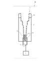
- FIG. 6 is a schematic conceptual diagram schematically showing the first embodiment of the biological sample electrical measurement apparatus 10 according to the present technology.
- the electrical measurement cartridge 1 see A in FIG. 2 according to the first embodiment described above is used.
- the electrical measurement apparatus 10 for biological samples according to the present technology is roughly provided with at least the above-described electrical measurement cartridge 1, the cartridge insertion unit 2, the application unit 3, and the measurement unit 4. Moreover, the guided part 5, the analysis part 6, etc. can further be provided as needed. Hereinafter, each part will be described in detail. Note that the electrical measurement cartridge 1 is the same as that described above, and a description thereof will be omitted here.
- the cartridge insertion part 2 is a part into which the electrical measurement cartridge 1 according to the present technology is inserted.
- the cartridge insertion portion 2 can be freely designed according to the form of the electrical measurement cartridge 1 and the like.
- the cartridge insertion portion 2 can be provided with a temperature adjustment mechanism.
- the temperature adjustment mechanism is a mechanism that keeps the temperature of the biological sample S held in the biological sample holding unit 11 constant. Since the biological sample electrical measurement apparatus 10 includes the temperature adjustment mechanism, the temperature of the biological sample S becomes constant, and measurement errors caused by temperature changes of the biological sample S can be reduced.
- the specific configuration of the temperature adjustment mechanism is not particularly limited, and examples thereof include forming the cartridge insertion portion 2 with a material capable of keeping warm.
- the application unit 3 is a part that applies a voltage to the connection unit 13 of the electrical measurement cartridge 1 according to the present technology. Specifically, the application unit 3 starts from the time when an instruction to start measurement is received or when the power of the biological sample electrical measurement device 10 is turned on, and the connection unit of the electrical measurement cartridge 1 A voltage is applied to 13. In this case, the application unit 3 applies an AC voltage having a predetermined frequency to the connection unit 13 at each set measurement interval. Note that the voltage applied by the application unit 3 can be a DC voltage according to the electrical characteristics to be measured.
- the measurement unit 4 is a part that measures the electrical characteristics of the biological sample S.
- a complex dielectric constant (hereinafter also referred to as “dielectric constant”) is defined as a start time when a command to start measurement is received or when a power source of the biological sample electrical measurement apparatus 10 is turned on. And electrical characteristics such as frequency dispersion.
- the measurement unit 4 measures the current or impedance between the electrodes 12 of the electrical measurement cartridge 1 at a predetermined period, and derives the dielectric constant from the measured value.
- a known function or relational expression indicating the relationship between current or impedance and dielectric constant can be used.
- the electrical measurement cartridge 1 includes the guide portion 15 as shown in the second embodiment of FIG. 3, the biological sample electrical measurement device 10 is shown in the second embodiment of FIG. 7.
- a guided portion 5 can be further provided.
- the guided portion 5 is a portion to which the guide portion 15 is engaged.
- the biological sample electrical measurement device 10 includes the guided portion 5, the electrical measurement cartridge 1 can be smoothly inserted into the biological sample electrical measurement device 10, and the convenience for the user is improved. Further, when a positioning mechanism described later is configured using the guide portion 15 and the guided portion 5, the position of the electrical measurement cartridge 1 in the biological sample electrical measurement device 10 can be accurately determined. Measurement errors due to the displacement of the position of the measurement cartridge 1 can also be reduced.
- the biological sample electrical measurement apparatus 10 can further include an analysis unit 6 as shown in the second embodiment of FIG.
- the analysis unit 6 is a part that receives the electrical characteristic data of the biological sample S derived from the measurement unit 4 and determines the physical properties of the biological sample S.
- the electrical characteristic data of the biological sample S derived from the measurement unit 4 is given to the analysis unit 6 at every measurement interval, and the analysis unit 6 receives the electrical characteristic data given from the measurement unit 4.
- the physical property determination of the biological sample S is started. Further, the analysis unit 6 notifies the result of physical property determination of the biological sample S and / or dielectric constant data. This notification can be performed, for example, by graphing and displaying on a monitor or printing on a predetermined medium.
- the biological sample electrical measurement device 10 may include a positioning mechanism.
- the positioning mechanism is a mechanism that determines the position of the electrical measurement cartridge 1. Since the biological sample electrical measurement apparatus 10 includes the positioning mechanism, the position of the electrical measurement cartridge 1 in the biological sample electrical measurement apparatus 10 can be accurately determined. Since the contact position becomes accurate, a measurement error due to the positional deviation of the electrical measurement cartridge 1 can be reduced.
- the specific configuration of the positioning mechanism is not particularly limited.
- a positioning pin that positions the electrical measurement cartridge 1 with respect to the biological sample electrical measurement device 10 in the height direction may be used. It is done.
- the positioning mechanism may be configured using the guide portion 15 and the guided portion 5.
- the biological sample electrical measurement apparatus 10 can also include a seal release mechanism.
- the seal release mechanism is a mechanism that releases the sealed state of at least a part of the biological sample holding unit 11. Since the biological sample electrical measurement device 10 includes the sealing release mechanism, an unnecessary impact is applied to the electrical measurement cartridge 1 or an extra external force is applied to the biological sample holding unit 11 or the sealing unit 16. The risk of being reduced.
- the specific configuration of the seal release mechanism is not particularly limited.
- the electrical measurement cartridge 1 includes a fixing mechanism (for example, the notch 111 and the claw 161), heat or the like is used.
- the fixation of the biological sample holding part 11 and the sealing part 16 by the fixing mechanism may be released by using a chemical means or a physical means. More specifically, for example, when the electrical measurement cartridge 1 is inserted into the cartridge insertion portion 2, a method of setting a release pin on the biological sample electrical measurement device 10 side may be used.
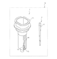
- FIG. 8 is a schematic diagram schematically illustrating the first embodiment of the electrical measurement kit K according to the present technology.
- the electrical measurement cartridge 1 according to the first embodiment described above is used.
- the electrical measurement kit K according to the present technology is roughly divided into at least the electrical measurement cartridge 1 and the biological sample introduction member 7 described above. Details will be described below. Note that the electrical measurement cartridge 1 is the same as that described above, and a description thereof will be omitted here.
- the biological sample introduction member 7 is a member for introducing the biological sample S into the biological sample holding unit 11.
- a pipette tip 71 can be used. More specifically, the biological sample S can be introduced by providing the biological sample electrical measurement apparatus 10 with a suction mechanism (such as a pipetter) and attaching a pipette tip 71 to the suction mechanism.
- the biological sample introduction member 7 is not limited to the pipette-shaped tip 71 illustrated in FIG. 8, and may be all or a part of an instrument that can introduce the biological sample S into the biological sample holding unit 11.
- it can be freely selected according to the type of biological sample S, the measurement method, the electrical measurement device used, and the like.
- an injection needle can be used in addition to the pipette tip 71.
- the biological sample introduction member 7 can be made disposable as in the case of the electrical measurement cartridge 1. By making the biological sample introduction member 7 disposable, it is possible to save troubles such as cleaning of the instrument used for introducing the biological sample S, and to improve the convenience of the user and increase the efficiency of measurement. . In addition, it is possible to prevent the occurrence of measurement errors due to another biological sample S remaining in the instrument used for introducing the biological sample S, and the measurement accuracy during electrical measurement is improved.
- the electrical measurement cartridge 1 according to the present technology can be suitably used for an electrical measurement method for a biological sample that measures the electrical characteristics of the biological sample S.
- the measurable electrical characteristics are not particularly limited, and can be freely measured according to the type of the biological sample S, physical properties to be analyzed, and the like. For example, dielectric constant, impedance, etc. can be measured.
- the blood coagulation state and the blood sedimentation state can be analyzed from measured values of dielectric constant and impedance. More specifically, a parameter indicating each characteristic is extracted from a plurality of measured values of dielectric constant and / or impedance received during the analysis period, and this parameter is used as a reference for the enhancement of blood coagulation ability and the progress of blood precipitation process. Based on the comparison with the determined reference value, the blood coagulation situation and the blood sedimentation situation can be analyzed. Therefore, the measurement accuracy in electrical measurement is improved.
- this technique can also take the following structures.
- a biological sample holding unit for storing the biological sample; At least a pair of electrodes fixed to the biological sample holder; A connection part for electrically connecting the electrode and an external circuit; A protection part for protecting the connection part;
- An electrical measurement cartridge comprising at least.
- the electrical measurement cartridge according to (1) further comprising a guide unit that is fixed to the biological sample holding unit and guides the insertion of the cartridge into the biological sample electrical measurement device.
- the electrical measurement cartridge according to (2), wherein the guide portion also functions as the protection portion.
- the resin is one or more resins selected from polypropylene, polystyrene, acrylic, and polysulfone.
- An electrical measurement device for a biological sample that measures electrical characteristics of the biological sample A biological sample holding unit for storing the biological sample; at least a pair of electrodes fixed to the biological sample holding unit; a connection unit for electrically connecting the electrode and an external circuit; and a protection unit for protecting the connection unit
- a cartridge insertion part for inserting an electrical measurement cartridge An application unit for applying a voltage to the connection unit;
- An electrical measurement apparatus for biological samples comprising at least (10)
- the electrical measurement cartridge includes a guide unit that is fixed to the biological sample holding unit and guides insertion of the cartridge into the biological sample electrical measurement device.
- a biological sample holding unit for storing the biological sample; At least a pair of electrodes fixed to the biological sample holder; A connection part for electrically connecting the electrode and an external circuit; A protection part for protecting the connection part; An electrical measurement method for a biological sample, wherein an electrical characteristic of the biological sample is measured using an electrical measurement cartridge comprising at least.
Landscapes
- Health & Medical Sciences (AREA)
- Chemical & Material Sciences (AREA)
- Life Sciences & Earth Sciences (AREA)
- Hematology (AREA)
- Analytical Chemistry (AREA)
- General Health & Medical Sciences (AREA)
- Immunology (AREA)
- Chemical Kinetics & Catalysis (AREA)
- Engineering & Computer Science (AREA)
- Biochemistry (AREA)
- General Physics & Mathematics (AREA)
- Physics & Mathematics (AREA)
- Pathology (AREA)
- Molecular Biology (AREA)
- Biomedical Technology (AREA)
- Urology & Nephrology (AREA)
- Electrochemistry (AREA)
- Clinical Laboratory Science (AREA)
- Microbiology (AREA)
- Cell Biology (AREA)
- Biotechnology (AREA)
- Food Science & Technology (AREA)
- Medicinal Chemistry (AREA)
- Investigating Or Analyzing Materials By The Use Of Electric Means (AREA)
- Investigating Or Analysing Biological Materials (AREA)
Abstract
接続部への接触のリスクを低減できる電気的測定用カートリッジを提供すること。 生体試料を収容する生体試料保持部と、前記生体試料保持部に固定された少なくとも一対の電極と、前記電極と外部回路とを電気的に接続する接続部と、前記接続部を保護する保護部と、を少なくとも備える電気的測定用カートリッジを提供する。
Description
本技術は、生体試料の電気的特性測定のための電気的測定用カートリッジに関する。より詳しくは、接続部への接触のリスクを低減できる電気的測定用カートリッジ、該電気的測定用カートリッジを用いた生体試料用電気的測定装置及び生体試料用電気的測定方法に関する。
生体試料の電気的特性を測定し、その測定結果から生体試料の物性を判定したり、生体試料に含まれる細胞等の種類を判別したりすることが行われている(例えば、特許文献1参照)。測定される電気的特性としては、複素誘電率やその周波数分散(誘電スペクトル)などが挙げられる。複素誘電率やその周波数分散は、一般に、溶液に対して電圧を印加するための電極を備えた溶液保持器等を用いて電極間の複素キャパシタンスないし複素インピーダンスを測定することで算出される。
また、例えば、特許文献2には、血液の誘電率から血液凝固に関する情報を取得する技術が開示されており、「一対の電極と、上記一対の電極に対して交番電圧を所定の時間間隔で印加する印加手段と、上記一対の電極間に配される血液の誘電率を測定する測定手段と、血液に働いている抗凝固剤作用が解かれた以後から上記時間間隔で測定される血液の誘電率を用いて、血液凝固系の働きの程度を解析する解析手段と、を有する血液凝固系解析装置」が記載されている。
生体試料の電気的測定用容器としては、例えば、特許文献3に、液体状の生体試料を収容するための樹脂からなる生体試料保持部と、該生体試料保持部に固定された電気伝導部と、を少なくとも備え、前記電気伝導部の一部が前記生体試料保持部に埋入された状態で、前記生体試料保持部と前記電気伝導部が一体成形された液体状の生体試料の電気的測定用容器が開示されている。
しかし、特許文献3に開示された容器は、電気伝導部の一部である接続部が被覆されておらず、露出した状態となっている。したがって、使用者が特許文献3に開示された容器を用いて生体試料の電気的特性測定を行う際や、製造従事者が特許文献3に開示された容器を製造する際などに、誤って該接続部に接触するリスクが非常に高い。
使用者や製造従事者などの手指が該接続部に誤って接触した場合、切り傷などの受傷の可能性があり、製品の安全性の観点から問題がある。また、該接続部に余分な外力が加わることで、輸送時などに該接続部が変形、破損するといったリスクや、該接続部により製品の包装を突き破るといったリスクも考えられる。更には、空気中のゴミ等の予期しない物質が該接続部に付着し、電気的特性測定の際の測定精度が低下するという問題もある。
前述の通り、従来の生体試料の電気的測定用容器では接続部が露出しており、該接続部への接触のリスクを低減させることが困難であった。
そこで、本技術では、接続部への接触のリスクを低減できる電気的測定用カートリッジを提供することを主目的とする。
本願発明者らは、前記課題を解決するために、電気的特性を測定する際に用いるカートリッジの構造について鋭意研究を行った結果、該カートリッジが接続部を保護する保護部を備えることで、該接続部への接触のリスクを低減させることに成功し、本技術を完成するに至った。
すなわち、本技術では、まず、生体試料を収容する生体試料保持部と、
前記生体試料保持部に固定された少なくとも一対の電極と、
前記電極と外部回路とを電気的に接続する接続部と、
前記接続部を保護する保護部と、
を少なくとも備える電気的測定用カートリッジを提供する。
また、本技術に係る電気的測定用カートリッジは、前記生体試料保持部に固定され、生体試料用電気的測定装置への前記カートリッジの挿入を案内するガイド部を備えることもできる。
更に、前記ガイド部は、前記保護部としても機能することができる。
加えて、本技術に係る電気的測定用カートリッジは、前記生体試料保持部の一部に、試薬を封入することもできる。
また、前記生体試料保持部及び/又は前記保護部の材料は特に限定されないが、樹脂を用いることができる。
更に、前記樹脂の種類も特に限定されないが、ポリプロピレン、ポリスチレン、アクリル、及びポリサルホンから選ばれる一種以上の樹脂を用いることができる。
本技術において、前記生体試料は、血液試料とすることができる。
また、前記生体試料を血液試料とした場合、本技術に係る電気的測定用カートリッジは、血液凝固状態の測定用に用いることもできる。
また、本技術では、生体試料の電気的特性を測定する生体試料用電気的測定装置であって、
生体試料を収容する生体試料保持部と、前記生体試料保持部に固定された少なくとも一対の電極と、前記電極と外部回路とを電気的に接続する接続部と、前記接続部を保護する保護部と、を少なくとも備える電気的測定用カートリッジを挿入するカートリッジ挿入部と、
前記接続部に電圧を印加する印加部と、
前記生体試料の電気的特性を測定する測定部と、
を少なくとも備える生体試料用電気的測定装置も提供する。
また、本技術に係る生体試料用電気的測定装置は、前記電気的測定用カートリッジが、前記生体試料保持部に固定され、生体試料用電気的測定装置への前記カートリッジの挿入を案内するガイド部を備える場合、前記カートリッジ挿入部は、前記ガイド部が係合される被ガイド部を備えることもできる。
更に、本技術では、生体試料を収容する生体試料保持部と、
前記生体試料保持部に固定された少なくとも一対の電極と、
前記電極と外部回路とを電気的に接続する接続部と、
前記接続部を保護する保護部と、
を少なくとも備える電気的測定用カートリッジを用いて、前記生体試料の電気的特性を測定する生体試料用電気的測定方法も提供する。
前記生体試料保持部に固定された少なくとも一対の電極と、
前記電極と外部回路とを電気的に接続する接続部と、
前記接続部を保護する保護部と、
を少なくとも備える電気的測定用カートリッジを用いて、前記生体試料の電気的特性を測定する生体試料用電気的測定方法も提供する。
本技術に係る電気的測定用カートリッジは、接続部を保護する保護部を備えているため、該接続部への接触のリスクを低減できる。なお、ここに記載された効果は、必ずしも限定されるものではなく、本技術中に記載されたいずれかの効果であってもよい。
以下、本技術を実施するための好適な形態について、図面を参照しながら説明する。なお、以下に説明する実施形態は、本技術の代表的な実施形態の一例を示したものであり、これにより本技術の範囲が狭く解釈されることはない。なお、説明は以下の順序で行う。
1.電気的測定用カートリッジ1
(1)生体試料保持部11
(2)電極12
(3)接続部13
(4)保護部14
(5)ガイド部15
(6)封止部16
(7)生体試料S
(8)試薬R
(9)その他
(a)切欠き部111
(b)ツメ161
2.生体試料用電気的測定装置10
(1)カートリッジ挿入部2
(2)印加部3
(3)測定部4
(4)被ガイド部5
(5)解析部6
(6)その他
3.生体試料用電気的測定用キットK
(1)生体試料導入用部材7
4.生体試料用電気的測定方法
1.電気的測定用カートリッジ1
(1)生体試料保持部11
(2)電極12
(3)接続部13
(4)保護部14
(5)ガイド部15
(6)封止部16
(7)生体試料S
(8)試薬R
(9)その他
(a)切欠き部111
(b)ツメ161
2.生体試料用電気的測定装置10
(1)カートリッジ挿入部2
(2)印加部3
(3)測定部4
(4)被ガイド部5
(5)解析部6
(6)その他
3.生体試料用電気的測定用キットK
(1)生体試料導入用部材7
4.生体試料用電気的測定方法
1.電気的測定用カートリッジ1
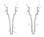
図1は、本技術に係る電気的測定用カートリッジ1の第1実施形態を模式的に示す模式図である。図2のAは、図1の矢印a方向から視た場合の端面模式図であり、図2のBは、図1の矢印b方向から視た場合の端面模式図である。
図1は、本技術に係る電気的測定用カートリッジ1の第1実施形態を模式的に示す模式図である。図2のAは、図1の矢印a方向から視た場合の端面模式図であり、図2のBは、図1の矢印b方向から視た場合の端面模式図である。
本技術に係る電気的測定用カートリッジ1は、生体試料Sの電気的特性を測定する際に、該生体試料Sを保持するために用いるカートリッジである。本技術に係る電気的測定用カートリッジ1は、大別して、生体試料保持部11と、電極12と、接続部13と、保護部14と、を少なくとも備える。また、必要に応じて、ガイド部15、封止部16などを更に備えることもできる。以下、各部位について詳細に説明する。なお、一部の図面において、説明上、生体試料Sを図示しているが、生体試料Sは、本技術に係る電気的測定用カートリッジ1に、常に包含されるわけではない。
(1)生体試料保持部11
生体試料保持部11は、測定対象である生体試料Sを収容する部位である。
生体試料保持部11は、測定対象である生体試料Sを収容する部位である。
本技術に係る電気的測定用カートリッジ1において、生体試料保持部11の形態は特に限定されず、生体試料Sの種類や測定方法、用いる電気的測定装置などに応じて自由に設計することができる。例えば、円筒体、断面が多角(三角、四角或いはそれ以上)の多角筒体、円錐体、断面が多角(三角、四角或いはそれ以上)の多角錐体、或いはこれらを1種又は2種以上組み合わせた形態などが挙げられる。
本技術において、生体試料保持部11の形態は、少なくとも後述する電極12を配置する部分が平面状となるような形態を選択することが好ましい。その理由について、以下、詳細に説明する。
一般的に、電気的測定の際に用いられる電極は、平面状や板状の形態であることが多い。生体試料保持部11において、円筒状の形態を選択した場合、湾曲した部分に平面状や板状の電極12を取り付けることとなるため、製造工程が非常に煩雑となる。また、生体試料保持部11の湾曲した部分に平面状や板状の電極12を取り付けると、生体試料保持部11と電極12との接続部に段差が生じる可能性が高く、電気的測定の際の測定精度が低下する場合がある。したがって、生体試料保持部11において、少なくとも電極12を配置する部分が平面状となるような形態を選択することで、電気的測定用カートリッジ1の製造工程の簡素化及び測定精度の向上が実現できる。
本技術において、生体試料Sは、生体試料保持部11に保持された状態で各種電気的測定が行われる。そのため、生体試料保持部11は、生体試料Sを保持した状態で密封可能な構成であることが好ましい。ただし、生体試料Sの各種電気的特性を測定するのに要する時間を停滞可能であって、測定に影響がなければ、密封可能な構成でなくてもよい。
生体試料保持部11への生体試料Sの具体的な導入又は密閉方法は特に限定されず、生体試料保持部11の形態に応じて自由な方法で導入又は密閉することが可能である。例えば、生体試料保持部11にピペットなどを用いて導入する方法や、生体試料保持部11の外表面から注射針を穿入し、生体試料Sを注入した後、注射針の貫通部分をグリスなどで塞ぐことで密閉する方法などが挙げられる。
本技術に係る生体試料保持部11に用いることのできる材料は特に限定されないが、本技術では、樹脂を用いて生体試料保持部11を形成することができる。
また、生体試料保持部11に用いることのできる樹脂の種類は特に限定されず、生体試料Sの保持に適用可能な樹脂を、1種又は2種以上自由に選択して用いることができる。例えば、ポリプロピレン、ポリメチルメタクリレート、ポリスチレン、アクリル、ポリサルホン、ポリテトラフルオロエチレンなどの疎水性かつ絶縁性のポリマーやコポリマー、ブレンドポリマーなどが挙げられる。
本技術では、この中でも特に、ポリプロピレン、ポリスチレン、アクリル、及びポリサルホンから選ばれる一種以上の樹脂で生体試料保持部11を形成することが好ましい。これらの樹脂は、血液に対して低凝固活性であるという性質を有するため、例えば、生体試料Sとして血液試料を選択した場合の測定などに好適に用いることができるからである。
(2)電極12
電極12は、生体試料保持部11に固定され、少なくとも一対の電極からなる部位である。電極12は、生体試料Sの状態を電気的に測定するため、電気的測定時に生体試料Sと接触し、生体試料Sに必要な電圧を印加する。
電極12は、生体試料保持部11に固定され、少なくとも一対の電極からなる部位である。電極12は、生体試料Sの状態を電気的に測定するため、電気的測定時に生体試料Sと接触し、生体試料Sに必要な電圧を印加する。
本技術に係る電気的測定用カートリッジ1は、生体試料Sの種類や測定方法、用いる電気的測定装置などに応じて一対以上の電極12を備えることもできる。例えば、生体試料Sの誘電率やインピーダンスを測定する場合、一対以上の電極12を生体試料保持部11に対して設計することができる。この場合、生体試料Sの電気的特性を測定する上で、電極12を平行に配置することが好ましい。ただし、例えば、インサート成型などを行う場合の離型性などを考慮して、数度の傾きを持たせた状態で電極12を配置することもできる。
電極12の配置や形態などは特に限定されず、生体試料Sに必要な電圧を印加することができれば、生体試料保持部11の形態や測定方法、用いる電気的測定装置などに応じて自由に設計することができる。本技術では、特に、測定効率を向上させる観点から、電極12は平面的に生体試料Sに接することが好ましい。生体試料保持部11の内側壁に段差があると、気泡などがその段差部分に留まってしまったり、段差部分に試薬濃度のムラができたりして、測定値に悪影響を及ぼす可能性があるからである。生体試料保持部11と電極12との接続箇所が平滑になるようにすることで、気泡や試料濃度ムラなどによる悪影響を排除し、電気的測定の際の測定精度を向上させることができる。
電極12が平面的に生体試料Sに接するための具体的な方法は特に限定されず、例えば、電極12を幅広に形成することで、電極12が生体試料Sに対して平面的に接するようにする方法などが挙げられる。
本技術において、電極12を生体試料保持部11に固定する方法は特に限定されないが、電極12の一部を生体試料保持部11に埋入した状態で、生体試料保持部11と電極12とを一体成形する方法が好ましい。その理由について、以下、詳細に説明する。
例えば、接着剤を用いて電極12を生体試料保持部11に固定する場合、用いる接着剤の種類によっては、生体試料Sの性質に悪影響を及ぼす場合がある。例えば、生体試料Sとして血液を選択した場合、用いる接着剤の種類によっては、血液凝固活性が促進されてしまい、目的とする測定に悪影響を及ぼす。しかし、生体試料保持部11と電極12とを一体成形する方法、すなわち、生体試料保持部11と電極12との固定に接着剤などの固定材料を用いない方法をとることで、接着剤などの固定材料による生体試料Sへの悪影響を排除でき、電気的測定の際の測定精度が向上する。
仮に、生体試料Sへの影響が少ない固定材料を用いた場合であっても、生体試料Sを収容するためのカートリッジを製造する際に、固定材料による接着工程が増えることから、生産性に劣る。しかし、生体試料保持部11と電極12とを一体成形する方法をとることで、生体試料保持部11の成形工程に加えて、接着工程を別途設ける必要がない。そのため、電気的測定用カートリッジ1の製造が容易となり、本技術に係る電気的測定用カートリッジ1を安価かつ大量に生産することができる。
本技術において、生体試料保持部11と電極12とを一体成形する具体的な方法は特に限定されず、自由な方法をとることができる。例えば、生体試保持部11を樹脂により形成した場合、樹脂が溶融状態から固化する際に電極12を所定位置に配置することで、生体試料保持部11と電極12とを一体成形することができる。より具体的には、金型内に電極12を挿入し、その周りに樹脂を注入して電極12と樹脂とを一体化する、所謂、インサート成型により、生体試料保持部11と電極12とを一体成形する方法などが挙げられる。
また、生体試料保持部11の成形を行う際に、同時に電極12を生体試料保持部11に固定することで、電気的測定用カートリッジ1の製造工程の簡易化を図ることができる。したがって、本技術に係る電気的測定用カートリッジ1を安価かつ大量に生産することができる。この特徴を利用して、例えば、本技術に係る電気的測定用カートリッジ1を使い捨てにすることも可能である。本技術に係る電気的測定用カートリッジ1を使い捨てにすることで、カートリッジの洗浄などの手間を省くことができ、測定の効率化を図ることができる。また、カートリッジ内に残留した別の生体試料Sに起因する測定誤差などの発生を防止でき、電気的測定の際の測定精度が向上する。
更に、非常に稀ではあるが、樹脂と電気伝導性素材とのひずみの違いなどから、温度などの保管条件や測定条件によっては、生体試料保持部11と電極12との境界部から生体試料Sが漏れ出す場合がある。そこで、電極12において、生体試料保持部11に固定された部分の構造の一部に曲折する部分を備えることで、曲折する部分を備えない場合と比べて、生体試料保持部11と電極12との境界からの生体試料Sの漏れ出しを、より確実に防止することができる。また、生体試料保持部11と電極12との固定がより強固となり、頑丈な電気的測定用カートリッジ1を形成することもできる。
加えて、本技術に係る電気的測定用カートリッジ1は、図3の第2実施形態に示すように、一対の電極12のカートリッジ外側部分に、樹脂を備えない構成(図3のX参照)をとることもできる。このような構造をとることで、例えば、生体試料保持部11の成形時に、電極12をマグネットなどの磁気的手段を用いて位置決め固定することで、電極12を電気的測定用カートリッジ1の所望の位置に対して、正確に位置決めすることができる。また、生体試料保持部11の成形時に電極12が保持され、電極12の変形を防止することもできる。
なお、カートリッジ外部からの電極12の固定手段として、前述したような磁気的手段に限らず、カートリッジ外部から電極12を固定することができる手段であれば、あらゆる手段を用いることができる。
(3)接続部13
接続部13は、電極12と外部回路とを電気的に接続する部位である。したがって、本技術において、接続部13の一部は、図1の第1実施形態などに示すように、電極12と繋がった構造をとる。
接続部13は、電極12と外部回路とを電気的に接続する部位である。したがって、本技術において、接続部13の一部は、図1の第1実施形態などに示すように、電極12と繋がった構造をとる。
接続部13の配置や形態などは特に限定されず、外部回路と電気的に接続することができれば、生体試料保持部11の形態や測定方法、用いる電気的測定装置などに応じて自由に設計することができる。
本技術において、電極12及び接続部13は、電気伝導性材料からなる。電極12及び接続部13に用いられる電気伝導性材料の種類は特に限定されず、生体試料Sの電気的特性の測定に適用可能な材料を、1種又は2種以上自由に選択して用いることができる。例えば、チタン、アルミニウム、ステンレス、白金、金、銅、黒鉛などが挙げられる。
本技術では、この中でも特に、チタンを含む電気伝導性材料で電極12及び接続部13を形成することが好ましい。チタンは、血液に対して低凝固活性であるという性質を有するため、例えば、生体試料Sとして血液試料を選択した場合の測定などに好適に用いることができるからである。
(4)保護部14
保護部14は、接続部13を保護する部位である。
保護部14は、接続部13を保護する部位である。
前述の通り、従来の生体試料の電気的測定用容器では接続部が露出しており、使用者や製造従事者などが、誤って該接続部に接触するリスクが非常に高かった。本技術に係る電気的測定用カートリッジ1は、接続部13を保護する保護部14を備えているため、使用者や製造従事者などが接続部13へ接触するリスクを低減できる。そのため、使用者や製造従事者などの手指が接続部13に誤って接触することが減り、切り傷などの受傷の可能性も低下する。したがって、本技術に係る電気的測定用カートリッジ1は、製品の安全性の観点から、非常に有用である。
また、保護部14により輸送時などに接続部13が変形、破損するといったリスクや、接続部13により製品の包装を突き破るといったリスクも回避できる。更には、保護部14により空気中のゴミ等の予期しない物質が接続部13に付着する可能性も低下し、電気的測定の際の測定精度を向上させることもできる。
保護部14の配置や形態などは特に限定されず、接続部13を保護することができれば、生体試料保持部11の形態や測定方法、用いる電気的測定装置などに応じて自由に設計することができるが、前述の通り、接続部13は電極12と外部回路とを電気的に接続する部位である。したがって、本技術において、接続部13を保護部14で完全に被覆するような形態をとることはできない。そのため、例えば、図1の第1実施形態などに示すように、接続部13が外部回路とコンタクトすることを妨げない程度に、保護部14の少なくとも一部に、開口箇所を設ける必要がある。
本技術に係る保護部14に用いることのできる材料は特に限定されないが、本技術では、樹脂を用いて保護部14を形成することができる。
また、保護部14に用いることのできる樹脂の種類は特に限定されず、生体試料Sの保持に適用可能な樹脂を、1種又は2種以上自由に選択して用いることができる。例えば、ポリプロピレン、ポリメチルメタクリレート、ポリスチレン、アクリル、ポリサルホン、ポリテトラフルオロエチレンなどの疎水性かつ絶縁性のポリマーやコポリマー、ブレンドポリマーなどが挙げられる。
本技術では、この中でも特に、ポリプロピレン、ポリスチレン、アクリル、及びポリサルホンから選ばれる一種以上の樹脂で保護部14を形成することが好ましい。これらの樹脂は、血液に対して低凝固活性であるという性質を有するため、例えば、生体試料Sとして血液試料を選択した場合の測定などに好適に用いることができるからである。
なお、図1に示す第1実施形態では、左右の保護部14の大きさを同一にしているが、左右の保護部14の大きさを異なる大きさとしてもよい。左右の保護部14の大きさを異なる大きさとすることで、例えば、電気的測定用カートリッジ1にバーコードなどを付けて管理する場合、バーコードなどを付ける位置の目印とすることができ、使用者の利便性が向上する。
(5)ガイド部15
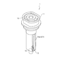
本技術に係る電気的測定用カートリッジ1は、図3の第2実施形態に示すように、更にガイド部15を備えることができる。ガイド部15は、生体試料用電気的測定装置への電気的測定用カートリッジ1の挿入を案内する部位である。
本技術に係る電気的測定用カートリッジ1は、図3の第2実施形態に示すように、更にガイド部15を備えることができる。ガイド部15は、生体試料用電気的測定装置への電気的測定用カートリッジ1の挿入を案内する部位である。
電気的測定用カートリッジ1がガイド部15を備えることで、生体試料用電気的測定装置への挿入がスムーズとなる。また、例えば、電気的測定用カートリッジ1にバーコードなどを付けて管理する場合、バーコードなどを付ける位置の目印とすることができる。したがって、使用者の利便性を向上させることが可能となる。
また、ガイド部15を用いて、後述する位置決め機構を構成した場合、生体試料用電気的測定装置における電気的測定用カートリッジ1の位置を正確に決めることができ、電気的測定用カートリッジ1の位置のズレに起因する測定誤差を低減させることができる。
また、本技術では、ガイド部15は、図4の第3実施形態に示すように、保護部14として機能することもできる。これにより、保護部14とガイド部15を同時に形成することができるため、製造工程を別途設ける必要がない。そのため、電気的測定用カートリッジ1の製造が容易となり、本技術に係る電気的測定用カートリッジ1を安価かつ大量に生産することができる。また、生体試料用測定装置側の構成も簡易化することができるため、装置の小型化や低価格化にも貢献できる。
本技術に係る電気的測定用カートリッジ1は、必要に応じて、更に生体試料保持部11の一部に試薬Rを封入することができる。本技術において、試薬Rを封入する方法は特に限定されないが、例えば、以下に説明する、封止部16を更に備える方法などが挙げられる。
(6)封止部16
図4は、本技術に係る電気的測定用カートリッジ1の第3実施形態を模式的に示す模式図であり、封止部16を更に備えている。封止部16とは、生体試料保持部11の少なくとも一部を密封する部位である。
図4は、本技術に係る電気的測定用カートリッジ1の第3実施形態を模式的に示す模式図であり、封止部16を更に備えている。封止部16とは、生体試料保持部11の少なくとも一部を密封する部位である。
本技術に係る電気的測定用カートリッジ1が封止部16を備えることで、生体試料保持部11の密封部分に試薬Rを封入することができる。
本技術に係る電気的測定用カートリッジ1が封止部16を備える場合、封止部16の形態は、生体試料保持部11の一部を密封可能であれば特に限定されず、生体試料Sの種類や測定方法、用いる電気的測定装置などに応じて自由に設計することができる。例えば、円筒体、断面が多角(三角、四角或いはそれ以上)の多角筒体、円錐体、断面が多角(三角、四角或いはそれ以上)の多角錐体、或いはこれらを1種又は2種以上組み合わせた形態などが挙げられる。
また、封止部16に用いることのできる材料は特に限定されず、生体試料保持部11と同様に、樹脂を用いて形成することができる。なお、樹脂の種類については、前述したものと同様であるため、ここでは説明を割愛する。
本技術に係る電気的測定用カートリッジ1が封止部16を備える場合、封止部16が生体試料保持部11の密封部分と電極12とを間断するように設計することが好ましい。測定精度が低下する原因となるような空気中のゴミ等が、電極12へ付着したりすることを回避できるからである。また、予め生体試料保持部11の一部に試薬Rを封入した状態で電気的測定用カートリッジ1を保存、運搬等する場合、試薬Rが生体試料保持部11の内側壁や電極12へ飛び散るのを防止することができる。そのため、電気的特性測定の際に、生体試料Sに対して有効な試薬量を維持し、かつ、電極12に残留した試薬Rに起因する測定誤差などを低減させることができる。
なお、本技術に係る電気的測定用カートリッジ1が封止部16を備える場合、電気的特性測定の際には、電気的特性測定用カートリッジ1は、生体試料保持部11に生体試料Sを保持し、また、封止部16は取り除かれた状態となる。
(7)生体試料S
本技術で測定対象とすることが可能な生体試料Sは特に限定されず、自由に選択することができる。例えば、全血、血漿、又はこれらの希釈液及び/又は薬剤添加物等の血液成分を含有する血液試料などが挙げられる。また、生体試料Sとして血液試料を選択した場合、本技術に係る電気的測定用カートリッジ1は、血液凝固状態の測定用に用いることも可能である。
本技術で測定対象とすることが可能な生体試料Sは特に限定されず、自由に選択することができる。例えば、全血、血漿、又はこれらの希釈液及び/又は薬剤添加物等の血液成分を含有する血液試料などが挙げられる。また、生体試料Sとして血液試料を選択した場合、本技術に係る電気的測定用カートリッジ1は、血液凝固状態の測定用に用いることも可能である。
(8)試薬R
本技術に係る電気的測定用カートリッジ1が生体試料保持部11の一部に試薬Rを封入することができる場合、生体試料保持部11の一部に封入することが可能な試薬Rは特に限定されず、自由に選択することができる。例えば、気体状、固体状、液体状などの試薬が挙げられる。より具体的には、生体試料Sとして血液試料を選択した場合、抗凝固剤、凝固開始剤などが挙げられる。
本技術に係る電気的測定用カートリッジ1が生体試料保持部11の一部に試薬Rを封入することができる場合、生体試料保持部11の一部に封入することが可能な試薬Rは特に限定されず、自由に選択することができる。例えば、気体状、固体状、液体状などの試薬が挙げられる。より具体的には、生体試料Sとして血液試料を選択した場合、抗凝固剤、凝固開始剤などが挙げられる。
本技術に係る電気的測定用カートリッジ1が生体試料保持部11の一部に試薬Rを封入することができる場合、電気的測定用カートリッジ1は、予め試薬Rを封入した状態で、運搬、保存等を行うことも可能である。この場合、測定を行う直前に電気的測定用カートリッジ1を開栓し、生体試料保持部11に測定対象とする生体試料Sを導入する工程のみで、直ちに測定を開始できる。したがって、測定精度の低下の原因となるような空気中のゴミ等が、生体試料保持部11に混入することを回避でき、測定精度が向上する。更には、測定開始までの作業工程が減り、使用者の利便性も向上する。
また、試薬Rとして用いられる試薬の種類によっては、試薬Rを封入した状態で、電気的測定用カートリッジ1を冷蔵、凍結、凍結乾燥などの方法により一時的に保存することも可能である。
(9)その他
本技術に係る電気的測定用カートリッジ1は、電気的測定用カートリッジ1が封止部16を備える場合、固定機構を備えることも可能である。本技術において、固定機構とは、封止部16が生体試料保持部11の少なくとも一部を密封する際に、生体試料保持部11と封止部16とを固定する機構である。電気的測定用カートリッジ1が固定機構を備えることで、封止部16の生体試料保持部11からの脱離を防止でき、安定的に生体試料保持部11の一部と封止部16との密封状態を維持できる。
本技術に係る電気的測定用カートリッジ1は、電気的測定用カートリッジ1が封止部16を備える場合、固定機構を備えることも可能である。本技術において、固定機構とは、封止部16が生体試料保持部11の少なくとも一部を密封する際に、生体試料保持部11と封止部16とを固定する機構である。電気的測定用カートリッジ1が固定機構を備えることで、封止部16の生体試料保持部11からの脱離を防止でき、安定的に生体試料保持部11の一部と封止部16との密封状態を維持できる。
固定機構の具体的な構成は特に限定されず、例えば、図5の第4実施形態に示すように、生体試料保持部11に設けられた切欠き部111と、切欠き部111に嵌合し、かつ、封止部16に設けられたツメ161と、で構成することなどが挙げられる。また、ガイド部15が切欠き部111として機能してもよい。
また、固定機構は、固定解除後に再固定不能となるように設計することもできる。固定解除後に再固定不能となることで、一度開栓された電気的測定用カートリッジ1は、生体試料保持部11と封止部16とを再嵌合することが不可能となる。したがって、電気的測定用カートリッジ1の開栓履歴の確認が可能となる。そのため、例えば、試薬Rを封入した状態で電気的測定用カートリッジ1を流通させる場合、品質の保証が担保できる。
(a)切欠き部111
切欠き部111は、生体試料保持部11に設けられ、ツメ161と嵌合される部位である。切欠き部111の形態は特に限定されず、例えば、生体試料保持部11に設けられた穴、溝などが挙げられる。より具体的には、例えば、生体試料保持部11の内側壁から外側壁に貫通するように設けられた穴などが挙げられる。
切欠き部111は、生体試料保持部11に設けられ、ツメ161と嵌合される部位である。切欠き部111の形態は特に限定されず、例えば、生体試料保持部11に設けられた穴、溝などが挙げられる。より具体的には、例えば、生体試料保持部11の内側壁から外側壁に貫通するように設けられた穴などが挙げられる。
(b)ツメ161
ツメ161は、封止部16に設けられ、切欠き部111と嵌合される部位である。ツメ161の形態は特に限定されず、例えば、封止部16に設けられた突起などが挙げられる。
ツメ161は、封止部16に設けられ、切欠き部111と嵌合される部位である。ツメ161の形態は特に限定されず、例えば、封止部16に設けられた突起などが挙げられる。
また、ツメ161は、可撓性を有するように設計することができる。具体的には、例えば、樹脂などの可撓性を有する材料でツメ161を形成する方法が挙げられる。ツメ161が可撓性を有することで、切欠き部111との嵌合をし易くなり、使用者の利便性が向上する。
更に、ツメ161は、固定機構の固定解除時に、再固定不能となるように変形又は切除することができるように設計されていてもよい。ツメ161を変形又は切除する機構は特に限定されず、例えば、熱などを用いた化学的手段によりツメ161を溶融等して変形させる方法や、物理的手段によりツメ161を切除する方法などが挙げられる。ツメ161が変形又は切除されることで、ツメ161と切欠き部111とを再嵌合することが不可能となる。したがって、生体試料保持部11と封止部16とを再嵌合することも不可能となり、電気的測定用カートリッジ1の品質の保証が担保できる。
本技術では、生体試料保持部11や封止部16と同様に、切欠き部111及びツメ161にも樹脂を用いることができる。なお、樹脂の種類については、前述と同様であるため、ここでは説明を割愛する。
なお、図5に示す第4実施形態では、電極12と切欠き部111及びツメ161とが、生体試料保持部11の同一側面に位置しているが、電極12と切欠き部111及びツメ161とが、生体試料保持部11の異なる側面に位置していてもよい。電極12と切欠き部111及びツメ161とを生体試料保持部11の異なる側面に配置することで、後述する電気的測定装置10のカートリッジ挿入部2に電気的測定用カートリッジ1を挿入する際、電極12が封止解除機構に誤って接触することを回避できる。
2.生体試料用電気的測定装置10
図6は、本技術に係る生体試料用電気的測定装置10の第1実施形態を模式的に示す模式概念図である。本実施形態では、前述した第1実施形態に係る電気的測定用カートリッジ1(図2のA参照)を用いている。
図6は、本技術に係る生体試料用電気的測定装置10の第1実施形態を模式的に示す模式概念図である。本実施形態では、前述した第1実施形態に係る電気的測定用カートリッジ1(図2のA参照)を用いている。
本技術に係る生体試料用電気的測定装置10は、大別して、前述した電気的測定用カートリッジ1と、カートリッジ挿入部2と、印加部3と、測定部4と、を少なくとも備える。また、必要に応じて、被ガイド部5、解析部6などを更に備えることもできる。以下、各部位について詳細に説明する。なお、電気的測定用カートリッジ1は、前述したものと同様であるため、ここでは説明を割愛する。
(1)カートリッジ挿入部2
カートリッジ挿入部2は、本技術に係る電気的測定用カートリッジ1を挿入する部位である。カートリッジ挿入部2は、電気的測定用カートリッジ1の形態などに応じて自由に設計することができる。
カートリッジ挿入部2は、本技術に係る電気的測定用カートリッジ1を挿入する部位である。カートリッジ挿入部2は、電気的測定用カートリッジ1の形態などに応じて自由に設計することができる。
また、カートリッジ挿入部2は、温度調節機構を備えることも可能である。本技術において、温度調節機構とは、生体試料保持部11に保持された生体試料Sの温度を一定に保つ機構である。生体試料用電気的測定装置10が温度調節機構を備えることで、生体試料Sの温度が一定となり、生体試料Sの温度変化に起因する測定誤差を低減させることができる。
温度調節機構の具体的な構成は特に限定されず、例えば、カートリッジ挿入部2を保温可能な材料で形成することなどが挙げられる。
(2)印加部3
印加部3は、本技術に係る電気的測定用カートリッジ1の接続部13に電圧を印加する部位である。具体的には、印加部3は、測定を開始すべき命令を受けた時点又は生体試料用電気的測定装置10の電源が投入された時点を開始時点とし、電気的測定用カートリッジ1の接続部13に電圧を印加する。この場合、印加部3は、設定される測定間隔ごとに、接続部13に対して所定の周波数の交流電圧を印加する。なお、印加部3が印加する電圧は、測定する電気的特性に応じて直流電圧とすることも可能である。
印加部3は、本技術に係る電気的測定用カートリッジ1の接続部13に電圧を印加する部位である。具体的には、印加部3は、測定を開始すべき命令を受けた時点又は生体試料用電気的測定装置10の電源が投入された時点を開始時点とし、電気的測定用カートリッジ1の接続部13に電圧を印加する。この場合、印加部3は、設定される測定間隔ごとに、接続部13に対して所定の周波数の交流電圧を印加する。なお、印加部3が印加する電圧は、測定する電気的特性に応じて直流電圧とすることも可能である。
(3)測定部4
測定部4は、生体試料Sの電気的特性を測定する部位である。具体的には、測定を開始すべき命令を受けた時点又は生体試料用電気的測定装置10の電源が投入された時点を開始時点として、複素誘電率(以下、「誘電率」ともいう。)やその周波数分散などの電気的特性を測定する。例えば、誘電率が測定される場合、測定部4は、電気的測定用カートリッジ1の電極12間における電流又はインピーダンスを所定周期で測定し、当該測定値から誘電率を導出する。この誘電率の導出には、電流又はインピーダンスと誘電率との関係を示す既知の関数や関係式を用いることができる。
測定部4は、生体試料Sの電気的特性を測定する部位である。具体的には、測定を開始すべき命令を受けた時点又は生体試料用電気的測定装置10の電源が投入された時点を開始時点として、複素誘電率(以下、「誘電率」ともいう。)やその周波数分散などの電気的特性を測定する。例えば、誘電率が測定される場合、測定部4は、電気的測定用カートリッジ1の電極12間における電流又はインピーダンスを所定周期で測定し、当該測定値から誘電率を導出する。この誘電率の導出には、電流又はインピーダンスと誘電率との関係を示す既知の関数や関係式を用いることができる。
(4)被ガイド部5
本技術に係る電気的測定用カートリッジ1が、図3の第2実施形態に示すように、ガイド部15を備える場合、生体試料用電気的測定装置10は、図7の第2実施形態に示すように、更に被ガイド部5を備えることができる。被ガイド部5は、ガイド部15が係合される部位である。
本技術に係る電気的測定用カートリッジ1が、図3の第2実施形態に示すように、ガイド部15を備える場合、生体試料用電気的測定装置10は、図7の第2実施形態に示すように、更に被ガイド部5を備えることができる。被ガイド部5は、ガイド部15が係合される部位である。
生体試料用電気的測定装置10が被ガイド部5を備えることで、生体試料用電気的測定装置10への電気的測定用カートリッジ1の挿入がスムーズになり、使用者の利便性が向上する。また、ガイド部15及び被ガイド部5を用いて、後述する位置決め機構を構成した場合、生体試料用電気的測定装置10における電気的測定用カートリッジ1の位置を正確に決めることができ、電気的測定用カートリッジ1の位置のズレに起因する測定誤差も低減させることができる。
(5)解析部6
本技術に係る生体試料用電気的測定装置10は、図7の第2実施形態に示すように、更に解析部6を備えることができる。解析部6は、測定部4から導出された生体試料Sの電気的特性データを受けて、生体試料Sの物性の判定などを行う部位である。
本技術に係る生体試料用電気的測定装置10は、図7の第2実施形態に示すように、更に解析部6を備えることができる。解析部6は、測定部4から導出された生体試料Sの電気的特性データを受けて、生体試料Sの物性の判定などを行う部位である。
具体的には、解析部6には測定部4から導出された生体試料Sの電気的特性データが測定間隔ごとに与えられ、解析部6は測定部4から与えられる電気的特性データを受けて、生体試料Sの物性判定などを開始する。また、解析部6は、生体試料Sの物性判定などの結果及び/又は誘電率データを通知する。この通知は、例えば、グラフ化してモニタに表示又は所定の媒体に印刷することにより行うことができる。
(6)その他
本技術に係る生体試料用電気的測定装置10は、位置決め機構を備えることも可能である。本技術において、位置決め機構とは、電気的測定用カートリッジ1の位置を決める機構である。生体試料用電気的測定装置10が位置決め機構を備えることで、生体試料用電気的測定装置10における電気的測定用カートリッジ1の位置を正確に決めることができ、接続部13と印加部3との接触位置が正確となるため、電気的測定用カートリッジ1の位置のズレに起因する測定誤差を低減させることができる。
本技術に係る生体試料用電気的測定装置10は、位置決め機構を備えることも可能である。本技術において、位置決め機構とは、電気的測定用カートリッジ1の位置を決める機構である。生体試料用電気的測定装置10が位置決め機構を備えることで、生体試料用電気的測定装置10における電気的測定用カートリッジ1の位置を正確に決めることができ、接続部13と印加部3との接触位置が正確となるため、電気的測定用カートリッジ1の位置のズレに起因する測定誤差を低減させることができる。
位置決め機構の具体的な構成は特に限定されず、例えば、電気的測定用カートリッジ1を生体試料用電気的測定装置10に対して高さ方向に位置決めするような位置決めピンを設置することなどが挙げられる。また、ガイド部15及び被ガイド部5を用いて位置決め機構を構成してもよい。
本技術に係る生体試料用電気的測定装置10は、電気的測定用カートリッジ1が生体試料保持部11の一部に試薬Rを封入することができる場合、封止解除機構を備えることも可能である。本技術において、封止解除機構とは、生体試料保持部11の少なくとも一部の密封状態を解除する機構である。生体試料用電気的測定装置10が封止解除機構を備えることで、電気的測定用カートリッジ1に不要な衝撃を与えたり、生体試料保持部11、或いは封止部16に余分な外力を加えたりするリスクが低下する。また、封止解除機構によりスムーズに生体試料保持部11の少なくとも一部の密封状態を解除することが可能となれば、予め生体試料保持部11の一部に試薬Rが封入されていた場合、試薬Rのカートリッジ壁面などへの飛散を防ぐことができ、使用者の利便性や測定精度が向上する。
封止解除機構の具体的な構成は特に限定されず、例えば、電気的測定用カートリッジ1が固定機構(例えば、切欠き部111及びツメ161)を備えているような場合においては、熱などを利用した化学的な手段や、物理的な手段などを用いて、固定機構による生体試料保持部11と封止部16との固定を解除することなどが挙げられる。より具体的には、例えば、電気的測定用カートリッジ1をカートリッジ挿入部2に挿入した際に、生体試料用電気的測定装置10側に解除ピンを設置しておく方法などが挙げられる。
3.生体試料用電気的測定用キットK
図8は、本技術に係る電気的測定用キットKの第1実施形態を模式的に示す模式図である。本実施形態では、前述した第1実施形態に係る電気的測定用カートリッジ1を用いている。
図8は、本技術に係る電気的測定用キットKの第1実施形態を模式的に示す模式図である。本実施形態では、前述した第1実施形態に係る電気的測定用カートリッジ1を用いている。
本技術に係る電気的測定用キットKは、大別して、前述した電気的測定用カートリッジ1と、生体試料導入用部材7と、を少なくとも備える。以下、詳細に説明する。なお、電気的測定用カートリッジ1は、前述したものと同様であるため、ここでは説明を割愛する。
(1)生体試料導入用部材7
生体試料導入用部材7は、生体試料Sを生体試料保持部11へ導入するための部材である。例えば、図8の第1実施形態に示すように、ピペット状のチップ71などを挙げることができる。より具体的には、生体試料用電気的測定装置10に吸引機構(ピペッターなど)を備えておき、該吸引機構にピペット状のチップ71を取り付けて、生体試料Sの導入を行うことができる。
生体試料導入用部材7は、生体試料Sを生体試料保持部11へ導入するための部材である。例えば、図8の第1実施形態に示すように、ピペット状のチップ71などを挙げることができる。より具体的には、生体試料用電気的測定装置10に吸引機構(ピペッターなど)を備えておき、該吸引機構にピペット状のチップ71を取り付けて、生体試料Sの導入を行うことができる。
本技術に係る生体試料導入用部材7は、図8で例示したピペット状のチップ71に限定されず、生体試料Sを生体試料保持部11へ導入することができる器具の全部又は一部であれば、生体試料Sの種類や測定方法、用いる電気的測定装置などに応じて自由に選択することができる。例えば、ピペット状のチップ71以外にも、注射針などを挙げることができる。
生体試料導入用部材7は、電気的測定用カートリッジ1と同様に、使い捨てにすることも可能である。生体試料導入用部材7を使い捨てにすることで、生体試料Sの導入に用いられる器具の洗浄などの手間を省くことができ、使用者の利便性の向上及び測定の効率化を図ることができる。また、生体試料Sの導入に用いた器具内に残った別の生体試料Sに起因する測定誤差などの発生を防止でき、電気的測定の際の測定精度が向上する。
4.生体試料用電気的測定方法
本技術に係る電気的測定用カートリッジ1は、生体試料Sの電気的特性を測定する生体試料用電気的測定方法に好適に用いることができる。本技術に係る生体試料用電気的測定方法において、測定可能な電気的特性は特に限定されず、生体試料Sの種類や、解析すべき物性などに応じて自由に測定することができる。例えば、誘電率やインピーダンスなどを測定することができる。
本技術に係る電気的測定用カートリッジ1は、生体試料Sの電気的特性を測定する生体試料用電気的測定方法に好適に用いることができる。本技術に係る生体試料用電気的測定方法において、測定可能な電気的特性は特に限定されず、生体試料Sの種類や、解析すべき物性などに応じて自由に測定することができる。例えば、誘電率やインピーダンスなどを測定することができる。
本技術に係る生体試料用電気的測定方法を用いることにより、例えば、生体試料Sとして血液を選択した場合、誘電率やインピーダンスの測定値から、血液凝固状況や血沈状況を解析することができる。より具体的には、解析期間内に受け取った複数の誘電率及び/又はインピーダンスの測定値からそれぞれの特徴を示すパラメータを抽出し、このパラメータと、血液凝固能の亢進や血沈プロセス進行の基準を定める基準値との比較に基づき、血液凝固状況や血沈状況を解析することができる。そのため、電気的測定の際の測定精度が向上する。
なお、本技術は、以下のような構成も取ることができる。
(1)生体試料を収容する生体試料保持部と、
前記生体試料保持部に固定された少なくとも一対の電極と、
前記電極と外部回路とを電気的に接続する接続部と、
前記接続部を保護する保護部と、
を少なくとも備える電気的測定用カートリッジ。
(2)前記生体試料保持部に固定され、生体試料用電気的測定装置への前記カートリッジの挿入を案内するガイド部を備える(1)記載の電気的測定用カートリッジ。
(3)前記ガイド部が前記保護部としても機能する(2)記載の電気的測定用カートリッジ。
(4)前記生体試料保持部の一部に、試薬が封入された(1)から(3)のいずれかに記載の電気的測定用カートリッジ。
(5)前記生体試料保持部及び/又は前記保護部は、樹脂からなる(1)から(4)のいずれかに記載の電気的測定用カートリッジ。
(6)前記樹脂は、ポリプロピレン、ポリスチレン、アクリル、及びポリサルホンから選ばれる一種以上の樹脂である(5)記載の電気的測定用カートリッジ。
(7)前記生体試料は、血液試料である(1)から(6)のいずれかに記載の電気的測定用カートリッジ。
(8)血液凝固状態の測定用に用いられる(7)記載の電気的測定用カートリッジ。
(9)生体試料の電気的特性を測定する生体試料用電気的測定装置であって、
生体試料を収容する生体試料保持部と、前記生体試料保持部に固定された少なくとも一対の電極と、前記電極と外部回路とを電気的に接続する接続部と、前記接続部を保護する保護部と、を少なくとも備える電気的測定用カートリッジを挿入するカートリッジ挿入部と、
前記接続部に電圧を印加する印加部と、
前記生体試料の電気的特性を測定する測定部と、
を少なくとも備える生体試料用電気的測定装置。
(10)前記電気的測定用カートリッジは、前記生体試料保持部に固定され、生体試料用電気的測定装置への前記カートリッジの挿入を案内するガイド部を備え、
前記カートリッジ挿入部は、前記ガイド部が係合される被ガイド部を備える(9)記載の生体試料用電気的測定装置。
(11)生体試料を収容する生体試料保持部と、
前記生体試料保持部に固定された少なくとも一対の電極と、
前記電極と外部回路とを電気的に接続する接続部と、
前記接続部を保護する保護部と、
を少なくとも備える電気的測定用カートリッジを用いて、前記生体試料の電気的特性を測定する生体試料用電気的測定方法。
1:電気的測定用カートリッジ
11:生体試料保持部
111:切欠き部
12:電極
13:接続部
14:保護部
15:ガイド部
16:封止部
161:ツメ
10:生体試料用電気的測定装置
2:カートリッジ挿入部
3:印加部
4:測定部
5:被ガイド部
6:解析部
S:生体試料
K:生体試料用電気的測定用キット
7:生体試料導入用部材
71:ピペット状のチップ
11:生体試料保持部
111:切欠き部
12:電極
13:接続部
14:保護部
15:ガイド部
16:封止部
161:ツメ
10:生体試料用電気的測定装置
2:カートリッジ挿入部
3:印加部
4:測定部
5:被ガイド部
6:解析部
S:生体試料
K:生体試料用電気的測定用キット
7:生体試料導入用部材
71:ピペット状のチップ
Claims (11)
- 生体試料を収容する生体試料保持部と、
前記生体試料保持部に固定された少なくとも一対の電極と、
前記電極と外部回路とを電気的に接続する接続部と、
前記接続部を保護する保護部と、
を少なくとも備える電気的測定用カートリッジ。 - 前記生体試料保持部に固定され、生体試料用電気的測定装置への前記カートリッジの挿入を案内するガイド部を備える請求項1記載の電気的測定用カートリッジ。
- 前記ガイド部が前記保護部としても機能する請求項2記載の電気的測定用カートリッジ。
- 前記生体試料保持部の一部に、試薬が封入された請求項1記載の電気的測定用カートリッジ。
- 前記生体試料保持部及び/又は前記保護部は、樹脂からなる請求項1記載の電気的測定用カートリッジ。
- 前記樹脂は、ポリプロピレン、ポリスチレン、アクリル、及びポリサルホンから選ばれる一種以上の樹脂である請求項5記載の電気的測定用カートリッジ。
- 前記生体試料は、血液試料である請求項1記載の電気的測定用カートリッジ。
- 血液凝固状態の測定用に用いられる請求項7記載の電気的測定用カートリッジ。
- 生体試料の電気的特性を測定する生体試料用電気的測定装置であって、
生体試料を収容する生体試料保持部と、前記生体試料保持部に固定された少なくとも一対の電極と、前記電極と外部回路とを電気的に接続する接続部と、前記接続部を保護する保護部と、を少なくとも備える電気的測定用カートリッジを挿入するカートリッジ挿入部と、
前記接続部に電圧を印加する印加部と、
前記生体試料の電気的特性を測定する測定部と、
を少なくとも備える生体試料用電気的測定装置。 - 前記電気的測定用カートリッジは、前記生体試料保持部に固定され、生体試料用電気的測定装置への前記カートリッジの挿入を案内するガイド部を備え、
前記カートリッジ挿入部は、前記ガイド部が係合される被ガイド部を備える請求項9記載の生体試料用電気的測定装置。 - 生体試料を収容する生体試料保持部と、
前記生体試料保持部に固定された少なくとも一対の電極と、
前記電極と外部回路とを電気的に接続する接続部と、
前記接続部を保護する保護部と、
を少なくとも備える電気的測定用カートリッジを用いて、前記生体試料の電気的特性を測定する生体試料用電気的測定方法。
Priority Applications (1)
| Application Number | Priority Date | Filing Date | Title |
|---|---|---|---|
| US15/540,339 US20170350838A1 (en) | 2015-01-16 | 2015-11-05 | Electric measuring cartridge, biological sample electric measuring device, and biological sample electric measuring method |
Applications Claiming Priority (2)
| Application Number | Priority Date | Filing Date | Title |
|---|---|---|---|
| JP2015-006546 | 2015-01-16 | ||
| JP2015006546A JP2016133331A (ja) | 2015-01-16 | 2015-01-16 | 電気的測定用カートリッジ、生体試料用電気的測定装置及び生体試料用電気的測定方法 |
Publications (1)
| Publication Number | Publication Date |
|---|---|
| WO2016113984A1 true WO2016113984A1 (ja) | 2016-07-21 |
Family
ID=56405541
Family Applications (1)
| Application Number | Title | Priority Date | Filing Date |
|---|---|---|---|
| PCT/JP2015/081103 WO2016113984A1 (ja) | 2015-01-16 | 2015-11-05 | 電気的測定用カートリッジ、生体試料用電気的測定装置及び生体試料用電気的測定方法 |
Country Status (3)
| Country | Link |
|---|---|
| US (1) | US20170350838A1 (ja) |
| JP (1) | JP2016133331A (ja) |
| WO (1) | WO2016113984A1 (ja) |
Cited By (1)
| Publication number | Priority date | Publication date | Assignee | Title |
|---|---|---|---|---|
| WO2018189628A1 (en) * | 2017-04-11 | 2018-10-18 | Ecole Polytechnique Federale De Lausanne (Epfl) | Tip connector for fluidic and electrical connection |
Families Citing this family (6)
| Publication number | Priority date | Publication date | Assignee | Title |
|---|---|---|---|---|
| JP6876911B2 (ja) * | 2017-02-21 | 2021-05-26 | ソニーグループ株式会社 | 電気的測定用カートリッジ、電気的測定装置及び電気的測定方法 |
| EP3703567A4 (en) | 2017-11-02 | 2021-08-11 | Memed Diagnostics Ltd. | CARTRIDGE AND SYSTEM FOR ANALYSIS OF A BODY LIQUID |
| USD951482S1 (en) * | 2018-09-02 | 2022-05-10 | Memed Diagnostics Ltd. | Cartridge device |
| USD888269S1 (en) | 2018-09-02 | 2020-06-23 | Memed Diagnostics Ltd. | Capillary blood collector device |
| CN112858398B (zh) * | 2021-01-15 | 2022-09-09 | 中国水产科学研究院黄海水产研究所 | 电子微生物生长传感器检测配套装置 |
| WO2023176848A1 (ja) * | 2022-03-14 | 2023-09-21 | 日置電機株式会社 | 測定用セル及び接続装置 |
Citations (6)
| Publication number | Priority date | Publication date | Assignee | Title |
|---|---|---|---|---|
| JP2004132955A (ja) * | 2002-06-28 | 2004-04-30 | Diametrics Medical Inc | 分析試験カートリッジ及び方法 |
| JP2005028883A (ja) * | 2002-03-29 | 2005-02-03 | Seiko Epson Corp | インクカートリッジセット |
| JP2007003414A (ja) * | 2005-06-24 | 2007-01-11 | Arkray Inc | 分析装置用カートリッジ |
| JP2014006200A (ja) * | 2012-06-26 | 2014-01-16 | Horiba Ltd | 液体中の粒子の計数方法および計数装置 |
| JP2014115256A (ja) * | 2012-12-12 | 2014-06-26 | Sony Corp | 電気的測定用容器、並びに電気的測定用装置および電気的測定方法 |
| WO2014115478A1 (ja) * | 2013-01-28 | 2014-07-31 | ソニー株式会社 | 生体試料用インピーダンス測定装置および生体試料用インピーダンス測定システム |
Family Cites Families (2)
| Publication number | Priority date | Publication date | Assignee | Title |
|---|---|---|---|---|
| US20020177135A1 (en) * | 1999-07-27 | 2002-11-28 | Doung Hau H. | Devices and methods for biochip multiplexing |
| EP1406537B1 (en) * | 2001-06-12 | 2011-01-12 | Pelikan Technologies Inc. | Integrated blood sampling analysis system with multi-use sampling module |
-
2015
- 2015-01-16 JP JP2015006546A patent/JP2016133331A/ja active Pending
- 2015-11-05 WO PCT/JP2015/081103 patent/WO2016113984A1/ja active Application Filing
- 2015-11-05 US US15/540,339 patent/US20170350838A1/en not_active Abandoned
Patent Citations (6)
| Publication number | Priority date | Publication date | Assignee | Title |
|---|---|---|---|---|
| JP2005028883A (ja) * | 2002-03-29 | 2005-02-03 | Seiko Epson Corp | インクカートリッジセット |
| JP2004132955A (ja) * | 2002-06-28 | 2004-04-30 | Diametrics Medical Inc | 分析試験カートリッジ及び方法 |
| JP2007003414A (ja) * | 2005-06-24 | 2007-01-11 | Arkray Inc | 分析装置用カートリッジ |
| JP2014006200A (ja) * | 2012-06-26 | 2014-01-16 | Horiba Ltd | 液体中の粒子の計数方法および計数装置 |
| JP2014115256A (ja) * | 2012-12-12 | 2014-06-26 | Sony Corp | 電気的測定用容器、並びに電気的測定用装置および電気的測定方法 |
| WO2014115478A1 (ja) * | 2013-01-28 | 2014-07-31 | ソニー株式会社 | 生体試料用インピーダンス測定装置および生体試料用インピーダンス測定システム |
Cited By (2)
| Publication number | Priority date | Publication date | Assignee | Title |
|---|---|---|---|---|
| WO2018189628A1 (en) * | 2017-04-11 | 2018-10-18 | Ecole Polytechnique Federale De Lausanne (Epfl) | Tip connector for fluidic and electrical connection |
| US10910749B2 (en) | 2017-04-11 | 2021-02-02 | Ecole Polytechnique Federale De Lausanne (Epfl) | Tip connector for fluidic and electrical connection |
Also Published As
| Publication number | Publication date |
|---|---|
| JP2016133331A (ja) | 2016-07-25 |
| US20170350838A1 (en) | 2017-12-07 |
Similar Documents
| Publication | Publication Date | Title |
|---|---|---|
| WO2016113984A1 (ja) | 電気的測定用カートリッジ、生体試料用電気的測定装置及び生体試料用電気的測定方法 | |
| JP6569209B2 (ja) | 電気的測定用カートリッジ、並びに電気的測定装置及び電気的測定方法 | |
| US10989722B2 (en) | Electrical measuring container, electrical measuring apparatus and electrical measuring method | |
| JP2014115256A5 (ja) | ||
| JP7179524B2 (ja) | 検査室用機器の基礎板 | |
| JP6816792B2 (ja) | 電気的測定用カートリッジ、並びに電気的測定装置及び電気的測定方法 | |
| US20190250141A1 (en) | Electrical measuring cartridge, as well as electrical measuring apparatus and electrical measuring method | |
| JP6876911B2 (ja) | 電気的測定用カートリッジ、電気的測定装置及び電気的測定方法 | |
| JP6070892B2 (ja) | 電気的測定用容器、並びに電気的測定用装置および電気的測定方法 | |
| JP6414234B2 (ja) | 電気的測定用容器、並びに電気的測定用装置および電気的測定方法 | |
| JP2019015735A (ja) | 電気的測定用容器、並びに電気的測定装置および電気的測定方法 | |
| EP3172559A1 (en) | Contact structure body and electrical measuring device for biological samples using contact structure body | |
| US11953461B2 (en) | Electrode structure | |
| US10571456B2 (en) | Electrical measuring cartridge, electrical measuring apparatus for biological sample, electrical measuring system for biological sample, and electrical measuring method for biological sample | |
| JP2014092422A (ja) | 検体検査チップ |
Legal Events
| Date | Code | Title | Description |
|---|---|---|---|
| 121 | Ep: the epo has been informed by wipo that ep was designated in this application |
Ref document number: 15877936 Country of ref document: EP Kind code of ref document: A1 |
|
| WWE | Wipo information: entry into national phase |
Ref document number: 15540339 Country of ref document: US |
|
| NENP | Non-entry into the national phase |
Ref country code: DE |
|
| 122 | Ep: pct application non-entry in european phase |
Ref document number: 15877936 Country of ref document: EP Kind code of ref document: A1 |