WO2014115395A1 - Procédé de suppression des vibrations de coupe, dispositif de commande de calcul, et machine-outil - Google Patents
Procédé de suppression des vibrations de coupe, dispositif de commande de calcul, et machine-outil Download PDFInfo
- Publication number
- WO2014115395A1 WO2014115395A1 PCT/JP2013/079811 JP2013079811W WO2014115395A1 WO 2014115395 A1 WO2014115395 A1 WO 2014115395A1 JP 2013079811 W JP2013079811 W JP 2013079811W WO 2014115395 A1 WO2014115395 A1 WO 2014115395A1
- Authority
- WO
- WIPO (PCT)
- Prior art keywords
- cutting
- frequency
- chatter
- vibration
- tool
- Prior art date
Links
Images


Classifications
-
- G—PHYSICS
- G05—CONTROLLING; REGULATING
- G05B—CONTROL OR REGULATING SYSTEMS IN GENERAL; FUNCTIONAL ELEMENTS OF SUCH SYSTEMS; MONITORING OR TESTING ARRANGEMENTS FOR SUCH SYSTEMS OR ELEMENTS
- G05B19/00—Programme-control systems
- G05B19/02—Programme-control systems electric
- G05B19/18—Numerical control [NC], i.e. automatically operating machines, in particular machine tools, e.g. in a manufacturing environment, so as to execute positioning, movement or co-ordinated operations by means of programme data in numerical form
- G05B19/404—Numerical control [NC], i.e. automatically operating machines, in particular machine tools, e.g. in a manufacturing environment, so as to execute positioning, movement or co-ordinated operations by means of programme data in numerical form characterised by control arrangements for compensation, e.g. for backlash, overshoot, tool offset, tool wear, temperature, machine construction errors, load, inertia
-
- G—PHYSICS
- G05—CONTROLLING; REGULATING
- G05B—CONTROL OR REGULATING SYSTEMS IN GENERAL; FUNCTIONAL ELEMENTS OF SUCH SYSTEMS; MONITORING OR TESTING ARRANGEMENTS FOR SUCH SYSTEMS OR ELEMENTS
- G05B2219/00—Program-control systems
- G05B2219/30—Nc systems
- G05B2219/41—Servomotor, servo controller till figures
- G05B2219/41115—Compensation periodical disturbance, like chatter, non-circular workpiece
Definitions
- the present invention relates to a method for suppressing vibrations generated by cutting, an arithmetic control device having the function, and a machine tool.
- JP 2008-290186 Patent Document 1
- chatter vibration abnormal vibration that occurs during cutting
- a sensor that detects vibration
- rotation that can suppress chatter vibration when vibration in the chatter frequency range exceeds a predetermined threshold value.
- An arithmetic means for calculating the optimum rotational speed of the shaft is disclosed.
- a vibration sensor is attached to the rotating shaft housing, and vibration acceleration obtained from the sensor is subjected to Fourier analysis with an FFT (Fast Fourier Transform) computing device to obtain a maximum acceleration and its frequency (chatter frequency).
- FFT Fast Fourier Transform
- Patent Document 2 discloses means for detecting chatter vibration by a combination of a current value of a rotating shaft motor and a frequency filter.
- torque is converted from the current of the motor that drives the rotary shaft based on known torque conversion information.
- the angular velocity of the rotating shaft is obtained from the encoder provided on the rotating shaft, and a low-pass filter that cuts off the frequency in the rotating speed region is applied to the torque waveform.
- chatter vibration is detected from the torque waveform that has passed through the filter, and chatter vibration can be detected in a shorter time than Fourier analysis using an FFT device that requires data for computation.
- the technology which is disclosed.
- Patent Document 3 a displacement sensor is attached to a rotating shaft, and the presence / absence of chatter vibration is identified in a manner of increasing / decreasing the autocorrelation coefficient of a signal obtained from the displacement sensor, and chatter Means for suppressing vibration are disclosed. If the maximum value of the autocorrelation coefficient waveform over time deviates from the period in which the cutting edge contacts the work material, chatter vibration has occurred. The occurrence can be detected.
- the technology that can suppress chatter vibration by increasing or decreasing the rotation speed of the rotary shaft so as to correct the maximum value of the autocorrelation coefficient waveform over time and the deviation of the period in which the cutting edge contacts the work material Is disclosed.
- chatter vibration is evaluated by the amplitude of the waveform at the chatter frequency (spectrum size) by Fourier transform, and is determined to be chatter vibration when the spectrum exceeds a predetermined threshold.
- This threshold varies depending on the tool used and the machining conditions. Therefore, since a threshold value in accordance with the machining tool and its machining conditions must be obtained in advance through experiments or the like and held as data, there is a first problem that requires enormous time to obtain the threshold value. Further, it shows how to determine the rotational speed of the rotating shaft that suppresses chatter vibration, a phenomenon in which the frequency of chatter vibration is uniquely determined from the spectrum.
- chatter vibration is determined from a torque waveform applied with a low-pass filter.
- the characteristics of the low-pass filter to be applied need to be changed depending on the tool to be used and the processing conditions, and there is a problem that takes a lot of time to determine the characteristics beforehand through experiments (similar to the first problem) ).
- chatter vibration is determined from the waveform of the autocorrelation coefficient with time.
- this threshold value When trying to prepare this threshold value in advance, there was a problem that required a lot of time because it had to be obtained by experimentation depending on the tool and machining conditions (similar to the first problem).
- there was a problem that there was no confirmation that the waveform specifying the phase was due to chatter vibration No. 1).
- Patent Documents 1 and 2 a method of suppressing chatter vibration by changing the number of rotations of the rotating shaft is adopted, but the number of rotations of the rotating shaft is a main factor that determines the cutting speed of the tool.
- the cutting speed of the tool is a factor governing tool wear, and when a high cutting speed is selected in order to suppress chatter vibration, there is a third problem in which the cutting tool exhibits abnormal wear.
- an object of the present invention is to solve at least one or all of the above-mentioned problems (1) to (3) in detecting the occurrence of chatter vibration and obtaining processing conditions for suppressing chatter vibration. That is, it is to provide a technique capable of realizing the following points.
- the representative embodiment of the present invention specifies chatter vibration occurrence, obtains its frequency, and makes the tool abnormal. This is a method of suppressing cutting vibration by a method that does not occur, and is characterized by using the following method.
- the chatter index to be determined is calculated, and in the state where chatter vibration is occurring, a process of calculating the rotational shaft rotational speed to reduce the phase difference between the cutting frequency and the chatter frequency, and (3) cutting at this rotational speed.
- the machining state determined to have chatter vibration is determined based on the rotational speed of the rotating shaft and the amount of tool cutting (path).
- FIG. 1 is an outline of the configuration of the entire main part of a machine tool to which the present invention is applied.
- 1 is the whole machine tool
- 2 is a tool rotation spindle
- 3 is an NC (Numerical Control) device
- 4 is a table
- 5 is a communication I / F (Inter Face)
- 6 is an arithmetic / control device
- W is a workpiece.
- FIG. 1 shows an example of a machine tool of orthogonal three-axis control in which the tool rotation main spindle 2 and the workpiece W move in three directions X, Y, and Z indicated by arrows. It may be a multi-axis control machine tool that performs a turning operation or controls and processes four or more axes on which the table 4 rotates. Moreover, although the machine tool 1 of the form in which the tool T rotates was illustrated in FIG. 1, the machine tool of the form in which the workpiece W rotates may be used.
- the machine tool 1 incorporates a sensor (not shown) that detects vibration during cutting.
- a sensor capable of converting vibration into a signal such as a force sensor, an acceleration sensor, a displacement sensor, and a sound sensor is incorporated.
- vibration information can be obtained by incorporating any one type of sensor, but two or more types of sensors may be incorporated in order to improve the reliability of the determination.
- a typical example of the position where the sensor is incorporated is the table 4 or the tool rotation spindle 2.
- the sound sensor can be installed outside the machine tool 1 to collect sound during processing. With respect to the detection direction of the sensor, in order to detect vibrations in all directions of the cutting tool T, the X, Y, and Z directions can be detected except for the sound sensor. In a machine tool having a configuration in which the moving direction of the cutting tool T is limited, the number of sensors may be reduced.
- the vibration generated when the cutting tool T cuts the workpiece W is detected by a sensor, and a signal is sent to the arithmetic / control device 6 via the communication I / F 5.
- a control command for changing the machining condition of the machine tool is sent via the communication I / F5.
- the NC device 3 changes the machining conditions scheduled for the machine tool 1 and performs subsequent machining.
- FIG. 1 shows an example in which the communication I / F 5 and the calculation / control device 6 are arranged outside the machine tool 1, the communication I / F 5 and the calculation / control device 6 are the NC device 3 of the machine tool 1. May be incorporated in the entire control device (not shown).
- 601 is a CPU (Central Processing Unit)
- 602 is a ROM (Read Only Memory)
- 603 is a RAM (Randam Access Memory)
- 604 is a magnetic disk drive
- 605 is an optical disk drive
- 606 is an optical disk
- 607 is a display
- 608 is a mouse
- 609 is a keyboard
- 610 is a printer
- 611 is a program
- 612 is data.
- the communication I / F device 5 may be configured to have a function of connecting to a communication network (LAN) 8 and perform processing for data communication with other devices.
- a mouse 608 and a keyboard 609 are used by a user to input data and instructions.
- the display 607 and the printer 610 display / print out various data and user interface information on the screen / paper based on the processing.
- the user interface information includes, for example, signal data of the sensor 7, processing result information, command input / output, and the like.
- a display 607 includes a display 607, a mouse 608, a keyboard 609, and a printer 610, and a program 611 and data necessary for calculation are stored on a magnetic disk.
- Machine tools used for production often have few opportunities to change programs 611 and data 612 used for computation and control.
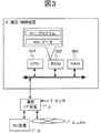
- the calculation / control device 6 attached to the outside of the machine tool 1 is obstructed by the operation of the machine tool. In that case, as shown in FIG. 3, it is possible to simplify the arithmetic / control device and store it in the accommodating portion of the control device of the machine tool 1.
- FIG. 3 shows a simplified configuration example of the arithmetic / control device of FIG.
- the symbols used are the same as in FIG.
- a program 611 and data 612 necessary for calculation / control are stored in a ROM and used.
- the display 607, mouse 608, keyboard 609, and printer 610 in FIG. 2 are omitted.
- a user interface or the like can be substituted by using an input / output device or a display device provided in the NC device 3.
- chatter vibration will be briefly described with reference to FIG. 4 and Table 1.
- FIG. 4 (a) shows an example in which the cutting tool forms a groove in the workpiece
- Table 1 shows an example of the processing conditions
- 4 (b) and 4 (c) are examples showing the change over time of the cutting force obtained by the processing of FIG. 4 (a).
- T is a rotary cutting tool and an end mill
- W is a workpiece
- an example is carbon steel for machine structure.
- the end mill T rotates in the direction of the arrow n and advances in the direction of the arrow f to process a groove having a depth ap in the carbon steel for mechanical structure W1.
- the machining conditions are as follows: tool diameter (D) is 40 mm, number of blades (NT) is two, rotation number (N) is 3120 min ⁇ 1 , one blade feed (fz) is 0.07 mm / It is a blade.
- FIG. 4C shows the result of measuring the time change of the cutting force generated in the direction of the arrow Y after the time has elapsed in the machining of FIG. 4B. In the measurement waveform G2, peaks and valleys with a short cycle are superimposed on peaks and valleys with a cutting cycle.
- chatter vibration occurs, and a waveform having a period extremely shorter than the cutting period is the chatter vibration waveform.
- chatter vibration is a vibration generated by a vibration having a period (high frequency) extremely shorter than the cutting period during the cutting process.
- chatter vibration short-period vibration that has reached an amplitude level that is harmful to cutting. It is customary. Performing the cutting process without generating the chatter vibration is important in designing the process conditions of the cutting process.
- FIG. 5A shows a result obtained by processing FFT of FIG. 4B, which is a cutting force waveform of machining in which chatter vibration is not generated.
- the spectrum has a significant peak at a cutting frequency (104 Hz) corresponding to the cutting cycle, and no significant peak occurs at a frequency higher than the cutting frequency.
- FIG.5 (b) is the result of having processed FIG.4 (c) which is the cutting force waveform of the process in which chatter vibration has generate
- the G4 region there is a waveform in which there is a significant peak at the cutting frequency (104 Hz), and a significant peak is also generated in the G5 region in the higher frequency band.
- the remarkable peak generated in the region of G5 represents the spectrum of the chatter vibration component.
- the inventor of the present application has found a phenomenon in which the vibration amplitude of a cutting tool that increases due to chatter vibration is proportional to the ratio of the maximum value of the cutting force component and the maximum value of the chatter vibration component. Therefore, a chatter index CVI (Chatter Vibratin Index) is defined as the following formula 1 as a judgment index of chatter vibration.
- CVI fb / fa (Equation 1) If a threshold value is set for this CVI, it is possible to determine whether chatter vibration has occurred or not with a constant.
- chatter index CVI
- FIG. 6 (a) is an example in which chatter vibration is generated with a cutting force waveform obtained by the same processing method as in FIG. 4 (a).
- FIG. 4 (a) shows an example of grooving performed using the full width of the tool, but
- FIG. 6 (a) shows a so-called shoulder cutting in which the side surface of the workpiece is cut by the radius of the tool. It is the waveform of the cutting force obtained by (1).
- FIG. 6B shows the result of performing FFT processing on this cutting force waveform, extracting only the chatter vibration component excluding the cutting force component, and separating it into the cutting force component and the chatter vibration component.
- the cutting force component shows a result in which a plurality of peaks occur at a frequency that is an integral multiple of the cutting frequency.
- the chatter vibration component there is a maximum peak at 620 Hz, and a peak is generated at 120 Hz.
- the peak frequency of the cutting force component closest to the frequency indicating the maximum peak of the chatter vibration component is searched, and the difference between the two is ⁇ .
- the peak of the cutting force component near 620 Hz is 635 Hz.
- Equation 2 ⁇ N 60 / NT (Formula 2)
- ⁇ N the number of rotations that increases or decreases from the current tool rotation number.
- the right side ⁇ is the frequency difference
- NT the number of cutting edges of the tool.
- the higher order frequency of the cutting force component is 15 Hz higher than the chatter vibration frequency.
- the primary frequency of the cutting force component is multiplied by an integer, and the frequency of the chatter vibration is the highest.
- a close frequency may be set as a high-order frequency of the cutting force for obtaining ⁇ .
- the rotation speed of the cutting tool is changed.
- increasing the speed of the tool may result in a choice that the cutting speed falls within the abnormal wear area of the tool.
- ⁇ is obtained by the above equation 2
- the tool rotational speed is forcibly decelerated using a frequency that is first order smaller than the higher order frequency of the optimum cutting force component, Becomes extremely low rotation and significantly impedes machining efficiency.
- FIG. 7A is a stability limit diagram, which is an unstable region in which chatter vibration is generated under a machining condition having a larger cut amount than the curve G6 called a lobe, and chatter vibration is generated under a condition in which the cut is smaller than the curve G6.
- a curve G6 is a curve obtained by calculation from the processing conditions shown in Table 1. Chatter vibration occurs in P1 where the cutting amount is 0.4 mm under the processing conditions shown in Table 1, but no chatter vibration occurs in the stable region when the cutting amount is 0.25 mm.
- FIG. 7B shows a state where the end mill T is machining the workpiece W, and the symbols used are the same as those in FIG. 4A.
- CVI chatter index
- chatter index CVI
- chatter vibration can be quickly suppressed even when means for reducing the cutting depth ap is adopted.
- S1 based on the data 612 of the calculation / control device 6, the tool used by the program 611, the tool trajectory, and the tool machining conditions are set.
- the data 611 includes information such as the shape of the work material before processing, the shape of the work material (product) after processing, and the shape of the tool 1 used for processing.
- the program also includes a function for setting a tool to be used, a tool trajectory, and a tool machining condition based on the data 611.
- the tool to be used, the tool trajectory, and the tool machining conditions may be set manually by using the input function of the calculation / control device 6 or the NC device 3.
- a program for driving the NC device 3 is created and sent to the NC device 3.
- the frequency being processed is measured.
- the measurement means is a sensor that can convert vibrations such as a force sensor, an acceleration sensor, a displacement sensor, and a sound sensor into signals.
- the vibration during processing is converted into a signal by any one of these sensors or a plurality of sensors and sent to the arithmetic / control device via the communication I / F 5.
- the program 611 performs frequency conversion on the signal sent in S2.
- the power spectrum is obtained by FFT.
- S4 the program 611 separates the cutting frequency and the chatter vibration frequency to obtain the magnitude of the cutting vibration and the magnitude of the chatter vibration.
- S5 the above-described chatter index (CVI) is obtained using FIG. 5 and Formula 1 (S6). It is determined whether chatter vibration is occurring. If it is determined that there is no chatter vibration, steps S2 to S5 are repeatedly executed to continue monitoring the machining state. If it is determined that chatter vibration has occurred, the process proceeds to S7 and S8.
- S7 the program 611 calculates the cutting frequency. From the primary cutting frequency, a high-order frequency until the chatter vibration frequency is exceeded is calculated.
- the program 611 calculates the chatter vibration frequency. In the FFT processing, the peak frequency that appears in the high frequency band is determined from the cutting frequency. (S9) In S9, the phase difference ⁇ described with reference to FIG. 6 is obtained from the result obtained by the program 611 in S7 and S8. (S10) In S10, the program 611 calculates the increase / decrease rotational speed ⁇ N of the tool according to Equation 2.
- This ⁇ N is added to or subtracted from the tool rotational speed at that time to calculate the corrected tool rotational speed.
- S11 it is determined whether or not the tool rotation speed obtained in S10 gives the cutting speed causing abnormal wear stored in the data 612 to the tool. If it is evaluated that the corrected tool rotational speed is appropriate, the corrected rotational speed is sent to the NC device 3 via the communication I / F 5 to change the tool rotational speed. If it is evaluated that the corrected tool rotational speed is inappropriate, the process proceeds to S12 without changing the tool rotational speed.
- the program 611 gives a command to reduce the cutting amount to the NC device 3 via the communication I / F 5.
- This command is continued until it is determined that there is no chatter vibration in S1 to S5 monitoring the machining state.
- the cutting amount reduction command is stopped, the program 611 calculates a subsequent tool path based on the reduced cutting amount, and sends the path program to the NC device 3 via the communication I / F 5.
- the present invention has industrial applicability with respect to a method for suppressing vibration generated by cutting, an arithmetic and control unit having the function, and a machine tool.
Abstract
L'invention concerne un procédé dans lequel des vibrations produites au cours d'un procédé de coupe sont analysées au moyen d'un indice de broutage, ledit indice de broutage étant le rapport entre la valeur maximale d'une composante de force de coupe et la valeur maximale d'une composante de vibration de broutage, et s'il est déterminé qu'une vibration de broutage est présente, un état d'usinage est corrigé. Une fréquence de coupe, ses harmoniques, une fréquence de broutage, et ses harmoniques sont calculées à partir d'une fréquence d'usinage ; une vitesse d'arbre rotatif qui réduit la différence de phase entre la fréquence de coupe et la fréquence de broutage est calculée ; et les conditions de coupe sont changées en fonction des résultats dudit calcul.
Applications Claiming Priority (2)
| Application Number | Priority Date | Filing Date | Title |
|---|---|---|---|
| JP2013009745A JP2014140918A (ja) | 2013-01-23 | 2013-01-23 | 切削振動抑止方法、演算制御装置、および工作機械 |
| JP2013-009745 | 2013-01-23 |
Publications (1)
| Publication Number | Publication Date |
|---|---|
| WO2014115395A1 true WO2014115395A1 (fr) | 2014-07-31 |
Family
ID=51227199
Family Applications (1)
| Application Number | Title | Priority Date | Filing Date |
|---|---|---|---|
| PCT/JP2013/079811 WO2014115395A1 (fr) | 2013-01-23 | 2013-11-05 | Procédé de suppression des vibrations de coupe, dispositif de commande de calcul, et machine-outil |
Country Status (2)
| Country | Link |
|---|---|
| JP (1) | JP2014140918A (fr) |
| WO (1) | WO2014115395A1 (fr) |
Cited By (4)
| Publication number | Priority date | Publication date | Assignee | Title |
|---|---|---|---|---|
| DE102016011402A1 (de) | 2015-09-29 | 2017-03-30 | Fanuc Corporation | Maschinelles Lernverfahren und maschinelle Lernvorrichtung zum Einlernen von Betriebsbefehlen für einen Elektromotor und Werkzeugmaschine mit maschineller Lernvorrichtung |
| JP6605185B1 (ja) * | 2019-04-08 | 2019-11-13 | 三菱電機株式会社 | 数値制御装置およびびびり振動の発生判定方法 |
| TWI733388B (zh) * | 2019-04-17 | 2021-07-11 | 日商歐姆龍股份有限公司 | 切削工具的磨損檢測方法以及切削加工裝置 |
| US11822317B2 (en) * | 2018-11-05 | 2023-11-21 | Siemens Aktiengesellschaft | Operator-defined avoidance of chatter |
Families Citing this family (10)
| Publication number | Priority date | Publication date | Assignee | Title |
|---|---|---|---|---|
| JP6257481B2 (ja) * | 2014-09-02 | 2018-01-10 | 三菱電機株式会社 | 数値制御装置 |
| KR101676538B1 (ko) * | 2014-11-25 | 2016-11-15 | 현대위아 주식회사 | 표면 거칠기 분석 장치 및 분석방법 |
| JP6575814B2 (ja) * | 2015-10-20 | 2019-09-18 | エヌティーエンジニアリング株式会社 | 作業機械の加工状態監視方法及びシステム |
| WO2018179368A1 (fr) * | 2017-03-31 | 2018-10-04 | 三菱電機株式会社 | Dispositif de commande et système de commande de moteur |
| JP6953545B2 (ja) * | 2017-10-25 | 2021-10-27 | 三菱重工業株式会社 | エンドミル仕様設定方法、加工条件設定方法および加工方法 |
| JP7084242B2 (ja) * | 2018-07-30 | 2022-06-14 | Dmg森精機株式会社 | 工具刃数推定装置およびこれを備えた工作機械、ならびに工具刃数推定方法 |
| JP6940474B2 (ja) | 2018-12-05 | 2021-09-29 | ファナック株式会社 | 工作機械 |
| JP7399661B2 (ja) | 2019-09-24 | 2023-12-18 | シチズン時計株式会社 | 加工装置、加工方法、及び加工システム |
| JP6944102B2 (ja) * | 2019-10-18 | 2021-10-06 | エヌティーエンジニアリング株式会社 | 作業機械の加工状態監視方法及びシステム |
| JP7179198B1 (ja) * | 2021-04-26 | 2022-11-28 | 三菱電機株式会社 | 数値制御装置、学習装置及び、びびり振動の抑制方法 |
Citations (11)
| Publication number | Priority date | Publication date | Assignee | Title |
|---|---|---|---|---|
| JPH068106A (ja) * | 1991-06-28 | 1994-01-18 | Mamoru Mitsuishi | 適応制御システムおよび状態判定装置 |
| JPH08229772A (ja) * | 1995-03-01 | 1996-09-10 | Toyota Motor Corp | 主軸回転数の設定方法および装置 |
| JP2000084798A (ja) * | 1998-09-10 | 2000-03-28 | Toshiba Corp | 加工異常検出装置及び加工制御装置並びに加工異常検出方法 |
| JP2008290186A (ja) * | 2007-05-24 | 2008-12-04 | Okuma Corp | 工作機械の振動抑制装置 |
| JP2009101495A (ja) * | 2007-10-25 | 2009-05-14 | Okuma Corp | 振動抑制装置 |
| JP2012056051A (ja) * | 2010-09-10 | 2012-03-22 | Makino Milling Mach Co Ltd | びびり振動検出方法及びびびり振動回避方法、並びに工作機械 |
| JP2012206230A (ja) * | 2011-03-30 | 2012-10-25 | Brother Industries Ltd | 加工びびり振動検出装置、及び工作機械 |
| WO2013073436A1 (fr) * | 2011-11-15 | 2013-05-23 | 株式会社日立製作所 | Dispositif de détection de force de coupe pour machine-outil, procédé de détection de force de coupe, procédé de détection d'anomalie de travail, et système de commande de condition de travail |
| WO2013088849A1 (fr) * | 2011-12-16 | 2013-06-20 | 株式会社日立製作所 | Dispositif de coupe et procédé de traitement utilisant celui-ci |
| JP5288318B1 (ja) * | 2012-10-23 | 2013-09-11 | エヌティーエンジニアリング株式会社 | 作業機械のびびり抑制方法 |
| JP2013215809A (ja) * | 2012-04-04 | 2013-10-24 | Hitachi Ltd | 切削加工システム及び方法 |
-
2013
- 2013-01-23 JP JP2013009745A patent/JP2014140918A/ja active Pending
- 2013-11-05 WO PCT/JP2013/079811 patent/WO2014115395A1/fr active Application Filing
Patent Citations (11)
| Publication number | Priority date | Publication date | Assignee | Title |
|---|---|---|---|---|
| JPH068106A (ja) * | 1991-06-28 | 1994-01-18 | Mamoru Mitsuishi | 適応制御システムおよび状態判定装置 |
| JPH08229772A (ja) * | 1995-03-01 | 1996-09-10 | Toyota Motor Corp | 主軸回転数の設定方法および装置 |
| JP2000084798A (ja) * | 1998-09-10 | 2000-03-28 | Toshiba Corp | 加工異常検出装置及び加工制御装置並びに加工異常検出方法 |
| JP2008290186A (ja) * | 2007-05-24 | 2008-12-04 | Okuma Corp | 工作機械の振動抑制装置 |
| JP2009101495A (ja) * | 2007-10-25 | 2009-05-14 | Okuma Corp | 振動抑制装置 |
| JP2012056051A (ja) * | 2010-09-10 | 2012-03-22 | Makino Milling Mach Co Ltd | びびり振動検出方法及びびびり振動回避方法、並びに工作機械 |
| JP2012206230A (ja) * | 2011-03-30 | 2012-10-25 | Brother Industries Ltd | 加工びびり振動検出装置、及び工作機械 |
| WO2013073436A1 (fr) * | 2011-11-15 | 2013-05-23 | 株式会社日立製作所 | Dispositif de détection de force de coupe pour machine-outil, procédé de détection de force de coupe, procédé de détection d'anomalie de travail, et système de commande de condition de travail |
| WO2013088849A1 (fr) * | 2011-12-16 | 2013-06-20 | 株式会社日立製作所 | Dispositif de coupe et procédé de traitement utilisant celui-ci |
| JP2013215809A (ja) * | 2012-04-04 | 2013-10-24 | Hitachi Ltd | 切削加工システム及び方法 |
| JP5288318B1 (ja) * | 2012-10-23 | 2013-09-11 | エヌティーエンジニアリング株式会社 | 作業機械のびびり抑制方法 |
Cited By (8)
| Publication number | Priority date | Publication date | Assignee | Title |
|---|---|---|---|---|
| DE102016011402A1 (de) | 2015-09-29 | 2017-03-30 | Fanuc Corporation | Maschinelles Lernverfahren und maschinelle Lernvorrichtung zum Einlernen von Betriebsbefehlen für einen Elektromotor und Werkzeugmaschine mit maschineller Lernvorrichtung |
| US10082771B2 (en) | 2015-09-29 | 2018-09-25 | Fanuc Corporation | Machine learning method and machine learning apparatus learning operating command to electric motor and machine tool including machine learning apparatus |
| US11822317B2 (en) * | 2018-11-05 | 2023-11-21 | Siemens Aktiengesellschaft | Operator-defined avoidance of chatter |
| JP6605185B1 (ja) * | 2019-04-08 | 2019-11-13 | 三菱電機株式会社 | 数値制御装置およびびびり振動の発生判定方法 |
| WO2020208893A1 (fr) * | 2019-04-08 | 2020-10-15 | 三菱電機株式会社 | Dispositif de commande numérique et dispositif d'apprentissage |
| WO2020208685A1 (fr) * | 2019-04-08 | 2020-10-15 | 三菱電機株式会社 | Dispositif de commande numérique et procédé d'identification de broutement |
| JPWO2020208893A1 (ja) * | 2019-04-08 | 2021-04-30 | 三菱電機株式会社 | 数値制御装置および学習装置 |
| TWI733388B (zh) * | 2019-04-17 | 2021-07-11 | 日商歐姆龍股份有限公司 | 切削工具的磨損檢測方法以及切削加工裝置 |
Also Published As
| Publication number | Publication date |
|---|---|
| JP2014140918A (ja) | 2014-08-07 |
Similar Documents
| Publication | Publication Date | Title |
|---|---|---|
| WO2014115395A1 (fr) | Procédé de suppression des vibrations de coupe, dispositif de commande de calcul, et machine-outil | |
| JP5686760B2 (ja) | 振動判別方法、及び振動判別装置 | |
| JP4582660B2 (ja) | 工作機械の振動抑制装置 | |
| US9138848B2 (en) | Method and apparatus for suppressing vibration | |
| JP5710391B2 (ja) | 工作機械の加工異常検知装置及び加工異常検知方法 | |
| US9211624B2 (en) | Vibration determination method and vibration determination device | |
| JP5234772B2 (ja) | 工作機械の振動抑制方法及び装置 | |
| JP5160980B2 (ja) | 振動抑制方法及び装置 | |
| JP4777960B2 (ja) | 振動抑制装置 | |
| JP5215064B2 (ja) | 工作機械のびびり振動抑制方法及びその装置 | |
| JP4433422B2 (ja) | 振動抑制装置 | |
| JP5622626B2 (ja) | 回転速度表示装置 | |
| JP6257481B2 (ja) | 数値制御装置 | |
| JP4891150B2 (ja) | 工作機械の振動抑制装置 | |
| JP5226484B2 (ja) | びびり振動抑制方法 | |
| JP4582661B2 (ja) | 工作機械の振動抑制装置 | |
| JP6302794B2 (ja) | 回転速度表示方法 | |
| JP5155090B2 (ja) | 工作機械の振動判定方法及び振動抑制装置 | |
| JP7109318B2 (ja) | 工作機械および工具異常判定方法 | |
| JP5660850B2 (ja) | 振動表示装置 | |
| US20180209839A1 (en) | Method and detection system for detecting self-excited vibrations | |
| JP5587707B2 (ja) | 振動抑制装置 | |
| JP2693664B2 (ja) | エンドミル加工における加工状態判定装置 | |
| JP2021020260A (ja) | 工作機械の主軸回転数制御装置および制御方法 | |
| JP5631758B2 (ja) | 振動抑制装置 |
Legal Events
| Date | Code | Title | Description |
|---|---|---|---|
| 121 | Ep: the epo has been informed by wipo that ep was designated in this application |
Ref document number: 13872572 Country of ref document: EP Kind code of ref document: A1 |
|
| NENP | Non-entry into the national phase |
Ref country code: DE |
|
| 122 | Ep: pct application non-entry in european phase |
Ref document number: 13872572 Country of ref document: EP Kind code of ref document: A1 |