WO2014112142A1 - 車両 - Google Patents
車両 Download PDFInfo
- Publication number
- WO2014112142A1 WO2014112142A1 PCT/JP2013/069309 JP2013069309W WO2014112142A1 WO 2014112142 A1 WO2014112142 A1 WO 2014112142A1 JP 2013069309 W JP2013069309 W JP 2013069309W WO 2014112142 A1 WO2014112142 A1 WO 2014112142A1
- Authority
- WO
- WIPO (PCT)
- Prior art keywords
- engine
- vehicle
- brake
- state
- braking
- Prior art date
- Legal status (The legal status is an assumption and is not a legal conclusion. Google has not performed a legal analysis and makes no representation as to the accuracy of the status listed.)
- Ceased
Links
Images


Classifications
-
- F—MECHANICAL ENGINEERING; LIGHTING; HEATING; WEAPONS; BLASTING
- F02—COMBUSTION ENGINES; HOT-GAS OR COMBUSTION-PRODUCT ENGINE PLANTS
- F02N—STARTING OF COMBUSTION ENGINES; STARTING AIDS FOR SUCH ENGINES, NOT OTHERWISE PROVIDED FOR
- F02N11/00—Starting of engines by means of electric motors
- F02N11/08—Circuits specially adapted for starting of engines
- F02N11/0814—Circuits specially adapted for starting of engines comprising means for controlling automatic idle-start-stop
- F02N11/0818—Conditions for starting or stopping the engine or for deactivating the idle-start-stop mode
- F02N11/0822—Conditions for starting or stopping the engine or for deactivating the idle-start-stop mode related to action of the driver
-
- Y—GENERAL TAGGING OF NEW TECHNOLOGICAL DEVELOPMENTS; GENERAL TAGGING OF CROSS-SECTIONAL TECHNOLOGIES SPANNING OVER SEVERAL SECTIONS OF THE IPC; TECHNICAL SUBJECTS COVERED BY FORMER USPC CROSS-REFERENCE ART COLLECTIONS [XRACs] AND DIGESTS
- Y02—TECHNOLOGIES OR APPLICATIONS FOR MITIGATION OR ADAPTATION AGAINST CLIMATE CHANGE
- Y02T—CLIMATE CHANGE MITIGATION TECHNOLOGIES RELATED TO TRANSPORTATION
- Y02T10/00—Road transport of goods or passengers
- Y02T10/10—Internal combustion engine [ICE] based vehicles
- Y02T10/40—Engine management systems
Definitions
- the present invention relates to a vehicle having a brake operation unit operated by a passenger's hand and using an engine as a power source.
- Patent Document 1 discloses an engine starter that starts an engine by rotating a starter when a main switch is switched to a start position when a brake lever is operated and a brake switch is turned on.
- the present invention provides a vehicle that can start an engine quickly without requiring a dedicated operation unit, thereby enabling a smooth start.
- One embodiment of the present invention is a vehicle that uses an engine as a power source, and is operated by a main switch for energizing an electrical system and a hand of an occupant for braking operation and braking release of the vehicle.
- the brake operation detection means that detects the operation of the brake operation unit, and the main switch is conducted and the electrical system is energized
- an engine control means for starting the engine in response to a change from a state in which the brake operation detecting means has not detected the braking operation to a state in which the braking operation is detected.
- the engine when the occupant performs a braking operation on the brake operation unit while the main switch is conducting and the engine is stopped, the engine is started. Therefore, since it is not necessary to perform another operation while performing the braking operation, the procedure for starting the engine is shortened and the engine can be started quickly.
- the engine can be started by a braking operation that is a necessary operation during normal driving, the driver can start the engine with the posture during driving. Therefore, the vehicle can be started immediately after the engine is started. Thus, it is possible to provide a vehicle that can start the engine quickly and start smoothly.
- the engine can be started without requiring a dedicated operation unit such as a starter switch.
- the electrical system is a vehicle equipment that operates with power supplied from a power source (battery) mounted on the vehicle.
- the engine control means includes an idle stop control means for stopping (automatically stopping) the engine and setting the engine to an idle stop state when an idle stop condition is satisfied while the engine is operating.
- Restart control means for restarting the engine in response to the brake operation detection means detecting the braking operation when the engine is in an idle stop state.
- the idle stop state is a state in which the engine is automatically stopped by the operation of the idle stop control means. The restart is to start an engine in an idle stop state.
- the engine can be restarted from the idle stop state by a braking operation. Accordingly, the engine can be restarted quickly and the vehicle can be started smoothly. If both the engine start from the normal stop state and the engine restart from the idle stop state can be performed by the braking operation of the brake operation unit, the operation for starting the engine (including restart) can be performed. Easy to understand.
- the normal stop state is a stop state other than the idle stop state. Specifically, the state from when the main switch is turned on until the engine is started, the state where the engine is stopped due to the engine stall, and the like are applicable.
- Patent Document 2 discloses an engine stop / start control device that restarts the engine when an accelerator operation is detected during idle stop.
- the accelerator when the accelerator is operated, the starter motor rotates in response thereto and the engine is started. Then, the engine rotation speed is increased, the centrifugal clutch is connected, the driving force is transmitted to the wheels, and the vehicle starts. Therefore, the delay time from the accelerator operation to the completion of the series of operations is relatively long, and a feeling of stagnation at the start of the vehicle occurs.
- the throttle opens in response to the accelerator operation, complicated engine restart control is required to prevent sudden start due to engine blow-up.
- Patent Document 3 discloses an engine control device that restarts the engine in response to a brake release operation in an idle stop state.
- this configuration may be inconvenient in a vehicle in which the brake operation unit is operated by a passenger's hand. Specifically, the engine is restarted when the vehicle is stopped by waiting for a signal or the like, and when the brake is released by releasing the hand from the brake operation unit in an idle stop state accordingly. Therefore, if an attempt is made to maintain the idle stop state, the driver cannot be released from the brake operation unit, so that the driver's freedom is limited.
- the engine restarts in response to the braking operation, so that the above problem is solved. That is, since the engine can be restarted by the braking operation, the driver can restart the engine in advance as necessary before performing the accelerator operation. As a result, the delay time from the accelerator operation to the start of the vehicle is shortened, so that a smooth start is possible. Moreover, since the braking operation, not the accelerator operation, is an opportunity for engine restart, complicated control based on the assumption that the throttle is opened at the time of engine restart is not necessary. Thereby, the control content at the time of engine restart can be simplified.
- the engine does not restart carelessly due to accelerator operation, and special components such as seating sensors may be required for engine restart control. Absent. Further, since the engine is restarted not by the braking release operation but by the braking operation, the engine will not restart even if the brake operation unit is released after the idling stop. Therefore, the driver can release his / her hand from the brake operation unit as necessary while avoiding restart of the engine, and thus the degree of freedom of the driver can be increased without impairing energy saving performance. Moreover, since the engine is started in a state where the vehicle is braked, the vehicle will not start carelessly.
- the idling stop condition includes that the brake operation detecting means detects the braking operation, and the restart control means is preset in advance after the engine is in the idling stop state. If the brake operation detecting means continues to detect the braking operation even after a predetermined determination time has elapsed, the brake operation detecting means subsequently changes to a state in which the release operation is detected. Restart the engine.
- the braking operation is a necessary condition for idling stop. Therefore, when the engine stops idling, a braking operation is performed. If the braking operation continues beyond the predetermined determination time even after the idling stop, it can be estimated that the driver's intention is the start of the vehicle when the braking operation is released next time. Therefore, when the braking operation is continued beyond the predetermined determination time even after the idling stop, the engine is restarted in response to the next release operation. Thus, the intention of the driver can be estimated and the engine can be restarted appropriately. Even if the braking operation is released within the determination time after the idling stop, the engine does not restart. Therefore, the driver can release his hand from the brake operation unit (braking release) as necessary after the idling stop. Therefore, it is possible to provide a vehicle that does not impair the convenience of the driver while making the braking operation a necessary condition for stopping the idle.
- the restart control means when the brake operation detecting means does not detect the braking operation within the determination time after the engine is in an idle stop state, The engine is restarted in response to the change to the state in which the brake operation detecting means detects the braking operation.
- the engine when the braking operation is continuously detected after the determination time after the idle stop, the engine is restarted in response to the subsequent release operation, while the braking operation is performed within the determination time. If released, the engine is restarted in response to the subsequent braking operation. That is, the trigger for engine restart is switched between the release operation and the brake operation depending on whether or not the time from the idle stop to the brake release exceeds the determination time. If the braking operation is continued beyond the determination time after the idling stop, it can be estimated that the driver's intention is the start of the vehicle when the release operation is performed next. For example, this situation occurs when the vehicle is stopped on a slope or when the driver continues the braking operation for peace of mind even when the vehicle stops on a flat ground.
- the engine restart can be controlled by appropriately estimating the driver's intention by switching the trigger for restarting the engine according to the duration of the braking operation from the idle stop. Even if the release operation performed within the determination time from the idle stop is an operation intended to prepare for starting the vehicle, the driver can start the engine quickly by performing the braking operation.
- One embodiment of the present invention further includes vehicle speed detection means for detecting the speed of the vehicle, and the restart control means determines whether or not the vehicle is stopped based on an output signal of the vehicle speed detection means. And a requirement for restarting the engine that the vehicle is stopped.
- One embodiment of the present invention further includes throttle opening detection means for detecting the throttle opening of the engine, wherein the restart control means is equal to or less than a restart permission opening predetermined by the throttle opening detection means (for example, The detection of "full throttle closure” is a necessary condition for restarting the engine.
- the throttle opening (less than the restart permission opening when the engine is restarted) ( For example, fully closed). This facilitates control for restarting the engine.
- the brake operation unit is provided on a handle for steering the vehicle. According to this structure, an engine can be started by operation of the brake operation part provided in the steering wheel for steering of a vehicle. Accordingly, there is no need to arrange a dedicated operation part for starting the engine in the vicinity of the handle, so that a space for arranging switches in the vicinity of the handle can be afforded.
- One embodiment of the present invention further includes an accelerator grip that is attached to the handle and is operated by an occupant to adjust the output of the engine by grasping with one of the left and right hands, and the brake operation unit includes the accelerator grip.
- the accelerator grip Includes a brake lever that is gripped and operated.
- the accelerator grip may be a right grip or a left grip.
- the vehicle is braked when the brake lever is grasped together with the accelerator grip, and the braking can be released when the grasping force is loosened.
- the accelerator grip can be rotated with respect to the handle, for example, so that the engine output increases when rotating toward the driver's front side, and the engine output decreases when rotating toward the opposite side. It may be configured.
- the engine output is minimized (specifically, the throttle is fully closed) by grasping the brake lever. Therefore, when the engine is started by performing a braking operation for gripping the brake lever, the engine output can be minimized (throttle fully closed), so that the control at the time of engine start is simplified.
- a vehicle according to an embodiment of the present invention is a saddle-ride type vehicle having a saddle type seat on which an occupant sits straddling. According to this configuration, the engine can be started quickly by a braking operation, and a saddle-ride type vehicle that realizes a smooth start can be provided.
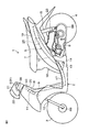
- FIG. 1 is an illustrative side view for explaining the configuration of a saddle-ride type vehicle according to an embodiment of the present invention.
- FIG. 2 is a perspective view showing a configuration example of a handle of the saddle riding type vehicle, and shows a configuration looking down from a driver seated on a seat of the saddle riding type vehicle.
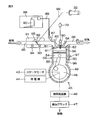
- FIG. 3 is a schematic diagram for explaining a configuration related to the engine of the saddle riding type vehicle.
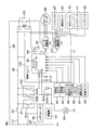
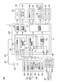
- FIG. 4 is a block diagram for explaining an electrical configuration of a main part related to the control of the engine.
- FIG. 5 is a block diagram for explaining a functional configuration of a microcomputer for controlling the engine.
- FIG. 1 is an illustrative side view for explaining the configuration of a saddle-ride type vehicle according to an embodiment of the present invention.
- FIG. 2 is a perspective view showing a configuration example of a handle of the saddle riding type vehicle, and shows a configuration looking down from a driver seated on a seat of the saddle riding type vehicle.
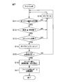
- FIG. 6 is a flowchart for explaining the flow from the start of the engine to the transition to the idle state, and shows the processing contents when the operating state of the engine is “normally stopped”.
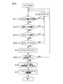
- FIG. 7 is a flowchart for explaining the control contents of the microcomputer when the state of the engine is “idling”.
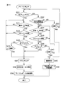
- FIG. 8 is a flowchart showing a control operation executed by the microcomputer when the engine is in an idle stop state.
- FIG. 9 is a state transition diagram for explaining the transition of the operating state of the engine.
- FIG. 10 is a view for explaining the configuration of a saddle-ride type vehicle (motorcycle) according to the second embodiment of the present invention, and is a flowchart showing an engine control operation during idling.
- FIG. 11 is a flowchart showing an engine control operation during idling stop in the second embodiment.
- FIG. 1 is a schematic side view for explaining the configuration of a saddle riding type vehicle according to an embodiment of the present invention.
- FIG. 1 shows a scooter type motorcycle 1 which is an example of a saddle type vehicle.
- the front, rear, left, right, and up and down directions of the motorcycle 1 are represented based on the viewpoint of the rider (driver, occupant) who has entered the motorcycle 1.
- the motorcycle 1 includes a vehicle main body 2, a front wheel 3, and a rear wheel 4.
- the vehicle body 2 includes a body frame 5, a handle 6, a saddle-shaped seat 7, and a power unit 8.
- the vehicle body frame 5 includes a down tube 9 disposed in front and a pair of left and right side frames 10 disposed behind the down tube 9.
- the down tube 9 extends obliquely upward toward the front, and a head pipe 11 is fixed to an upper end portion thereof.
- a steering shaft 20 is rotatably supported on the head pipe 11.
- a pair of left and right front forks 12 are fixed to the lower end of the steering shaft 20.
- a handle 6 is attached to the upper end portion of the steering shaft 20, and the front wheel 3 is rotatably attached to the lower end portion of the front fork 12.
- a front wheel brake unit 69 for braking the front wheel 3 is attached to the lower end of the front fork 12.
- the side frame 10 is curved so as to form an S shape, and extends obliquely upward from the lower end of the down tube 9 toward the rear.
- a seat 7 is supported on the side frame 10. The seat 7 is configured such that an occupant sits across the seat.
- a bracket 13 is fixed to an intermediate portion of the side frame 10.
- a power unit 8 is supported on the bracket 13 via a pivot shaft 14 so as to be swingable in the vertical direction.
- the power unit 8 is a unit swing type engine unit. Above the power unit 8, an air cleaner 23 for cleaning the air taken into the engine is disposed.
- a cushion unit 15 is bridged between the rear end portion of the side frame 10 and the rear end portion of the power unit 8.
- the rear wheel 4 is rotatably supported at the rear end portion of the power unit 8.
- a rear wheel brake unit 68 for braking the rear wheel 4 is further attached to the rear end portion of the power unit 8.
- the body frame 5 is covered with a resin body cover 16.
- the vehicle body cover 16 is provided on the lower front side of the seat 7 to provide a footrest portion, a front cover 18 that covers the head pipe 11, a side cover 19 that covers an area below the seat 7, and a handle. 6 and a handle cover 21 covering 6.
- a battery 25 is accommodated in a space covered by the side cover 19 below the seat 7 and supported by the vehicle body frame 5.
- a headlamp 22 is provided so as to be exposed forward from the handle cover 21 and is supported by the handle 6.
- the main switch 40 for energizing the electric power stored in the battery 25 to the electrical system of the motorcycle 1 is disposed, for example, on the rear surface of the front cover 18 (surface facing the seat 7).
- the main switch 40 may be a key switch operated by using a key held by the user.
- the electrical system is equipment that operates by receiving power supply from the battery 25 among the equipment of the motorcycle 1.
- the power unit 8 includes, for example, a starter motor, a generator, an engine, a continuously variable transmission, and a centrifugal clutch.
- the starter motor is operated by electric power from the battery 25 and rotates the crankshaft of the engine when the engine is started.
- the generator is coupled to the crankshaft of the engine and generates electric power by the rotational force of the crankshaft.
- the battery 25 is charged with the electric power.
- the starter motor and the generator may be integrated.
- One rotating electric machine may have both functions of a starter motor and a generator.
- the continuously variable transmission is a mechanism that continuously changes the ratio between the rotational speed of the engine and the rotational speed of the rear wheel 4 as a drive wheel in accordance with the rotational speed of the engine.
- the centrifugal clutch is a clutch mechanism that switches between a connected state and a disconnected state according to the engine speed. Specifically, when the engine rotation speed is less than the connection speed, the centrifugal clutch is in a cut-off state in which the driving force transmission path between the engine and the rear wheel 4 is cut off. When the engine rotation speed reaches the connection speed, the connection state is established in which the driving force of the engine is transmitted to the rear wheels 4.
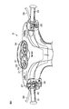
- FIG. 2 is a perspective view showing an example of the configuration of the handle 6 and shows the configuration viewed from the driver seated on the seat 7.
- the handle 6 includes a handle bar 30 extending left and right, and grips 31 and 32 provided at the left end and the right end of the handle bar 30, respectively.
- a left brake lever 38 for operating a rear wheel brake unit 68 (see FIG. 1) is disposed in front of the left grip 31, and a front wheel brake unit 69 (see FIG. 1) is operated in front of the right grip 32.
- a right brake lever 39 is provided for this purpose.
- the left brake lever 38 is a brake operation unit that the driver grips and operates with the left grip 31 with the left hand, the gripping operation is a braking operation that activates the rear wheel brake unit 68, and the operation that releases the grip is the rear wheel brake. This is a release operation for releasing the braking of the unit 68.
- the right brake lever 39 is a brake operation unit that is operated by the driver gripping with the right grip 32 with the right hand, the gripping operation is a braking operation that operates the front wheel brake unit 69, and the operation of releasing the grip is the front wheel. This is a release operation for releasing the braking of the brake unit 69.
- the right grip 32 is attached so as to be rotatable within a predetermined angle range around the axis of the handle bar 30 and is an accelerator grip for operating the accelerator.
- the accelerator grip 32 rotates to the front side of the driver (the seat 7 side, the output increasing direction)
- the engine output specifically, the throttle opening
- the engine output is configured to decrease. Therefore, when a braking operation for gripping the right brake lever 39 is performed, the accelerator grip 32 naturally rotates to the side opposite to the seat 7 (output decreasing direction), and the engine output is minimized (specifically, the throttle is fully closed). Become.
- the handle bar 30 is covered with a handle cover 21.
- the handle cover 21 is provided with a speedometer 33 and an engine speed meter 34.
- Indicators 41 and 42 are arranged on the speedometer 33.
- the indicator 41 is lit when the engine 45 is automatically stopped by the idle stop control described later and shifts to the idle stop state.
- the indicator 42 is a warning light that is turned on when a failure occurs in the brake switch unit 62 (see FIG. 4) for detecting the operation of the right brake lever 39.
- an idle stop cancel button 35 for switching between enabling / disabling of an idle stop function described later is disposed.
- a blinker switch 36, a headlight switch 37, and the like are disposed in the vicinity of the left grip 31.
- FIG. 3 is a schematic diagram for explaining a configuration related to the engine provided in the power unit 8.
- the engine 45 includes a crankshaft 48, a crankcase 49 that houses the crankshaft 48, a cylinder block 50 that extends from the crankcase 49, and a cylinder head 51 that is fixed to the tip of the cylinder block 50.
- the cylinder block 50 and the cylinder head 51 constitute a cylinder 53.
- a piston 54 is slidably accommodated in the cylinder block 50.
- the piston 54 and the crankshaft 48 are connected by a connecting rod 55.
- a combustion chamber 56 is defined by the cylinder block 50, the cylinder head 51, and the piston 54.
- a starter motor 43 and a generator 44 are coupled to the crankshaft 48.
- the rotation of the crankshaft 48 is transmitted to the rear wheel 4 via the continuously variable transmission 46 and the centrifugal clutch 47.
- An intake port 81 and an exhaust port 82 that face the combustion chamber 56 are formed in the cylinder head 51.
- a spark plug 80 is disposed on the cylinder head 51 so as to face the combustion chamber 56.
- An ignition coil 79 is connected to the spark plug 80. When the energy stored in the ignition coil 79 is supplied to the spark plug 80, the spark plug 80 causes a spark discharge in the combustion chamber 56.
- An intake valve 83 is disposed at the intake port 81, and an exhaust valve 84 is disposed at the exhaust port 82.
- the intake valve 83 opens and closes the intake port 81, and the exhaust valve 84 opens and closes the exhaust port 82.
- the intake valve 83 and the exhaust valve 84 are driven by a valve gear (not shown) that works in conjunction with the crankshaft 48.
- the intake port 81 is connected to the intake port 85, and the exhaust port 82 is connected to the exhaust port 86.
- the engine 45 is a fuel injection type engine in this embodiment.
- the injector 87 is disposed upstream of the intake valve 83 in the intake port 85.
- the injector 87 is disposed so as to inject fuel toward the intake port 81.
- Fuel is supplied to the injector 87 from a fuel tank 88 through a fuel hose 89.
- a fuel pump 90 is disposed in the fuel tank 88. The fuel pump 90 pumps the fuel in the fuel tank 88 to the fuel hose 89.
- a throttle body 91 is disposed upstream of the injector 87 in the intake port 85.
- the throttle body 91 holds a throttle valve 92, an intake pressure sensor 93, an intake air temperature sensor 94, and a throttle opening degree sensor 95.
- the throttle valve 92 may be, for example, a butterfly valve including a plate-like valve body that is rotatably disposed in the intake port 85.
- the throttle valve 92 is mechanically coupled to the accelerator grip 32 via a wire 99. That is, when the accelerator grip 32 is operated, the throttle valve 92 is displaced (angular displacement in this embodiment) according to the operation direction and the operation amount, thereby changing the throttle opening.
- the position of the throttle valve 92 is detected by a throttle opening sensor 95.
- the throttle opening sensor 95 is throttle opening detection means for detecting the throttle opening. Further, since the throttle valve 92 and the accelerator grip 32 are mechanically connected, in this embodiment, the throttle opening sensor 95 also functions as an accelerator operation detecting means for detecting the accelerator opening as the accelerator command value. Will do.
- the accelerator opening is an operation amount of the accelerator grip 32.
- the intake pressure sensor 93 detects the pressure of the intake air.
- the intake air temperature sensor 94 detects the temperature of the intake air.
- a crank angle sensor 96 for detecting the rotation angle of the crankshaft 48 is attached to the crankcase 49.
- an engine temperature sensor 97 for detecting the temperature of the engine 45 is attached to the cylinder block 50.
- FIG. 4 is a block diagram for explaining an electrical configuration of a main part related to the control of the engine 45. Outputs of the sensors 93 to 97 are input to a control unit (ECU: electronic control unit) 100. A vehicle speed sensor 98 is further connected to the control unit 100. The vehicle speed sensor 98 is a sensor that detects the vehicle speed of the motorcycle 1 and may be a wheel speed sensor that detects the rotational speed of the wheels 3 and 4.
- the control unit 100 drives the fuel pump 90 and the injector 87 based on the output signals from the sensors 93 to 98 and the like, thereby controlling the fuel injection amount and the fuel injection timing.
- An ignition coil 79 is further connected to the control unit 100.
- the ignition coil 79 stores electric power for causing spark discharge of the spark plug 80.
- the control unit 100 controls energization to the ignition coil 79 based on output signals from the sensors 93 to 98 and the like, thereby controlling the ignition timing (discharge timing of the spark plug 80). Further, the control unit 100 controls energization to the starter motor 43, thereby controlling the start of the engine 45.
- the control unit 100 includes a microcomputer 60, a motor drive unit 59, a relay drive unit 58, and a drive unit 57 for other actuators.
- the motor drive unit 59 supplies power to the starter motor 43.
- the relay drive unit 58 opens and closes the relay 29 that controls power supply from the power supply line 28 to the motor drive unit 59.
- the drive unit 57 includes a drive circuit that supplies power to actuators such as the injector 87, the fuel pump 90, the ignition coil 79, and the indicators 41 and 42.
- the microcomputer 60 controls the motor drive unit 59, the relay drive unit 58, the drive unit 57, and the like based on output signals from the sensors 93 to 98 and the like.
- the battery 25 is connected to the power supply line 26 via the fuse 27 and the main switch 40.
- the battery 25 is connected to a relay 29 via a power supply line 28 that bypasses the fuse 27 and the main switch 40.
- the electric power stored in the battery 25 is supplied to the starter motor 43, the control unit 100, the ignition coil 79, the injector 87, the fuel pump 90, the indicators 41 and 42, etc. via the power supply lines 26 and 28. Therefore, these are all examples of electrical components.
- the electrical components include a headlamp 22, a tail lamp, a blinker lamp, and the like.
- the battery 25 is supplied with electric power generated by the generator 44 and rectified and adjusted by the regulator 78, whereby the battery 25 is charged during operation of the engine 45.
- a parallel circuit of a rear wheel brake switch unit 61 and a front wheel brake switch unit 62 is connected to the power supply line 26 on the side opposite to the battery 25 with respect to the main switch 40.
- a brake lamp 63 is connected in series to the parallel circuit of these brake switch units 61 and 62. Therefore, when any one of the brake switch units 61 and 62 is turned on, the brake lamp 63 is energized and lights up.
- the rear wheel brake switch unit 61 includes one brake switch 61A that is turned on when the left brake lever 38 is operated and is cut off when the left brake lever 38 is not operated.
- the front wheel brake switch unit 62 includes two brake switches 62A and 62B that are turned on when the right brake lever 39 is operated and are cut off when the right brake lever 39 is not operated.
- Diodes 64A and 64B are connected in series to the two brake switches 62A and 62B, respectively.
- a series circuit of the brake switch 62A and the diode 64A and a series circuit of the brake switch 62B and the diode 64B are connected in parallel between the power supply line 26 and the brake lamp 63.
- the brake lever 39 disposed corresponding to the accelerator grip 32 is an example of a brake operation unit.
- the brake switch unit 62 that detects the operation of the brake lever 39 is an example of a brake operation detection unit.
- the accelerator grip may be the right grip 32 or the left grip 31.
- the left brake lever 38 is an example of a brake operation unit
- the brake switch unit 61 that detects the operation is an example of a brake operation detection unit.
- the potential of the line between the brake switch 62A and the diode 64A is input to the port P1 of the microcomputer 60 as a front wheel brake operation signal.
- the potential of the line between the brake switch 62B and the diode 64B is input to the port P2 of the microcomputer 60 as a front wheel brake operation signal.
- the front wheel brake operation signal is turned on for a braking operation for gripping the right brake lever 39 and turned off for a release operation for releasing the right brake lever 39. That is, the front wheel brake operation signal is a signal representing a braking operation and a releasing operation with respect to the right brake lever 39.
- the microcomputer 60 controls the engine 45 based on the front wheel brake operation signal, and detects a failure of the brake switches 62A and 62B. For example, the microcomputer 60 compares two front wheel brake signals and determines that the brake switches 62A and 62B are normal if they match, and if they do not match, there is a failure in one of the brake switches 62A and 62B. Determine that it has occurred. When a failure has occurred, the microcomputer 60 turns on the indicator 42. The diodes 64A and 64B prevent the front wheel brake operation signal from wrapping around from one of the brake switches 62A and 62B to the other.
- control unit 100 is connected to the main switch 40 on the side opposite to the battery 25. That is, when the main switch 40 is turned on, power is supplied to the control unit 100 and a control operation by the control unit 100 is started.
- FIG. 5 is a block diagram for explaining a functional configuration of the microcomputer 60.
- the microcomputer 60 includes a CPU (Central Processing Unit) and a memory. When the CPU executes a program stored in the memory, each function of the function processing unit described below is realized.
- CPU Central Processing Unit
- the microcomputer 60 includes an engine control unit 70 as an engine control unit and a failure detection unit 73 as a failure detection unit as function processing units.
- the engine control unit 70 includes an idle stop control unit 71 as an idle stop control unit and an engine restart control unit 72 as a restart control unit.
- the engine control unit 70 responds to the fact that the braking operation of the right brake lever 39 is detected when the engine 45 is stopped when the main switch 40 is turned on and the electric system of the motorcycle 1 is energized. Then, the engine 45 is started. More specifically, the engine control unit 70 detects a braking operation on the right brake lever 39 based on a front wheel brake operation signal input to the ports P1 and P2. Further, the engine control unit 70 determines whether or not the engine 45 is stopped (stopped state) based on the output signal of the crank angle sensor 96. Then, when a braking operation is detected while the engine 45 is stopped, the engine control unit 70 controls the relay driving unit 58 to turn on the relay 29 and further controls the motor driving unit 59 in response thereto.
- the engine control unit 70 controls the fuel pump 90 and the injector 87 by controlling the drive unit 57 to start fuel injection control for controlling the fuel injection amount and the fuel injection timing.
- the engine control unit 70 also controls the drive unit 57 to control energization to the ignition coil 79 and start ignition control to control spark discharge of the spark plug 80.
- the engine 45 is started by starting cranking, fuel injection control and ignition control of the engine 45.
- the idle stop control unit 71 automatically stops the engine 45 and shifts to the idle stop state when a predetermined idle stop condition is satisfied while the engine 45 is in the idle state.
- the idle state is an operating state in which the throttle opening is fully closed and the engine rotational speed is a value within an idle rotational speed range (for example, 2500 rpm or less).
- the idle stop state refers to a state in which the operation of the engine 45 is automatically stopped by the control by the idle stop control unit 71. Specifically, the idle stop control unit 71 stops the fuel injection control and the ignition control, and thereby stops the engine 45.
- the engine restart control unit 72 restarts the engine 45 when the braking operation of the right brake lever 39 is detected while the engine 45 is in the idling stop state.
- the restart means that the engine 45 in an idle stop state is started.
- the engine restart control unit 72 controls the relay driving unit 58 to turn on the relay 29 and controls the motor driving unit 59 to operate the starter motor 43 and to switch the driving unit 57. Control to start fuel injection control and ignition control. As a result, the starter motor 43 is operated to perform cranking, fuel is injected from the injector 87, spark discharge of the spark plug 80 is caused, and the engine 45 is restarted.
- the failure detection unit 73 determines whether or not the brake switch unit 62 has failed based on front wheel brake operation signals input to the ports P1 and P2. For example, the failure detection unit 73 may determine that there is no failure if the front wheel brake operation signals input to the ports P1 and P2 match, and may determine that a failure has occurred if they do not match.
- the microcomputer 60 holds information related to the operating state of the engine 45 and executes control of contents according to the operating state. Specifically, the microcomputer 60 changes the operation state of the engine 45 to “normally stopped” (normally stopped state), “idle” (during operation), and “idle stopped” (idle stopped state). It is programmed to classify and control the start and stop of the engine 45 according to its operating state.
- the normal stop is a state from when the main switch 40 is turned on until the engine 45 is started.
- the idling state is a state in which the engine 45 is in operation, and not only the state in which the engine 45 is being operated at the idle rotational speed but also the state in which the engine 45 is being operated at a rotational speed exceeding the idle rotational speed is also “in idle”. Applicable. “During idle stop” means a state in which the operation of the engine 45 is automatically stopped under the control of the microcomputer 60 (idle stop state).
- FIG. 6 is a flowchart for explaining the flow from the start of the engine 45 to the transition to the idle state, and shows the processing contents when the operation state of the engine 45 is “normally stopped”.
- the microcomputer 60 (particularly the engine control unit 70) refers to the output signals of the crank angle sensor 96, the vehicle speed sensor 98, and the throttle opening sensor 95.
- the microcomputer 60 confirms that the engine 45 is stopped (step S1), the vehicle speed is zero (step S2), and the throttle is fully closed (step S3). If both of these are positively determined, the microcomputer 60 determines whether or not the right brake lever 39 has been braked (step S4).
- step S1 referring to the front wheel brake operation signals input to the ports P1 and P2, when detecting that the brake switch 62A or 62B has changed from OFF to ON, the microcomputer 60 causes the right brake lever 39 to brake. It is determined that it has been operated. If this determination is negative, the process returns to step S1.
- the determinations in steps S1 to S4 may be performed in any order, and two or more determinations may be performed simultaneously. Further, the determinations in steps S1 to S3 are not necessarily required, and the engine 45 may be started only on the condition that the determination in step S4 is affirmative.
- step S4 If it is determined in step S4 that the braking operation of the right brake lever 39 has been performed, the microcomputer 60 controls the relay driving unit 58 to turn on the relay 29, and further controls the motor driving unit 59 to start the motor. 43 is activated. Thereby, the crankshaft 48 is rotated by the starter motor 43, and cranking is performed (step S5). Further, the microcomputer 60 controls the drive unit 57 to operate the injector 87 and the fuel pump 90 to start fuel injection control, and starts ignition control by energization control to the ignition coil 79 (step S6). . As a result, the engine 45 is started, and the operating state transitions from “normally stopped” to “idling” (step S7). Specifically, the microcomputer 60 writes operating state information indicating “idling” in a built-in memory.
- FIG. 7 is a flowchart for explaining the control contents of the microcomputer 60 when the state of the engine 45 is “idling”.
- the microcomputer 60 determines whether the idle stop condition is satisfied. Therefore, the microcomputer 60 determines whether or not all of the next automatic stop conditions A1 to A3 are satisfied (steps S11 to S13).
- the determination regarding the automatic stop conditions A1 to A3 may be performed in any order, and two or more determinations may be performed simultaneously. One or two of the automatic stop conditions A1 to A3 may be omitted.
- Automatic stop condition A1 The engine temperature is equal to or higher than a predetermined value (for example, 60 ° C.). This condition is a condition for confirming that the engine 45 is sufficiently warm and can be easily restarted even if the operation is stopped.
- the microcomputer 60 makes a determination regarding the engine temperature based on the output signal of the engine temperature sensor 97.
- the vehicle speed is a predetermined value (for example, 3 km / h) or less.
- This condition is a condition for confirming that the motorcycle 1 is stopped. Specifically, the condition is that the vehicle speed sensor 98 detects a vehicle speed equal to or lower than a predetermined value.
- Automatic stop condition A3 The accelerator grip 32 is in the fully closed position. This condition is a condition for confirming that the driver does not intend to transmit the driving force of the engine 45 to the rear wheel 4 that is the driving wheel.
- the accelerator grip 32 and the throttle valve 92 are mechanically interlocked by the wire 99, if the throttle opening sensor 95 detects that the throttle valve 92 is fully closed, the accelerator grip 32 is fully closed. It will be in.
- the microcomputer 60 increments an internal timer (step S14), and the timer value is a predetermined value (for example, it is determined whether or not (a value corresponding to 3 seconds) has been reached (step S15).
- the timer measures the duration time in which all the automatic stop conditions A1 to A3 are satisfied.
- the microcomputer 60 resets the timer to zero (step S18).
- the microcomputer 60 determines that the idle stop condition is satisfied and shifts the engine 45 to the idle stop state (step S16). . That is, the microcomputer 60 controls the drive unit 57 to stop the fuel injection control and the ignition control, and automatically stops the engine 45. Then, the microcomputer 60 changes the operating state of the engine 45 from “idling” to “idling stopped” (step S17). Specifically, the microcomputer 60 writes operating state information indicating “idling stop” in a built-in memory.
- a predetermined value for example, a value corresponding to 3 seconds
- the idle stop condition is that a state in which all of the automatic stop conditions A1 to A3 are satisfied continues for a predetermined time.
- the microcomputer 60 turns on the indicator 41. This notifies the driver that the vehicle is idling.
- FIG. 8 is a flowchart showing a control operation executed by the microcomputer 60 when the engine 45 is in an idle stop state.
- the microcomputer 60 determines whether the vehicle speed is a predetermined value (for example, 3 km / h) or less with reference to the output signal of the vehicle speed sensor 98 (step S21), and refers to the output signal of the throttle opening sensor 95 to determine whether the throttle is It is determined whether it is fully closed (step S22). When any of these determinations is negative, the operation from step S21 is repeated. If the determinations in steps S21 and S22 are both positive, the microcomputer 60 further determines whether or not the braking operation of the right brake lever 39 has been performed (step S23).
- the microcomputer 60 determines whether or not the brake switch 62A or 62B has been turned on from off by referring to the previous brake operation signal input to the ports P1 and P2. When the microcomputer 60 changes from off to on, the right brake It is determined that the braking operation of the lever 39 has been performed. If this determination is affirmed, the microcomputer 60 executes control for restarting the engine 45. That is, the microcomputer 60 controls the relay driving unit 58 to close the relay 29 and controls the motor driving unit 59 to drive the starter motor 43. Thereby, cranking for rotating the crankshaft 48 of the engine 45 is performed (step S24). Further, the microcomputer 60 controls the drive unit 57 to start fuel injection control and ignition control (step S25). Thereby, the engine 45 is restarted.
- the microcomputer 60 changes the state information indicating the state of the engine 45 from “idle stop” to “idle” (step S26). Specifically, the microcomputer 60 writes operating state information indicating “idling” in a built-in memory. Therefore, the subsequent operation follows the flowchart of FIG.
- step S23 the microcomputer 60 further determines whether or not the brake switch unit 62 has failed based on the front wheel brake operation signals input to the ports P1 and P2 (step S27). ). That is, it is determined whether or not a failure has occurred in any of the brake switches 62A and 62B. If no failure is detected, the processing from step S21 is repeated.
- the microcomputer 60 controls the drive unit 57 to turn on the indicator 42 and display a warning (step S28). Then, the microcomputer 60 changes the state of the engine 45 from “Idle stop” to “Normal stop” (step S29). Specifically, the microcomputer 60 writes operation state information indicating “normally stopped” in a built-in memory. Therefore, the subsequent operation follows the flowchart of FIG.
- step S21 the determination in step S22, and the determination in steps S23 and S27 may be performed in any order, and two or more determinations may be performed simultaneously.
- FIG. 9 is a state transition diagram for explaining the transition of the operating state of the engine 45.
- the microcomputer 60 sets “normally stopped” as the initial state of the engine 45. Thereby, the control outlined with reference to FIG. 6 is executed. If the braking operation of the right brake lever 39 is performed during the normal stop, the engine 45 is started. As a result, the state of the engine 45 transitions from the normal stop state to the idle state, and the control outlined with reference to FIG. 7 is executed.
- the idle stop condition is satisfied during idling, the operation of the engine 45 is stopped, and the state of the engine 45 transitions from idling to idling stop. Therefore, the control outlined with reference to FIG. 8 is executed.
- step S21 to S22 in FIG. 8 When the restart condition (steps S21 to S22 in FIG. 8) is satisfied during the idling stop and the braking operation of the right brake lever 39 is detected (step S23 in FIG. 8), the engine 45 is restarted and the engine The 45 state transitions to idle.
- the power can be shut off by operating the main switch 40 in any state during normal stop, idle, and idle stop.
- the motorcycle 1 can be promptly started.
- the motorcycle 1 that can start the engine 45 quickly and start smoothly can be provided.
- the engine 45 can be started without requiring a dedicated operation unit such as a starter switch. Therefore, there is no need to arrange a starter switch in the vicinity of the handle 6, so that a space for arranging switches around the handle 6 can be afforded. Thereby, the arrangement of the switches becomes easy, and a switch for another function can be added as necessary.
- the engine 45 when the idle stop condition is satisfied during the operation of the engine 45, the engine 45 is stopped to be in the idle stop state. Therefore, the motorcycle 1 with improved energy saving can be provided.
- the braking operation of the right brake lever 39 when the braking operation of the right brake lever 39 is detected while the engine 45 is in the idling stop state, the engine 45 is restarted in response thereto. That is, the engine 45 can be restarted from the idling stop state by a braking operation. Thereby, the engine 45 can be restarted promptly and the motorcycle 1 can be started smoothly.
- both the engine start from the normal stop state and the engine restart from the idle stop state can be performed by the braking operation of the right brake lever 39.
- the operation for starting (including restarting) the engine 45 is easy to understand. Further, since the engine 45 can be started in a state where the motorcycle 1 is braked, it is possible to avoid the motorcycle 1 from inadvertently starting. Note that the normal stop state and the idle stop state are both the stop state of the engine 45.
- the driver can restart the engine 45 in advance before performing the accelerator operation, if necessary.
- the engine 45 can be started in advance just before the signal changes to prepare for the start.
- the delay time from the accelerator operation to the start of the motorcycle 1 is short, a smooth start is possible.
- the braking operation not the accelerator operation, triggers the restart of the engine 45, complicated control based on the assumption that the throttle is opened when the engine 45 is restarted is not necessary. Thereby, the control content at the time of restart of the engine 45 can be simplified.
- the engine 45 is not inadvertently restarted by the accelerator operation, and a special component such as a seating sensor is used for controlling the restart of the engine 45. I don't need it. Furthermore, since the engine 45 is restarted not by the brake releasing operation but by the braking operation, the engine 45 does not restart even if the brake levers 38 and 39 are released after the idling stop. Therefore, the driver can release his / her hands from the brake levers 38 and 39 as necessary while avoiding an unintended restart of the engine 45, so that the degree of freedom of the driver is increased without impairing energy saving performance. be able to.
- the engine 45 is restarted on condition that the motorcycle 1 is stopped. Therefore, when the motorcycle 1 is traveling (for example, when the vehicle speed exceeds a predetermined value), the braking operation does not trigger the engine restart. Therefore, when the engine 45 is restarted, the motorcycle 1 is stopped, so that the control when the engine 45 is restarted is facilitated.
- the restart condition for restarting the engine 45 includes that the throttle opening sensor 95 detects that the throttle is fully closed (an example of a restart permission opening). Therefore, the throttle is fully closed when the engine 45 is restarted. Thereby, the control for restarting the engine 45 is further facilitated.
- one of the restart conditions may be that the throttle opening sensor 95 detects a restart permission opening or less larger than the throttle fully closed.
- the restart permission opening may be set to a value that has little influence on the restart control of the engine 45 (preferably a value that has substantially no influence).
- the right brake lever 39 that gives an opportunity to start and restart the engine 45 is a brake lever that is gripped and operated together with the accelerator grip 32. That is, when the right brake lever 39 is gripped together with the accelerator grip 32, the front wheel of the motorcycle 1 is braked, and when the gripping force is loosened, the braking can be released.
- the accelerator grip 32 naturally rotates to the fully closed side (the side opposite to the seat 7), and the engine output becomes the minimum (specifically, the throttle is fully closed). Therefore, when the engine 45 is started by performing a braking operation for gripping the brake lever 39, the engine output can be in a minimum state (throttle fully closed), so that the control when starting the engine 45 is simplified.
- FIGS. 10 and 11 are diagrams for explaining the configuration of the motorcycle according to the second embodiment of the present invention.
- FIG. 10 shows an engine control operation during idling
- FIG. 11 shows idling stop.
- the engine control operation is shown.
- the second embodiment differs from the first embodiment in operations during idling and idling stop. That is, the control operation shown in FIG. 10 is performed instead of the operation described with reference to FIG. 7, and the control operation shown in FIG. 11 is performed instead of the operation described with reference to FIG. Therefore, in the following description, FIGS. 1 to 6 and FIGS. 9 to 11 are referred to.
- the idling stop condition is different from that of the first embodiment, and the rest is the same as that of the first embodiment. More specifically, as shown in FIG. 10, in addition to the automatic stop conditions A1 to A3 described above, the following automatic stop condition A4 is added (step S19).
- the determinations in steps S11, S12, S13, and S19 may be performed in any order, and two or more determinations may be performed simultaneously.
- One, two or three of the automatic stop conditions A1 to A4 may be omitted.
- Automatic stop condition A4 The right brake lever 39 (the brake lever on the accelerator grip side) is braked. That is, the front wheel brake operation signal input to the ports P1 and P2 of the microcomputer 60 is a condition indicating the braking operation state of the right brake lever 39, that is, the conduction state of the brake switches 62A and 62B. Therefore, as shown by a two-dot chain line in FIG. 5, the idle stop control unit 71 monitors the front wheel brake operation signal input to the ports P1 and P2.
- the state in which all of the automatic stop conditions A1 to A4 are satisfied continues for a predetermined time is an idle stop condition for automatically stopping the operation of the engine 45.
- the microcomputer 60 determines whether the braking operation of the right brake lever 39 is being performed (step S31). If the braking operation of the right brake lever 39 is performed, the microcomputer 60 determines a predetermined determination time (for example, 3 seconds) after the transition to the idle stop state, that is, the elapsed time after the engine 45 is automatically stopped. It is determined whether or not the above is true (step S32). If the determination time has not elapsed, the microcomputer 60 determines whether or not the brake switch unit 62 has failed based on the front wheel brake operation signals input to the ports P1 and P2 (step S33).
- a predetermined determination time for example, 3 seconds
- step S31 The operation from step S31 is repeated. If a failure has occurred in either of the brake switches 62A and 62B, the microcomputer 60 controls the drive unit 57 to turn on the indicator 42 and display a warning (step S45). Further, the microcomputer 60 rewrites the operating state information of the engine 45 to “normally stopped”, and makes a state transition from “idle stopped” to “normally stopped” (step S46). Therefore, the subsequent operation follows the flowchart of FIG.
- step S32 the microcomputer 60 refers to the output signal of the vehicle speed sensor 98 to determine whether the vehicle speed is a predetermined value (for example, 3 km / h) or less. A determination is made (step S34), and it is determined whether the throttle is fully closed by referring to the output signal of the throttle opening sensor 95 (step S35). When any of these determinations is negative, the operation from step S34 is repeated. If the determinations in steps S34 and S35 are both positive, the microcomputer 60 further determines whether or not the release operation of the right brake lever 39 has been performed (step S36).
- a predetermined value for example, 3 km / h
- the microcomputer 60 refers to the previous brake operation signal input to the ports P1 and P2 to determine whether or not the brake switch 62A or 62B is turned off, and when it is turned off, the release operation of the right brake lever 39 is performed. Is determined to have been performed. If this determination is affirmed, the microcomputer 60 executes control for restarting the engine 45. That is, the microcomputer 60 controls the relay driving unit 58 to close the relay 29 and controls the motor driving unit 59 to drive the starter motor 43. Thereby, cranking for rotating the crankshaft 48 of the engine 45 is performed (step S37). Further, the microcomputer 60 controls the drive unit 57 to start fuel injection control and ignition control (step S38). Thereby, the engine 45 is restarted. When the engine 45 is restarted, the microcomputer 60 changes the state information indicating the state of the engine 45 from “idling stopped” to “idling” (step S39).
- step S36 determines whether or not the brake switch unit 62 has failed based on the front wheel brake operation signals input to the ports P1 and P2 (step S40). ). That is, it is determined whether or not a failure has occurred in any of the brake switches 62A and 62B. If no failure is detected, the processing from step S34 is repeated.
- the microcomputer 60 controls the drive unit 57 to turn on the indicator 42 and display a warning (step S45). Further, the microcomputer 60 rewrites the operating state information of the engine 45 to “normally stopped”, and makes a state transition from “idle stopped” to “normally stopped” (step S46). Therefore, the subsequent operation follows the flowchart of FIG.
- step S34 the determination in step S35, and the determination in steps S36 and S40 may be performed in any order, and two or more determinations may be performed simultaneously.
- step S31 If the braking operation of the right brake lever 39 is released before the elapsed time after shifting to the idle stop state reaches the determination time, the determination in step S31 is negative.
- the microcomputer 60 refers to the output signal of the vehicle speed sensor 98 to determine whether or not the vehicle speed is a predetermined value (for example, 3 km / h) or less (step S41), and refers to the output signal of the throttle opening sensor 95. It is then determined whether or not the throttle is fully closed (step S42). When any of these determinations is negative, the operation from step S41 is repeated. If the determinations in steps S41 and S42 are both affirmative, the microcomputer 60 further determines whether or not the braking operation of the right brake lever 39 has been performed (step S43).
- the microcomputer 60 determines whether or not the brake switch 62A or 62B has been turned on from off by referring to the previous brake operation signal input to the ports P1 and P2. When the microcomputer 60 changes from off to on, the right brake It is determined that the braking operation of the lever 39 has been performed. If this determination is affirmed, the microcomputer 60 executes control for restarting the engine 45. That is, the microcomputer 60 controls the relay driving unit 58 to close the relay 29 and controls the motor driving unit 59 to drive the starter motor 43. Thereby, cranking for rotating the crankshaft 48 of the engine 45 is performed (step S37). Further, the microcomputer 60 controls the drive unit 57 to start fuel injection control and ignition control (step S38). Thereby, the engine 45 is restarted. When the engine 45 is restarted, the microcomputer 60 changes the state information indicating the state of the engine 45 from “idling stopped” to “idling” (step S39).
- step S43 the microcomputer 60 further determines whether or not the brake switch unit 62 has failed based on the front wheel brake operation signals input to the ports P1 and P2 (step S44). ). That is, it is determined whether or not a failure has occurred in any of the brake switches 62A and 62B. If no failure is detected, the processing from step S21 is repeated.
- the microcomputer 60 controls the drive unit 57 to turn on the indicator 42 and display a warning (step S45). Further, the microcomputer 60 rewrites the operating state information of the engine 45 to “normally stopped”, and makes a state transition from “idle stopped” to “normally stopped” (step S46). Therefore, the subsequent operation follows the flowchart of FIG.
- step S41 the determination in step S42, and the determination in steps S43 and S44 may be performed in any order, and two or more determinations may be performed simultaneously.
- the braking operation of the right brake lever 39 is a necessary condition for idling stop. Therefore, when the engine 45 is idle stopped, the braking operation of the right brake lever 39 is performed. If the braking operation continues beyond the determination time even after the idling stop, it can be estimated that the intention of the driver is the start of the motorcycle 1 when the braking operation is subsequently released. Thus, when the braking operation of the right brake lever 39 is continued beyond the determination time even after idling is stopped, the engine 45 is restarted when the braking operation is subsequently released.
- the driver's intention can be estimated and the engine 45 can be restarted appropriately.
- the engine 45 is not restarted even if the braking operation is released within the determination time after idling stop. Therefore, the driver can release his hand from the right brake lever 39 as necessary after the idle stop. Therefore, it is possible to provide a motorcycle that does not impair the convenience of the driver while making the braking operation a necessary condition for idling stop.
- the engine is restarted in response to the subsequent braking operation. That is, the trigger for engine restart is switched between the release operation of the right brake lever 39 and the brake operation depending on whether the time from the idle stop to the release of the braking of the right brake lever 39 exceeds the determination time. .
- the driver's intention is to start the motorcycle 1 when the right brake lever 39 is released next time. It can. For example, when the motorcycle 1 is stopped on a slope or when the driver continues the braking operation of the right brake lever 39 for peace of mind even when the vehicle stops on a flat ground, Become.
- the braking of the right brake lever 39 is released within the determination time from the idling stop, it can be estimated that the intention of the driver is not the start of the motorcycle 1. For example, a situation in which the motorcycle 1 is stopped on a flat ground and the release operation is performed.
- the trigger for restarting the engine 45 is switched according to the duration of the braking operation from the idle stop, thereby appropriately estimating the driver's intention and performing the restart control of the engine 45. be able to. Even if the release operation of the right brake lever 39 performed within the determination time from the idle stop is an operation intended to prepare for starting of the motorcycle 1, the driver continues to perform the braking operation, so that the engine 45 Can be started quickly. Since the start of the engine 45 during the normal stop is a braking operation of the right brake lever 39, the driver will not be confused by the operation.
- the present invention can be implemented in other forms.
- the motorcycle 1 as an example of the saddle-ride type vehicle is taken as an example.
- the present invention can also be applied to other types of motorcycles such as a moped type and a sports type.
- the present invention can be applied not only to motorcycles but also to other types of straddle-type vehicles such as rough terrain vehicles (All-Terrain vehicles) and snowmobiles.
- the present invention can be applied not only to saddle riding type vehicles but also to vehicles having a hand operation type brake operation unit.
- braking of the front wheel brake is not included in the automatic stop condition, but of course, braking of the front wheel brake may be included in the automatic stop condition as in the second embodiment. Further, braking of the front wheel or rear wheel brake may be included in the automatic stop condition.
- the vehicle having the idle stop function has been described, but the present invention can also be applied to a vehicle having no idle stop function. That is, even in such a vehicle, it is possible to start the engine from a normal stop state with a brake operation as a trigger.
Landscapes
- Engineering & Computer Science (AREA)
- Chemical & Material Sciences (AREA)
- Combustion & Propulsion (AREA)
- Mechanical Engineering (AREA)
- General Engineering & Computer Science (AREA)
- Control Of Vehicle Engines Or Engines For Specific Uses (AREA)
- Output Control And Ontrol Of Special Type Engine (AREA)
- Combined Controls Of Internal Combustion Engines (AREA)
Applications Claiming Priority (2)
| Application Number | Priority Date | Filing Date | Title |
|---|---|---|---|
| JP2013-004762 | 2013-01-15 | ||
| JP2013004762A JP6044354B2 (ja) | 2013-01-15 | 2013-01-15 | 車両 |
Publications (1)
| Publication Number | Publication Date |
|---|---|
| WO2014112142A1 true WO2014112142A1 (ja) | 2014-07-24 |
Family
ID=51209256
Family Applications (1)
| Application Number | Title | Priority Date | Filing Date |
|---|---|---|---|
| PCT/JP2013/069309 Ceased WO2014112142A1 (ja) | 2013-01-15 | 2013-07-16 | 車両 |
Country Status (3)
| Country | Link |
|---|---|
| JP (1) | JP6044354B2 (enExample) |
| TW (1) | TW201428178A (enExample) |
| WO (1) | WO2014112142A1 (enExample) |
Families Citing this family (1)
| Publication number | Priority date | Publication date | Assignee | Title |
|---|---|---|---|---|
| TWI613363B (zh) * | 2015-04-17 | 2018-02-01 | 三陽工業股份有限公司 | 啓動兼發電裝置控制引擎起動之方法 |
Citations (6)
| Publication number | Priority date | Publication date | Assignee | Title |
|---|---|---|---|---|
| JP2000274275A (ja) * | 1999-03-25 | 2000-10-03 | Mitsubishi Motors Corp | 自動変速機付車両のアイドルストップ装置 |
| JP2000352329A (ja) * | 1999-06-07 | 2000-12-19 | Honda Motor Co Ltd | エンジン自動停止始動制御装置 |
| JP2007040254A (ja) * | 2005-08-05 | 2007-02-15 | Fujitsu Ten Ltd | エコラン制御システム、エコラン制御装置、及びシフト制御装置 |
| JP2009057946A (ja) * | 2007-09-03 | 2009-03-19 | Auto Network Gijutsu Kenkyusho:Kk | アイドリングストップ支援装置 |
| JP2012087679A (ja) * | 2010-10-20 | 2012-05-10 | Tcm Corp | 産業用車両 |
| JP2012237201A (ja) * | 2011-05-10 | 2012-12-06 | Kubota Corp | 作業機のエンジン制御装置 |
Family Cites Families (3)
| Publication number | Priority date | Publication date | Assignee | Title |
|---|---|---|---|---|
| JP2005264929A (ja) * | 2004-02-18 | 2005-09-29 | Yamaha Motor Co Ltd | 鞍乗型車両、ならびにそのためのエンジン制御装置およびアイドルストップ解除方法 |
| JP2006077605A (ja) * | 2004-09-07 | 2006-03-23 | Yamaha Motor Co Ltd | 車両、ならびに車両のエンジンのための制御装置およびエンジン制御方法 |
| JP2006152965A (ja) * | 2004-11-30 | 2006-06-15 | Yamaha Motor Co Ltd | 車両、ならびに車両のエンジンのための制御装置およびエンジン制御方法 |
-
2013
- 2013-01-15 JP JP2013004762A patent/JP6044354B2/ja not_active Expired - Fee Related
- 2013-07-16 WO PCT/JP2013/069309 patent/WO2014112142A1/ja not_active Ceased
- 2013-07-24 TW TW102126531A patent/TW201428178A/zh unknown
Patent Citations (6)
| Publication number | Priority date | Publication date | Assignee | Title |
|---|---|---|---|---|
| JP2000274275A (ja) * | 1999-03-25 | 2000-10-03 | Mitsubishi Motors Corp | 自動変速機付車両のアイドルストップ装置 |
| JP2000352329A (ja) * | 1999-06-07 | 2000-12-19 | Honda Motor Co Ltd | エンジン自動停止始動制御装置 |
| JP2007040254A (ja) * | 2005-08-05 | 2007-02-15 | Fujitsu Ten Ltd | エコラン制御システム、エコラン制御装置、及びシフト制御装置 |
| JP2009057946A (ja) * | 2007-09-03 | 2009-03-19 | Auto Network Gijutsu Kenkyusho:Kk | アイドリングストップ支援装置 |
| JP2012087679A (ja) * | 2010-10-20 | 2012-05-10 | Tcm Corp | 産業用車両 |
| JP2012237201A (ja) * | 2011-05-10 | 2012-12-06 | Kubota Corp | 作業機のエンジン制御装置 |
Also Published As
| Publication number | Publication date |
|---|---|
| JP2014136979A (ja) | 2014-07-28 |
| TW201428178A (zh) | 2014-07-16 |
| JP6044354B2 (ja) | 2016-12-14 |
Similar Documents
| Publication | Publication Date | Title |
|---|---|---|
| JP5750020B2 (ja) | 自動二輪車 | |
| CN103562526B (zh) | 发动机控制装置 | |
| JP5750019B2 (ja) | 自動二輪車 | |
| US8498800B2 (en) | Engine control unit | |
| JP2014202146A (ja) | 鞍乗型車両 | |
| JP5932530B2 (ja) | 自動二輪車 | |
| JP6044354B2 (ja) | 車両 | |
| WO2014112173A1 (ja) | 鞍乗型車両 | |
| JP6582441B2 (ja) | 自動二輪車のアイドリングストップ制御装置 | |
| JP2013072413A (ja) | 自動二輪車 | |
| JP5720383B2 (ja) | 自動二輪車用アイドリングストップ制御装置およびこれを備える自動二輪車 | |
| JP5794047B2 (ja) | 自動二輪車の制御装置 | |
| JP5881508B2 (ja) | 自動二輪車のアイドルストップ制御装置 | |
| WO2014006816A2 (en) | Saddle type vehicle | |
| EP2877729B1 (en) | Engine control device and vehicle including the same | |
| JP2016156347A (ja) | 自動二輪車のアイドリングストップ制御装置 | |
| JP6020635B2 (ja) | 自動二輪車用アイドリングストップ制御装置およびこれを備える自動二輪車 | |
| CN106812614B (zh) | 发动机系统和跨乘型车辆 | |
| JP2013072414A (ja) | 自動二輪車 | |
| CN112814791B (zh) | 车辆的启动系统 | |
| CN117881596A (zh) | 跨骑型车辆 | |
| WO2023053351A1 (ja) | 鞍乗型車両 | |
| WO2016152010A1 (ja) | エンジンシステムおよび鞍乗り型車両 | |
| JP6097465B2 (ja) | 鞍乗型車両 |
Legal Events
| Date | Code | Title | Description |
|---|---|---|---|
| 121 | Ep: the epo has been informed by wipo that ep was designated in this application |
Ref document number: 13871540 Country of ref document: EP Kind code of ref document: A1 |
|
| NENP | Non-entry into the national phase |
Ref country code: DE |
|
| 122 | Ep: pct application non-entry in european phase |
Ref document number: 13871540 Country of ref document: EP Kind code of ref document: A1 |