WO2014106907A1 - レーダ装置 - Google Patents
レーダ装置 Download PDFInfo
- Publication number
- WO2014106907A1 WO2014106907A1 PCT/JP2013/054043 JP2013054043W WO2014106907A1 WO 2014106907 A1 WO2014106907 A1 WO 2014106907A1 JP 2013054043 W JP2013054043 W JP 2013054043W WO 2014106907 A1 WO2014106907 A1 WO 2014106907A1
- Authority
- WO
- WIPO (PCT)
- Prior art keywords
- processing
- frequency
- data
- frequency spectrum
- peak frequency
- Prior art date
Links
Images


Classifications
-
- G—PHYSICS
- G01—MEASURING; TESTING
- G01S—RADIO DIRECTION-FINDING; RADIO NAVIGATION; DETERMINING DISTANCE OR VELOCITY BY USE OF RADIO WAVES; LOCATING OR PRESENCE-DETECTING BY USE OF THE REFLECTION OR RERADIATION OF RADIO WAVES; ANALOGOUS ARRANGEMENTS USING OTHER WAVES
- G01S13/00—Systems using the reflection or reradiation of radio waves, e.g. radar systems; Analogous systems using reflection or reradiation of waves whose nature or wavelength is irrelevant or unspecified
- G01S13/02—Systems using reflection of radio waves, e.g. primary radar systems; Analogous systems
- G01S13/06—Systems determining position data of a target
- G01S13/08—Systems for measuring distance only
- G01S13/32—Systems for measuring distance only using transmission of continuous waves, whether amplitude-, frequency-, or phase-modulated, or unmodulated
- G01S13/34—Systems for measuring distance only using transmission of continuous waves, whether amplitude-, frequency-, or phase-modulated, or unmodulated using transmission of continuous, frequency-modulated waves while heterodyning the received signal, or a signal derived therefrom, with a locally-generated signal related to the contemporaneously transmitted signal
-
- G—PHYSICS
- G01—MEASURING; TESTING
- G01S—RADIO DIRECTION-FINDING; RADIO NAVIGATION; DETERMINING DISTANCE OR VELOCITY BY USE OF RADIO WAVES; LOCATING OR PRESENCE-DETECTING BY USE OF THE REFLECTION OR RERADIATION OF RADIO WAVES; ANALOGOUS ARRANGEMENTS USING OTHER WAVES
- G01S13/00—Systems using the reflection or reradiation of radio waves, e.g. radar systems; Analogous systems using reflection or reradiation of waves whose nature or wavelength is irrelevant or unspecified
- G01S13/02—Systems using reflection of radio waves, e.g. primary radar systems; Analogous systems
- G01S13/04—Systems determining presence of a target
-
- G—PHYSICS
- G01—MEASURING; TESTING
- G01S—RADIO DIRECTION-FINDING; RADIO NAVIGATION; DETERMINING DISTANCE OR VELOCITY BY USE OF RADIO WAVES; LOCATING OR PRESENCE-DETECTING BY USE OF THE REFLECTION OR RERADIATION OF RADIO WAVES; ANALOGOUS ARRANGEMENTS USING OTHER WAVES
- G01S3/00—Direction-finders for determining the direction from which infrasonic, sonic, ultrasonic, or electromagnetic waves, or particle emission, not having a directional significance, are being received
- G01S3/02—Direction-finders for determining the direction from which infrasonic, sonic, ultrasonic, or electromagnetic waves, or particle emission, not having a directional significance, are being received using radio waves
- G01S3/74—Multi-channel systems specially adapted for direction-finding, i.e. having a single antenna system capable of giving simultaneous indications of the directions of different signals
-
- G—PHYSICS
- G01—MEASURING; TESTING
- G01S—RADIO DIRECTION-FINDING; RADIO NAVIGATION; DETERMINING DISTANCE OR VELOCITY BY USE OF RADIO WAVES; LOCATING OR PRESENCE-DETECTING BY USE OF THE REFLECTION OR RERADIATION OF RADIO WAVES; ANALOGOUS ARRANGEMENTS USING OTHER WAVES
- G01S7/00—Details of systems according to groups G01S13/00, G01S15/00, G01S17/00
- G01S7/02—Details of systems according to groups G01S13/00, G01S15/00, G01S17/00 of systems according to group G01S13/00
- G01S7/35—Details of non-pulse systems
- G01S7/352—Receivers
- G01S7/354—Extracting wanted echo-signals
-
- G—PHYSICS
- G01—MEASURING; TESTING
- G01S—RADIO DIRECTION-FINDING; RADIO NAVIGATION; DETERMINING DISTANCE OR VELOCITY BY USE OF RADIO WAVES; LOCATING OR PRESENCE-DETECTING BY USE OF THE REFLECTION OR RERADIATION OF RADIO WAVES; ANALOGOUS ARRANGEMENTS USING OTHER WAVES
- G01S13/00—Systems using the reflection or reradiation of radio waves, e.g. radar systems; Analogous systems using reflection or reradiation of waves whose nature or wavelength is irrelevant or unspecified
- G01S13/88—Radar or analogous systems specially adapted for specific applications
- G01S13/93—Radar or analogous systems specially adapted for specific applications for anti-collision purposes
- G01S13/931—Radar or analogous systems specially adapted for specific applications for anti-collision purposes of land vehicles
-
- G—PHYSICS
- G01—MEASURING; TESTING
- G01S—RADIO DIRECTION-FINDING; RADIO NAVIGATION; DETERMINING DISTANCE OR VELOCITY BY USE OF RADIO WAVES; LOCATING OR PRESENCE-DETECTING BY USE OF THE REFLECTION OR RERADIATION OF RADIO WAVES; ANALOGOUS ARRANGEMENTS USING OTHER WAVES
- G01S7/00—Details of systems according to groups G01S13/00, G01S15/00, G01S17/00
- G01S7/02—Details of systems according to groups G01S13/00, G01S15/00, G01S17/00 of systems according to group G01S13/00
- G01S7/35—Details of non-pulse systems
- G01S7/352—Receivers
- G01S7/356—Receivers involving particularities of FFT processing
Definitions
- the present invention relates to a radar apparatus, and in particular, includes a transmission unit that transmits a transmission signal and a reception unit that receives a reflected wave of the transmission signal as a reception signal, and processes the reception signal received by the reception unit.
- the present invention relates to a radar apparatus suitable for detecting a target.
- a radar device that detects a target by processing a received signal obtained by receiving a reflected wave from a target is known (for example, see Patent Document 1).
- This radar device receives a reflected wave reflected by a target as a received signal while continuously changing the interval of increasing and decreasing the frequency of the transmission signal, processing the received signal, and processing the target The distance to is detected.
- a technique for increasing the distance resolution without increasing the bandwidth of the radar apparatus a plurality of transmission signals having slightly different frequencies are transmitted, and a target is detected based on a phase difference between the plurality of reception signals.
- FDI Frequency Domain Interferometry
- the present invention has been made in view of the above points, and an object of the present invention is to provide a radar apparatus that can perform target detection with a relatively small amount of calculation and high resolution without increasing the bandwidth of a transmission signal.
- the above object includes a transmission means for transmitting a transmission signal and a reception means for receiving a reflected wave of the transmission signal as a reception signal, and processes the reception signal received by the reception means to detect a target.
- a radar apparatus for performing Fourier transform on the received signal received by the receiving means to frequency spectrum data, and detecting a peak frequency of the frequency spectrum data obtained as a result of the calculation by the FFT converting means.
- a radar apparatus comprising: an inverse FFT transforming means for performing a Rie transform; and a target detecting means for detecting a target by performing a high resolution process on the time axis data obtained as a calculation result by the inverse FFT transforming means. Is done.
- the above object includes a transmission unit that transmits a transmission signal, and a reception unit that receives a reflected wave of the transmission signal as a reception signal, and processes the reception signal received by the reception unit to target
- a peak frequency detecting means for detecting a peak frequency of frequency spectrum data; and a frequency spectrum of the received signal received by the receiving means.
- Extracting data in the vicinity of the peak frequency detected by the peak frequency detecting means from the second FFT converting means for Fourier transform to the Ram data and the frequency spectrum data obtained as the calculation result by the second FFT converting means Data extracting means, inverse FFT transform means for inverse Fourier transforming the data in the vicinity of the peak frequency extracted by the data extracting means to time axis data, and the time axis obtained as a result of calculation by the inverse FFT transform means This is achieved by a radar apparatus including target detection means for detecting a target by performing high resolution processing on data.
- target detection can be performed with a relatively small amount of calculation and high resolution without increasing the bandwidth of the transmission signal.
- FIG. 1 shows a configuration diagram of a radar apparatus 10 according to a first embodiment of the present invention.
- the radar apparatus 10 is a periphery monitoring apparatus that is mounted on a moving body such as a vehicle or a flying body and detects a target (target) existing around the moving body.
- the radar apparatus 10 is applied to, for example, an FM-CW radar apparatus that detects a target within a predetermined range by transmitting a frequency-modulated transmission wave and receiving a reflected wave reflected by the target. do it.
- the radar apparatus 10 includes an antenna 12, a high frequency circuit 14, and a control circuit 16.
- the radar apparatus 10 of this embodiment is assumed to be mounted on a vehicle.
- the target around the own vehicle is detected by the FM-CW method, and the target data detected by the radar apparatus 10 is mounted on the vehicle, for example.
- Provided and output to application devices such as inter-vehicle distance control devices, speed control devices, and braking devices.
- the antenna 12 is disposed on a bumper at the front part of the vehicle body or the rear part of the vehicle body.
- the antenna 12 includes a transmission antenna 12a that irradiates an external space with a transmission signal to be transmitted, and a reception antenna 12b that receives a reflected wave generated by reflecting the transmission signal transmitted from the transmission antenna 12a to a target.
- the transmission antenna 12a transmits a transmission signal within a predetermined range around the vehicle (for example, the vehicle traveling direction).
- the receiving antenna 12b can receive a reflected wave reflected from within a predetermined range as a received signal.
- the high frequency circuit 14 has an oscillator and a mixer. This oscillator outputs an oscillation signal whose frequency changes with time.
- the transmission antenna 12 a of the antenna 12 described above is connected to the oscillator of the high frequency circuit 14. In response to the oscillation signal supplied from the oscillator, the transmission antenna 12a transmits a transmission signal (for example, a millimeter wave) that is an electromagnetic wave whose frequency changes with time.
- the oscillator and the receiving antenna 12b are connected to the mixer.
- the reflected wave received by the receiving antenna 12b is supplied to the mixer as a received signal.
- the mixer mixes the oscillation signal output from the oscillator and the reception signal supplied from the reception antenna 12b, and generates a beat signal having a beat frequency that is a frequency difference between the two signals.
- the control circuit 16 has an A / D converter connected to the mixer of the high frequency circuit 14.
- the beat signal generated by the mixer is input to the A / D converter of the control circuit 16.
- the A / D converter converts a beat signal that is an analog signal supplied from the mixer of the high-frequency circuit 14 into a digital signal.
- the A / D conversion by the A / D converter is performed at a predetermined sampling period.
- the control circuit 16 performs signal processing as will be described later and detects a target existing within a predetermined range from the host vehicle. Specifically, frequency spectrum data is generated by performing Fourier transform (FFT) processing or the like on the digital signal obtained by A / D conversion, and frequency components (amplitude and phase) corresponding to the position of the target from the frequency spectrum data. ) And the distance from the host vehicle to the target, the relative speed between the host vehicle and the target, and the azimuth (angle) of the target with respect to the host vehicle are detected. Then, the detected target is recognized as a control target, and a control signal corresponding to the recognition result is output to the application apparatus.
- FFT Fourier transform
- FIG. 2 shows a flowchart of an example of a control routine executed by the control circuit 16 in the radar apparatus 10 of the present embodiment.
- FIG. 3 is a diagram showing an example of a waveform generated in the process in which the control circuit 16 detects the target in the radar apparatus 10 of the present embodiment.
- FIG. 4 is a diagram schematically illustrating a method in which the control circuit 16 detects a target in the radar apparatus 10 according to the present embodiment.
- FIG. 5 shows a relationship between sampling and array output performed by the control circuit 16 on the received signal in the radar apparatus 10 of the present embodiment.
- an oscillation signal is output from the oscillator of the high-frequency circuit 14 during the activation, whereby the transmission antenna 12a of the vehicle antenna 12 is output.
- the transmission signal is irradiated to the external space, and reception processing at the reception antenna 12b is performed.
- the transmission signal transmitted from the transmission antenna 12a is a signal whose transmission frequency changes with time.
- the transmission signal transmitted from the transmission antenna 12a does not reflect to the target, so there is no reflected wave itself of the transmission signal reflected by the target.
- the intensity of the received wave received by the receiving antenna 12b is relatively small.
- the transmission signal transmitted from the transmission antenna 12a is reflected by the target, and the reflected wave of the transmission signal reflected by the target is received by the reception antenna 12b. Is done. In this case, the intensity of the received wave received by the receiving antenna 12b is relatively high.
- the reception signal When the reflected wave of the transmission signal is received by the reception antenna 12b, the reception signal is supplied to the mixer of the high-frequency circuit 14 and mixed with the oscillation signal whose frequency changes with time.
- the mixer generates a beat signal by mixing the reception signal from the reception antenna 12b and the oscillation signal from the oscillator.
- the frequency of the beat signal represents the distance from the vehicle to the object, and the level of the beat signal represents the intensity of the received reflected wave.
- the beat signal generated by the mixer is output to the control circuit 16.
- the control circuit 16 takes in the beat signal, which is an analog signal from the high-frequency circuit 14, into the A / D converter, samples the data at a predetermined sampling period, and performs digital conversion (step 100).
- the control circuit 16 converts the time axis data into frequency spectrum data by performing Fourier transform (FFT) processing on the digital data obtained by sampling at a predetermined sampling period (step 110).
- FFT Fourier transform
- the amount of calculation for obtaining frequency spectrum data from sampling data of N points is O (N ⁇ log 10 N).
- control circuit 16 executes a search for changing the frequency with respect to the frequency spectrum data obtained by the FFT processing as described above, and selects a frequency (peak frequency) at which the signal intensity peaks in the frequency spectrum data. Detect (step 120).
- the peak frequency of the frequency spectrum data obtained by this FFT processing has a wide frequency peak width and a low accuracy compared to that by the FDI method using the CAPON method described later.
- the detection of the peak frequency in the above-described step 120 may be performed so long as the frequency at which the peak of the signal intensity is equal to or higher than the threshold value is extracted. The minimum signal strength is sufficient. Further, when there are a plurality of targets within the irradiation range of the transmission signal, a plurality of peak frequencies can be obtained. Furthermore, in the frequency spectrum data obtained by FFT processing, the same waveform that is line-symmetric with respect to the left and right around the half of the sampling frequency appears by the Nyquist theorem, so the peak frequency for one target is shown in FIG. In this way, two places appear on the left and right with a half of the sampling frequency as the center.
- control circuit 16 When the control circuit 16 detects the peak frequency of the frequency spectrum data by the FFT processing as described above, the control circuit 16 next detects the peak frequency (the peak frequencies at the two left and right centers around the half of the sampling frequency) on the frequency spectrum data. In the meantime, data in the vicinity is cut out, and frequency spectrum data only in the vicinity of the peak frequency is created (step 130).
- the extraction of the vicinity of the peak frequency from the frequency spectrum data may be performed in a predetermined frequency range (a region surrounded by a broken line in FIG. 3A) centering on the peak frequency.
- the partial frequency spectrum data after the cutout is 1 ⁇ 2 of the sampling frequency as in the original frequency spectrum data (shown in FIG. 3 (A)).
- the waveform is symmetrical with respect to the left and right with respect to the center.
- quadrature detection is performed with a mixer, the peak frequency is only on one side, so in this case only one location is cut out.
- the control circuit 16 performs inverse Fourier transform (IFFT) processing on the frequency spectrum data only in the vicinity of the peak frequency as described above, and returns the frequency spectrum data to the time axis data (step 140).
- This time axis data becomes time sampling data in which the data amount is reduced with respect to the time axis data of the sampling data obtained by sampling in the initial sampling period.
- IFFT inverse Fourier transform
- the amount of calculation for obtaining time-axis data from data of N points on the frequency spectrum data (for example, a total of 32 points or 16 points on the left and right centering on half of the sampling frequency) is as follows. , O (N ⁇ log 10 N).
- the control circuit 16 converts the time axis data into frequency spectrum data by performing high resolution processing on the time axis data obtained by the IFFT processing as described above (step 150).
- this high resolution processing as shown in FIG. 4, a plurality of transmission signals having slightly different frequencies are transmitted from the transmitting antenna 12a, and a plurality of reflected waves having slightly different frequencies are received by the receiving antenna 12b.
- the CAPON method which is one of FDI (Frequency Domain Interferometry) methods for detecting a target based on the phase difference between signals, is used.
- the control circuit 16 uses different time as high resolution processing for increasing the distance resolution when detecting the distance from the host vehicle to the target without increasing the bandwidth of the transmission signal.
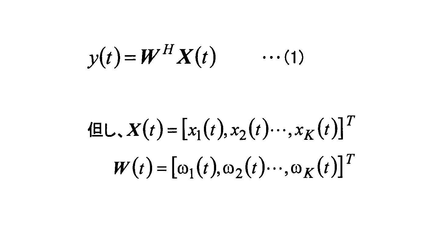
- the array-like data when sampling is performed at each location is X (t), the weight is W (t), the sampling period is T, and the array output y (t) is expressed by the following equation (1):
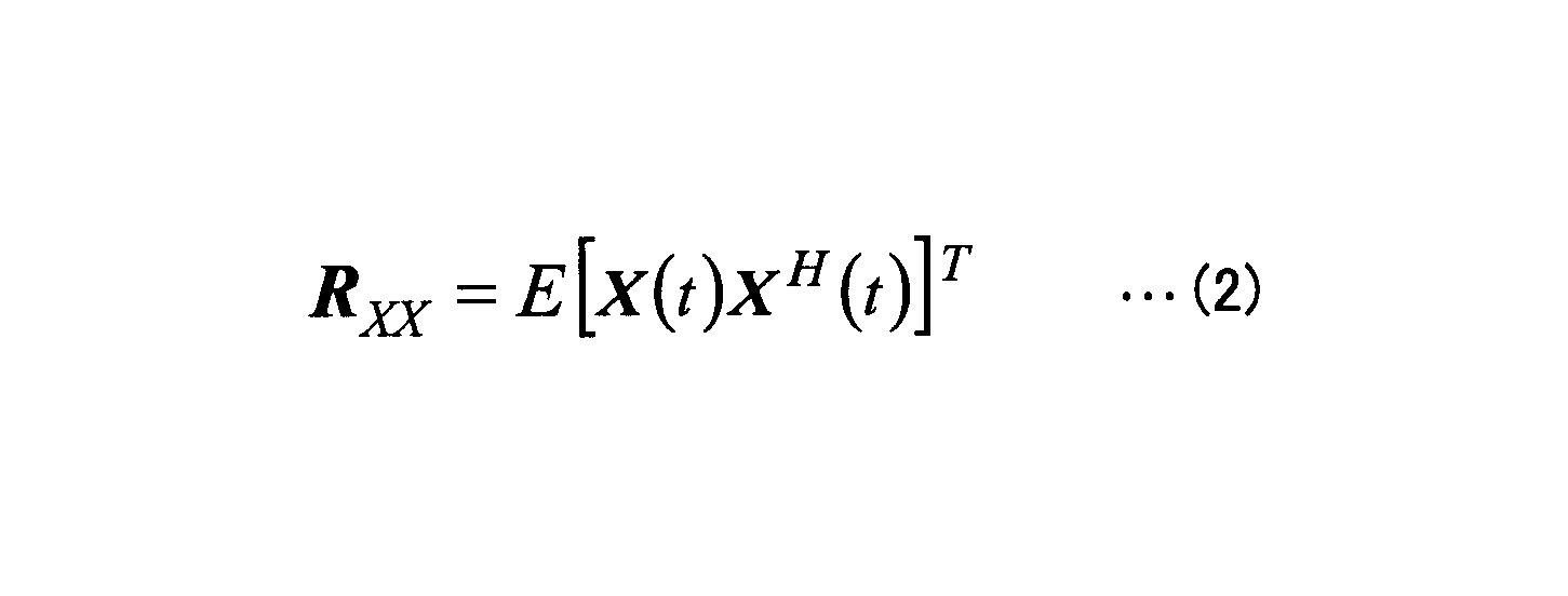
- the autocorrelation matrix Rxx is expressed by the following equation (2)
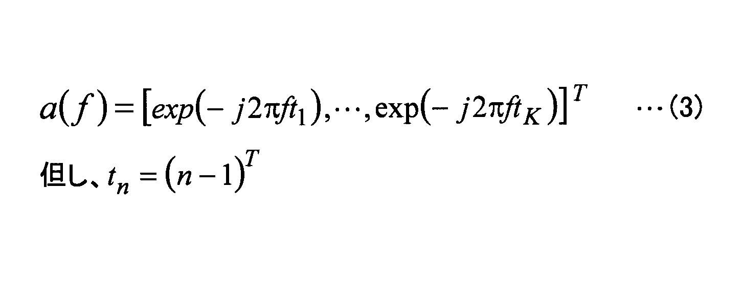
- the mode vector a (f) is expressed by the following equation (3)
- the frequency spectrum data is expressed by the following equation (4).
- the amount of calculation for obtaining frequency spectrum data from N-point sampling data is O (N 3 ).
- control circuit 16 When the control circuit 16 obtains the frequency spectrum data by the high resolution processing as described above, the control circuit 16 next executes a search for changing the frequency with respect to the frequency spectrum data, and the signal spectrum has a peak in the frequency spectrum data.
- the peak frequency is detected (step 160).
- the peak frequency of the frequency spectrum data obtained by this high resolution processing has a narrower frequency peak width and higher accuracy than that obtained by the FFT processing described above.
- the detection of the peak frequency in the above-described step 160 may be performed so long as the frequency at which the peak of the signal intensity is equal to or higher than the threshold value is extracted. The minimum signal strength is sufficient.
- a plurality of peak frequencies can be obtained.
- the same waveform that is line-symmetric with respect to the left and right around the half of the sampling frequency appears by the Nyquist theorem, so the peak frequency for one target is 1/2 of the sampling frequency. Appears in two places on the left and right of the center.
- the control circuit 16 detects the peak frequency of the frequency spectrum data by the high resolution processing as described above, the control circuit 16 estimates that the target exists at a distance from the own vehicle corresponding to the peak frequency, and detects the distance from the own vehicle to the target. To do. At this time, when there are a plurality of peak frequencies such that a plurality of targets exist, distance detection is performed for each target. And the control signal according to the detection distance is produced
- the signal processing for detecting the distance from the host vehicle to the target based on the reception result of the reflected wave of the transmission signal reflected by the target uses the FFT processing and the CAPON method.
- the high-resolution processing of the FDI method can be combined and performed in a hybrid manner.
- the beat signal sampling data (all data; for example, 1024 points) is subjected to FFT processing
- the entire frequency range of the frequency spectrum data obtained is searched to detect a relatively coarse peak frequency, and then Frequency spectrum data in the vicinity of the peak frequency (for example, 32 points or 16 points in total on the left and right centered at half the sampling frequency) is IFFT processed to return it to time axis data, and then the time axis data is processed with high resolution.
- the frequency spectrum data thus obtained is searched to detect a relatively precise peak frequency.
- the peak frequency of the frequency spectrum data obtained by the high resolution processing of the FDI method using the CAPON method is detected, compared to the configuration of detecting the peak frequency of the frequency spectrum data obtained only by the FFT processing.
- the peak frequency can be detected with high resolution, and the peak frequency detection accuracy can be increased. For this reason, according to the present embodiment, it is possible to detect the distance to the target with high resolution without increasing the bandwidth of the transmission signal.
- the peak frequency is detected not only by the high resolution processing of the FDI method using the CAPON method but by using both the high resolution processing and the FFT processing. Specifically, the entire frequency range of the frequency spectrum data by FFT processing is searched to detect the peak frequency, the frequency spectrum data in the vicinity of the peak frequency is returned to the time axis data, and the time axis data is converted to the frequency by high resolution processing. After conversion to spectrum data, the peak frequency is detected by searching the frequency spectrum data. For this reason, according to the present embodiment, the amount of calculation can be greatly reduced compared to a configuration in which the peak frequency is detected only by the high resolution processing of the FDI method using the CAPON method, and the distance to the target can be detected. This can be done with a relatively small amount of calculation.
- the amount of calculation O (N ⁇ log 10 N) for obtaining frequency spectrum data from 1024 points of sampling data by FFT processing is “3082”.
- the amount of calculation O (N 3 ) for obtaining the frequency spectrum data from the 1024-point sampling data by the FDI method using the CAPON method is “1.07 ⁇ 10 9 ”, which is the above-mentioned FFT processing. Compared to this, it becomes enormous and more than 340,000 times.
- the FFT processing of the sampling data of 1024 points is performed, and the IFFT processing and the high resolution processing of the total of 32 points of data centering on 1/2 of the sampling frequency.
- the frequency spectrum data is generated by performing the (FDI method using the CAPON method)
- the total calculation amount O ((1024 ⁇ log 10 1024) + (32 ⁇ log 10 32) + (32 3 ))
- Becomes “35893” which is suppressed to about 12 times that of the above-described FFT processing alone, and is significantly reduced as compared with the above-described high-resolution processing only.
- distance detection from the host vehicle to the target can be performed with a relatively small amount of calculation and high resolution without increasing the bandwidth of the transmission signal. For this reason, according to the radar apparatus 10 of the present embodiment, the distance from the host vehicle to the target can be detected with high accuracy by real-time processing, so that the control of the application apparatus using the target detection result is highly responsive. It can be accurate.
- the transmitting antenna 12a of the antenna 12 is the “transmitting means” described in the claims
- the receiving antenna 12b of the antenna 12 is the “receiving means” described in the claims.
- the control circuit 16 executes the process of step 110 in the routine shown in FIG. 2
- the “FFT conversion unit” described in the claims executes the process of step 120, thereby bringing the claims into the scope of the claims.
- the described “peak frequency detecting means” executes the process of step 130
- the “data extracting means” described in the claims executes the process of step 140.
- the “inverse FFT conversion means” executes the processing of steps 150 and 160, thereby realizing the “target detection means” recited in the claims.
- control circuit 16 executes the process of step 150, so that the “high resolution data converting means” described in the claims executes the process of step 160.
- the “high-resolution peak frequency detecting means” described in the claims detects the distance to the target based on the peak frequency obtained by the processing of step 160 above, thereby the “distance detection” described in the claims. Each means is realized.
- FIG. 6 shows a flowchart for explaining processing generally performed before and after the FFT processing.
- steps that execute the same processing as the steps shown in FIG. 2 are given the same reference numerals and description thereof is omitted.
- FIG. 7 shows a distance detection result by only the FFT process, a distance detection result by the process of the first embodiment, and a distance detection result by the process of the second embodiment when two targets are close to each other.
- the figure showing the simulation result of is shown.
- FIG. 7A shows a specific positional relationship between the radar apparatus and the two targets
- FIG. 7B shows a distance detection result only by FFT processing in the positional relationship shown in FIG. 7A.
- FIG. 7 (C) shows the distance detection result by the processing of the first embodiment in the positional relationship shown in FIG. 7 (A)
- FIG. 7 (D) shows the positional relationship shown in FIG. 7 (A).
- the distance detection results by the processing of the second embodiment are respectively shown.
- window function calculation is performed as preprocessing of FFT processing, and FFT processing is performed.
- post-processing blank subtraction processing and integration processing are performed.
- the window function is a weighting function for setting data outside a predetermined finite interval to zero, and is, for example, a Hanning window, a Hamming window, a Blackman window, or the like.
- the integration process is a process for improving the S / N ratio by integrating data sampled a plurality of times instantaneously on the frequency axis.
- the blank subtraction process is a process for suppressing noise inherent to the circuit such as coupling noise by subtracting data (blank data) sampled in advance in an environment without reflected waves from the received signal.
- the data is processed before and after the FFT processing. Therefore, when the processed data is converted into time-axis data by inverse Fourier transform (IFFT) processing, There is a high possibility that the time axis data does not return to the desired waveform. In such a situation, even if converted to frequency spectrum data by high resolution processing after the IFFT processing, the peak frequency of the frequency spectrum data by the high resolution processing cannot be accurately detected, and as a result, the distance to the target May not be detected accurately.
- IFFT inverse Fourier transform
- the two targets T1 and T2 are located 30 cm away from each other at a position about 2 meters from the antenna 12 of the radar apparatus, the two targets T1 are obtained only by FFT processing. , T2 cannot be detected separately (see FIG. 7B).
- the level difference between the peaks representing the two targets T1 and T2 is relatively small (about 1 db), It is difficult to separate the peaks, and the frequency interval (distance interval) between the peaks does not coincide with the actual interval (30 cm) (about 50 cm; see FIG. 7C).
- the above problem is solved by signal processing in the control circuit 16 to further improve the accuracy of target detection.
- signal processing in the control circuit 16 to further improve the accuracy of target detection.
- FIG. 8 shows a flowchart of an example of a control routine executed by the control circuit 16 in the radar apparatus 10 of the present embodiment.
- steps that execute the same processing as the steps shown in FIG. 2 are given the same reference numerals and description thereof is omitted.
- control circuit 16 when the control circuit 16 takes in the beat signal of the transmission signal and the reception signal from the high frequency circuit 14 into the A / D converter and samples the data at a predetermined sampling period (step 100), first, Then, pre-processing is performed on the sampling data (step 200). This preprocessing is a window function calculation. Then, the time axis data is converted into frequency spectrum data by performing Fourier transform (FFT) processing on the digital data after the window function calculation (step 210).
- FFT Fourier transform
- control circuit 16 performs post-processing on the frequency spectrum data obtained by the FFT processing in Step 210 (Step 220 and Step 230).
- This post-processing is a processing process performed to sharpen the peak with respect to the frequency spectrum data obtained by the FFT process, and specifically, the integration process and the blank subtraction process.
- the control circuit 16 executes a search for changing the frequency with respect to the post-processed frequency spectrum data, and the peak frequency at which the signal intensity peaks in the frequency spectrum data. Is detected (step 240).
- the peak frequency of the frequency spectrum data after this post-processing has a wide frequency peak width and a low accuracy compared to that according to the FDI method using the CAPON method described later.
- control circuit 16 takes in the beat signal of the transmission signal and the reception signal from the high frequency circuit 14 into the A / D converter, samples the data at a predetermined sampling period (step 100), and further In addition to the processing in steps 200 to 240, the digital data after sampling is subjected to Fourier transform (FFT) processing without performing the above pre-processing and post-processing. Thus, the time axis data is converted into frequency spectrum data (step 260).
- FFT Fourier transform
- control circuit 16 When the control circuit 16 detects the peak frequency in the step 240 and obtains the frequency spectrum data by the FFT process in the step 260, the control circuit 16 then performs the step on the frequency spectrum data obtained by the FFT process in the step 260. Data in the vicinity of the peak frequency detected at 240 (both the two left and right peak frequencies centered on 1/2 of the sampling frequency) are cut out, and frequency spectrum data only in the vicinity of the peak frequency is created (step 270).
- the extraction of the vicinity of the peak frequency from the frequency spectrum data may be performed in a predetermined frequency range centering on the peak frequency.
- the partial frequency spectrum data after being cut out is a waveform that is line-symmetric with respect to the left and right about a half of the sampling frequency, like the original frequency spectrum data.
- quadrature detection is performed with a mixer, the peak frequency is only on one side, so in this case only one location is cut out.
- control circuit 16 performs inverse Fourier transform (IFFT) processing on the frequency spectrum data only in the vicinity of the peak frequency generated in step 270, and returns the frequency spectrum data to time axis data (step 280).
- IFFT inverse Fourier transform
- This time axis data becomes time sampling data in which the data amount is reduced with respect to the time axis data of the sampling data obtained by sampling in the initial sampling period.
- the control circuit 16 converts the time axis data into frequency spectrum data by performing high resolution processing on the time axis data obtained by IFFT processing as described above (step 290).
- a search for changing the frequency is executed, and a peak frequency at which the signal intensity reaches a peak is detected in the frequency spectrum data (step 300).
- the CAPON method which is one of the FDI methods, is used for the high resolution processing.
- the peak frequency of the frequency spectrum data obtained by the above high resolution processing has a narrower frequency peak width and high accuracy than that by the above FFT processing.
- the control circuit 16 detects the peak frequency of the frequency spectrum data by the high resolution processing as described above, the control circuit 16 estimates that the target exists at a distance from the own vehicle corresponding to the peak frequency, and detects the distance from the own vehicle to the target. To do. At this time, when there are a plurality of peak frequencies such that a plurality of targets exist, distance detection is performed for each target. And the control signal according to the detection distance is produced
- the signal processing for detecting the distance from the host vehicle to the target based on the reception result of the reflected wave of the transmission signal reflected by the target uses the FFT processing and the CAPON method.
- the high-resolution processing of the FDI method can be combined and performed in a hybrid manner.
- the frequency spectrum data obtained by the FFT processing including the pre-processing and post-processing for the sampling data (total data; for example, 1024 points) of the beat signal a relatively coarse peak frequency is obtained.
- the frequency spectrum data is obtained by the FFT processing without the pre-processing and post-processing for the sampling data (all data; for example, 1024 points) of the beat signal, and the obtained frequency Data near the detected peak frequency is extracted from the spectrum data (for example, 32 points or 16 points in total on the left and right with a half of the sampling frequency as the center), and the extracted data is subjected to IFFT processing to obtain time axis data.
- Time axis data after returning It searches the frequency spectrum data obtained by the high-resolution process to detect a relatively detailed peak frequency.
- the peak frequency of the frequency spectrum data obtained by the high resolution processing of the FDI method using the CAPON method is detected, compared to the configuration of detecting the peak frequency of the frequency spectrum data obtained only by the FFT processing.
- the peak frequency can be detected with high resolution, and the peak frequency detection accuracy can be increased. Further, the detection of the peak frequency is not performed only by the high resolution processing of the FDI method using the CAPON method, but is performed using both the high resolution processing and the FFT processing.
- the distance detection from the own vehicle to the target can be performed with a relatively small calculation amount and high resolution without increasing the bandwidth of the transmission signal. For this reason, according to the radar apparatus 10 of the present embodiment, the distance from the host vehicle to the target can be detected with high accuracy by real-time processing, so that the control of the application apparatus using the target detection result is highly responsive. It can be accurate.
- the frequency spectrum data that is the target for detecting the peak frequency involves pre-processing and post-processing before and after the FFT processing. For this reason, the sensitivity fall of the peak frequency which has a big influence on target detection is suppressed.
- frequency spectrum data in which data in the vicinity of the peak frequency is cut out and then converted into time-axis data by IFFT processing is not accompanied by pre-processing and post-processing before and after the FFT processing. For this reason, data processed by pre-processing and post-processing before and after FFT processing is not cut out as frequency spectrum data converted to time-axis data by IFFT processing, and converted to time-axis data by IFFT processing. Therefore, the time axis data after IFFT processing can be returned to a desired waveform.
- the radar apparatus 10 of this embodiment has two The level difference between the peaks representing the targets T1 and T2 is relatively large, the peaks can be easily separated, and the frequency interval (distance interval) between these peaks is substantially the same as the actual interval (30 cm) (FIG. 7). (See (D)).
- the radar apparatus 10 of this embodiment the peak frequency of the frequency spectrum data by the high resolution processing after the IFFT processing is accurately detected while detecting the peak frequency of the frequency spectrum data by the FFT processing with high sensitivity (coarse peak detection). It can be detected well (fine peak detection). For this reason, according to the present Example, the further precision improvement of the distance detection from the own vehicle to a target can be aimed at.
- the control circuit 16 executes the process of step 200 in the routine shown in FIG. 8 so that the “preprocessing means” described in the claims performs the process of step 210.
- the “post-processing means” described in the claims by executing the processing in steps 220 and 230 causes the processing in step 240 to be performed.
- the “peak frequency detection means” described in the claims by executing the process of step 260 causes the “second FFT conversion means” described in the claims to execute the process of step 270.
- the “data extracting means” described in the claims by executing the process described in the claims executes the processing of step 280.
- “Inverse FFT transformation means”, described in the claims by performing the processing of steps 290, 300 "Target detection means" are realized respectively.
- control circuit 16 executes the process of step 290, so that the “high resolution data converting means” described in the claims executes the process of step 300.
- the “high-resolution peak frequency detection means” described in the claims detects the distance to the target based on the peak frequency obtained by the processing in step 300 above, thereby the “distance detection” described in the claims. Each means is realized.
- the FFT processing is performed after the sampling data is pre-processed by the window function calculation, and the post-processing is performed on the frequency spectrum data obtained by the FFT processing.
- the post-processing described above may be performed when the S / N ratio is relatively low, and may not be performed when the S / N ratio is relatively high.
- the FDI method using the CAPON method is used as the high resolution processing.
- the present invention is not limited to this, and other than the CAPON method, The FDI method using the MUSIC method or the ESPRIT method may be used.
- the time axis data is converted into frequency spectrum data by high resolution processing, and the distance to the target is detected based on the peak frequency of the frequency spectrum data.
- the present invention is not limited to this, and depending on the high resolution processing, the time axis data may not be converted into frequency spectrum data, and the distance to the target may be detected directly.
- This high resolution processing is, for example, the ESPRIT method.
Abstract
ターゲット検出を送信信号の帯域幅を広げることなく比較的少ない計算量で高分解能に行うことが可能なレーダ装置を提供する。受信手段に受信された受信信号を周波数スペクトラムデータにフーリエ変換するFFT変換手段と、そのフーリエ変換により得られた周波数スペクトラムデータのピーク周波数を検出するピーク周波数検出手段と、上記のフーリエ変換により得られた周波数スペクトラムデータから上記のピーク周波数近傍のデータを抽出するデータ抽出手段と、その抽出されたピーク周波数近傍のデータを時間軸データに逆フーリエ変換する逆FFT変換手段と、その逆フーリエ変換により得られた時間軸データに対して高分解能処理を行うことでターゲットを検出するターゲット検出手段と、を備える。
Description
本発明は、レーダ装置に係り、特に、送信信号を送信する送信手段と、送信信号の反射波を受信信号として受信する受信手段と、を備え、受信手段に受信された受信信号を処理してターゲットを検出するうえで好適なレーダ装置に関する。
従来、ターゲットからの反射波を受信して得た受信信号を処理してターゲットを検出するレーダ装置が知られている(例えば、特許文献1参照)。このレーダ装置は、送信信号の周波数を増加させる区間と減少させる区間とを繰り返すことで連続的に変化させつつ、ターゲットで反射した反射波を受信信号として受信し、その受信信号を処理してターゲットまでの距離を検出する。
FM-CWレーダ装置においてターゲット検出を行ううえで一般的なフーリエ変換を用いて周波数分析を行った場合は、分解能が低いので、互いに近接したターゲットを区別して検出することができないおそれがある。レーダ装置の距離分解能は、一般的に、送信信号の帯域幅に依存するので、ターゲットまでの距離を高分解能に検出するためには、レーダ装置の送信信号の帯域幅を広げることが有効である。しかし、レーダ装置の広帯域化では、高価な素子や回路,アンテナが必要となるので、製造コストが増大すると共に、特に帯域幅が500MHz以上である超広帯域(UWB)レーダでは、送信電力が電波法により大幅に制限されるので、ターゲットを探知できる距離が短くなってしまう。
そこで、レーダ装置の帯域幅を広げることなく距離分解能を高める手法として、周波数が僅かに異なる複数の送信信号を送信し、複数の受信信号間の位相差に基づいてターゲットを検出することで、レーダ装置の帯域幅に基づくものに比べて高い分解能を得るFDI(Frequency Domain Interferometry;周波数干渉計)法がある。
ところで、上記の如く複数の受信信号間の位相差を合成する手法としては、方位の高分解能処理として代表的なCAPON法やMUSIC法,ESPRIT法などが知られている。しかし、かかるCAPON法などの演算手法を用いたFDI法をFM-CWレーダに適用して分解能を向上させる技術が特許文献1等で知られているが、この方法では、その計算量がフーリエ変換での計算量に比べて膨大になるので、リアルタイム処理が困難となり、その結果として、その演算手法を、処理時間や演算速度が限られた例えば車載レーダ装置などに適用することはできない。
本発明は、上述の点に鑑みてなされたものであり、ターゲット検出を送信信号の帯域幅を広げることなく比較的少ない計算量で高分解能に行うことが可能なレーダ装置を提供することを目的とする。
上記の目的は、送信信号を送信する送信手段と、前記送信信号の反射波を受信信号として受信する受信手段と、を備え、前記受信手段に受信された前記受信信号を処理してターゲットを検出するレーダ装置であって、前記受信手段に受信された前記受信信号を周波数スペクトラムデータにフーリエ変換するFFT変換手段と、前記FFT変換手段による演算結果として得られた周波数スペクトラムデータのピーク周波数を検出するピーク周波数検出手段と、前記FFT変換手段による演算結果として得られた周波数スペクトラムデータから、前記ピーク周波数検出手段により検出された前記ピーク周波数近傍のデータを抽出するデータ抽出手段と、前記データ抽出手段により抽出された前記ピーク周波数近傍のデータを時間軸データに逆フーリエ変換する逆FFT変換手段と、前記逆FFT変換手段による演算結果として得られた前記時間軸データに対して高分解能処理を行うことでターゲットを検出するターゲット検出手段と、を備えるレーダ装置により達成される。
また、上記の目的は、送信信号を送信する送信手段と、前記送信信号の反射波を受信信号として受信する受信手段と、を備え、前記受信手段に受信された前記受信信号を処理してターゲットを検出するレーダ装置であって、前記受信手段に受信された前記受信信号に対して窓関数演算を行う前処理手段と、前記前処理手段による演算結果として得られたデータを周波数スペクトラムデータにフーリエ変換する第1のFFT変換手段と、前記第1のFFT変換手段による演算結果として得られた周波数スペクトラムデータに対して後処理を行う後処理手段と、前記後処理手段による演算結果として得られた周波数スペクトラムデータのピーク周波数を検出するピーク周波数検出手段と、前記受信手段に受信された前記受信信号を周波数スペクトラムデータにフーリエ変換する第2のFFT変換手段と、前記第2のFFT変換手段による演算結果として得られた周波数スペクトラムデータから、前記ピーク周波数検出手段により検出された前記ピーク周波数近傍のデータを抽出するデータ抽出手段と、前記データ抽出手段により抽出された前記ピーク周波数近傍のデータを時間軸データに逆フーリエ変換する逆FFT変換手段と、前記逆FFT変換手段による演算結果として得られた前記時間軸データに対して高分解能処理を行うことでターゲットを検出するターゲット検出手段と、を備えるレーダ装置により達成される。
本発明によれば、ターゲット検出を送信信号の帯域幅を広げることなく比較的少ない計算量で高分解能に行うことができる。
以下、図面を用いて、本発明に係るレーダ装置の具体的な実施の形態について説明する。
図1は、本発明の第1実施例であるレーダ装置10の構成図を示す。レーダ装置10は、例えば車両や飛行体などの移動体に搭載されており、自移動体の周囲に存在するターゲット(物標)を検出する周辺監視装置である。レーダ装置10は、例えば、周波数変調した送信波を送信し、ターゲットにより反射される反射波を受信することにより、所定範囲内のターゲットを検出するFM-CW方式のレーダ装置に適用されるものとすればよい。
図1に示す如く、レーダ装置10は、アンテナ12と、高周波回路14と、制御回路16と、を備えている。尚、本実施例のレーダ装置10は、車両に搭載されるものとし、FM-CW方式で自車両周囲のターゲットを検出し、レーダ装置10において検出されたターゲットのデータは、例えば車両に搭載される車間制御装置や速度制御装置,制動装置などのアプリケーション装置に提供・出力されて使用される。
アンテナ12は、車体前部や車体後部のバンパーなどに配設されている。アンテナ12は、送信すべき送信信号を外部空間へ照射する送信アンテナ12aと、送信アンテナ12aから送信された送信信号がターゲットに反射して生成される反射波を受信する受信アンテナ12bと、からなる。送信アンテナ12aは、車両周囲(例えば、車両進行方向)の所定範囲内に送信信号を送信する。また、受信アンテナ12bは、所定範囲内から反射される反射波を受信信号として受信することができる。
高周波回路14は、発振器及び混合器を有している。この発振器は、周波数が経時的に変化する発振信号を出力する。上記したアンテナ12の送信アンテナ12aは、高周波回路14の発振器に接続されている。送信アンテナ12aは、発振器から供給された発振信号に応答して、周波数が経時的に変化する電磁波である送信信号(例えばミリ波)を送信する。
高周波回路14において、上記の混合器には、上記の発振器及び受信アンテナ12bが接続されている。受信アンテナ12bに受信された反射波は、受信信号として混合器に供給される。混合器は、発振器から出力される発振信号と受信アンテナ12bから供給される受信信号とを混合し、両信号の周波数差であるビート周波数を有するビート信号を生成する。
制御回路16は、高周波回路14の混合器に接続するA/D変換器を有している。混合器で生成されたビート信号は、制御回路16のA/D変換器に入力される。このA/D変換器は、高周波回路14の混合器から供給されたアナログ信号であるビート信号をデジタル信号に変換する。このA/D変換器によるA/D変換は、予め定められた所定のサンプリング周期で行われる。
制御回路16は、後述の如く信号処理を行って自車両から所定範囲内に存在するターゲットを検出する。具体的には、A/D変換により得たデジタル信号についてフーリエ変換(FFT)処理などを行うことで周波数スペクトラムデータを生成し、その周波数スペクトラムデータからターゲットの位置に応じた周波数成分(振幅及び位相)を抽出し、その抽出した周波数成分に基づいて、自車両からターゲットまでの距離、自車両とターゲットとの相対速度、及び自車両に対するターゲットの方位(角度)を検出する。そして、その検出したターゲットを制御対象として認識して、その認識結果に応じた制御信号をアプリケーション装置へ向けて出力する。
次に、図2~図5を参照して、本実施例のレーダ装置10におけるターゲットを検出する手法について説明する。
図2は、本実施例のレーダ装置10において制御回路16が実行する制御ルーチンの一例のフローチャートを示す。図3は、本実施例のレーダ装置10において制御回路16がターゲットを検出する過程で生成される波形の一例を表した図を示す。図4は、本実施例のレーダ装置10において制御回路16がターゲットを検出する手法を模式的に表した図を示す。また、図5は、本実施例のレーダ装置10において制御回路16が受信信号に対して行うサンプリングとアレー出力との関係を表した図を示す。
本実施例において、アプリケーション装置などが起動されることでレーダ装置10が起動されると、その起動中、高周波回路14の発振器から発振信号が出力されることで、車両のアンテナ12の送信アンテナ12aから送信信号が外部空間へ照射されると共に、受信アンテナ12bでの受信処理が行われる。送信アンテナ12aから送信される送信信号は、送信周波数が経時的に変化する信号である。
送信信号の照射範囲内にターゲットが存在しないときは、送信アンテナ12aから送信された送信信号がターゲットに反射しないので、ターゲットに反射される送信信号の反射波自体が存在せず、この場合は、受信アンテナ12bに受信される受信波の強度は比較的小さい。一方、送信信号の照射範囲内にターゲットが存在するときは、送信アンテナ12aから送信された送信信号がそのターゲットで反射して、そのターゲットに反射された送信信号の反射波が受信アンテナ12bに受信される。この場合は、受信アンテナ12bに受信される受信波の強度は比較的大きい。
受信アンテナ12bに送信信号の反射波が受信されると、その受信信号は、高周波回路14の混合器に供給されることで、発振器からの周波数が経時的に変化する発振信号と混合される。混合器は、受信アンテナ12bからの受信信号と発振器からの発振信号とを混合してビート信号を生成する。ビート信号の周波数は自車両から対象物までの距離を表し、また、ビート信号のレベルは受信反射波の強度を表す。混合器で生成されたビート信号は、制御回路16へ出力される。
制御回路16は、高周波回路14からのアナログ信号である上記のビート信号をA/D変換器に取り込み、所定のサンプリング周期でデータのサンプリングを行ってデジタル変換を行う(ステップ100)。制御回路16は、所定のサンプリング周期でサンプリングして得たデジタルデータに対してフーリエ変換(FFT)処理を施すことで、時間軸データを周波数スペクトラムデータに変換する(ステップ110)。FFT処理において、Nポイント(例えば、1024ポイント)のサンプリングデータから周波数スペクトラムデータを得るうえでの計算量は、O(N・log10N)である。
次に、制御回路16は、上記の如くFFT処理により求めた周波数スペクトラムデータに対して周波数を変化させる探索を実行し、その周波数スペクトラムデータの中で信号強度がピークとなる周波数(ピーク周波数)を検出する(ステップ120)。このFFT処理により求めた周波数スペクトラムデータのピーク周波数は、後述のCAPON法を用いたFDI法によるものに比べて周波数ピーク幅が広く精度の低いものとなる。
尚、上記ステップ120におけるピーク周波数の検出は、信号強度のピークが閾値以上となる周波数を抽出するものであればよく、この場合、閾値は、自車両において検出すべきターゲットを検出するのに必要な最小の信号強度であればよい。また、送信信号の照射範囲内にターゲットが複数存在する場合は、複数のピーク周波数が得られる。更に、FFT処理により得られる周波数スペクトラムデータでは、ナイキスト定理によりサンプリング周波数の1/2を中心にして左右で線対称の同じ波形が現れるため、一ターゲットに対するピーク周波数は、図3(A)に示す如く、サンプリング周波数の1/2を中心にして左右に2箇所現れる。
制御回路16は、上記の如くFFT処理による周波数スペクトラムデータのピーク周波数を検出すると、次に、その周波数スペクトラムデータ上でそのピーク周波数(サンプリング周波数の1/2を中心にした左右2箇所のピーク周波数とも)近傍のデータを切り出し、そのピーク周波数近傍のみの周波数スペクトラムデータを作成する(ステップ130)。
尚、この周波数スペクトラムデータからのピーク周波数近傍の切り出しは、ピーク周波数を中心にして予め定められた周波数範囲(図3(A)に破線で囲まれる領域)において行われるものとすればよい。また、この切り出された後の部分的な周波数スペクトラムデータは、図3(B)に示す如く、元の周波数スペクトラムデータ(図3(A)に示す)と同様に、サンプリング周波数の1/2を中心にして左右で線対称の波形である。ただし、混合器で直交検波を行った場合は、ピーク周波数は片側のみとなるので、この場合は一箇所のみ切り出す。
制御回路16は、上記の如くピーク周波数近傍のみの周波数スペクトラムデータについて逆フーリエ変換(IFFT)処理を施して、その周波数スペクトラムデータを時間軸データに戻す(ステップ140)。この時間軸データは、当初サンプリング周期でサンプリングして得たサンプリングデータの時間軸データに対してデータ量が削減された時間サンプリングデータとなる。尚、このIFFT処理において、周波数スペクトラムデータ上のNポイント(例えば、サンプリング周波数の1/2を中心にした左右トータルで32ポイントや16ポイント)のデータから時間軸データを得るうえでの計算量は、O(N・log10N)である。
次に、制御回路16は、上記の如くIFFT処理により求めた時間軸データに対して高分解能処理を施すことで、時間軸データを周波数スペクトラムデータに変換する(ステップ150)。この高分解能処理は、図4に示す如く、周波数が僅かに異なる複数の送信信号を送信アンテナ12aから送信し、周波数が僅かに異なる複数の反射波を受信アンテナ12bで受信し、それら複数の受信信号間の位相差に基づいてターゲットを検出するFDI(Frequency Domain Interferometry;周波数干渉計)法の一つであるCAPON法を用いる。
具体的には、制御回路16は、送信信号の帯域幅を広げることなく自車両からターゲットまでの距離を検出する際の距離分解能を高める高分解能処理として、図5に示す如く、時間が異なるK箇所でそれぞれサンプリングを行った際のアレー状のデータをX(t)としかつその重みをW(t)とし、サンプリング周期をTとし、アレー出力y(t)を次式(1)で表し、自己相関行列Rxxを次式(2)とし、モードベクトルa(f)を次式(3)とすると、周波数スペクトラムデータを次式(4)で表す。この高分解能処理(CAPON法を利用したFDI法)において、Nポイントのサンプリングデータから周波数スペクトラムデータを得るうえでの計算量は、O(N3)である。

尚、上記ステップ160におけるピーク周波数の検出は、信号強度のピークが閾値以上となる周波数を抽出するものであればよく、この場合、閾値は、自車両において検出すべきターゲットを検出するのに必要な最小の信号強度であればよい。また、送信信号の照射範囲内にターゲットが複数存在する場合は、複数のピーク周波数が得られる。更に、高分解能処理により得られる周波数スペクトラムデータでは、ナイキスト定理によりサンプリング周波数の1/2を中心にして左右で線対称の同じ波形が現れるため、一ターゲットに対するピーク周波数は、サンプリング周波数の1/2を中心にして左右に2箇所現れる。
制御回路16は、上記の如く高分解能処理による周波数スペクトラムデータのピーク周波数を検出すると、そのピーク周波数に相当する自車両からの距離にターゲットが存在すると推定し、自車両からターゲットまでの距離を検出する。尚、この際、ピーク周波数が、複数のターゲットが存在するように複数あるときは、ターゲットごとに距離検出を行う。そして、その検出距離に応じた制御信号を生成し、アプリケーション装置への制御出力を行う。
このように、本実施例のレーダ装置10においては、ターゲットで反射した送信信号の反射波の受信結果に基づいて自車両からターゲットまでの距離を検出する信号処理を、FFT処理とCAPON法を利用したFDI法の高分解能処理とを組み合わせてハイブリッドで行うことができる。
具体的には、一旦、ビート信号のサンプリングデータ(全データ;例えば1024ポイント)をFFT処理することにより求めた周波数スペクトラムデータの全周波数範囲を探索して比較的粗いピーク周波数を検出し、その後、そのピーク周波数近傍の周波数スペクトラムデータ(例えば、サンプリング周波数の1/2を中心にした左右トータルで32ポイントや16ポイント)をIFFT処理して時間軸データに戻した後にその時間軸データを高分解能処理することにより求めた周波数スペクトラムデータを探索して比較的精しいピーク周波数を検出する。
かかる構成によれば、CAPON法を利用したFDI法の高分解能処理により求めた周波数スペクトラムデータのピーク周波数を検出するので、FFT処理のみにより求めた周波数スペクトラムデータのピーク周波数を検出する構成に比べて、ピーク周波数を高い分解能で検出することができ、ピーク周波数の検出精度を高めることができる。このため、本実施例によれば、送信信号の帯域幅を広げることなくターゲットまでの距離検出を高分解能に行うことができる。
また、上記の構成によれば、ピーク周波数の検出を、CAPON法を利用したFDI法の高分解能処理のみにより行うものではなく、その高分解処理とFFT処理との双方を用いて行う。具体的には、FFT処理による周波数スペクトラムデータの全周波数範囲を探索してピーク周波数を検出し、そのピーク周波数近傍の周波数スペクトラムデータを時間軸データに戻し、その時間軸データを高分解能処理により周波数スペクトラムデータに変換した後に、その周波数スペクトラムデータを探索してピーク周波数を検出する。このため、本実施例によれば、CAPON法を利用したFDI法の高分解能処理のみによりピーク周波数を検出する構成に比べて、計算量を大幅に削減することができ、ターゲットまでの距離検出を比較的少ない計算量で行うことができる。
例えばFM-CW方式のレーダ装置において、1024ポイントのサンプリングデータからFFT処理により周波数スペクトラムデータを得るうえでの計算量O(N・log10N)は、“3082”となる。一方、1024ポイントのサンプリングデータからCAPON法を利用したFDI法により周波数スペクトラムデータを得るうえでの計算量O(N3)は、“1.07×10⁹”となり、上記のFFT処理のものに比べて膨大になり、34万倍以上となる。
これに対して、本実施例のレーダ装置10の如く、1024ポイントのサンプリングデータのFFT処理を経て、サンプリング周波数の1/2を中心にした左右トータルで32ポイントのデータのIFFT処理及び高分解能処理(CAPON法を利用したFDI法)を行うことで周波数スペクトラムデータを生成する場合は、そのトータルの計算量O((1024・log101024)+(32・log1032)+(323))は、“35893”となり、上記のFFT処理のみのものの12倍程度に抑えられると共に、上記の高分解能処理のみのものに比べて大幅に削減される。
従って、本実施例のレーダ装置10によれば、自車両からターゲットまでの距離検出を送信信号の帯域幅を広げることなく比較的少ない計算量で高分解能に行うことができる。このため、本実施例のレーダ装置10によれば、自車両からターゲットまでの距離検出をリアルタイム処理で高精度に行うことができるので、ターゲット検出結果を用いたアプリケーション装置の制御を応答性よく高精度なものとすることができる。
尚、上記の第1実施例においては、アンテナ12の送信アンテナ12aが特許請求の範囲に記載した「送信手段」に、アンテナ12の受信アンテナ12bが特許請求の範囲に記載した「受信手段」に、それぞれ相当している。また、制御回路16が、図2に示すルーチン中ステップ110の処理を実行することにより特許請求の範囲に記載した「FFT変換手段」が、ステップ120の処理を実行することにより特許請求の範囲に記載した「ピーク周波数検出手段」が、ステップ130の処理を実行することにより特許請求の範囲に記載した「データ抽出手段」が、ステップ140の処理を実行することにより特許請求の範囲に記載した「逆FFT変換手段」が、ステップ150,160の処理を実行することにより特許請求の範囲に記載した「ターゲット検出手段」が、それぞれ実現されている。
また、上記の第1実施例においては、制御回路16が、ステップ150の処理を実行することにより特許請求の範囲に記載した「高分解能データ変換手段」が、ステップ160の処理を実行することにより特許請求の範囲に記載した「高分解能ピーク周波数検出手段」が、上記ステップ160の処理により得られたピーク周波数に基づいてターゲットまでの距離を検出することにより特許請求の範囲に記載した「距離検出手段」が、それぞれ実現されている。
図6は、一般的にFFT処理の前後で行われる処理を説明するためのフローチャートを示す。尚、図6において、上記図2に示すステップと同一の処理を実行するステップについては、同一の符号を付してその説明を省略する。また、図7は、2つのターゲットが互いに近接して存在する場合の、FFT処理のみによる距離検出結果と、第1実施例の処理による距離検出結果と、第2実施例の処理による距離検出結果と、のシミュレーション結果を表した図を示す。尚、図7(A)にはレーダ装置と2つのターゲットとの具体的な位置関係を、図7(B)には図7(A)に示す位置関係でのFFT処理のみによる距離検出結果を、図7(C)には図7(A)に示す位置関係での第1実施例の処理による距離検出結果を、また、図7(D)には図7(A)に示す位置関係での第2実施例の処理による距離検出結果を、それぞれ示す。
ところで、FFT処理による周波数スペクトラムデータのピーク周波数を感度良く検出するためには、一般的に、図6に示す如く、データサンプリング後、FFT処理の前処理として窓関数演算が行われると共に、FFT処理の後処理としてブランク減算処理及び積分処理が行われる。尚、窓関数は、所定有限区間外のデータをゼロとする重み付け関数であって、例えば、ハニング窓やハミング窓,ブラックマン窓などである。また、積分処理は、瞬間的に複数回連続してサンプリングしたデータを周波数軸上で積分することで、S/N比の向上を図る処理である。更に、ブランク減算処理は、反射波の無い環境で予めサンプリングしておいたデータ(ブランクデータ)を受信信号から減算することで、カップリングノイズ等の回路固有のノイズを抑制する処理である。
一方、上記の前処理及び後処理が行われると、FFT処理の前後でデータが加工されるので、その加工されたデータが逆フーリエ変換(IFFT)処理で時間軸データに変換されると、その時間軸データが所望の波形に戻らない可能性が高い。かかる状況では、そのIFFT処理後に高分解能処理で周波数スペクトラムデータに変換されても、その高分解能処理による周波数スペクトラムデータのピーク周波数を精度よく検出することができず、その結果として、ターゲットまでの距離を精度よく検出することができないおそれがある。
例えば図7(A)に示す如く、レーダ装置のアンテナ12から2メートル程度の位置に2つのターゲット(円柱状)T1,T2が前後30cm離れて位置する場合、FFT処理のみでは、2つのターゲットT1,T2を区別して検出することができない(図7(B)参照)。また、上記した第1実施例においてFFT処理の前後に上記の前処理及び後処理が追加されたものでは、2つのターゲットT1,T2を表すピーク同士のレベル差が比較的小さく(1db程度)、ピークの分離が困難であると共に、それらピーク同士の周波数間隔(距離間隔)が実際の間隔(30cm)と一致していない(50cm程度;図7(C)参照)。
そこで、本発明の第2実施例は、制御回路16での信号処理により上記の不都合を解決してターゲット検出の更なる精度向上を図ることとしている。以下、図8を参照して、本実施例のレーダ装置10におけるターゲットを検出する手法について説明する。
すなわち、本実施例のレーダ装置10は、制御回路16に図2に代えて図8に示す制御ルーチンを実行させることにより実現される。図8は、本実施例のレーダ装置10において制御回路16が実行する制御ルーチンの一例のフローチャートを示す。尚、図8において、上記図2に示すステップと同一の処理を実行するステップについては、同一の符号を付してその説明を省略する。
本実施例において、制御回路16は、高周波回路14からの送信信号と受信信号とのビート信号をA/D変換器に取り込み、所定のサンプリング周期でデータのサンプリングを行うと(ステップ100)、まず、そのサンプリングデータに対して前処理を行う(ステップ200)。この前処理は、窓関数演算である。そして、その後、その窓関数演算後のデジタルデータに対してフーリエ変換(FFT)処理を施すことで、時間軸データを周波数スペクトラムデータに変換する(ステップ210)。
次に、制御回路16は、上記ステップ210におけるFFT処理により求めた周波数スペクトルデータに対して後処理を行う(ステップ220及びステップ230)。この後処理は、FFT処理により求めた周波数スペクトルデータに対してピークを先鋭にするために行う加工処理であって、具体的には、上記の積分処理及び上記のブランク減算処理である。
そして、制御回路16は、上記ステップ120と同様に、上記した後処理後の周波数スペクトラムデータに対して周波数を変化させる探索を実行し、その周波数スペクトラムデータの中で信号強度がピークとなるピーク周波数を検出する(ステップ240)。この後処理後の周波数スペクトラムデータのピーク周波数は、後述のCAPON法を用いたFDI法によるものに比べて周波数ピーク幅が広く精度の低いものとなる。
制御回路16は、上記の如く、高周波回路14からの送信信号と受信信号とのビート信号をA/D変換器に取り込み、所定のサンプリング周期でデータのサンプリングを行った後(ステップ100)、更に、上記ステップ200~240の処理とは別に、サンプリング後のデジタルデータに対して上記の前処理及び後処理を行うことなく、そのサンプリング後のデジタルデータに対してフーリエ変換(FFT)処理を施すことで、時間軸データを周波数スペクトラムデータに変換する(ステップ260)。
制御回路16は、上記ステップ240においてピーク周波数を検出し、かつ、上記ステップ260においてFFT処理により周波数スペクトルデータを求めると、次に、そのステップ260におけるFFT処理により求めた周波数スペクトルデータ上でそのステップ240で検出したピーク周波数(サンプリング周波数の1/2を中心にした左右2箇所のピーク周波数とも)近傍のデータを切り出し、そのピーク周波数近傍のみの周波数スペクトラムデータを作成する(ステップ270)。
尚、この周波数スペクトラムデータからのピーク周波数近傍の切り出しは、ピーク周波数を中心にして予め定められた周波数範囲において行われるものとすればよい。また、この切り出された後の部分的な周波数スペクトラムデータは、元の周波数スペクトラムデータと同様に、サンプリング周波数の1/2を中心にして左右で線対称の波形である。ただし、混合器で直交検波を行った場合は、ピーク周波数は片側のみとなるので、この場合は一箇所のみ切り出す。
次に、制御回路16は、上記ステップ270で生成したピーク周波数近傍のみの周波数スペクトラムデータについて逆フーリエ変換(IFFT)処理を施して、その周波数スペクトラムデータを時間軸データに戻す(ステップ280)。この時間軸データは、当初サンプリング周期でサンプリングして得たサンプリングデータの時間軸データに対してデータ量が削減された時間サンプリングデータとなる。
そして、制御回路16は、上記の如くIFFT処理により求めた時間軸データに対して高分解能処理を施すことで、時間軸データを周波数スペクトラムデータに変換し(ステップ290)、その周波数スペクトラムデータに対して周波数を変化させる探索を実行し、その周波数スペクトラムデータの中で信号強度がピークとなるピーク周波数を検出する(ステップ300)。尚、上記の高分解能処理は、上記のFDI法の一つであるCAPON法を用いる。また、上記の高分解能処理により求めた周波数スペクトラムデータのピーク周波数は、上述のFFT処理によるものに比べて周波数ピーク幅が狭く精度の高いものとなる。
制御回路16は、上記の如く高分解能処理による周波数スペクトラムデータのピーク周波数を検出すると、そのピーク周波数に相当する自車両からの距離にターゲットが存在すると推定し、自車両からターゲットまでの距離を検出する。尚、この際、ピーク周波数が、複数のターゲットが存在するように複数あるときは、ターゲットごとに距離検出を行う。そして、その検出距離に応じた制御信号を生成し、アプリケーション装置への制御出力を行う。
このように、本実施例のレーダ装置10においても、ターゲットで反射した送信信号の反射波の受信結果に基づいて自車両からターゲットまでの距離を検出する信号処理を、FFT処理とCAPON法を利用したFDI法の高分解能処理とを組み合わせてハイブリッドで行うことができる。
具体的には、ビート信号のサンプリングデータ(全データ;例えば1024ポイント)に対する上記の前処理及び後処理を伴うFFT処理により求めた周波数スペクトラムデータの全周波数範囲を探索して比較的粗いピーク周波数を検出すると共に、そのピーク周波数検出と並行して、ビート信号のサンプリングデータ(全データ;例えば1024ポイント)に対する上記の前処理及び後処理を伴わないFFT処理により周波数スペクトラムデータを求め、その求めた周波数スペクトルデータから上記の検出したピーク周波数近傍のデータ(例えば、サンプリング周波数の1/2を中心にした左右トータルで32ポイントや16ポイント)を切り出し、その切り出したデータをIFFT処理して時間軸データに戻した後にその時間軸データを高分解能処理することにより求めた周波数スペクトラムデータを探索して比較的精しいピーク周波数を検出する。
かかる構成によれば、CAPON法を利用したFDI法の高分解能処理により求めた周波数スペクトラムデータのピーク周波数を検出するので、FFT処理のみにより求めた周波数スペクトラムデータのピーク周波数を検出する構成に比べて、ピーク周波数を高い分解能で検出することができ、ピーク周波数の検出精度を高めることができる。また、ピーク周波数の検出を、CAPON法を利用したFDI法の高分解能処理のみにより行うものではなく、その高分解処理とFFT処理との双方を用いて行う。
従って、本実施例のレーダ装置10においても、自車両からターゲットまでの距離検出を送信信号の帯域幅を広げることなく比較的少ない計算量で高分解能に行うことができる。このため、本実施例のレーダ装置10によれば、自車両からターゲットまでの距離検出をリアルタイム処理で高精度に行うことができるので、ターゲット検出結果を用いたアプリケーション装置の制御を応答性よく高精度なものとすることができる。
また、本実施例の構成においては、ピーク周波数を検出する対象となる周波数スペクトラムデータは、FFT処理の前後で前処理及び後処理を伴うものである。このため、ターゲット検出に大きな影響を与えるピーク周波数の感度低下は抑えられる。一方、ピーク周波数近傍のデータが切り出されかつその後にIFFT処理で時間軸データに変換される周波数スペクトラムデータは、FFT処理の前後で前処理及び後処理を伴わないものである。このため、FFT処理の前後で前処理及び後処理により加工されたデータが、IFFT処理で時間軸データに変換される周波数スペクトラムデータとして切り出されることは無く、また、IFFT処理で時間軸データに変換されることは無いので、IFFT処理後の時間軸データを所望の波形に戻すことが可能である。
例えば図7(A)に示す如く、アンテナ12から2メートル程度の位置に2つのターゲット(円柱状)T1,T2が前後30cm離れて位置する場合、本実施例のレーダ装置10においては、2つのターゲットT1,T2を表すピーク同士のレベル差が比較的大きく、ピークの分離が容易であると共に、それらピーク同士の周波数間隔(距離間隔)が実際の間隔(30cm)と略同じである(図7(D)参照)。
従って、本実施例のレーダ装置10によれば、FFT処理による周波数スペクトラムデータのピーク周波数を感度良く検出(粗ピーク検出)しつつ、IFFT処理後の高分解能処理による周波数スペクトラムデータのピーク周波数を精度よく検出(精ピーク検出)することができる。このため、本実施例によれば、自車両からターゲットまでの距離検出の更なる精度向上を図ることができる。
尚、上記の第2実施例においては、制御回路16が、図8に示すルーチン中ステップ200の処理を実行することにより特許請求の範囲に記載した「前処理手段」が、ステップ210の処理を実行することにより特許請求の範囲に記載した「第1のFFT変換手段」が、ステップ220,230の処理を実行することにより特許請求の範囲に記載した「後処理手段」が、ステップ240の処理を実行することにより特許請求の範囲に記載した「ピーク周波数検出手段」が、ステップ260の処理を実行することにより特許請求の範囲に記載した「第2のFFT変換手段」が、ステップ270の処理を実行することにより特許請求の範囲に記載した「データ抽出手段」が、ステップ280の処理を実行することにより特許請求の範囲に記載した「逆FFT変換手段」が、ステップ290,300の処理を実行することにより特許請求の範囲に記載した「ターゲット検出手段」が、それぞれ実現されている。
また、上記の第2実施例においては、制御回路16が、ステップ290の処理を実行することにより特許請求の範囲に記載した「高分解能データ変換手段」が、ステップ300の処理を実行することにより特許請求の範囲に記載した「高分解能ピーク周波数検出手段」が、上記ステップ300の処理により得られたピーク周波数に基づいてターゲットまでの距離を検出することにより特許請求の範囲に記載した「距離検出手段」が、それぞれ実現されている。
更に、上記の第2実施例においては、サンプリングデータに対して窓関数演算による前処理を実施した後にFFT処理を施し、そのFFT処理により求めた周波数スペクトラムデータに対して後処理を実施することとしているが、S/N比が比較的高い場合には、かかる後処理を実施しなくてもよい。すなわち、上記の後処理は、S/N比が比較的低い場合に実施されるものとすればよく、S/N比が比較的高い場合には実施されなくてもよい。
ところで、上記の第1及び第2実施例においては、高分解能処理として、CAPON法を利用したFDI法を用いることとしているが、本発明はこれに限定されるものではなく、CAPON法以外に、MUSIC法やESPRIT法などを利用したFDI法を用いることとしてもよい。
また、上記の第1及び第2実施例においては、高分解能処理により時間軸データを周波数スペクトラムデータに変換し、その周波数スペクトラムデータのピーク周波数に基づいてターゲットまでの距離を検出するが、本発明はこれに限定されるものではなく、高分解能処理によっては、時間軸データを周波数スペクトラムデータに変換せず、直接にターゲットまでの距離を検出するものであってもよい。この高分解処理は、例えば、ESPRIT法などである。
尚、本国際出願は、2013年(平成25年)1月7日に出願した日本国特許出願2013-000694号に基づく優先権を主張するものであり、日本国特許出願2013-000694号の全内容を本国際出願に援用する。
10 レーダ装置
12 アンテナ
12a 送信アンテナ
12b 受信アンテナ
14 高周波回路
16 制御回路
12 アンテナ
12a 送信アンテナ
12b 受信アンテナ
14 高周波回路
16 制御回路
Claims (7)
- 送信信号を送信する送信手段と、前記送信信号の反射波を受信信号として受信する受信手段と、を備え、前記受信手段に受信された前記受信信号を処理してターゲットを検出するレーダ装置であって、
前記受信手段に受信された前記受信信号を周波数スペクトラムデータにフーリエ変換するFFT変換手段と、
前記FFT変換手段による演算結果として得られた周波数スペクトラムデータのピーク周波数を検出するピーク周波数検出手段と、
前記FFT変換手段による演算結果として得られた周波数スペクトラムデータから、前記ピーク周波数検出手段により検出された前記ピーク周波数近傍のデータを抽出するデータ抽出手段と、
前記データ抽出手段により抽出された前記ピーク周波数近傍のデータを時間軸データに逆フーリエ変換する逆FFT変換手段と、
前記逆FFT変換手段による演算結果として得られた前記時間軸データに対して高分解能処理を行うことでターゲットを検出するターゲット検出手段と、
を備えることを特徴とするレーダ装置。 - 送信信号を送信する送信手段と、前記送信信号の反射波を受信信号として受信する受信手段と、を備え、前記受信手段に受信された前記受信信号を処理してターゲットを検出するレーダ装置であって、
前記受信手段に受信された前記受信信号に対して窓関数演算を行う前処理手段と、
前記前処理手段による演算結果として得られたデータを周波数スペクトラムデータにフーリエ変換する第1のFFT変換手段と、
前記第1のFFT変換手段による演算結果として得られた周波数スペクトラムデータのピーク周波数を検出するピーク周波数検出手段と、
前記受信手段に受信された前記受信信号を周波数スペクトラムデータにフーリエ変換する第2のFFT変換手段と、
前記第2のFFT変換手段による演算結果として得られた周波数スペクトラムデータから、前記ピーク周波数検出手段により検出された前記ピーク周波数近傍のデータを抽出するデータ抽出手段と、
前記データ抽出手段により抽出された前記ピーク周波数近傍のデータを時間軸データに逆フーリエ変換する逆FFT変換手段と、
前記逆FFT変換手段による演算結果として得られた前記時間軸データに対して高分解能処理を行うことでターゲットを検出するターゲット検出手段と、
を備えることを特徴とするレーダ装置。 - 前記第1のFFT変換手段による演算結果として得られた周波数スペクトラムデータに対して後処理を行う後処理手段を備え、
前記ピーク周波数検出手段は、前記ピーク周波数として、前記後処理手段による演算結果として得られた周波数スペクトラムデータのピーク周波数を検出することを特徴とする請求項2記載のレーダ装置。 - 前記後処理は、前記第1のFFT変換手段による演算結果として得られた周波数スペクトラムデータに対してピークを先鋭にするために行う加工処理であることを特徴とする請求項3記載のレーダ装置。
- 前記高分解能処理は、前記逆FFT変換手段による演算結果として得られた前記時間軸データに対する周波数干渉計法を用いた処理であることを特徴とする請求項1乃至4の何れか一項記載のレーダ装置。
- 前記ターゲット検出手段は、
前記時間軸データを前記高分解能処理により周波数スペクトラムデータに変換する高分解能データ変換手段と、
前記高分解能データ変換手段による演算結果として得られた周波数スペクトラムデータのピーク周波数を検出する高分解能ピーク周波数検出手段と、
前記高分解能ピーク周波数検出手段による検出結果に基づいてターゲットまでの距離を検出する距離検出手段と、
を有することを特徴とする請求項1乃至5の何れか一項記載のレーダ装置。 - 前記高分解能処理は、前記逆FFT変換手段による演算結果として得られた前記時間軸データに対するCAPON法、MUSIC法、又はESPRIT法を用いた処理であることを特徴とする請求項1乃至6の何れか一項記載のレーダ装置。
Priority Applications (3)
| Application Number | Priority Date | Filing Date | Title |
|---|---|---|---|
| US14/758,680 US20150338514A1 (en) | 2013-01-07 | 2013-02-19 | Radar Device |
| CN201380069375.7A CN104919331A (zh) | 2013-01-07 | 2013-02-19 | 雷达装置 |
| EP13870329.3A EP2942641A4 (en) | 2013-01-07 | 2013-02-19 | RADAR DEVICE |
Applications Claiming Priority (2)
| Application Number | Priority Date | Filing Date | Title |
|---|---|---|---|
| JP2013-000694 | 2013-01-07 | ||
| JP2013000694A JP2014132250A (ja) | 2013-01-07 | 2013-01-07 | レーダ装置 |
Publications (1)
| Publication Number | Publication Date |
|---|---|
| WO2014106907A1 true WO2014106907A1 (ja) | 2014-07-10 |
Family
ID=51062229
Family Applications (1)
| Application Number | Title | Priority Date | Filing Date |
|---|---|---|---|
| PCT/JP2013/054043 WO2014106907A1 (ja) | 2013-01-07 | 2013-02-19 | レーダ装置 |
Country Status (5)
| Country | Link |
|---|---|
| US (1) | US20150338514A1 (ja) |
| EP (1) | EP2942641A4 (ja) |
| JP (1) | JP2014132250A (ja) |
| CN (1) | CN104919331A (ja) |
| WO (1) | WO2014106907A1 (ja) |
Cited By (3)
| Publication number | Priority date | Publication date | Assignee | Title |
|---|---|---|---|---|
| WO2016131184A1 (zh) * | 2015-02-16 | 2016-08-25 | 华为技术有限公司 | 用于测距的方法和装置 |
| CN107683423A (zh) * | 2015-05-15 | 2018-02-09 | 德克萨斯仪器股份有限公司 | 用于调频连续波雷达中的对象检测的低复杂度超分辨率技术 |
| JP2018057560A (ja) * | 2016-10-04 | 2018-04-12 | コニカミノルタ株式会社 | 超音波信号処理装置、超音波信号処理方法、及び、超音波診断装置 |
Families Citing this family (8)
| Publication number | Priority date | Publication date | Assignee | Title |
|---|---|---|---|---|
| JP6853047B2 (ja) * | 2017-01-17 | 2021-03-31 | 株式会社デンソーテン | レーダ装置および物標検出方法 |
| DE102017204496A1 (de) | 2017-03-17 | 2018-09-20 | Robert Bosch Gmbh | Verfahren und Radarvorrichtung zum Ermitteln von radialer relativer Beschleunigung mindestens eines Zieles |
| DE102018204829A1 (de) * | 2017-04-12 | 2018-10-18 | Ford Global Technologies, Llc | Verfahren und Vorrichtung zur Analyse einer Fahrzeugumgebung sowie Fahrzeug mit einer solchen Vorrichtung |
| DE102017117729A1 (de) * | 2017-08-04 | 2019-02-07 | Infineon Technologies Ag | Verteiltes Radarssystem |
| JP6923799B2 (ja) * | 2017-09-29 | 2021-08-25 | ミツミ電機株式会社 | レーダー装置 |
| KR102046061B1 (ko) * | 2018-04-02 | 2019-11-18 | 재단법인대구경북과학기술원 | 레이더를 이용한 타겟 탐지 장치 및 방법 |
| US20210116537A1 (en) * | 2018-04-27 | 2021-04-22 | Mitsumi Electric Co., Ltd. | Proximity sensor |
| US10859691B2 (en) * | 2018-08-22 | 2020-12-08 | Infineon Technologies Ag | Radar range accuracy improvement method |
Citations (8)
| Publication number | Priority date | Publication date | Assignee | Title |
|---|---|---|---|---|
| JPH0882674A (ja) * | 1994-04-05 | 1996-03-26 | Thomson Csf | レーダによる距離の測定法およびその装置 |
| JP2000171550A (ja) * | 1998-12-07 | 2000-06-23 | Koden Electronics Co Ltd | Fm−cwレーダ |
| JP2001091639A (ja) | 1999-09-27 | 2001-04-06 | Toyota Central Res & Dev Lab Inc | Fm−cwレーダ装置 |
| JP2007232385A (ja) * | 2006-02-27 | 2007-09-13 | Denso It Laboratory Inc | 電子走査式レーダ装置 |
| JP2007298503A (ja) * | 2006-04-03 | 2007-11-15 | Mitsubishi Electric Corp | 伝搬遅延時間測定装置およびレーダ装置 |
| JP2008249373A (ja) * | 2007-03-29 | 2008-10-16 | Mitsubishi Electric Corp | パルスドップラレーダ装置 |
| JP2010054344A (ja) * | 2008-08-28 | 2010-03-11 | Denso Corp | 方位検出装置 |
| JP2013000694A (ja) | 2011-06-20 | 2013-01-07 | Babcock Hitachi Kk | Co2回収設備 |
Family Cites Families (7)
| Publication number | Priority date | Publication date | Assignee | Title |
|---|---|---|---|---|
| JPH1031065A (ja) * | 1996-05-14 | 1998-02-03 | Koden Electron Co Ltd | Fm−cwレーダ |
| JP2005009950A (ja) * | 2003-06-18 | 2005-01-13 | Matsushita Electric Works Ltd | レーダ装置 |
| CN100590451C (zh) * | 2004-05-11 | 2010-02-17 | 株式会社村田制作所 | 雷达系统 |
| JP4811172B2 (ja) * | 2006-07-27 | 2011-11-09 | 株式会社村田製作所 | レーダ装置 |
| JP4769684B2 (ja) * | 2006-10-12 | 2011-09-07 | 株式会社デンソーアイティーラボラトリ | 電子走査式レーダ装置 |
| JP5089460B2 (ja) * | 2008-01-16 | 2012-12-05 | 三菱電機株式会社 | 伝搬遅延時間測定装置及びレーダ装置 |
| EP2533069A1 (en) * | 2011-06-10 | 2012-12-12 | Sony Corporation | Signal processing unit and method |
-
2013
- 2013-01-07 JP JP2013000694A patent/JP2014132250A/ja active Pending
- 2013-02-19 WO PCT/JP2013/054043 patent/WO2014106907A1/ja active Application Filing
- 2013-02-19 CN CN201380069375.7A patent/CN104919331A/zh active Pending
- 2013-02-19 EP EP13870329.3A patent/EP2942641A4/en not_active Withdrawn
- 2013-02-19 US US14/758,680 patent/US20150338514A1/en not_active Abandoned
Patent Citations (8)
| Publication number | Priority date | Publication date | Assignee | Title |
|---|---|---|---|---|
| JPH0882674A (ja) * | 1994-04-05 | 1996-03-26 | Thomson Csf | レーダによる距離の測定法およびその装置 |
| JP2000171550A (ja) * | 1998-12-07 | 2000-06-23 | Koden Electronics Co Ltd | Fm−cwレーダ |
| JP2001091639A (ja) | 1999-09-27 | 2001-04-06 | Toyota Central Res & Dev Lab Inc | Fm−cwレーダ装置 |
| JP2007232385A (ja) * | 2006-02-27 | 2007-09-13 | Denso It Laboratory Inc | 電子走査式レーダ装置 |
| JP2007298503A (ja) * | 2006-04-03 | 2007-11-15 | Mitsubishi Electric Corp | 伝搬遅延時間測定装置およびレーダ装置 |
| JP2008249373A (ja) * | 2007-03-29 | 2008-10-16 | Mitsubishi Electric Corp | パルスドップラレーダ装置 |
| JP2010054344A (ja) * | 2008-08-28 | 2010-03-11 | Denso Corp | 方位検出装置 |
| JP2013000694A (ja) | 2011-06-20 | 2013-01-07 | Babcock Hitachi Kk | Co2回収設備 |
Non-Patent Citations (1)
| Title |
|---|
| See also references of EP2942641A4 |
Cited By (8)
| Publication number | Priority date | Publication date | Assignee | Title |
|---|---|---|---|---|
| WO2016131184A1 (zh) * | 2015-02-16 | 2016-08-25 | 华为技术有限公司 | 用于测距的方法和装置 |
| US10578729B2 (en) | 2015-02-16 | 2020-03-03 | Huawei Technologies Co., Ltd. | Ranging method and apparatus |
| CN107683423A (zh) * | 2015-05-15 | 2018-02-09 | 德克萨斯仪器股份有限公司 | 用于调频连续波雷达中的对象检测的低复杂度超分辨率技术 |
| EP3295210A4 (en) * | 2015-05-15 | 2018-06-13 | Texas Instruments Incorporated | Low complexity super-resolution technique for object detection in frequency modulated continuous wave radar |
| US10613208B2 (en) | 2015-05-15 | 2020-04-07 | Texas Instruments Incorporated | Low complexity super-resolution technique for object detection in frequency modulation continuous wave radar |
| CN107683423B (zh) * | 2015-05-15 | 2022-02-15 | 德克萨斯仪器股份有限公司 | 用于调频连续波雷达中的对象检测的低复杂度超分辨率技术 |
| US11327166B2 (en) | 2015-05-15 | 2022-05-10 | Texas Instruments Incorporated | Low complexity super-resolution technique for object detection in frequency modulation continuous wave radar |
| JP2018057560A (ja) * | 2016-10-04 | 2018-04-12 | コニカミノルタ株式会社 | 超音波信号処理装置、超音波信号処理方法、及び、超音波診断装置 |
Also Published As
| Publication number | Publication date |
|---|---|
| EP2942641A4 (en) | 2016-01-13 |
| CN104919331A (zh) | 2015-09-16 |
| JP2014132250A (ja) | 2014-07-17 |
| EP2942641A1 (en) | 2015-11-11 |
| US20150338514A1 (en) | 2015-11-26 |
Similar Documents
| Publication | Publication Date | Title |
|---|---|---|
| WO2014106907A1 (ja) | レーダ装置 | |
| US10969463B2 (en) | Radar sensing with interference suppression | |
| JP4754856B2 (ja) | 車載用レーダ装置 | |
| JP5130034B2 (ja) | 電子走査式レーダ装置 | |
| JP2020180991A (ja) | レーダシステムにおける雑音軽減 | |
| EP2697666B1 (en) | Method and system for target detection | |
| JP4769596B2 (ja) | 電子走査式レーダ装置 | |
| JP2020067455A (ja) | 妨害信号抑圧を行うfmcwレーダー | |
| EP2533069A1 (en) | Signal processing unit and method | |
| EP3324205B1 (en) | Decentralised radar system | |
| EP3060940A1 (en) | Angle resolution in radar | |
| Fischer et al. | Robust detection and mitigation of mutual interference in automotive radar | |
| JP3821688B2 (ja) | レーダ装置 | |
| JP2012103203A (ja) | Fmcwレーダ装置 | |
| JP2009025159A (ja) | レーダ装置 | |
| CN110109091B (zh) | 一种针对高速目标的无源雷达参数估计方法及装置 | |
| KR20180042052A (ko) | Fmcw 레이더를 이용한 타겟 탐지 장치 및 방법 | |
| Kim et al. | Extrapolation-RELAX estimator based on spectrum partitioning for DOA estimation of FMCW radar | |
| Enggar et al. | Performance comparison of various windowing On FMCW radar signal processing | |
| Hyun et al. | Development of short-range ground surveillance radar for moving target detection | |
| Wan et al. | Moving target detection using the 2D-FFT algorithm for automotive FMCW radars | |
| Xu et al. | Super resolution DOA for FMCW automotive radar imaging | |
| US20140159947A1 (en) | Processing method for fmcw radar signal with dual pulse repetition frequency | |
| JP2006242895A (ja) | 電波誘導装置 | |
| JP2010175457A (ja) | レーダ装置 |
Legal Events
| Date | Code | Title | Description |
|---|---|---|---|
| 121 | Ep: the epo has been informed by wipo that ep was designated in this application |
Ref document number: 13870329 Country of ref document: EP Kind code of ref document: A1 |
|
| REEP | Request for entry into the european phase |
Ref document number: 2013870329 Country of ref document: EP |
|
| WWE | Wipo information: entry into national phase |
Ref document number: 2013870329 Country of ref document: EP |
|
| WWE | Wipo information: entry into national phase |
Ref document number: 14758680 Country of ref document: US |
|
| NENP | Non-entry into the national phase |
Ref country code: DE |