WO2014104397A1 - 情報処理装置、携帯端末、デバイス制御システム、およびその制御方法 - Google Patents
情報処理装置、携帯端末、デバイス制御システム、およびその制御方法 Download PDFInfo
- Publication number
- WO2014104397A1 WO2014104397A1 PCT/JP2013/085325 JP2013085325W WO2014104397A1 WO 2014104397 A1 WO2014104397 A1 WO 2014104397A1 JP 2013085325 W JP2013085325 W JP 2013085325W WO 2014104397 A1 WO2014104397 A1 WO 2014104397A1
- Authority
- WO
- WIPO (PCT)
- Prior art keywords
- processing apparatus
- information processing
- information
- interface
- mobile terminal
- Prior art date
- Legal status (The legal status is an assumption and is not a legal conclusion. Google has not performed a legal analysis and makes no representation as to the accuracy of the status listed.)
- Ceased
Links
Images

Classifications
-
- G—PHYSICS
- G06—COMPUTING OR CALCULATING; COUNTING
- G06F—ELECTRIC DIGITAL DATA PROCESSING
- G06F3/00—Input arrangements for transferring data to be processed into a form capable of being handled by the computer; Output arrangements for transferring data from processing unit to output unit, e.g. interface arrangements
- G06F3/12—Digital output to print unit, e.g. line printer, chain printer
- G06F3/1201—Dedicated interfaces to print systems
- G06F3/1223—Dedicated interfaces to print systems specifically adapted to use a particular technique
- G06F3/1229—Printer resources management or printer maintenance, e.g. device status, power levels
- G06F3/1231—Device related settings, e.g. IP address, Name, Identification
-
- G—PHYSICS
- G06—COMPUTING OR CALCULATING; COUNTING
- G06F—ELECTRIC DIGITAL DATA PROCESSING
- G06F3/00—Input arrangements for transferring data to be processed into a form capable of being handled by the computer; Output arrangements for transferring data from processing unit to output unit, e.g. interface arrangements
- G06F3/12—Digital output to print unit, e.g. line printer, chain printer
- G06F3/1201—Dedicated interfaces to print systems
- G06F3/1202—Dedicated interfaces to print systems specifically adapted to achieve a particular effect
- G06F3/1218—Reducing or saving of used resources, e.g. avoiding waste of consumables or improving usage of hardware resources
- G06F3/122—Reducing or saving of used resources, e.g. avoiding waste of consumables or improving usage of hardware resources with regard to computing resources, e.g. memory, CPU
-
- G—PHYSICS
- G06—COMPUTING OR CALCULATING; COUNTING
- G06F—ELECTRIC DIGITAL DATA PROCESSING
- G06F3/00—Input arrangements for transferring data to be processed into a form capable of being handled by the computer; Output arrangements for transferring data from processing unit to output unit, e.g. interface arrangements
- G06F3/12—Digital output to print unit, e.g. line printer, chain printer
- G06F3/1201—Dedicated interfaces to print systems
- G06F3/1223—Dedicated interfaces to print systems specifically adapted to use a particular technique
- G06F3/1229—Printer resources management or printer maintenance, e.g. device status, power levels
- G06F3/1232—Transmitting printer device capabilities, e.g. upon request or periodically
-
- G—PHYSICS
- G06—COMPUTING OR CALCULATING; COUNTING
- G06F—ELECTRIC DIGITAL DATA PROCESSING
- G06F3/00—Input arrangements for transferring data to be processed into a form capable of being handled by the computer; Output arrangements for transferring data from processing unit to output unit, e.g. interface arrangements
- G06F3/12—Digital output to print unit, e.g. line printer, chain printer
- G06F3/1201—Dedicated interfaces to print systems
- G06F3/1223—Dedicated interfaces to print systems specifically adapted to use a particular technique
- G06F3/1236—Connection management
-
- G—PHYSICS
- G06—COMPUTING OR CALCULATING; COUNTING
- G06F—ELECTRIC DIGITAL DATA PROCESSING
- G06F3/00—Input arrangements for transferring data to be processed into a form capable of being handled by the computer; Output arrangements for transferring data from processing unit to output unit, e.g. interface arrangements
- G06F3/12—Digital output to print unit, e.g. line printer, chain printer
- G06F3/1201—Dedicated interfaces to print systems
- G06F3/1278—Dedicated interfaces to print systems specifically adapted to adopt a particular infrastructure
- G06F3/1285—Remote printer device, e.g. being remote from client or server
-
- G—PHYSICS
- G06—COMPUTING OR CALCULATING; COUNTING
- G06F—ELECTRIC DIGITAL DATA PROCESSING
- G06F3/00—Input arrangements for transferring data to be processed into a form capable of being handled by the computer; Output arrangements for transferring data from processing unit to output unit, e.g. interface arrangements
- G06F3/12—Digital output to print unit, e.g. line printer, chain printer
- G06F3/1201—Dedicated interfaces to print systems
- G06F3/1278—Dedicated interfaces to print systems specifically adapted to adopt a particular infrastructure
- G06F3/1292—Mobile client, e.g. wireless printing
-
- G—PHYSICS
- G06—COMPUTING OR CALCULATING; COUNTING
- G06F—ELECTRIC DIGITAL DATA PROCESSING
- G06F3/00—Input arrangements for transferring data to be processed into a form capable of being handled by the computer; Output arrangements for transferring data from processing unit to output unit, e.g. interface arrangements
- G06F3/12—Digital output to print unit, e.g. line printer, chain printer
- G06F3/1201—Dedicated interfaces to print systems
- G06F3/1202—Dedicated interfaces to print systems specifically adapted to achieve a particular effect
- G06F3/1222—Increasing security of the print job
-
- G—PHYSICS
- G06—COMPUTING OR CALCULATING; COUNTING
- G06F—ELECTRIC DIGITAL DATA PROCESSING
- G06F3/00—Input arrangements for transferring data to be processed into a form capable of being handled by the computer; Output arrangements for transferring data from processing unit to output unit, e.g. interface arrangements
- G06F3/12—Digital output to print unit, e.g. line printer, chain printer
- G06F3/1201—Dedicated interfaces to print systems
- G06F3/1278—Dedicated interfaces to print systems specifically adapted to adopt a particular infrastructure
- G06F3/1285—Remote printer device, e.g. being remote from client or server
- G06F3/1289—Remote printer device, e.g. being remote from client or server in server-client-printer device configuration, e.g. the server does not see the printer
Definitions
- the present invention relates to an information processing apparatus, a mobile terminal, a device control system, and a control method for controlling a device such as a printer via a network.
- VPN virtual private network
- devices PCs, peripheral devices
- Remote desktop technology is known.
- VPN is connected via a communication line such as an Internet line or a mobile network (cell phone line), for example, in the same way that remote networks are connected with a LAN while maintaining confidentiality, and data communication is performed. Enable.
- a plurality of peripheral devices are aggregated via a hub device and connected to a mobile terminal such as a smartphone, and a remote desktop environment is connected by a remote server connected to the mobile terminal via a network.
- a hub device and connected to a mobile terminal such as a smartphone
- a remote desktop environment is connected by a remote server connected to the mobile terminal via a network.
- the present invention reduces the effort and cost until introduction, and allows the information processing apparatus to remotely control the device via the mobile terminal without concentrating the load on the mobile terminal, the mobile terminal,
- An object is to provide a device control system and a control method thereof.
- an information processing apparatus is an information processing apparatus connected to a mobile terminal via a network, and acquires individual identification information possessed by the first interface means of the mobile terminal, A virtual interface generating unit that generates a virtual interface based on the individual identification information and a device connected to the second interface unit of the portable terminal via the generated virtual interface are simulated as being directly connected And a virtualization control means.
- a portable terminal comprises a first interface means for transmitting and receiving data in a first data format and a second interface means for transmitting and receiving data in a second data format.
- a terminal that transmits individual identification information of the first interface unit to an information processing apparatus connected via a network, and the virtual information generated by the information processing apparatus based on the individual identification information
- Virtualization control means for simulating a device connected to the second interface means to be directly connected; and when the information processing apparatus simulates the device by the virtualization control means, the first And a data format conversion means for mutually converting the data format and the second data format. And butterflies.
- the information processing apparatus can remotely operate the device via the mobile terminal without concentrating the load on the mobile terminal.
- FIG. 4 is a sequence diagram showing an operation of virtualization control in the device control system shown in FIG. 3. It is a block diagram which shows an example of schematic structure of the device control system by the 3rd Embodiment of this invention. It is a sequence diagram which shows the operation
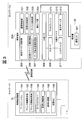
- FIG. 1 is a diagram illustrating an example of a schematic configuration of a device control system according to the first embodiment of the present invention.
- a device control system according to the first embodiment includes an information processing apparatus 10 connected to a LAN of a network 1, and a mobile terminal 20 and a multifunction device 30 connected to a LAN of a network 2 different from the network 1. Is done.
- the portable terminal 20 includes a communication interface that can be connected to the multifunction machine 30 and is connected to the information processing apparatus 10 of the network 1 by a wireless line such as a wireless LAN or a mobile line, or a communication line such as a wired line.
- a wireless line such as a wireless LAN or a mobile line
- a communication line such as a wired line.
- the network 2 is managed by an address system different from that of the network 1.
- the network 2 may be a network on the same floor as the network 1 or may be a remote network.
- the information processing apparatus 10 is a personal computer (PC), for example, and is not shown in FIG. 1, but includes a CPU, an input unit, a display unit, a memory, a storage unit, a communication unit, etc. as a hardware configuration. These hardwares are connected to each other via an internal bus.
- PC personal computer
- the CPU is a central processing unit that controls each unit in the information processing apparatus 10.
- the input unit is an operation device such as a keyboard or a mouse.
- the display unit is a display device such as a liquid crystal monitor.
- the memory is a storage device such as a RAM or a ROM.
- the communication unit is an interface for connecting to a communication line such as a wireless line such as a wireless LAN or a mobile line, or a wired line, and data can be transmitted / received via the communication line.
- the storage unit includes an operating system (hereinafter referred to as “OS”) which is software (not shown), an application 101, an address information setting unit 102, an address information search unit 109, a device driver 103, a virtualization control unit 104, a communication
- OS operating system
- the control unit 105 and the virtual NIC 106 are stored, and software related to other functions is stored. These software are read into the memory and operate according to the control of the CPU.
- the application 101 is a software program group for communicating with the mobile terminal 20 and the multifunction device 30 by instructing a data input / output request to the device driver 103.
- the address information setting unit 102 has a function of setting address information (IP address) for a virtual NIC 106 (described later).
- IP address was illustrated as address information, it is not limited to this, A MAC address, a device name, etc. may be sufficient. Furthermore, it may be a combination of these pieces of information.
- the address information search unit 109 has a function of searching for address information set in the communication I / F 301 of the multifunction device 30 and acquiring the address information of the multifunction device 30.
- the device driver 103 converts a data input / output request from the OS or application into data in a data format corresponding to the multifunction machine 30 (hereinafter referred to as “control command”), and sends the control command to the virtualization control unit 104. send. Furthermore, the device driver 103 notifies the application 101 of a response to the control command.
- the virtualization control unit 104 converts the control command (that is, data input / output request) sent from the device driver 103 into packet data (hereinafter referred to as “USB data”) conforming to the USB data format.
- USB data packet data
- the virtualization control unit 104 converts the USB data sent from the communication control unit 105 into a data format similar to that of the control command and sends the data to the device driver 103.
- the virtualization control unit 104 functions to simulate the same behavior as when the multifunction device 30 is directly connected (locally connected) to the information processing apparatus 10 in response to a data transmission / reception request to the multifunction device 30. (Hereinafter referred to as “virtualization control function”). With this virtualization control function, the information processing apparatus 10 can transmit and receive data by recognizing the MFP 30 as if it were locally connected.
- the communication control unit 105 performs a conversion process between the USB data sent from the virtualization control unit 104 and a network packet when communicating with the mobile terminal 20, and performs data transmission / reception between the mobile terminal 20 and the information processing apparatus 10. Control. Further, the communication control unit 105 controls connection and disconnection of a communication line (session) between the portable terminal 20 and the information processing apparatus 10 in response to a data transmission / reception request sent from the virtualization control unit 104.
- the virtual NIC 106 recognizes device information (individual identification information) of the communication I / F unit 204 (described later) of the mobile terminal 20 that is recognized as being connected to the information processing apparatus 10 through virtualization control. ) Based network adapter (software component).
- the virtual NIC 106 is generated based on information (USB descriptor information) such as a vendor ID, a product ID, and a serial number.
- the mobile terminal 20 is, for example, a device such as a mobile phone, a PDA, or a smartphone, and includes a CPU, a memory, a storage unit, a communication unit, and the like as a hardware configuration, although not shown in FIG.
- the CPU is a central processing unit that controls each unit in the mobile terminal 20.
- the memory is a RAM, a ROM, or the like.
- the communication unit is an interface for transmitting / receiving data via a wireless line such as a wireless LAN or a mobile line or a wired line, and can transmit / receive data to / from the information processing apparatus 10 of the network 1 via these lines. .
- the storage unit stores software (OS) (not shown), a communication control unit 201, a virtualization control unit 202, a device control unit 203, and other functions as software.
- OS software
- a communication control unit 201 a communication control unit 201
- a virtualization control unit 202 a virtualization control unit 202
- a device control unit 203 a device control unit 203
- the communication control unit 201 controls communication between the information processing apparatus 10 and the mobile terminal 20 by connecting to, for example, an Internet line or a mobile network (mobile phone line) (hereinafter referred to as “communication line”). Further, the communication control unit 201 converts the USB data sent from the virtualization control unit 202 into a network packet, and transmits the network packet to the information processing apparatus 10 via the communication line. Further, the communication control unit 201 responds to a data transmission / reception request sent from higher-layer software (such as the application 101 and the device driver 103) via the virtualization control unit 202, between the information processing apparatus 10 and the portable terminal 20. Control session connection and disconnection.
- higher-layer software such as the application 101 and the device driver 10
- the virtualization control unit 202 causes the communication I / F unit 204 (the USB device connected via the communication I / F unit 204) of the mobile terminal 20 to be recognized as if it is locally connected to the information processing apparatus 10. In order to control, virtualization control is performed according to (in conjunction with) a control request from the virtualization control unit 104 of the information processing apparatus 10.
- the device control unit 203 is software for controlling a device connected to the own device in accordance with the control of the virtualization control unit 202. In the present embodiment, it is software for controlling the USB device connected to the own apparatus, that is, the communication I / F unit 204.
- the communication I / F unit 204 is a conversion device that converts data formats transmitted and received by the interface (LAN) of the multifunction machine 30 and the interface (USB) of the portable terminal 20.
- the information processing apparatus 10 recognizes the communication I / F unit 204 as a USB device (a USB device that performs USB-LAN conversion).
- the function of the communication I / F unit 204 is determined according to the interface of the multifunction machine 30.
- the interface of the multifunction device 30 is USB
- the communication I / F unit 204 is a USB interface and is connected to the multifunction device 30 with a USB cable.
- the interface of the multifunction machine 30 is NFC (Near Field Communication)
- a USB device having an NFC interface such as a USB card reader is connected to the mobile terminal 20 as the communication I / F unit 204.
- the USB device connected to the portable terminal 20 becomes a USB-WLAN conversion adapter.
- the USB device connected to the portable terminal 20 is a USB-Bluetooth (registered trademark) conversion adapter.
- the communication I / F unit 204 is built in the mobile terminal 20.
- the form which attaches the communication I / F part 204 to the portable terminal 20 externally for example, the form which connects a USB-LAN conversion adapter to the portable terminal 20 may be sufficient.
- the OS detects the plug-in and recognizes it as a USB device.
- the multifunction device 30 is a multi-functional peripheral device having a scan function, a copy function, and a storage function in addition to the print function, and is a device connected to the network 2.
- a communication I / F 301 is provided as a communication interface, connected to the communication I / F unit 204 of the mobile terminal 20 via a LAN cable, and controlled from the information processing apparatus 10 via the mobile terminal 20.
- the multifunction machine 30 may be another device, and the communication interface is not limited to the LAN.
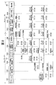
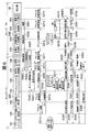
- FIG. 2 is a sequence diagram showing an operation when the information processing apparatus 10 of the network 1 and the multifunction machine 30 connected to the network 2 are virtualized and controlled via the mobile terminal 20 in the device control system shown in FIG. It is.
- the mobile terminal 20 is activated by connecting the cable connected to the communication I / F 301 of the MFP 30 connected via LAN in the remote network 2 to the communication I / F unit 204 of the mobile terminal 20.
- the mobile terminal 20 is activated by executing a predetermined connection operation (such as pressing a button) on the mobile terminal 20 after the cable is connected.
- a predetermined connection operation such as pressing a button
- the communication I / F unit 204 is recognized as being connected as a USB device, and the communication I / F unit 204 notifies the device control unit 203 of the connection of the USB device (step S101).
- the device control unit 203 sends a connection notification to the virtualization control unit 202 (step S102), and the virtualization control unit 202 sends a USB device connection notification to the information processing apparatus 10 via the communication control unit 201 (step S102). S103).
- the virtualization control unit 104 of the information processing apparatus 10 receives a connection notification from the mobile terminal 20, and requests device information from the mobile terminal 20 that is the transmission source of the connection notification (step S104).
- the virtualization control unit 202 of the mobile terminal 20 receives a request for device information from the information processing apparatus 10, and transmits the device information of the communication I / F unit 204 recognized as a USB device to the information processing apparatus 10 (step S105).
- information (USB descriptor information) such as a vendor ID, product ID, and serial number of the communication I / F unit 204 is transmitted as device information.
- the virtualization control unit 104 of the information processing apparatus 10 receives device information from the portable terminal 20 and sends this device information to the device driver 103 (step S106). Upon receiving the device information, the device driver 103 generates (adds) the virtual NIC 106 as a communication interface for connecting to the mobile terminal 20 and performing virtualization control (step S107).
- the address information search unit 109 confirms the presence confirmation and response of the multifunction device 30 to the broadcast address of the network 2 in order to acquire the address information set in the communication I / F 301 of the multifunction device 30. Send a command.
- this command is transmitted from the address information search unit 109 to the device driver 103 (step S108), from the device driver 103 to the virtualization control unit 104 (step S109), and from the virtualization control unit 104. It is transmitted to the virtual NIC 106 via the communication control unit 105 (step S110), and transmitted from the virtual NIC 106 to the portable terminal 20 (step S111).
- this command is received by the virtualization control unit 202 from the information processing apparatus 10 via the communication control unit 201, and is transmitted from the virtualization control unit 202 to the device control unit 203 (step S112).
- the data is transmitted from the unit 203 to the communication I / F unit 204 (step S113).
- the communication I / F unit 204 converts the USB data format command into a data format for transmission / reception via the LAN, and transmits the command to the communication I / F 301 of the multifunction machine 30 (step S114).
- the multifunction machine 30 transmits the address information set in the communication I / F 301 to the mobile terminal 20.
- the address information transmitted here is an IP address set in the communication I / F 301 of the multifunction machine 30, and may include a subnet mask and a default gateway.
- the address information is acquired by the address information search unit 109 along a path opposite to the transmission of the command.
- the address information search unit 109 creates an arbitrary IP address within the same segment as the address information set in the communication I / F 301 of the acquired multifunction device 30, and passes it to the address information setting unit 102 (step S115).
- the information processing apparatus 10 uses the address information setting unit 102 to set the address information (IP address) received from the address information search unit 109 in the virtual NIC 106 (step S116).
- the address information setting unit 102 sets address information in the virtual NIC 106 using a UI (not shown) of the information processing apparatus 10. Instead, the mobile terminal 20 transmits address information to the information processing apparatus 10 using the UI (not shown) of the mobile terminal 20, and the address information setting unit 102 of the information processing apparatus 10 addresses the virtual NIC 106. A mechanism for setting information may be used.
- the virtualization control unit 104 When the address information is set in the virtual NIC 106, the virtualization control unit 104 is instructed to perform virtualization control of the communication I / F unit 204 via the virtual NIC 106. Virtualization control is started by operating a UI screen (not shown) of the information processing apparatus 10. Instead of this, an instruction to start virtualization control may be sent to the information processing apparatus 10 by a predetermined operation of the mobile terminal 20.
- the application 101 transmits data to the device driver 103 (step S117), and the device driver 103 performs the virtualization control unit 104.
- the data is transmitted to (step S118).
- the virtualization control unit 104 transmits data to the virtual NIC 106 via the communication control unit 105 (step S119), and the virtual NIC 106 transmits data to the portable terminal 20 (step S120).
- the virtualization control unit 202 receives data from the information processing apparatus 10 via the communication control unit 201, and the virtualization control unit 202 transmits data to the device control unit 203 (step S121).
- the device control unit 203 transmits data to the communication I / F unit 204 (step S122), the communication I / F unit 204 converts the data in the USB format into a format for transmitting and receiving via the LAN, and the multifunction device 30.
- the data converted into the communication I / F 301 is transmitted (step S123).
- the multifunction device 30 executes operations such as printing and scanning in response to the received data, and transmits status data and scan data to the portable terminal 20. These data are acquired by the application 101 along a path opposite to the transmission of the data.
- the information processing apparatus 10 transmits / receives data to / from the mobile terminal 20 via the virtual NIC 106, and virtualizes the communication I / F unit 204 of the mobile terminal 20. As a result, the information processing apparatus 10 recognizes and controls the same state as when the MFP 30 connected to the communication I / F unit 204 is locally connected.
- a predetermined end operation for example, pressing an end button or an operation using a UI screen
- the virtualization control unit 104 of the information processing apparatus 10 transmits a control end request to the information processing apparatus 10 via the communication control unit 201 (step S124).
- the virtualization control end operation can also be executed from the information processing apparatus 10.
- the information processing apparatus 10 sends a control end request received from the mobile terminal 20 to the device driver 103, and the device driver 103 sends a control end request to the application 101 (step S125).
- the application 101 Upon receiving the control end request, the application 101 instructs the virtualization control unit 104 to end the virtualization control of the communication I / F unit 204 of the mobile terminal 20, and the virtualization control unit 104 displays the communication I / F unit 204. The virtualization control of is terminated.
- the application 101 instructs the device driver 103 to end the virtual NIC 106 (step S126), and the device driver 103 ends the virtual NIC 106 (step S127).
- the communication I / F unit 204 of the mobile terminal 20 is an interface other than a LAN
- necessary setting contents are set on the information processing apparatus 10 side according to the device.
- the setting may be made according to the device, such as setting using a UI on the mobile terminal 20 side or a communication application (both not shown).
- the mobile terminal 20 when data communication is performed between the information processing apparatus 10 of the network 1 and the MFP 30 of the network 2, the mobile terminal 20 is prepared on the network 2 side. Then, the information processing apparatus 10 and the mobile terminal 20 of the network 1 are connected by a communication line, and the MFP 30 is connected to the communication I / F unit of the mobile terminal 20, so that the information processing apparatus 10 communicates with the mobile terminal 20. It becomes possible to operate (virtualization control) the multi-function device 30 via the I / F unit 204.
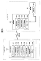
- FIG. 3 is a block diagram showing an example of a schematic configuration of a device control system according to the second embodiment of the present invention.
- the information processing apparatus 10 controls the internal device (input device, display device) of the mobile terminal 20 to be virtualized, so that an operation from the internal device of the mobile terminal 20 is performed. Send to.
- the information processing apparatus 10 is characterized in that the multifunction machine 30 is remotely operated.
- the device control system in FIG. 3 includes an information processing apparatus 10, a portable terminal 20A, and a multifunction device 30, and the configuration of the portable terminal 20A is different from the device control system shown in FIG. Since other connection configurations and components are the same as those in FIG. 1, the same components as those shown in FIG. 1 are denoted by the same reference numerals, description thereof is omitted, and only different points will be described.
- the mobile terminal 20A includes a virtual device control unit 205 and an internal device 213 in addition to the configuration of the mobile terminal 20 of FIG.
- the internal device 213 (input / output device) includes an input device 211 and a display device 212 that are used as a user interface, and is connected to each other via an internal bus 208 by an input I / F 209 and a display I / F 210, respectively.
- the input device 211 is, for example, a software keyboard that implements functions such as a keyboard, a numeric keypad, and a mouse with software.
- the display device 212 is, for example, a liquid crystal monitor.
- the virtual device control unit 205 includes virtual device identification information 206 and a data format conversion processing unit 207.
- the virtual device identification information 206 is information for causing the information processing apparatus 10 to recognize that the input device 211 and the display device 212 of the mobile terminal 20A are USB devices connected to the own apparatus.
- the data format conversion processing unit 207 includes packet data (USB data) that conforms to the USB data format (first data format) transmitted / received to / from the virtualization control unit 202, an input I / F 209, and a display I / F 210.
- the data is converted into data in a data format (second data format) that can be processed by the internal device 213 that transmits / receives the data.
- data is transmitted and received without performing the conversion process.
- the input device 211 and the display device 212 are internal devices of the mobile terminal 20A, and do not have individual identification information (device information) such as a vendor ID, a product ID, and descriptor information unlike a USB device connected by a USB interface. Therefore, information corresponding to these is created in a pseudo manner, assigned to the input device 211 and the display device 212 as virtual device identification information 206, and stored in the virtual device control unit 205 or the like.
- device information such as a vendor ID, a product ID, and descriptor information unlike a USB device connected by a USB interface. Therefore, information corresponding to these is created in a pseudo manner, assigned to the input device 211 and the display device 212 as virtual device identification information 206, and stored in the virtual device control unit 205 or the like.
- the USB descriptor that identifies the HID class is sent to the virtualization control unit 202 as the virtual device identification information 206 related to the input device 211 such as a keyboard and a mouse. Further, the data format conversion processing unit 207 converts the input data input from the input device 211 into USB data of the HID class and sends it to the virtualization control unit 202 via the input I / F 209.
- the USB descriptor identifying the vendor specific information is sent to the virtualization control unit 202 as the virtual device identification information 206 related to the display device 212 such as a display.
- the data format conversion processing unit 207 converts the USB data sent from the virtualization control unit 202 into the data format of the display device 212 and sends it to the display device 212 via the display I / F 210.
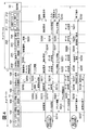
- FIG. 4 is a sequence diagram showing the operation of virtualization control in the device control system shown in FIG.
- the information processing apparatus 10 recognizes the communication I / F unit 204 as a USB device, and the virtual NIC 106 is generated as a communication interface for connecting to the mobile terminal 20A and performing virtualization control. Since the process (steps S201 to S207) is the same as the sequence from step S101 to step S107 in FIG. 2 described in the first embodiment, description thereof is omitted.
- the user operates the mobile terminal 20A to display an operation screen on the display device 212.
- a connection operation using the input device 211 for example, pressing of a connection button
- the internal device 213 requests the virtual device control unit 205 to connect the internal device 213 (step S209).
- the virtual device control unit 205 When detecting the connection request, the virtual device control unit 205 sends a connection request for the internal device 213 including the virtual device identification information 206 of the display device 212 and the input device 211 to the virtualization control unit 202 (step S210).
- the virtualization control unit 202 Upon receiving the connection request including the virtual device identification information 206, the virtualization control unit 202 transmits a connection request to the information processing apparatus 10 via the communication control unit 201 (step S211).
- the information processing apparatus 10 sends the connection request received from the mobile terminal 20A to the virtualization control unit 104 via the virtual NIC 106, and the virtualization control unit 104 sends the connection request to the device driver 103 (step S212).
- the device driver 103 sends a connection request for the internal device 213 of the mobile terminal 20A to the application 101 (step S213).
- the application 101 instructs the virtualization control unit 104 to start virtualization control of the internal device 213 corresponding to the virtual device identification information 206 included in the connection request, and the virtualization control unit 104 The virtualization control of the internal device 213 is started.
- the application 101 transmits screen data to the device driver 103 (step S214, the device driver 103 transmits screen data to the virtualization control unit 104 (step S215). Thereafter, the virtualization control unit 104 transmits screen data to the virtual NIC 106 via the communication control unit 105 (step S216), and the virtual NIC 106 transmits the screen data to the mobile terminal 20A.
- the virtualization control unit 202 receives screen data from the information processing apparatus 10 via the communication control unit 201, and the virtualization control unit 202 transmits screen data to the virtual device control unit 205 (step S217).
- the virtual device control unit 205 transmits screen data to the display device 212 via the display I / F 210 connected to the internal bus 208 (step S218), and the screen is displayed on the display device 212.
- the information processing apparatus 10 starts virtualization control of the internal device 213 of the mobile terminal 20A and sends the input data input from the input device 211 to the information processing apparatus 10, the reverse path to the transmission of the screen data
- the input data received via the input I / F 209 connected to the internal bus 208 is transferred to the application 101 via the virtual device control unit 205, the virtualization control unit 202, the virtualization control unit 104, and the device driver 103. Sent to.
- the data format conversion processing unit 207 of the virtual device control unit 205 converts the USB data sent from the virtualization control unit 202 into the data format (third data format) of the display device 212. Then, the data is transmitted via the display I / F, the data input by the operation of the input device 211 is received via the input I / F, and the input data is converted into USB data (fourth data format). To the virtualization control unit 202.
- screen data (for example, an image displayed on a liquid crystal panel connected to the information processing apparatus 10) sent from the information processing apparatus 10 is displayed on the display device 212 of the mobile terminal 20A. Further, by operating the input device 211, it is possible to perform an input operation similar to that of a keyboard or a numeric keypad on the information processing apparatus 10.
- step S2128 it is possible to operate the information processing apparatus 10 by operating the input device 211 while checking the display device 212 on the portable terminal 20A side.
- the user operates the input device 211 while confirming the display device 212 of the mobile terminal 20A, and inputs the address information (IP address) of the virtual NIC 106 generated by the information processing apparatus 10 (step S219).
- IP address When the address information (IP address) is input from the input device 211, this address information is sent to the virtual device control unit 205 (step S220).
- the virtual device control unit 205 converts the data format and sends it to the virtualization control unit 202 (step S221).
- the virtualization control unit 202 transmits this address information to the information processing apparatus 10 via the communication control unit 201 (step S222).
- the information processing apparatus 10 sends the address information received from the mobile terminal 20A to the virtualization control unit 104, and the virtualization control unit 104 sends the address information to the address information setting unit 102 (step S223).
- the address information setting unit 102 sets address information (IP address) of the same segment as the network 2 to which the multifunction machine 30 is connected to the virtual NIC 106 based on the address information (step S224).
- IP address IP address
- the IP addresses of the multifunction machine 30 and the virtual NIC 106 are set to the same segment, and the information processing apparatus 10 can transmit / receive data to / from the multifunction machine 30 via the portable terminal 20B.
- step S225 to S231 Regarding the data transmission / reception process (steps S225 to S231) between the information processing apparatus 10 and the multifunction machine 30 performed via the portable terminal 20A, from step S117 to step S123 of FIG. 2 described in the first embodiment. Since this is the same as the sequence, the description is omitted.
- the portable terminal 20A is operated to display the operation screen on the display device 212, and an end operation (for example, pressing of the end button) by the input device 211 is executed (step) S232).
- an end operation for example, pressing of the end button
- a control end request for the internal device 213 is sent from the internal device 213 to the virtual device control unit 205 (step S233). Note that the end operation can also be executed from the information processing apparatus 10.
- the virtual device control unit 205 sends a control end request for the internal device 213 to the virtualization control unit 202 (step S234), and the virtualization control unit 202 sends this control end notification to the information processing apparatus 10 via the communication control unit 201. Transmit (step S235).
- the information processing apparatus 10 sends the control end notification received from the mobile terminal 20A to the device driver 103, and the device driver 103 sends this control end request to the application 101 (step S236).
- the application 101 When the application 101 receives the control end request, the application 101 instructs the virtualization control unit 104 to end the virtualization control of the communication I / F unit 204 of the mobile terminal 20 ⁇ / b> A.
- the virtualization control is terminated (step S237).
- the application 101 instructs the device driver 103 to end the virtual NIC 106, and the device driver 103 ends the virtual NIC 106 (step S238).
- the display device 212 switches to the display state before the virtualization control.
- a display device liquid crystal monitor
- a software keyboard is controlled as an input device.
- other internal devices in the mobile terminal are virtualized. It is also possible to control.
- the information processing apparatus 10 performs virtualization control using the NFC card reader built in the mobile terminal 20A as a USB device (internal device). Let As a result, the information processing apparatus 10 and the multifunction device 30 can perform data communication via the NFC communication interface.
- NFC Near Field Communication
- the camera function built in the mobile terminal 20A on the network 2 side is changed to the virtual device identification information 206.
- USB camera To be recognized as a USB device (hereinafter referred to as “USB camera”).
- the internal device 213 of the mobile terminal 20A is virtualized by the information processing apparatus 10 to display the display screen of the information processing apparatus 10 on the display device 212 of the mobile terminal 20A and
- the information processing apparatus 10 can be operated using the input device 211 of the terminal 20A.
- FIG. 5 is a block diagram showing an example of a schematic configuration of a device control system according to the third embodiment of the present invention.
- the third embodiment of the present invention is characterized in that the amount of network packets transmitted and received between the information processing apparatus 10B and the portable terminal 20B is reduced.
- the device control system in FIG. 5 includes an information processing apparatus 10B, a portable terminal 20B, and a multifunction device 30, and the configurations of the information processing apparatus 10B and the portable terminal 20B are different from the device control system illustrated in FIG. .
- the filter driver 108 stores in advance a transmission pattern of a periodic polling packet that is transmitted in order to check the state of the device. Upon receiving the transfer request from the device driver 103, the filter driver 108 generates pseudo response information (hereinafter referred to as “pseudo response”) for the transfer request. Accordingly, the filter driver 108 sends a pseudo response according to the transmission pattern until a notification indicating a change in the operation state is sent from the communication I / F unit 204 of the mobile terminal 20B recognized as a USB device.
- pseudo response information hereinafter referred to as “pseudo response”
- the mobile terminal 20B includes an automatic communication control unit 220 in addition to the configuration of the mobile terminal 20 of FIG.
- the automatic communication control unit 220 stores a polling transmission pattern corresponding to the transmission pattern of the filter driver 108 in advance.
- the automatic communication control unit 220 performs polling on the communication I / F unit 204 according to this transmission pattern, and repeats polling until a change in the operation state of the communication I / F unit 204 is detected. Then, when detecting a change in the operation state of the communication I / F unit 204, the automatic communication control unit 220 notifies the information processing apparatus 10B via the communication control unit 201 of information indicating this detection (state change notification).
- FIG. 6 is a sequence diagram showing the operation of virtualization control in the device control system shown in FIG. Note that the filter driver 108 of the information processing apparatus 10B and the automatic communication control unit 220 of the portable terminal 20B will be described assuming that a transmission pattern of a periodic polling packet to be transmitted in order to check the device state is stored in advance. .
- the mobile terminal 20B is operated to cause the information processing apparatus 10B to recognize the communication I / F unit 204 as a USB device, and the virtual NIC 106 is generated as a communication interface for virtualizing control by connecting to the mobile terminal 20B.
- the process until the address information is set in the virtual NIC 106 (steps S301 to S316) is the same as the sequence from step S101 to step S116 in FIG. 2 described in the first embodiment, and thus the description thereof is omitted.
- the information processing apparatus 10B causes the filter driver 108 to start polling when a network session for virtualization control is started with the mobile terminal 20B. For example, when the device driver 103 issues a USB interrupt transfer communication request, the filter driver 108 generates a pseudo response to the communication request and returns it to the device driver 103 according to a polling packet transmission pattern stored in advance ( Step S317).
- the device driver 103 When the device driver 103 receives the pseudo response, the device driver 103 recognizes that the response from the communication I / F unit 204 of the mobile terminal 20B has been received by periodic polling, and issues the next communication request. This is repeated until a state change notification (described later) is received from the communication I / F unit 204 of the mobile terminal 20B.
- the automatic communication control unit 220 sends a polling packet (for example, USB interrupt transfer) to the device control unit 203. Communication request) is sent (step S318).
- the device control unit 203 transmits a polling packet to the communication I / F unit 204 (step S319).
- the processes in steps S318 to S319 are repeated until a change in the operation state of the communication I / F unit 204 is detected.
- step S320 When the operation state of the communication I / F unit 204 changes, the change of the operation state is notified to the device control unit 203 (step S320). Next, the device control unit 203 sends this notification (hereinafter referred to as “state change notification”) to the automatic communication control unit 220 (step S321). The automatic communication control unit 220 transmits the received state change notification to the information processing apparatus 10B via the communication control unit 201 (step S322).
- the virtual NIC 106 of the information processing apparatus 10B sends the state change notification received from the mobile terminal 20B to the virtualization control unit 104 (step S323).
- the virtualization control unit 104 sends this state change notification to the filter driver 108 (step S324).
- the filter driver 108 sends this state change notification to the application 101 (step S325).
- the information processing apparatus 10B can transmit and receive data to and from the multifunction machine 30 via the portable terminal 20B.
- step S326 to S332 With respect to the data transmission / reception process (steps S326 to S332) between the information processing apparatus 10B and the multifunction device 30 performed via the portable terminal 20B, the processes from step S117 to step S123 of FIG. 2 described in the first embodiment are performed. Since this is the same as the sequence, the description is omitted.
- step S333 to S337 the process for ending the virtualization control by the information processing apparatus 10B (steps S333 to S337) is the same as the sequence from step S124 to step S127 of FIG. 2 described in the first embodiment, and therefore will be described. Is omitted.
- the polling packet periodically transmitted from the device driver 103 of the information processing apparatus 10B to the mobile terminal 20B and the response of the polling packet are not issued on the network every time. Therefore, the amount of network packets issued between the information processing apparatus 10B and the mobile terminal 20B can be suppressed.
- each of the information processing apparatus, the portable terminal, and the multifunction peripheral is configured as one unit, but the number is not limited to the example illustrated.
- the multifunction machine 30 is not limited to an office device, and may be various embedded devices, mobile phones, or mobile terminal devices.
- the aspect of the present invention is also achieved by a computer of a system or apparatus (or a device such as a CPU or MPU) that reads and executes a program stored in a storage device in order to realize the functions of the above-described embodiments,
- the steps are also achieved by a method executed by a computer of a system or apparatus by reading and executing a program stored in a storage device to realize the functions of the above-described embodiments, for example.
- the program is provided to the computer, for example, via a network or from various recording media that serve as storage devices (eg, computer-readable media).
Landscapes
- Engineering & Computer Science (AREA)
- Theoretical Computer Science (AREA)
- Physics & Mathematics (AREA)
- Human Computer Interaction (AREA)
- General Engineering & Computer Science (AREA)
- General Physics & Mathematics (AREA)
- Mathematical Physics (AREA)
- Computer Networks & Wireless Communication (AREA)
- Computer And Data Communications (AREA)
Priority Applications (1)
| Application Number | Priority Date | Filing Date | Title |
|---|---|---|---|
| US14/752,298 US9395941B2 (en) | 2012-12-28 | 2015-06-26 | Information processing apparatus, portable terminal, and control method therefor |
Applications Claiming Priority (4)
| Application Number | Priority Date | Filing Date | Title |
|---|---|---|---|
| JP2012-288309 | 2012-12-28 | ||
| JP2012288309 | 2012-12-28 | ||
| JP2013247802A JP6212367B2 (ja) | 2012-12-28 | 2013-11-29 | 情報処理装置、携帯端末、デバイス制御システム、およびその制御方法 |
| JP2013-247802 | 2013-11-29 |
Related Child Applications (1)
| Application Number | Title | Priority Date | Filing Date |
|---|---|---|---|
| US14/752,298 Continuation US9395941B2 (en) | 2012-12-28 | 2015-06-26 | Information processing apparatus, portable terminal, and control method therefor |
Publications (1)
| Publication Number | Publication Date |
|---|---|
| WO2014104397A1 true WO2014104397A1 (ja) | 2014-07-03 |
Family
ID=51021451
Family Applications (1)
| Application Number | Title | Priority Date | Filing Date |
|---|---|---|---|
| PCT/JP2013/085325 Ceased WO2014104397A1 (ja) | 2012-12-28 | 2013-12-25 | 情報処理装置、携帯端末、デバイス制御システム、およびその制御方法 |
Country Status (3)
| Country | Link |
|---|---|
| US (1) | US9395941B2 (enExample) |
| JP (1) | JP6212367B2 (enExample) |
| WO (1) | WO2014104397A1 (enExample) |
Families Citing this family (2)
| Publication number | Priority date | Publication date | Assignee | Title |
|---|---|---|---|---|
| JP6311688B2 (ja) * | 2015-10-22 | 2018-04-18 | コニカミノルタ株式会社 | 一括設定システム、携帯情報装置、連携設定方法および連携設定プログラム |
| US10459855B2 (en) | 2016-07-01 | 2019-10-29 | Intel Corporation | Load reduced nonvolatile memory interface |
Citations (3)
| Publication number | Priority date | Publication date | Assignee | Title |
|---|---|---|---|---|
| JP2010218347A (ja) * | 2009-03-18 | 2010-09-30 | Nec Corp | シンクライアントサーバシステム及びusbデバイスのドライバの管理方法 |
| JP2011129111A (ja) * | 2009-11-18 | 2011-06-30 | Canon Imaging Systems Inc | クライアント装置、デバイス制御方法、およびデバイス制御システム |
| JP2012138694A (ja) * | 2010-12-24 | 2012-07-19 | Canon Imaging Systems Inc | クライアント装置、デバイス制御方法、およびデバイス制御システム |
Family Cites Families (8)
| Publication number | Priority date | Publication date | Assignee | Title |
|---|---|---|---|---|
| EP0567217B1 (en) | 1992-04-20 | 2001-10-24 | 3Com Corporation | System of extending network resources to remote networks |
| EP1571562B1 (de) * | 2004-03-03 | 2017-11-01 | Swisscom AG | Verfahren, mit welchem eine Telekommunikationsdienstleistung mittels einer elektronischen Adresse beansprucht werden kann |
| JP2008210115A (ja) * | 2007-02-26 | 2008-09-11 | Nec Corp | リモートコンピュータ上でローカル端末のusbデバイスを操作するシステム、その方法及びそのプログラム |
| JP2009098977A (ja) * | 2007-10-17 | 2009-05-07 | Vision Arts Kk | 周辺機器接続システム |
| JP2010117855A (ja) * | 2008-11-12 | 2010-05-27 | Hitachi Ltd | シンクライアントシステム、シンクライアントシステム構成方法、シンクライアントシステムを構成する周辺機器接続装置および計算機 |
| US8683554B2 (en) * | 2009-03-27 | 2014-03-25 | Wavemarket, Inc. | System and method for managing third party application program access to user information via a native application program interface (API) |
| CN102597974B (zh) | 2009-11-04 | 2016-02-10 | 佳能成像系统株式会社 | 装置控制设备、客户端设备、装置控制方法和装置控制系统 |
| JP6216510B2 (ja) | 2012-12-27 | 2017-10-18 | キヤノンイメージングシステムズ株式会社 | 携帯端末、携帯端末の制御方法、およびデバイス制御システム |
-
2013
- 2013-11-29 JP JP2013247802A patent/JP6212367B2/ja not_active Expired - Fee Related
- 2013-12-25 WO PCT/JP2013/085325 patent/WO2014104397A1/ja not_active Ceased
-
2015
- 2015-06-26 US US14/752,298 patent/US9395941B2/en not_active Expired - Fee Related
Patent Citations (3)
| Publication number | Priority date | Publication date | Assignee | Title |
|---|---|---|---|---|
| JP2010218347A (ja) * | 2009-03-18 | 2010-09-30 | Nec Corp | シンクライアントサーバシステム及びusbデバイスのドライバの管理方法 |
| JP2011129111A (ja) * | 2009-11-18 | 2011-06-30 | Canon Imaging Systems Inc | クライアント装置、デバイス制御方法、およびデバイス制御システム |
| JP2012138694A (ja) * | 2010-12-24 | 2012-07-19 | Canon Imaging Systems Inc | クライアント装置、デバイス制御方法、およびデバイス制御システム |
Also Published As
| Publication number | Publication date |
|---|---|
| US9395941B2 (en) | 2016-07-19 |
| JP6212367B2 (ja) | 2017-10-11 |
| US20150293730A1 (en) | 2015-10-15 |
| JP2014142920A (ja) | 2014-08-07 |
Similar Documents
| Publication | Publication Date | Title |
|---|---|---|
| JP6098423B2 (ja) | 端末装置とプリンタ | |
| US10067724B2 (en) | Image forming apparatus with selectable service configuration, image forming system including same, and method for selective image formation | |
| JP6069939B2 (ja) | 無線通信機器、通信設定方法および通信設定プログラム | |
| CN105848191B (zh) | 通信装置及控制方法 | |
| JP2012029164A (ja) | 携帯端末及び装置管理方法 | |
| US9264460B2 (en) | Method, apparatus, and system for executing a job in cooperation with a server | |
| JP2013250760A (ja) | 中継サーバ | |
| JP2012253514A (ja) | 画像入力システム、サーバ装置、サーバ装置の制御方法、及び制御プログラム | |
| CA2865725A1 (en) | Information processing system, information processing method, mobile phone, server, and control method and control program thereof | |
| JP2011238006A (ja) | 画像形成システムおよびサーバー装置 | |
| JP7071575B2 (ja) | 情報処理装置及びその制御方法、並びにプログラム | |
| JP2014011582A (ja) | 画像処理装置及びその制御方法とプログラム | |
| JP6341786B2 (ja) | 印刷装置、印刷装置の制御方法、プログラム及び印刷システム | |
| JP6212367B2 (ja) | 情報処理装置、携帯端末、デバイス制御システム、およびその制御方法 | |
| JP5932244B2 (ja) | サーバー装置、情報処理装置、それらの制御方法、及び制御プログラム | |
| US10218816B2 (en) | Information processing system, information processing method, server, and control method and control program of server | |
| JP6216510B2 (ja) | 携帯端末、携帯端末の制御方法、およびデバイス制御システム | |
| JP5887835B2 (ja) | 印刷システム、印刷装置、及びプログラム | |
| JP4900576B2 (ja) | プログラム、記憶媒体および画像処理方法 | |
| JP2017182303A (ja) | 画像形成システム及び画像形成装置 | |
| WO2021181656A1 (ja) | データ処理装置、データ処理方法、及びプログラム | |
| JP2014154058A (ja) | 画像処理装置 | |
| JP5108571B2 (ja) | 機器、データ転送システム、データ転送方法、プログラムおよび記録媒体 | |
| JP2023165196A (ja) | 情報処理システム、情報処理装置、情報処理方法、及びプログラム | |
| JP2018190046A (ja) | デバイス制御装置、デバイス制御方法、およびプログラム |
Legal Events
| Date | Code | Title | Description |
|---|---|---|---|
| 121 | Ep: the epo has been informed by wipo that ep was designated in this application |
Ref document number: 13869482 Country of ref document: EP Kind code of ref document: A1 |
|
| NENP | Non-entry into the national phase |
Ref country code: DE |
|
| 122 | Ep: pct application non-entry in european phase |
Ref document number: 13869482 Country of ref document: EP Kind code of ref document: A1 |