WO2014104397A1 - 情報処理装置、携帯端末、デバイス制御システム、およびその制御方法 - Google Patents
情報処理装置、携帯端末、デバイス制御システム、およびその制御方法 Download PDFInfo
- Publication number
- WO2014104397A1 WO2014104397A1 PCT/JP2013/085325 JP2013085325W WO2014104397A1 WO 2014104397 A1 WO2014104397 A1 WO 2014104397A1 JP 2013085325 W JP2013085325 W JP 2013085325W WO 2014104397 A1 WO2014104397 A1 WO 2014104397A1
- Authority
- WO
- WIPO (PCT)
- Prior art keywords
- processing apparatus
- information processing
- information
- interface
- mobile terminal
- Prior art date
Links
Images

Classifications
-
- G—PHYSICS
- G06—COMPUTING; CALCULATING OR COUNTING
- G06F—ELECTRIC DIGITAL DATA PROCESSING
- G06F3/00—Input arrangements for transferring data to be processed into a form capable of being handled by the computer; Output arrangements for transferring data from processing unit to output unit, e.g. interface arrangements
- G06F3/12—Digital output to print unit, e.g. line printer, chain printer
- G06F3/1201—Dedicated interfaces to print systems
- G06F3/1223—Dedicated interfaces to print systems specifically adapted to use a particular technique
- G06F3/1229—Printer resources management or printer maintenance, e.g. device status, power levels
- G06F3/1231—Device related settings, e.g. IP address, Name, Identification
-
- G—PHYSICS
- G06—COMPUTING; CALCULATING OR COUNTING
- G06F—ELECTRIC DIGITAL DATA PROCESSING
- G06F3/00—Input arrangements for transferring data to be processed into a form capable of being handled by the computer; Output arrangements for transferring data from processing unit to output unit, e.g. interface arrangements
- G06F3/12—Digital output to print unit, e.g. line printer, chain printer
- G06F3/1201—Dedicated interfaces to print systems
- G06F3/1202—Dedicated interfaces to print systems specifically adapted to achieve a particular effect
- G06F3/1218—Reducing or saving of used resources, e.g. avoiding waste of consumables or improving usage of hardware resources
- G06F3/122—Reducing or saving of used resources, e.g. avoiding waste of consumables or improving usage of hardware resources with regard to computing resources, e.g. memory, CPU
-
- G—PHYSICS
- G06—COMPUTING; CALCULATING OR COUNTING
- G06F—ELECTRIC DIGITAL DATA PROCESSING
- G06F3/00—Input arrangements for transferring data to be processed into a form capable of being handled by the computer; Output arrangements for transferring data from processing unit to output unit, e.g. interface arrangements
- G06F3/12—Digital output to print unit, e.g. line printer, chain printer
- G06F3/1201—Dedicated interfaces to print systems
- G06F3/1223—Dedicated interfaces to print systems specifically adapted to use a particular technique
- G06F3/1229—Printer resources management or printer maintenance, e.g. device status, power levels
- G06F3/1232—Transmitting printer device capabilities, e.g. upon request or periodically
-
- G—PHYSICS
- G06—COMPUTING; CALCULATING OR COUNTING
- G06F—ELECTRIC DIGITAL DATA PROCESSING
- G06F3/00—Input arrangements for transferring data to be processed into a form capable of being handled by the computer; Output arrangements for transferring data from processing unit to output unit, e.g. interface arrangements
- G06F3/12—Digital output to print unit, e.g. line printer, chain printer
- G06F3/1201—Dedicated interfaces to print systems
- G06F3/1223—Dedicated interfaces to print systems specifically adapted to use a particular technique
- G06F3/1236—Connection management
-
- G—PHYSICS
- G06—COMPUTING; CALCULATING OR COUNTING
- G06F—ELECTRIC DIGITAL DATA PROCESSING
- G06F3/00—Input arrangements for transferring data to be processed into a form capable of being handled by the computer; Output arrangements for transferring data from processing unit to output unit, e.g. interface arrangements
- G06F3/12—Digital output to print unit, e.g. line printer, chain printer
- G06F3/1201—Dedicated interfaces to print systems
- G06F3/1278—Dedicated interfaces to print systems specifically adapted to adopt a particular infrastructure
- G06F3/1285—Remote printer device, e.g. being remote from client or server
-
- G—PHYSICS
- G06—COMPUTING; CALCULATING OR COUNTING
- G06F—ELECTRIC DIGITAL DATA PROCESSING
- G06F3/00—Input arrangements for transferring data to be processed into a form capable of being handled by the computer; Output arrangements for transferring data from processing unit to output unit, e.g. interface arrangements
- G06F3/12—Digital output to print unit, e.g. line printer, chain printer
- G06F3/1201—Dedicated interfaces to print systems
- G06F3/1278—Dedicated interfaces to print systems specifically adapted to adopt a particular infrastructure
- G06F3/1292—Mobile client, e.g. wireless printing
-
- G—PHYSICS
- G06—COMPUTING; CALCULATING OR COUNTING
- G06F—ELECTRIC DIGITAL DATA PROCESSING
- G06F3/00—Input arrangements for transferring data to be processed into a form capable of being handled by the computer; Output arrangements for transferring data from processing unit to output unit, e.g. interface arrangements
- G06F3/12—Digital output to print unit, e.g. line printer, chain printer
- G06F3/1201—Dedicated interfaces to print systems
- G06F3/1202—Dedicated interfaces to print systems specifically adapted to achieve a particular effect
- G06F3/1222—Increasing security of the print job
-
- G—PHYSICS
- G06—COMPUTING; CALCULATING OR COUNTING
- G06F—ELECTRIC DIGITAL DATA PROCESSING
- G06F3/00—Input arrangements for transferring data to be processed into a form capable of being handled by the computer; Output arrangements for transferring data from processing unit to output unit, e.g. interface arrangements
- G06F3/12—Digital output to print unit, e.g. line printer, chain printer
- G06F3/1201—Dedicated interfaces to print systems
- G06F3/1278—Dedicated interfaces to print systems specifically adapted to adopt a particular infrastructure
- G06F3/1285—Remote printer device, e.g. being remote from client or server
- G06F3/1289—Remote printer device, e.g. being remote from client or server in server-client-printer device configuration, e.g. the server does not see the printer
Definitions
- the present invention relates to an information processing apparatus, a mobile terminal, a device control system, and a control method for controlling a device such as a printer via a network.
- VPN virtual private network
- devices PCs, peripheral devices
- Remote desktop technology is known.
- VPN is connected via a communication line such as an Internet line or a mobile network (cell phone line), for example, in the same way that remote networks are connected with a LAN while maintaining confidentiality, and data communication is performed. Enable.
- a plurality of peripheral devices are aggregated via a hub device and connected to a mobile terminal such as a smartphone, and a remote desktop environment is connected by a remote server connected to the mobile terminal via a network.
- a hub device and connected to a mobile terminal such as a smartphone
- a remote desktop environment is connected by a remote server connected to the mobile terminal via a network.
- the present invention reduces the effort and cost until introduction, and allows the information processing apparatus to remotely control the device via the mobile terminal without concentrating the load on the mobile terminal, the mobile terminal,
- An object is to provide a device control system and a control method thereof.
- an information processing apparatus is an information processing apparatus connected to a mobile terminal via a network, and acquires individual identification information possessed by the first interface means of the mobile terminal, A virtual interface generating unit that generates a virtual interface based on the individual identification information and a device connected to the second interface unit of the portable terminal via the generated virtual interface are simulated as being directly connected And a virtualization control means.
- a portable terminal comprises a first interface means for transmitting and receiving data in a first data format and a second interface means for transmitting and receiving data in a second data format.
- a terminal that transmits individual identification information of the first interface unit to an information processing apparatus connected via a network, and the virtual information generated by the information processing apparatus based on the individual identification information
- Virtualization control means for simulating a device connected to the second interface means to be directly connected; and when the information processing apparatus simulates the device by the virtualization control means, the first And a data format conversion means for mutually converting the data format and the second data format. And butterflies.
- the information processing apparatus can remotely operate the device via the mobile terminal without concentrating the load on the mobile terminal.
- FIG. 4 is a sequence diagram showing an operation of virtualization control in the device control system shown in FIG. 3. It is a block diagram which shows an example of schematic structure of the device control system by the 3rd Embodiment of this invention. It is a sequence diagram which shows the operation
- FIG. 1 is a diagram illustrating an example of a schematic configuration of a device control system according to the first embodiment of the present invention.
- a device control system according to the first embodiment includes an information processing apparatus 10 connected to a LAN of a network 1, and a mobile terminal 20 and a multifunction device 30 connected to a LAN of a network 2 different from the network 1. Is done.
- the portable terminal 20 includes a communication interface that can be connected to the multifunction machine 30 and is connected to the information processing apparatus 10 of the network 1 by a wireless line such as a wireless LAN or a mobile line, or a communication line such as a wired line.
- a wireless line such as a wireless LAN or a mobile line
- a communication line such as a wired line.
- the network 2 is managed by an address system different from that of the network 1.
- the network 2 may be a network on the same floor as the network 1 or may be a remote network.
- the information processing apparatus 10 is a personal computer (PC), for example, and is not shown in FIG. 1, but includes a CPU, an input unit, a display unit, a memory, a storage unit, a communication unit, etc. as a hardware configuration. These hardwares are connected to each other via an internal bus.
- PC personal computer
- the CPU is a central processing unit that controls each unit in the information processing apparatus 10.
- the input unit is an operation device such as a keyboard or a mouse.
- the display unit is a display device such as a liquid crystal monitor.
- the memory is a storage device such as a RAM or a ROM.
- the communication unit is an interface for connecting to a communication line such as a wireless line such as a wireless LAN or a mobile line, or a wired line, and data can be transmitted / received via the communication line.
- the storage unit includes an operating system (hereinafter referred to as “OS”) which is software (not shown), an application 101, an address information setting unit 102, an address information search unit 109, a device driver 103, a virtualization control unit 104, a communication
- OS operating system
- the control unit 105 and the virtual NIC 106 are stored, and software related to other functions is stored. These software are read into the memory and operate according to the control of the CPU.
- the application 101 is a software program group for communicating with the mobile terminal 20 and the multifunction device 30 by instructing a data input / output request to the device driver 103.
- the address information setting unit 102 has a function of setting address information (IP address) for a virtual NIC 106 (described later).
- IP address was illustrated as address information, it is not limited to this, A MAC address, a device name, etc. may be sufficient. Furthermore, it may be a combination of these pieces of information.
- the address information search unit 109 has a function of searching for address information set in the communication I / F 301 of the multifunction device 30 and acquiring the address information of the multifunction device 30.
- the device driver 103 converts a data input / output request from the OS or application into data in a data format corresponding to the multifunction machine 30 (hereinafter referred to as “control command”), and sends the control command to the virtualization control unit 104. send. Furthermore, the device driver 103 notifies the application 101 of a response to the control command.
- the virtualization control unit 104 converts the control command (that is, data input / output request) sent from the device driver 103 into packet data (hereinafter referred to as “USB data”) conforming to the USB data format.
- USB data packet data
- the virtualization control unit 104 converts the USB data sent from the communication control unit 105 into a data format similar to that of the control command and sends the data to the device driver 103.
- the virtualization control unit 104 functions to simulate the same behavior as when the multifunction device 30 is directly connected (locally connected) to the information processing apparatus 10 in response to a data transmission / reception request to the multifunction device 30. (Hereinafter referred to as “virtualization control function”). With this virtualization control function, the information processing apparatus 10 can transmit and receive data by recognizing the MFP 30 as if it were locally connected.
- the communication control unit 105 performs a conversion process between the USB data sent from the virtualization control unit 104 and a network packet when communicating with the mobile terminal 20, and performs data transmission / reception between the mobile terminal 20 and the information processing apparatus 10. Control. Further, the communication control unit 105 controls connection and disconnection of a communication line (session) between the portable terminal 20 and the information processing apparatus 10 in response to a data transmission / reception request sent from the virtualization control unit 104.
- the virtual NIC 106 recognizes device information (individual identification information) of the communication I / F unit 204 (described later) of the mobile terminal 20 that is recognized as being connected to the information processing apparatus 10 through virtualization control. ) Based network adapter (software component).
- the virtual NIC 106 is generated based on information (USB descriptor information) such as a vendor ID, a product ID, and a serial number.
- the mobile terminal 20 is, for example, a device such as a mobile phone, a PDA, or a smartphone, and includes a CPU, a memory, a storage unit, a communication unit, and the like as a hardware configuration, although not shown in FIG.
- the CPU is a central processing unit that controls each unit in the mobile terminal 20.
- the memory is a RAM, a ROM, or the like.
- the communication unit is an interface for transmitting / receiving data via a wireless line such as a wireless LAN or a mobile line or a wired line, and can transmit / receive data to / from the information processing apparatus 10 of the network 1 via these lines. .
- the storage unit stores software (OS) (not shown), a communication control unit 201, a virtualization control unit 202, a device control unit 203, and other functions as software.
- OS software
- a communication control unit 201 a communication control unit 201
- a virtualization control unit 202 a virtualization control unit 202
- a device control unit 203 a device control unit 203
- the communication control unit 201 controls communication between the information processing apparatus 10 and the mobile terminal 20 by connecting to, for example, an Internet line or a mobile network (mobile phone line) (hereinafter referred to as “communication line”). Further, the communication control unit 201 converts the USB data sent from the virtualization control unit 202 into a network packet, and transmits the network packet to the information processing apparatus 10 via the communication line. Further, the communication control unit 201 responds to a data transmission / reception request sent from higher-layer software (such as the application 101 and the device driver 103) via the virtualization control unit 202, between the information processing apparatus 10 and the portable terminal 20. Control session connection and disconnection.
- higher-layer software such as the application 101 and the device driver 10
- the virtualization control unit 202 causes the communication I / F unit 204 (the USB device connected via the communication I / F unit 204) of the mobile terminal 20 to be recognized as if it is locally connected to the information processing apparatus 10. In order to control, virtualization control is performed according to (in conjunction with) a control request from the virtualization control unit 104 of the information processing apparatus 10.
- the device control unit 203 is software for controlling a device connected to the own device in accordance with the control of the virtualization control unit 202. In the present embodiment, it is software for controlling the USB device connected to the own apparatus, that is, the communication I / F unit 204.
- the communication I / F unit 204 is a conversion device that converts data formats transmitted and received by the interface (LAN) of the multifunction machine 30 and the interface (USB) of the portable terminal 20.
- the information processing apparatus 10 recognizes the communication I / F unit 204 as a USB device (a USB device that performs USB-LAN conversion).
- the function of the communication I / F unit 204 is determined according to the interface of the multifunction machine 30.
- the interface of the multifunction device 30 is USB
- the communication I / F unit 204 is a USB interface and is connected to the multifunction device 30 with a USB cable.
- the interface of the multifunction machine 30 is NFC (Near Field Communication)
- a USB device having an NFC interface such as a USB card reader is connected to the mobile terminal 20 as the communication I / F unit 204.
- the USB device connected to the portable terminal 20 becomes a USB-WLAN conversion adapter.
- the USB device connected to the portable terminal 20 is a USB-Bluetooth (registered trademark) conversion adapter.
- the communication I / F unit 204 is built in the mobile terminal 20.
- the form which attaches the communication I / F part 204 to the portable terminal 20 externally for example, the form which connects a USB-LAN conversion adapter to the portable terminal 20 may be sufficient.
- the OS detects the plug-in and recognizes it as a USB device.
- the multifunction device 30 is a multi-functional peripheral device having a scan function, a copy function, and a storage function in addition to the print function, and is a device connected to the network 2.
- a communication I / F 301 is provided as a communication interface, connected to the communication I / F unit 204 of the mobile terminal 20 via a LAN cable, and controlled from the information processing apparatus 10 via the mobile terminal 20.
- the multifunction machine 30 may be another device, and the communication interface is not limited to the LAN.
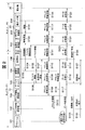
- FIG. 2 is a sequence diagram showing an operation when the information processing apparatus 10 of the network 1 and the multifunction machine 30 connected to the network 2 are virtualized and controlled via the mobile terminal 20 in the device control system shown in FIG. It is.
- the mobile terminal 20 is activated by connecting the cable connected to the communication I / F 301 of the MFP 30 connected via LAN in the remote network 2 to the communication I / F unit 204 of the mobile terminal 20.
- the mobile terminal 20 is activated by executing a predetermined connection operation (such as pressing a button) on the mobile terminal 20 after the cable is connected.
- a predetermined connection operation such as pressing a button
- the communication I / F unit 204 is recognized as being connected as a USB device, and the communication I / F unit 204 notifies the device control unit 203 of the connection of the USB device (step S101).
- the device control unit 203 sends a connection notification to the virtualization control unit 202 (step S102), and the virtualization control unit 202 sends a USB device connection notification to the information processing apparatus 10 via the communication control unit 201 (step S102). S103).
- the virtualization control unit 104 of the information processing apparatus 10 receives a connection notification from the mobile terminal 20, and requests device information from the mobile terminal 20 that is the transmission source of the connection notification (step S104).
- the virtualization control unit 202 of the mobile terminal 20 receives a request for device information from the information processing apparatus 10, and transmits the device information of the communication I / F unit 204 recognized as a USB device to the information processing apparatus 10 (step S105).
- information (USB descriptor information) such as a vendor ID, product ID, and serial number of the communication I / F unit 204 is transmitted as device information.
- the virtualization control unit 104 of the information processing apparatus 10 receives device information from the portable terminal 20 and sends this device information to the device driver 103 (step S106). Upon receiving the device information, the device driver 103 generates (adds) the virtual NIC 106 as a communication interface for connecting to the mobile terminal 20 and performing virtualization control (step S107).
- the address information search unit 109 confirms the presence confirmation and response of the multifunction device 30 to the broadcast address of the network 2 in order to acquire the address information set in the communication I / F 301 of the multifunction device 30. Send a command.
- this command is transmitted from the address information search unit 109 to the device driver 103 (step S108), from the device driver 103 to the virtualization control unit 104 (step S109), and from the virtualization control unit 104. It is transmitted to the virtual NIC 106 via the communication control unit 105 (step S110), and transmitted from the virtual NIC 106 to the portable terminal 20 (step S111).
- this command is received by the virtualization control unit 202 from the information processing apparatus 10 via the communication control unit 201, and is transmitted from the virtualization control unit 202 to the device control unit 203 (step S112).
- the data is transmitted from the unit 203 to the communication I / F unit 204 (step S113).
- the communication I / F unit 204 converts the USB data format command into a data format for transmission / reception via the LAN, and transmits the command to the communication I / F 301 of the multifunction machine 30 (step S114).
- the multifunction machine 30 transmits the address information set in the communication I / F 301 to the mobile terminal 20.
- the address information transmitted here is an IP address set in the communication I / F 301 of the multifunction machine 30, and may include a subnet mask and a default gateway.
- the address information is acquired by the address information search unit 109 along a path opposite to the transmission of the command.
- the address information search unit 109 creates an arbitrary IP address within the same segment as the address information set in the communication I / F 301 of the acquired multifunction device 30, and passes it to the address information setting unit 102 (step S115).
- the information processing apparatus 10 uses the address information setting unit 102 to set the address information (IP address) received from the address information search unit 109 in the virtual NIC 106 (step S116).
- the address information setting unit 102 sets address information in the virtual NIC 106 using a UI (not shown) of the information processing apparatus 10. Instead, the mobile terminal 20 transmits address information to the information processing apparatus 10 using the UI (not shown) of the mobile terminal 20, and the address information setting unit 102 of the information processing apparatus 10 addresses the virtual NIC 106. A mechanism for setting information may be used.
- the virtualization control unit 104 When the address information is set in the virtual NIC 106, the virtualization control unit 104 is instructed to perform virtualization control of the communication I / F unit 204 via the virtual NIC 106. Virtualization control is started by operating a UI screen (not shown) of the information processing apparatus 10. Instead of this, an instruction to start virtualization control may be sent to the information processing apparatus 10 by a predetermined operation of the mobile terminal 20.
- the application 101 transmits data to the device driver 103 (step S117), and the device driver 103 performs the virtualization control unit 104.
- the data is transmitted to (step S118).
- the virtualization control unit 104 transmits data to the virtual NIC 106 via the communication control unit 105 (step S119), and the virtual NIC 106 transmits data to the portable terminal 20 (step S120).
- the virtualization control unit 202 receives data from the information processing apparatus 10 via the communication control unit 201, and the virtualization control unit 202 transmits data to the device control unit 203 (step S121).
- the device control unit 203 transmits data to the communication I / F unit 204 (step S122), the communication I / F unit 204 converts the data in the USB format into a format for transmitting and receiving via the LAN, and the multifunction device 30.
- the data converted into the communication I / F 301 is transmitted (step S123).
- the multifunction device 30 executes operations such as printing and scanning in response to the received data, and transmits status data and scan data to the portable terminal 20. These data are acquired by the application 101 along a path opposite to the transmission of the data.
- the information processing apparatus 10 transmits / receives data to / from the mobile terminal 20 via the virtual NIC 106, and virtualizes the communication I / F unit 204 of the mobile terminal 20. As a result, the information processing apparatus 10 recognizes and controls the same state as when the MFP 30 connected to the communication I / F unit 204 is locally connected.
- a predetermined end operation for example, pressing an end button or an operation using a UI screen
- the virtualization control unit 104 of the information processing apparatus 10 transmits a control end request to the information processing apparatus 10 via the communication control unit 201 (step S124).
- the virtualization control end operation can also be executed from the information processing apparatus 10.
- the information processing apparatus 10 sends a control end request received from the mobile terminal 20 to the device driver 103, and the device driver 103 sends a control end request to the application 101 (step S125).
- the application 101 Upon receiving the control end request, the application 101 instructs the virtualization control unit 104 to end the virtualization control of the communication I / F unit 204 of the mobile terminal 20, and the virtualization control unit 104 displays the communication I / F unit 204. The virtualization control of is terminated.
- the application 101 instructs the device driver 103 to end the virtual NIC 106 (step S126), and the device driver 103 ends the virtual NIC 106 (step S127).
- the communication I / F unit 204 of the mobile terminal 20 is an interface other than a LAN
- necessary setting contents are set on the information processing apparatus 10 side according to the device.
- the setting may be made according to the device, such as setting using a UI on the mobile terminal 20 side or a communication application (both not shown).
- the mobile terminal 20 when data communication is performed between the information processing apparatus 10 of the network 1 and the MFP 30 of the network 2, the mobile terminal 20 is prepared on the network 2 side. Then, the information processing apparatus 10 and the mobile terminal 20 of the network 1 are connected by a communication line, and the MFP 30 is connected to the communication I / F unit of the mobile terminal 20, so that the information processing apparatus 10 communicates with the mobile terminal 20. It becomes possible to operate (virtualization control) the multi-function device 30 via the I / F unit 204.
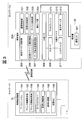
- FIG. 3 is a block diagram showing an example of a schematic configuration of a device control system according to the second embodiment of the present invention.
- the information processing apparatus 10 controls the internal device (input device, display device) of the mobile terminal 20 to be virtualized, so that an operation from the internal device of the mobile terminal 20 is performed. Send to.
- the information processing apparatus 10 is characterized in that the multifunction machine 30 is remotely operated.
- the device control system in FIG. 3 includes an information processing apparatus 10, a portable terminal 20A, and a multifunction device 30, and the configuration of the portable terminal 20A is different from the device control system shown in FIG. Since other connection configurations and components are the same as those in FIG. 1, the same components as those shown in FIG. 1 are denoted by the same reference numerals, description thereof is omitted, and only different points will be described.
- the mobile terminal 20A includes a virtual device control unit 205 and an internal device 213 in addition to the configuration of the mobile terminal 20 of FIG.
- the internal device 213 (input / output device) includes an input device 211 and a display device 212 that are used as a user interface, and is connected to each other via an internal bus 208 by an input I / F 209 and a display I / F 210, respectively.
- the input device 211 is, for example, a software keyboard that implements functions such as a keyboard, a numeric keypad, and a mouse with software.
- the display device 212 is, for example, a liquid crystal monitor.
- the virtual device control unit 205 includes virtual device identification information 206 and a data format conversion processing unit 207.
- the virtual device identification information 206 is information for causing the information processing apparatus 10 to recognize that the input device 211 and the display device 212 of the mobile terminal 20A are USB devices connected to the own apparatus.
- the data format conversion processing unit 207 includes packet data (USB data) that conforms to the USB data format (first data format) transmitted / received to / from the virtualization control unit 202, an input I / F 209, and a display I / F 210.
- the data is converted into data in a data format (second data format) that can be processed by the internal device 213 that transmits / receives the data.
- data is transmitted and received without performing the conversion process.
- the input device 211 and the display device 212 are internal devices of the mobile terminal 20A, and do not have individual identification information (device information) such as a vendor ID, a product ID, and descriptor information unlike a USB device connected by a USB interface. Therefore, information corresponding to these is created in a pseudo manner, assigned to the input device 211 and the display device 212 as virtual device identification information 206, and stored in the virtual device control unit 205 or the like.
- device information such as a vendor ID, a product ID, and descriptor information unlike a USB device connected by a USB interface. Therefore, information corresponding to these is created in a pseudo manner, assigned to the input device 211 and the display device 212 as virtual device identification information 206, and stored in the virtual device control unit 205 or the like.
- the USB descriptor that identifies the HID class is sent to the virtualization control unit 202 as the virtual device identification information 206 related to the input device 211 such as a keyboard and a mouse. Further, the data format conversion processing unit 207 converts the input data input from the input device 211 into USB data of the HID class and sends it to the virtualization control unit 202 via the input I / F 209.
- the USB descriptor identifying the vendor specific information is sent to the virtualization control unit 202 as the virtual device identification information 206 related to the display device 212 such as a display.
- the data format conversion processing unit 207 converts the USB data sent from the virtualization control unit 202 into the data format of the display device 212 and sends it to the display device 212 via the display I / F 210.
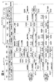
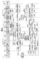
- FIG. 4 is a sequence diagram showing the operation of virtualization control in the device control system shown in FIG.
- the information processing apparatus 10 recognizes the communication I / F unit 204 as a USB device, and the virtual NIC 106 is generated as a communication interface for connecting to the mobile terminal 20A and performing virtualization control. Since the process (steps S201 to S207) is the same as the sequence from step S101 to step S107 in FIG. 2 described in the first embodiment, description thereof is omitted.
- the user operates the mobile terminal 20A to display an operation screen on the display device 212.
- a connection operation using the input device 211 for example, pressing of a connection button
- the internal device 213 requests the virtual device control unit 205 to connect the internal device 213 (step S209).
- the virtual device control unit 205 When detecting the connection request, the virtual device control unit 205 sends a connection request for the internal device 213 including the virtual device identification information 206 of the display device 212 and the input device 211 to the virtualization control unit 202 (step S210).
- the virtualization control unit 202 Upon receiving the connection request including the virtual device identification information 206, the virtualization control unit 202 transmits a connection request to the information processing apparatus 10 via the communication control unit 201 (step S211).
- the information processing apparatus 10 sends the connection request received from the mobile terminal 20A to the virtualization control unit 104 via the virtual NIC 106, and the virtualization control unit 104 sends the connection request to the device driver 103 (step S212).
- the device driver 103 sends a connection request for the internal device 213 of the mobile terminal 20A to the application 101 (step S213).
- the application 101 instructs the virtualization control unit 104 to start virtualization control of the internal device 213 corresponding to the virtual device identification information 206 included in the connection request, and the virtualization control unit 104 The virtualization control of the internal device 213 is started.
- the application 101 transmits screen data to the device driver 103 (step S214, the device driver 103 transmits screen data to the virtualization control unit 104 (step S215). Thereafter, the virtualization control unit 104 transmits screen data to the virtual NIC 106 via the communication control unit 105 (step S216), and the virtual NIC 106 transmits the screen data to the mobile terminal 20A.
- the virtualization control unit 202 receives screen data from the information processing apparatus 10 via the communication control unit 201, and the virtualization control unit 202 transmits screen data to the virtual device control unit 205 (step S217).
- the virtual device control unit 205 transmits screen data to the display device 212 via the display I / F 210 connected to the internal bus 208 (step S218), and the screen is displayed on the display device 212.
- the information processing apparatus 10 starts virtualization control of the internal device 213 of the mobile terminal 20A and sends the input data input from the input device 211 to the information processing apparatus 10, the reverse path to the transmission of the screen data
- the input data received via the input I / F 209 connected to the internal bus 208 is transferred to the application 101 via the virtual device control unit 205, the virtualization control unit 202, the virtualization control unit 104, and the device driver 103. Sent to.
- the data format conversion processing unit 207 of the virtual device control unit 205 converts the USB data sent from the virtualization control unit 202 into the data format (third data format) of the display device 212. Then, the data is transmitted via the display I / F, the data input by the operation of the input device 211 is received via the input I / F, and the input data is converted into USB data (fourth data format). To the virtualization control unit 202.
- screen data (for example, an image displayed on a liquid crystal panel connected to the information processing apparatus 10) sent from the information processing apparatus 10 is displayed on the display device 212 of the mobile terminal 20A. Further, by operating the input device 211, it is possible to perform an input operation similar to that of a keyboard or a numeric keypad on the information processing apparatus 10.
- step S2128 it is possible to operate the information processing apparatus 10 by operating the input device 211 while checking the display device 212 on the portable terminal 20A side.
- the user operates the input device 211 while confirming the display device 212 of the mobile terminal 20A, and inputs the address information (IP address) of the virtual NIC 106 generated by the information processing apparatus 10 (step S219).
- IP address When the address information (IP address) is input from the input device 211, this address information is sent to the virtual device control unit 205 (step S220).
- the virtual device control unit 205 converts the data format and sends it to the virtualization control unit 202 (step S221).
- the virtualization control unit 202 transmits this address information to the information processing apparatus 10 via the communication control unit 201 (step S222).
- the information processing apparatus 10 sends the address information received from the mobile terminal 20A to the virtualization control unit 104, and the virtualization control unit 104 sends the address information to the address information setting unit 102 (step S223).
- the address information setting unit 102 sets address information (IP address) of the same segment as the network 2 to which the multifunction machine 30 is connected to the virtual NIC 106 based on the address information (step S224).
- IP address IP address
- the IP addresses of the multifunction machine 30 and the virtual NIC 106 are set to the same segment, and the information processing apparatus 10 can transmit / receive data to / from the multifunction machine 30 via the portable terminal 20B.
- step S225 to S231 Regarding the data transmission / reception process (steps S225 to S231) between the information processing apparatus 10 and the multifunction machine 30 performed via the portable terminal 20A, from step S117 to step S123 of FIG. 2 described in the first embodiment. Since this is the same as the sequence, the description is omitted.
- the portable terminal 20A is operated to display the operation screen on the display device 212, and an end operation (for example, pressing of the end button) by the input device 211 is executed (step) S232).
- an end operation for example, pressing of the end button
- a control end request for the internal device 213 is sent from the internal device 213 to the virtual device control unit 205 (step S233). Note that the end operation can also be executed from the information processing apparatus 10.
- the virtual device control unit 205 sends a control end request for the internal device 213 to the virtualization control unit 202 (step S234), and the virtualization control unit 202 sends this control end notification to the information processing apparatus 10 via the communication control unit 201. Transmit (step S235).
- the information processing apparatus 10 sends the control end notification received from the mobile terminal 20A to the device driver 103, and the device driver 103 sends this control end request to the application 101 (step S236).
- the application 101 When the application 101 receives the control end request, the application 101 instructs the virtualization control unit 104 to end the virtualization control of the communication I / F unit 204 of the mobile terminal 20 ⁇ / b> A.
- the virtualization control is terminated (step S237).
- the application 101 instructs the device driver 103 to end the virtual NIC 106, and the device driver 103 ends the virtual NIC 106 (step S238).
- the display device 212 switches to the display state before the virtualization control.
- a display device liquid crystal monitor
- a software keyboard is controlled as an input device.
- other internal devices in the mobile terminal are virtualized. It is also possible to control.
- the information processing apparatus 10 performs virtualization control using the NFC card reader built in the mobile terminal 20A as a USB device (internal device). Let As a result, the information processing apparatus 10 and the multifunction device 30 can perform data communication via the NFC communication interface.
- NFC Near Field Communication
- the camera function built in the mobile terminal 20A on the network 2 side is changed to the virtual device identification information 206.
- USB camera To be recognized as a USB device (hereinafter referred to as “USB camera”).
- the internal device 213 of the mobile terminal 20A is virtualized by the information processing apparatus 10 to display the display screen of the information processing apparatus 10 on the display device 212 of the mobile terminal 20A and
- the information processing apparatus 10 can be operated using the input device 211 of the terminal 20A.
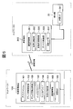
- FIG. 5 is a block diagram showing an example of a schematic configuration of a device control system according to the third embodiment of the present invention.
- the third embodiment of the present invention is characterized in that the amount of network packets transmitted and received between the information processing apparatus 10B and the portable terminal 20B is reduced.
- the device control system in FIG. 5 includes an information processing apparatus 10B, a portable terminal 20B, and a multifunction device 30, and the configurations of the information processing apparatus 10B and the portable terminal 20B are different from the device control system illustrated in FIG. .
- the filter driver 108 stores in advance a transmission pattern of a periodic polling packet that is transmitted in order to check the state of the device. Upon receiving the transfer request from the device driver 103, the filter driver 108 generates pseudo response information (hereinafter referred to as “pseudo response”) for the transfer request. Accordingly, the filter driver 108 sends a pseudo response according to the transmission pattern until a notification indicating a change in the operation state is sent from the communication I / F unit 204 of the mobile terminal 20B recognized as a USB device.
- pseudo response information hereinafter referred to as “pseudo response”
- the mobile terminal 20B includes an automatic communication control unit 220 in addition to the configuration of the mobile terminal 20 of FIG.
- the automatic communication control unit 220 stores a polling transmission pattern corresponding to the transmission pattern of the filter driver 108 in advance.
- the automatic communication control unit 220 performs polling on the communication I / F unit 204 according to this transmission pattern, and repeats polling until a change in the operation state of the communication I / F unit 204 is detected. Then, when detecting a change in the operation state of the communication I / F unit 204, the automatic communication control unit 220 notifies the information processing apparatus 10B via the communication control unit 201 of information indicating this detection (state change notification).
- FIG. 6 is a sequence diagram showing the operation of virtualization control in the device control system shown in FIG. Note that the filter driver 108 of the information processing apparatus 10B and the automatic communication control unit 220 of the portable terminal 20B will be described assuming that a transmission pattern of a periodic polling packet to be transmitted in order to check the device state is stored in advance. .
- the mobile terminal 20B is operated to cause the information processing apparatus 10B to recognize the communication I / F unit 204 as a USB device, and the virtual NIC 106 is generated as a communication interface for virtualizing control by connecting to the mobile terminal 20B.
- the process until the address information is set in the virtual NIC 106 (steps S301 to S316) is the same as the sequence from step S101 to step S116 in FIG. 2 described in the first embodiment, and thus the description thereof is omitted.
- the information processing apparatus 10B causes the filter driver 108 to start polling when a network session for virtualization control is started with the mobile terminal 20B. For example, when the device driver 103 issues a USB interrupt transfer communication request, the filter driver 108 generates a pseudo response to the communication request and returns it to the device driver 103 according to a polling packet transmission pattern stored in advance ( Step S317).
- the device driver 103 When the device driver 103 receives the pseudo response, the device driver 103 recognizes that the response from the communication I / F unit 204 of the mobile terminal 20B has been received by periodic polling, and issues the next communication request. This is repeated until a state change notification (described later) is received from the communication I / F unit 204 of the mobile terminal 20B.
- the automatic communication control unit 220 sends a polling packet (for example, USB interrupt transfer) to the device control unit 203. Communication request) is sent (step S318).
- the device control unit 203 transmits a polling packet to the communication I / F unit 204 (step S319).
- the processes in steps S318 to S319 are repeated until a change in the operation state of the communication I / F unit 204 is detected.
- step S320 When the operation state of the communication I / F unit 204 changes, the change of the operation state is notified to the device control unit 203 (step S320). Next, the device control unit 203 sends this notification (hereinafter referred to as “state change notification”) to the automatic communication control unit 220 (step S321). The automatic communication control unit 220 transmits the received state change notification to the information processing apparatus 10B via the communication control unit 201 (step S322).
- the virtual NIC 106 of the information processing apparatus 10B sends the state change notification received from the mobile terminal 20B to the virtualization control unit 104 (step S323).
- the virtualization control unit 104 sends this state change notification to the filter driver 108 (step S324).
- the filter driver 108 sends this state change notification to the application 101 (step S325).
- the information processing apparatus 10B can transmit and receive data to and from the multifunction machine 30 via the portable terminal 20B.
- step S326 to S332 With respect to the data transmission / reception process (steps S326 to S332) between the information processing apparatus 10B and the multifunction device 30 performed via the portable terminal 20B, the processes from step S117 to step S123 of FIG. 2 described in the first embodiment are performed. Since this is the same as the sequence, the description is omitted.
- step S333 to S337 the process for ending the virtualization control by the information processing apparatus 10B (steps S333 to S337) is the same as the sequence from step S124 to step S127 of FIG. 2 described in the first embodiment, and therefore will be described. Is omitted.
- the polling packet periodically transmitted from the device driver 103 of the information processing apparatus 10B to the mobile terminal 20B and the response of the polling packet are not issued on the network every time. Therefore, the amount of network packets issued between the information processing apparatus 10B and the mobile terminal 20B can be suppressed.
- each of the information processing apparatus, the portable terminal, and the multifunction peripheral is configured as one unit, but the number is not limited to the example illustrated.
- the multifunction machine 30 is not limited to an office device, and may be various embedded devices, mobile phones, or mobile terminal devices.
- the aspect of the present invention is also achieved by a computer of a system or apparatus (or a device such as a CPU or MPU) that reads and executes a program stored in a storage device in order to realize the functions of the above-described embodiments,
- the steps are also achieved by a method executed by a computer of a system or apparatus by reading and executing a program stored in a storage device to realize the functions of the above-described embodiments, for example.
- the program is provided to the computer, for example, via a network or from various recording media that serve as storage devices (eg, computer-readable media).
Abstract
ネットワーク1の情報処理装置が、ネットワーク1とは別のネットワーク2に接続されているデバイスとデータ通信を行う際、携帯端末が具備する通信インターフェースに制御対象とするデバイスを接続し、携帯端末を介して情報処理装置がデバイスを遠隔操作できるようにする。ネットワーク1の情報処理装置とネットワーク2のデバイスとの間でデータ通信を行う際、ネットワーク2側に携帯端末を用意し、情報処理装置と携帯端末を通信回線で接続し、携帯端末通信I/F部に制御対象のデバイスを接続する。情報処理装置には携帯端末の通信I/F部の個体識別情報が送られ、この個体識別情報に基づいて仮想NICが生成され、携帯端末では情報処理装置が仮想NICを介して携帯端末の通信I/Fに接続されたデバイスを直接接続されるようにシミュレートさせる。
Description
本発明は、ネットワークを介してプリンタなどのデバイスを制御するための情報処理装置、携帯端末、デバイス制御システム、およびその制御方法に関する。
従来から、仮想的なプライベートネットワーク(VPN)を構築し、自宅やオフィスのLANに接続したパーソナルコンピュータ等の情報処理装置から遠隔地のネットワークに接続されている機器(PC、周辺機器)を遠隔操作するリモートデスクトップ技術が知られている。VPNは、例えば、インターネット回線やモバイルネットワーク(携帯電話回線)などの通信回線を介して、機密を保持したまま遠隔地のネットワーク同士をLANで接続しているのと同じように接続し、データ通信を可能にする。
また、複数の周辺機器(ディスプレイやマウス、キーボード、プリンタ等)をハブ装置を介して集約してスマートフォン等の携帯端末に接続し、携帯端末とネットワークを介して接続されるリモートサーバによってリモートデスクトップ環境を実現するシステムが提案されている(例えば、特許文献1参照)。
しかしながら、従来技術のリモートデスクトップシステムでは、拠点間を結ぶ通信回線やVPN接続に必要な機器を用意し、機器の設定を行わなければならないため、導入までの手間やコストが掛かかるという課題がある。一方、上述した特許文献1のシステムでは、リモートサーバが携帯端末を介して周辺機器を制御する構成であるため、導入までの手間やコストは低減する。しかし、携帯端末に周辺機器に応じた各種ドライバを導入し、リモートサーバと通信しながら周辺機器を制御するため、携帯端末に負荷が集中してしまうという課題がある。
そこで、本発明は、導入までの手間やコストを低減し、携帯端末に負荷を集中させることなく、携帯端末を介して情報処理装置がデバイスを遠隔操作できるようにした情報処理装置、携帯端末、デバイス制御システム、およびその制御方法を提供することを目的とする。
上記の目的を達成するため、本発明による情報処理装置は、携帯端末とネットワークを介して接続する情報処理装置であって、前記携帯端末の第1のインターフェース手段が有する個体識別情報を取得し、当該個体識別情報に基づいて仮想インターフェースを生成する仮想インターフェース生成手段と、前記生成した仮想インターフェースを介して前記携帯端末の第2のインターフェース手段に接続されたデバイスを直接接続されているようにシミュレートする仮想化制御手段、を備えることを特徴とする。
上記の目的を達成するため、本発明による携帯端末は、第1のデータ形式でデータ送受信する第1のインターフェース手段と、第2のデータ形式でデータ送受信する第2のインターフェース手段とを備えた携帯端末であって、前記第1のインターフェース手段の個体識別情報をネットワークを介して接続された情報処理装置に送信し、当該個体識別情報に基づいて前記情報処理装置が生成する仮想インターフェースを介して前記第2のインターフェース手段に接続されているデバイスを直接接続しているようにシミュレートさせる仮想化制御手段と、前記仮想化制御手段によって前記情報処理装置に前記デバイスをシミュレートさせる際、前記第1のデータ形式と前記第2のデータ形式を相互に変換するデータ形式変換手段を備えることを特徴とする。
本発明によれば、導入までの手間やコストを低減し、携帯端末に負荷を集中させることなく、携帯端末を介して情報処理装置がデバイスを遠隔操作することができる。
以下、本発明の実施形態によるデバイス制御システムの一例について図面を参照して説明する。
[第1の実施形態]
図1は、本発明の第1の実施形態に係るデバイス制御システムの概略構成の一例を示す図である。第1の実施形態に係るデバイス制御システムは、ネットワーク1のLANに接続された情報処理装置10と、ネットワーク1とは別のネットワーク2のLANに接続された携帯端末20及び複合機30とから構成される。
図1は、本発明の第1の実施形態に係るデバイス制御システムの概略構成の一例を示す図である。第1の実施形態に係るデバイス制御システムは、ネットワーク1のLANに接続された情報処理装置10と、ネットワーク1とは別のネットワーク2のLANに接続された携帯端末20及び複合機30とから構成される。
携帯端末20は、複合機30と接続可能な通信インターフェースを備えるとともに、ネットワーク1の情報処理装置10と無線LANやモバイル回線などの無線回線、又は有線回線などの通信回線によって接続される。
なお、ネットワーク2は、ネットワーク1とは別のアドレス体系で管理されている。ネットワーク2は、ネットワーク1と同一フロアのネットワークでもよいし、遠隔地のネットワークであってもよい。
情報処理装置10は、例えば、パーソナルコンピュータ(PC)などであって、図1には示されていないが、ハードウェア構成として、CPU、入力部、表示部、メモリ、記憶部、通信部などを備え、これらハードウェアは内部バスで相互に接続されている。
CPUは情報処理装置10内の各部を制御する中央処理装置である。入力部はキーボードやマウス等の操作装置である。表示部は液晶モニタ等の表示装置である。メモリは、RAM、ROM等の記憶装置である。通信部には、例えば、無線LANやモバイル回線などの無線回線、又は有線回線など通信回線に接続するためのインターフェースであり、通信回線を介してデータ送受信することが可能となる。
記憶部には、図示していないソフトウェアであるオペレーティングシステム(以下「OS」と呼ぶ)と、アプリケーション101、アドレス情報設定部102、アドレス情報探索部109、デバイスドライバ103、仮想化制御部104、通信制御部105、仮想NIC106が記憶されるとともに、他の機能に係るソフトウェアが記憶されている。なお、これらソフトウェアはメモリに読み出されて、CPUの制御に従い動作する。
アプリケーション101は、デバイスドライバ103に対してデータ入出力要求を指示することによって、携帯端末20、複合機30と通信するためのソフトウェアプログラム群である。
アドレス情報設定部102は、仮想NIC106(後述)に対してアドレス情報(IPアドレス)を設定する機能を備えている。なお、アドレス情報としてIPアドレスを例示したが、これに限定されず、MACアドレスや装置名などでもよい。さらに、これらの情報を組み合わせたものであってもよい。
アドレス情報探索部109は、複合機30の通信I/F301に設定されているアドレス情報を探索し、複合機30のアドレス情報を取得する機能を備えている。
デバイスドライバ103は、OS又はアプリケーションからのデータ入出力要求を、複合機30に応じたデータ形式のデータ(以下「制御コマンド」と呼ぶ)に変換して、当該制御コマンドを仮想化制御部104に送る。さらに、デバイスドライバ103は制御コマンドに対する応答をアプリケーション101に通知する。
仮想化制御部104は、デバイスドライバ103から送られた制御コマンド(つまり、データ入出力要求)をUSBデータ形式に準拠したパケットデータ(以下「USBデータ」と呼ぶ)に変換する。また、仮想化制御部104は、通信制御部105から送られてくるUSBデータを制御コマンドと同様のデータ形式に変換してデバイスドライバ103に送る。
さらに、仮想化制御部104は、複合機30に対するデータ送受信要求に対して、複合機30が情報処理装置10に直接的に接続(ローカル接続)されている際と同様の振る舞いをシミュレートする機能(以下「仮想化制御機能」と呼ぶ)を備えている。この仮想化制御機能によって、情報処理装置10は、複合機30がローカル接続されているかのように認識してデータを送受信することができる。
通信制御部105は、仮想化制御部104から送られるUSBデータと携帯端末20と通信する際のネットワークパケットとの変換処理を行って、携帯端末20と情報処理装置10との間のデータ送受信を制御する。また、通信制御部105は、仮想化制御部104から送られるデータ送受信要求に応じて、携帯端末20と情報処理装置10の間の通信回線(のセッション)の接続および切断を制御する。
仮想NIC106は、デバイスドライバ103からの指示に従い、情報処理装置10に仮想化制御により接続されているように認識される携帯端末20の通信I/F部204(後述)のデバイス情報(個体識別情報)に基づいて生成されるネットワークアダプタ(ソフトウェア部品)である。本実施の形態では、通信I/F部204をUSBデバイスとして認識するので、ベンダーID、製品ID、シリアル番号などの情報(USBディスクリプタ情報)に基づいて仮想NIC106が生成される。
携帯端末20は、例えば、携帯電話、PDA、スマートフォンなどの機器であって、ハードウェア構成として、図1には示されていないが、CPU、メモリ、記憶部、通信部などを備えている。
CPUは、携帯端末20内の各部を制御する中央処理装置である。メモリは、RAMおよびROMなどである。通信部は、無線LANやモバイル回線などの無線回線又は有線回線を介してデータ送受信するためのインターフェースであり、これらの回線を介してネットワーク1の情報処理装置10とデータ送受信することが可能となる。
記憶部には、ソフトウェアとして、OS(不図示)、通信制御部201、仮想化制御部202、デバイス制御部203および他の機能に関するソフトウェアが記憶されている。以下、本発明に関わるもののみを説明する。
通信制御部201は、例えば、インターネット回線やモバイルネットワーク(携帯電話回線)など(以下「通信回線」と呼ぶ)と接続して情報処理装置10と携帯端末20の間の通信を制御する。また、通信制御部201は、仮想化制御部202から送られるUSBデータをネットワークパケットへ変換し、通信回線を介して情報処理装置10に送信する。さらに、通信制御部201は、仮想化制御部202を介して上位層のソフトウェア(アプリケーション101、デバイスドライバ103など)から送られるデータ送受信要求に応じて、情報処理装置10と携帯端末20の間のセッションの接続および切断を制御する。
仮想化制御部202は、携帯端末20の通信I/F部204(通信I/F部204を介して接続されたUSBデバイス)が情報処理装置10にローカル接続されているかのように認識させて制御するため、情報処理装置10の仮想化制御部104からの制御要求に従って(連動して)仮想化制御を行う。
デバイス制御部203は、仮想化制御部202の制御に従い、自装置に接続されたデバイスを制御する為のソフトウェアである。本実施の形態では、自装置に接続されたUSBデバイス、即ち、通信I/F部204を制御するためのソフトウェアである。
通信I/F部204は、複合機30のインターフェース(LAN)と携帯端末20のインターフェース(USB)で送受信されるデータ形式を変換する変換装置である。情報処理装置10は、通信I/F部204をUSBデバイス(USB−LAN変換を行うUSBデバイス)として認識する。
なお、通信I/F部204の機能は、複合機30のインターフェースに応じて決定される。複合機30のインターフェースがUSBの場合には、通信I/F部204はUSBインターフェースとなり、複合機30とはUSBケーブルで接続される。また、複合機30のインターフェースがNFC(近距離無線通信)の場合には、通信I/F部204として、USBカードリーダのようなNFCインターフェースを備えたUSBデバイスが携帯端末20に接続される。
例えば、複合機30のインターフェースがWLANであれば、携帯端末20に接続されるUSBデバイスはUSB−WLAN変換アダプタになる。また、複合機30のインターフェースがBluetooth(登録商標)であれば、携帯端末20に接続されるUSBデバイスはUSB−Bluetooth(登録商標)変換アダプタになる。
本実施の形態では、携帯端末20に通信I/F部204が内蔵されているものとして説明する。なお、携帯端末20に通信I/F部204を外付けする形態、例えば、USB−LAN変換アダプタを携帯端末20に接続する形態であってもよい。この場合、携帯端末20にUSB−LAN変換アダプタがケーブルなどで接続されると、OS(不図示)がプラグインを検出し、USBデバイスとして認識する。
複合機30は、プリント機能の他に、スキャン機能、コピー機能、およびストレージ機能などを備えた多機能周辺機器であって、ネットワーク2に接続されているデバイスである。本実施の形態では、通信インターフェースとして通信I/F301を備えており、携帯端末20の通信I/F部204とLANケーブルで接続され、情報処理装置10から携帯端末20を介して制御される。なお、複合機30は別のデバイスであってもよく、通信インターフェースはLANに限定されるものではない。
図2は、図1に示すデバイス制御システムにおいて、ネットワーク1の情報処理装置10とネットワーク2に接続されている複合機30を、携帯端末20を介して仮想化制御する際の動作を示すシーケンス図である。
遠隔地のネットワーク2においてLAN接続されている複合機30の通信I/F301に接続されているケーブルを、携帯端末20の通信I/F部204に接続することにより、携帯端末20を起動する。もしくは、ケーブル接続後に携帯端末20で所定の接続操作(ボタン押下など)を実行することにより、携帯端末20を起動する。これにより、通信I/F部204がUSBデバイスとして接続されたものとして認識され、通信I/F部204からデバイス制御部203に対してUSBデバイスの接続が通知される(ステップS101)。
デバイス制御部203は接続通知を仮想化制御部202に送り(ステップS102)、仮想化制御部202は、通信制御部201を介して情報処理装置10に対してUSBデバイスの接続通知を送る(ステップS103)。
情報処理装置10の仮想化制御部104は、携帯端末20から接続通知を受け取り、この接続通知の送信元である携帯端末20に対してデバイス情報を要求する(ステップS104)。
携帯端末20の仮想化制御部202は、情報処理装置10からデバイス情報の要求を受け取り、USBデバイスとして認識された通信I/F部204のデバイス情報を情報処理装置10に送信する(ステップS105)。本実施の形態では、通信I/F部204のベンダーID、製品ID、シリアル番号などの情報(USBディスクリプタ情報)がデバイス情報として送信される。
情報処理装置10の仮想化制御部104は、携帯端末20からデバイス情報を受け取り、このデバイス情報をデバイスドライバ103に送る(ステップS106)。デバイスドライバ103は、デバイス情報を受け取ると携帯端末20と接続して仮想化制御するための通信インターフェースとして仮想NIC106を生成(追加)する(ステップS107)。
次に、アドレス情報探索部109は、複合機30の通信I/F301に設定されているアドレス情報を取得するため、ネットワーク2のブロードキャストアドレス宛に複合機30の存在確認と応答を確認するためのコマンドを送信する。
本コマンドは、情報処理装置10では、アドレス情報探索部109からデバイスドライバ103に送信され(ステップS108)、デバイスドライバ103から仮想化制御部104に送信され(ステップS109)、仮想化制御部104から通信制御部105を介して仮想NIC106に送信され(ステップS110)、仮想NIC106から携帯端末20に送信される(ステップS111)。
本コマンドは、携帯端末20では、通信制御部201を介して仮想化制御部202が情報処理装置10から受け取られ、仮想化制御部202からデバイス制御部203に送信され(ステップS112)、デバイス制御部203から通信I/F部204に送信される(ステップS113)。その後、通信I/F部204は、USBデータ形式のコマンドをLANで送受信するためのデータ形式に変換し、複合機30の通信I/F301に送信する(ステップS114)。
複合機30は、本コマンドに応答して、通信I/F301に設定されているアドレス情報を携帯端末20に送信する。ここで送信されるアドレス情報は、複合機30の通信I/F301に設定されているIPアドレスであり、サブネットマスク、デフォルトゲートウェイが含まれていても良い。アドレス情報は、上記コマンドの送信とは逆の経路をたどり、アドレス情報探索部109により取得される。
アドレス情報探索部109は、取得した複合機30の通信I/F301に設定されているアドレス情報と同じセグメント内で任意のIPアドレスを作成し、アドレス情報設定部102に渡す(ステップS115)。
次に、情報処理装置10は、アドレス情報設定部102によって、仮想NIC106にアドレス情報探索部109から受け取ったアドレス情報(IPアドレス)を設定する(ステップS116)。
なお、アドレス情報設定部102は、情報処理装置10の(不図示の)UIを使用してアドレス情報を仮想NIC106に設定する。これに代えて、携帯端末20が、携帯端末20の(不図示の)UIを使用してアドレス情報を情報処理装置10に送信し、情報処理装置10のアドレス情報設定部102が仮想NIC106にアドレス情報を設定する仕組みでもよい。
仮想NIC106にアドレス情報が設定されると、仮想化制御部104に当該仮想NIC106を介して通信I/F部204の仮想化制御を指示する。仮想化制御は、情報処理装置10のUI画面(不図示)の操作によって開始する。これに代えて、携帯端末20の所定の操作により、情報処理装置10に仮想化制御開始の指示を送るようにしてもよい。
情報処理装置10が仮想NIC106を介して通信I/F部204の仮想化制御が開始させると、アプリケーション101がデバイスドライバ103にデータを送信し(ステップS117)、デバイスドライバ103が仮想化制御部104にデータを送信する(ステップS118)。その後、仮想化制御部104は通信制御部105を介して仮想NIC106とデータを送信し(ステップS119)、仮想NIC106が携帯端末20にデータを送信する(ステップS120)。
携帯端末20では、通信制御部201を介して仮想化制御部202が情報処理装置10からデータを受信し、仮想化制御部202がデバイス制御部203にデータを送信する(ステップS121)。次に、デバイス制御部203が通信I/F部204にデータを送信し(ステップS122)、通信I/F部204がUSB形式のデータをLANで送受信するための形式に変換し、複合機30の通信I/F301に変換されたデータを送信する(ステップS123)。
複合機30は、受信したデータに応答してプリントやスキャン等の動作を実行し、ステータスデータやスキャンデータを携帯端末20に送信する。これらのデータは、上記データの送信とは逆の経路をたどり、アプリケーション101により取得される。
上述したステップS117~S123により、情報処理装置10は仮想NIC106を経由して携帯端末20とデータを送受信し、携帯端末20の通信I/F部204を仮想化制御する。これにより、情報処理装置10は、通信I/F部204に接続された複合機30をローカル接続した場合と同一の状態であると認識して制御する。
情報処理装置10による仮想化制御を終了させる場合には、携帯端末20で所定の終了操作(例えば、終了ボタンを押下やUI画面による操作)を実行する。これにより、情報処理装置10の仮想化制御部104は通信制御部201を介して制御終了要求を情報処理装置10に送信する(ステップS124)。なお、仮想化制御の終了操作は、情報処理装置10からでも実行することが可能である。
情報処理装置10は、携帯端末20から受信した制御終了要求をデバイスドライバ103に送り、デバイスドライバ103は、アプリケーション101に対して制御終了要求を送る(ステップS125)。
アプリケーション101は、制御終了要求を受けると、仮想化制御部104に携帯端末20の通信I/F部204の仮想化制御の終了を指示し、仮想化制御部104は、通信I/F部204の仮想化制御を終了する。
また、アプリケーション101は、デバイスドライバ103に仮想NIC106の終了を指示し(ステップS126)、デバイスドライバ103は仮想NIC106を終了させる(ステップS127)。
なお、携帯端末20の通信I/F部204がLAN以外のインターフェースの場合は、デバイスに応じて必要な設定内容を情報処理装置10側で設定する。もしくは携帯端末20側のUI、通信アプリケーション(共に不図示)を使って設定するなど、デバイスに応じて設定できるようにしてもよい。
第1の実施形態によれば、ネットワーク1の情報処理装置10と、ネットワーク2の複合機30との間でデータ通信を行う際、ネットワーク2側に携帯端末20を用意する。そして、ネットワーク1の情報処理装置10と携帯端末20とを通信回線で接続し、携帯端末20の通信I/F部に複合機30を接続することにより、情報処理装置10が携帯端末20の通信I/F部204を介して複合機30を操作(仮想化制御)することが可能となる。
[第2の実施形態]
図3は、本発明の第2の実施形態によるデバイス制御システムの概略構成の一例を示すブロック図である。
図3は、本発明の第2の実施形態によるデバイス制御システムの概略構成の一例を示すブロック図である。
本発明の第2の実施形態では、情報処理装置10によって携帯端末20の内部デバイス(入力デバイス、表示デバイス)を仮想化制御させることにより、携帯端末20の内部デバイスからの操作を情報処理装置10に送る。そして、情報処理装置10から複合機30を遠隔操作させる点に特徴がある。
図3のデバイス制御システムは、情報処理装置10、携帯端末20A、複合機30から構成されており、図1で示したデバイス制御システムとは携帯端末20Aの構成が異なっている。その他の接続構成や構成要素は、図1と同じであるため、図1に示す構成要素と同一の構成要素については同一の参照番号を付して説明を省略し、異なる点についてのみ説明する。
携帯端末20Aは、図1の携帯端末20の構成に加えて、仮想デバイス制御部205と内部デバイス213とを備えている。
内部デバイス213(入出力デバイス)は、ユーザインタフェースとして用いられる入力デバイス211および表示デバイス212を備えており、それぞれ入力I/F209およびディスプレイI/F210によって内部バス208で相互に接続されている。
入力デバイス211は、例えば、キーボード、テンキーおよびマウスなどの機能をソフトウェアで実現したソフトウェアキーボードなどである。表示デバイス212は、例えば、液晶モニタである。
仮想デバイス制御部205は、仮想デバイス識別情報206とデータ形式変換処理部207とを有する。
仮想デバイス識別情報206は、情報処理装置10に対して、携帯端末20Aの入力デバイス211および表示デバイス212が自装置に接続されたUSBデバイスであると認識させるための情報である。
データ形式変換処理部207は、仮想化制御部202との間で送受信するUSBデータ形式(第1のデータ形式)に準拠したパケットデータ(USBデータ)と、入力I/F209およびディスプレイI/F210を介して送受信する内部デバイス213で処理可能なデータ形式(第2のデータ形式)のデータとの変換処理を行う。なお、変換が不要なデータ形式の場合は、変換処理を実行せずにデータを送受信する。
入力デバイス211および表示デバイス212は、携帯端末20Aの内部デバイスであり、USBインターフェースで接続するUSBデバイスのようにベンダーID、プロダクトID、ディスクリプタ情報などの個体識別情報(デバイス情報)を持っていない。そのため、これらに相当する情報を擬似的に作成し、仮想デバイス識別情報206として入力デバイス211および表示デバイス212に割り当て、仮想デバイス制御部205などに記憶させておく。
本実施形態において、キーボードおよびマウスなどの入力デバイス211に係る仮想デバイス識別情報206として、HIDクラスを識別したUSBディスクリプタを仮想化制御部202に送る。また、データ形式変換処理部207は、入力デバイス211から入力された入力データをHIDクラスのUSBデータに変換し、入力I/F209を介して仮想化制御部202に送る。
また、ディスプレイなどの表示デバイス212に係る仮想デバイス識別情報206として、ベンダー固有情報(ベンダークラス)を識別したUSBディスクリプタを仮想化制御部202に送る。データ形式変換処理部207は、仮想化制御部202から送られるUSBデータを表示デバイス212のデータ形式に変換して、ディスプレイI/F210を介して表示デバイス212に送る。
図4は、図3に示すデバイス制御システムにおける仮想化制御の動作を示すシーケンス図である。
携帯端末20Aを操作し、情報処理装置10に対して通信I/F部204をUSBデバイスとして認識させ、携帯端末20Aと接続して仮想化制御するための通信インターフェースとして仮想NIC106を生成するまでの過程(ステップS201~S207)は、第1の実施形態で説明した図2のステップS101からステップS107までのシーケンスと同一であるため、説明は省略する。
次に、ユーザは携帯端末20Aを操作して表示デバイス212に操作画面を表示させる。そして、入力デバイス211による接続操作(例えば、接続ボタンの押下)を実行すると(ステップS208)、内部デバイス213から仮想デバイス制御部205に対して内部デバイス213の接続を要求する(ステップS209)。
仮想デバイス制御部205は、この接続要求を検出すると、表示デバイス212および入力デバイス211の仮想デバイス識別情報206を含む内部デバイス213の接続要求を仮想化制御部202に送る(ステップS210)。
仮想化制御部202は、この仮想デバイス識別情報206を含んだ接続要求を受信すると、通信制御部201を介して情報処理装置10に接続要求を送信する(ステップS211)。
情報処理装置10は、携帯端末20Aから受信した接続要求を仮想NIC106を介して仮想化制御部104へ送り、仮想化制御部104は、この接続要求をデバイスドライバ103に送る(ステップS212)。デバイスドライバ103は、アプリケーション101に対して携帯端末20Aの内部デバイス213の接続要求を送る(ステップS213)。
アプリケーション101は、仮想化制御部104に対して、接続要求に含まれる仮想デバイス識別情報206に該当する内部デバイス213の仮想化制御の開始を指示し、仮想化制御部104は、携帯端末20Aの内部デバイス213の仮想化制御を開始する。
情報処理装置10が携帯端末20Aの内部デバイス213の仮想化制御を開始し、表示デバイス212に画面を表示する場合、情報処理装置10では、アプリケーション101がデバイスドライバ103に画面データを送信し(ステップS214)、デバイスドライバ103が仮想化制御部104に画面データを送信する(ステップS215)。その後、仮想化制御部104が通信制御部105を介して仮想NIC106に画面データを送信し(ステップS216)、仮想NIC106は携帯端末20Aに画面データを送信する。
携帯端末20Aでは、通信制御部201を介して仮想化制御部202が情報処理装置10から画面データを受信し、仮想化制御部202が仮想デバイス制御部205に画面データを送信する(ステップS217)。次に、仮想デバイス制御部205が内部バス208に接続されたディスプレイI/F210を介して表示デバイス212に画面データを送信し(ステップS218)、表示デバイス212に画面が表示される。
情報処理装置10が携帯端末20Aの内部デバイス213の仮想化制御を開始し、入力デバイス211から入力された入力データを情報処理装置10に送る場合には、上記画面データの送信とは逆の経路をたどり、内部バス208に接続された入力I/F209を介して受け取られた入力データは、仮想デバイス制御部205、仮想化制御部202、仮想化制御部104、デバイスドライバ103を介してアプリケーション101に送信される。
なお、上述したステップS217、S218において、仮想デバイス制御部205のデータ形式変換処理部207は、仮想化制御部202から送られるUSBデータを表示デバイス212のデータ形式(第3のデータ形式)に変換して、ディスプレイI/Fを介して送信し、入力デバイス211による操作で入力されたデータを入力I/Fを介して受信し、この入力データをUSBデータ(第4のデータ形式)に変換して仮想化制御部202に送信する。
このようにして、携帯端末20Aの表示デバイス212に情報処理装置10から送られてくる画面データ(例えば、情報処理装置10に接続された液晶パネルに表示される画像)が表示される。また、入力デバイス211を操作することによって、情報処理装置10に対してキーボードやテンキーと同様の入力操作を行うことができる。
ステップS218までの動作により、携帯端末20A側の表示デバイス212を確認しながら、入力デバイス211を操作することによって情報処理装置10を操作することが可能になる。
続いて、ユーザは、携帯端末20Aの表示デバイス212を確認しながら、入力デバイス211を操作し、情報処理装置10で生成された仮想NIC106のアドレス情報(IPアドレス)を入力する(ステップS219)。
入力デバイス211からアドレス情報(IPアドレス)を入力すると、このアドレス情報が仮想デバイス制御部205に送られる(ステップS220)。仮想デバイス制御部205は、データ形式を変換し、これを仮想化制御部202に送る(ステップS221)。仮想化制御部202はこのアドレス情報を通信制御部201を介して情報処理装置10に送信する(ステップS222)。
情報処理装置10は、携帯端末20Aから受信したアドレス情報を仮想化制御部104に送り、仮想化制御部104はこのアドレス情報をアドレス情報設定部102に送る(ステップS223)。アドレス情報設定部102は、アドレス情報をもとに仮想NIC106に対して複合機30が接続されているネットワーク2と同じセグメントのアドレス情報(IPアドレス)を設定する(ステップS224)。
このアドレス情報(IPアドレス)設定により、複合機30と仮想NIC106のIPアドレスが同じセグメントに設定され、情報処理装置10は携帯端末20Bを介して複合機30とデータ送受信が可能になる。
なお、第1の実施形態で示したように、アドレス情報探索部109を用いて、仮想NIC106のIPアドレスを設定することも可能である。
携帯端末20Aを介して行われる情報処理装置10と複合機30との間のデータ送受信の過程(ステップS225~S231)については、第1の実施形態で説明した図2のステップS117からステップS123までのシーケンスと同一であるため、説明は省略する。
情報処理装置10による仮想化制御を終了させる場合は、携帯端末20Aを操作して表示デバイス212に操作画面を表示させ、入力デバイス211による終了操作(例えば、終了ボタンの押下)を実行する(ステップS232)。次に、内部デバイス213から仮想デバイス制御部205に対して、内部デバイス213の制御終了要求が送られる(ステップS233)。なお、終了操作は、情報処理装置10からでも実行することが可能である。
仮想デバイス制御部205は内部デバイス213の制御終了要求を仮想化制御部202に送り(ステップS234)、仮想化制御部202は、この制御終了通知を通信制御部201を介して情報処理装置10に送信する(ステップS235)。
情報処理装置10は、携帯端末20Aから受信した制御終了通知をデバイスドライバ103に送り、デバイスドライバ103は、この制御終了要求をアプリケーション101に送る(ステップS236)。
アプリケーション101は、制御終了要求を受けると、仮想化制御部104に携帯端末20Aの通信I/F部204の仮想化制御の終了を指示し、仮想化制御部104は、通信I/F部204の仮想化制御を終了する(ステップS237)。また、アプリケーション101は、デバイスドライバ103に仮想NIC106の終了を指示し、デバイスドライバ103は仮想NIC106を終了させる(ステップS238)。
なお、携帯端末20Aは、内部デバイス213の仮想化制御が終了すると、表示デバイス212が仮想化制御の前の表示状態に切り替わる。
本実施形態の代表的な例として、携帯端末の内部デバイスとして表示デバイス(液晶モニタ)、入力デバイスとしてソフトウェアキーボードの仮想化制御について記載しているが、携帯端末内の他の内部デバイスを仮想化制御することも可能である。
例えば、複合機30がNFC(近距離無線通信)の通信機能を備えている場合、携帯端末20Aに内蔵されているNFCによるカードリーダをUSBデバイス(内部デバイス)として情報処理装置10に仮想化制御させる。これにより、情報処理装置10と複合機30がNFCの通信インターフェースを介して、データ通信を行うことが可能になる。
また、ネットワーク1の情報処理装置10で遠隔地のネットワーク2に属する複合機30のメンテナンス状況を画像で確認したい場合、ネットワーク2側の携帯端末20Aに内蔵されているカメラ機能を仮想デバイス識別情報206を使ってUSBデバイス(以下「USBカメラ」と呼ぶ)として認識させる。USBカメラを情報処理装置10で仮想化制御することにより、ネットワーク2側のUSBカメラで撮影した複合機30の画像をネットワーク1の情報処理装置10で確認することができる。
第2の実施形態によれば、携帯端末20Aの内部デバイス213を情報処理装置10によって仮想化制御させることで、携帯端末20Aの表示デバイス212に情報処理装置10の表示画面を表示させるとともに、携帯端末20Aの入力デバイス211を使って情報処理装置10を操作することが可能となる。
[第3の実施形態]
図5は、本発明の第3の実施形態によるデバイス制御システムの概略構成の一例を示すブロック図である。
図5は、本発明の第3の実施形態によるデバイス制御システムの概略構成の一例を示すブロック図である。
本発明の第3の実施形態では、情報処理装置10Bと携帯端末20Bの間で送受信されるネットワークパケットの量を低減させる点に特徴がある。
図5のデバイス制御システムは、情報処理装置10B、携帯端末20B、複合機30から構成されており、図1で示したデバイス制御システムとは情報処理装置10B及び携帯端末20Bの構成が異なっている。
図5の情報処理装置10Bは、図1の情報処理装置10の構成に加えて、フィルタドライバ108を備えている。
フィルタドライバ108は、デバイスの状態を確認するために送信する定期的なポーリングパケットの送信パターンを予め記憶している。フィルタドライバ108は、デバイスドライバ103から転送要求を受信すると、転送要求に対する擬似的な応答情報(以下「擬似応答」と呼ぶ)を生成する。これにより、フィルタドライバ108は、USBデバイスと認識している携帯端末20Bの通信I/F部204からの動作状態の変化を示す通知が送られてくるまで、送信パターンに従って擬似応答をデバイスドライバ103に返送する。
このようにして情報処理装置10Bからネットワーク(通信回線)を介して携帯端末20に送出されるパケット(転送要求)の一部を抑止し、ネットワーク(通信回線)上のパケット量を低減させている。
携帯端末20Bは、図1の携帯端末20の構成に加えて、自動通信制御部220を備えている。
自動通信制御部220は、フィルタドライバ108の送信パターンに対応するポーリングの送信パターンを予め記憶している。自動通信制御部220は、通信I/F部204に対してこの送信パターンに従ってポーリングを実行し、通信I/F部204の動作状態の変化を検知するまで、ポーリングを繰り返す。そして、自動通信制御部220は、通信I/F部204の動作状態の変化を検知すると、この検知を示す情報(状態変化通知)を通信制御部201を介して情報処理装置10Bに通知する。
このようにして携帯端末20Bからネットワーク(通信回線)介して情報処理装置10Bに送出されるパケットの一部を抑止し、ネットワーク(通信回線)上のパケット量を低減させている。
なお、情報処理装置10B若しくは携帯端末20Bの何れか一方が持っているポーリングパケットの送信パターン情報を相手装置に送信するようにしてもよい。
図6は、図5に示すデバイス制御システムにおける仮想化制御の動作を示すシーケンス図である。なお、情報処理装置10Bのフィルタドライバ108と携帯端末20Bの自動通信制御部220は、デバイスの状態を確認するために送信する定期的なポーリングパケットの送信パターンを予め記憶しているものとして説明する。
まず、携帯端末20Bを操作し、情報処理装置10Bに対して通信I/F部204をUSBデバイスとして認識させ、携帯端末20Bと接続して仮想化制御するための通信インターフェースとして仮想NIC106を生成し、仮想NIC106にアドレス情報を設定するまでの過程(ステップS301~S316)は、第1の実施形態で説明した図2のステップS101からステップS116までのシーケンスと同一であるため、説明は省略する。
情報処理装置10Bは、携帯端末20Bとの間で仮想化制御のためのネットワークセッションが開始されると、フィルタドライバ108によってポーリングを開始させる。例えば、デバイスドライバ103がUSBのインタラプト転送の通信要求を発行すると、フィルタドライバ108は、予め記憶しているポーリングパケットの送信パターンに従い、この通信要求に対する擬似応答を生成してデバイスドライバ103に返す(ステップS317)。
デバイスドライバ103は、擬似応答を受けると、定期的なポーリングにより携帯端末20Bの通信I/F部204からの応答を受信したものとして認識し、次の通信要求を発行する。これを携帯端末20Bの通信I/F部204からの状態変化通知(後述)を受信するまで繰り返す。
一方、携帯端末20Bでは、情報処理装置10Bとの間で仮想化制御のためのネットワークセッションが開始されると、自動通信制御部220が、デバイス制御部203にポーリングパケット(例えば、USBのインタラプト転送の通信要求)を送る(ステップS318)。次に、デバイス制御部203は、通信I/F部204に対するポーリングパケットを送信する(ステップS319)。このステップS318~S319の処理を通信I/F部204の動作状態の変化を検知するまで繰り返す。
通信I/F部204の動作状態が変化すると、この動作状態の変化をデバイス制御部203に通知する(ステップS320)。次に、デバイス制御部203は、この通知(以下「状態変化通知」と呼ぶ)を自動通信制御部220に送る(ステップS321)。自動通信制御部220は、受信した状態変化通知を通信制御部201を介して情報処理装置10Bに送信する(ステップS322)。
情報処理装置10Bの仮想NIC106は、携帯端末20Bから受信した状態変化通知を仮想化制御部104に送る(ステップS323)。次に、仮想化制御部104は、この状態変化通知をフィルタドライバ108に送る(ステップS324)。フィルタドライバ108は、この状態変化通知をアプリケーション101に送る(ステップS325)。
アプリケーション101が状態変化通知をフィルタドライバ108から受信すると、情報処理装置10Bは、携帯端末20Bを介して複合機30とデータ送受信が可能になる。
携帯端末20Bを介して行われる情報処理装置10Bと複合機30との間のデータ送受信の過程(ステップS326~S332)については、第1の実施形態で説明した図2のステップS117~ステップS123までのシーケンスと同一であるため、説明は省略する。
また、情報処理装置10Bによる仮想化制御を終了させるための過程(ステップS333~S337)は、第1の実施形態で説明した図2のステップS124~ステップS127までのシーケンスと同一であるため、説明は省略する。
第3の実施形態によれば、情報処理装置10Bのデバイスドライバ103が携帯端末20Bに対して定期的に送出するポーリングパケット及びこのポーリングパケットの応答を毎回ネットワーク上に発行することがなくなる。そのため、情報処理装置10Bと携帯端末20B間のネットワークパケットの発行量を抑えることができる。
以上、本発明について実施形態に基づいて説明したが、本発明は、これらの実施形態に限定されるものではなく、この発明の要旨を逸脱しない範囲の様々な形態も本発明に含まれる。
上述した第1~第3の実施形態に示すデバイス制御システムは、情報処理装置、携帯端末、複合機がそれぞれ1台で構成されているが、その台数は図示の例に限定されない。また、複合機30はオフィス機器に限定されるものではなく、様々な組込み装置、携帯電話機、又はモバイル端末機器であってもよい。
本発明の態様は、上述した実施の形態の機能を実現するために記憶装置に格納されたプログラムを読み出して実行するシステム又は装置(又はCPU若しくはMPUのようなデバイス)のコンピュータによっても達成され、また、ステップが、例えば上述した実施の形態の機能を実現するために記憶装置に格納されたプログラムを読み出して実行することによってシステム又は装置のコンピュータによって実行される方法によっても達成される。このために、プログラムは、例えば、ネットワークを介して又は記憶装置(例えば、コンピュータ読み取り可能な媒体)として役割を果たす種々の記録媒体からコンピュータに提供される。
本発明は、例示的な実施の形態を参照して記載されているが、開示された例示的実施の形態に限定されると解されるべきではない。以下に記載の請求の範囲は、すべての変形例や同等の構成及び機能を包含するように最も広く解釈されるべきである。
10、10B 情報処理装置
20、20A、20B 携帯端末
30 複合機
20、20A、20B 携帯端末
30 複合機
Claims (16)
- 携帯端末とネットワークを介して接続する情報処理装置であって、
前記携帯端末の第1のインターフェース手段が有する個体識別情報を取得し、当該個体識別情報に基づいて仮想インターフェースを生成する仮想インターフェース生成手段と、
前記生成した仮想インターフェースを介して前記携帯端末の第2のインターフェース手段に接続されたデバイスを直接接続されているようにシミュレートする仮想化制御手段、を備えた情報処理装置。 - 前記仮想インターフェースに対してアドレス情報を設定するアドレス情報設定手段を更に備えていることを特徴とする請求項1に記載の情報処理装置。
- 前記携帯端末の第2のインターフェースの動作状態の変化を検知するまでの間、上位層から前記デバイスに対して送出される要求情報に対する応答情報を擬製して上位層に通知する状態変化検知手段を更に備えたことを特徴とする請求項1又は2に記載の情報処理装置。
- 第1のデータ形式でデータ送受信する第1のインターフェース手段と、第2のデータ形式でデータ送受信する第2のインターフェース手段とを備えた携帯端末であって、
前記第1のインターフェース手段の個体識別情報をネットワークを介して接続された情報処理装置に送信し、当該個体識別情報に基づいて前記情報処理装置が生成する仮想インターフェースを介して前記第2のインターフェース手段に接続されているデバイスを直接接続しているようにシミュレートさせる仮想化制御手段と、
前記仮想化制御手段によって前記情報処理装置に前記デバイスをシミュレートさせる際、前記第1のデータ形式と前記第2のデータ形式を相互に変換するデータ形式変換手段、を備えた携帯端末。 - 前記仮想インターフェースにアドレス情報を設定するアドレス情報設定手段を更に備えていることを特徴とする請求項4に記載の携帯端末。
- 前記携帯端末が具備する所定の機能を自らに接続された内部デバイスとして前記情報処理装置に識別させるための仮想デバイス識別情報を記憶する識別情報記憶手段と、
前記仮想デバイス識別情報を前記情報処理装置に送信する識別情報送信手段と、
前記情報処理装置が前記仮想デバイス識別情報に応じて識別した前記内部デバイスを制御する際、前記内部デバイスとの間のデータ通信は第3のデータ形式に変換し、前記情報処理装置との間のデータ通信は第4のデータ形式に変換して制御する仮想デバイス制御手段とを有することを特徴とする請求項4又は5に記載の携帯端末。 - 前記第2のインターフェースの動作状態の変化を検知するまでの間、前記情報処理装置から送られてくる要求情報を擬製して当該第2のインターフェースに送り、前記擬製した要求情報に対する応答情報を前記情報処理装置に対して送信しないように制御する自動通信制御手段を更に備えたことを特徴とする請求項4乃至請求項6のいずれか1項に記載の携帯端末。
- 請求項1又は2の情報処理装置と、請求項4乃至6のいずれか1項の携帯端末とが通信回線を介して接続されているデバイス制御システム。
- 請求項3の情報処理装置と、請求項7の携帯端末とが通信回線を介して接続されているデバイス制御システム。
- 携帯端末とネットワークを介して接続する情報処理装置の制御方法であって、
前記携帯端末の第1のインターフェース手段が有する個体識別情報を取得し、当該個体識別情報に基づいて仮想インターフェースを生成する仮想インターフェース生成ステップと、
前記生成した仮想インターフェースを介して前記携帯端末の第2のインターフェース手段に接続されたデバイスを直接接続されているようにシミュレートする仮想化制御ステップと、を備えた情報処理装置の制御方法。 - 前記仮想インターフェースに対してアドレス情報を設定するアドレス情報設定ステップを更に備えていることを特徴とする請求項10に記載の情報処理装置の制御方法。
- 前記携帯端末の第2のインターフェースの動作状態の変化を検知するまでの間、上位層から前記デバイスに対して送出される要求情報に対する応答情報を擬製して上位層に通知する状態変化検知ステップを更に備えたことを特徴とする請求項10又は11に記載の情報処理装置の制御方法。
- 第1のデータ形式でデータ送受信する第1のインターフェース手段と、第2のデータ形式でデータ送受信する第2のインターフェース手段とを備えた携帯端末の制御方法であって、
前記第1のインターフェース手段の個体識別情報をネットワークを介して接続された情報処理装置に送信し、当該個体識別情報に基づいて前記情報処理装置が生成する仮想インターフェースを介して前記第2のインターフェース手段に接続されているデバイスを直接接続しているようにシミュレートさせる仮想化制御ステップと、
前記仮想化制御ステップにおいて前記情報処理装置に前記デバイスをシミュレートさせる際、前記第1のデータ形式と前記第2のデータ形式を相互に変換するデータ形式変換ステップを備えた携帯端末の制御方法。 - 前記仮想インターフェースにアドレス情報を設定するアドレス情報設定ステップを更に備えていることを特徴とする請求項13に記載の携帯端末の制御方法。
- 前記携帯端末が具備する所定の機能を自らに接続された内部デバイスとして前記情報処理装置に識別させるための仮想デバイス識別情報を記憶する識別情報記憶ステップと、
前記仮想デバイス識別情報を前記情報処理装置に送信する識別情報送信ステップと、
前記情報処理装置が前記仮想デバイス識別情報に応じて識別した前記内部デバイスを制御する際、前記内部デバイスとの間のデータ通信は第3のデータ形式に変換し、前記情報処理装置との間のデータ通信は第4のデータ形式に変換して制御する仮想デバイス制御ステップと、
を有することを特徴とする請求項13又は14に記載の携帯端末の制御方法。 - 前記第2のインターフェースの動作状態の変化を検知するまでの間、前記情報処理装置から送られてくる要求情報を擬製して当該第2のインターフェースに送り、前記擬製した要求情報に対する応答情報を前記情報処理装置に対して送信しないように制御する自動通信制御ステップを更に備えたことを特徴とする請求項13乃至請求項15のいずれか一項に記載の携帯端末の制御方法。
Priority Applications (1)
| Application Number | Priority Date | Filing Date | Title |
|---|---|---|---|
| US14/752,298 US9395941B2 (en) | 2012-12-28 | 2015-06-26 | Information processing apparatus, portable terminal, and control method therefor |
Applications Claiming Priority (4)
| Application Number | Priority Date | Filing Date | Title |
|---|---|---|---|
| JP2012288309 | 2012-12-28 | ||
| JP2012-288309 | 2012-12-28 | ||
| JP2013247802A JP6212367B2 (ja) | 2012-12-28 | 2013-11-29 | 情報処理装置、携帯端末、デバイス制御システム、およびその制御方法 |
| JP2013-247802 | 2013-11-29 |
Related Child Applications (1)
| Application Number | Title | Priority Date | Filing Date |
|---|---|---|---|
| US14/752,298 Continuation US9395941B2 (en) | 2012-12-28 | 2015-06-26 | Information processing apparatus, portable terminal, and control method therefor |
Publications (1)
| Publication Number | Publication Date |
|---|---|
| WO2014104397A1 true WO2014104397A1 (ja) | 2014-07-03 |
Family
ID=51021451
Family Applications (1)
| Application Number | Title | Priority Date | Filing Date |
|---|---|---|---|
| PCT/JP2013/085325 WO2014104397A1 (ja) | 2012-12-28 | 2013-12-25 | 情報処理装置、携帯端末、デバイス制御システム、およびその制御方法 |
Country Status (3)
| Country | Link |
|---|---|
| US (1) | US9395941B2 (ja) |
| JP (1) | JP6212367B2 (ja) |
| WO (1) | WO2014104397A1 (ja) |
Families Citing this family (2)
| Publication number | Priority date | Publication date | Assignee | Title |
|---|---|---|---|---|
| JP6311688B2 (ja) * | 2015-10-22 | 2018-04-18 | コニカミノルタ株式会社 | 一括設定システム、携帯情報装置、連携設定方法および連携設定プログラム |
| US10459855B2 (en) | 2016-07-01 | 2019-10-29 | Intel Corporation | Load reduced nonvolatile memory interface |
Citations (3)
| Publication number | Priority date | Publication date | Assignee | Title |
|---|---|---|---|---|
| JP2010218347A (ja) * | 2009-03-18 | 2010-09-30 | Nec Corp | シンクライアントサーバシステム及びusbデバイスのドライバの管理方法 |
| JP2011129111A (ja) * | 2009-11-18 | 2011-06-30 | Canon Imaging Systems Inc | クライアント装置、デバイス制御方法、およびデバイス制御システム |
| JP2012138694A (ja) * | 2010-12-24 | 2012-07-19 | Canon Imaging Systems Inc | クライアント装置、デバイス制御方法、およびデバイス制御システム |
Family Cites Families (8)
| Publication number | Priority date | Publication date | Assignee | Title |
|---|---|---|---|---|
| DE69330981T2 (de) | 1992-04-20 | 2002-06-27 | 3Com Corp | Vorrichtung zur Netzmittelerweiterung auf entfernte Netzwerke |
| EP1571562B1 (de) * | 2004-03-03 | 2017-11-01 | Swisscom AG | Verfahren, mit welchem eine Telekommunikationsdienstleistung mittels einer elektronischen Adresse beansprucht werden kann |
| JP2008210115A (ja) * | 2007-02-26 | 2008-09-11 | Nec Corp | リモートコンピュータ上でローカル端末のusbデバイスを操作するシステム、その方法及びそのプログラム |
| JP2009098977A (ja) * | 2007-10-17 | 2009-05-07 | Vision Arts Kk | 周辺機器接続システム |
| JP2010117855A (ja) * | 2008-11-12 | 2010-05-27 | Hitachi Ltd | シンクライアントシステム、シンクライアントシステム構成方法、シンクライアントシステムを構成する周辺機器接続装置および計算機 |
| US8683554B2 (en) * | 2009-03-27 | 2014-03-25 | Wavemarket, Inc. | System and method for managing third party application program access to user information via a native application program interface (API) |
| JP5745424B2 (ja) | 2009-11-04 | 2015-07-08 | キヤノンイメージングシステムズ株式会社 | デバイス制御装置、クライアント装置、デバイス制御方法、およびデバイス制御システム |
| JP6216510B2 (ja) | 2012-12-27 | 2017-10-18 | キヤノンイメージングシステムズ株式会社 | 携帯端末、携帯端末の制御方法、およびデバイス制御システム |
-
2013
- 2013-11-29 JP JP2013247802A patent/JP6212367B2/ja not_active Expired - Fee Related
- 2013-12-25 WO PCT/JP2013/085325 patent/WO2014104397A1/ja active Application Filing
-
2015
- 2015-06-26 US US14/752,298 patent/US9395941B2/en not_active Expired - Fee Related
Patent Citations (3)
| Publication number | Priority date | Publication date | Assignee | Title |
|---|---|---|---|---|
| JP2010218347A (ja) * | 2009-03-18 | 2010-09-30 | Nec Corp | シンクライアントサーバシステム及びusbデバイスのドライバの管理方法 |
| JP2011129111A (ja) * | 2009-11-18 | 2011-06-30 | Canon Imaging Systems Inc | クライアント装置、デバイス制御方法、およびデバイス制御システム |
| JP2012138694A (ja) * | 2010-12-24 | 2012-07-19 | Canon Imaging Systems Inc | クライアント装置、デバイス制御方法、およびデバイス制御システム |
Also Published As
| Publication number | Publication date |
|---|---|
| US9395941B2 (en) | 2016-07-19 |
| US20150293730A1 (en) | 2015-10-15 |
| JP6212367B2 (ja) | 2017-10-11 |
| JP2014142920A (ja) | 2014-08-07 |
Similar Documents
| Publication | Publication Date | Title |
|---|---|---|
| JP6098423B2 (ja) | 端末装置とプリンタ | |
| US10067724B2 (en) | Image forming apparatus with selectable service configuration, image forming system including same, and method for selective image formation | |
| JP6069939B2 (ja) | 無線通信機器、通信設定方法および通信設定プログラム | |
| CN105848191B (zh) | 通信装置及控制方法 | |
| JP2012029164A (ja) | 携帯端末及び装置管理方法 | |
| US9264460B2 (en) | Method, apparatus, and system for executing a job in cooperation with a server | |
| JP2012253514A (ja) | 画像入力システム、サーバ装置、サーバ装置の制御方法、及び制御プログラム | |
| US20120236359A1 (en) | Information processing apparatus, control method for information processing apparatus, and storage medium | |
| CA2865725A1 (en) | Information processing system, information processing method, mobile phone, server, and control method and control program thereof | |
| JP7071575B2 (ja) | 情報処理装置及びその制御方法、並びにプログラム | |
| JP2011238006A (ja) | 画像形成システムおよびサーバー装置 | |
| JP2012252466A (ja) | サーバー装置、情報処理装置、それらの制御方法、及び制御プログラム | |
| JP6341786B2 (ja) | 印刷装置、印刷装置の制御方法、プログラム及び印刷システム | |
| JP5932244B2 (ja) | サーバー装置、情報処理装置、それらの制御方法、及び制御プログラム | |
| JP6212367B2 (ja) | 情報処理装置、携帯端末、デバイス制御システム、およびその制御方法 | |
| JP6216510B2 (ja) | 携帯端末、携帯端末の制御方法、およびデバイス制御システム | |
| US10218816B2 (en) | Information processing system, information processing method, server, and control method and control program of server | |
| JP5887835B2 (ja) | 印刷システム、印刷装置、及びプログラム | |
| JP4900576B2 (ja) | プログラム、記憶媒体および画像処理方法 | |
| JP2014154058A (ja) | 画像処理装置 | |
| WO2021181656A1 (ja) | データ処理装置、データ処理方法、及びプログラム | |
| JP5108571B2 (ja) | 機器、データ転送システム、データ転送方法、プログラムおよび記録媒体 | |
| JP2023165196A (ja) | 情報処理システム、情報処理装置、情報処理方法、及びプログラム | |
| JP2018190046A (ja) | デバイス制御装置、デバイス制御方法、およびプログラム | |
| JP2018164162A (ja) | 情報収集システム、画像形成装置およびプログラム |
Legal Events
| Date | Code | Title | Description |
|---|---|---|---|
| 121 | Ep: the epo has been informed by wipo that ep was designated in this application |
Ref document number: 13869482 Country of ref document: EP Kind code of ref document: A1 |
|
| NENP | Non-entry into the national phase |
Ref country code: DE |
|
| 122 | Ep: pct application non-entry in european phase |
Ref document number: 13869482 Country of ref document: EP Kind code of ref document: A1 |