WO2014104043A1 - 射出成形方法及び射出成形品 - Google Patents
射出成形方法及び射出成形品 Download PDFInfo
- Publication number
- WO2014104043A1 WO2014104043A1 PCT/JP2013/084547 JP2013084547W WO2014104043A1 WO 2014104043 A1 WO2014104043 A1 WO 2014104043A1 JP 2013084547 W JP2013084547 W JP 2013084547W WO 2014104043 A1 WO2014104043 A1 WO 2014104043A1
- Authority
- WO
- WIPO (PCT)
- Prior art keywords
- gap
- molding material
- injection
- filler
- molded product
- Prior art date
Links
Images


Classifications
-
- B—PERFORMING OPERATIONS; TRANSPORTING
- B29—WORKING OF PLASTICS; WORKING OF SUBSTANCES IN A PLASTIC STATE IN GENERAL
- B29C—SHAPING OR JOINING OF PLASTICS; SHAPING OF MATERIAL IN A PLASTIC STATE, NOT OTHERWISE PROVIDED FOR; AFTER-TREATMENT OF THE SHAPED PRODUCTS, e.g. REPAIRING
- B29C45/00—Injection moulding, i.e. forcing the required volume of moulding material through a nozzle into a closed mould; Apparatus therefor
- B29C45/0025—Preventing defects on the moulded article, e.g. weld lines, shrinkage marks
-
- B—PERFORMING OPERATIONS; TRANSPORTING
- B29—WORKING OF PLASTICS; WORKING OF SUBSTANCES IN A PLASTIC STATE IN GENERAL
- B29C—SHAPING OR JOINING OF PLASTICS; SHAPING OF MATERIAL IN A PLASTIC STATE, NOT OTHERWISE PROVIDED FOR; AFTER-TREATMENT OF THE SHAPED PRODUCTS, e.g. REPAIRING
- B29C45/00—Injection moulding, i.e. forcing the required volume of moulding material through a nozzle into a closed mould; Apparatus therefor
- B29C45/0046—Details relating to the filling pattern or flow paths or flow characteristics of moulding material in the mould cavity
-
- B—PERFORMING OPERATIONS; TRANSPORTING
- B29—WORKING OF PLASTICS; WORKING OF SUBSTANCES IN A PLASTIC STATE IN GENERAL
- B29C—SHAPING OR JOINING OF PLASTICS; SHAPING OF MATERIAL IN A PLASTIC STATE, NOT OTHERWISE PROVIDED FOR; AFTER-TREATMENT OF THE SHAPED PRODUCTS, e.g. REPAIRING
- B29C45/00—Injection moulding, i.e. forcing the required volume of moulding material through a nozzle into a closed mould; Apparatus therefor
- B29C45/0005—Injection moulding, i.e. forcing the required volume of moulding material through a nozzle into a closed mould; Apparatus therefor using fibre reinforcements
-
- B—PERFORMING OPERATIONS; TRANSPORTING
- B29—WORKING OF PLASTICS; WORKING OF SUBSTANCES IN A PLASTIC STATE IN GENERAL
- B29C—SHAPING OR JOINING OF PLASTICS; SHAPING OF MATERIAL IN A PLASTIC STATE, NOT OTHERWISE PROVIDED FOR; AFTER-TREATMENT OF THE SHAPED PRODUCTS, e.g. REPAIRING
- B29C45/00—Injection moulding, i.e. forcing the required volume of moulding material through a nozzle into a closed mould; Apparatus therefor
- B29C45/17—Component parts, details or accessories; Auxiliary operations
- B29C45/46—Means for plasticising or homogenising the moulding material or forcing it into the mould
- B29C45/56—Means for plasticising or homogenising the moulding material or forcing it into the mould using mould parts movable during or after injection, e.g. injection-compression moulding
-
- B—PERFORMING OPERATIONS; TRANSPORTING
- B29—WORKING OF PLASTICS; WORKING OF SUBSTANCES IN A PLASTIC STATE IN GENERAL
- B29C—SHAPING OR JOINING OF PLASTICS; SHAPING OF MATERIAL IN A PLASTIC STATE, NOT OTHERWISE PROVIDED FOR; AFTER-TREATMENT OF THE SHAPED PRODUCTS, e.g. REPAIRING
- B29C45/00—Injection moulding, i.e. forcing the required volume of moulding material through a nozzle into a closed mould; Apparatus therefor
- B29C45/0025—Preventing defects on the moulded article, e.g. weld lines, shrinkage marks
- B29C2045/0031—Movable mould wall parts in contact with weld lines, e.g. rotating pins for stirring the weld line
-
- B—PERFORMING OPERATIONS; TRANSPORTING
- B29—WORKING OF PLASTICS; WORKING OF SUBSTANCES IN A PLASTIC STATE IN GENERAL
- B29C—SHAPING OR JOINING OF PLASTICS; SHAPING OF MATERIAL IN A PLASTIC STATE, NOT OTHERWISE PROVIDED FOR; AFTER-TREATMENT OF THE SHAPED PRODUCTS, e.g. REPAIRING
- B29C45/00—Injection moulding, i.e. forcing the required volume of moulding material through a nozzle into a closed mould; Apparatus therefor
- B29C45/0025—Preventing defects on the moulded article, e.g. weld lines, shrinkage marks
- B29C2045/0044—Preventing defects on the moulded article, e.g. weld lines, shrinkage marks expelling moulding material outside the mould cavity at the weld line location
-
- B—PERFORMING OPERATIONS; TRANSPORTING
- B29—WORKING OF PLASTICS; WORKING OF SUBSTANCES IN A PLASTIC STATE IN GENERAL
- B29C—SHAPING OR JOINING OF PLASTICS; SHAPING OF MATERIAL IN A PLASTIC STATE, NOT OTHERWISE PROVIDED FOR; AFTER-TREATMENT OF THE SHAPED PRODUCTS, e.g. REPAIRING
- B29C45/00—Injection moulding, i.e. forcing the required volume of moulding material through a nozzle into a closed mould; Apparatus therefor
- B29C45/17—Component parts, details or accessories; Auxiliary operations
- B29C45/46—Means for plasticising or homogenising the moulding material or forcing it into the mould
- B29C45/56—Means for plasticising or homogenising the moulding material or forcing it into the mould using mould parts movable during or after injection, e.g. injection-compression moulding
- B29C2045/569—Means for plasticising or homogenising the moulding material or forcing it into the mould using mould parts movable during or after injection, e.g. injection-compression moulding using a mould part for decreasing and a mould part for increasing the volume of the mould cavity
-
- B—PERFORMING OPERATIONS; TRANSPORTING
- B29—WORKING OF PLASTICS; WORKING OF SUBSTANCES IN A PLASTIC STATE IN GENERAL
- B29C—SHAPING OR JOINING OF PLASTICS; SHAPING OF MATERIAL IN A PLASTIC STATE, NOT OTHERWISE PROVIDED FOR; AFTER-TREATMENT OF THE SHAPED PRODUCTS, e.g. REPAIRING
- B29C45/00—Injection moulding, i.e. forcing the required volume of moulding material through a nozzle into a closed mould; Apparatus therefor
- B29C45/0013—Injection moulding, i.e. forcing the required volume of moulding material through a nozzle into a closed mould; Apparatus therefor using fillers dispersed in the moulding material, e.g. metal particles
-
- B—PERFORMING OPERATIONS; TRANSPORTING
- B29—WORKING OF PLASTICS; WORKING OF SUBSTANCES IN A PLASTIC STATE IN GENERAL
- B29K—INDEXING SCHEME ASSOCIATED WITH SUBCLASSES B29B, B29C OR B29D, RELATING TO MOULDING MATERIALS OR TO MATERIALS FOR MOULDS, REINFORCEMENTS, FILLERS OR PREFORMED PARTS, e.g. INSERTS
- B29K2105/00—Condition, form or state of moulded material or of the material to be shaped
- B29K2105/06—Condition, form or state of moulded material or of the material to be shaped containing reinforcements, fillers or inserts
- B29K2105/12—Condition, form or state of moulded material or of the material to be shaped containing reinforcements, fillers or inserts of short lengths, e.g. chopped filaments, staple fibres or bristles
- B29K2105/14—Condition, form or state of moulded material or of the material to be shaped containing reinforcements, fillers or inserts of short lengths, e.g. chopped filaments, staple fibres or bristles oriented
-
- B—PERFORMING OPERATIONS; TRANSPORTING
- B29—WORKING OF PLASTICS; WORKING OF SUBSTANCES IN A PLASTIC STATE IN GENERAL
- B29K—INDEXING SCHEME ASSOCIATED WITH SUBCLASSES B29B, B29C OR B29D, RELATING TO MOULDING MATERIALS OR TO MATERIALS FOR MOULDS, REINFORCEMENTS, FILLERS OR PREFORMED PARTS, e.g. INSERTS
- B29K2105/00—Condition, form or state of moulded material or of the material to be shaped
- B29K2105/06—Condition, form or state of moulded material or of the material to be shaped containing reinforcements, fillers or inserts
- B29K2105/16—Fillers
- B29K2105/18—Fillers oriented
Definitions
- the present invention relates to an injection molding method and an injection molded product using the same.
- the present invention relates to an injection molding method in which the orientation of the filler is controlled and an injection molded product using the same.
- An injection molding technique in which a melt molding material is introduced into a mold and solidified is one of the technologies that Japan is proud of in the world.
- metallic injection molded products made by mixing filler-like materials such as aluminum, mica and glass flakes with molding materials such as resin are relatively inexpensive without using processes such as plating and painting. It is used as a method for obtaining a high quality texture.
- strength improvement of an injection molded product has been generally used for a long time.
- the injection molded product to which the filler is added has a line scar called a weld line on the surface, which is a cause of defects that deteriorate strength and impair the appearance.
- the filler moves along the joining surface, that is, relative to the flow direction of the injection molded product. It is caused by the orientation to be orthogonal.
- the surface direction can be oriented in parallel with the inflow direction, so that a metallic-like aesthetic can be exhibited. Disturbance of flow when molding materials merge in the cavity of the mold disturbs the orientation of the filler, resulting in flow lines (lines that do not reflect light, dark lines, flow marks, and color irregularities) that impair the appearance.
- Patent Document 1 when melt molding materials including metal particles press-fitted from a plurality of gates included in a cavity portion of a mold merge with each other, two gates into which melt molding materials that merge with each other are press-fitted are disclosed.
- the flow pressure of the melt molding material on one side is stopped at each time difference so that the flow pressure of the melt molding material becomes smaller than the other, and after the melt molding material has joined, the flow pressure from the larger one to the smaller one.
- a flow weir that restricts the flow of resin is disposed so as to be freely retractable from the cavity, and the flow weir protrudes into the cavity so that the resin flows into a predetermined restricted region in the cavity.
- the molten resin is injected into the cavity, and after the start of injection, the resin is removed from the cavity and moved to a position where the flow of the resin is not restricted. And preventing the occurrence of orientation lines that are resin flow patterns.
- thermoplastic resin flows in opposite directions in a cavity at the corner outer peripheral edge of a mold having a corner, and one of the flows corresponds to the corner of the cavity corresponding to the corner.
- the temperature of the mold is maintained at a temperature equal to or higher than the thermal deformation temperature of the thermoplastic resin so that the thermoplastic resin can easily flow, the mold is opened, the thermoplastic resin is injected, and the mold is clamped. It is described that by applying compression in the thickness direction by operation, the thermoplastic resin is flowed to change so that the disorder of the orientation of the glittering material generated at the time of injection is uniform, thereby suppressing the weld line and the flow line.
- the present invention solves the above-described problems, and provides an injection molding method in which the orientation of the filler is controlled and an injection molded product using the same.
- the first gap in the injection molding method using a mold including a first gap and a retracting mechanism disposed in a second gap connected to the first gap, the first gap
- the pull-in mechanism is arranged so that no space is generated between the gap and the pull-in mechanism, the first gap of the mold is filled with a molding material containing a filler, and the first gap of the first gap
- the molding material that has flowed in from a direction and the molding material that has flowed in from a second direction different from the first direction are in close contact with each other, a part of the molding material is pulled by pulling in the drawing mechanism.
- An injection molding method is provided that draws into the two gaps.
- the filler may have an anisotropic shape.
- drawing a part of the molding material into the second gap by pulling the pull-in mechanism may be performed by applying a negative pressure to the second gap.
- a part of the molding material filled in the first gap may be drawn into the second gap to form a rib or a boss.
- pulling a part of the molding material into the second gap by pulling in the drawing mechanism causes the filler and the molding material near the surface layer to move toward the second gap. It may be retracted.
- the injection molded product formed by the method as described in any one of the above is provided.
- the injection molding method which controlled the surface orientation of the filler, and an injection molded product using the same can be provided.
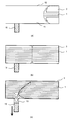
- FIG. 1 It is a schematic diagram explaining the injection molding method which concerns on one Embodiment of this invention, (a) is a schematic diagram which shows the metal mold
- FIG. 9 is a schematic view showing a state in which a weld line is generated by a conventional injection molding method.
- a fountain flow for supplying the filler 1 and the molding material 3 toward the tip of the fluid is generated. This is because the filler 1 and the molding material 3 are supplied from the fluidized bed 5 near the center of the fluid toward the tip, and the skin layer is formed by slightly solidifying the surface layer 7 in contact with the cavity 10. Because.
- the major axis of the filler 1 is oriented in the fluid flow direction (FIG. 9A). .
- the filler 1 and the molding material 3 flowing through the cavity 10 merge from different directions (or at least two directions) and fill the cavity 10 (FIG. 9B). Due to the fountain flow, the filler 1 that has been oriented from the front end portion of the fluid toward the surface layer 7 is oriented along the merged surface when merged from two directions. Since the filler 1 oriented along the merging surface is orthogonal to the filler 1 oriented along the fluid flow direction in the surface layer 7, it becomes a weld line 9 and impairs the appearance (FIG. 9). (C)).
- the molding material flowing in from one side is pushed into the molding material flowing in from the other side or is pushed into a space (also referred to as a discarded cavity) connected in the cavity 10 to prevent the weld line. It was a thing. However, in such a method, since the filler 1 and the molding material 3 are solidifying in the surface layer 7, only the fluidized bed 5 can be moved, resulting in a weld line 9 and a flow line. In addition, even if the mold is heated at this time to improve the fluidity of the surface layer 7, it is difficult to control the vicinity of the surface layer 7 with the above-described prior art. The appearance defect that the surface of the product was dented occurred.
- the inventor In order to suppress such a weld line as well as a flow line, the inventor has paid attention to the fact that it is necessary to move the filler 1 and the molding material 3 up to the vicinity of the surface layer 7.
- the present inventor is not a conventional method of pushing the molding material flowing in from one side into the molding material flowing in from the other, but by moving the molding material flowing in from one side by drawing it to the other molding material side, it cannot be visually recognized by the naked eye
- the inventors have found that it is possible to suppress the occurrence of weld lines and flow lines, that is, it is possible to control the orientation in the vicinity of the skin layer of the injection-molded product, and the present invention has been completed.
- Such a method of moving the molding material flowing from one side by drawing it into the other molding material side is a novel method, which is the opposite principle to the method of pushing in which has been reported.
- the filler has an anisotropic shape, and is a fibrous material or a scaly material in which one is longer than the other.
- the filler effective in the present invention include talc (mica, mica, etc.), glass fiber, carbon fiber, carbon nanotube and the like.
- the present invention is not a technique that can be applied only to an injection-molded product having a metallic color tone, but can be applied to all injection-molded products that contain filler and orient the filler to obtain desired characteristics.
- glass fibers, carbon fibers, carbon nanotubes, and the like can be imparted with desired strength to an injection-molded product by containing them.
- these fillers cannot exhibit functions such as strength improvement and conductivity due to the orientation of the weld line portion.
- the present invention is a technique capable of improving the orientation in the weld line and expressing a desired function.
- the molding material which concerns on this invention is a material which can be injection-molded, it will not specifically limit, A well-known material can be used.
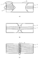
- FIG. 1 is a schematic view for explaining an injection molding method according to the present invention.
- a molding material 3 including a filler 1 is filled in a cavity (first gap) of the mold.
- the mold is provided with a retracting mechanism 15 connected to the first gap.
- the pull-in mechanism 15 is a mechanism that forms a second gap connected to the first gap by a drive mechanism disposed outside the mold and a control mechanism (not shown) that controls the drive mechanism.
- the drawing-in mechanism 15 is arranged close to the first gap to such an extent that the second gap is not generated or slightly generated.
- FIG. 1 (a) the molding material 3 containing the filler 1 is filled in the first gap 11 of the mold, and the molding material 3 flowing in from one side (first direction) of the first gap 11 and the other (first side)
- a second gap 13 connected to the first gap 11 is formed, and the first gap A part of the molding material 3 filled in 11 is drawn and moved in either the first direction or the second direction (FIG. 1C), and the second gap 13 causes the drawing mechanism 15 to move. It can be formed by being driven by a drive mechanism.
- the fluidized bed 5 can only be moved by the conventional pushing method.
- the drawing mechanism 15 is driven to make negative pressure on one side, thereby molding from the other side. Material 3 is drawn into one side.
- the filler 1 in the surface layer 7, the filler 1 is oriented along the fluid flow direction, and not only the fluidized layer 5 but also the filler 1 and the molding material 3 in the vicinity of the surface layer 7 are drawn to one side. As a result, the generation of the weld line 9 and the flow line can be suppressed.
- a part of the molding material 3 filled in the first gap 11 is drawn and moved in either the first direction or the second direction. This can be done by reducing the pressure in either the direction or the second direction. That is, by reducing one of the pressures, a negative pressure is generated on the reduced pressure side, and not only the fluidized bed 5 but also the filler 1 and the molding material 3 in the vicinity of the surface layer 7 can be drawn to one side.
- pulling a part of the molding material 3 filled in the first gap 11 and moving it in either the first direction or the second direction means that the first direction of the first gap 11 is the first direction.
- This is preferably performed when the molding material 3 that has flowed in from and the molding material 3 that has flowed in from a second direction different from the first direction are in close contact with each other.
- the molding material 3 flowing in from two directions comes into close contact, the molding material 3 is moved by drawing it to one side, so that not only the fluidized bed 5 but also the filler 1 and the molding material 3 near the surface layer 7 are drawn to one side. The generation of the weld line 9 and the flow line can be suppressed.
- pulling a part of the molding material 3 filled in the first gap 11 and moving it in either the first direction or the second direction can be achieved by forming the second gap 13.
- This can be done by setting the second gap 13 to a negative pressure and drawing a part of the molding material 3 into the second gap 13.
- a negative pressure is generated on the side where the second gap 13 is generated, and the molding is performed not only on the fluidized bed 5 but also on the filler 1 near the surface layer 7.
- the material 3 can be drawn to one side, and the generation of the weld line 9 and the flow line can be suppressed.
- this invention is not limited only to pulling in the molding material 3 to one side, and suppressing generation
- gap 13 By pulling in, the negative pressure is generated on the side where the second gap 13 is generated, and not only the fluidized bed 5 but also the filler 1 and the molding material 3 in the vicinity of the surface layer 7 are drawn to one side, other than the design surface of the injection molded product This also includes moving the weld line 9 and the flow line.
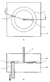
- FIG. 2 is a schematic diagram for explaining an injection molding method according to an embodiment of the present invention.
- 2A is a schematic view showing the mold 19 and the retracting mechanism 15, and
- FIG. 2B is a cross-sectional view taken along AA ′ in FIG. 2A.
- the mold 19 is generally composed of two upper and lower molds 19 (a) and 19 (b).
- the injection-molded product is taken out from the mold 19 by separating the mold 19 (a) and the mold 19 (b).
- the mold 19 is provided with an injection hole 17 for pouring the molding material 3 including the filler 1 and is connected to the first gap 11.
- the mold 19 is provided with a pull-in mechanism 15 connected to the first gap 11, and is arranged close to the first gap 11 to such an extent that the second gap 13 is not generated or slightly generated.
- the molding material 3 including the filler 1 is drawn into one side.
- the position where the drawing-in mechanism 15 is arranged is not particularly limited. Therefore, the drawing-in mechanism 15 may be arranged so as to be shifted to any one side with respect to the joining position of the molding material 3, or may be arranged directly below the joining position.
- the drawing mechanism 15 in the mold 19 has the second gap 13 not generated or slightly generated.
- An arrangement close to one air gap 11 is taken.
- the pulling mechanism 15 is pulled downward by a driving mechanism disposed outside to generate the second gap 13, and the filler
- the molding material 3 including 1 is drawn into the second gap 13.
- the pull-in mechanism 15 is filled with the molding material 3 including the filler 1 in the first gap 11, and when the interior exceeds a predetermined pressure, the pull-in mechanism 15 is lowered downward to generate the second gap 13.
- Such a mechanism may be used.
- the distance by which the drawing mechanism 15 is pulled downward that is, the amount by which the molding material 3 including the filler 1 is drawn to the one side may be an amount that can suppress the generation of the weld line 9 and the flow line. It can be obtained experimentally using the mold 19. Further, when the molding material 3 merged from different directions in the first gap 11 is brought into close contact, in order to draw the molding material 3 including the filler 1 to one side, the pulling mechanism 15 is instantaneously driven, It is preferable to increase the negative pressure, and the time for driving such a retracting mechanism 15 can be obtained experimentally using the mold 19. Here, when the molding material 3 merged from different directions in the first gap 11 comes into close contact, it is obtained in reverse calculation from the driving time of the drawing mechanism 15 that can suppress the generation of the weld line 9 using the mold 19. be able to.
- the arrangement of the pull-in mechanism with respect to the first gap 11 is limited to the lower side of the first gap 11 as shown in Embodiment 1, that is, the back surface of the design surface of the injection molded product. It may be arranged on the side surface of the injection-molded product as shown in FIG.
- the drawing mechanism 25 by arranging the drawing mechanism 25 so as to be driven in the side surface direction of the injection molded product, a part of the molding material 3 is drawn into the second gap 13, thereby generating the second gap 13. It is possible to suppress the generation of the weld line 9 and the flow line by moving the filler 1 and the molding material 3 not only in the fluidized bed 5 but also in the vicinity of the surface layer 7 to the one side. .
- the drawing mechanism 25 is moved in the horizontal direction when the inside of the first gap 11 is filled with the molding material 3 including the filler 1 and exceeds the predetermined pressure, and the second gap 13 It may be a mechanism that generates
- the molding material 3 in order to suppress the generation of the weld line 9 and the flow line, the molding material 3 is moved by being drawn into the second gap 13. For this reason, the drawing mechanism is disposed at a position where the rib or boss of the injection molded product is formed, and a part of the molding material 3 is drawn into the second gap 13 so that the rib and boss are simultaneously molded. You can also
- FIG. 5 is a schematic diagram illustrating an injection molding method according to an embodiment of the present invention. As shown in FIG. 5A, in this embodiment, when the molding material 3 merged from different directions in the first gap 11 is brought into close contact, the molding material 3 including the filler 1 is drawn into one side. The retracting mechanism 35 is arranged so as to be shifted to either one side with respect to the joining position.
- the retracting mechanism 35 is disposed at a position where a rib or a boss is formed. Further, the retracting mechanism 35 is arranged in a shape capable of forming a rib or a boss. Examples include, but are not limited to, hollow cylindrical shapes.
- the pull-in mechanism 35 in the mold 19 is such that the second gap 13 is not generated or slightly generated.
- An arrangement close to one air gap 11 is taken.
- the pulling mechanism 35 is pulled downward by a driving mechanism disposed outside, thereby generating the second gap 13 and the filler.
- the molding material 3 including 1 is drawn into the second gap 13.
- a negative pressure is generated and not only the fluidized bed 5 but also the filler 1 and the molding material 3 in the vicinity of the surface layer 7 can be moved by being drawn to one side.
- ribs and bosses can be formed simultaneously.
- the pulling mechanism 35 is filled with the molding material 3 including the filler 1 in the first gap 11, and when the inside exceeds a predetermined pressure, the pulling mechanism 35 is lowered downward to generate the second gap 13.
- Such a mechanism may be used.
- desired strength and conductivity can be imparted to an injection-molded article by using the above-described injection molding method according to the present invention.
- the above-described talc mica, mica, etc.
- glass fiber, carbon fiber, carbon nanotube, etc. can be used as a filler.
- glass fibers, carbon fibers, carbon nanotubes, and the like can be imparted with high strength to an injection-molded product by being included in the molding material due to the orientation of the weld line portion.
- Carbon fibers, carbon nanotubes, and the like can be imparted with conductivity by the orientation of the weld line portion.
- the molding material used in this embodiment includes polypropylene (PP), ABS resin, polycarbonate (PC), polymethyl methacrylate resin (PMMA), nylon (PA), polyoxymethylene (POM), polyphenylene sulfide resin (PPS).
- PP polypropylene
- PC polycarbonate
- PMMA polymethyl methacrylate resin
- PA nylon
- POM polyoxymethylene
- PES polyphenylene sulfide resin
- Any thermoplastic resin such as polyetheretherketone (PEEK) can be used, but is not limited thereto.
- the content of the filler contained in the molding material is not particularly limited, and can be arbitrarily set according to the strength and conductivity required for the injection molded product.
- the injection-molded product according to the present embodiment suppresses the generation of weld lines and flow lines by moving the filler and molding material in the vicinity of the surface layer to one side by moving them to one side, not only in the fluidized bed, By the orientation of the weld line portion, it is possible to realize an unprecedented strength improvement and conductivity.
- an injection molded product was formed using the injection molding method according to the present invention. Further, as Comparative Examples 1 and 2, an injection molded product was formed by a conventional manufacturing method. In Examples 1 and 2 and Comparative Examples 1 and 2, molding materials obtained by adding a filler of aluminum (Al) to polypropylene (PP) melted at 220 ° C. were used. As Examples 1 and 2, injection molding was performed using the above-described injection molding method according to the present invention with the mold heated to 80 ° C. As Comparative Examples 1 and 2, injection molding was performed without operating the pull-in mechanism 35 in the state where the same mold as in the example was heated to 80 ° C.
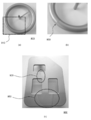
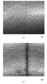
- FIG. 6 is a view showing Comparative Examples 1 and 2 formed by a conventional injection molding method.
- 6A shows an injection molded product 800 of Comparative Example 1
- FIG. 6B is an enlarged view of a portion 810 of FIG. 6A
- FIG. 6C is an injection of Comparative Example 2.
- a molded product 900 is shown.
- a weld line 809 was confirmed in the injection molded product 800 of Comparative Example 1 formed by the conventional injection molding method.
- the weld line 909 and the flow line 950 were confirmed in the injection molded product 900 of the comparative example 2 shown in FIG.6 (c).
- FIG. 8 is an optical microscope image obtained by observing the weld line of the injection molded products of Example 1 and Comparative Example 1.
- FIG. 8A shows an injection-molded article 100 of Example 1
- FIG. 8B shows an injection-molded article 800 of Comparative Example 1.
- the use of the injection molding method according to the present invention can remarkably suppress the occurrence of weld lines.
- ABS resin (melting temperature 230 ° C.), nylon 6 (PA 6) (melting temperature 235 ° C.), and an alloy material of polycarbonate and ABS resin (melting temperature 250 ° C.) are also used. Similar results were obtained.
- Example 3 a JIS K-7139 multipurpose test piece (ISO dumbbell type A1) was molded by the injection molding method according to the present invention, and a molded product 300 was obtained.
- a molded product 1000 was molded by the conventional two-point gate molding, and as a reference example, a molded product 1100 in which the pulling mechanism of the third embodiment was previously pulled to form a resin reservoir was molded.
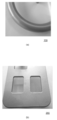
- FIG. 10 is a view showing an injection molded product according to an embodiment of the present invention.
- the appearance of flattening of the raised shape due to the orientation of talc generated in the weld indicated by the arrow was evaluated.
- the appearance was evaluated by visual observation and tactile sensation.
- the bulge due to the weld line was not detected in the visual evaluation and the tactile evaluation.
- the orientation of talc in the weld line that allows visible light to pass through was not detected.
- Example 4 molded by the injection molding method according to the present invention exhibited a tensile strength 4.2 times that of Comparative Example 4 molded by the prior art. From this result, it was clarified that by using the injection molding method according to the present invention, a remarkable improvement in strength can be realized as compared with the conventional case by significantly suppressing the occurrence of weld lines. .
Landscapes
- Engineering & Computer Science (AREA)
- Manufacturing & Machinery (AREA)
- Mechanical Engineering (AREA)
- Chemical & Material Sciences (AREA)
- Dispersion Chemistry (AREA)
- Injection Moulding Of Plastics Or The Like (AREA)
- Moulds For Moulding Plastics Or The Like (AREA)
Abstract
フィラー(1)の表面配向を制御した射出成形方法及びそれを用いた射出成形品を提供する。第1の空隙(11)と、前記第1の空隙に接続する第2の空隙(13)に配置された引き込み機構(15)とを備える金型(19)を用いた射出成形方法において、前記第1の空隙と前記引き込み機構との間に空間が生じないように前記引き込み機構を配置し、前記金型の前記第1の空隙にフィラーを含む成形材料(3)を充填し、前記第1の空隙の第1の方向から流入した前記成形材料と、前記第1の方向とは異なる第2の方向から流入した前記成形材料とが密着したときに、前記引き込み機構を引き込むことにより前記成形材料の一部を前記第2の空隙に引き込こむ。
Description
本発明は射出成形方法及びそれを用いた射出成形品に関する。特にフィラーの配向を制御した射出成形方法及びそれを用いた射出成形品に関する。
溶融成形材料を金型に導入して固化させる射出成形の技術は、我が国が世界に誇る技術の1つである。射出成形において、アルミニウム、マイカ、ガラスフレーク等のフィラー状の材料を樹脂等の成形材料に混合して成形したメタリック調の射出成形品は、メッキ処理や塗装等の工程を用いずに比較的安価に高級な質感を得られる方法として用いられている。また、射出成形品の強度向上のためにフィラーを添加する技術は古くから一般的に用いられている。しかし、フィラーを添加した射出成形品は、表面にウェルドラインと呼ばれる線条痕が生じ、強度低下や美観を損なう不具合の要因となっていた。
このような不具合は、ウェルドラインでは、フィラーを含む成形材料が金型のキャビティに異なる方向から流入して合流したときに、フィラーが合流面に沿って、すなわち、射出成形品の流動方向に対し直行するように配向することにより生じる。また、フィラーが高輝度色調を発生させるためのアルミなど(鱗片状・薄板状)の場合、その面方向が流入する方向と平行に配向することにより、メタリック調の美観を呈することができるが、金型のキャビティ内で成形材料が合流したときの流れの乱れにより、フィラーの配向が乱れ、フローライン(光りの反射が無い線・黒ずんだ線や流動痕・色ムラ)が生じて美観を損なうこともある。
このようなフィラーの配向の乱れによって生じるウェルドラインを防止する工夫が種々報告されている。例えば、特許文献1には、金型のキャビティ部が有する複数のゲートから圧入された金属粒子を含む溶融成形材料が互いに合流する際に、互いに合流する溶融成形材料が圧入される2つのゲートの一方における溶融成形材料の流動圧力が、他方より小さくなるように、複数のゲートからの溶融成形材料の圧入をそれぞれ時間差で停止させ、溶融成形材料が合流したのち、流動圧力が大きい方から小さい方に向けて流動させることにより、溶融成形材料の流動先端部の合流部分における金属粒子を、溶融成形材料の表面で流動方向に沿って整列させる方法が記載されている。
また、特許文献2には、樹脂の流動を制限する流動堰をキャビティに対して出退自在に配設させ、流動堰をキャビティ内に突出させてキャビティにおける所定の制限領域への樹脂の流入を制限した状態で、溶融させた樹脂を前記キャビティ内に射出し、射出開始後に、キャビティから退出して流動堰を樹脂の流動を制限しない位置に移動させることにより、制限領域以外の箇所でのウェルドや樹脂の流動模様である配向ラインの発生を防止することが記載されている。
特許文献3には、コーナー部を有する金型のコーナー部外周縁部に、射出成形時に熱可塑性樹脂がキャビティ内で互いに逆向きに流れ、その一方の流れがコーナー部に対応するキャビティのコーナー部を越えてコーナー部に接近した位置で他方の流れと合流する合流部から他方の流れ方向下流側の延長線上に位置するように突出部が狭小部を介して一体に突設されることにより、合流部では熱可塑性樹脂の流れに乱れが生じ、熱可塑性樹脂に含有されている光沢材にも配向の乱れが生じるが、合流によって一旦乱れた熱可塑性樹脂の流れが樹脂溜まり部に導入されて他方の流れと同じ方向に修正され、光沢材の配向も修正されて熱可塑性樹脂の流れに沿って一方向に並ぶことが記載されている。
また、特許文献4には、金型の温度を熱可塑性樹脂の熱変形温度以上に保ち、熱可塑性樹脂を流動しやすい状態とし、金型を型開き状態で熱可塑性樹脂を射出後、型締め動作によって厚み方向に圧縮をかけることにより、熱可塑性樹脂を流動させて射出時に発生した光輝材の配向の乱れが揃うように変化させ、ウェルドラインやフローラインを抑制することが記載されている。
しかし、何れの方法もフィラー添加材料を用いた射出成形品に生じるウェルドライン部の強度低下や外観不良、及びフローライン(光りの反射が無い線・黒ずんだ線や流動痕・色ムラ)を十分に抑制するものではなく、特にメタリック色調材料の場合、メッキや塗装を施すことなく製品とするには、樹脂材料の種類が限定されるなどの課題があり、更なる改良が必要であった。
本発明は、上述の問題を解決するものであって、フィラーの配向を制御した射出成形方法及びそれを用いた射出成形品を提供する。
本発明の一実施形態によると、第1の空隙と、前記第1の空隙に接続する第2の空隙に配置された引き込み機構とを備える金型を用いた射出成形方法において、前記第1の空隙と前記引き込み機構との間に空間が生じないように前記引き込み機構を配置し、前記金型の前記第1の空隙にフィラーを含む成形材料を充填し、前記第1の空隙の第1の方向から流入した前記成形材料と、前記第1の方向とは異なる第2の方向から流入した前記成形材料とが密着したときに、前記引き込み機構を引き込むことにより前記成形材料の一部を前記第2の空隙に引き込こむ射出成形方法が提供される。
前記射出成形方法において、前記フィラーは、異方性の形状を有してもよい。
前記射出成形方法において、前記引き込み機構を引き込むことにより前記成形材料の一部を前記第2の空隙に引き込むことは、前記第2の空隙を陰圧することにより行ってもよい。
前記射出成形方法において、前記第1の空隙に充填された前記成形材料の一部を前記第2の空隙に引き込んで、リブまたはボスを形成してもよい。
前記射出成形方法において、前記引き込み機構を引き込むことにより前記成形材料の一部を前記第2の空隙に引き込こむことは、表層近傍の前記フィラーと前記成形材料とを前記第2の空隙側へ引込んでもよい。
また、本発明の一実施形態によると、前記何れか一に記載の方法により形成した射出成形品が提供される。
本発明によると、フィラーの表面配向を制御した射出成形方法及びそれを用いた射出成形品を提供することができる。
以下に一実施形態に係る本発明の射出成形方法及び射出成形品について、図を参照して説明する。なお、以下の実施形態は本発明の射出成形方法及び射出成形品の一例であり、本発明の射出成形方法及び射出成形品は以下の実施形態に限定されるわけではない。
ここで、射出成形においてウェルドラインが生じるメカニズムについて検討する。図9は、従来の射出成形方法によりウェルドラインが生じる様子を示す模式図である。フィラー1を含む成形材料3が金型のキャビティ10に流入すると、流体の先端部に向かってフィラー1と成形材料3を供給するファウンテンフローが生じる。これは、流体の中心部付近の流動層5から先端部へ向かってフィラー1と成形材料3が供給されるとともに、キャビティ10と接する表層7では、わずかに固化することによりスキン層が形成されるためである。このとき、流動層5から先端部へ向かって供給されたフィラー1と成形材料3が表層7で固化するときに、フィラー1は長軸が流体の流れ方向に配向する(図9(a))。
キャビティ10を流れるフィラー1と成形材料3は、異なる方向(少なことも2方向)から合流して、キャビティ10内に充填される(図9(b))。ファウンテンフローにより、流体の先端部から表層7へ向かって配向していたフィラー1は、2方向から合流したときに、合流面に沿って配向してしまう。合流面に沿って配向したフィラー1は、表層7で流体の流れ方向に沿って配向したフィラー1とは、直交した配向となるため、ウェルドライン9となって、美観を損ねてしまう(図9(c))。
上述した先行技術では、一方から流入した成形材料を他方から流入した成形材料に押し込んだり、キャビティ10内に接続した空間(捨てキャビティとも呼ばれる)に押し込んだりすることにより、ウェルドラインを防止しようとするものであった。しかし、このような方法は、表層7ではフィラー1と成形材料3が固化しつつあるため、流動層5を動かすことしかできず、結果として、ウェルドライン9及びフローラインが生じてしまった。また、この時に金型を加熱して表層7の流動性を高めても、上述した先行技術では、表層7近傍の制御が困難であり、バリと呼ばれる駄肉の発生や、ヒケと呼ばれる射出成形品の面が凹んでしまう外観不良が発生した。
このようなウェルドライン、同様にフローラインを抑制するには、表層7近傍までのフィラー1と成形材料3を動かす必要が有ることに、本発明者は着目した。本発明者は、一方から流入した成形材料を他方から流入した成形材料に押し込む従来の方法ではなく、一方から流入した成形材料を他方の成形材料側に引き込むことにより動かすことで、肉眼で視認できないほどまで、ウェルドラインやフローラインが生じるのを抑制することが可能となること、つまり射出成形品のスキン層近傍の配向を制御することが可能となることを見出し、本発明を完成させた。このような一方から流入した成形材料を他方の成形材料側に引き込むことにより動かす方法は、従来報告された押しこむ方法とは、逆の原理であり、新規な方法である。
本発明において、フィラーは、異方性の形状を有し、繊維状の材料や一方が他方より長い鱗片状の材料である。本発明に有効なフィラーとしては、タルク(マイカ・雲母等)、ガラス繊維、炭素繊維、カーボンナノチューブ等が挙げられる。本発明は、メタリック色調を有する射出成形品のみに適用可能な技術ではなく、フィラーを含有し、フィラーを配向させることにより、所望の特性を得られる射出成形品全般に適用可能である。例えば、ガラス繊維、炭素繊維、カーボンナノチューブ等は、含有することにより所望の強度を射出成形品に付与することができる。上述した従来技術では、これらのフィラーがウェルドライン部の配向により、強度向上や導電性などの機能を発現することができなかった。本発明は、ウェルドラインでの配向を改善し所望の機能を発現させることが可能な技術である。
なお、本発明に係る成形材料は、射出成形可能な材料であれば、特に限定されるものではなく、公知の材料を用いることができる。
図1は、本発明に係る射出成形方法を説明する模式図である。金型のキャビティ(第1の空隙)にフィラー1を含む成形材料3を充填する。金型には、第1の空隙に接続する引き込み機構15が配設される。引き込み機構15は、金型の外部に配設された駆動機構及びそれを制御する制御機構(図示せず)により、第1の空隙に接続した第2の空隙を形成する機構である。
金型の第1の空隙11にフィラー1を含む成形材料3を充填するときは、引き込み機構15は、第2の空隙が生じないまたは僅かに生じる程度に第1の空隙に近接した配置をとる(図1(a))。本発明において、金型の第1の空隙11にフィラー1を含む成形材料3を充填し、第1の空隙11の一方(第1の方向)から流入した成形材料3と、他方(第1の方向とは異なる第2の方向)から流入した成形材料3とが密着したときに(図1(b)、第1の空隙11に連結する第2の空隙13を形成して、第1の空隙11に充填された成形材料3の一部を引き込んで、第1の方向または第2の方向の何れか一方に移動させる(図1(c))。第2の空隙13は、引き込み機構15を駆動機構により駆動させることにより、形成することができる。
上述したように、従来の押しこむ方法では、流動層5を動かすことしかできなかった。一方、本発明に係る射出成形方法においては、2方向から流入した成形材料3が密着したときに引き込み機構15を駆動させて、何れか一方側を負圧にすることにより、他方側からの成形材料3を一方に引込ませる。本発明に係る射出成形方法では、表層7ではフィラー1が流体の流れ方向に沿って配向した状態となり、流動層5のみならず、表層7近傍のフィラー1と成形材料3を一方側へ引込ませることにより、ウェルドライン9及びフローラインが生じるのを抑制することができる。
本発明に係る射出成形方法において、第1の空隙11に充填された成形材料3の一部を引き込んで、第1の方向または第2の方向の何れか一方に移動させることは、第1の方向または第2の方向の何れか一方を減圧することにより行うことができる。すなわち、何れか一方を減圧することにより、減圧した側で負圧が生じ、流動層5のみならず、表層7近傍のフィラー1と成形材料3を一方側へ引込ませることができる。
また、第1の空隙11に充填された成形材料3の一部を引き込んで、第1の方向または第2の方向の何れか一方に移動させることは、第1の空隙11の第1の方向から流入した成形材料3と、第1の方向とは異なる第2の方向から流入した成形材料3とが密着したときに行うことが好ましい。2方向から流入した成形材料3が密着したときに成形材料3を一方側へ引き込むことにより動かすことで、流動層5のみならず、表層7近傍のフィラー1と成形材料3を一方側へ引込ませ、ウェルドライン9及びフローラインが生じるのを抑制することができる。
また、第1の空隙11に充填された成形材料3の一部を引き込んで、第1の方向または第2の方向の何れか一方に移動させることは、第2の空隙13を形成することにより、第2の空隙13を陰圧とし、成形材料3の一部を第2の空隙13に引き込むことにより行うことができる。このように、成形材料3の一部を第2の空隙13に引き込むことにより、第2の空隙13が生じた側で負圧となり、流動層5のみならず、表層7近傍のフィラー1と成形材料3を一方側へ引込ませ、ウェルドライン9及びフローラインが生じるのを抑制することができる。
なお、本発明は、成形材料3を一方側へ引込ませ、ウェルドライン9及びフローラインが生じるのを抑制することのみに限定されるものではなく、成形材料3の一部を第2の空隙13に引き込むことにより、第2の空隙13が生じた側で負圧となり、流動層5のみならず、表層7近傍のフィラー1と成形材料3を一方側へ引込ませ、射出成形品の意匠面以外にウェルドライン9及びフローラインを移動させることをも含むものである。
本発明によると、フィラーの配向を制御し、ウェルドラインやフローラインが生じるのを抑制した射出成形品を形成することができる。
(実施形態1)
図2は、本発明の一実施形態に係る射出成形方法を説明する模式図である。図2(a)は金型19と引き込み機構15を示す模式図であり、図2(b)は図2(a)におけるAA’における断面図である。金型19は、一般に上下2つの金型19(a)と金型19(b)により構成される。射出成形品は、金型19(a)と金型19(b)を分離することにより金型19より取り出される。金型19には、フィラー1を含む成形材料3を流し込むための注入孔17が設けられ、第1の空隙11に連結する。
図2は、本発明の一実施形態に係る射出成形方法を説明する模式図である。図2(a)は金型19と引き込み機構15を示す模式図であり、図2(b)は図2(a)におけるAA’における断面図である。金型19は、一般に上下2つの金型19(a)と金型19(b)により構成される。射出成形品は、金型19(a)と金型19(b)を分離することにより金型19より取り出される。金型19には、フィラー1を含む成形材料3を流し込むための注入孔17が設けられ、第1の空隙11に連結する。
金型19には、第1の空隙11に連結する引き込み機構15が配設され、第2の空隙13が生じないまたは僅かに生じる程度に第1の空隙11に近接した配置をとる。本発明においては、第1の空隙11で異なる方向から合流した成形材料3が密着したときに、フィラー1を含む成形材料3を一方側へ引込ませる。また、本発明においては、成形材料3が密着したときに、フィラー1を含む成形材料3を引込ませることが出来れば、引き込み機構15が配置される位置は特に限定されない。したがって、成形材料3の合流位置に対して、引き込み機構15は、何れか一方側へずらして配置されてもよく、合流位置の直下に配置してもよい。
図3(a)に示すように、フィラー1を含む成形材料3を注入孔17から流し込む時には、金型19において、引き込み機構15は、第2の空隙13が生じないまたは僅かに生じる程度に第1の空隙11に近接した配置をとる。第1の空隙11で異なる方向から合流した成形材料3が密着したときに、例えば、引き込み機構15を外部に配設した駆動機構により下方へ引くことにより、第2の空隙13を生じさせ、フィラー1を含む成形材料3を第2の空隙13に引き込む。これにより、負圧が生じ、流動層5のみならず、表層7近傍のフィラー1と成形材料3を一方側へ引込ませることにより動かすことができる。なお、引き込み機構15は、第1の空隙11にフィラー1を含む成形材料3が充填されることにより、内部が所定の圧力を超えたときに、下方へ下がって、第2の空隙13を生じるような機構であってもよい。
本実施形態において、引き込み機構15を下方へ引く距離、すなわち、フィラー1を含む成形材料3を一方側へ引込ませる量は、ウェルドライン9及びフローラインが生じるのを抑制可能な量であればよく、金型19を用いて実験的に求めることができる。また、第1の空隙11で異なる方向から合流した成形材料3が密着したときに、フィラー1を含む成形材料3を一方側へ引込ませるには、瞬間的に引き込み機構15を駆動させることにより、負圧を大きくすることが好ましく、そのような引き込み機構15を駆動させる時間は、金型19を用いて実験的に求めることができる。ここで、第1の空隙11で異なる方向から合流した成形材料3が密着したときは、金型19を用いてウェルドライン9が生じるのを抑制可能な引き込み機構15の駆動時間から逆算的に求めることができる。
(実施形態2)
本発明に係る射出成形方法において、第1の空隙11に対する引き込み機構の配置は、実施形態1に示したような第1の空隙11の下方、すなわち、射出成形品の意匠面の裏面に限定されるものではなく、図4に示すように、射出成形品の側面に配置してもよい。
本発明に係る射出成形方法において、第1の空隙11に対する引き込み機構の配置は、実施形態1に示したような第1の空隙11の下方、すなわち、射出成形品の意匠面の裏面に限定されるものではなく、図4に示すように、射出成形品の側面に配置してもよい。
本実施形態においては、引き込み機構25を射出成形品の側面方向に駆動するように配置することにより、成形材料3の一部を第2の空隙13に引き込むことにより、第2の空隙13が生じた側で負圧となり、流動層5のみならず、表層7近傍のフィラー1と成形材料3を一方側へ引込ませことにより動かして、ウェルドライン9及びフローラインが生じるのを抑制することができる。なお、引き込み機構25は、第1の空隙11にフィラー1を含む成形材料3が充填されることにより、内部が所定の圧力を超えたときに、水平方向に移動して、第2の空隙13を生じるような機構であってもよい。
(実施形態3)
本発明は、ウェルドライン9及びフローラインが生じるのを抑制するために、成形材料3の一部を第2の空隙13に引き込むことにより動かす。このため、引き込み機構を射出成形品のリブやボスを形成する位置に配設して、成形材料3の一部を第2の空隙13に引き込むことにより、リブやボスを同時に成形するようにすることも出来る。
本発明は、ウェルドライン9及びフローラインが生じるのを抑制するために、成形材料3の一部を第2の空隙13に引き込むことにより動かす。このため、引き込み機構を射出成形品のリブやボスを形成する位置に配設して、成形材料3の一部を第2の空隙13に引き込むことにより、リブやボスを同時に成形するようにすることも出来る。
図5は、本発明の一実施形態に係る射出成形方法を説明する模式図である。図5(a)に示すように、本実施形態において、第1の空隙11で異なる方向から合流した成形材料3が密着したときに、フィラー1を含む成形材料3を一方側へ引込ませるため、合流位置に対して、引き込み機構35は、何れか一方側へずらして配置される。
図5(b)に示すように、引き込み機構35は、リブやボスを形成する位置に配設される。また、引き込み機構35は、リブやボスを形成可能な形状で配設される。例えは、中空の円筒形状が挙げられるがこれに限定されるものではない。
図5(a)に示すように、フィラー1を含む成形材料3を注入孔17から流し込む時には、金型19において、引き込み機構35は、第2の空隙13が生じないまたは僅かに生じる程度に第1の空隙11に近接した配置をとる。第1の空隙11で異なる方向から合流した成形材料3が密着したときに、例えば、引き込み機構35を外部に配設した駆動機構により下方へ引くことにより、第2の空隙13を生じさせ、フィラー1を含む成形材料3を第2の空隙13に引き込む。これにより、負圧が生じ、流動層5のみならず、表層7近傍のフィラー1と成形材料3を一方側へ引込ませることにより動かすことができる。また、本実施形態においては、同時にリブやボスを形成することができる。なお、引き込み機構35は、第1の空隙11にフィラー1を含む成形材料3が充填されることにより、内部が所定の圧力を超えたときに、下方へ下がって、第2の空隙13を生じるような機構であってもよい。
(実施形態4)
一実施形態において、上述した本発明に係る射出成形方法を用いることにより、射出成形品に所望の強度や導電性を付与することができる。本実施形態において、上述したタルク(マイカ・雲母等)、ガラス繊維、炭素繊維、カーボンナノチューブ等をフィラーとして用いることができる。特に、ガラス繊維、炭素繊維、カーボンナノチューブ等は、成形材料に含有することでウェルドライン部の配向により、射出成形品に高い強度を付与することができる。また、炭素繊維、カーボンナノチューブ等は、ウェルドライン部の配向により、導電性を付与することができる。
一実施形態において、上述した本発明に係る射出成形方法を用いることにより、射出成形品に所望の強度や導電性を付与することができる。本実施形態において、上述したタルク(マイカ・雲母等)、ガラス繊維、炭素繊維、カーボンナノチューブ等をフィラーとして用いることができる。特に、ガラス繊維、炭素繊維、カーボンナノチューブ等は、成形材料に含有することでウェルドライン部の配向により、射出成形品に高い強度を付与することができる。また、炭素繊維、カーボンナノチューブ等は、ウェルドライン部の配向により、導電性を付与することができる。
本実施形態に用いる成形材料としては、ポリプロピレン(PP)、ABS樹脂、ポリカーボネート(PC)、ポリメタクリル酸メチル樹脂(PMMA)、ナイロン(PA)、ポリオキシメチレン(POM)、ポリフェニレンサルファイド樹脂(PPS)、ポリエーテルエーテルケトン(PEEK)などの熱可塑性樹脂すべてを用いることができるが、これに限定されるものではない。
成形材料に含有させるフィラーの含有量は、特に限定されるもではなく、射出成形品に要求される強度や導電性に応じて、任意に設定可能である。
従来は、ウェルドライン部で合流面に沿ってフィラーが配向するため、上述したフィラーを含有しても十分な強度や導電性を得ることが困難であった。一方、本実施形態に係る射出成形品は、流動層のみならず、表層近傍のフィラーと成形材料を一方側へ引込ませることにより動かすことで、ウェルドライン及びフローラインが生じるのを抑制して、ウェルドライン部の配向により、これまでにない強度の向上や導電性の付与を実現することができる。
(ウェルドライン)
実施例1及び2として、本発明に係る射出成形方法を用いて射出成形品を形成した。また、比較例1及び2として、従来の製造方法により射出成形品を形成した。実施例1、2及び比較例1、2には、220℃で溶融したポリプロピレン(PP)にアルミニウム(Al)のフィラーを添加した成形材料を用いた。実施例1及び2として、金型を80℃に加熱した状態で、上述した本発明に係る射出成形方法を用いて射出成形を行った。比較例1及び2として、実施例と同じ金型を80℃に加熱した状態で、引き込み機構35を作動させずに射出成形を行った。
実施例1及び2として、本発明に係る射出成形方法を用いて射出成形品を形成した。また、比較例1及び2として、従来の製造方法により射出成形品を形成した。実施例1、2及び比較例1、2には、220℃で溶融したポリプロピレン(PP)にアルミニウム(Al)のフィラーを添加した成形材料を用いた。実施例1及び2として、金型を80℃に加熱した状態で、上述した本発明に係る射出成形方法を用いて射出成形を行った。比較例1及び2として、実施例と同じ金型を80℃に加熱した状態で、引き込み機構35を作動させずに射出成形を行った。
図6は、従来の射出成形方法により形成した比較例1及び2を示す図である。図6(a)は比較例1の射出成形品800を示し、図6(b)は図6(a)の810の部分を拡大した図であり、図6(c)は比較例2の射出成形品900を示す。図6(b)から明らかなように、従来の射出成形方法により形成した比較例1の射出成形品800においては、ウェルドライン809が確認された。また、図6(c)に示した比較例2の射出成形品900には、ウェルドライン909及びフローライン950が確認された。
一方、本発明に係る射出成形方法により形成した実施例1の射出成形品100では、図7(a)に示したように、比較例1のような明確なウェルドラインは確認されない。また、実施例2の射出成形品200では、図7(b)に示したように、比較例2のような明確なウェルドラインやフローラインは確認されない。
図8は、実施例1及び比較例1の射出成形品のウェルドラインを観察した光学顕微鏡像である。図8(a)は実施例1の射出成形品100を示し、図8(b)は比較例1の射出成形品800を示す。図8から明らかなように、本発明に係る射出成形方法を用いることにより、ウェルドラインが生じるのを顕著に抑制することができる。
なお、上述したポリプロピレンに替えて、ABS樹脂(溶融温度230℃)、ナイロン6(PA6)(溶融温度235℃)、ポリカーボネートとABS樹脂とのアロイ材(溶融温度250℃)を用いた場合にも同様の結果を得た。
また、ポリプロピレンにフィラーとしてタルクを添加し、実施例3として、本発明に係る射出成形方法によりJIS K 7139 多目的試験片(ISOダンベル タイプA1)を成形し、成形品300を得た。比較例3として従来技術の2点ゲート成形により成形品1000を成形し、参考例として実施例3の引き込み機構を予め引き込んで樹脂溜まりを形成した成形品1100を成形した。
図10は、本発明の一実施例に係る射出成形品を示す図である。矢印で示したウェルド部に発生するタルクの配向による隆起形状の平坦化についての外観を評価した。外観の評価は、目視及び触感により行った。実施例3の成形品300においては、目視評価、触感評価において、ウェルドラインによる隆起は検出されなかった。また、可視光が透過するようなウェルドラインでのタルクの配向は検出されなかった。
一方、比較例3の成形品1000においては、目視評価、触感評価において、ウェルドラインによる隆起が検出された。また、ウェルドラインで可視光が透過し、材料の流れ方向に直交したタルクの配向が検出された。参考例の成形品3においては、可視光が透過するようなウェルドラインでのタルクの配向は検出されなかったものの、目視評価、触感評価においては、ウェルドラインによる隆起が検出された。
(引張り強さ)
ナイロン6(PA6)に炭素繊維(東レ TORAYCA TLP1060)を30重量%添加し、本発明に係る射出成形方法によりJIS K 7139 多目的試験片(ISOダンベル タイプA1)を成形し、実施例4の成形品を得た。また、従来技術の2点ゲート成形により比較例4の成形品を成形した。引張り特性 ISO527-1,-2に準拠し、TEST SPEED:5mm/min、n=5で、23℃、湿度50%で測定した。測定結果を表1に示す。

ナイロン6(PA6)に炭素繊維(東レ TORAYCA TLP1060)を30重量%添加し、本発明に係る射出成形方法によりJIS K 7139 多目的試験片(ISOダンベル タイプA1)を成形し、実施例4の成形品を得た。また、従来技術の2点ゲート成形により比較例4の成形品を成形した。引張り特性 ISO527-1,-2に準拠し、TEST SPEED:5mm/min、n=5で、23℃、湿度50%で測定した。測定結果を表1に示す。
表1に示したように、本発明に係る射出成形方法により成形した実施例4は、従来技術により成形した比較例4の4.2倍の引張り強さを示した。この結果から、本発明に係る射出成形方法を用いることにより、ウェルドラインが生じるのを顕著に抑制することで、従来に比して格段の強度の向上を実現することができることが明らかとなった。
1:フィラー、3:成形材料、5:流動層、7:表層、9:ウェルドライン、10:キャビティ、11:第1の空隙、13:第2の空隙、15:引き込み機構、17:注入孔、19:金型、25:引き込み機構、35:引き込み機構、100:射出成形品、200:射出成形品、300:射出成形品、800:射出成形品、809:ウェルドライン、810:部分、900:射出成形品、909:ウェルドライン、950:フローライン、1000:射出成形品、1100:射出成形品
Claims (6)
- 第1の空隙と、前記第1の空隙に接続する第2の空隙に配置された引き込み機構とを備える金型を用いた射出成形方法において、
前記第1の空隙と前記引き込み機構との間に空間が生じないように前記引き込み機構を配置し、前記金型の前記第1の空隙にフィラーを含む成形材料を充填し、
前記第1の空隙の第1の方向から流入した前記成形材料と、前記第1の方向とは異なる第2の方向から流入した前記成形材料とが密着したときに、
前記引き込み機構を引き込むことにより前記成形材料の一部を前記第2の空隙に引き込こむことを特徴とする射出成形方法。 - 前記フィラーは、異方性の形状を有することを特徴とする請求項1に記載の射出成形方法。
- 前記引き込み機構を引き込むことにより前記成形材料の一部を前記第2の空隙に引き込むことは、前記第2の空隙を陰圧することにより行うことを特徴とする請求項1に記載の射出成形方法。
- 前記第1の空隙に充填された前記成形材料の一部を前記第2の空隙に引き込んで、リブまたはボスを形成することを特徴とする請求項1に記載の射出成形方法。
- 前記引き込み機構を引き込むことにより前記成形材料の一部を前記第2の空隙に引き込こむことは、表層近傍の前記フィラーと前記成形材料とを前記第2の空隙側へ引込むことであることを特徴とする請求項1に記載の射出成形方法。
- 前記1に記載の方法により形成したことを特徴とする射出成形品。
Priority Applications (4)
| Application Number | Priority Date | Filing Date | Title |
|---|---|---|---|
| CN201380065937.0A CN104884226A (zh) | 2012-12-25 | 2013-12-24 | 注射成型方法及注射成型品 |
| EP13866518.7A EP2942176A4 (en) | 2012-12-25 | 2013-12-24 | INJECTION MOLDING METHOD AND INJECTION MOLDED ARTICLE |
| US14/749,456 US20150290850A1 (en) | 2012-12-25 | 2015-06-24 | Injection molding method and injection molded article |
| HK15110595.1A HK1209693A1 (en) | 2012-12-25 | 2015-10-28 | Injection molding method and injection-molded item |
Applications Claiming Priority (2)
| Application Number | Priority Date | Filing Date | Title |
|---|---|---|---|
| JP2012-281253 | 2012-12-25 | ||
| JP2012281253A JP5244256B1 (ja) | 2012-12-25 | 2012-12-25 | 射出成形方法及び射出成形品 |
Related Child Applications (1)
| Application Number | Title | Priority Date | Filing Date |
|---|---|---|---|
| US14/749,456 Continuation US20150290850A1 (en) | 2012-12-25 | 2015-06-24 | Injection molding method and injection molded article |
Publications (1)
| Publication Number | Publication Date |
|---|---|
| WO2014104043A1 true WO2014104043A1 (ja) | 2014-07-03 |
Family
ID=49041829
Family Applications (1)
| Application Number | Title | Priority Date | Filing Date |
|---|---|---|---|
| PCT/JP2013/084547 WO2014104043A1 (ja) | 2012-12-25 | 2013-12-24 | 射出成形方法及び射出成形品 |
Country Status (6)
| Country | Link |
|---|---|
| US (1) | US20150290850A1 (ja) |
| EP (1) | EP2942176A4 (ja) |
| JP (1) | JP5244256B1 (ja) |
| CN (1) | CN104884226A (ja) |
| HK (1) | HK1209693A1 (ja) |
| WO (1) | WO2014104043A1 (ja) |
Families Citing this family (9)
| Publication number | Priority date | Publication date | Assignee | Title |
|---|---|---|---|---|
| AT514828B1 (de) | 2013-09-24 | 2015-06-15 | Hoerbiger Kompressortech Hold | Verfahren und Form zur Herstellung von Dichtplatten im Spritzguss sowie entsprechend hergestellte Dichtplatten |
| JP6451190B2 (ja) * | 2014-10-02 | 2019-01-16 | 日本精工株式会社 | 軸受用保持器の製造方法 |
| JP6658053B2 (ja) * | 2016-02-16 | 2020-03-04 | 日本精工株式会社 | 転がり軸受用合成樹脂製保持器 |
| CN108698282A (zh) | 2016-02-19 | 2018-10-23 | 日本精工株式会社 | 轴承用保持架及其制造方法 |
| JP6782195B2 (ja) * | 2017-06-02 | 2020-11-11 | 株式会社ブリヂストン | 射出成形金型、樹脂部材、及び、樹脂製品の製造方法 |
| DE102017127186A1 (de) * | 2017-11-17 | 2019-05-23 | Kunststoff-Fröhlich GmbH | Spritzgussvorrichtung und -verfahren |
| JP7030290B2 (ja) | 2018-04-27 | 2022-03-07 | 国立大学法人 新潟大学 | 異方性を有する樹脂成形体の製造方法 |
| JP2020055961A (ja) | 2018-10-03 | 2020-04-09 | 信越化学工業株式会社 | 制御された熱伝導率分布を有する樹脂シート及びその製造方法 |
| CN111300727B (zh) * | 2020-02-25 | 2022-04-05 | 金发科技股份有限公司 | 一种聚合物的注塑方法和系统 |
Citations (9)
| Publication number | Priority date | Publication date | Assignee | Title |
|---|---|---|---|---|
| JPH01267015A (ja) * | 1988-04-20 | 1989-10-24 | Mazda Motor Corp | 多層樹脂成形品の成形方法 |
| JPH068293A (ja) * | 1992-06-25 | 1994-01-18 | Polyplastics Co | 射出成形方法および射出成形用金型並びに射出成形品 |
| JPH0872067A (ja) * | 1994-09-09 | 1996-03-19 | Mitsubishi Rayon Co Ltd | ボスを有する樹脂成形品を成形するための金型及び成形方法 |
| JP2004216724A (ja) * | 2003-01-15 | 2004-08-05 | Ono Sangyo Kk | 金型装置および成形方法 |
| JP2006224461A (ja) | 2005-02-17 | 2006-08-31 | Nishikawa Kasei Co Ltd | 樹脂製リング形状品及びその射出成形方法 |
| JP2009526666A (ja) * | 2006-02-13 | 2009-07-23 | エルジー・ケム・リミテッド | 剪断流動発生部付き射出金型装置 |
| JP2011088284A (ja) | 2009-10-20 | 2011-05-06 | Panasonic Corp | 熱可塑性樹脂の射出成型方法及びその射出成型方法による成型品 |
| JP2011218674A (ja) | 2010-04-09 | 2011-11-04 | Yazaki Corp | 金属調装飾部材の製造方法 |
| JP2012016944A (ja) | 2010-06-07 | 2012-01-26 | Panasonic Corp | 樹脂成形方法、金型装置および樹脂成形品 |
Family Cites Families (10)
| Publication number | Priority date | Publication date | Assignee | Title |
|---|---|---|---|---|
| JPH0773860B2 (ja) * | 1990-05-10 | 1995-08-09 | 修 浜田 | 成形金型装置 |
| KR960007275B1 (ko) * | 1992-06-05 | 1996-05-30 | 폴리플라스틱스 가부시끼가이샤 | 사출성형방법. 사출성형용 주형 및 사출성형된 물건 |
| US5766654A (en) * | 1994-02-18 | 1998-06-16 | Groleau; Rodney J. | Apparatus for improving knit line strength in polymeric materials |
| US5538413A (en) * | 1994-04-29 | 1996-07-23 | University Of Massachusetts Lowell | Apparatus for strengthening weld lines in molded parts |
| JPH0872107A (ja) * | 1994-09-09 | 1996-03-19 | Mitsubishi Rayon Co Ltd | ボスを有する樹脂成形品を成形するための金型及び成形方法 |
| US5851474A (en) * | 1995-04-11 | 1998-12-22 | Brunel University Of Uxbridge | Injection molding with periodic forces to the material in the mold |
| JPH1177715A (ja) * | 1997-09-17 | 1999-03-23 | Nok Corp | 成形型 |
| US5833913A (en) * | 1997-12-29 | 1998-11-10 | Ford Global Technologies, Inc. | Injection molding method forming strengthened weld line |
| US20130069279A1 (en) * | 2010-04-10 | 2013-03-21 | Sensus Spectrum Llc | Method for producing annular moldings subjected to tensile or pressure loading from plastic |
| JP5724574B2 (ja) * | 2011-04-19 | 2015-05-27 | スズキ株式会社 | 射出成形品の製造方法 |
-
2012
- 2012-12-25 JP JP2012281253A patent/JP5244256B1/ja not_active Expired - Fee Related
-
2013
- 2013-12-24 CN CN201380065937.0A patent/CN104884226A/zh active Pending
- 2013-12-24 EP EP13866518.7A patent/EP2942176A4/en not_active Withdrawn
- 2013-12-24 WO PCT/JP2013/084547 patent/WO2014104043A1/ja active Application Filing
-
2015
- 2015-06-24 US US14/749,456 patent/US20150290850A1/en not_active Abandoned
- 2015-10-28 HK HK15110595.1A patent/HK1209693A1/xx unknown
Patent Citations (9)
| Publication number | Priority date | Publication date | Assignee | Title |
|---|---|---|---|---|
| JPH01267015A (ja) * | 1988-04-20 | 1989-10-24 | Mazda Motor Corp | 多層樹脂成形品の成形方法 |
| JPH068293A (ja) * | 1992-06-25 | 1994-01-18 | Polyplastics Co | 射出成形方法および射出成形用金型並びに射出成形品 |
| JPH0872067A (ja) * | 1994-09-09 | 1996-03-19 | Mitsubishi Rayon Co Ltd | ボスを有する樹脂成形品を成形するための金型及び成形方法 |
| JP2004216724A (ja) * | 2003-01-15 | 2004-08-05 | Ono Sangyo Kk | 金型装置および成形方法 |
| JP2006224461A (ja) | 2005-02-17 | 2006-08-31 | Nishikawa Kasei Co Ltd | 樹脂製リング形状品及びその射出成形方法 |
| JP2009526666A (ja) * | 2006-02-13 | 2009-07-23 | エルジー・ケム・リミテッド | 剪断流動発生部付き射出金型装置 |
| JP2011088284A (ja) | 2009-10-20 | 2011-05-06 | Panasonic Corp | 熱可塑性樹脂の射出成型方法及びその射出成型方法による成型品 |
| JP2011218674A (ja) | 2010-04-09 | 2011-11-04 | Yazaki Corp | 金属調装飾部材の製造方法 |
| JP2012016944A (ja) | 2010-06-07 | 2012-01-26 | Panasonic Corp | 樹脂成形方法、金型装置および樹脂成形品 |
Also Published As
| Publication number | Publication date |
|---|---|
| CN104884226A (zh) | 2015-09-02 |
| JP5244256B1 (ja) | 2013-07-24 |
| HK1209693A1 (en) | 2016-04-08 |
| US20150290850A1 (en) | 2015-10-15 |
| JP2014124785A (ja) | 2014-07-07 |
| EP2942176A1 (en) | 2015-11-11 |
| EP2942176A4 (en) | 2016-10-19 |
Similar Documents
| Publication | Publication Date | Title |
|---|---|---|
| WO2014104043A1 (ja) | 射出成形方法及び射出成形品 | |
| US10751961B2 (en) | Injection moulding method for the production of moulded parts, moulded part produced by means of injection moulding and also injection mould | |
| JP5382893B2 (ja) | 金属質感成形品用合成樹脂組成物とこれを利用した射出成形方法及び成形品 | |
| JP5724574B2 (ja) | 射出成形品の製造方法 | |
| CN102958666A (zh) | 注塑成形用塑化螺杆及使用了该螺杆的注塑成形方法 | |
| US11938659B2 (en) | Insert to reduce weld line appearance defect in injection molding | |
| JP2014124953A (ja) | 射出成形方法及び射出成形品 | |
| JP5463622B2 (ja) | メタリック調樹脂成型品の製造方法及び金型 | |
| KR101536338B1 (ko) | 사출 성형품의 제조방법 | |
| JP2014019114A (ja) | 射出成形用金型及び射出成形装置,射出成形方法 | |
| JP6334319B2 (ja) | メタリック調樹脂成形品の製造方法 | |
| JP2008188855A (ja) | 射出成形用金型及び該射出成形用金型を用いた射出成形方法 | |
| JP2017094671A (ja) | 樹脂成形品の成形方法及び成形装置 | |
| JP6341185B2 (ja) | 樹脂成形品の成形方法及び当該成形に用いる一次成形品 | |
| JP2011088284A (ja) | 熱可塑性樹脂の射出成型方法及びその射出成型方法による成型品 | |
| JP2015214037A (ja) | ホルダの製造方法および成形金型、ならびにワイパブレード | |
| JP2012171218A (ja) | 光輝材を有する熱可塑性樹脂の射出成形体の製造方法、及び射出成形体 | |
| CN105269767B (zh) | 用于注塑机的锁模单元 | |
| JP2011140206A (ja) | 光輝材を有する熱可塑性樹脂の射出成形方法及びその射出成形方法による成形品 | |
| JP3606715B2 (ja) | 金型組立体、及び、中空部を有し且つひれ状突起部を有する成形品の成形方法 | |
| JP6485085B2 (ja) | 樹脂成形体の製造方法、ファンゲート及びフィルムゲート | |
| JP2005111750A (ja) | 樹脂部品の成形方法、樹脂部品成形装置 | |
| JP2009241361A (ja) | 成形装置及び成形品の製造方法 | |
| JP2016083831A (ja) | 射出成形品の製造方法および射出成形品 | |
| JP4238060B2 (ja) | 厚肉射出成形品の製造方法 |
Legal Events
| Date | Code | Title | Description |
|---|---|---|---|
| 121 | Ep: the epo has been informed by wipo that ep was designated in this application |
Ref document number: 13866518 Country of ref document: EP Kind code of ref document: A1 |
|
| NENP | Non-entry into the national phase |
Ref country code: DE |
|
| WWE | Wipo information: entry into national phase |
Ref document number: 2013866518 Country of ref document: EP |